MAC Enhancements to Support Quality of Service in Wireless Networks Masters Thesis Presentation...
60
MAC Enhancements to MAC Enhancements to Support Quality of Support Quality of Service in Wireless Service in Wireless Networks Networks Masters Thesis Presentation Masters Thesis Presentation S.Rajesh S.Rajesh AU-KBC Research Centre AU-KBC Research Centre http://www.au-kbc.org http://www.au-kbc.org http://www.annauniv.edu http://www.annauniv.edu Department of Electronics Engineering, Department of Electronics Engineering, Faculty of Information and Communication Engineering, Faculty of Information and Communication Engineering, MIT Campus, Anna University, Chromepet, Chennai, TN MIT Campus, Anna University, Chromepet, Chennai, TN 600044 INDIA. 600044 INDIA.
-
Upload
sarah-parker -
Category
Documents
-
view
213 -
download
0
Transcript of MAC Enhancements to Support Quality of Service in Wireless Networks Masters Thesis Presentation...

MAC Enhancements to MAC Enhancements to Support Quality of Service in Support Quality of Service in
Wireless NetworksWireless Networks
Masters Thesis PresentationMasters Thesis PresentationS.RajeshS.Rajesh
AU-KBC Research CentreAU-KBC Research Centrehttp://www.au-kbc.orghttp://www.au-kbc.org
http://www.annauniv.eduhttp://www.annauniv.edu
Department of Electronics Engineering, Department of Electronics Engineering, Faculty of Information and Communication Engineering, MIT Campus, Faculty of Information and Communication Engineering, MIT Campus,
Anna University, Chromepet, Chennai, TN 600044 INDIA.Anna University, Chromepet, Chennai, TN 600044 INDIA.

17 Nov, 2005 S.Rajesh, Anna University 2
OutlineOutline• IntroductionIntroduction
– MAC for wireless networksMAC for wireless networks• Ad hoc networksAd hoc networks• Wireless LANWireless LAN
• Problem DefinitionProblem Definition– QoS supportQoS support
• DifferentiatedDifferentiated• IntegratedIntegrated
• MAC EnhancementsMAC Enhancements– In ad hoc networks with directional antennasIn ad hoc networks with directional antennas
• System modelSystem model• ResultsResults
– In WLAN with QoS schedulerIn WLAN with QoS scheduler• System modelSystem model• ResultsResults
• ConclusionConclusion
INTRODUCTIONINTRODUCTION
IntroductionIntroduction
Problem Definition & ContributionProblem Definition & Contribution
MAC Enhancements (Ad hoc / WLAN)MAC Enhancements (Ad hoc / WLAN)
System Model (Ad hoc / WLAN)System Model (Ad hoc / WLAN)
Results (Ad hoc / WLAN)Results (Ad hoc / WLAN)
ConclusionConclusion

17 Nov, 2005 S.Rajesh, Anna University 4
IntroductionIntroduction
• WLAN Standard with QoS EnhancementWLAN Standard with QoS Enhancement– Basics IEEE 802.11Basics IEEE 802.11– QoS enhancements in IEEE 802.11eQoS enhancements in IEEE 802.11e
• HCFHCF– HCF Contention Free Channel Access MechanismHCF Contention Free Channel Access Mechanism– HCF Contention Based Channel Access Mechanism (EDCF)HCF Contention Based Channel Access Mechanism (EDCF)
» (or Enhanced Distributed Coordination Function)(or Enhanced Distributed Coordination Function)
– Scheduling TechniquesScheduling Techniques• Prioritized Scheduling for Differentiated and Integrated Prioritized Scheduling for Differentiated and Integrated
TrafficTraffic– Rate Adaptive SchedulingRate Adaptive Scheduling
17 Nov, 2005 S.Rajesh, Anna University 5
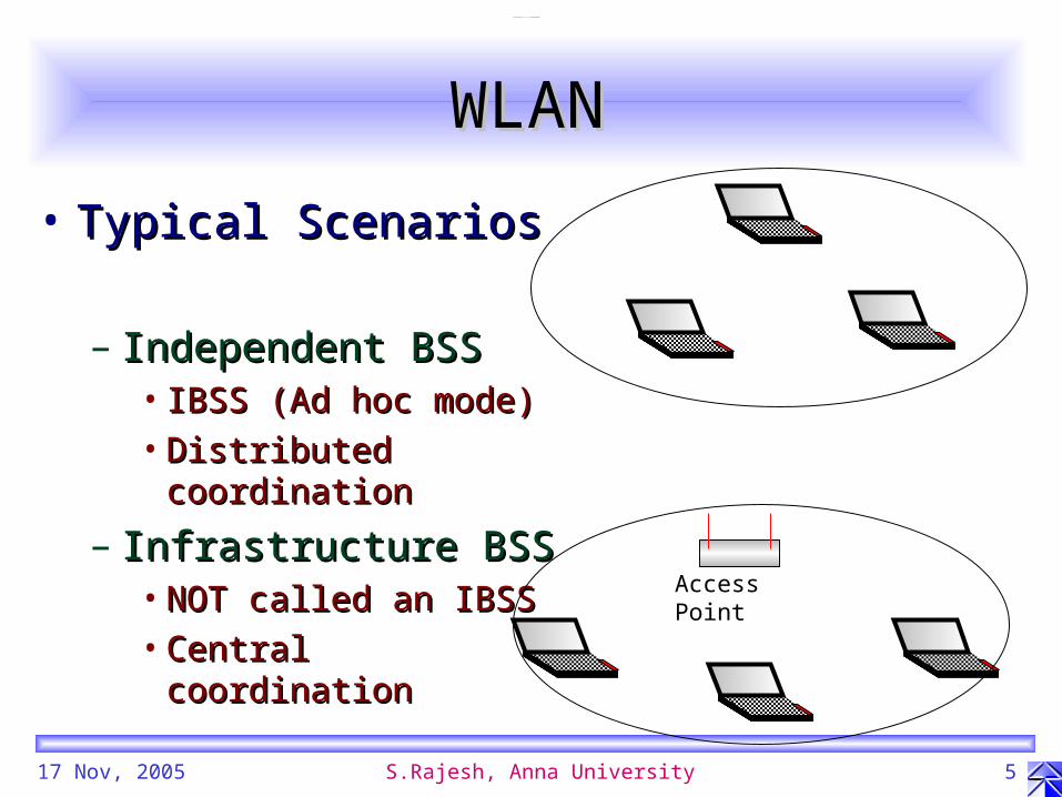
WLANWLAN
• Typical ScenariosTypical Scenarios
– Independent BSSIndependent BSS• IBSS (Ad hoc mode)IBSS (Ad hoc mode)• Distributed coordinationDistributed coordination
– Infrastructure BSSInfrastructure BSS• NOT called an IBSSNOT called an IBSS• Central coordinationCentral coordination
Access Point

17 Nov, 2005 S.Rajesh, Anna University 6
ESSESS
Access Point
Internet
LAN
WLAN
Backbone
Access Point
BSS BSS
ESS

17 Nov, 2005 S.Rajesh, Anna University 7
Basic IEEE 802.11 MACBasic IEEE 802.11 MAC
• CSMA/CA CSMA/CA
• Binary Exponential Back-offBinary Exponential Back-off
• RTS/CTS/Data/ACK handshakeRTS/CTS/Data/ACK handshake
• ModesModes– DCF DCF
• Ad Hoc or infrastructurelessAd Hoc or infrastructureless
– PCFPCF• Infrastructure based Infrastructure based
– Access Point polls the associated stationsAccess Point polls the associated stations

17 Nov, 2005 S.Rajesh, Anna University 8
DCFDCF
D S S S D N ST S S
1
2
3
D S S S D BkOff S S time
802.11a parametersS SIFS (Short Inter Frame Space) 16sD DIFS (DCF Inter Frame Space) 34sST Slot Time for each Back-off counter 9 s
RTS
CTS
DATA
ACK
RTS
CTS
DATA
NAV (RTS from 1)
NAV (RTS from 3)

17 Nov, 2005 S.Rajesh, Anna University 9
DCFDCF
• BeaconBeacon» generated by any of the nodes in the IBSSgenerated by any of the nodes in the IBSS
• MPDU transmissionMPDU transmission» If channel is free for a DIFS transmit (RTS,…, Data,...)If channel is free for a DIFS transmit (RTS,…, Data,...)» else else » wait till it becomes free for a DIFSwait till it becomes free for a DIFS
» generate random backoff slot-times in (0-Cwgenerate random backoff slot-times in (0-Cwminmin))
» if channel is free count down one slot timeif channel is free count down one slot time» else freeze and resume countdown else freeze and resume countdown » the channel becomes free for a DIFSthe channel becomes free for a DIFS» on reaching zero transmiton reaching zero transmit» if failed retry from first step (for max retries (7) times)if failed retry from first step (for max retries (7) times)

17 Nov, 2005 S.Rajesh, Anna University 10
PCFPCF
BeaconData & CF Poll to 1
CF Poll to 2 &
Ack to 1
Data from 1 &CF
Ack
CF Poll to 3
CF Ack
PC
NAV
M1
NAV
M2
Dead
NAV
M3
NAV
M4,5
IBSS
NAV Time -->
CF End
Contention Free Repetition Interval
Contention periodContention Free Period
Set by Beacon Cleared by CF End
Set by Beacon
Set by Beacon
Cleared by CF End
Cleared by CF End
RTS
CTS
DataAck
SIFS SIFS SIFS PIFS SIFS SIFS DIFS +BK SIFS SIFS SIFS
Set by RTS

17 Nov, 2005 S.Rajesh, Anna University 11
PCFPCF
• BeaconBeacon» always generated by the APalways generated by the AP
• TransmissionTransmission» AP transmits Multicast/Broadcast data firstAP transmits Multicast/Broadcast data first» AP transmits data to associated stations one by one and AP transmits data to associated stations one by one and
along with that it polls these stations to send data if any along with that it polls these stations to send data if any in contention free modein contention free mode
» If the station doesn’t respond within PIFS, the AP gets If the station doesn’t respond within PIFS, the AP gets the channel with better chance as PIFS<DIFSthe channel with better chance as PIFS<DIFS
» After CFPmaxduration channel is left for contention After CFPmaxduration channel is left for contention based accessbased access
» Contention Free Period and Contention Period alternateContention Free Period and Contention Period alternate

17 Nov, 2005 S.Rajesh, Anna University 12
HCFHCF
BeaconData & CF Poll to 1
CF Poll to 2 &
Ack to 1
Data from 1 &CF
Ack
CF Poll to 3
CF Ack
PC
NAV
M1
NAV
M2
Dead
NAV
M3
NAV
M4,5
IBSS
NAV Time -->
CF End
Contention Free Repetition Interval
Contention periodContention Free Period
Set by Beacon Cleared by CF End
Set by Beacon
Set by Beacon
Cleared by CF End
Cleared by CF End
RTS
CTS
DataAck
SIFS SIFS SIFS PIFS SIFS SIFS AIFS+BK SIFS SIFS SIFS
Set by RTS
Reserved by TXOP Reserved by TXOP
Reserved by TXOP
Reserved by TXOP
Reserved by TXOP
Reserved by TXOP
Reserved by TXOP

17 Nov, 2005 S.Rajesh, Anna University 13
EDCF QueuingEDCF Queuing
Mapping toAccess Category
Transmit Queues
Per-queuechannel accessfunctions withinternal collisionresolution

17 Nov, 2005 S.Rajesh, Anna University 14
AIFSAIFS
Medium Busy
D1
M1
Rx/Tx
D2
CCADel
M2
Rx/Tx
D2
CCADel
M2
Rx/Tx
D2
CCADel
M2
Rx/Tx
aSIFSTime aSlotTime aSlotTime aSlotTime
DIFS
AIFSD for AIFS=1
aSlotTime aSlotTime aSlotTime
Start monitoring CCAwhen AIFS=1
Decrement backoff andstart transmission if zero
when AIFS=1
Earliest possibletransmission on-air when
AIFS=1

Problem Definition and Problem Definition and ContributionContribution
IntroductionIntroduction
Problem Definition & ContributionProblem Definition & Contribution
MAC Enhancements (Ad hoc / WLAN)MAC Enhancements (Ad hoc / WLAN)
System Model (Ad hoc / WLAN)System Model (Ad hoc / WLAN)
Results (Ad hoc / WLAN)Results (Ad hoc / WLAN)
ConclusionConclusion

17 Nov, 2005 S.Rajesh, Anna University 16
Problem DefinitionProblem Definition
• Link level QoS support inLink level QoS support in– Ad hoc networksAd hoc networks– WLANsWLANs
• Differentiated Differentiated – Access Category basedAccess Category based
• IntegratedIntegrated– Guaranteed QoSGuaranteed QoS

17 Nov, 2005 S.Rajesh, Anna University 17
ContributionContribution
• MAC enhancements to support QoSMAC enhancements to support QoS– In ad hoc networksIn ad hoc networks
• Using directionality of the directional antennaUsing directionality of the directional antenna• Using intermittent immobile nodesUsing intermittent immobile nodes• Using direction aware schedulerUsing direction aware scheduler
– In WLANIn WLAN• Using estimation based Using estimation based
– Scheduler linked withScheduler linked with» Traffic shaping and policing Traffic shaping and policing » Admission ControlAdmission Control

MAC Enhancements in Ad hoc MAC Enhancements in Ad hoc NetworksNetworks
IntroductionIntroduction
Problem Definition and ContributionProblem Definition and Contribution
MAC Enhancements (Ad hoc Networks)MAC Enhancements (Ad hoc Networks)
System Model (Ad hoc / WLAN)System Model (Ad hoc / WLAN)
Results (Ad hoc / WLAN)Results (Ad hoc / WLAN)
ConclusionConclusion

17 Nov, 2005 S.Rajesh, Anna University 19
• Ad hoc networksAd hoc networks– Structural aspects:Structural aspects:
• topology free, infrastructure topology free, infrastructure independentindependent
– Functional aspects:Functional aspects:• multi-hop, common frequency multi-hop, common frequency
band for all nodes, no central band for all nodes, no central coordinationcoordination
– More overhead / expense on:More overhead / expense on:• routing, MAC, power routing, MAC, power
consumptionconsumption
– due todue to » highly dynamic state and highly dynamic state and
random state transitions, random state transitions, distributed coordinationdistributed coordination
Solution - StructuringSolution - Structuring

17 Nov, 2005 S.Rajesh, Anna University 20
Ad hoc Network - ChallengesAd hoc Network - Challenges
Disconnected Clusters
Stray Nodes
Bottle Necks

17 Nov, 2005 S.Rajesh, Anna University 21
EnhancementsEnhancements
• UseUse– interspersed stationary nodesinterspersed stationary nodes
• to reduce probability of any region getting void of to reduce probability of any region getting void of even a single node to connect witheven a single node to connect with
– directional antenna in these nodesdirectional antenna in these nodes• to improve range (without power-back-off)to improve range (without power-back-off)• to improve frequency reuse (with power-back-off)to improve frequency reuse (with power-back-off)
– smart directionality schedulersmart directionality scheduler• to help high priority node(s) or traffic to gain accessto help high priority node(s) or traffic to gain access• to prevent starvation of lower priority node(s) or trafficto prevent starvation of lower priority node(s) or traffic

17 Nov, 2005 S.Rajesh, Anna University 22
… … contd …contd …
Bottle NecksBottle Necks: Providing more buffers at the strategically placed directional nodes
Stray NodesStray Nodes: High priority far off nodes can be reached with long beam
Disconnected ClustersDisconnected Clusters: Various beam shapes of Directional nodes can form an underlying infrastructure

System Model Ad hoc NetworksSystem Model Ad hoc Networks
IntroductionIntroduction
Problem Definition and ContributionProblem Definition and Contribution
MAC Enhancements (Ad hoc / WLAN)MAC Enhancements (Ad hoc / WLAN)
System Model (Ad hoc Networks)System Model (Ad hoc Networks)
Results (Ad hoc / WLAN)Results (Ad hoc / WLAN)
ConclusionConclusion

17 Nov, 2005 S.Rajesh, Anna University 24
• Omni-directionalOmni-directional
• Directional AntennaDirectional Antenna– BeamBeam
• singlesingle• multimulti
– PowerPower• same as omni-directionalsame as omni-directional• backed-offbacked-off / / increasedincreased
Antenna PatternsAntenna Patterns

17 Nov, 2005 S.Rajesh, Anna University 25
MAC Based on AntennaMAC Based on Antenna
• Omni-directional Omni-directional (e.g.: RTS/CTS/Data/Ack, CSMA/CA as in DCF of IEEE 802.11)(e.g.: RTS/CTS/Data/Ack, CSMA/CA as in DCF of IEEE 802.11)
• DirectionalDirectional– Static directionalityStatic directionality
• based onbased on– node distribution where node density is morenode distribution where node density is more
– need for bridging or relayingneed for bridging or relaying
– Dynamic directionalityDynamic directionality• based onbased on
– (source, destination) pairs(source, destination) pairs
– Traffic Traffic
» Traffic intensity for uniform trafficTraffic intensity for uniform traffic
» Traffic categoryTraffic category

17 Nov, 2005 S.Rajesh, Anna University 26
State diagram of enhanced MACState diagram of enhanced MAC

17 Nov, 2005 S.Rajesh, Anna University 27
Results inResults in
• Improved connectivityImproved connectivity
• Improved QoSImproved QoS

17 Nov, 2005 S.Rajesh, Anna University 28
Connectivity Improvement with Connectivity Improvement with Stationary NodesStationary Nodes
• ProbabilityProbability– that two mobile nodes that two mobile nodes
contact at single hopcontact at single hop– that a mobile and a that a mobile and a
immobile node contact immobile node contact at single hopat single hop
• Improvement factor in Improvement factor in contact probabilitycontact probability
17 Nov, 2005 S.Rajesh, Anna University 29
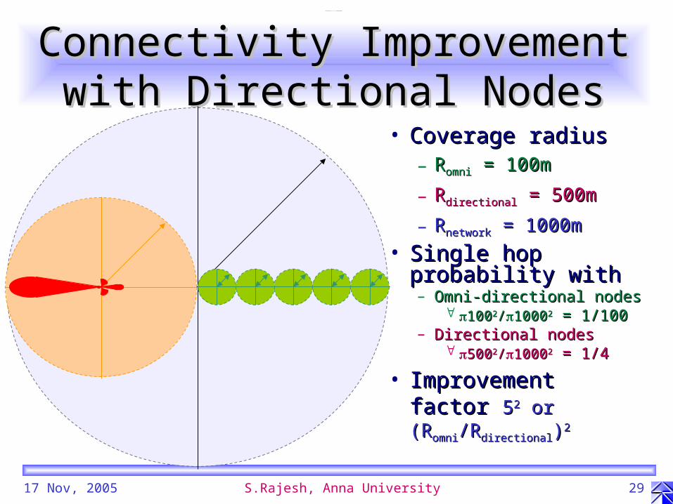
Connectivity Improvement with Connectivity Improvement with Directional NodesDirectional Nodes
• Coverage radiusCoverage radius– RRomniomni = 100m = 100m
– RRdirectionaldirectional = 500m = 500m
– RRnetworknetwork = 1000m = 1000m
• Single hop Single hop probability withprobability with– Omni-directional nodesOmni-directional nodes
10010022//1000100022 = 1/100 = 1/100– Directional nodesDirectional nodes
50050022//1000100022 = 1/4 = 1/4
• Improvement factorImprovement factor 5522 or (R or (Romniomni/R/Rdirectionaldirectional))22

17 Nov, 2005 S.Rajesh, Anna University 30
Traffic Intensity CalculationTraffic Intensity Calculation

17 Nov, 2005 S.Rajesh, Anna University 31
Traffic Based Direction Traffic Based Direction Scheduling for Better QoSScheduling for Better QoS
p is the priority weight of the corresponding traffic class

17 Nov, 2005 S.Rajesh, Anna University 32
ScenarioScenario
• All mobile caseAll mobile case
• With intermittent mobile nodesWith intermittent mobile nodes– without directional antennaswithout directional antennas– with directional antennaswith directional antennas
• with smart traffic-intensity based schedulingwith smart traffic-intensity based scheduling• with smart traffic-category based schedulingwith smart traffic-category based scheduling

17 Nov, 2005 S.Rajesh, Anna University 33
Simulation ParametersSimulation Parameters
• Network DiameterNetwork Diameter• Antenna PatternAntenna Pattern
– Omni-directional: radiusOmni-directional: radius– DirectionalDirectional
• beam width (lower limit)beam width (lower limit)• range (upper limit)range (upper limit)
• Access MethodAccess Method
• Routing TechniqueRouting Technique
2000m2000m
100m100m
22/6.25 for reaching/6.25 for reaching
250m with same power250m with same power
802.11 MAC802.11 MACCSMA/CACSMA/CA
RTS/CTS/Data/ACKRTS/CTS/Data/ACK
Shortest PathShortest Path

17 Nov, 2005 S.Rajesh, Anna University 34
……Contd...Contd...Simulation ParametersSimulation Parameters
Best E ffo rtA C = 0
E xp on en tia l
N on Q oSTra ffic
Video P robeA C = 1
P are to w ith cu to ff(1 .7 , 1 8 6 4 b its , 1 2 0 0 0 b its )
VideoA C = 2
P are to w ith cu to ff(1 .1 , 6 5 2 b its , 1 2 0 0 0 b its )
AudioA C = 3C B R
3 2 & 6 4 K b p s
Q oSTra ffic
T raffic T ypeA ccess C ateg ory
Non Preemptive scheduling FCFS
Scheduler
More Delay sensitiveLess Delay sensitive
Preemptive scheduling

ResultsResults
IntroductionIntroduction
Problem Definition and ContributionProblem Definition and Contribution
MAC Enhancements (Ad hoc / WLAN) MAC Enhancements (Ad hoc / WLAN)
System Model (Ad hoc / WLAN)System Model (Ad hoc / WLAN)
Results (Ad hoc Networks)Results (Ad hoc Networks)
ConclusionConclusion

17 Nov, 2005 S.Rajesh, Anna University 36
Throughput PerformanceThroughput Performance

17 Nov, 2005 S.Rajesh, Anna University 37
Delay PerformanceDelay Performance

MAC Enhancements in WLANsMAC Enhancements in WLANs
IntroductionIntroduction
Problem Definition and ContributionProblem Definition and Contribution
MAC Enhancements (WLANS)MAC Enhancements (WLANS)
System Model (Ad hoc / WLAN)System Model (Ad hoc / WLAN)
Results (Ad hoc / WLAN)Results (Ad hoc / WLAN)
ConclusionConclusion

17 Nov, 2005 S.Rajesh, Anna University 39
Solution StructuringSolution Structuring
• To design a common scheduler To design a common scheduler – that can handle boththat can handle both
• (a) Contention free traffic and(a) Contention free traffic and• (b) Contention based traffic(b) Contention based traffic
– oror• (1) Traffic with resource reservation and(1) Traffic with resource reservation and• (2) Traffic without resource reservation(2) Traffic without resource reservation
• Though not necessary, (1) is handled using (a) and (2) using (b).Though not necessary, (1) is handled using (a) and (2) using (b).• Exceptionally some bursts are allowed for (1) in (b) also called CFB or Exceptionally some bursts are allowed for (1) in (b) also called CFB or
Contention Free BurstsContention Free Bursts

17 Nov, 2005 S.Rajesh, Anna University 40
System - Block DiagramSystem - Block Diagram
InputQueue
Twin TokenBucket
RED Queue AccessCategories (4)AC=0,1,2,3
Traffic Streams(variablenumber)
HCF
EDCFFIFO per AC
TSScheduler
Chan
nel
Rate,size control
Drop RateControl
Admissioncontrol
EDCFParameters
Packet PathControl Information Path

17 Nov, 2005 S.Rajesh, Anna University 41
Traffic FlowTraffic Flow
• Traffic ClassificationTraffic Classification– Traffic corresponding to declared Traffic Traffic corresponding to declared Traffic
Streams (TSs) Streams (TSs) • Shaped and Policed using Twin Token BucketShaped and Policed using Twin Token Bucket• Sent as per TS scheduler in HCFSent as per TS scheduler in HCF
– Traffic not associated with Traffic Streams (TSs)Traffic not associated with Traffic Streams (TSs)• RED queue mechanism usedRED queue mechanism used• Sent as per EDCF budget declared by HC in HCFSent as per EDCF budget declared by HC in HCF

17 Nov, 2005 S.Rajesh, Anna University 42
Twin Token BucketTwin Token Bucketr2 tokens/s
Overflow
Droppedpackets
TokenAddition
Peak-ratelimited
s2
r1 tokens/s
Overflow
Droppedpackets
TokenAddition
Receivedtraffic
s1
Shapedtraffic
Bucket 1 Bucket 2Token filling rate (Constant) r1 = Peak Data Rate r2 = Mean Data RateBucket Size s1 = 1 token (mimic leaky bucket) s2 = Maximum Burst Size tokensToken extraction rate - At most Peak Data RateMajor purpose Rate limiting Burst size limiting
• TrafficTraffic– ShapingShaping– PolicingPolicing

17 Nov, 2005 S.Rajesh, Anna University 43
Scheduling Based on Packet Scheduling Based on Packet Error InformationError Information
• Scheduler schedules and admits Traffic Scheduler schedules and admits Traffic Streams based on effective bandwidthStreams based on effective bandwidth– Effective Mean Data Rate (EMDR)Effective Mean Data Rate (EMDR)
– control factor control factor n n is varied based on observed packet errorsis varied based on observed packet errors
EMDR (Mbps)
54--------
27---------
n
-infinity +infinity0
17 Nov, 2005 S.Rajesh, Anna University 44
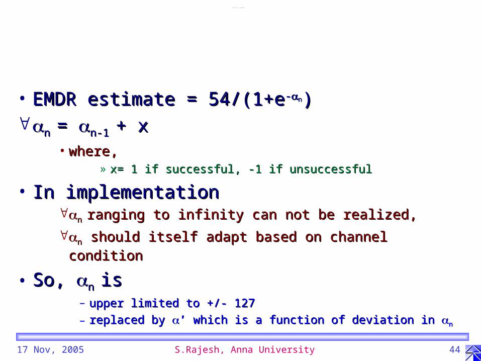
• EMDR estimate = 54/(1+eEMDR estimate = 54/(1+e--nn))n n = = n-1 n-1 + x+ x
• where, where, » x= 1 if successful, -1 if unsuccessful x= 1 if successful, -1 if unsuccessful
• In implementation In implementation n n ranging to infinity can not be realized, ranging to infinity can not be realized,
nn should itself adapt based on channel condition should itself adapt based on channel condition
• So, So, n n is is – upper limited to +/- 127upper limited to +/- 127
– replaced by replaced by ’ which is a function of deviation in ’ which is a function of deviation in n n

17 Nov, 2005 S.Rajesh, Anna University 45
• Aggregate the mean and peak data rate Aggregate the mean and peak data rate requirements mentioned through TSPEC for requirements mentioned through TSPEC for each admitted TSeach admitted TS
• Set rate of token filling in second bucket in Set rate of token filling in second bucket in Twin Token bucket , Twin Token bucket , rr22 to to
max(Estimated EMDR, algebraic sum of mean data rates of admitted TSs)max(Estimated EMDR, algebraic sum of mean data rates of admitted TSs)

17 Nov, 2005 S.Rajesh, Anna University 46
Admission PolicyAdmission Policy
• Admit Traffic Streams until aggregate mean Admit Traffic Streams until aggregate mean data rate of existing traffic streams does not data rate of existing traffic streams does not exceed EMDR, exceed EMDR, – (reject otherwise).(reject otherwise).
• Bandwidth not used for TS is allocated Bandwidth not used for TS is allocated through EDCF budget for Contention based through EDCF budget for Contention based accessaccess

17 Nov, 2005 S.Rajesh, Anna University 47
Scheduling Based on Rate Scheduling Based on Rate Adaptation InformationAdaptation Information
• Typically multiple rates are allowedTypically multiple rates are allowed– 54, 48, 36, 24, 18,12, 9, 6 Mbps54, 48, 36, 24, 18,12, 9, 6 Mbps
• Rate adaptation is done based RSSI or other Rate adaptation is done based RSSI or other techniquestechniques
• n n = = n-1 n-1 + x’+ x’
– where, x’ = x*(54*106)/rwhere, x’ = x*(54*106)/r• where, where,
» x= 1 if successful, -1 if unsuccessfulx= 1 if successful, -1 if unsuccessful
• andand» r is the rate of transmission of previous packet r is the rate of transmission of previous packet

17 Nov, 2005 S.Rajesh, Anna University 48
……Contd...Contd...Simulation ParametersSimulation Parameters
Best E ffo rtA C = 0
E xp on en tia l
N on Q oSTra ffic
Video P robeA C = 1
P are to w ith cu to ff(1 .7 , 1 8 6 4 b its , 1 2 0 0 0 b its )
VideoA C = 2
P are to w ith cu to ff(1 .1 , 6 5 2 b its , 1 2 0 0 0 b its )
AudioA C = 3C B R
3 2 & 6 4 K b p s
Q oSTra ffic
T raffic T ypeA ccess C ateg ory
Non Preemptive scheduling FCFS
Scheduler
More Delay sensitiveLess Delay sensitive
Preemptive scheduling

ResultsResults
IntroductionIntroduction
Problem Definition and ContributionProblem Definition and Contribution
MAC Enhancements (Ad hoc / WLAN) MAC Enhancements (Ad hoc / WLAN)
System Model (Ad hoc / WLAN)System Model (Ad hoc / WLAN)
Results (WLAN)Results (WLAN)
ConclusionConclusion

17 Nov, 2005 S.Rajesh, Anna University 50
Goodput of EDCFGoodput of EDCF

17 Nov, 2005 S.Rajesh, Anna University 51
Traffic Streams Supported for Different Peak Data Rate Traffic Streams Supported for Different Peak Data Rate Deviation on Ideal ChannelDeviation on Ideal Channel

17 Nov, 2005 S.Rajesh, Anna University 52
Traffic Streams supported and EDCF Throughput for a Traffic Streams supported and EDCF Throughput for a network when scheduler in HCF handles TXOPs of both network when scheduler in HCF handles TXOPs of both
contention free and contention based categoriescontention free and contention based categories

CONCLUSIONCONCLUSION
IntroductionIntroduction
Problem Definition and ContributionProblem Definition and Contribution
MAC Enhancements (Ad hoc / WLAN) MAC Enhancements (Ad hoc / WLAN)
System Model (Ad hoc / WLAN)System Model (Ad hoc / WLAN)
Results (Ad hoc / WLAN)Results (Ad hoc / WLAN)
ConclusionConclusion

17 Nov, 2005 S.Rajesh, Anna University 54
ConclusionConclusion
• In ad hoc networksIn ad hoc networks– Directional MAC - simple & robust technique to improveDirectional MAC - simple & robust technique to improve– Connectivity / CapacityConnectivity / Capacity– QoS performanceQoS performance
• In WLANs In WLANs – a scheduler with knowledge of a scheduler with knowledge of
• packet error information performs goodpacket error information performs good• rate adaptation mechanism provided by the management layer rate adaptation mechanism provided by the management layer
could help in better performance could help in better performance » particularly in poor channel conditionsparticularly in poor channel conditions

17 Nov, 2005 S.Rajesh, Anna University 55
Node Interactions with a Node Interactions with a Directional NodeDirectional Node
• Directional nodeDirectional node• Omni-directional nodesOmni-directional nodes
– reached by the reached by the directional nodedirectional node
– not reached by the not reached by the directional nodes butdirectional nodes but
• exposedexposed• not exposed andnot exposed and
– forming independent forming independent local network(s)local network(s)
– astrayastray

17 Nov, 2005 S.Rajesh, Anna University 56
Service Provider NetworkService Provider Network
• Building support Building support infrastructure infrastructure
• Combination ofCombination of– Stationary nodesStationary nodes
• omni-directional omni-directional (support in dense areas (support in dense areas with less or no mobility)with less or no mobility)
• directionaldirectional– static (relays on static (relays on
highways)highways)
– dynamic (in areas dynamic (in areas with highly random with highly random mobility)mobility)

17 Nov, 2005 S.Rajesh, Anna University 57
ReferencesReferences[1] M. Grossglauser and D. Tse, ``Mobility increases the capacity of ad-[1] M. Grossglauser and D. Tse, ``Mobility increases the capacity of ad-
hoc wireless networks,” hoc wireless networks,” Proc. INFOCOMProc. INFOCOM, pp. 1360-1369, April 2001., pp. 1360-1369, April 2001.
[2] M. Sanchez, T. Giles and J. Zander, ``CSMA/CA with Beam Forming [2] M. Sanchez, T. Giles and J. Zander, ``CSMA/CA with Beam Forming Antennas in Multi-hop Packet Radio,” Antennas in Multi-hop Packet Radio,” Proc. Swedish Workshop on Proc. Swedish Workshop on Wireless Ad hoc NetworksWireless Ad hoc Networks, March 2001., March 2001.
[3] O. Somarriba, ``Multihop Packet Radio Systems in Rough Terrain", [3] O. Somarriba, ``Multihop Packet Radio Systems in Rough Terrain", Licentiate Thesis, Radio Communication Systems, Department of S3, Licentiate Thesis, Radio Communication Systems, Department of S3, Royal Institute of Technology, SwedenRoyal Institute of Technology, Sweden, Oct. 1995., Oct. 1995.
[4] L. E. Miler, ``Multihop Connectivity of Arbitrary Networks", [4] L. E. Miler, ``Multihop Connectivity of Arbitrary Networks", Multihop Multihop ConnectivityConnectivity, NIST, March 2001., NIST, March 2001.
[5] ``IEEE 802.11b, Part 11: Wireless LAN MAC and PHY Specification: [5] ``IEEE 802.11b, Part 11: Wireless LAN MAC and PHY Specification: High-Speed Physical Layer Extension in the 2.4GHz Band", 1999.High-Speed Physical Layer Extension in the 2.4GHz Band", 1999.
[6] ``IEEE 802.11e, Part 11: Wireless LAN MAC and PHY Specification: [6] ``IEEE 802.11e, Part 11: Wireless LAN MAC and PHY Specification: MAC Enhancements for QoS”, D3.3, Oct 2002.MAC Enhancements for QoS”, D3.3, Oct 2002.

17 Nov, 2005 S.Rajesh, Anna University 58
ReferencesReferences
[1] "IEEE 802.11, Part 11: Wireless LAN Medium Access Control (MAC) and Physical Layer (PHY) Specification on 2.4GHz band," 1999.
[2] "IEEE 802.11a, Part 11: Wireless LAN Medium Access Control (MAC) and Physical Layer (PHY) Specificatio, on 5GHz band," 1999.
[3] Draft Supplement 4.1 "IEEE 802.11e, Part 11: Wireless LAN Medium Access Control (MAC) and Physical Layer (PHY) Specification: Medium Access Control (MAC) enhancements for Quality of Service (QoS)", Feb 2003.
[4] Andrew Moore, Simon Crosby, "Experimental results from a practical implementation of a Measurement Based CAC algorithm," BTL Final Report, May 1998.
[5] Sunghyun Choi, Javier del Prado, Sai Shankar N, and Stefan Mangold, "IEEE 802.11e Contention-Based Channel Access (EDCF) Performance Evaluation" in Proc. IEEE ICC 2003, Anchorage, Alaska, USA, May 2003.
[6] “An architecture for Differentiated services”, IETF RFC 2475, 1998.
[7] J. Wroclawski, "The use of RSVP with IETF integrated services," RFC 2210, Sept. 1997.
[8] IEEE Std 802.1Q-1998, IEEE Standards for Local and Metropolitan Area Networks: Virtual Bridged Local Area Networks.
[9] IETF RFC 2215, 2215 General Characterization Parameters for Integrated Service Network Elements. S.Shenker, J.Wroclawski. September 1997.
[10] S. Floyd and V. Jacobson, “Random early detection gateways for congestion avoidance”, IEEE/ACM Transactions on Networking, 1(4):397-413, August 1993.
[11] Javier del Prado and Sunghyun Choi, "Link Adaptation Strategy for IEEE 802.11 WLAN via Received Signal Strength Measurement," in Proc. IEEE ICC 2003, Anchorage, Alaska, USA, May 2003.

Thank YouThank You
S.Rajesh, S.Rajesh,
AU-KBC Research Centre,AU-KBC Research Centre,Department of Electronics Engineering, Faculty of Information and Communication Department of Electronics Engineering, Faculty of Information and Communication
Engineering, MIT Campus, Anna University, Chromepet, Chennai, TN 600044 INDIA.Engineering, MIT Campus, Anna University, Chromepet, Chennai, TN 600044 INDIA.
http://www.au-kbc.orghttp://www.au-kbc.org
http://www.annauniv.eduhttp://www.annauniv.edu

17 Nov, 2005 S.Rajesh, Anna University 60