MA2015-4 - 国土交通省 · PDF filecrane (hereinafter referred to as “Company...
13
MA2015-4 MARINE ACCIDENT INVESTIGATION REPORT March 26, 2015
Transcript of MA2015-4 - 国土交通省 · PDF filecrane (hereinafter referred to as “Company...
MA2015-4
MARINE ACCIDENT
INVESTIGATION REPORT
March 26, 2015

The objective of the investigation conducted by the Japan Transport Safety Board in
accordance with the Act for Establishment of the Japan Transport Safety Board is to determine the
causes of an accident and damage incidental to such an accident, thereby preventing future accidents
and reducing damage. It is not the purpose of the investigation to apportion blame or liability.
Norihiro Goto
Chairman,
Japan Transport Safety Board
Note:
This report is a translation of the Japanese original investigation report. The text in
Japanese shall prevail in the interpretation of the report.
- 1 -
MARINE ACCIDENT INVESTIGATION REPORT
March 12, 2015
Adopted by the Japan Transport Safety Board
Chairman Norihiro Goto
Member Kuniaki Shoji
Member Satoshi Kosuda
Member Toshiyuki Ishikawa
Member Mina Nemoto
Accident type Injury of worker
Date and time September 11, 2013, at about 17:00 (local time, UTC +9 hours)
Location Nakashima Quay No. 3, Port of Himeji, Himeji City, Hyogo Prefecture
160° true, 540 m from Shikama Higashi East No.2 Breakwater Lighthouse,
located in Himeji City
(approximately 34°46.2’ N, 134°39.6’E)
Summary of the Accident
The cargo ship GREEN HOPE, carrying the master and 20 crew members, was
discharging a cargo of timber at Nakashima Quay No. 3, Port of Himeji. At
about 17:00 on September 11, 2013, deck crane No. 1 collapsed and caused
injury to the crane operator.
Process and Progress of the
Investigation
(1) Setup of the investigation
The Japan Transport Safety Board appointed an investigator-in-charge and
one other investigator to investigate the accident on September 12, 2013.
(2) Collection of evidence
On-site investigation and interview on September 13 and 14, 2013,
interview on September 19 and 20, and November 5, 6 and 20, 2013,
interview on April 22, May 26, and July 25, 2014, collection of
questionnaire on October 2 and 8, 2013, January 20, April 25, May 9 and
27, June 4, July 2 and 28, August 6, 7 and 22, 2014, and interview and
collection of questionnaire on May 30, 2014.
(3) The National Maritime Research Institute has been tasked with the analysis
and investigation of a bolt fracture in connection with this accident.
(4) Comments on the draft report were invited from parties relevant to the cause
of the accident.
(5) Comments on the draft report were invited from the GREEN HOPE’s flag
state.
Factual Information
Vessel information
Vessel type and name
Cargo ship GREEN HOPE (hereinafter referred to as “the Ship”)

- 2 -
IMO number
Gross tonnage
Port of registry
Owner
Management company
Class
L×B×D, hull material
Engine, output, date of
launch
9261750
21,185 gt
Panama, Republic of Panama
TUI MARITIME S.A. (Republic of Panama)
Sojitz Marine & Engineering Corporation
NK
178.03 m × 28.00 m × 15.00 m, steel
Diesel engine, 7,080 kW, May 2002
Deck crane information
(1) The Ship was equipped with four deck cranes. Deck crane No. 1 (hereinafter
referred to “the crane”) was installed between cargo hold No. 1 nearest to
the bow and cargo hold No. 2 behind that. Deck cranes No. 2 to 4 were
installed similarly between the respective cargo holds No. 2 to 5. (Refer to
photograph 1.)
Photograph 1: External view of the deck cranes on the Ship
(2) The following is a description of the use of the deck cranes on the Ship.
① The Ship was loaded with approximately 36,000 pieces of timber from
a port in New Zealand, which was then unloaded at a Japanese port. She
made this journey on the average of eight to nine times a year.
② The maximum load that could be taken by the hooks on the deck crane
during the cargo handling was about 26 t in New Zealand, where wire
hooks were used, and about 22 t in Japan, where grab buckets were used.
③ The cargo handling was generally carried out on the starboard side.
(3) The performance, structure, and other aspects of the crane were as follows.
① Performance
The crane had a maximum slewing radius of 22 m, and a limit load of
30.5 t. Operation stopped when the limit load was exceeded.
② Structure
The crane was made up of a crane house, jib, wire rope, hook, and other
parts. It was attached to the top of the cylindrical post on the deck.
A hoisting and luffing winch, and other parts were set up inside the
crane house, while a slewing bearing was attached to the bottom part of
the crane house.
The crane
- 3 -
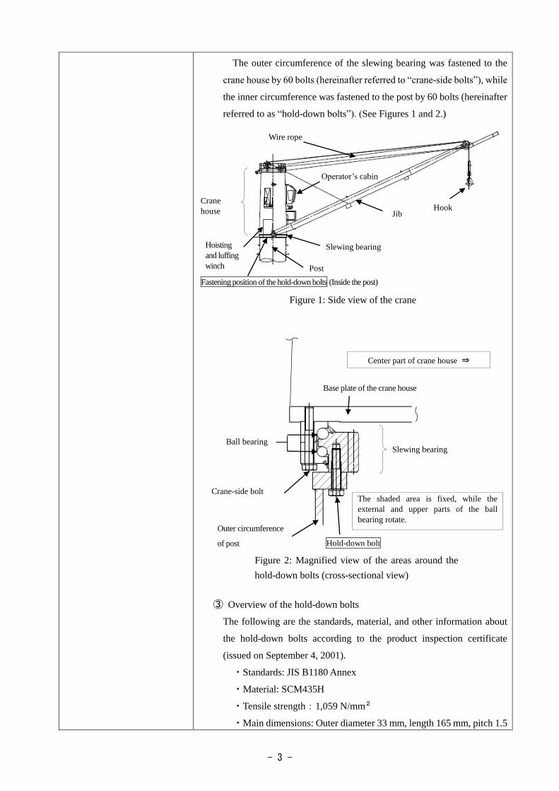
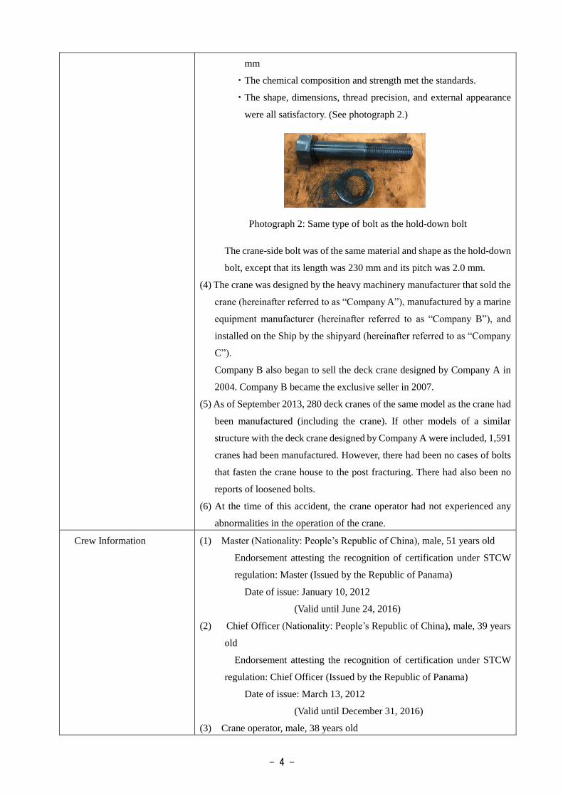
The outer circumference of the slewing bearing was fastened to the
crane house by 60 bolts (hereinafter referred to “crane-side bolts”), while
the inner circumference was fastened to the post by 60 bolts (hereinafter
referred to as “hold-down bolts”). (See Figures 1 and 2.)
Figure 1: Side view of the crane
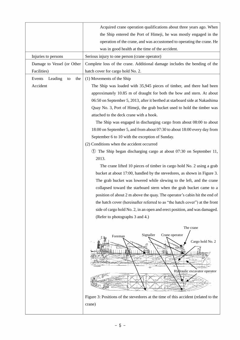
③ Overview of the hold-down bolts
The following are the standards, material, and other information about
the hold-down bolts according to the product inspection certificate
(issued on September 4, 2001).
・Standards: JIS B1180 Annex
・Material: SCM435H
・Tensile strength:1,059 N/mm2
・Main dimensions: Outer diameter 33 mm, length 165 mm, pitch 1.5
Hoisting
and luffing
winch
Crane
house
Operator’s cabin
Post
Jib
Slewing bearing
Hook
Base plate of the crane house
Hold-down bolt
Center part of crane house ⇒
Slewing bearing
Crane-side bolt The shaded area is fixed, while the
external and upper parts of the ball
bearing rotate.
Fastening position of the hold-down bolts (Inside the post)
Ball bearing
Figure 2: Magnified view of the areas around the
hold-down bolts (cross-sectional view)
Wire rope
Outer circumference
of post
- 4 -
mm
・The chemical composition and strength met the standards.
・The shape, dimensions, thread precision, and external appearance
were all satisfactory. (See photograph 2.)
The crane-side bolt was of the same material and shape as the hold-down
bolt, except that its length was 230 mm and its pitch was 2.0 mm.
(4) The crane was designed by the heavy machinery manufacturer that sold the
crane (hereinafter referred to as “Company A”), manufactured by a marine
equipment manufacturer (hereinafter referred to as “Company B”), and
installed on the Ship by the shipyard (hereinafter referred to as “Company
C”).
Company B also began to sell the deck crane designed by Company A in
2004. Company B became the exclusive seller in 2007.
(5) As of September 2013, 280 deck cranes of the same model as the crane had
been manufactured (including the crane). If other models of a similar
structure with the deck crane designed by Company A were included, 1,591
cranes had been manufactured. However, there had been no cases of bolts
that fasten the crane house to the post fracturing. There had also been no
reports of loosened bolts.
(6) At the time of this accident, the crane operator had not experienced any
abnormalities in the operation of the crane.
Crew Information (1) Master (Nationality: People’s Republic of China), male, 51 years old
Endorsement attesting the recognition of certification under STCW
regulation: Master (Issued by the Republic of Panama)
Date of issue: January 10, 2012
(Valid until June 24, 2016)
(2) Chief Officer (Nationality: People’s Republic of China), male, 39 years
old
Endorsement attesting the recognition of certification under STCW
regulation: Chief Officer (Issued by the Republic of Panama)
Date of issue: March 13, 2012
(Valid until December 31, 2016)
(3) Crane operator, male, 38 years old
Photograph 2: Same type of bolt as the hold-down bolt
- 5 -
Acquired crane operation qualifications about three years ago. When
the Ship entered the Port of Himeji, he was mostly engaged in the
operation of the crane, and was accustomed to operating the crane. He
was in good health at the time of the accident.
Injuries to persons Serious injury to one person (crane operator)
Damage to Vessel (or Other
Facilities)
Complete loss of the crane. Additional damage includes the bending of the
hatch cover for cargo hold No. 2.
Events Leading to the
Accident
(1) Movements of the Ship
The Ship was loaded with 35,945 pieces of timber, and there had been
approximately 10.85 m of draught for both the bow and stern. At about
06:50 on September 5, 2013, after it berthed at starboard side at Nakashima
Quay No. 3, Port of Himeji, the grab bucket used to hold the timber was
attached to the deck crane with a hook.
The Ship was engaged in discharging cargo from about 08:00 to about
18:00 on September 5, and from about 07:30 to about 18:00 every day from
September 6 to 10 with the exception of Sunday.
(2) Conditions when the accident occurred
① The Ship began discharging cargo at about 07:30 on September 11,
2013.
The crane lifted 10 pieces of timber in cargo hold No. 2 using a grab
bucket at about 17:00, handled by the stevedores, as shown in Figure 3.
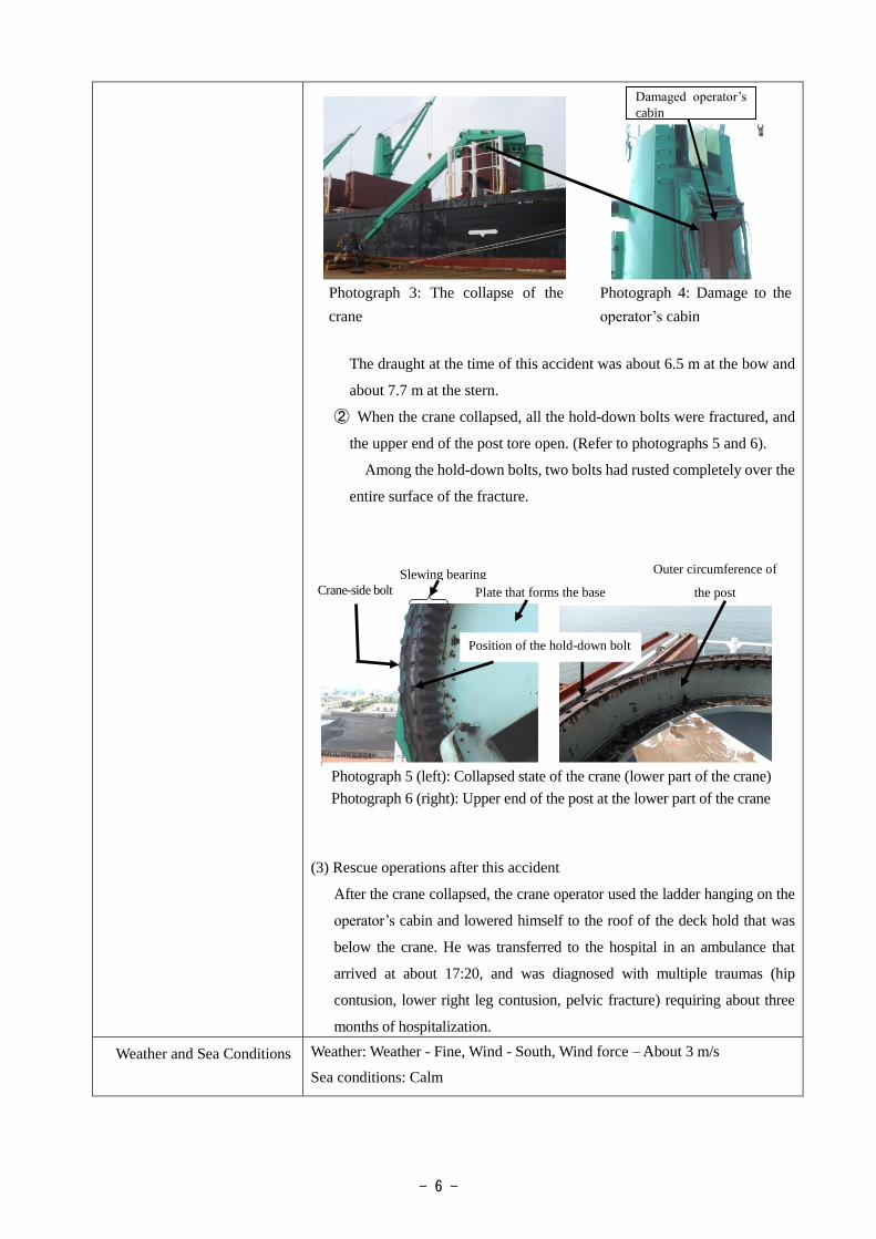
The grab bucket was lowered while slewing to the left, and the crane
collapsed toward the starboard stern when the grab bucket came to a
position of about 2 m above the quay. The operator’s cabin hit the end of
the hatch cover (hereinafter referred to as “the hatch cover”) at the front
side of cargo hold No. 2, in an open and erect position, and was damaged.
(Refer to photographs 3 and 4.)
Figure 3: Positions of the stevedores at the time of this accident (related to the
crane)
Foreman Signaller Crane operator
The crane
Cargo hold No. 2
Hydraulic excavator operator
- 6 -
Crane-side bolt
The draught at the time of this accident was about 6.5 m at the bow and
about 7.7 m at the stern.
② When the crane collapsed, all the hold-down bolts were fractured, and
the upper end of the post tore open. (Refer to photographs 5 and 6).
Among the hold-down bolts, two bolts had rusted completely over the
entire surface of the fracture.
(3) Rescue operations after this accident
After the crane collapsed, the crane operator used the ladder hanging on the
operator’s cabin and lowered himself to the roof of the deck hold that was
below the crane. He was transferred to the hospital in an ambulance that
arrived at about 17:20, and was diagnosed with multiple traumas (hip
contusion, lower right leg contusion, pelvic fracture) requiring about three
months of hospitalization.
Weather and Sea Conditions
Weather: Weather - Fine, Wind - South, Wind force – About 3 m/s
Sea conditions: Calm
Slewing bearing Outer circumference of
the post Plate that forms the base
Position of the hold-down bolt
Damaged operator’s
cabin
Photograph 3: The collapse of the
crane
Photograph 4: Damage to the
operator’s cabin
Photograph 5 (left): Collapsed state of the crane (lower part of the crane)
Photograph 6 (right): Upper end of the post at the lower part of the crane
- 7 -
Analysis of the fracture to
the hold-down bolts
conducted by the National
Maritime Research Institute
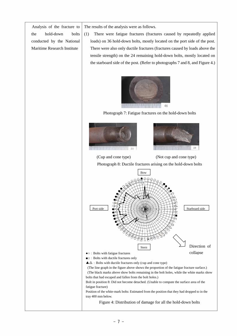
The results of the analysis were as follows.
(1) There were fatigue fractures (fractures caused by repeatedly applied
loads) on 36 hold-down bolts, mostly located on the port side of the post.
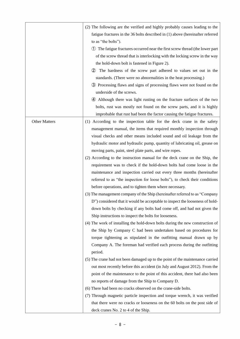
There were also only ductile fractures (fractures caused by loads above the
tensile strength) on the 24 remaining hold-down bolts, mostly located on
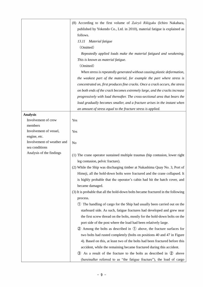
the starboard side of the post. (Refer to photographs 7 and 8, and Figure 4.)
Photograph 7: Fatigue fractures on the hold-down bolts
(Cup and cone type) (Not cup and cone type)
Photograph 8: Ductile fractures arising on the hold-down bolts
●○:Bolts with fatigue fractures
■□:Bolts with ductile fractures only
▲△:Bolts with ductile fractures only (cup and cone type)
(The line graph in the figure above shows the proportion of the fatigue fracture surface.)
(The black marks above show bolts remaining in the bolt holes, while the white marks show
bolts that had escaped and fallen from the bolt holes.)
Bolt in position 8: Did not become detached. (Unable to compute the surface area of the
fatigue fracture)
Position of the white-mark bolts: Estimated from the position that they had dropped to in the
tray 400 mm below.
Figure 4: Distribution of damage for all the hold-down bolts
Starboard side
Direction of
collapse
Port side
Bow
Stern
- 8 -
(2) The following are the verified and highly probably causes leading to the
fatigue fractures in the 36 bolts described in (1) above (hereinafter referred
to as “the bolts”).
① The fatigue fractures occurred near the first screw thread (the lower part
of the screw thread that is interlocking with the locking screw in the way
the hold-down bolt is fastened in Figure 2).
② The hardness of the screw part adhered to values set out in the
standards. (There were no abnormalities in the heat processing.)
③ Processing flaws and signs of processing flaws were not found on the
underside of the screws.
④ Although there was light rusting on the fracture surfaces of the two
bolts, rust was mostly not found on the screw parts, and it is highly
improbable that rust had been the factor causing the fatigue fractures.
Other Matters
(1) According to the inspection table for the deck crane in the safety
management manual, the items that required monthly inspection through
visual checks and other means included sound and oil leakage from the
hydraulic motor and hydraulic pump, quantity of lubricating oil, grease on
moving parts, paint, steel plate parts, and wire ropes.
(2) According to the instruction manual for the deck crane on the Ship, the
requirement was to check if the hold-down bolts had come loose in the
maintenance and inspection carried out every three months (hereinafter
referred to as “the inspection for loose bolts”), to check their conditions
before operations, and to tighten them where necessary.
(3) The management company of the Ship (hereinafter referred to as “Company
D”) considered that it would be acceptable to inspect the looseness of hold-
down bolts by checking if any bolts had come off, and had not given the
Ship instructions to inspect the bolts for looseness.
(4) The work of installing the hold-down bolts during the new construction of
the Ship by Company C had been undertaken based on procedures for
torque tightening as stipulated in the outfitting manual drawn up by
Company A. The foreman had verified each process during the outfitting
period.
(5) The crane had not been damaged up to the point of the maintenance carried
out most recently before this accident (in July and August 2012). From the
point of the maintenance to the point of this accident, there had also been
no reports of damage from the Ship to Company D.
(6) There had been no cracks observed on the crane-side bolts.
(7) Through magnetic particle inspection and torque wrench, it was verified
that there were no cracks or looseness on the 60 bolts on the post side of
deck cranes No. 2 to 4 of the Ship.
- 9 -
(8) According to the first volume of Zairyō Rikigaku (Ichiro Nakahara,
published by Yokendo Co., Ltd. in 2010), material fatigue is explained as
follows.
13.11 Material fatigue
(Omitted)
Repeatedly applied loads make the material fatigued and weakening.
This is known as material fatigue.
(Omitted)
When stress is repeatedly generated without causing plastic deformation,
the weakest part of the material, for example the part where stress is
concentrated on, first produces fine cracks. Once a crack occurs, the stress
on both ends of the crack becomes extremely large, and the cracks increase
progressively with load thereafter. The cross-sectional area that bears the
load gradually becomes smaller, and a fracture arises in the instant when
an amount of stress equal to the fracture stress is applied.
Analysis
Involvement of crew
members
Involvement of vessel,
engine, etc.
Involvement of weather and
sea conditions
Analysis of the findings
Yes
Yes
No
(1) The crane operator sustained multiple traumas (hip contusion, lower right
leg contusion, pelvic fracture).
(2) While the Ship was discharging timber at Nakashima Quay No. 3, Port of
Himeji, all the hold-down bolts were fractured and the crane collapsed. It
is highly probable that the operator’s cabin had hit the hatch cover, and
became damaged.
(3) It is probable that all the hold-down bolts became fractured in the following
process.
① The handling of cargo for the Ship had usually been carried out on the
starboard side. As such, fatigue fractures had developed and grew near
the first screw thread on the bolts, mostly for the hold-down bolts on the
port side of the post where the load had been relatively large.
② Among the bolts as described in ① above, the fracture surfaces for
two bolts had rusted completely (bolts on positions 40 and 47 in Figure
4). Based on this, at least two of the bolts had been fractured before this
accident, while the remaining became fractured during this accident.
③ As a result of the fracture to the bolts as described in ② above
(hereinafter referred to as “the fatigue fracture”), the load of cargo

- 10 -
handling was placed on the 24 bolts, mostly the hold-down bolts on the
starboard side of the post that had not suffered from any fatigue fractures.
Hence, these bolts became fractured.
(4) Based on the following reasoning, it is somewhat likely that the fatigue
fracture on the bolts had resulted from repeated cargo handling with some
of the bolts in a loosened condition (including the two bolts in (3)②
above).
Typically, fatigue fractures arise in a bolt in one of the following cases:
① when excessive external force is applied repeatedly to the bolt, or ②
when external force is applied repeatedly to the bolt in a state of stress
concentration arising from fine cracks.
Hence, the cause leading to the fatigue fracture on the screw part of the
bolts, as shown in the following table, are hypothesized to be a ~ c.
However, cases a and c did not arise during the actual handling of cargo on
the Ship, and it is probable that b had occurred.
On the other hand, the situation leading to the loosening of some of the
bolts could not be elucidated, and it could not be verified that the bolts had
become loosened.
(5) As Company D had not given the Ship instructions to inspect the bolts for
looseness as stipulated in the instruction manual, it is somewhat likely that
repeated cargo handling was carried out with some of the bolts in a loosened
state.
Probable Causes It is probable that this accident, which occurred on the Ship at Nakashima
Quay No. 3, Port of Himeji, had occurred due to fatigue fractures in the bolts
during the discharging of timber from the Ship, which caused all the remaining
hold-down bolts that took on the full weight of the load to become fractured,
the crane to collapse, and the operator’s cabin to hit the hatch cover.
① Excessive external force applied repeatedly to the
bolts
②External force applied repeatedly
to the bolt in a state of stress
concentration arising from fine
cracks
Hypothesis a. Repeated cargo handling
exceeding the limit load.
b. Repeated cargo handling
with some of the bolts in
a loosened state.
c. Repeated cargo handling with fine
cracks in the screw parts that had
arisen from impact or other
factors.
Actua l
ca rgo
handl ing
The actual weight of the
load during the cargo
handling had been less than
the limit load. Even if the
limit load had been
exceeded, the crane would
have stopped operating.
As inspection had not been
carried out for the
loosening of the bolts, the
bolts had not been
tightened. There was room
for the probability of case b
occurring.
The crane and the crane-side bolts
did not incur any damage through
impact or other factors. As such,
cracks did not develop in the bolts
as a result of impact or other factors.

- 11 -
It is somewhat likely that the fatigue fracture to the bolts had resulted from
repeated cargo handling with some of the bolts in a loosened state.
It is somewhat likely that the repeated cargo handling with some of the bolts
in a loosened state had occurred because Company D had not given the Ship
instructions to inspect the bolts for looseness as stipulated in the instruction
manual.
Safety Actions
After this accident, Company A issued a document dated October 23, 2013,
requesting ship management companies and owners of ships equipped with
deck cranes designed and sold by the company to promptly check all bolts
following the breakage of hold-down bolts, to take measures such as tightening
of bolts when loosened bolts are found, and to disseminate the information to
all parties concerned in case that ownership changes.
Since December 2013, Company B has explained to crew members the need
to carry out inspections for loosened bolts when delivering ships equipped with
the deck cranes that it sells. In addition, from November to December 2014
Company B also made the same request regarding the contents in the document
described above to the ship management companies and owners of ships
equipped with deck cranes designed by Company A except those Company A
had already informed.
Starting January 20, 2014, Company C has recorded torque-tightening work
during the installation of hold-down bolts, and carried out this work using
checklists that are checked by several people.
The following measures would help to prevent recurrence of similar
accidents:
・With regard to inspections for loosened bolts in order to prevent the
collapse of deck cranes, give instruction from Company D to the master
and crewmembers in charge of inspections, developing a reliable
implementation method through the use of an inspection table or other
means, based on accurate technical information from the manufacturer
and instruction manuals.