
ma ts8 innenseiten - Amazon Simple Storage Service · – Removing the roof plate 11 – Moving the...
28
TS 8 Montage- und Bedienungsanleitung Assembly and operating instructions Notice d’emploi et de montage Montage- en bedieningshandleiding Montage- och bruksanvisning Istruzioni di montaggio Instrucciones de montaje TS 8004.500 TS 8005.500 TS 8006.500 TS 8080.500 TS 8084.500 TS 8204.500 TS 8205.500 TS 8206.500 TS 8208.500 TS 8215.500 TS 8226.500 TS 8245.500 TS 8265.500 TS 8284.500 TS 8285.500 TS 8286.500 TS 8405.510 TS 8406.510 TS 8450.600 TS 8451.600 TS 8452.600 TS 8453.600 TS 8454.600 TS 8455.600 TS 8456.600 TS 8457.600 TS 8485.510 TS 8486.510 TS 8604.500 TS 8605.500 TS 8606.500 TS 8608.500 TS 8615.500 TS 8626.500 TS 8645.500 TS 8665.500 TS 8684.500 TS 8685.500 TS 8686.500 TS 8804.500 TS 8805.500 TS 8806.500 TS 8808.500 TS 8815.500 TS 8826.500 TS 8845.500 TS 8865.500 TS 8880.500 TS 8881.500 TS 8884.500 TS 8885.500 TS 8886.500
Transcript of ma ts8 innenseiten - Amazon Simple Storage Service · – Removing the roof plate 11 – Moving the...

TS 8
Montage- und BedienungsanleitungAssembly and operating instructionsNotice d’emploi et de montageMontage- en bedieningshandleidingMontage- och bruksanvisningIstruzioni di montaggioInstrucciones de montaje
TS 8004.500
TS 8005.500
TS 8006.500
TS 8080.500
TS 8084.500
TS 8204.500
TS 8205.500
TS 8206.500
TS 8208.500
TS 8215.500
TS 8226.500
TS 8245.500
TS 8265.500
TS 8284.500
TS 8285.500
TS 8286.500
TS 8405.510
TS 8406.510
TS 8450.600
TS 8451.600
TS 8452.600
TS 8453.600
TS 8454.600
TS 8455.600
TS 8456.600
TS 8457.600
TS 8485.510
TS 8486.510
TS 8604.500
TS 8605.500
TS 8606.500
TS 8608.500
TS 8615.500
TS 8626.500
TS 8645.500
TS 8665.500
TS 8684.500
TS 8685.500
TS 8686.500
TS 8804.500
TS 8805.500
TS 8806.500
TS 8808.500
TS 8815.500
TS 8826.500
TS 8845.500
TS 8865.500
TS 8880.500
TS 8881.500
TS 8884.500
TS 8885.500
TS 8886.500

2 Rittal Anreih-System TS 8 Montageanleitung
3 – 7/25 – 27 8/9 10 10 11 12/13
F
14 22 23 23 24 24
EN FD
D
Lieferumfang und technische Informationen 3/4
Hinweise zur Dokumentation
– CE-Kennzeichnung 5
– Aufbewahrung der Unterlagen 5
– Verwendete Symbole 6
Sicherheitshinweise 6
Montage und Aufstellung
– Anforderungen an den Aufstellort 7
– Hinweise zur Montage 7
– Hinweise zur Bedienung 7
Montage
– Tür demontieren 8
– Türanschlagwechsel 8/9
– Türrohrrahmen demontieren 10
– Rückwand demontieren 10
– Dachblech demontieren 11
– Montageplatte versetzen 12/13
– Bodenbleche montieren 14
– Wechsel des Verschluss-Einsatzes 15
– 180°-Scharniere montieren 16
– Innenausbau Schienensysteme 17
– Seitenwände montieren 18
– Montageplatten-Zwischenstück montieren 19
– Anreihung 20/21
Erdung und Potenzialausgleich 22
Transport 23
Aufstellung 24
Technische Daten 25
Hinweise zur Wartung 26
Garantie 27
Kundendienstadressen 27
EN
Scope of delivery and technical information 3/4
Notes on documentation
– CE labelling 5
– Retention of documents 5
– Symbols used 6
Safety notes 6
Assembly and siting
– Installation requirements 7
– Notes on assembly 7
– Notes on operation 7
Assembly
– Removing the door 8
– Switching the door hinges 8/9
– Removing the tubular door frame 10
– Removing the rear panel 10
– Removing the roof plate 11
– Moving the mounting plate 12/13
– Fitting gland plates 14
– Changing the lock insert 15
– Fitting 180° hinges 16
– Installing mounting angle systems 17
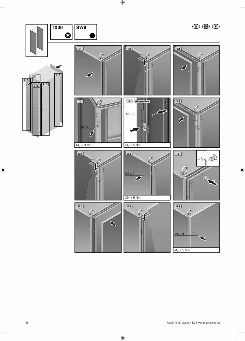
– Fitting the side panels 18
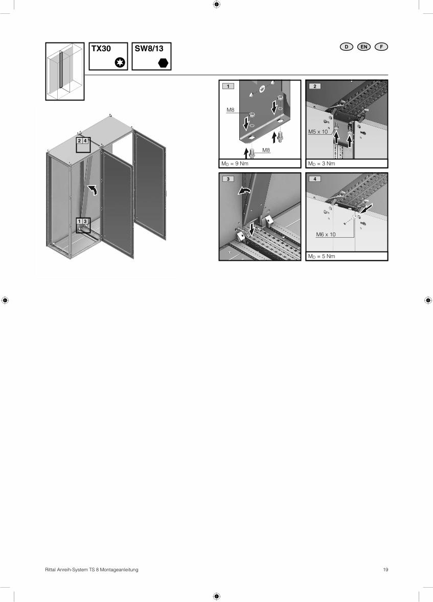
– Fitting the mounting plate infi ll 19
– Baying 20/21
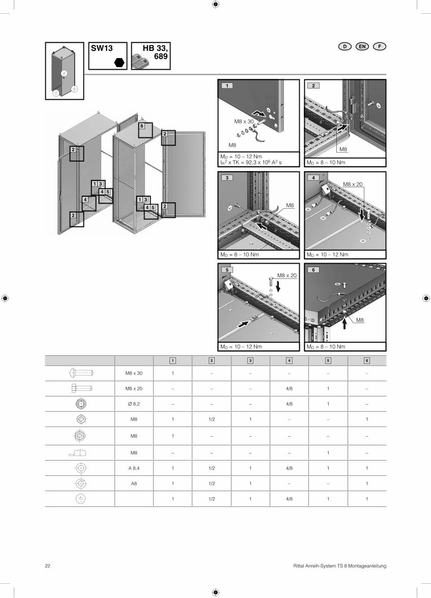
Earthing and potential equalisation 22
Transport 23
Siting 24
Technical data 25
Notes on maintenance 26
Warranty 27
Customer service addresses 27
F
Limites de fourniture et informations techniques 3/4
Remarques relatives à la documentation
– Certifi cation CE 5
– Conservation des documents 5
– Symboles utilisés 6
Consignes de sécurité 6
Montage et implantation
– Exigences vis à vis du lieu d’implantation 7
– Consignes de montage 7
– Consignes d’utilisation 7
Montage
– Démontage de la porte 8
– Inversion du sens d’ouverture 8/9
– Démontage du cadre de porte tubulaire 10
– Démontage du panneau arrière 10
– Démontage du toit 11
– Déplacement de la plaque de montage 12/13
– Montage des plaques passe-câbles 14
– Remplacement du dispositif de verrouillage 15
– Montage des charnières à 180° 16
– Equipement intérieur des rails de montage 17
– Montage des panneaux latéraux 18
– Montage des intercalaires pour plaques de montage 19
– Juxtaposition 20/21
Mise à la terre et équipotentialité 22
Transport 23
Implantation 24
Caractéristiques techniques 25
Remarques relatives à l’entretien 26
Garantie 27
Adresses des services après-vente 27

3Rittal Anreih-System TS 8 Montageanleitung
D
Der Anreih-Schrank TS 8 ist als Stand-schrank geeignet für die Aufnahme von elektrischen, elektronischen, mechanischen oder pneumatischen Betriebsmitteln und Geräten im industriellen Innenbereich. Durch die hohe Schutzart bis IP 55 (nach EN 60 529) ist der Schrank staub-geschützt und geschützt gegen Strahl-wasser.
Lieferumfang und technische Informationen1 Anreih-Schrank TS 8 mit Tür(en),
Doppelbart-Verschluss-Einsatz1 RückwandMehrfach geteilte Bodenbleche1 Montageplatte (im Schrank befestigt)1 Dachblech1 Zubehörbeutel (Inhalt siehe Seite 4)4 TransportösenPrüfen Sie den Lieferumfang auf Vollstän-digkeit.
EN
The TS 8 baying enclosure is a standard enclosure suitable to accommodate electri-cal, electronic, mechanical and pneumatic equipment and components for indoor industrial applications. Thanks to the high degree of protection of up to IP 55 (to EN 60 529), the enclosure is both dust-proof and resistant to hose water.
Scope of delivery and technical information1 TS 8 baying enclosure with door(s),
double-bit lock insert 1 rear panel Multi-part gland plates 1 mounting plate (fi tted in enclosure)1 roof plate1 accessory pack
(for contents see page 4)4 eyeboltsCheck the completeness of the delivery upon receipt.
F
L’armoire juxtaposable TS 8 est utilisée comme armoire industrielle pour l’installation de matériel ou d’appareillages électriques, électroniques, mécaniques ou pneuma-tiques en milieu industriel. Grâce à son indice de protection élevé jusqu’à IP 55 (selon EN 60 529), l’armoire est protégée contre les poussières et les projections d’eau.
Limites de fourniture et informations techniques1 armoire juxtaposable TS 8 avec porte(s),
dispositif de verrouillage à panneton double
1 panneau arrière Plaques passe-câbles en plusieurs parties1 plaque de montage (fi xée dans l’armoire)1 toit en tôle1 sachet d’accessoires
(contenu, voir page 4)4 anneaux de transportVérifi er si la fourniture est complète.
EN FD
EN FD
180°
15 16 17 18 19 20/21
4 Rittal Anreih-System TS 8 Montageanleitung
EN FD
W W W W
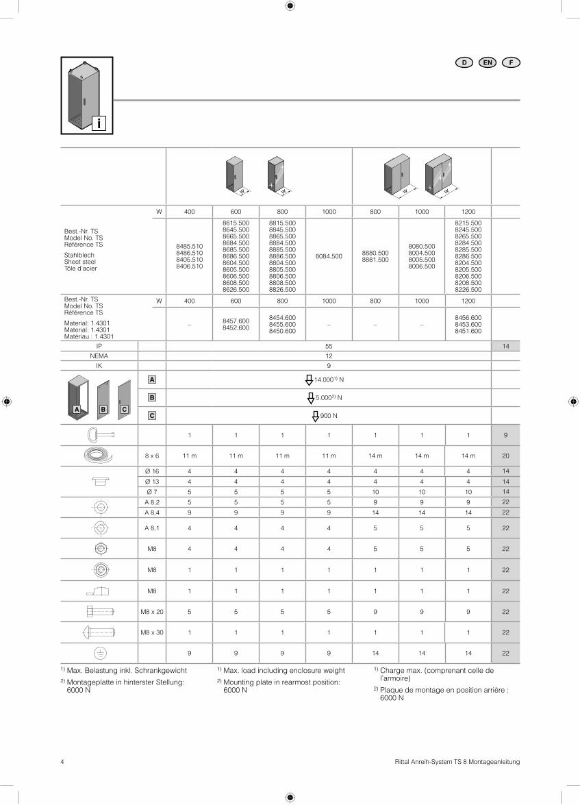
Best.-Nr. TSModel No. TSRéférence TS
StahlblechSheet steelTôle d’acier
W 400 600 800 1000 800 1000 1200
8485.5108486.5108405.5108406.510
8615.5008645.5008665.5008684.5008685.5008686.5008604.5008605.5008606.5008608.5008626.500
8815.5008845.5008865.5008884.5008885.5008886.5008804.5008805.5008806.5008808.5008826.500
8084.5008880.5008881.500
8080.5008004.5008005.5008006.500
8215.5008245.5008265.5008284.5008285.5008286.5008204.5008205.5008206.5008208.5008226.500
Best.-Nr. TSModel No. TSRéférence TS
Material: 1.4301Material: 1.4301Matériau : 1.4301
W 400 600 800 1000 800 1000 1200
–8457.6008452.600
8454.6008455.6008450.600
– – –8456.6008453.6008451.600
IP 55 14
NEMA 12
IK 9
A 14.0001) N
B 5.0002) N
C 900 N
1 1 1 1 1 1 1 9
8 x 6 11 m 11 m 11 m 11 m 14 m 14 m 14 m 20
Ø 16 4 4 4 4 4 4 4 14
Ø 13 4 4 4 4 4 4 4 14
Ø 7 5 5 5 5 10 10 10 14
A 8,2 5 5 5 5 9 9 9 22
A 8,4 9 9 9 9 14 14 14 22
A 8,1 4 4 4 4 5 5 5 22
M8 4 4 4 4 5 5 5 22
M8 1 1 1 1 1 1 1 22
M8 1 1 1 1 1 1 1 22
M8 x 20 5 5 5 5 9 9 9 22
M8 x 30 1 1 1 1 1 1 1 22
9 9 9 9 14 14 14 22
CA B
1) Max. Belastung inkl. Schrankgewicht
2) Montageplatte in hinterster Stellung: 6000 N
1) Max. load including enclosure weight
2) Mounting plate in rearmost position: 6000 N
1) Charge max. (comprenant celle del’armoire)
2) Plaque de montage en position arrière : 6000 N

5Rittal Anreih-System TS 8 Montageanleitung
Hinweise zur Dokumentation/Notes on documentation/Remarques relatives à la documentation
D
Die Montageanleitung richtet sich an alle Personen, die über eine entsprechende Fachausbildung verfügen, um Schalt-schränke normgerecht mit elektrischen, elektronischen, mechanischen oder pneu-matischen Betriebsmitteln auszurüsten, am Bestimmungsort aufzustellen bzw. zu mon-tieren und betriebsfertig anzuschließen.
Die Bedienungsanleitung richtet sich an das Bedienpersonal und entsprechend aus-gebildete Fachkräfte für elektrotechnische und mechanische Instandhaltung.
Mitgeltende UnterlagenFür die hier beschriebenen Schaltschränke existiert die Montage- und Bedienungs-anleitung als Papierdokument dem Gerät bei liegend. Für Schäden, die durch Nichtbeachtung die-ser Anleitungen entstehen, übernehmen wir keine Haftung. Zusätzlich gelten auch die Anleitungen des verwendeten Zubehörs.
CE-KennzeichnungDie Konformitätserklärung nach EN 62 208 steht als Download auf der Homepage von Rittal zur Verfügung.
Aufbewahrung der UnterlagenDiese Anleitung sowie alle mitgeltenden Unterlagen sind Teil des Produktes. Sie müs-sen dem Anlagenbetreiber ausgehändigt werden. Dieser übernimmt die Aufbewah-rung, damit die Unterlagen im Bedarfsfall zur Verfügung stehen.
EN
The assembly instructions are aimed at personnel who have completed cor-responding technical training and are thus qualifi ed to set up enclosures with electri-cal, electronic, mechanical and pneumatic equipment in accordance with applicable standards and to erect, assemble and con-nect such enclosures at the place of use.
The operating instructions are aimed at operating personnel and correspond-ingly trained specialists for electrical and mechanical maintenance.
Other applicable documentsAssembly and operating instructions exist as paper documents for the enclosures described here and are enclosed with the equipment. No liability can be accepted for damage resulting from failure to observe these instructions or the instructions of any acces-sories used.
CE labellingThe declaration of conformity in accordance with EN 62 208 is provided for download on the Rittal website.
Retention of documentsThese instructions and all other applicable documents are inherent parts of the product. They must be handed over to the plant operator. The operator is then responsible for storage such that the documents are readily available when required.
F
La notice de montage s’adresse à toutes les personnes qui possèdent la formation technique suffi sante pour le montage, l’installation sur site et le raccordement d’armoires électriques selon les normes électriques, électroniques, mécaniques et pneumatiques en vigueur.
La notice d’utilisation s’adresse aux opé-rateurs et aux spécialistes formés pour la maintenance électrotechnique et méca-nique.
Autres documents applicablesLa notice de montage et d’utilisation pour les armoires électriques décrites dans le présent document est livrée sous forme papier avec le produit.Nous déclinons toute responsabilité en cas de dommages imputables à la non-obser-vation des instructions contenues dans ces documents. En complément, il faut éga-lement tenir compte des notices pour les accessoires utilisés.
Certifi cation CELa déclaration de conformité selon EN 62 208 peut être téléchargée depuis le site Internet de Rittal.
Conservation des documentsCette notice ainsi que tous les autres docu-ments contractuels font partie intégrante du produit. Ils doivent être remis à l’exploitant de l’installation. Celui-ci les conservera de manière à ce que les documents soient disponibles en cas de besoin.
EN FD

6 Rittal Anreih-System TS 8 Montageanleitung
Hinweise zur Dokumentation/Notes on documentation/Remarques relatives à la documentation
D
Verwendete SymboleBeachten Sie folgende Sicherheits- und sonstige Hinweise in der Anleitung:
Symbol für eine Handlungsanweisung: � Der Blickfangpunkt zeigt an, dass Sie eine Handlung durchführen sollen.
Sicherheits- und andere Hinweise:
Gefahr!Unmittelbare Gefahr für Leib und Leben.
Achtung!Mögliche Gefahr für Produkt und Umwelt.
Hinweis:Nützliche Information und Besonderheiten.
EN
Symbols usedObserve the following safety and other notes in the instructions:
Symbol identifying required actions: � The bullet point indicates an action to be performed.
Safety and other notes:
Danger!Immediate danger to life and limb.
Caution!Potential threat to the product and its environment.
Note:Useful information and special features.
F
Symboles utilisésTenir compte des consignes de sécurité et autres directives contenues dans cette notice :
Symbole indiquant une action à effectuer : � Le pictogramme en caractère gras indique que vous devez exécuter une action.
Consignes de sécurité et autres directives :
Danger !Risque de blessure grave, voire mortelle.
Attention !Danger éventuel pour le produit et l’environnement.
Remarque :Informations utiles et particularités.
EN FD
Sicherheitshinweise/ Safety notes/ Consignes de sécurité
D
Bei der Entwicklung des Anreih-Schranks TS 8 wurden bereits im Konstruktions-stadium sicherheitskritische Punkte über eine Risikobeurteilung nach DIN EN ISO 14121 bewertet und vermieden. Da sich einige wenige Restrisiken nicht ausschließen lassen, sind folgende Hinweise zu beachten.
Gefahr!Unmittelbare Gefahr für Leib und Leben.
� Um ein evtl. Kippen des Schaltschranks in Folge ungleicher Lastverteilung beim Innenausbau zu verhindern, muss dieser unbedingt am Boden verschraubt werden. Eine zusätzliche Fixierung an einer Wand kann mittels Wandhalter erfolgen.
� Die Drehmomentangaben zum Befestigen von Montageplatte und weiteren Innenaus-bauteilen sind unbedingt einzuhalten.
� Konstruktiv ist ein automatischer Poten-zialausgleich von Rückwand, Dachblech, Seitenwand (Zubehör) und Tür zum Grund-gehäuse und den Boden blechen zum Grundgehäuse berücksichtigt. Zusätzlich sind diese Flachteile mit Erdungsbolzen bzw. Durchzügen für Erdungsschrauben ausgestattet, um einen systemgerechten Potenzialausgleich vorzunehmen, wenn dies ausbaubedingt notwendig ist.
EN
Safety-critical points were already assessed and eliminated by way of a risk assess-ment to DIN EN ISO 14121 at the design stage of development of the TS 8 baying enclosure. As certain residual risks cannot be excluded, the following notes must be observed at all times.
Danger!Immediate danger to life and limb.
� It is imperative to bolt the enclosure to the fl oor to prevent possible tilting due to an uneven load distribution when installing the components. An additional wall fi xing can be provided by way of a wall bracket.
� Observe all tightening torques specifi ed for the fi xing of mounting plates and other installation parts.
� The design provides for automatic potential equalisation between the rear panel, roof plate, side panel (accesso-ries), door and the basic enclosure, as well as between the gland plates and the basic enclosure. These panel parts are additionally provided with earthing bolts or through-holes for earthing screws to per-mit system-specifi c potential equalisation where this is required by the installation.
F
Les points critiques relatifs à la sécurité ont été traités et éliminés lors de la conception et de la construction de l’armoire juxtapo-sable TS 8 grâce à une analyse des risques selon la norme DIN EN ISO 14121. Les consignes suivantes doivent être respectées car il n’est pas possible d’exclure certains risques résiduels peu nombreux.
Danger !Risque de blessure grave, voire mortelle.
� Il faut absolument visser l’armoire électrique au sol pour éviter qu’elle ne bascule si la répartition de la charge de son équipement est inégale. Une fi xation complémentaire au mur est possible grâce aux fi xations murales.
� Les indications sur les couples de serrage pour la fi xation de la plaque de montage et des autres équipements intérieurs doivent absolument être respectées.
� Une équipotentialité automatique du pan-neau arrière, du toit en tôle, du panneau latéral (en accessoires) et de la porte par rapport au châssis et des plaques passe-câbles par rapport au châssis est prévue par la conception de l’armoire. Ces pièces plates sont de plus équipées de boulons de mise à la terre ou de réservations pour les vis de mise à la terre pour réaliser une équipotentialité au niveau du système si cela est nécessaire.
EN FD

7Rittal Anreih-System TS 8 Montageanleitung
Montage und Aufstellung/Assembly and siting/Montage et implantation
D
Anforderungen an den AufstellortBeachten Sie die nachfolgenden allgemei-nen Hinweise bei Montage und Bedienung des Schaltschranks:
Vor der Montage ist zu beachten, dass: � der Aufstellort frei von starkem Schmutz und Feuchtigkeit ist.
� die Umgebungstemperatur am Aufstellort nicht höher als +80 °C ist.
� die Umgebungstemperatur am Aufstellort nicht niedriger als –20 °C ist.
� der Schaltschrank nach dem Aufstellen waagrecht steht. Eventuelle Unebenheiten am Aufstellort können mittels Nivellier füßen ausgeglichen werden.
� IP 55 nach EN 60 529 in Verbindung mit Seitenwänden verschraubt.
Hinweise zur Montage
Gefahr!Unmittelbare Gefahr für Leib und Leben.
� Halten Sie die auf Seite 4 vorgegebenen Belastungsangaben ein.
� Halten Sie alle vorgegebenen Dreh-momentangaben ein. Ein Über- bzw. Unterschreiten der in dieser Anleitung vorgegebenen Anzugsdrehmomente kann zu Anlagenschäden oder zu schweren bis hin zu tödlichen Verletzungen führen.
� Vermeiden Sie nicht notwendige Öff-nungen am Schaltschrank. Jede nicht sorgfältig eingebrachte und abgedichtete Öffnung kann zu einer Reduzierung der Schutzart führen.
� Die bestückte Montageplatte ist für den Transport zu sichern! Zubehör, siehe HB 33, Seite 632 – 633.
Hinweise zur Bedienung
� Der Vierpunkt-Stangenverschluss ist leichtgängig und wird ausschließlich über den Verschluss oder einen nachträglich eingebauten Komfortgriff bedient. Ein zusätzliches Zudrücken der Tür ist nicht notwendig und kann zu Quetschverlet-zungen an Hand oder Finger führen.
� Vermeiden Sie unnötig langes Offenstehen der Türen, da Staub, Luftfeuchte oder mit Schadstoffen belastete Luft in den Schalt-schrank eindringen kann.
� Überprüfen Sie nach Arbeiten am Schalt-schrank, dass die Tür ordnungsgemäß verschlossen ist.
EN
Installation requirementsObserve the following general notes on assembly and operation of the enclosure:
Before assembly, ensure that: � the site is free from excessive dirt and moisture.
� the ambient temperature at the site is not higher than +80 °C.
� the ambient temperature at the site is not lower than –20 °C.
� the enclosure stands level after erection. Any unevenness at the site can be com-pensated by way of levelling feet.
� IP 55 to IEC 60 529 when fi tted with side panels, screw-fastened.
Notes on assembly
Danger!Immediate danger to life and limb.
� Observe the load specifi cations given on page 4.
� Observe all specifi ed tightening torques. If screws or bolts are tightened with torques greater or less than those specifi ed in these instructions, this may result in dam-age and serious or even fatal injuries.
� Avoid all unnecessary openings in the enclosure. Openings which are not made and sealed properly may reduce the degree of protection.
� The equipped mounting plate must be secured for transportation! Accessories, see Cat. 33, page 632 – 633.
Notes on operation
� The four-point locking rod guarantees ease of movement and is actuated exclusively by way of the closure or a retrofi tted com-fort handle. It is not necessary to press the door closed; this could lead to crushing injuries to hands or fi ngers.
� Avoid leaving the door open for longer periods than necessary, as dust, humid-ity and contaminated air can enter the enclosure.
� Check that the enclosure door is properly closed after working on the enclosure.
F
Exigences vis à vis du site d’implantationRespecter les consignes générales sui-vantes lors du montage et de l’utilisation de l’armoire électrique :
Avant le montage, il faut s’assurer que : � le site d’implantation soit exempt d’un excès de saleté et d’humidité.
� la température ambiante sur le site d’implantation ne soit pas supérieure à +80 °C.
� la température ambiante sur le site d’im-plantation ne soit pas inférieure à –20 °C.
� l’armoire électrique soit droite après son implantation. Les éventuelles irrégularités du sol du site d’implantation peuvent être corrigées grâce aux pieds de nivellement.
� IP 55 selon EN 60 529 si équipé de pan-neaux latéraux vissé.
Instructions relatives au montage
Danger !Risque de blessure grave, voire mortelle.
� Veuillez respecter les indications de charge qui fi gurent en page 4.
� Veuillez respecter les indications sur les couples de serrage. Des couples de serrage supérieurs ou inférieurs aux indi-cations de cette notice peuvent provoquer des dommages sur l’installation ou des blessures graves, voire mortelles.
� Eviter toutes les ouvertures inutiles dans l’armoire électrique. Chaque ouverture qui n’est pas soigneusement étanchéifi ée peut conduire à la réduction de l’indice de protection.
� La plaque de montage équipée doit être sécurisée lors d’un transport ! Accessoires, voir CG33, pages 632 – 633.
Consignes d’utilisation
� La fermeture à crémone à quatre points fonctionne aisément et doit être action-née exclusivement à l’aide du dispositif de fermeture ou de la poignée confort (disponible en accessoires). Une poussée supplémentaire de la porte n’est pas nécessaire car elle peut conduire à des blessures par écrasement des mains ou des doigts.
� Eviter l’ouverture inutile des portes de l’armoire électrique sur une durée pro-longée car la poussière, l’humidité ou de l’air chargé de produits nocifs peuvent y pénétrer.
� Après les travaux, vérifi er que les portes de l’armoire électrique soient correctement fermées.
EN FD

8 Rittal Anreih-System TS 8 Montageanleitung
2 4
2 4
2 4
1 2.1
2.2 3.1
5.1 5.2
TX30
1
1
1
1
3
3
3
3
5
5
5
5
EN FD
3.2
2 4
4.1
3.3
MD = 9 Nm
M6 x 12
4.2
M6 x 12
MD = 9 Nm
9Rittal Anreih-System TS 8 Montageanleitung
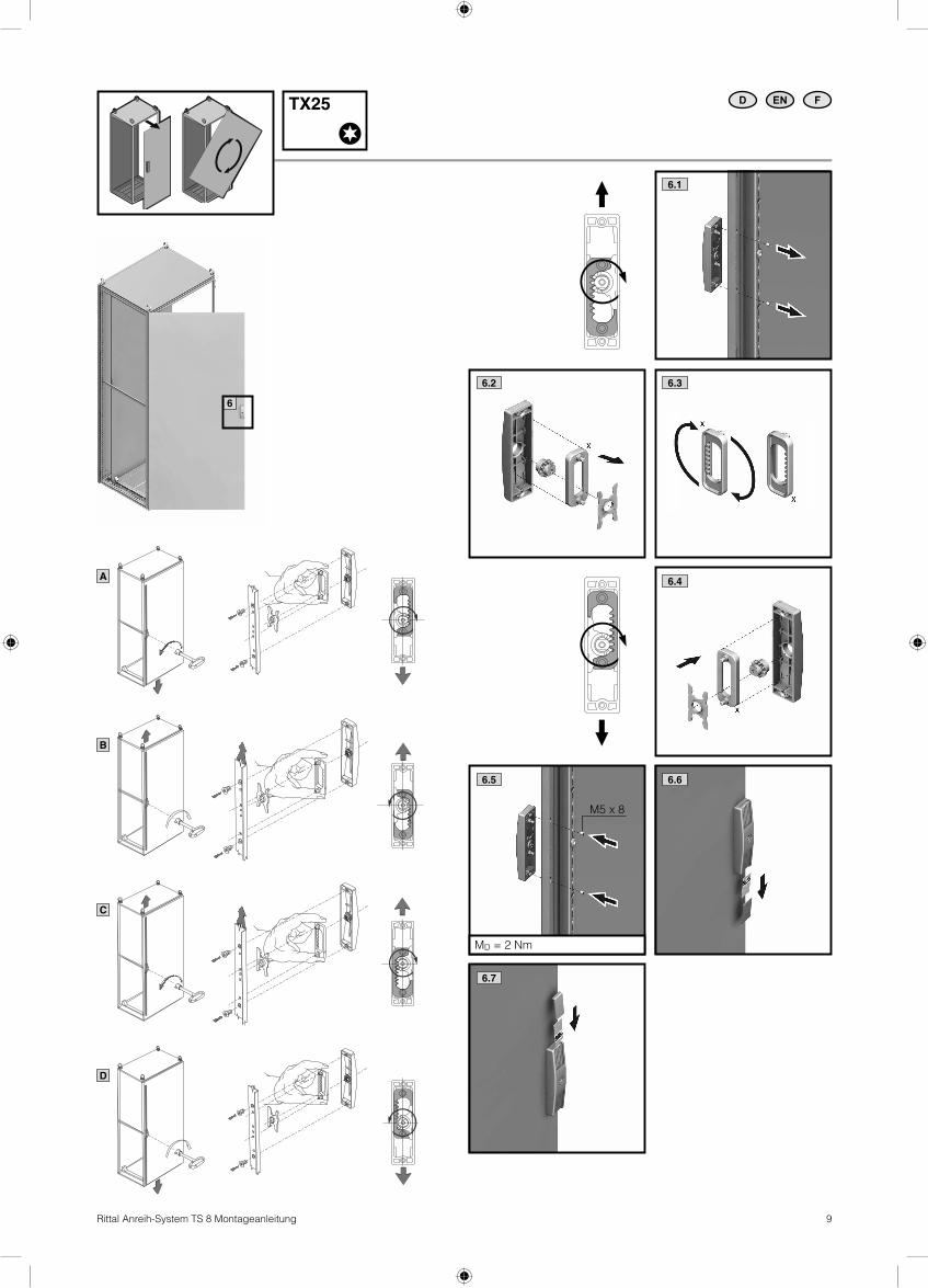
6.1
6.7
6.2 6.3
6.4
EN FDTX25
6.5
MD = 2 Nm
6.6
6
A
B
C
D
M5 x 8

10 Rittal Anreih-System TS 8 Montageanleitung
1.1 1.2
SW13 EN FD
2.1 2.2
MD = 5 Nm
1.21.1
2.22.1
1.3
TX30 EN FD
2.3
MD = 5 Nm
M6 x 9
400/600/800 (8 x) 1000/1200 (10 x)
1 2
1 2
1 2
1 2
1 2
1 2
1 2
1 2
1 2 1 2
1 2 1 2
1 2 1 2

11Rittal Anreih-System TS 8 Montageanleitung
1.21)1.1
2.1
1.3
TX25 EN FD
2.21)
MD = 5 Nm
M5,5 x 13
2.3
MD = 10 – 35 Nm
1) Zusätzlich bei Breite 1000/1200 / Additionally for width 1000/1200 / En complément pour une largeur 1000/1200
1 2
1 2
1 2
1 2

12 Rittal Anreih-System TS 8 Montageanleitung
1
1
2
2
X + 75
50
75
X
1.1
1.7
1.2
2.32.2
TX25 TX30 mm EN FD
1.82.6
1
2
2.4
2
1
1.4
2
1
1.5
21
3
1.3
2.1
1
2
2.55,5 x 13
MD = 5 Nm
1.6
2
1
TransportsicherungShipping braceSécurité pour le
1.9
MD = 9 Nm

13Rittal Anreih-System TS 8 Montageanleitung
1
1
2
2
1.1
1.2
1.3
TX25 TX30
2.2
25
50
2.4
EN FD
1.8
1.7
Tipp/Tip/Astuce
2.31.6
Montageplatteneinbau in hinterster Stellung
Fitting the mounting plate in the rearmost position
Installation de la plaque de montage en position arrière
2.1
1
2
1.5
12
3
1
2
1.4
2
1
2
1
TransportsicherungShipping braceSécurité pour le transport
1.9
MD = 9 Nm

14 Rittal Anreih-System TS 8 Montageanleitung
1.2
TX25/30
Drei Beispiele aus einer Vielzahl von MöglichkeitenDie Grafi ken zeigen drei TS 8 Beispiele für die Positionierung von Kabeleinführungsblechen anstelle von Segmenten der serien-mäßigen dreigeteilten Bodenbleche. So ist eine Positionierung passend zur Montageplatte möglich. Durch die Schranksymme-trie sind die Kabeleinführungsbleche analog der Bodenbleche bei entsprechenden Maßen auch in Schranktiefe, rechts und links, einsetzbar.
Three examples from the multitude of possibilitiesThe illustrations here show three examples for the fi tting of cable entry plates in place of the standard three-part gland plates of the TS 8 enclosure. Positioning can thus be matched to the mounting plate. The symmetrical enclosure design permits the cable entry plates to be installed on either the right or left, in the same way as the gland plates – variation in the enclosure depth is similarly possible with appropriate dimensions.
Trois exemples représentatifsLes schémas montrent trois exemples de TS 8 pour le placement des plaques d’entrées de câbles en remplacement des segments des plaques passe-câbles de série en trois parties. Le placement en fonction de la plaque de montage est ainsi possible. Grâce à la symétrie de l’armoire, les plaques d’entrées de câbles, comme les plaques passe-câbles, peuvent également être installées, à tailles correspondantes, dans la profondeur de l’armoire, à droite ou à gauche.
EN FD
1.3
HB 33, 701
1.1
8 x 6
2.3
Ø 7
Edelstahl 1.4301Stainless steel 1.4301Acier inoxydable 1.4301
Ø 16
Ø 13
IP
1
1
12
2
1
A B
C
B
C
A
2.2
MD (min.) = 1,5 NmMD (max.) = 2,5 Nm
2.1
8 x 6
1.4
M8 x 12
MD = 9 Nm
1.51)
M5,5 x 13
MD = 5 Nm
2.3
Stahlblech/ Sheet steel/Tôle d’acier
Ø 7
1) Zusätzlich bei Breite 1000/1200 / Additionally for width 1000/1200 / En complément pour une largeur 1000/1200
mm
15Rittal Anreih-System TS 8 Montageanleitung
1.1
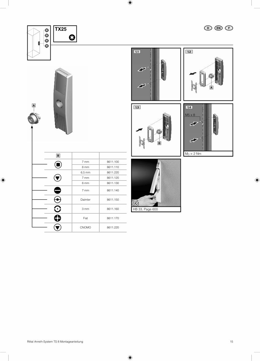
EN FDTX25
B
7 mm 8611.100
8 mm 8611.110
6,5 mm 8611.220
7 mm 8611.120
8 mm 8611.130
7 mm 8611.140
Daimler 8611.150
3 mm 8611.160
Fiat 8611.170
CNOMO 8611.220
HB 33, Page 600
1.4
MD = 2 Nm
A
1.2
A
1.3
B
M5 x 8

16 Rittal Anreih-System TS 8 Montageanleitung
1
1
1
1
180°1.1 1.2
1.3
1.5
1.7
1.9
1.8
TX30
ø 8.5
FarbeColourCouleur
1 x 8800.7101) 2 x 8800.7101) RAL 7035
1 x 8800.190 2 x 8800.190 RAL 7035
1 x 8800.030 2 x 8800.030 RAL 7032
1 x 8800.230 2 x 8800.230 RAL 8019
1 x 8800.950 2 x 8800.950 RAL 9005
1 x 8701.180 2 x 8701.180Matt vernickelt
Matt nickel-platedNickelé mat
1) 900 N
EN FD
1.4
M6 x 12
MD = 9 Nm
1.6
MD = 5 Nm
M5 x 8
SW8 mm
17Rittal Anreih-System TS 8 Montageanleitung
13 87
4
2
9
13
14
7
3
1
A
B
C
D
E
10
5
6
8
12713 11
8
E
6
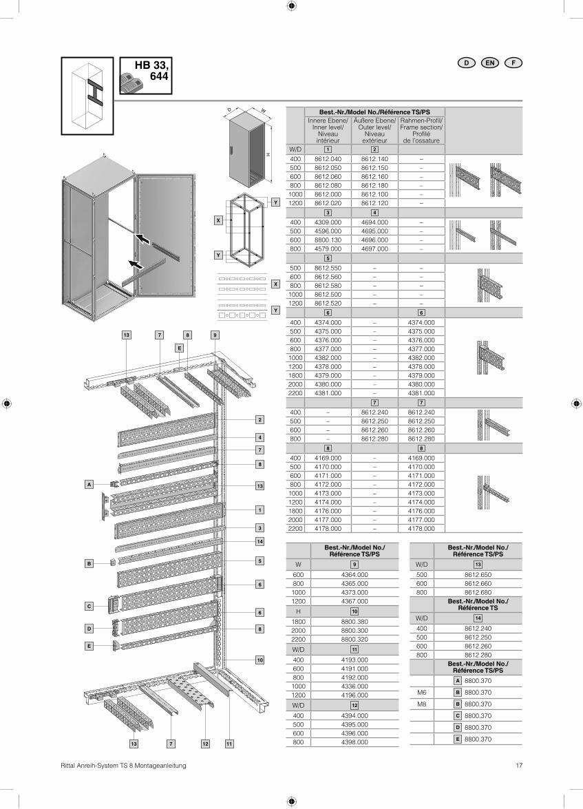
Best.-Nr./Model No./Référence TS/PS
W 9
600 4364.000
800 4365.000
1000 4373.000
1200 4367.000
H 10
1800 8800.380
2000 8800.300
2200 8800.320
W/D 11
400 4193.000
600 4191.000
800 4192.000
1000 4336.000
1200 4196.000
W/D 12
400 4394.000
500 4395.000
600 4396.000
800 4398.000
Best.-Nr./Model No./Référence TS/PS
W/D 13
500 8612.650
600 8612.660
800 8612.680
Best.-Nr./Model No./Référence TS
W/D 14
400 8612.240
500 8612.250
600 8612.260
800 8612.280
Best.-Nr./Model No./Référence TS/PS
8800.370
M6 8800.370
M8 8800.370
8800.370
8800.370
8800.370
A
B
B
C
D
E
D
H
W
EN FDHB 33, 644
Best.-Nr./Model No./Référence TS/PS
Innere Ebene/Inner level/
Niveau intérieur
Äußere Ebene/Outer level/
Niveau extérieur
Rahmen-Profi l/Frame section/
Profi lé de l’ossature
W/D 1 2
400 8612.040 8612.140 –
500 8612.050 8612.150 –
600 8612.060 8612.160 –
800 8612.080 8612.180 –
1000 8612.000 8612.100 –
1200 8612.020 8612.120 –
3 4
400 4309.000 4694.000 –
500 4596.000 4695.000 –
600 8800.130 4696.000 –
800 4579.000 4697.000 –
5
500 8612.550 – –
600 8612.560 – –
800 8612.580 – –
1000 8612.500 – –
1200 8612.520 – –
6 6
400 4374.000 – 4374.000
500 4375.000 – 4375.000
600 4376.000 – 4376.000
800 4377.000 – 4377.000
1000 4382.000 – 4382.000
1200 4378.000 – 4378.000
1800 4379.000 – 4379.000
2000 4380.000 – 4380.000
2200 4381.000 – 4381.000
7 7
400 – 8612.240 8612.240
500 – 8612.250 8612.250
600 – 8612.260 8612.260
800 – 8612.280 8612.280
8 8
400 4169.000 – 4169.000
500 4170.000 – 4170.000
600 4171.000 – 4171.000
800 4172.000 – 4172.000
1000 4173.000 – 4173.000
1200 4174.000 – 4174.000
1800 4176.000 – 4176.000
2000 4177.000 – 4177.000
2200 4178.000 – 4178.000
X
Y
Y
X
Y
18 Rittal Anreih-System TS 8 Montageanleitung
1.21.1
3.2
1.3
TX30 EN FD
4
5.1 5.3
MD = 5 Nm
M6 x 9
5.2
1 3
3.12
4
2 5
2 5
3.3
M6 x 9
MD = 5 Nm
2 Alternative
1 3
M6 x 9
M5 x 8
MD = 9 Nm MD = 5 Nm
SW8
19Rittal Anreih-System TS 8 Montageanleitung
1
3
2
TX30 EN FD
4
MD = 5 Nm
M6 x 10
1 3
2 4
M5 x 10
MD = 3 NmMD = 9 Nm
M8
M8
SW8/13

20 Rittal Anreih-System TS 8 Montageanleitung
A A
C C
E E
B B
D D
F F
2
blaubluebleu
1
TX30 EN FD
1 8 x 6
untenbottomau-dessous
Möglichkeiten der AnreihungBaying optionsPossibilités de juxtaposition
VE (St.)Packs ofUE (p.)
Best.-Nr./Model No./Référence
TS
A Anreih-Schnellverbinder, einteilig/Quick-fi t baying clamp, one-piece/Attache rapide de juxtaposition en une seule pièce 6 8800.500
B Anreih-Schnellverbinder, dreiteilig/Quick-fi t baying clamp, three-piece/Attache rapide de juxtaposition en trois parties 6 8800.590
C Anreihzwinge horizontal/Baying clamp, horizontal/Crampon de juxtaposition horizontal 4 8800.400
D Anreihzwinge vertikal für TS/TS/Baying clamp, vertical for TS/TS/Crampon de juxtaposition vertical pour TS/TS 6 8800.410
E Anreihzwinge vertikal für TS/PS/Baying clamp, vertical for TS/PS/Crampon de juxtaposition vertical pour TS/PS 6 8800.420
F Anreihverbinder außen/Baying connector, external/Attache de juxtaposition extérieure 6 8800490
A
AC
D
E
F
B
IP!
2
8 x 6 x 6000

21Rittal Anreih-System TS 8 Montageanleitung
H H I I
K KJ J
L L
G G
TX30 EN FD
Möglichkeiten der Transport-AnreihungTransport baying options Options de juxtaposition pour le transport
VE (St.)Packs ofUE (p.)
Best.-Nr./Model No./Référence
TS
G Anreihwinkel für TS/TS/Angular baying bracket for TS/TS/Equerre de juxtaposition pour TS/TS 4 8800.430
H Anreihlasche für TS/TS und TS/PS/Baying bracket for TS/TS and TS/PS/Patte de juxtaposition pour TS/TS et TS/PS 4 4582.500
I Kombiwinkel/Combination angle/Equerre combinée 4 4540.000
JAnreihbefestigung vertikal für TS/TS mit Trennwand/Baying attachment, vertical, for TS/TS with divider panel/Fixation de juxtaposition verticale pour TS/TS avec cloison
8 8800.470
K Anreihbefestigung vertikal für TS/TS/Baying attachment, vertical, for TS/TS/Fixation de juxtaposition verticale pour TS/TS 6 8800.670
LAnreihverbinder für Montage Rücken an Rücken/Baying clamp, for back-to-back mounting/Attache de juxtaposition pour armoires montées dos à dos
4 8800.170
G
H
H
22 Rittal Anreih-System TS 8 Montageanleitung
2
2
2
2
6
1 3
1 3
4 5
4 5
4
SW13
1 2 3 4 5 6
M8 x 30 1 – – – – –
M8 x 20 – – – 4/8 1 –
Ø 8,2 – – – 4/8 1 –
M8 1 1/2 1 – – 1
M8 1 – – – – –
M8 – – – – 1 –
A 8,4 1 1/2 1 4/8 1 1
A8 1 1/2 1 – – 1
1 1/2 1 4/8 1 1
4
MD = 10 – 12 Nm
EN FD
1
MD = 10 – 12 Nmlth2 x TK = 92,3 x 10⁶ A2 s
M8 x 30
M8
2
MD = 8 – 10 Nm
M8
3
MD = 8 – 10 Nm
M8
HB 33, 689
MD = 10 – 12 Nm
M8 x 205
MD = 8 – 10 Nm
6
M8 x 20
M8

23Rittal Anreih-System TS 8 Montageanleitung
1
1
1
1
F
¼ F¼ F
¼ F¼ F
F
F
90° 45° 60°
F 13.600 N 4.800 N 6.400 N Max. 14.000 N
SZ 4568.000, SZ 4568.500
EN FD
EN FD

24 Rittal Anreih-System TS 8 Montageanleitung
EN FD
EN FD
Dynamische Belastung
Dynamic loads
Charge dynamique

25Rittal Anreih-System TS 8 Montageanleitung
QS [W]
D
H
G
W
F
Best.-Nr. SEModel No. SERéférence SE
Tu = 25 °CTi = 45 °CPv = 0 W
Schrank/Enclosure/
Armoire
Montageplatte/Mounting plate/
Plaque de montage
StahlblechSheet steelTôle d’acier
Material: 1.4301Material: 1.4301Matériau : 1.4301
W (T = 20 K) W mm H mm D mm F mm G mmStärke
ThicknessEpaisseur
8615.500 – 308 249 276 223 249 600 1200 500 499 1096 3
8815.500 – 370 302 328 275 302 800 1200 500 699 1096 3
8215.500 – 496 407 433 380 407 1200 1200 500 1099 1096 3
8645.500 – 351 283 314 253 283 600 1400 500 499 1296 3
8845.500 – 422 342 373 311 342 800 1400 500 699 1296 3
8245.500 – 564 459 490 428 459 1200 1400 500 1099 1096 3
8665.500 – 395 317 352 282 317 600 1600 500 499 1496 3
8865.500 – 473 382 417 347 382 800 1600 500 699 1496 3
8265.500 – 631 511 546 476 511 1200 1600 500 1099 1496 3
8684.500 – 393 314 346 282 314 600 1800 400 499 1696 3
8884.500 8454.600 477 382 414 350 382 800 1800 400 699 1696 3
8084.500 – 561 450 481 418 450 1000 1800 400 899 1696 3
8080.500 – 561 450 481 418 450 1000 1800 400 899 1696 3
8284.500 8456.600 644 517 549 486 517 1200 1800 400 1099 1696 3
8485.510 – 352 280 320 241 280 400 1800 500 – – –
8685.500 8457.600 438 351 391 312 351 600 1800 500 499 1696 3
8885.500 – 525 422 462 382 422 800 1800 500 699 1696 3
8880.500 8455.600 525 422 462 382 422 800 1800 500 699 1696 3
8285.500 8453.600 698 564 603 524 564 1200 1800 500 1099 1696 3
8486.510 – 393 314 362 267 314 400 1800 600 – – –
8686.500 – 483 388 436 341 388 600 1800 600 499 1696 3
8886.500 – 573 462 510 414 462 800 1800 600 699 1696 3
8881.500 – 573 462 510 414 462 800 1800 600 699 1696 3
8286.500 – 752 610 657 562 610 1200 1800 600 1099 1696 3
8604.500 – 433 345 380 310 345 600 2000 400 499 1896 3
8804.500 – 524 419 454 384 419 800 2000 400 699 1896 3
8004.500 – 616 493 528 458 493 1000 2000 400 899 1896 3
8204.500 – 708 567 602 532 567 1200 2000 400 1099 1896 3
8405.510 – 387 308 352 264 308 400 2000 500 – – –
8605.500 – 482 385 429 341 385 600 2000 500 499 1896 3
8805.500 – 576 462 506 418 462 800 2000 500 699 1896 3
8005.500 – 671 539 583 495 539 1000 2000 500 899 1896 3
8205.500 – 766 616 660 572 616 1200 2000 500 1099 1896 3
8406.510 – 433 345 398 292 345 400 2000 600 – – –
8606.500 8452.600 531 425 478 372 425 600 2000 600 499 1896 3
8806.500 8450.600 628 505 558 452 505 800 2000 600 699 1896 3
8006.500 – 726 585 638 532 585 1000 2000 600 899 1896 3
8206.500 8451.600 824 665 718 612 665 1200 2000 600 1099 1896 3
8608.500 – 628 505 576 435 505 600 2000 800 499 1896 3
8808.500 – 732 591 662 521 591 800 2000 800 699 1896 3
8208.500 – 940 764 834 693 764 1200 2000 800 1099 1896 3
8626.500 – 578 462 520 404 462 600 2200 600 499 2096 3
8826.500 – 684 548 606 490 548 800 2200 600 699 2096 3
8226.500 – 895 721 779 663 721 1200 2200 600 1099 2096 3
EN FD
Technische Daten/Technical data/Caractéristiques techniques

26 Rittal Anreih-System TS 8 Montageanleitung
Hinweise zur Wartung/Notes on maintenance/Remarques relatives à l’entretien
D
Der Wartungsplan ist empfohlen für alle Anreih-Schränke TS 8.
WartungsintervallDie Wartung muss regelmäßig in Abhän-gigkeit der Einsatz- und Umgebungs-bedingungen, mindestens einmal jährlich durchgeführt und entsprechend dokumen-tiert werden.
Art und Umfang der durchzuführenden Arbeiten: � Die Scharniere der Türen werden auf Leichtgängigkeit überprüft und mit einem geeigneten, wasserfreien Schmiermittel eingesprüht.
� Das Schloss wird auf Leichtgängigkeit überprüft. Alle beweglichen Verschluss-teile werden mit einem geeigneten, wasserfreien Schmiermittel eingesprüht.
� Dichtungen im Andruckkantenbereich müssen bei Beschädigung komplett ersetzt werden. Bei Beschädigung der Dichtung außerhalb der Andruckkanten ist i. d. R. noch eine ausreichende Dichtwir-kung vorhanden.
� Um Beschädigungen durch temperatur-bedingtes Anfrieren der Dichtungen zu verhindern, können übliche Mittel wie Talkum, Vaseline oder Wachse eingesetzt werden. Alle Komponenten und Oberfl ä-chen werden auf äußere Beschädigungen untersucht.
� Stahlschränke werden zusätzlich auf Korrosionsspuren untersucht.Eventuelle Beschädigungen werden wie folgt repariert:
– Kleinfl ächige Schäden, die nur einen Teil der Oberfl äche betreffen (z. B. Kratzer): Oberfl äche an der beschädigten Stelle leicht anschleifen und alle Korrosions-spuren sowie alle Verschmutzungen entfernen. Je nach Größe der Beschä-digung entweder mit einem Lackstift, einem Pinsel oder mit der Lackspray-dose den Rittal Ausbesserungslack auf-bringen (alternativ: 2K-PUR Acryllack)
– Großfl ächige Schäden: Oberfl äche gleichmäßig abreiben und mit Testbenzin reinigen; anschließend gesamte Fläche mit Rittal Ausbesse-rungslack überlackieren (alternativ: 2K-PUR Acryllack).
� Bei Edelstahlschränken werden Ober-fl ächenbeschädigungen wie Kratzer durch eine Oberfl ächenpolitur beseitigt.
EN
The maintenance plan is recommended for all TS 8 baying enclosures.
Maintenance intervalMaintenance must be performed at regular intervals depending on use and ambient conditions, but in any case at least once annually. All maintenance work must be documented accordingly.
Nature and extent of the work to be performed: � The hinges of the doors are to be checked for ease of movement and sprayed with a suitable, water-free lubricant.
� The lock is to be checked for ease of movement. All moving closure parts are to be sprayed with a suitable, water-free lubricant.
� Seals must be replaced as a whole if damaged in the area of the contact edges. If the seal is damaged away from the contact edges, the sealing effect will still be suffi cient as a rule.
� Common agents such as talcum, vaseline or wax can be used to prevent damage due to seals freezing in cold conditions. All components and surfaces are to be examined for external damage.
� Steel enclosures must also be examined for traces of corrosion. Any damage is to be repaired as follows:
– Damage affecting small areas and only part of the surface (e.g. scratches): Lightly sand off the surface around the damaged area and remove all traces of corrosion and contamination. Depend-ing on the extent of the damage, apply Rittal touch-up paint either with a pen, a brush or from a spray can (alternatively: two-component PUR acrylic paint)
– Damage affecting large areas: Rub the surface off uniformly and clean with white spirit; then paint over the entire surface with Rittal touch-up paint (two-component PUR acrylic paint).
� Surface damage to stainless steel enclo-sures, e.g. scratches, can be rectifi ed by polishing.
F
Le calendrier d’entretien est conseillé pour toutes les armoires juxtaposables TS 8.
Périodicité d’entretienL’entretien doit être réalisé périodiquement en fonction des conditions d’utilisation et ambiantes, au moins une fois par an, et il doit être consigné en conséquence.
Type et nature des travaux à effectuer : � Vérifi er le bon fonctionnement des char-nières des portes et les vaporiser à l’aide d’un lubrifi ant sans eau adapté.
� Vérifi er le bon fonctionnement de la serrure. Vaporiser un lubrifi ant sans eau adapté sur toutes les parties mobiles du système de fermeture.
� En cas de détérioration, remplacer com-plètement les joints situés dans la zone des arêtes d’étanchéité. L’étanchéité est en règle générale encore suffi sante en cas de détérioration du joint situé hors des arêtes d’étanchéité.
� Pour prévenir une éventuelle détérioration des joints par le gel, ceux-ci peuvent être enduits de produits courants comme le talc, la vaseline ou la cire. Vérifi er la pré-sence de détériorations externes sur tous les composants et sur toutes les surfaces.
� Vérifi er de plus la présence de traces de corrosion sur les armoires électriques. Les éventuelles détériorations sont réparées comme suit :
– Détériorations de petite taille qui ne concernent qu’une partie de la surface (par exemple rayures) : Poncer légèrement la surface endom-magée et supprimer toutes les traces de corrosion et salissures. Selon l’impor-tance de la détérioration, appliquer la laque de réparation Rittal à l’aide d’un crayon de retouche, d’un pinceau ou d’un aérosol (vous pouvez également utiliser la laque acrylique 2K-PUR).
– Détériorations de grande taille : Poncer uniformément la surface et la nettoyer avec du white spirit, puis appliquer la laque de réparation Rittal sur toute la surface (vous pouvez égale-ment utiliser la laque acrylique 2K-PUR).
� Sur les armoires en acier inoxydable, les détériorations superfi cielles comme les rayures sont éliminées à l’aide d’un produit pour polir les surfaces.
EN FD

27Rittal Anreih-System TS 8 Montageanleitung
Garantie/Warranty/Garantie
Es gelten die in den Verkaufs- und Lieferbedingungen der jeweiligen Rittal Vertriebs- und Tochtergesellschaften genannten Bedingungen.
The terms of sale and delivery of the individual Rittal sales agencies and subsidiaries apply.
Les conditions stipulées dans les conditions de vente et de livraison des représentations et des fi liales correspondantes de Rittal sont contractuelles.
EN FD
Kundendienstadressen/Customer service addresses/Adresses des services après-vente
Unsere 5 strategischen Service-HUBs in Deutschland, den USA, Brasilien, China und Indien dienen als zentrale Knotenpunkte für die jeweilige Region. Diese weltweite Vernetzung ermöglicht eine schnelle und effi ziente Serviceabwicklung.
Our 5 strategic service hubs in Germany, the USA, Brazil, China and India serve as central nodes for the respective region. This worldwide network permits rapid and effi cient processing of all service requests.
Nos 5 plate-formes après-vente stratégiques en Allemagne, aux USA, au Brésil, en Chine et en Inde constituent les bases de référence pour les autres pays. Ce réseau mondial permet un service après-vente rapide et effi cace.
Headquarter DeutschlandHeadquarters GermanySiège en AllemagneRITTAL GmbH & Co. KGAuf dem StützelbergD-35745 HerbornPhone +49(0)2772 505-1855Fax +49(0)2772 505-1850E-mail: [email protected]
Service-HUB USAService HUB USAPlateforme de service aux Etats-UnisRITTAL Corporation801 State Route 55 Dock 25Urbana, OH 43078Phone +1 800 477 4000, option 3E-mail: [email protected]
Service-HUB IndienService HUB IndiaPlateforme de service en IndeRITTAL India Pvt. Ltd.Nos. 23 & 24, KIADBIndustrial Area VeerapuraDoddaballapur-561 203 Bengaluru District Phone +91 (80) 22890792Fax +91 (80) 7623 343E-mail: [email protected]
Service-HUB BrasilienService HUB BrazilPlateforme de service en BrésilRITTAL Sistemas Eletromecânicos Ltda.Av. Cândido Portinari, 1174Vila Jaguara05114-001 São Paulo - SP Phone +55 (11) 3622 2361Fax +55 (11) 3622 2399E-mail: [email protected]
Service-HUB ChinaService HUB ChinaPlateforme de service en ChineRITTAL Electro-Mechanical Technology Co. Ltd.No. 1658, Minyi RoadSongjiang DistrictShanghai, 201612Phone +86 21 5115 7799-213Fax +86 21 5115 7788E-mail: [email protected]
EN FD
RITTAL GmbH & Co. KG
Postfach 1662 · D-35726 Herborn
Phone + 49(0)2772 505-0 · Fax + 49(0)2772 505-2319
E-Mail: [email protected] · www.rittal.de
� Enclosures
� Power distribution
� Climate control
� IT infrastructure
� Software & services
10.2
012/A
2088808TS
73