M52 Connectors Specification - Sibalco · All dimensions in mm. 118 1.27 mm (.050") P ITCH Archer...
6
117 All dimensions in mm. www.harwin.com 1.27mm (.050") PITCH M52 Connectors Specification Materials Mouldings: High Temperature Plastic UL94V-0 Contacts: Copper Alloy Finish: Gold Electrical Current rating: 1A per contact Voltage proof: 500V AC, 1000V DC for 1 minute Contact resistance: 30 mΩ max Insulation resistance: 1000 MΩ min Environmental Operating temperature: -40°C to +105°C Solderability: 245°C for 5 seconds Soldering heat resistance: 260°C for 5 seconds Mechanical Durability: 300 operations Insertion force (max): M52-500, 510: 1.0N per contact Others: 1.5N per contact Withdrawal force (min): M52-500, 510: 0.12N per contact Others: 0.1N per contact Vibration sensitivity: 50-2000Hz, 3.13G, 45 minutes duration Shock severity: 294m/s 2 (30G) for 11ms FEMALE MALE VERTICAL PC TAIL (4.6mm height) VERTICAL PC TAIL (8.5mm height) VERTICAL SMT VERTICAL PC TAIL M52-500 M52-510 M52-040023VXX45 M52-040023WXX45 M52-501 M52-511 M52-040023VXX45 M52-040023WXX45 M52-505 M52-515 M52-040023VXX45 M52-040023WXX45 VERTICAL SMT M52-500 M52-510 M52-040000PXX45 M52-040000SXX45 M52-501 M52-511 M52-040000PXX45 M52-040000SXX45 M52-505 M52-515 M52-040000PXX45 M52-040000SXX45 All preferred sizes of this range are held in stock. Check www.harwin.com for availability. 7.10 8.37 11.00 12.27 8.50 9.77 Mating Profiles
Transcript of M52 Connectors Specification - Sibalco · All dimensions in mm. 118 1.27 mm (.050") P ITCH Archer...

117
All dimensions in mm.
www.harwin.com
1.27
mm
(.0
50")
PIT
CH
M52 Connectors Specification Materials
Mouldings: High Temperature Plastic UL94V-0
Contacts: Copper Alloy
Finish: Gold
Electrical
Current rating: 1A per contact
Voltage proof: 500V AC, 1000V DC for 1 minute
Contact resistance: 30 mΩ max
Insulation resistance: 1000 MΩ min
Environmental
Operating temperature: -40°C to +105°C
Solderability: 245°C for 5 seconds
Soldering heat resistance: 260°C for 5 seconds
Mechanical
Durability: 300 operations
Insertion force (max): M52-500, 510: 1.0N per contact Others: 1.5N per contact
Withdrawal force (min): M52-500, 510: 0.12N per contact Others: 0.1N per contact
Vibration sensitivity: 50-2000Hz, 3.13G, 45 minutes duration
Shock severity: 294m/s2 (30G) for 11ms
FEMALE
MALE VERTICAL PC TAIL(4.6mm height)
VERTICAL PC TAIL(8.5mm height)
VERTICAL SMT
VERTICAL PC TAIL
M52-500 M52-510
M52-040023VXX45M52-040023WXX45
M52-501 M52-511
M52-040023VXX45M52-040023WXX45
M52-505 M52-515
M52-040023VXX45M52-040023WXX45
VERTICALSMT
M52-500 M52-510
M52-040000PXX45M52-040000SXX45
M52-501 M52-511
M52-040000PXX45M52-040000SXX45
M52-505 M52-515
M52-040000PXX45M52-040000SXX45
All preferred sizes of this range are held in stock. Check www.harwin.com for availability.
7.10
8.37
11.00
12.27
8.50
9.77
Mating Profiles

All dimensions in mm.
118www.harwin.com
1.27mm
(.050") PITCH
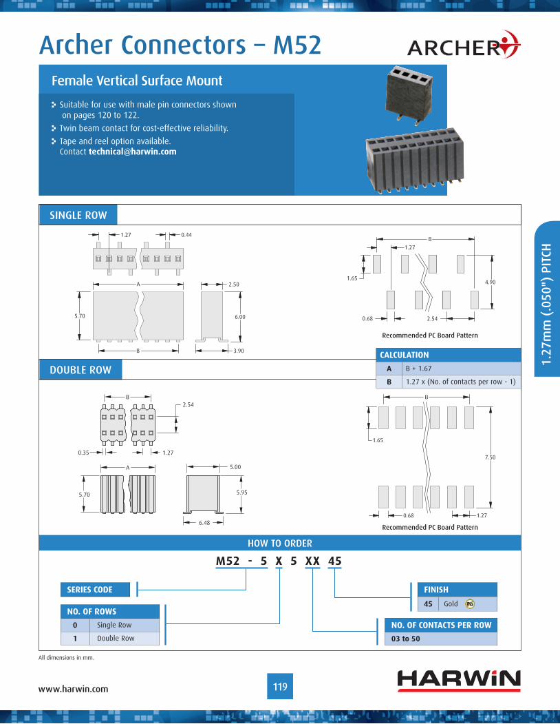
Archer Connectors – M52
A range of 1.27mm x 2.54mm male and female connectors, for vertical board-to-board applications.
Choice of connector height.
Suitable for use with male connectors shown on pages 120 to 122.
Female Vertical PC Tail
ø0.70
B
1.27
Recommended PC Board Pattern
2.50
Tail
C
0.40 square
A
1.27
B
ø0.70
B
1.27
2.54
Recommended PC Board Pattern
5.00
Tail
2.54
C
0.40 square
A
B
1.27
SINGLE ROW
DOUBLE ROW
HOW TO ORDER
CalCulation
a B + 1.67 (when C = 4.6mm)B + 1.27 (when C = 8.5mm)
B 1.27 x (No. of contacts per row - 1)
Finish
45 Gold
M52 - 5 X X XX 45
series CoDe
no. oF roWs
0 Single Row
1 Double Row
no. oF ContaCts Per roW
02 to 40heiGht
0 C = 4.6mm, Tail = 3.00mm
1 C = 8.5mm, Tail = 2.80mm
119
All dimensions in mm.
www.harwin.com
Archer Connectors – M52
1.27
mm
(.0
50")
PIT
CH
Suitable for use with male pin connectors shown on pages 120 to 122.
Twin beam contact for cost-effective reliability.
Tape and reel option available. Contact [email protected]
Female Vertical Surface Mount
SINGLE ROW
HOW TO ORDER
DOUBLE ROW
Recommended PC Board Pattern
1.27 0.44
A 2.50
6.00
3.90
5.70
B
1.27
4.90
2.540.68
1.65
B
B
1.65
7.50
1.270.68
5.00
5.70
A
5.95
6.48
0.35
B
1.27
2.54
CalCulation
a B + 1.67
B 1.27 x (No. of contacts per row - 1)
Recommended PC Board Pattern
Finish
45 Gold
series CoDe
no. oF roWs
0 Single Row
1 Double Row
M52 - 5 X 5 XX 45
no. oF ContaCts Per roW
03 to 50

All dimensions in mm.
120www.harwin.com
Male Vertical PC Tail
Suitable for use with female connectors shown on pages 118 to 119.
For alternative pin lengths, see pin header variants on page 122.
1.27mm
(.050") PITCH
Archer Connectors – M52
HOW TO ORDER
SINGLE ROW
DOUBLE ROW
Recommended PC Board Pattern
Recommended PC Board Pattern
CalCulation
a 1.27 x No. of contacts per row
B 1.27 x (No. of contacts per row - 1)
Finish
45 Gold
M52 - 040023 X XX 45
no. oF ContaCts Per roW
05, 10, 20, 25
ConneCtor tyPe
V Single Row
W Double Row
series CoDe
A
B
1.27 0.46 square
2.50
2.50
4.00
2.30
B
A
0.46 square1.27
5.00
2.54
2.50
2.30
4.00
B
1.27
Ø0.80
Ø0.80
B
1.27
2.54

121
All dimensions in mm.
www.harwin.com
Suitable for use with female connectors shown on pages 118 to 119.
For alternative pin lengths, see pin header variants on page 122.
Male Vertical Surface Mount
Archer Connectors – M52
1.27
mm
(.0
50")
PIT
CHHOW TO ORDER
SINGLE ROW DOUBLE ROW
Recommended PC Board Pattern Recommended PC Board Pattern
CalCulation
a 1.27 x No. of contacts per row
B 1.27 x (No. of contacts per row - 1)
Finish
45 Gold
M52 - 040000 X XX 45
no. oF ContaCts Per roW
05, 10, 20, 25
ConneCtor tyPe
P Single Row
s Double Row
series CoDe
A
1.27 5.00
2.50
1.27
4.00
2.50
0.46 squareB
No. 1 contact
A
B
5.00
2.54
7.20
2.50
1.27
4.00
1.27
0.46 square
B
1.272.54
0.74 3.00
6.00
B
1.27 0.74
8.60
3.75

All dimensions in mm.
122www.harwin.com
1.27mm
(.050") PITCH
Archer Connectors – M52
If you are unable to specify the connector you require from our standard range of Archer M52 connectors (pages 120 – 121), use the order code below to create an application-specific connector.
Contact [email protected] for further information, or search online for M52-XXX.
Suitable for use with female connectors on pages 118 to 119.
Pin Header Variants
HOW TO ORDER
Vertical PC Tail Extended PC Tail
Vertical SMT Extended SMT
W SeriesV Series
B dimension is 000. Pin section is 0.46mm square.
Pin section is 0.46mm square. For PCB pad layout, see page 121.For PCB pad layout, see page 121.
F SeriesE Series
S SeriesP Series T SeriesR Series
2.50
2.50
A
B
5.00
2.50
A
B
2.54
2.50 A
B
2.30
2.50
2.50
A
B
2.302.54
5.00
2.50
A
2.50
5.00 1.27
5.00
2.54
A
2.50
7.20 1.27
2.50 A
1.275.00
2.50B
5.002.54
A
1.277.20
2.50B
sinGle roW DouBle roW
V W Vertical
e F Extended
P s SMT
r t Extended SMT
Finish
45 Gold
M52 - XXX XXX X XX 45
no. oF ContaCts Per roW
02 to 50
DiMension a
Example: 7.8mm = 078
series CoDe
DiMension B
Example: 5.0mm = 050
TERMINATION STyLES
Pin section is 0.46mm square. PCB mounting hole is Ø0.80mm.
Pin section is 0.46mm square. PCB mounting hole is Ø0.80mm.