M30 Datasheet v1.0 - PowerbyProxi • Wireless Power ...€¦ · PP012-M30 V1.0 Information herein...
12
PP012-M30 V1.0 Information herein is subject to change Proxi-M30 12W Wireless Power & Data Supply PRODUCT DATASHEET 1.1 Product Marking and Labeling • Product Name: ARISO 12 Watt • Identification Number: TXM030S012PNP2A / RXM- 030S012PNP2A o Tx / Rx Transmitter / Receiver o M Form factor, M = Circular o 030 Diameter o S Product type, S = Standard o 012 Power level, 12W o PNP Data type, PnP variant o 2/8 Number of PNP channels o a/b Coding option 1. PRODUCT PART NUMBERS, MARKING AND LABELING 1.2 Part Number • 2287598-1: ARISO TXM030S012PNP2A • 2287598-3: ARISO TXM030S012PNP8A • 2287598-2: ARISO RXM030S012PNP2A • 2287598-4: ARISO RXM030S012PNP8A • 2287598-5: ARISO RXM030S012PNP8B 2. GENERAL 2.1 Design and Construction Product shall be of the design, construction and physical dimensions specified on the applicable customer product drawing (C-2287598) and product specification (108- 19484). The following variants are available. • M30, 4 pos variant, 2 PNP Channels: o ARISO TXM030S012PNP2A M30 Power Transmitter / Data Receiver. o ARISO RXM030S012PNP2A M30 Power Receiver / Data Transmitter. • M30, 12 pos variants, 8 PNP Channels: o ARISO TXM030S012PNP8A Power Transmitter / Data Receiver. o ARISO RXM030S012PNP8A Power Receiver / Data Transmitter. Optimized for connection to distribution boxes 2273161-1 (S1 only), 2273146-1, 2273139-1 and 2273134-1. o ARISO RXM030S012PNP8B Power Receiver / Data Transmitter. Optimized for connection to distribution box 2273161-1 (S2 supported at sockets 1 and 2, sockets 7 and 8 not connected). Proxi-M30 12W 2.2 Features The product has the following features: • Power input reverse polarity protection: The product switches off in case the power connected to the Tx has wrong polarity. • Power output short circuit protection/ Data output short circuit protection: The product switches off the power / data in case the outputs are short circuited or in case the load is above specification. • Data input / output reverse polarity protection: The product is protected against reversed connections of the data inputs and data outputs. • Over-temperature protection: The product switches off in case the temperature becomes too high. • Foreign Object Protection: The product switches off in case metal is put in between the power transmitter and power receiver. • Dynamic Pairing: The ARISO Couplers are interchangeable. • Status OK/ In operating range Indication: The ARISO Tx has two status signals indicating ei- ther normal operation or incorrect behavior (like over-temperature or the presence of a foreign object). © 2016 PowerbyProxi Inc. All rights reserved. Product specifications are subject to change. Contains confidential information and intellectual property of PowerbyProxi; Patents Pending. 1
Transcript of M30 Datasheet v1.0 - PowerbyProxi • Wireless Power ...€¦ · PP012-M30 V1.0 Information herein...

PP012-M30 V1.0Information herein is subject to change
Proxi-M30 12W
Wireless Power & Data SupplyPRODUCT DATASHEET
1.1 Product Marking and Labeling• Product Name: ARISO 12 Watt• Identifi cation Number: TXM030S012PNP2A / RXM-
030S012PNP2A o Tx / Rx Transmitter / Receiver o M Form factor, M = Circular o 030 Diameter o S Product type, S = Standard o 012 Power level, 12W o PNP Data type, PnP variant o 2/8 Number of PNP channels o a/b Coding option
1. PRODUCT PART NUMBERS, MARKING AND LABELING
1.2 Part Number• 2287598-1: ARISO TXM030S012PNP2A• 2287598-3: ARISO TXM030S012PNP8A• 2287598-2: ARISO RXM030S012PNP2A• 2287598-4: ARISO RXM030S012PNP8A• 2287598-5: ARISO RXM030S012PNP8B
2. GENERAL2.1 Design and Construction Product shall be of the design, construction and physical dimensions specifi ed on the applicable customer product drawing (C-2287598) and product specifi cation (108-19484).The following variants are available.• M30, 4 pos variant, 2 PNP Channels:
o ARISO TXM030S012PNP2A M30 Power Transmitter / Data Receiver. o ARISO RXM030S012PNP2A M30 Power Receiver / Data Transmitter.• M30, 12 pos variants, 8 PNP Channels:
o ARISO TXM030S012PNP8A Power Transmitter / Data Receiver. o ARISO RXM030S012PNP8A Power Receiver / Data Transmitter. Optimized for connection to distribution boxes 2273161-1 (S1 only), 2273146-1, 2273139-1 and 2273134-1. o ARISO RXM030S012PNP8B Power Receiver / Data Transmitter. Optimized for connection to distribution box 2273161-1 (S2 supported at sockets 1 and 2, sockets 7 and 8 not connected).
Proxi-M30 12W
2.2 FeaturesThe product has the following features:• Power input reverse polarity protection: The
product switches off in case the power connected to the Tx has wrong polarity.
• Power output short circuit protection/ Data output short circuit protection: The product switches off the power / data in case the outputs are short circuited or in case the load is above specifi cation.
• Data input / output reverse polarity protection: The product is protected against reversed connections of the data inputs and data outputs.
• Over-temperature protection: The product switches off in case the temperature becomes too high.
• Foreign Object Protection: The product switches off in case metal is put in between the power transmitter and power receiver.
• Dynamic Pairing: The ARISO Couplers are interchangeable.
• Status OK/ In operating range Indication: The ARISO Tx has two status signals indicating ei-ther normal operation or incorrect behavior (like over-temperature or the presence of a foreign object).
© 2016 PowerbyProxi Inc. All rights reserved. Product specifi cations are subject to change. Contains confi dential information and intellectual property of PowerbyProxi; Patents Pending. 1
PP012-M30 V1.0Information herein is subject to change
Proxi-M30 12W
Parameter Value Conditions
Diameter 30 mm M30 x 1.5,See C-2287598
Length of PTx 80 mm (excl cable) See C-2287598
Length of PRx 80 mm (excl cable) See C-2287598
Thread M30 x 1.5
Max. Tightening Torque
40 Nm
Max. Cable Pull 50 N 1 Minute
Maximum weight 150 gr150 gr
Tx, including CableRx, Including Cable
Cable length 30 cm
Housing Material Nikel Plated Brass
Front-cap Material LCP
2.3 Characteristics Overview• Rated input voltage Tx 24VDC• Rated output voltage Rx 24VDC• Power Transfer capability 12.0W @ Rx side, -20 to
+55 °C ambient temperature, maximum 7.0 mm distance between Tx and Rx
• Operating ambient temperature -20°C to 55°C• Ingress Protection IP67• Dimensions Tx M30 x 80• Dimensions Rx M30 x 80• Number of Digital GPIO Link “PNP” 2287598-1 / -2:
2 PNP Channels Digital GPIO Link, 2287598-3/ -4/ -5: 8 PNP Channels Digital GPIO Link
• Freedom of rotation no performance degradation of power and data up to 1250 rpm
2.5 Environmental DataParameter Value Conditions
Min. ambient temperature -20 °C Operational
Max. ambient temperature +55 °C Operational
OTP Threshold +65 °C
Max. ambient temperature +75 °C Powered, non-operational
Max. ambient storage temperature
+100 °C
Ingress Protection IP67 1 Minute
Mechanical shock 30g m/s2 IEC 60512-6-3
Mechanical vibration 0.01 G2/Hz IEC 60512-6-4
Free fall test 1 m IEC 60512-6-5
Rapid temperature change -20 to +80 °C
IEC 60512-11-4
Damp heat, cyclic 21 Cycles IEC 60512-11-12 low-er air 25 °C, 90-100% RH higher air 55 °C, 90-100% RH Cycle duration 12+12 hrs.
Dry heat +80 °C IEC 60512-11-9
Flowing mixed gas corrosion
IEC 60512-11-7
Electrostatic discharge 8 / 4 kV Air / ContactIEC 61000-4-2, crit. B
Radiated EM field immu-nity
10 V/m IEC 61000-4-3,80-1000 MHz
Fast transient immunity ±1 / ±2 kV Data / SupplyIEC 61000-4-4
Surge immunity ±2 kV Supply lines to ground, crit. B.
Immunity to conducted disturbances
10 Vrms IEC 61000-4-6
Power frequency magnetic field immunity
30 A/m IEC 61000-4-8, crit. A
EMC According IEC61000-6-4 EmissionAccording IEC61000-6-2ImmunityAccording CISPR-11 /EN55011, Class A
Compliance CE, UL, FCC, MIC
© 2016 PowerbyProxi Inc. All rights reserved. Product specifications are subject to change. Contains confidential information and intellectual property of PowerbyProxi; Patents Pending. 2
2.4 Mechanical DataSee customer drawings C-2287598 for full details

PP012-M30 V1.0Information herein is subject to change
Proxi-M30 12W
3. POWER LINK3.1 Power Input
Parameter Value Conditions
Input Voltage 24.0 Vdc (±10%)
Maximum standby power 1.0 W4.0 W
UnmatedMated
Maximum input current 0.75 A
Maximum inrush current 1.4 A
Reverse Polarity Protection Yes
Foreign Object Protection Yes See 3.2.7
Under-Voltage Lockout 20.3 V
UVL hysteresis 0.1 V
3.2 Power Output3.2.1 General
Parameter Value Conditions
Output Voltage 24 Vdc (±5%)
Continuous output power 12.0 W Max. 7.0 mm distance
Peak output power 12.5 W No misalignment
Max. output ripple & noise 480 mV
Operational readiness 160 ms
10 ms
Rx Power and Data ready at full load when Tx is switched on.Tx Data ready after Rx power ready. Please also take the startup time of the sensor into account
Short circuit protection Yes
Output inrush current handling capability 200 μAs 2 A during 100 μs, 10A during 20 μs
Output short circuit current 0.65 A
Over-temperature protection Yes
Maximum distance 7.0 mm See 3.2.3
Maximum misalignment 5.0 mm At 4 mm, see 3.2.2
Maximum tilt 30° At 7 mm, See 3.2.2
Rotational invariance 1250* RPM See 3.2.6*
Minimum inter coupler distance 60 mm See 3.2.5
Minimum metal clearance in x-y direction 15 mm See 3.2.8
Minimum metal clearance in z direction 10 mm See 3.2.8
* Tested at another version
© 2016 PowerbyProxi Inc. All rights reserved. Product specifications are subject to change. Contains confidential information and intellectual property of PowerbyProxi; Patents Pending. 3
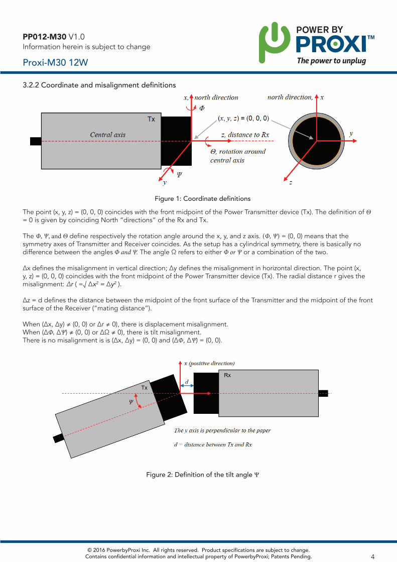
3.2.2 Coordinate and misalignment definitions
PP012-M30 V1.0Information herein is subject to change
Proxi-M30 12W
Figure 1: Coordinate definitionsThe point (x, y, z) = (0, 0, 0) coincides with the front midpoint of the Power Transmitter device (Tx). The definition of Θ = 0 is given by coinciding North “directions” of the Rx and Tx.
The Φ, Ψ, and Θ define respectively the rotation angle around the x, y, and z axis. (Φ, Ψ) = (0, 0) means that the symmetry axes of Transmitter and Receiver coincides. As the setup has a cylindrical symmetry, there is basically no difference between the angles Φ and Ψ. The angle Ω refers to either Φ or Ψ or a combination of the two.
Δx defines the misalignment in vertical direction; Δy defines the misalignment in horizontal direction. The point (x, y, z) = (0, 0, 0) coincides with the front midpoint of the Power Transmitter device (Tx). The radial distance r gives the misalignment: Δr ( =√ Δx2 = Δy2 ).
Δz = d defines the distance between the midpoint of the front surface of the Transmitter and the midpoint of the front surface of the Receiver (“mating distance”).
When (Δx, Δy) ≠ (0, 0) or Δr ≠ 0), there is displacement misalignment. When (ΔΦ, ΔΨ) ≠ (0, 0) or ΔΩ ≠ 0), there is tilt misalignment. There is no misalignment is is (Δx, Δy) = (0, 0) and (ΔΦ, ΔΨ) = (0, 0).
Figure 2: Definition of the tilt angle Ψ
© 2016 PowerbyProxi Inc. All rights reserved. Product specifications are subject to change. Contains confidential information and intellectual property of PowerbyProxi; Patents Pending. 4
PP012-M30 V1.0Information herein is subject to change
Proxi-M30 12W
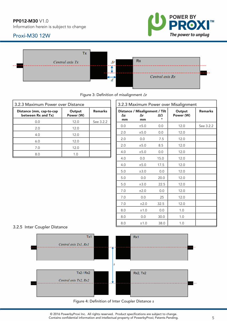
Figure 3: Definition of misalignment Δr
3.2.3 Maximum Power over DistanceDistance (mm, cap-to-cap
between Rx and Tx)Output
Power (W)Remarks
0.0 12.0 See 3.2.2
2.0 12.0
4.0 12.0
6.0 12.0
7.0 12.0
8.0 1.0
3.2.3 Maximum Power over MisalignmentDistance / Misalignment / Tilt
Δz Δr ΔΩmm mm °
Output Power (W)
Remarks
0.0 ±5.0 0.0 12.0 See 3.2.2
2.0 ±5.0 0.0 12.0
2.0 0.0 7.5 12.0
2.0 ±5.0 8.5 12.0
4.0 ±5.0 0.0 12.0
4.0 0.0 15.0 12.0
4.0 ±5.0 17.5 12.0
5.0 ±3.0 0.0 12.0
5.0 0.0 20.0 12.0
5.0 ±3.0 22.5 12.0
7.0 ±2.0 0.0 12.0
7.0 0.0 25 12.0
7.0 ±2.0 32.5 12.0
8.0 ±1.0 0.0 1.0
8.0 0.0 30.0 1.0
8.0 ±1.0 38.0 1.03.2.5 Inter Coupler Distance
© 2016 PowerbyProxi Inc. All rights reserved. Product specifications are subject to change. Contains confidential information and intellectual property of PowerbyProxi; Patents Pending. 5
Figure 4: Definition of Inter Coupler Distance s
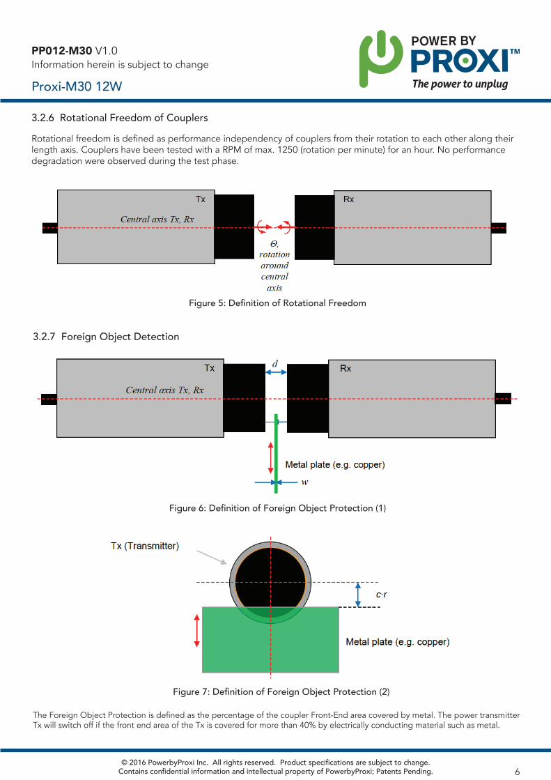
Figure 5: Definition of Rotational Freedom
3.2.6 Rotational Freedom of Couplers
PP012-M30 V1.0Information herein is subject to change
Proxi-M30 12W
Rotational freedom is defined as performance independency of couplers from their rotation to each other along their length axis. Couplers have been tested with a RPM of max. 1250 (rotation per minute) for an hour. No performance degradation were observed during the test phase.
Figure 6: Definition of Foreign Object Protection (1)
3.2.7 Foreign Object Detection
Figure 7: Definition of Foreign Object Protection (2)
The Foreign Object Protection is defined as the percentage of the coupler Front-End area covered by metal. The power transmitter Tx will switch off if the front end area of the Tx is covered for more than 40% by electrically conducting material such as metal.
© 2016 PowerbyProxi Inc. All rights reserved. Product specifications are subject to change. Contains confidential information and intellectual property of PowerbyProxi; Patents Pending. 6

PP012-M30 V1.0Information herein is subject to change
Proxi-M30 12W
3.2.8 Metal Clearance
Figure 8: Definition of Metal ClearanceThe metal clearance is the shortest distance between any part of the metal housing / plastic front-end and surround-ing metal. Note that there is a difference between the metal clearance in the x-y direction and the metal clearance in the z direction.
4. DATA LINK
4.1. GPI, General Purpose Digital Inputs (PNP) at Rx sideParameter Value Conditions
Maximum Input Voltage 36 V
Minimum Input Voltage -1 V
Minimum Input High Level 8 V
Maximum Input Low Level 5 V
Input Load current < 4.5 mA
Maximum switching frequency
500 Hz Single channel
4.2. GPO, General Purpose Digital Output (PNP) at Rx sideParameter Value Conditions
Number of Channels 8
Maximum Output Voltage 24 V Equal to input voltage
Minimum Output Voltage 0 V
Output Stage Type PNP
Max. Impedance High 4 Ω
Min. Impedance Low 1M Ω Single channel
Maximum Output Current 250 mA (+/- 20%)
Overcurrent protected, see note
Maximum Delay + Jitter 400 μs Single channel, see figure 9
Figure 9: Definition of Delay and Jitter for GPIO digital outputs
Note: All digital outputs are over-current protected, the total sum of all currents from GPIO-1 to GPIO-8, FOD and Status NOK cannot be larger than specified.
© 2016 PowerbyProxi Inc. All rights reserved. Product specifications are subject to change. Contains confidential information and intellectual property of PowerbyProxi; Patents Pending. 7

PP012-M30 V1.0Information herein is subject to change
Proxi-M30 12W
5. IN OPERATING RANGE / STATUS INDICATIONThe ARISO Transmitter (Tx) has two status signals indication the status of operation. These two signals, Status_NOK and FOD, indicate following states:
State Description FOD Level Status_NOK Level Notes
Tx powered, Rx unit missing Low High
Tx powered, Rx paired with Tx Low Low System in operating range & normal operation
Tx powered, Rx paired with Tx, System error
Low High System error e.g.: Over temperatureRx obstructed by Foreign Object
Tx powered, Rx paired with Tx, Too high power by FOD
High High System error e.g.: Rx obstructed by Foreign Object
6. CONNECTOR PINNING CODINGThe Transmitter (Tx) and Receiver (Rx) are equipped with a cable attached to a standard 4 or 12-pos M12 connector. For the pin definitions see figure 10 and 11. For the mechanical outline see customer drawing C-2287598.
6.1 Connector Pin Definitions
Figure 11: Pinning of 12 pins connectors (mating face view)
© 2016 PowerbyProxi Inc. All rights reserved. Product specifications are subject to change. Contains confidential information and intellectual property of PowerbyProxi; Patents Pending. 8
PP012-M30 V1.0Information herein is subject to change
Proxi-M30 12W
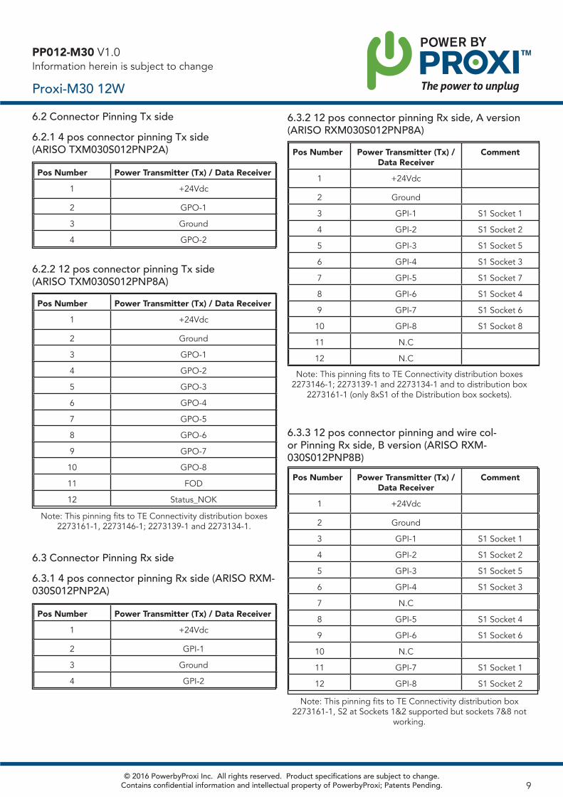
6.2 Connector Pinning Tx side6.2.1 4 pos connector pinning Tx side (ARISO TXM030S012PNP2A)
Pos Number Power Transmitter (Tx) / Data Receiver
1 +24Vdc
2 GPO-1
3 Ground
4 GPO-2
Pos Number Power Transmitter (Tx) / Data Receiver
1 +24Vdc
2 Ground
3 GPO-1
4 GPO-2
5 GPO-3
6 GPO-4
7 GPO-5
8 GPO-6
9 GPO-7
10 GPO-8
11 FOD
12 Status_NOK
6.2.2 12 pos connector pinning Tx side (ARISO TXM030S012PNP8A)
Note: This pinning fits to TE Connectivity distribution boxes 2273161-1, 2273146-1; 2273139-1 and 2273134-1.
6.3 Connector Pinning Rx side6.3.1 4 pos connector pinning Rx side (ARISO RXM-030S012PNP2A)
Pos Number Power Transmitter (Tx) / Data Receiver
1 +24Vdc
2 GPI-1
3 Ground
4 GPI-2
Pos Number Power Transmitter (Tx) / Data Receiver
Comment
1 +24Vdc
2 Ground
3 GPI-1 S1 Socket 1
4 GPI-2 S1 Socket 2
5 GPI-3 S1 Socket 5
6 GPI-4 S1 Socket 3
7 GPI-5 S1 Socket 7
8 GPI-6 S1 Socket 4
9 GPI-7 S1 Socket 6
10 GPI-8 S1 Socket 8
11 N.C
12 N.C
6.3.2 12 pos connector pinning Rx side, A version (ARISO RXM030S012PNP8A)
Note: This pinning fits to TE Connectivity distribution boxes 2273146-1; 2273139-1 and 2273134-1 and to distribution box
2273161-1 (only 8xS1 of the Distribution box sockets).
Pos Number Power Transmitter (Tx) / Data Receiver
Comment
1 +24Vdc
2 Ground
3 GPI-1 S1 Socket 1
4 GPI-2 S1 Socket 2
5 GPI-3 S1 Socket 5
6 GPI-4 S1 Socket 3
7 N.C
8 GPI-5 S1 Socket 4
9 GPI-6 S1 Socket 6
10 N.C
11 GPI-7 S1 Socket 1
12 GPI-8 S1 Socket 2
6.3.3 12 pos connector pinning and wire col-or Pinning Rx side, B version (ARISO RXM-030S012PNP8B)
Note: This pinning fits to TE Connectivity distribution box 2273161-1, S2 at Sockets 1&2 supported but sockets 7&8 not
working.
© 2016 PowerbyProxi Inc. All rights reserved. Product specifications are subject to change. Contains confidential information and intellectual property of PowerbyProxi; Patents Pending. 9
PP012-M30 V1.0Information herein is subject to change
Proxi-M30 12W
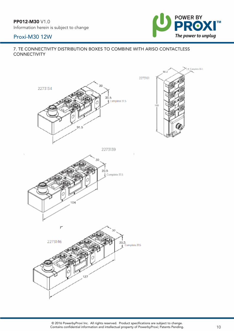
7. TE CONNECTIVITY DISTRIBUTION BOXES TO COMBINE WITH ARISO CONTACTLESSCONNECTIVITY
© 2016 PowerbyProxi Inc. All rights reserved. Product specifications are subject to change. Contains confidential information and intellectual property of PowerbyProxi; Patents Pending. 10
8. DATA LINKNote that the digital output (GPO) does not have a reverse polarity protection. Extra care should be taken to assure that the output is con-nected correctly.
9. UNSPECIFIED SITUATIONSThere are a number of unspecified situations in which the operation is not guaranteed. Despite the fact that the operation is not guaranteed there will be no damage to the product.
9.1 Mating distance larger than 7 mm
In case the distance is just over 7 mm (at full load) or over 8 mm (at low load) the voltage output of the Rx might be unstable in the sense that is keeps on switching on and off.
9.2 Input voltage below 24V – 10%
Although an Under-Voltage Lockout is specified (20V ± 5%) the be-haviour at voltage levels between the Under-Voltage Lockout level and the minimum input voltage (21.6V) is not defined. Repeating on- and off-switching of the output voltage at the Rx side might occur depend-ing upon the load and the actual input voltage.
9.3 Metal clearance less than 30 mm
Although Foreign Object Detection is implemented no metal objects should be placed in the region between the Transmitter and Receiver. Those metal objects might get hot depending upon their geometry.
9.4 Inter coupler distance less than 60 mm
In case two coupler pairs are located in close proximity (distance be-tween central axes of both pairs less than 60 mm) both power transfer and data transfer of the two pairs might be affected by the proximity of the other coupler pair.
9.5 Ambient temperature higher than 60°C
Although the power transmitter side has an OTP, putting the Rx side in an environment higher than 60°C might result in malfunctioning.
9.6 UV environment
The product should not be used in environments with high UV radiation or with chemical compounds.
10. SAFETY NOTES AND DISCLAIMERS10.1 Personnel requirementsInstallation and startup are permitted only by trained technicians.
10.2 Non-intended useGuarantee and warranty claims against the manufacturer are rendered non-redeemable by unauthorized operations, tampering and non-intended use.
10.3 Electric and magnetic field emissionThe device (coupler pair) can be used according to its intended applica-tion (keeping minimum separation distance of 20 cm from human body) without any access restrictions.
10.4 Hot surfaces
The active surface heats up even under normal operation condi-tions. Contact of metal objects on the active surface should be avoided (Fire hazard).
10.5 Foreign metal objects
Although Foreign Object Detection is implemented, small metal devices located between the transmitter and receiver can get very hot, even with the risk of fire in case of combustible material in close proxim-ity of the metal. Whether the metal devices will get hot depends upon their size and geometry.
10.6 Power supplyThe power supply generating the necessary 24V for the power transmit-ter should have either double isolated or re-enforced isolation (safety extra LV output: double reinforced isolation from primary mains). Out-puts should be Class II protected.
10.7 Cable protectionEspecially in moving and/or rotating applications the cables should be protected and mounted into clips / straps. In static application the cable bending radius at coupler shall be at minimum 5x cable diameter. In dynamic application the cable bending radius shall be at minimum 10x cable diameter.
10.8 Moving and rotating applications
Especially in moving and/or rotating applications the cables should be protected and mounted into clips / straps. In dynamic application the cable bending radius shall be at minimum 10x cable di-ameter. Furthermore, especially in rotating applications special attention should be paid to the balance of the total setup.
10.9 Human protection
Especially in moving / rotation applications the human body should be protected against any harm (crushing, cutting etc.). See also 10.3, “electric and magnetic field emission”.
10.10 Safety and environment
This product shall not be used in a safety critical application.
PP012-M30 V1.0Information herein is subject to change
Proxi-M30 12W
© 2016 PowerbyProxi Inc. All rights reserved. Product specifications are subject to change. Contains confidential information and intellectual property of PowerbyProxi; Patents Pending. 11

© 2016 PowerbyProxi Inc. All rights reserved. Product specifications are subject to change. Contains confidential information and intellectual property of PowerbyProxi; Patents Pending.
New Zealand: 5 Wilkins street, Freemans Bay Auckland, 1011Phone: +64 (9) 914 8311
Enquiries: [email protected] Sales: +1 (512) 827 3571Web: www.powerbyproxi.com
12
Texas: 12612 Capella Trail Austin, TX 78732 Phone: +1 (512) 827 3571 Fax: +1 (512) 582 8543
PP012-M30 V1.0Information herein is subject to change
Proxi-M30 12WNOTES AND STATEMENTS:Intended use: Coupler to transfer 12W power and data (digital GPIO link), integrated in a control system.
This device complies with Industry Canada licence-exempt RSS standard(s) and part 15 of the FCC Rules. Operation is subject to the following two conditions: (1) this device may not cause interference, and (2) this device must accept any interference, including interference that may cause undesired operation of the device.
Changes or modifications not expressly approved by the party responsible for compliance could void the user's authority to operate the equipment.
This equipment has been tested and found to comply with the limits for a Class A digital device, pursuant to part 15 of the FCC Rules. These limits are designed to provide reasonable protection against harmful interference when the equipment is operated in a commercial environment. This equipment generates, uses, and can radiate radio frequency energy and, if not installed and used in accordance with the instruction manual, may cause harmful interference to radio communications. Operation of this equipment in a residential area is likely to cause harmful interference in which case the user will be required to correct the interference at his own expense.
The interference potential of the device is low as it is a low frequency device with a near field antenna, designed to provide rea-sonable protection against harmful interference when the equipment is operated in a commercial environment and accordingly tested.
If this equipment does cause harmful interference, which can be determined by turning the equipment off and on by disconnect-ing the couplers from the power und signal source, the user is encouraged to try to correct the interference by one or more of the following measures:
• Increase the separation between this equipment and the disturbed one• Consult the dealer or an experienced technician for help
No maintenance of the device is needed, once installed and used in accordance with the instruction manual.
Notes et declarations:
Le présent appareil est conforme aux CNR d'Industrie Canada applicables aux appareils radio exempts de licence. L'exploitation est autorisée aux deux condition suivantes: (1) l'appareil ne doit pas produire de brouillage, et (2) l'appareil doit accepter tout brouillage radioélectrique subi, même si le brouillage est susceptible d'en compromettre le fonctionnement.
Nummer der „Benannten Stelle“ (NBnr): 0344