M20 Advanced Drawing Production
180
Version 11.5 Module 20 Advanced Drawing Production Training Manual
description
PDMS
Transcript of M20 Advanced Drawing Production
Version 11.5
Module 20
Advanced Drawing Production
Training Manual
Cadcentre Ltd, High Cross, Madingley Road, Cambridge CB3 0HB, UK
PLEASE NOTE:
Cadcentre has a policy of continuing product development: therefore, the information contained in this document may be subject to change without notice.
CADCENTRE MAKES NO WARRANTY OF ANY KIND WITH REGARD TO THIS DOCUMENT, INCLUDING BUT NOT LIMITED TO, THE IMPLIED WARRANTIES OF MERCHANTABILITY AND FITNESS FOR A PARTICULAR PURPOSE.
While every effort has been made to verify the accuracy of this document, Cadcentre shall not be liable for errors contained herein or direct, indirect, special, incidental or consequential damages in connection with the furnishing, performance or use of this material.
This manual provides documentation relating to products that you may not have access to or which may not be licensed to you. For further information on which products are licensed to you please refer to your licence conditions.
Copyright 2004 Cadcentre Limited
All rights reserved. No part of this document may be reproduced, stored in a retrieval system or transmitted, in any form or by any means, electronic, mechanical, photocopying, recording or otherwise, without prior written permission of Cadcentre. The software programs described in this document are confidential information and proprietary products of Cadcentre Ltd or its licensors.
Visit our website at http://www.cadcentre.com
Contents
Module 20 Advanced Drawing Production contents-i
Contents
Session 1 .....................................................................1-1 The DRAFT Hierarchy ................................ ............................................................1-1 Objectives.................................................................................................................1-1 Must Know Points.....................................................................................................1-1 Departments .............................................................................................................1-2 Registries..................................................................................................................1-3 Drawings...................................................................................................................1-4 Creating Explicitly .....................................................................................................1-5 Creating From a Template........................................................................................1-5 Libraries (under user control) ...................................................................................1-6 Modification ..............................................................................................................1-6 Name… ....................................................................................................................1-7 Department… ...........................................................................................................1-7 Registry….................................................................................................................1-7 Drawing ....................................................................................................................1-7 Definition…...............................................................................................................1-7 Attributes…...............................................................................................................1-7 Drawlist Ref…...........................................................................................................1-8
Session 2 .....................................................................2-1 Sheet and View Creation .............................. .........................................................2-1 Objectives.................................................................................................................2-1 Must Know Points.....................................................................................................2-1 Create a SHEET.......................................................................................................2-1 Explicitly....................................................................................................................2-2 From Template .........................................................................................................2-3 Creating View Elements ...........................................................................................2-4 CREATE VIEW.........................................................................................................2-4 Creating a Limits-defined VIEW ...............................................................................2-5 Drawing the Picture and VIEW Manipulation ...........................................................2-8 Control of the View Frame........................................................................................2-9 Setting of Limits ........................................................................................................2-9 Centre of Interest of the View...................................................................................2-9 Setting the Views Contents ....................................................................................2-10 Changes to the View Settings ................................................................................2-13 Creating a User–Defined VIEW..............................................................................2-13 Creating a set of Predefined–Frame VIEWs ..........................................................2-22 Creation Of Drawlists..............................................................................................2-24 Modification ............................................................................................................2-24 Exercises ................................................................................................................2-25
Contents
Contents-ii Module 20 Advanced Drawing Production
Session 3 .....................................................................3-1 Dimensioning ....................................... .................................................................. 3-1 Moving Dimension Text.......................................................................................... 3-12 Gap Creation.......................................................................................................... 3-13
Session 4 .....................................................................4-1 Labelling .......................................... ....................................................................... 4-1 Using Symbols in DRAFT ........................................................................................ 4-3 Creating Labels ........................................................................................................ 4-4 Moving A Symbolic Label Select Position>Label followed by Default, Cursor or Att.Point as required from the Symbolic Labels form............................................... 4-8 Gaps in Leader Lines ............................................................................................... 4-9 Creating a General Label ....................................................................................... 4-10 Label Contents Form.............................................................................................. 4-11 Moving a Label....................................................................................................... 4-12 Bending the Leader Line ........................................................................................ 4-12 Creating a Pipe End Symbol .................................................................................. 4-13 Modifying Elements................................................................................................ 4-14 Label Geometry...................................................................................................... 4-15 Label Blanking........................................................................................................ 4-16 Label Placement .................................................................................................... 4-17 Exercises................................................................................................................ 4-20
Session 5 .....................................................................5-1 Autotagging .......................................... .................................................................. 5-1 Autotagging .............................................................................................................. 5-1 Creating Tags........................................................................................................... 5-2 Defining Library Styles ............................................................................................. 5-3 Defining Local Tagging ............................................................................................ 5-3 Change Autotagging Template Library .................................................................... 5-5 Exercise ................................................................................................................... 5-7
Session 6 .....................................................................6-1 Section Planes...................................... .................................................................. 6-1 Modifying Section Planes......................................................................................... 6-7 Exercise ................................................................................................................. 6-11
Session 7 .....................................................................7-1 The 2D Drafting Application........................... ....................................................... 7-1 The 2D Drafting Hierarchy ....................................................................................... 7-3 Creating 2D Drafting Base Elements ....................................................................... 7-3
Contents
Module 20 Advanced Drawing Production contents-iii
Creation of Notes......................................................................................................7-4 Modifying 2D Drafting Base Elements......................................................................7-6 Deleting Elements ....................................................................................................7-6 2D Drafting Primitives...............................................................................................7-6 Creating 2D Primitives..............................................................................................7-7 Constructed Points ...................................................................................................7-7 Creating 2D Primitives from Icon Selection..............................................................7-8 Miscellaneous Construction Options ......................................................................7-15 2D Settings .............................................................................................................7-20 2D Utilities ..............................................................................................................7-21 Exercise..................................................................................................................7-24
Session 8 .....................................................................8-1 Automatic Drawing Production (ADP)..................... .............................................8-1 Changing Application ...............................................................................................8-1 ADP Hierarchy..........................................................................................................8-2 Creating an ADP Drawing ........................................................................................8-3 Creating ADP Sheet .................................................................................................8-5 ADP View Creation.................................................................................................8-10 General Settings.....................................................................................................8-11 Limits ......................................................................................................................8-12 Exercise..................................................................................................................8-19
Session 9 .....................................................................9-1 Settings ............................................. ......................................................................9-1 Global Settings .........................................................................................................9-2 Global Settings Form................................................................................................9-2 User Defaults............................................................................................................9-3 Point Construction ....................................................................................................9-4 Utilities ......................................................................................................................9-6 Clash Plotting ...........................................................................................................9-9 Reports ...................................................................................................................9-13 General Toolbar......................................................................................................9-13 DB Listing ...............................................................................................................9-14 DB Listing form.......................................................................................................9-15 Claimlist ..................................................................................................................9-15 Claims List form......................................................................................................9-15
Appendix A .................................................................. A-1 View Types ......................................... ........................................................... A-1
Appendix B .................................................................. B-1 DRAFT Database Hierarchy ............................ ............................................. B-1
Contents
Contents-iv Module 20 Advanced Drawing Production
Appendix C ..................................................................C-1 Dimension Example Sheets ............................ .............................................C-1
Appendix D ..................................................................D-1 Label Example Sheets ................................ ..................................................D-1
Appendix E................................................................... E-1 Section Example Sheets............................... ................................................E-1
Appendix F ................................................................... F-1 2D Drafting Example Sheets ............................ ............................................F-1
Module 20 Advanced Drawing Production 1-1
The DRAFT Hierarchy
Objectives
At the end of this session, you will able to:
• •
•
Must Know Points
The following points need to be understood by the trainees.
•
•
Błąd! Nie zdefiniowano stylu.
1-2 Module 20 Advanced Drawing Production
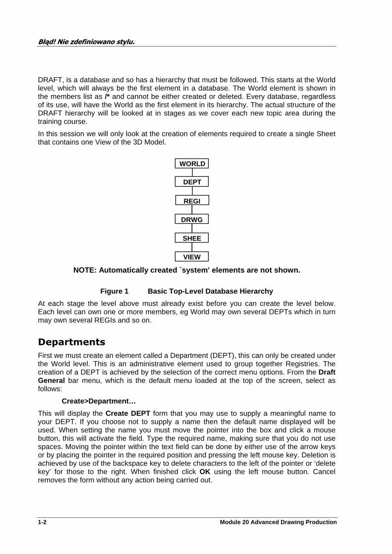
DRAFT, is a database and so has a hierarchy that must be followed. This starts at the World level, which will always be the first element in a database. The World element is shown in the members list as /* and cannot be either created or deleted. Every database, regardless of its use, will have the World as the first element in its hierarchy. The actual structure of the DRAFT hierarchy will be looked at in stages as we cover each new topic area during the training course.
In this session we will only look at the creation of elements required to create a single Sheet that contains one View of the 3D Model.
NOTE: Automatically created `system' elements are n ot shown.
WORLD
DEPT
REGI
DRWG
SHEE
VIEW
Figure 1 Basic Top-Level Database Hierarchy
At each stage the level above must already exist before you can create the level below. Each level can own one or more members, eg World may own several DEPTs which in turn may own several REGIs and so on.
Departments
First we must create an element called a Department (DEPT), this can only be created under the World level. This is an administrative element used to group together Registries. The creation of a DEPT is achieved by the selection of the correct menu options. From the Draft General bar menu, which is the default menu loaded at the top of the screen, select as follows:
Create>Department…
This will display the Create DEPT form that you may use to supply a meaningful name to your DEPT. If you choose not to supply a name then the default name displayed will be used. When setting the name you must move the pointer into the box and click a mouse button, this will activate the field. Type the required name, making sure that you do not use spaces. Moving the pointer within the text field can be done by either use of the arrow keys or by placing the pointer in the required position and pressing the left mouse key. Deletion is achieved by use of the backspace key to delete characters to the left of the pointer or ‘delete key’ for those to the right. When finished click OK using the left mouse button. Cancel removes the form without any action being carried out.
Błąd! Nie zdefiniowano stylu.
Module 20 Advanced Drawing Production 1-3
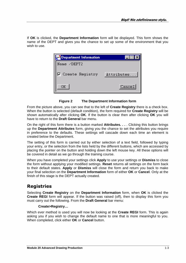
If OK is clicked, the Department Information form will be displayed. This form shows the name of the DEPT and gives you the chance to set up some of the environment that you wish to use.
Figure 2 The Department Information form From the picture above, you can see that to the left of Create Registry there is a check box. When the button is selected (default condition), the form required for Create Registry will be shown automatically after clicking OK. If the button is clear then after clicking OK you will have to return to the Draft General bar menu.
On the right of this form there is a button marked Attributes. . . . Clicking this button brings up the Department Attributes form, giving you the chance to set the attributes you require in preference to the defaults. These settings will cascade down each time an element is created below the Department.
The setting of this form is carried out by either selection of a text field, followed by typing your entry, or the selection from the lists held by the different buttons, which are accessed by placing the pointer on the button and holding down the left mouse key. All these options will be covered in detail as we go through the training course.
When you have completed your settings click Apply to use your settings or Dismiss to close the form without applying your modified settings. Reset returns all settings on the form back to their default states. Apply or Dismiss will close the form and return you back to make your final selection on the Department Information form of either OK or Cancel . Only at the finish of this stage is the DEPT actually created.
Registries
Selecting Create Registry on the Department Information form, when OK is clicked the Create REGI form will appear. If the button was raised (off), then to display this form you must carry out the following. From the Draft General bar menu:
Create>Registry…
Which ever method is used you will now be looking at the Create REGI form. This is again asking you if you wish to change the default name to one that is more meaningful to you. When completed, click either OK or Cancel button.
Błąd! Nie zdefiniowano stylu.
1-4 Module 20 Advanced Drawing Production
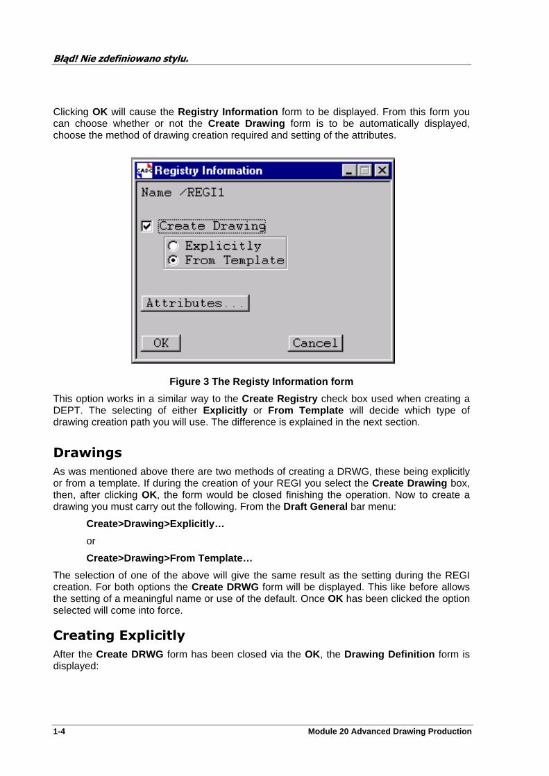
Clicking OK will cause the Registry Information form to be displayed. From this form you can choose whether or not the Create Drawing form is to be automatically displayed, choose the method of drawing creation required and setting of the attributes.
Figure 3 The Registy Information form
This option works in a similar way to the Create Registry check box used when creating a DEPT. The selecting of either Explicitly or From Template will decide which type of drawing creation path you will use. The difference is explained in the next section.
Drawings
As was mentioned above there are two methods of creating a DRWG, these being explicitly or from a template. If during the creation of your REGI you select the Create Drawing box, then, after clicking OK, the form would be closed finishing the operation. Now to create a drawing you must carry out the following. From the Draft General bar menu:
Create>Drawing>Explicitly…
or
Create>Drawing>From Template…
The selection of one of the above will give the same result as the setting during the REGI creation. For both options the Create DRWG form will be displayed. This like before allows the setting of a meaningful name or use of the default. Once OK has been clicked the option selected will come into force.
Creating Explicitly
After the Create DRWG form has been closed via the OK, the Drawing Definition form is displayed:
Błąd! Nie zdefiniowano stylu.
Module 20 Advanced Drawing Production 1-5
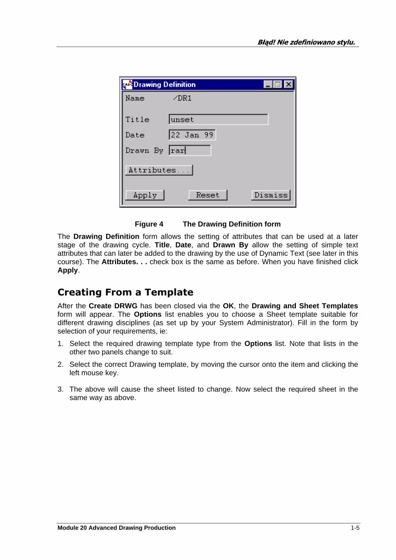
Figure 4 The Drawing Definition form
The Drawing Definition form allows the setting of attributes that can be used at a later stage of the drawing cycle. Title , Date, and Drawn By allow the setting of simple text attributes that can later be added to the drawing by the use of Dynamic Text (see later in this course). The Attributes. . . check box is the same as before. When you have finished click Apply .
Creating From a Template
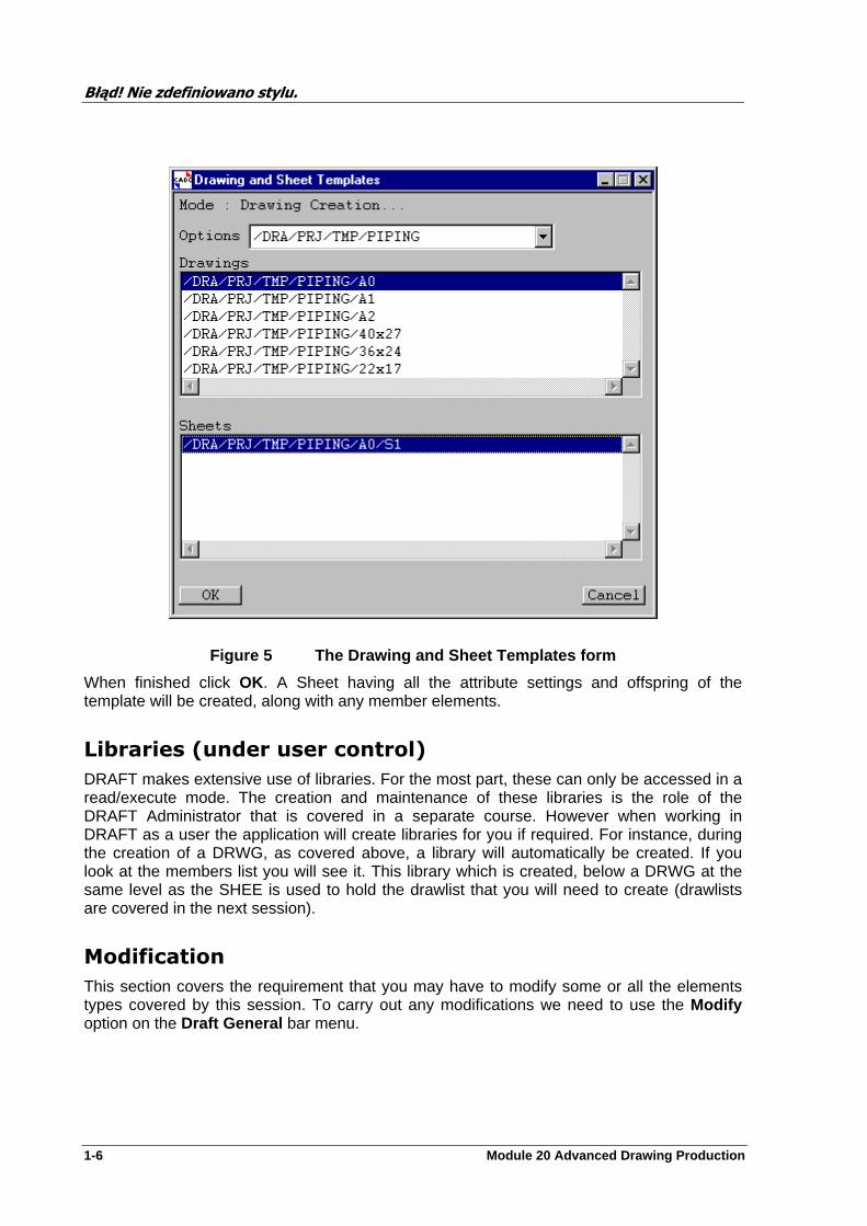
After the Create DRWG has been closed via the OK, the Drawing and Sheet Templates form will appear. The Options list enables you to choose a Sheet template suitable for different drawing disciplines (as set up by your System Administrator). Fill in the form by selection of your requirements, ie:
1. Select the required drawing template type from the Options list. Note that lists in the other two panels change to suit.
2. Select the correct Drawing template, by moving the cursor onto the item and clicking the left mouse key.
3. The above will cause the sheet listed to change. Now select the required sheet in the same way as above.
Błąd! Nie zdefiniowano stylu.
1-6 Module 20 Advanced Drawing Production
Figure 5 The Drawing and Sheet Templates form
When finished click OK. A Sheet having all the attribute settings and offspring of the template will be created, along with any member elements.
Libraries (under user control)
DRAFT makes extensive use of libraries. For the most part, these can only be accessed in a read/execute mode. The creation and maintenance of these libraries is the role of the DRAFT Administrator that is covered in a separate course. However when working in DRAFT as a user the application will create libraries for you if required. For instance, during the creation of a DRWG, as covered above, a library will automatically be created. If you look at the members list you will see it. This library which is created, below a DRWG at the same level as the SHEE is used to hold the drawlist that you will need to create (drawlists are covered in the next session).
Modification
This section covers the requirement that you may have to modify some or all the elements types covered by this session. To carry out any modifications we need to use the Modify option on the Draft General bar menu.
Błąd! Nie zdefiniowano stylu.
Module 20 Advanced Drawing Production 1-7
Name…
This allows you to rename all elements held within the DRAFT database. When selected the Element Naming form is displayed with the name of the current element displayed in the Name text field. To alter the name, simply move the cursor into the text field and click the left mouse key, thereby selecting it. You may now delete, or add characters as required. When finished press the Enter key. By default the list option below the text field is Only . If you change this to Re-name all , then depending on your position in the hierarchy, all elements will be renamed. If you choose the Un-name option this will return the element to its default name.
The CE (current element) button is used when there is another element that needs to be renamed. By selecting the other element in the Members list and clicking CE the form will be updated to show the name of that element.
Department…
This calls the Department Attributes form, which will display all the settings that were applied to the Department when it was created, if any. Edit this form as required and Apply .
Registry…
This simply calls the Registry Attributes form, which will display all the settings that were applied to the Registry when it was created, if any. Edit this form as required and Apply .
Drawing
This has three options on the sub-menu. These are:
Definition… Attributes… Drawlist Ref…
Definition…
This recalls the Drawing Definition form to the screen that you can edit etc. as required. Press Apply to use the new settings.
Attributes…
This calls the Drawing Attributes form, which will display all the settings that were applied to the Drawing when it was created, if any. Edit this form as required and Apply .
Drawlist Ref…
This allows the resetting of the Drawlist to be used. The creation of these is covered in the next session.

Module 20 Advanced Drawing Production 2-1
Sheet and View Creation
Objectives
At the end of this session, you will able to:
•
•
•
Must Know Points
The following points need to be understood by the trainees.
•
•
Create a SHEET
A Sheet (with member elements) may be created automatically when a Drawing is created using the Create > Drawing >From Template . . . menu option. Sheets may also be created ‘manually’ using one of the following menu selections, from the DRAFT General menu when positioned at the DRWG level or lower.
Create > Sheet > Explicitly . . . or Create > Sheet > From Template . . .
Explicitly
On selection the Create SHEE form will appear. A default sheet name will be automatically assigned, which you can change if you wish. On completion Click on OK or Cancel.
Błąd! Nie zdefiniowano stylu.
2-2 Module 20 Advanced Drawing Production
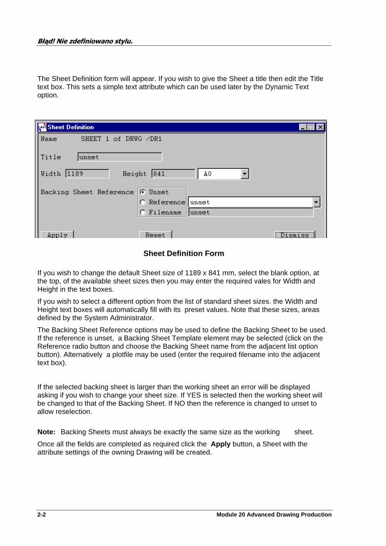
The Sheet Definition form will appear. If you wish to give the Sheet a title then edit the Title text box. This sets a simple text attribute which can be used later by the Dynamic Text option.
Sheet Definition Form
If you wish to change the default Sheet size of 1189 x 841 mm, select the blank option, at the top, of the available sheet sizes then you may enter the required vales for Width and Height in the text boxes.
If you wish to select a different option from the list of standard sheet sizes. the Width and Height text boxes will automatically fill with its preset values. Note that these sizes, areas defined by the System Administrator.
The Backing Sheet Reference options may be used to define the Backing Sheet to be used. If the reference is unset, a Backing Sheet Template element may be selected (click on the Reference radio button and choose the Backing Sheet name from the adjacent list option button). Alternatively a plotfile may be used (enter the required filename into the adjacent text box).
If the selected backing sheet is larger than the working sheet an error will be displayed asking if you wish to change your sheet size. If YES is selected then the working sheet will be changed to that of the Backing Sheet. If NO then the reference is changed to unset to allow reselection.
Note: Backing Sheets must always be exactly the same size as the working sheet.
Once all the fields are completed as required click the Apply button, a Sheet with the attribute settings of the owning Drawing will be created.
Błąd! Nie zdefiniowano stylu.
Module 20 Advanced Drawing Production 2-3
From Template
On selection the Create SHEE form will appear. A default sheet name will be automatically assigned, which you can change if you wish. On completion Click on OK or Cancel .
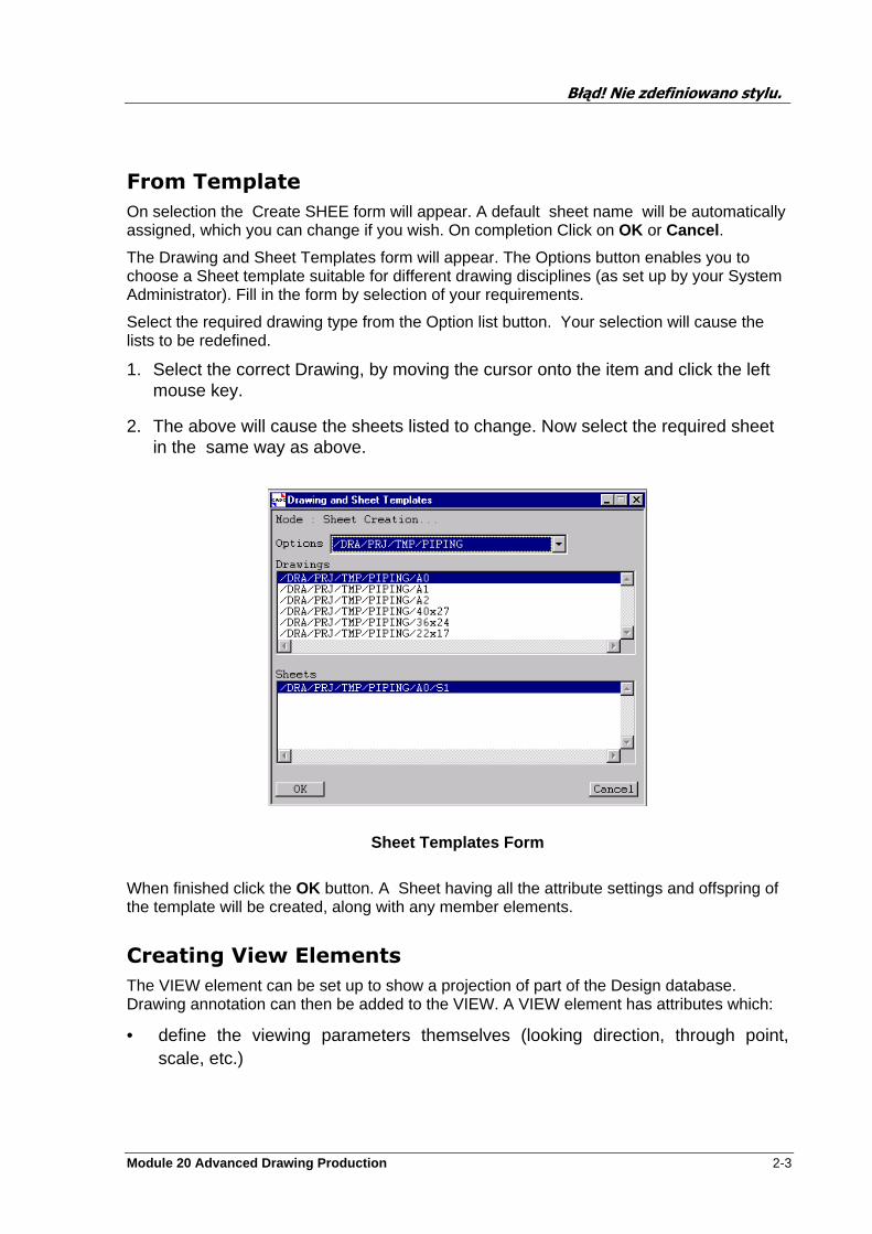
The Drawing and Sheet Templates form will appear. The Options button enables you to choose a Sheet template suitable for different drawing disciplines (as set up by your System Administrator). Fill in the form by selection of your requirements.
Select the required drawing type from the Option list button. Your selection will cause the lists to be redefined.
1. Select the correct Drawing, by moving the cursor onto the item and click the left mouse key.
2. The above will cause the sheets listed to change. Now select the required sheet in the same way as above.
Sheet Templates Form
When finished click the OK button. A Sheet having all the attribute settings and offspring of the template will be created, along with any member elements.
Creating View Elements
The VIEW element can be set up to show a projection of part of the Design database. Drawing annotation can then be added to the VIEW. A VIEW element has attributes which:
• define the viewing parameters themselves (looking direction, through point, scale, etc.)

Błąd! Nie zdefiniowano stylu.
2-4 Module 20 Advanced Drawing Production
• define the size, position and orientation of the region on the Sheet that the VIEW occupies
• refer to another DRAFT database element which contains a list of the Design (or Catalogue) elements which make up the View picture.
CREATE VIEW
You must be at Sheet level or below before you can create a VIEW. The menu offers options for creating VIEWs which are either Limits-defined or User–Defined. When a VIEW is created, a set of (empty) Layers, each with a different ‘purpose’, will automatically be created beneath it, as defined by your System Administrator.
Create>View
The Design elements which will be displayed within a VIEW are controlled by its related Drawlist, controlled from the VIEW form Graphics pull–down menu or Create/Modify>Drawlist from the DRAFT General bar menu or alternatively from Modify>View forms. The way in which VIEWs, Drawlists and other associated elements are related is explained later.
When creating a VIEW, you will probably find it helpful to have an Area View on screen, with the current (Sheet) element displayed within it.
Depending on how your System Administrator has set up the system’s Drawing and Sheet templates, VIEW elements may be owned by the templates, in which case they will be copied when a Drawing/Sheet template is created.
Creating a Limits-defined VIEW
Select from the DRAFT General bar menu. Note that limits defined views can only have orthogonal looking directions.
Błąd! Nie zdefiniowano stylu.
Module 20 Advanced Drawing Production 2-5
Create > View > Limits-defined
On selection the Create VIEW form will appear. A default view name will be automatically assigned, which you can change if you wish. On completion Click on OK or Cancel.
Having pressed OK, the VIEW and its member Layers will be created. The VIEW frame will appear as a rectangle positioned in the centre of the Sheet and the Limits-defined View form will appear.
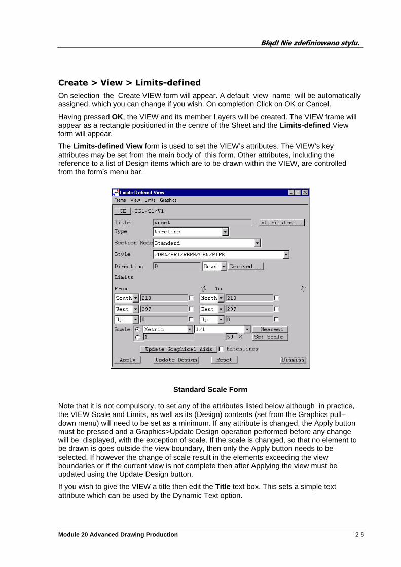
The Limits-defined View form is used to set the VIEW’s attributes. The VIEW’s key attributes may be set from the main body of this form. Other attributes, including the reference to a list of Design items which are to be drawn within the VIEW, are controlled from the form’s menu bar.
Standard Scale Form
Note that it is not compulsory, to set any of the attributes listed below although in practice, the VIEW Scale and Limits, as well as its (Design) contents (set from the Graphics pull–down menu) will need to be set as a minimum. If any attribute is changed, the Apply button must be pressed and a Graphics>Update Design operation performed before any change will be displayed, with the exception of scale. If the scale is changed, so that no element to be drawn is goes outside the view boundary, then only the Apply button needs to be selected. If however the change of scale result in the elements exceeding the view boundaries or if the current view is not complete then after Applying the view must be updated using the Update Design button.
If you wish to give the VIEW a title then edit the Title text box. This sets a simple text attribute which can be used by the Dynamic Text option.
Błąd! Nie zdefiniowano stylu.
2-6 Module 20 Advanced Drawing Production
Type option button gives a list of the available hidden–line drawing representation options, each is explained below.
Wireline gives a conventional wireline picture showing all element and ppoints. This is the quickest.
Modelled Wireline representation gives slightly greater realism by blending the intersection of primitives, but without incurring the computational overheads of removing hidden lines.
Local Hidden Line representation gives a picture where hidden lines are removed from Equipments. Where two or more Equipments overlap the elements overlapping are shown in wireline.
Global Hidden Line representation gives a picture where all hidden lines are removed.
Universal Hidden causes intersection Lines between significant elements (e.g. EQUI and STRU, SUBS and BRAN) to be generated. Note that due to the extra calculations required this is the slowest of the five.
See Appendix A for examples of the different representations and how they are displayed.
Section Mode this has two options Standard and Omit Fractional Pipe Components (sets SMOD attribute). If the latter of these is selected then any bits of components that may, result after a section, will be removed from the view displayed.
Style option button gives a list of the available Representation Rulesets (RRST elements) which may be used to control the display representation of the different parts of the Design model (as set up by your System Administrator) within the VIEW.
Direction option button allows the looking direction to be chosen.
Derived allows you to pick a Design element from which the direction will be derived, and the 3D View form will be displayed. Note that limits defined views can only have orthogonal looking directions.
Limits option buttons and text boxes may be used to set manually the Design limits of the VIEW. If the VIEW contents includes to much/little, adjust the limits to encompass a larger/small volume.
Scale option buttons allow the value and style of the VIEW scale to be selected. By selecting Set Scale the maximum scale will be calculated from the limits that have been defined with the percentage of allowable space. Once the Set Scale has been used the scale can be converted using Nearest. Selecting a different option (default Metric ) will result in the list of available scales for that option being displayed. Note the Set Scale option must be used before the other scale options will work.
Update Graphical Aids button can be used to show the effect of changes made to the scale. The view frame will be changed so that you can check quickly without the more lengthy process of updating the design graphics.
Update Design button updates the picture with the latest VIEW and Design parameters.
Błąd! Nie zdefiniowano stylu.
Module 20 Advanced Drawing Production 2-7
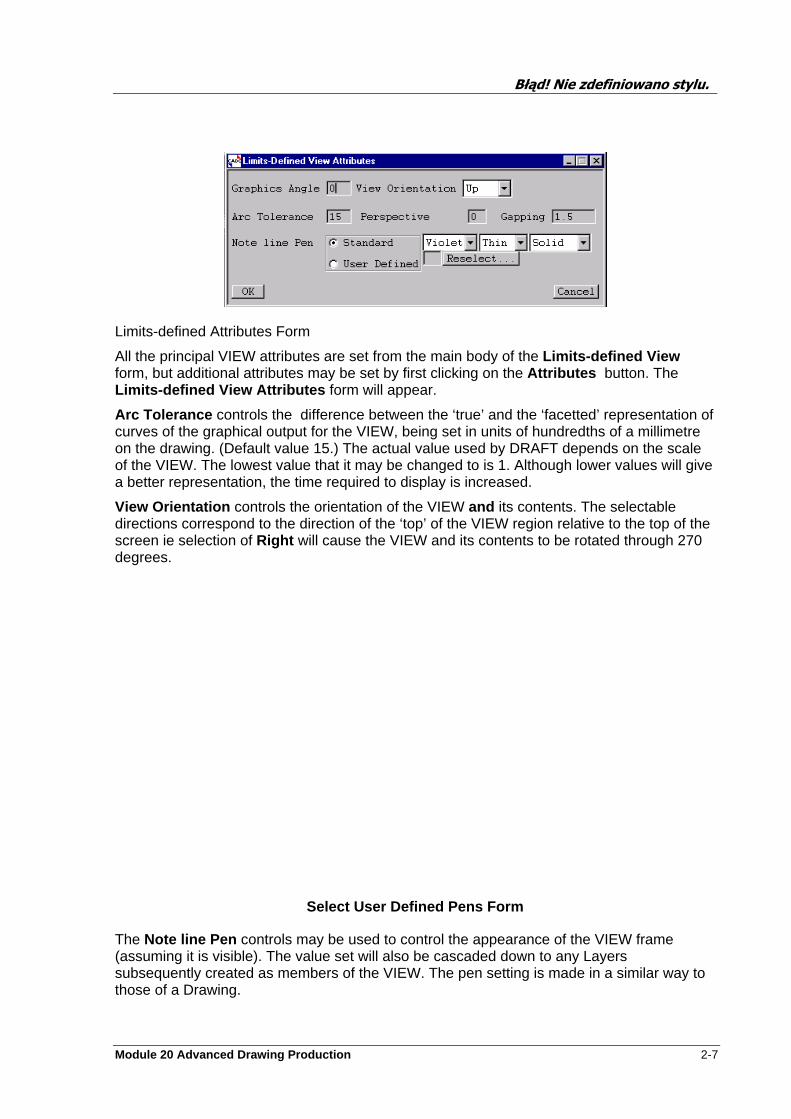
Limits-defined Attributes Form
All the principal VIEW attributes are set from the main body of the Limits-defined View form, but additional attributes may be set by first clicking on the Attributes button. The Limits-defined View Attributes form will appear.
Arc Tolerance controls the difference between the ‘true’ and the ‘facetted’ representation of curves of the graphical output for the VIEW, being set in units of hundredths of a millimetre on the drawing. (Default value 15.) The actual value used by DRAFT depends on the scale of the VIEW. The lowest value that it may be changed to is 1. Although lower values will give a better representation, the time required to display is increased.
View Orientation controls the orientation of the VIEW and its contents. The selectable directions correspond to the direction of the ‘top’ of the VIEW region relative to the top of the screen ie selection of Right will cause the VIEW and its contents to be rotated through 270 degrees.
Select User Defined Pens Form
The Note line Pen controls may be used to control the appearance of the VIEW frame (assuming it is visible). The value set will also be cascaded down to any Layers subsequently created as members of the VIEW. The pen setting is made in a similar way to those of a Drawing.
Błąd! Nie zdefiniowano stylu.
2-8 Module 20 Advanced Drawing Production
If the required settings for the Note line Pen are other than those available from the Attributes form, you may select pens which will have been defined by the DRAFT Administrator .
If the VIEW is not already displayed, select Control>Add CE from the pop-up bar menu. The VIEW will now be displayed. The ADD>CE is only for viewing and doesn’t allow you to add further information. By selecting the plus button on the Draft area (top left corner) the current sheet will be added to the list of Working Sheets .
Drawing the Picture and VIEW Manipulation
The Limits-defined View menu bar gives control over the VIEW frame and its position of the on the Sheet. Help with setting the correct limits by selecting the To-From items using the Limits option.
Control of the View Frame
The Frame pull–down menu enables you to switch the VIEW frame on or off, to control its position on the Sheet, and to control its alignment relative to any other VIEW which may be on the Sheet. Note that the size of a Standard Scale VIEW frame is determined by the VIEW’s limits and scale.
Select Frame>On/Off from the View form menu bar. This toggles the display of the VIEW frame Graphics >View Frame>On/Off (from the PDMS DRAFT General bar menu) will also hide the VIEW frame and the VIEW contents.
Frame>Position>Cursor> . . . selection enables you to use the cursor to move the VIEW frame by first nominating a point in the VIEW (its centre or a corner) from Cursor> . . .submenu. Click on the Sheet position where you wish the nominated point to move to.
Frame>Position>Explicit . . . selection enables you to move the VIEW frame by defining its Sheet position in terms of Sheet coordinates or proportions.
Following the selection, an Explicit Frame Position form will appear. The Position By Ratio text boxes can be used to position the centre of VIEW in X,Y Sheet proportions. For example, XR 0.5, YR 0.5 will put the centre of the VIEW at the centre of the Sheet.
Frame>Align selection enables you to move the current VIEW such that a specified edge (or axis) will align with the same edge (or axis) of another selected VIEW on the Sheet.
Select the edge (or axis) to be used from the Align submenu.
Use the cursor to select the VIEW with which the current VIEW is to be aligned. The current VIEW will move as specified. In the cases where the alignment would cause part or all the
Błąd! Nie zdefiniowano stylu.
Module 20 Advanced Drawing Production 2-9
view to go outside the sheet boundaries an error message will be shown and no action is taken.
Setting of Limits
The limits of a limits-defined view can be set using the Limits options on the menu at the top of the Limits-defined View form, displayed when you create or modify a View. You pick a From point and a To point which define the diagonal of the limits box.
Centre of Interest of the View
The View pull–down menu enables you to change the Design co-ordinates corresponding to the centre of interest or ‘through point’ of the VIEW.
View>Centre from the View form menu bar. The Design Centre Position form will appear. The centre of interest can be changed in three ways:
To set the through point explicitly, type the required co-ordinates into the text boxes near the top of the form, pressing Enter each time.
To set the through point as the (origin) position of a named Design element, type the element name into the Design Element text box and press Enter. The explicit co-ordinates shown on the form will change accordingly.
To set the through point as the (origin) position of a Design element which is currently displayed within the VIEW, click on the Identified button, then click on the required Design element. The limits on the View form will change accordingly.
Click on OK. Finally, to change the display of the VIEW contents, select Update Design from the Limits-define View form.
Setting the Views Contents
The Graphics pull–down menu enables you to change the Design model contents of the VIEW by modifying the VIEW’s Drawlist . The Drawlist is a list of Design items to be displayed within the VIEW. The way in which VIEWs, Drawlists and other associated elements are related is explained later.
This option enables you to add to and/or remove items from the Drawlist.
Select Graphics>Drawlist . . . from the View form menu bar. A Drawlist Management form will appear. Choose the required members from the Reference List Members list (on the left–hand side of the form), then by using the Add (or Remove ) buttons at bottom–left to add/remove the selected elements to/from the VIEW Drawlist.
Draw List Management form offers a variety of options for Drawlist creation/modification. These are listed below.
Błąd! Nie zdefiniowano stylu.
2-10 Module 20 Advanced Drawing Production
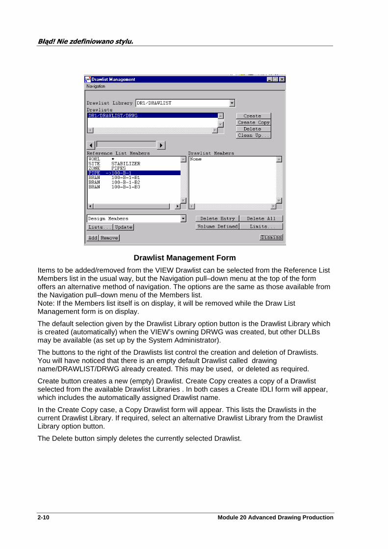
Drawlist Management Form
Items to be added/removed from the VIEW Drawlist can be selected from the Reference List Members list in the usual way, but the Navigation pull–down menu at the top of the form offers an alternative method of navigation. The options are the same as those available from the Navigation pull–down menu of the Members list. Note: If the Members list itself is on display, it will be removed while the Draw List Management form is on display.
The default selection given by the Drawlist Library option button is the Drawlist Library which is created (automatically) when the VIEW’s owning DRWG was created, but other DLLBs may be available (as set up by the System Administrator).
The buttons to the right of the Drawlists list control the creation and deletion of Drawlists. You will have noticed that there is an empty default Drawlist called drawing name/DRAWLIST/DRWG already created. This may be used, or deleted as required.
Create button creates a new (empty) Drawlist. Create Copy creates a copy of a Drawlist selected from the available Drawlist Libraries . In both cases a Create IDLI form will appear, which includes the automatically assigned Drawlist name.
In the Create Copy case, a Copy Drawlist form will appear. This lists the Drawlists in the current Drawlist Library. If required, select an alternative Drawlist Library from the Drawlist Library option button.
The Delete button simply deletes the currently selected Drawlist.

Błąd! Nie zdefiniowano stylu.
Module 20 Advanced Drawing Production 2-11
Bottom of Drawlist Management form
Volume Defined and Limits buttons (at the bottom of the form) enables the addition of all elements which are positioned wholly within a defined volume. To do this select Limits, this will display the limits form for you to define the area to be added. After setting the limits click the Volume Define button to add all elements, use remove or delete to trim down the elements displayed if required.
The Reference List Members list can contain two types of list:
• A list of Design elements (current Design element highlighted). Items selected from this list can be added to (or removed from) the VIEW’s Drawlist by using the Add and Remove buttons below the list. In this case the option button below the list will show Design Members.
• The currently selected Drawlist, together with its members and owning hierarchy. In this case, the Add and Remove buttons can be used to add (or remove) other selected Drawlists to (or from) the current VIEW Drawlist.
The Lists button can be used to display the Lists/Collections form. This form can be used to collect items from the Design database, e.g all Valves from a selected Pipe. The list of items can then be added to the Drawlist by using the Update button.
The Delete Entry button can be used to delete a selected Drawlist member. Delete All can be used when you wish to completely empty the Drawlist.
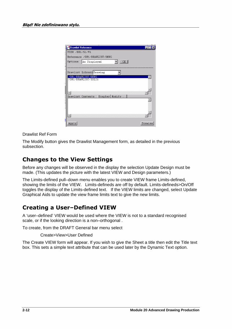
Select Graphics>Drawlist Ref . . . from the View form menu bar. A Drawlist Reference form will appear. Select the required Drawlist, this links the drawlist with this VIEW enabling only the required 3D Data, as listed in the drawlist, to be passed to this VIEW.
NOTES: The Options button allows the owning Sheet’s or the owning Drawing’s Drawlist to be used. The VIEW’s current Drawlist may be used, or the Drawlist reference may be unset. The Drawlist Library option button allows you to choose from a list of Drawlist Libraries, as set up by your System Administrator. The ‘Drawing’ selection refers to the Drawlist Library created (automatically) when the VIEWs owning Drawing was created.
Błąd! Nie zdefiniowano stylu.
2-12 Module 20 Advanced Drawing Production
Drawlist Ref Form
The Modify button gives the Drawlist Management form, as detailed in the previous subsection.
Changes to the View Settings
Before any changes will be observed in the display the selection Update Design must be made. (This updates the picture with the latest VIEW and Design parameters.)
The Limits-defined pull–down menu enables you to create VIEW frame Limits-defined, showing the limits of the VIEW. Limits-defineds are off by default. Limits-defineds>On/Off toggles the display of the Limits-defined text. If the VIEW limits are changed, select Update Graphical Aids to update the view frame limits text to give the new limits.
Creating a User–Defined VIEW
A ‘user–defined’ VIEW would be used where the VIEW is not to a standard recognised scale, or if the looking direction is a non–orthogonal .
To create, from the DRAFT General bar menu select
Create>View>User Defined
The Create VIEW form will appear. If you wish to give the Sheet a title then edit the Title text box. This sets a simple text attribute that can be used later by the Dynamic Text option.
Błąd! Nie zdefiniowano stylu.
Module 20 Advanced Drawing Production 2-13
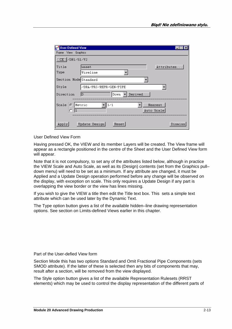
User Defined View Form
Having pressed OK, the VIEW and its member Layers will be created. The View frame will appear as a rectangle positioned in the centre of the Sheet and the User Defined View form will appear.
Note that it is not compulsory, to set any of the attributes listed below, although in practice the VIEW Scale and Auto Scale, as well as its (Design) contents (set from the Graphics pull–down menu) will need to be set as a minimum. If any attribute are changed, it must be Applied and a Update Design operation performed before any change will be observed on the display, with exception on scale. This only requires a Update Design if any part is overlapping the view border or the view has lines missing.
If you wish to give the VIEW a title then edit the Title text box. This sets a simple text attribute which can be used later by the Dynamic Text.
The Type option button gives a list of the available hidden–line drawing representation options. See section on Limits-defined Views earlier in this chapter.
Part of the User-defied View form
Section Mode this has two options Standard and Omit Fractional Pipe Components (sets SMOD attribute). If the latter of these is selected then any bits of components that may, result after a section, will be removed from the view displayed.
The Style option button gives a list of the available Representation Rulesets (RRST elements) which may be used to control the display representation of the different parts of
Błąd! Nie zdefiniowano stylu.
2-14 Module 20 Advanced Drawing Production
the Design model (covering piping, equipment and structures, as well as plot plans and clash drawings) within the VIEW.
The required looking direction may be typed into the Direction text box (DOWN is supplied as the default). The looking direction need not be orthogonal, for example N45E would be valid. The option button to the right gives the standard isometric looking directions. Selecting one of these sets the equivalent 3D direction in the Direction text box.
The Derived button, if selected, will prompt the user to identify a design element in the Graphics area for setting the Direction.
Select the Auto Scale button so the maximum scale size can be calculated then the Nearest will update the scale to the nearest fraction.
NOTE: The VIEW scale (and through point) will be calculated automatically by the Auto Scale function, and so manual changes to the scale value must left until the automatically calculated value is known.
All the principal VIEW attributes are set from the main body of the User Defined View form, but additional attributes may be set by first clicking on the Attributes . . . button. A User Defined View Attributes form will appear. This is similar to the Standard Scale View Attributes form, but offers the additional Graphics Angle facility, which can be used to define the orientation of the VIEW contents without turning the View Frame, and also the Perspective option. If a perspective view is required, type the required value into the Perspective text box (0 is supplied as the default, giving a parallel projection). This is best set after the view is in its finished View direction (set as the last function in the View creation).
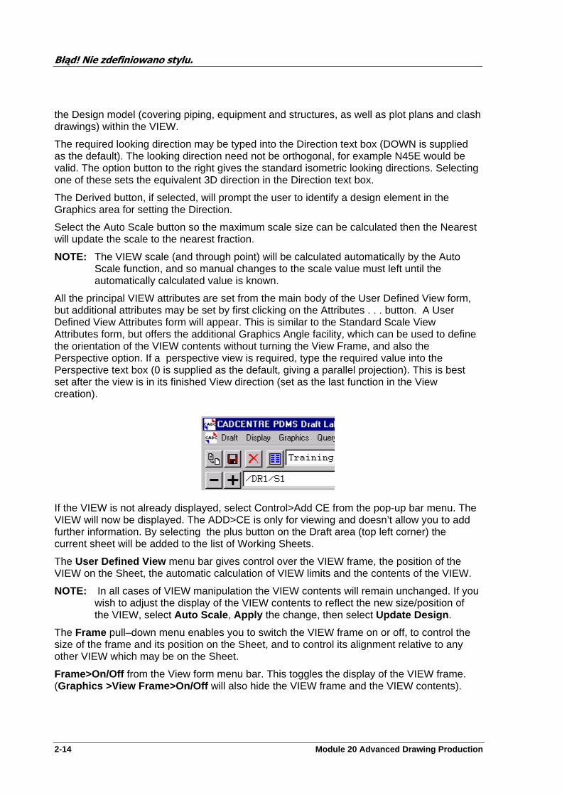
If the VIEW is not already displayed, select Control>Add CE from the pop-up bar menu. The VIEW will now be displayed. The ADD>CE is only for viewing and doesn’t allow you to add further information. By selecting the plus button on the Draft area (top left corner) the current sheet will be added to the list of Working Sheets.
The User Defined View menu bar gives control over the VIEW frame, the position of the VIEW on the Sheet, the automatic calculation of VIEW limits and the contents of the VIEW.
NOTE: In all cases of VIEW manipulation the VIEW contents will remain unchanged. If you wish to adjust the display of the VIEW contents to reflect the new size/position of the VIEW, select Auto Scale , Apply the change, then select Update Design .
The Frame pull–down menu enables you to switch the VIEW frame on or off, to control the size of the frame and its position on the Sheet, and to control its alignment relative to any other VIEW which may be on the Sheet.
Frame>On/Off from the View form menu bar. This toggles the display of the VIEW frame. (Graphics >View Frame>On/Off will also hide the VIEW frame and the VIEW contents).

Błąd! Nie zdefiniowano stylu.
Module 20 Advanced Drawing Production 2-15
The Frame>Size>Cursor> selection enables you to use the cursor to resize the VIEW frame by clicking on the opposite corners of the new VIEW region.
The Frame>Size>Explicit . . . selection enables you to resize the VIEW frame by defining its size in terms of Sheet co-ordinates or proportions.
Following the selection, an Explicit Frame Size form will appear.
Size By Ratio text boxes can be used to define the extent of VIEW in X,Y Sheet proportions. For example, From XR 0.2 To XR 0.8 would give a VIEW frame centred in the Sheet in the X direction and occupying 60% of the Sheet width. Setting the XR (or YR) values will cause the Width (or Height ) values to change automatically. Conversely, setting the Width/Height values will cause the XR/YR values to change automatically (giving a VIEW frame centred on the Sheet in the appropriate direction).
Similar considerations apply to the Size By Co–ordinates sizing option.
Frame>Copy Size> . . . selection enables you to use the cursor to resize the VIEW frame by copying the Width or Height of another VIEW on the Sheet.
For example, Frame>Copy Size>Width will ask you to identify (with the cursor) a VIEW whose width you wish to copy. The width of the current VIEW will then change to be the same as that of the identified VIEW.
Frame>Position>Cursor> . . . selection enables you to use the cursor to move the VIEW frame by first nominating a point in the VIEW (its centre or a corner) from Cursor> . . . submenu. The nominated point will move to the cursor position when the left–hand mouse button is clicked.
Frame>Position>Explicit . . . selection enables you to move the VIEW frame by defining its Sheet position in terms of Sheet co-ordinates or proportions.
Following the selection, an Explicit Frame Position form will appear. The Position By Ratio text boxes can be used to position the centre of the VIEW in X,Y Sheet proportions. For example, XR 0.5, YR 0.5 will put the centre of the VIEW at the centre of the Sheet.
Frame>Align . . . selection enables you to move the current VIEW such that a specified edge (or axis) will align with the same edge (or axis) of another selected VIEW on the Sheet. This function thus makes it easier to butt VIEWs against each other on the Sheet.
1. Select the edge (or axis) to be used from the Align submenu.
2. Use the cursor to select the VIEW with which the current VIEW is to be aligned. The current VIEW will move as specified.
The View pull–down menu enables you to change the Design co-ordinates corresponding to the centre of interest or ‘through point’ of the VIEW
View>Centre. . . from the View form menu bar gives the choice of four options:
1. Select View>Centre>Identify to set the through point as the (origin) position of a Design element which is currently displayed within the VIEW. Click on the required Design element. The limits on the View form will change accordingly.
2. Select View>Centre>Cursor to centre the view about a cursor hit position.

Błąd! Nie zdefiniowano stylu.
2-16 Module 20 Advanced Drawing Production
3. Select View>Centre>By Cursor will require two cursor hits, one for an origin and one for the displacement from the origin for the centre of the view.
4. View>Centre>Explicit will display the Design Centre Position form. Type the required co-ordinates into the text boxes near the top of the form, pressing Enter each time. Click on OK to change the settings.
Finally, to change the display of the VIEW contents, select Graphics>Update Design from the View form menu bar.
Selection of View>Offset from the View form menu bar will display the Design Graphics Offset form. You may type in XY values for which the Design view will be offset with respect to the Frame Centre. Select OK to activate this form.
The Graphics pull–down menu enables you to change the Design model content of the VIEW by modifying the VIEW’s Drawlist .
The Graphics pull–down menu operations are exactly the same as those for a Standard Scale (or Limits-defined) VIEW .
Creating Detail VIEWs
This facility enables you to create a ‘detail view’ (existing as a VIEW element) which would be a ‘zoomed in’ view of a specified part of the current view, the detail view being placed elsewhere on the same or on separate sheet.
The creation procedure may be summarised as:
Specify the area on the current VIEW to be Detailed .
1. Specify and position the annotation for the detail VIEW.
2. Define a rectangular area on the Sheet which is to be occupied by the detail VIEW.
3. Modify the detail VIEW as required.
Proceed as follows:
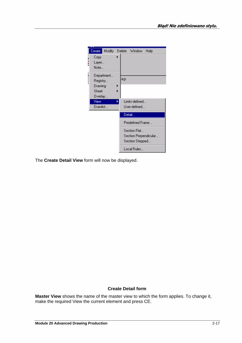
Select Create>View>Detail . . . from the General menu. If the VIEW from which the detail VIEW is to be created (the ‘master VIEW’) is not the current element, you will be asked to cursor–identify a displayed element within it, thus making the master VIEW current.
Błąd! Nie zdefiniowano stylu.
Module 20 Advanced Drawing Production 2-17
The Create Detail View form will now be displayed.
Create Detail form
Master View shows the name of the master view to which the form applies. To change it, make the required View the current element and press CE.
Błąd! Nie zdefiniowano stylu.
2-18 Module 20 Advanced Drawing Production
Reference text box allows you to enter a reference ID for the detail. The reference is used in naming the local detail note and must not contain any spaces. This reference is also set at the newly created detail view as a UDA and is referred to in the relevant note texts.
Detail Sheet shows the sheet in which the detail view will be created. To change it, make the required Sheet the current element and press CE. The default is Local, meaning the detail view will be created on the same sheet as the Master view
Goto >> and Return << buttons navigate between the detail Master View and the detail sheet respectively.
Display will show the reference sheet
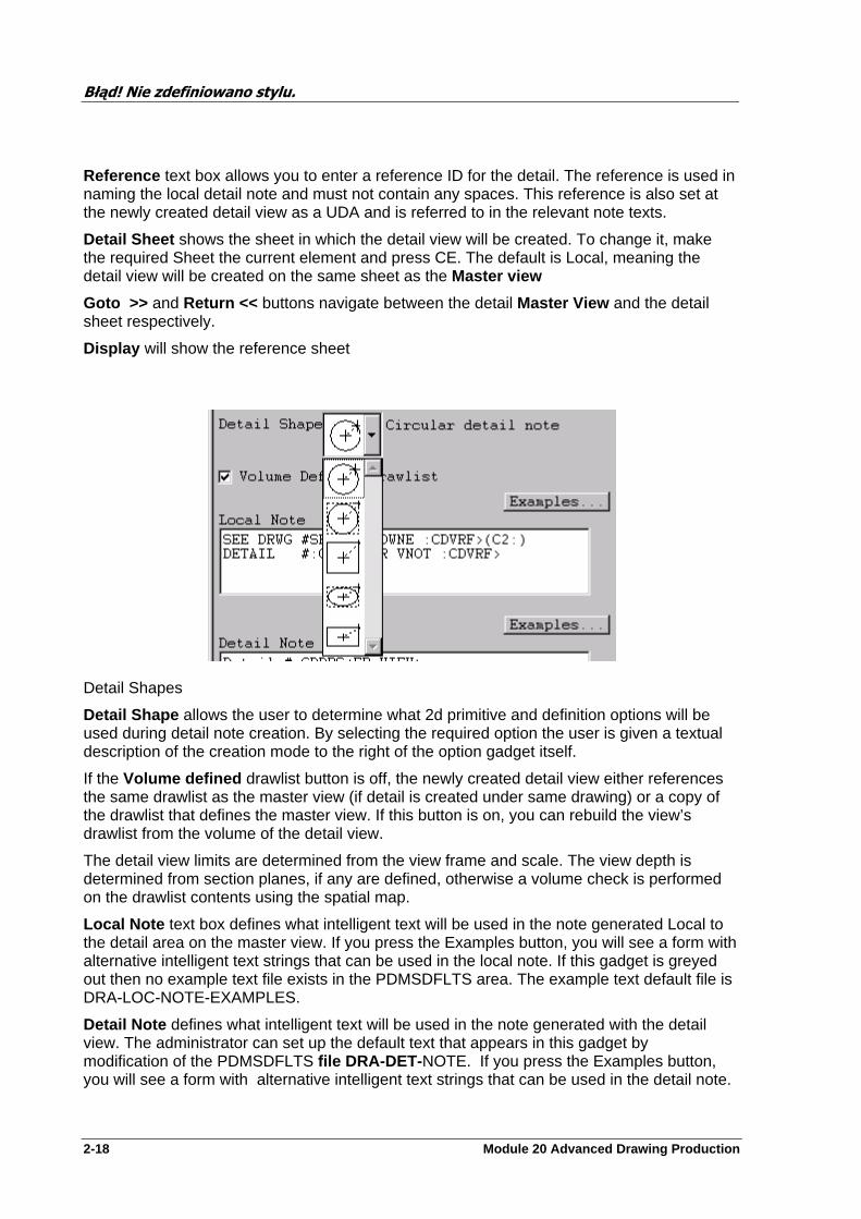
Detail Shapes
Detail Shape allows the user to determine what 2d primitive and definition options will be used during detail note creation. By selecting the required option the user is given a textual description of the creation mode to the right of the option gadget itself.
If the Volume defined drawlist button is off, the newly created detail view either references the same drawlist as the master view (if detail is created under same drawing) or a copy of the drawlist that defines the master view. If this button is on, you can rebuild the view’s drawlist from the volume of the detail view.
The detail view limits are determined from the view frame and scale. The view depth is determined from section planes, if any are defined, otherwise a volume check is performed on the drawlist contents using the spatial map.
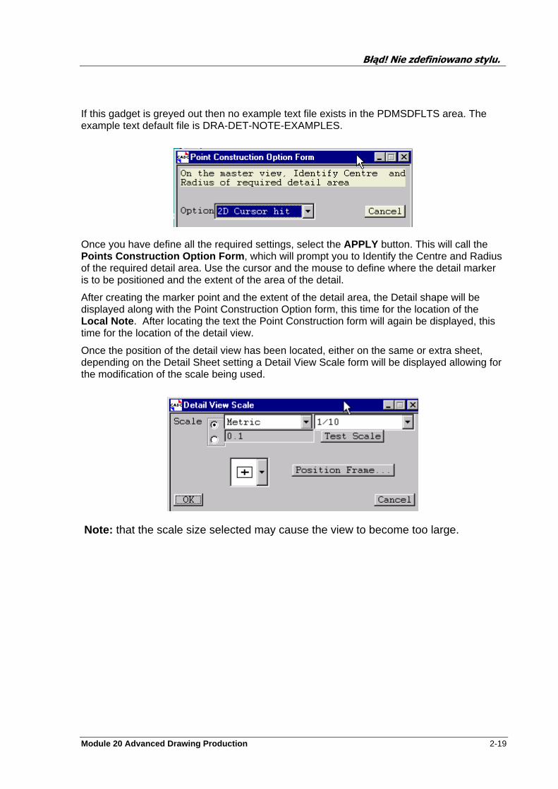
Local Note text box defines what intelligent text will be used in the note generated Local to the detail area on the master view. If you press the Examples button, you will see a form with alternative intelligent text strings that can be used in the local note. If this gadget is greyed out then no example text file exists in the PDMSDFLTS area. The example text default file is DRA-LOC-NOTE-EXAMPLES.
Detail Note defines what intelligent text will be used in the note generated with the detail view. The administrator can set up the default text that appears in this gadget by modification of the PDMSDFLTS file DRA-DET- NOTE. If you press the Examples button, you will see a form with alternative intelligent text strings that can be used in the detail note.
Błąd! Nie zdefiniowano stylu.
Module 20 Advanced Drawing Production 2-19
If this gadget is greyed out then no example text file exists in the PDMSDFLTS area. The example text default file is DRA-DET-NOTE-EXAMPLES.
Once you have define all the required settings, select the APPLY button. This will call the Points Construction Option Form , which will prompt you to Identify the Centre and Radius of the required detail area. Use the cursor and the mouse to define where the detail marker is to be positioned and the extent of the area of the detail.
After creating the marker point and the extent of the detail area, the Detail shape will be displayed along with the Point Construction Option form, this time for the location of the Local Note . After locating the text the Point Construction form will again be displayed, this time for the location of the detail view.
Once the position of the detail view has been located, either on the same or extra sheet, depending on the Detail Sheet setting a Detail View Scale form will be displayed allowing for the modification of the scale being used.
Note: that the scale size selected may cause the view to become too large.
Błąd! Nie zdefiniowano stylu.
2-20 Module 20 Advanced Drawing Production
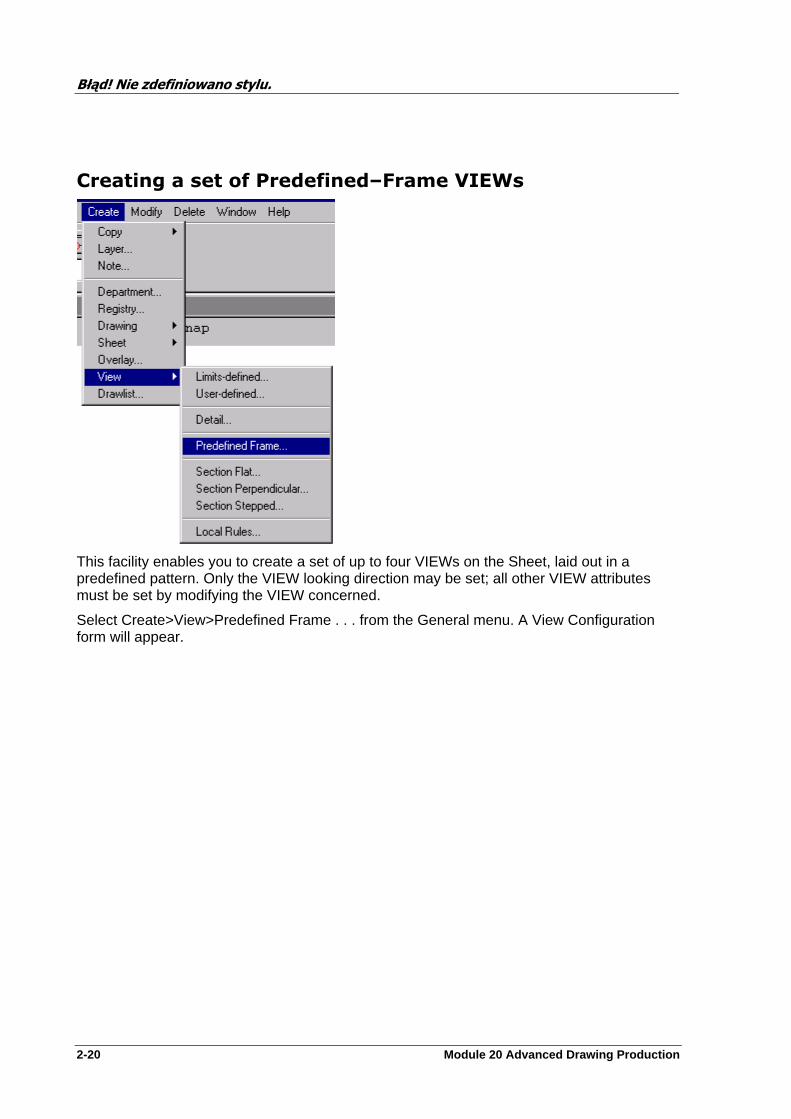
Creating a set of Predefined–Frame VIEWs
This facility enables you to create a set of up to four VIEWs on the Sheet, laid out in a predefined pattern. Only the VIEW looking direction may be set; all other VIEW attributes must be set by modifying the VIEW concerned.
Select Create>View>Predefined Frame . . . from the General menu. A View Configuration form will appear.
Błąd! Nie zdefiniowano stylu.
Module 20 Advanced Drawing Production 2-21
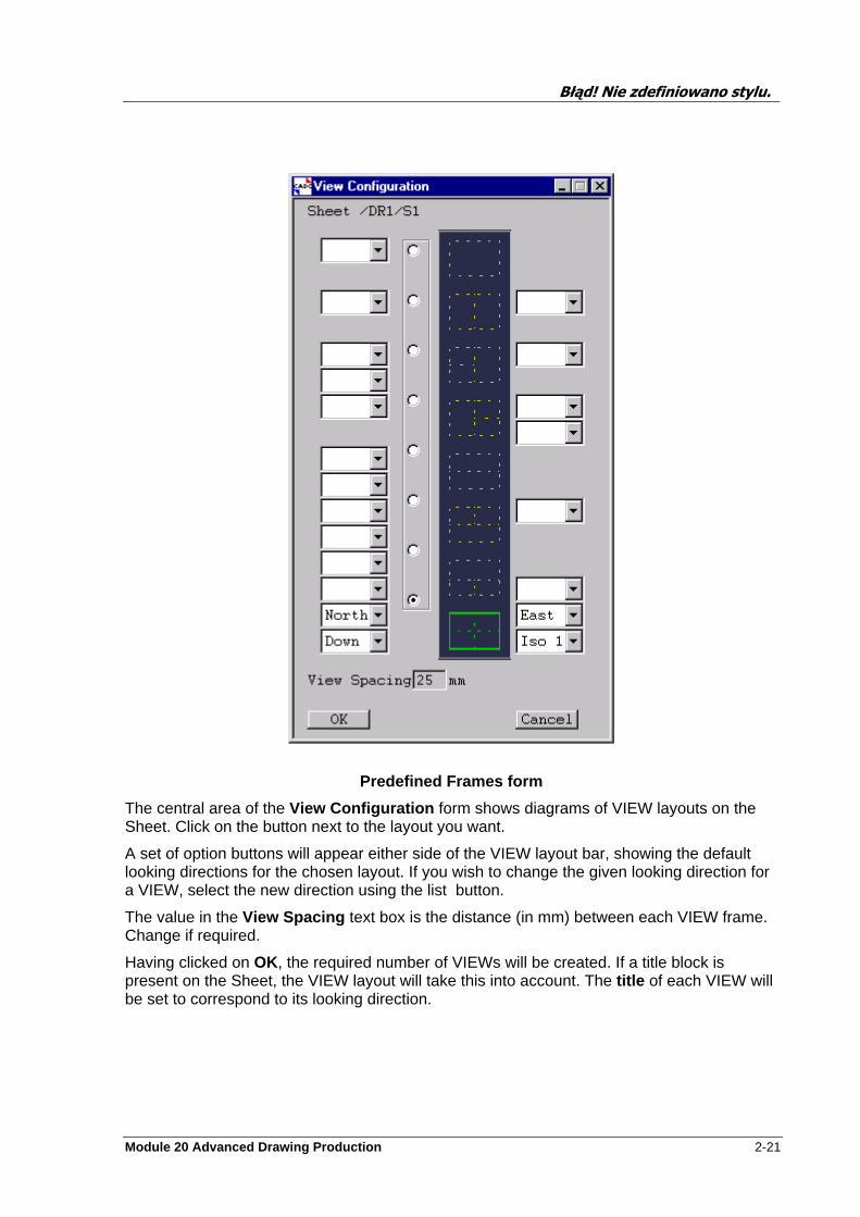
Predefined Frames form
The central area of the View Configuration form shows diagrams of VIEW layouts on the Sheet. Click on the button next to the layout you want.
A set of option buttons will appear either side of the VIEW layout bar, showing the default looking directions for the chosen layout. If you wish to change the given looking direction for a VIEW, select the new direction using the list button.
The value in the View Spacing text box is the distance (in mm) between each VIEW frame. Change if required.
Having clicked on OK, the required number of VIEWs will be created. If a title block is present on the Sheet, the VIEW layout will take this into account. The title of each VIEW will be set to correspond to its looking direction.
Błąd! Nie zdefiniowano stylu.
2-22 Module 20 Advanced Drawing Production
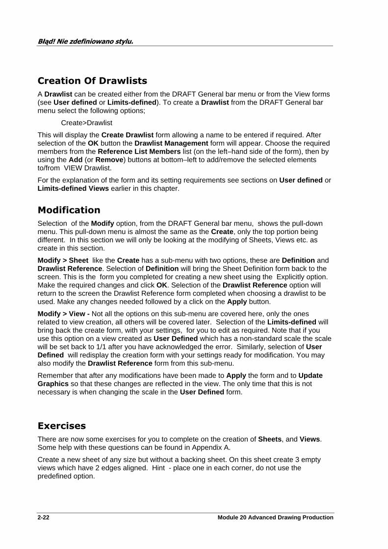
Creation Of Drawlists
A Drawlist can be created either from the DRAFT General bar menu or from the View forms (see User defined or Limits-defined ). To create a Drawlist from the DRAFT General bar menu select the following options;
Create>Drawlist
This will display the Create Drawlist form allowing a name to be entered if required. After selection of the OK button the Drawlist Management form will appear. Choose the required members from the Reference List Members list (on the left–hand side of the form), then by using the Add (or Remove ) buttons at bottom–left to add/remove the selected elements to/from VIEW Drawlist.
For the explanation of the form and its setting requirements see sections on User defined or Limits-defined Views earlier in this chapter.
Modification
Selection of the Modify option, from the DRAFT General bar menu, shows the pull-down menu. This pull-down menu is almost the same as the Create , only the top portion being different. In this section we will only be looking at the modifying of Sheets, Views etc. as create in this section.
Modify > Sheet like the Create has a sub-menu with two options, these are Definition and Drawlist Reference . Selection of Definition will bring the Sheet Definition form back to the screen. This is the form you completed for creating a new sheet using the Explicitly option. Make the required changes and click OK. Selection of the Drawlist Reference option will return to the screen the Drawlist Reference form completed when choosing a drawlist to be used. Make any changes needed followed by a click on the Apply button.
Modify > View - Not all the options on this sub-menu are covered here, only the ones related to view creation, all others will be covered later. Selection of the Limits-defined will bring back the create form, with your settings, for you to edit as required. Note that if you use this option on a view created as User Defined which has a non-standard scale the scale will be set back to 1/1 after you have acknowledged the error. Similarly, selection of User Defined will redisplay the creation form with your settings ready for modification. You may also modify the Drawlist Reference form from this sub-menu.
Remember that after any modifications have been made to Apply the form and to Update Graphics so that these changes are reflected in the view. The only time that this is not necessary is when changing the scale in the User Defined form.
Exercises
There are now some exercises for you to complete on the creation of Sheets , and Views . Some help with these questions can be found in Appendix A.
Create a new sheet of any size but without a backing sheet. On this sheet create 3 empty views which have 2 edges aligned. Hint - place one in each corner, do not use the predefined option.

Błąd! Nie zdefiniowano stylu.
Module 20 Advanced Drawing Production 2-23
Now create a 4th view by copying one of the other views using the options available on the top bar menus.
Using the templates set-up on your machine create a sheet. How does it differ from what you did in Q. 1?
Using the Predefined option create a sheet with 3 view in any layout. Put a backing sheet on before you create the views. What happens?
Now create a A0 sheet which has one view. This view should cover as much of the unused area of the sheet as possible. Into this view add all the Design Equipment. Elements in plan view. Try some of the different representation types.
Create a Limits-defined view and add the Pipework and equipment. Try changing the percentage of paper user from the default 50%.
Create a detail view of an item of equipment.
Modify the views created in Q. 1 to display any item of equipment using at least three different look directions.
What problems can be encounter by changing the contents of a Drawlist?

Module 20 Advanced Drawing Production 3-1
Dimensioning
Changing Application
To enter the Dimensioning Application select the following from the DRAFT General bar menu:
Draft > Dimensioning
This will close the application you are currently running and load the Dimensioning application. Change of application can be carried out from any DRAFT applications ie.
Dimensioning ---- 2D Drafting or Labels ----------- General and so on.
This can also be achieved by selection of the correct icon from the Draft top bar menu.
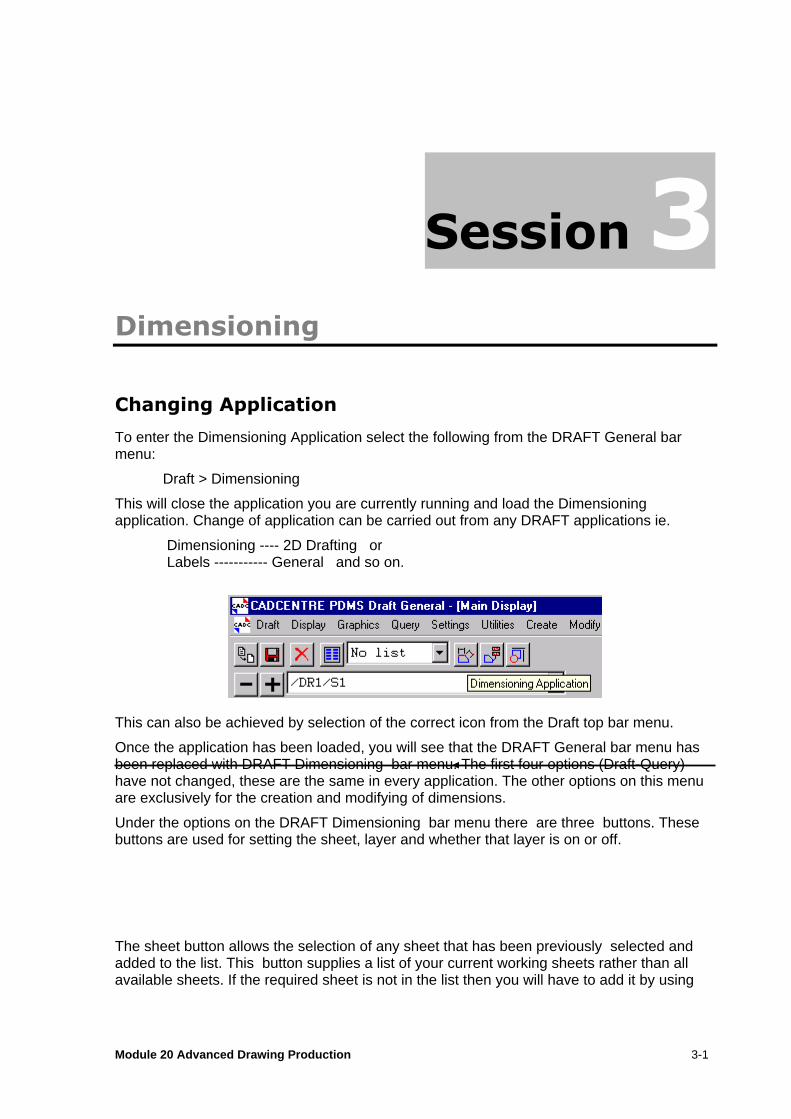
Once the application has been loaded, you will see that the DRAFT General bar menu has been replaced with DRAFT Dimensioning bar menu. The first four options (Draft-Query) have not changed, these are the same in every application. The other options on this menu are exclusively for the creation and modifying of dimensions.
Under the options on the DRAFT Dimensioning bar menu there are three buttons. These buttons are used for setting the sheet, layer and whether that layer is on or off.
The sheet button allows the selection of any sheet that has been previously selected and added to the list. This button supplies a list of your current working sheets rather than all available sheets. If the required sheet is not in the list then you will have to add it by using

Błąd! Nie zdefiniowano stylu.
3-2 Module 20 Advanced Drawing Production
Draft > Select Work Sheet option. This will display the Drawing Selection form. Select the required DEPT, REGI, DRWG and Sheet and click the OK button.
If the element required has been created since you first entered DRAFT or since your last update of this form, use the Re-load button in the top right hand corner of the form. This will Re-load the full Members List into this form. Having completed this select your required Sheet.
A sheet may also be added to the working sheet list by navigating to the element and selecting the plus key on the form main menus (shown above).
Selection of a sheet from the above from DRAFT main bar menu causes the selected sheet to be added to the Main Display.
The Layers button allows you to make all items held by that Layer to either invisible (OFF) or visible (ON).
The button positioned to the right of the ON/OFF button lists all the Layers which are currently owned by your current View who’s Purpose attribute is set to DIM or RAD or any other Purpose defined to be used for Dimensioning. Layers which have their PUR attribute set to something other than DIM or RAD or other defined Dimensioning Purpose will not be displayed in this application.
Note: Other Layer Purposes may be defined by the Draft Administrator for use with Dimensioning.
Dimensioning Hierarchy
This section covers only the part of the DRAFT Hierarchy that relates to Dimensioning. Below is a diagram showing the related elements and at what level in the hierarchy they may be created. All of these elements, with the exception of extra Layers, will be created automatically as you dimension your View.
Błąd! Nie zdefiniowano stylu.
Module 20 Advanced Drawing Production 3-3
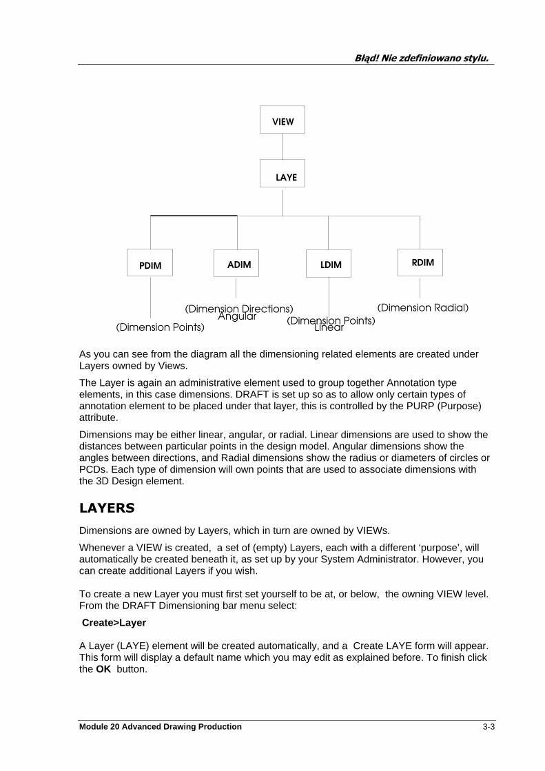
As you can see from the diagram all the dimensioning related elements are created under Layers owned by Views.
The Layer is again an administrative element used to group together Annotation type elements, in this case dimensions. DRAFT is set up so as to allow only certain types of annotation element to be placed under that layer, this is controlled by the PURP (Purpose) attribute.
Dimensions may be either linear, angular, or radial. Linear dimensions are used to show the distances between particular points in the design model. Angular dimensions show the angles between directions, and Radial dimensions show the radius or diameters of circles or PCDs. Each type of dimension will own points that are used to associate dimensions with the 3D Design element.
LAYERS
Dimensions are owned by Layers, which in turn are owned by VIEWs.
Whenever a VIEW is created, a set of (empty) Layers, each with a different ‘purpose’, will automatically be created beneath it, as set up by your System Administrator. However, you can create additional Layers if you wish. To create a new Layer you must first set yourself to be at, or below, the owning VIEW level. From the DRAFT Dimensioning bar menu select:
Create>Layer A Layer (LAYE) element will be created automatically, and a Create LAYE form will appear. This form will display a default name which you may edit as explained before. To finish click the OK button.
LAYE
VIEW
(Dimension Directions)(Dimension Points)
LDIMADIM RDIM
(Dimension Radial)
PDIM
(Dimension Points)Angular
Linear
Błąd! Nie zdefiniowano stylu.
3-4 Module 20 Advanced Drawing Production
The Layer you have just created will appear in the Layer scrollable list with its Purpose set to DIM. This is because it was created from within the Dimensioning application. If created from any other application then the Purpose will be defined to relating to that application, therefore the Purpose will need to be altered if used form Dimensioning.
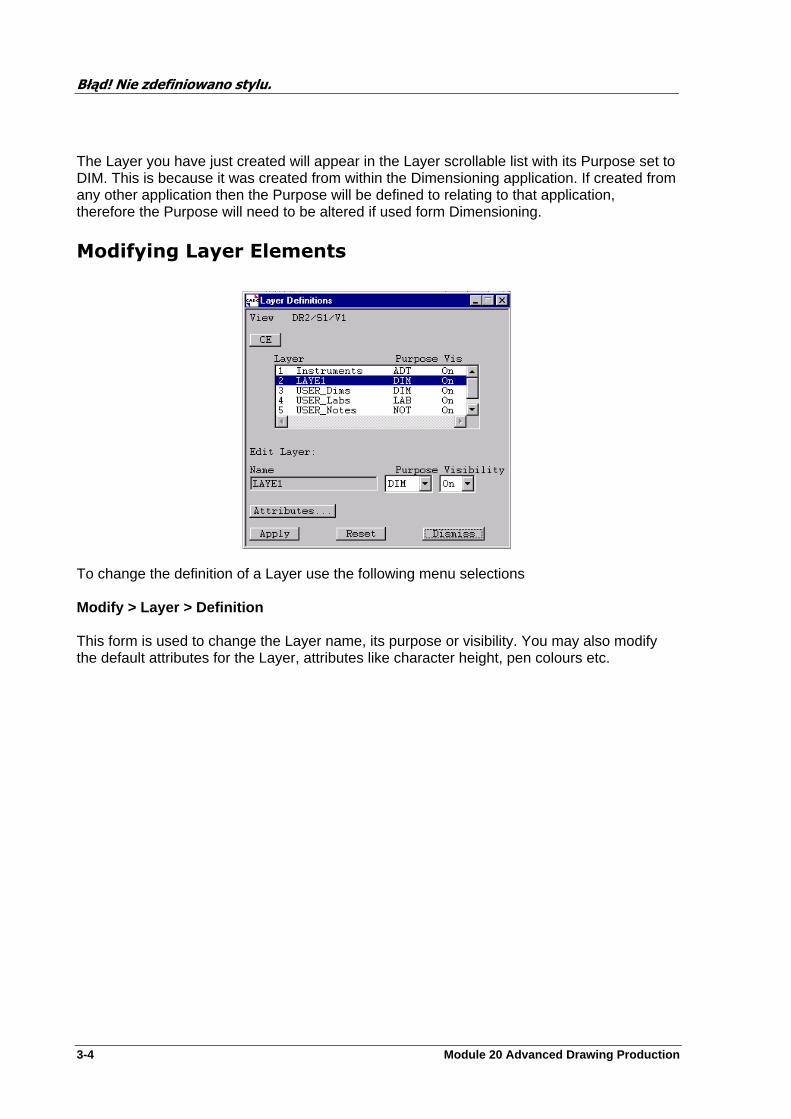
Modifying Layer Elements
To change the definition of a Layer use the following menu selections Modify > Layer > Definition This form is used to change the Layer name, its purpose or visibility. You may also modify the default attributes for the Layer, attributes like character height, pen colours etc.
Błąd! Nie zdefiniowano stylu.
Module 20 Advanced Drawing Production 3-5
Layer Definition Form
On this form there is a scrollable list which shows all the layers owned by the current View. If you change the View the list may be updated by selection of the CE (Current Element) button. Scroll up/down the list until the required Layer is shown. Now move the cursor onto the list member and click the left mouse key, this selects it. The act of selection causes the list item to be highlighted and the other fields of the form to change to the current settings of the selected Layer.
To change the Layer name, simply select the field and type in any changes that are required.
Purpose . The button displays a list of all the possible settings for this attribute. You should now select the required option for this Layer.
Visibility . This is a simple toggle switch ON/OFF. Off removes any items located on this Layer from the display in the Area View. On will display them. Attributes . This calls the DIM Layer Attributes form which is explained below.
To change any of the attributes which are currently set use the menu selection to display DIM Layer Attributes form Modfiy > Layer > Attributes This contains the setting option buttons for many of the attributes for Dimensioning.
Most of the buttons are set by placing the cursor over the button and holding the left mouse key down. Move the cursor over the list, still holding the key down, until you find the required selection. The other type is a simple text field, which is set by moving the cursor into the field and clicking the mouse key. You may now enter the required setting.
The setting of the units of the Layer will result in any output like the creation of Dimensions to use the unit type selected. If you require your Dimensions to be displayed in Feet & Inches then you should make this selection. A Layer may only use one type of unit, therefore if you require both metric and imperial units you will need to have a second Layer . The setting of the units to be used is held by the Layer attribute UCOD (unit co-ordinate)
When setting the defaults for Character Height, Text Pen, and Fonts there are toggle buttons that is set ON will take the settings for these attributes directly from the defining template. The local option will take its defaults from the local setting. The setting to templates is only of use when creating element that come from a Draft Library, such as Symbolic Labels or Symbols.

Błąd! Nie zdefiniowano stylu.
3-6 Module 20 Advanced Drawing Production
On the right of the form, for Projection and Dim Line Pens, there is the ability to use one of the User-Defined pens. These pens are defined by the DRAFT Administrator.
To select a User Defined Pen click on the button Reselect . This causes the Select User-Defined Pen form to be displayed. This form has a scrollable list showing the 40 different line styles with colour available for selection.. To change the displayed page simply click either the Up or Down buttons. Once the required pen style is shown it may be selected by clicking the Cursor Selection button, then move the cursor on to either the number or graphical display and click the mouse key. The selection of the pen will be shown in the Pen Number box. You may enter the required number directly via the keyboard, after selection of the field. After the correct selection has been made click the OK button. This will write the selected pen number to the DIM Layer Attributes form.
If you know the pen number then you may enter it directly onto the DIM Layer Attributes form. Once you have the pens information there is a toggle button which switches the active pen to either the User Defined or the Standard pen. Remember that when the button is pressed in it is active (ON).
After completion of this form click the Apply button.
Modify>Layer > Members . This activates the Layer Members form. This form allows you to move elements from one Layer to another. To do this select the Layer that the elements will be moved to from the Layer button. Note that this selection must be made first as it resets the other options. Now choose from which Layer that the elements are to be moved from by selection from the Include Members from Layer . Now select either all the elements to be moved or use the Select All button to select all elements under that selected Layer . When all is correct click the Apply button.
Błąd! Nie zdefiniowano stylu.
Module 20 Advanced Drawing Production 3-7
Creating Linear Dimensions
The simplest kind of Linear Dimension consists of a pair of points on a drawing, each of which relates to a point in the Design model. From each of these Dimension Points on the drawing, a projection line is drawn in a user–definable direction; between these parallel projection lines, dimension lines are drawn. Each dimension and projection line may have text associated with it.
Before you start creating Dimensions make sure that you have set the Layer buttons, on the DRAFT Dimensioning form, to show the correct Layer for these new Dimensions.
Creating Linear Dimension
To create a Linear Dimension you must have a 2D View on display which includes the VIEW within which you wish to create the Dimension.
Select Create>Dimension Linear from the Dimensioning Menu. A Create Linear Dimension form will appear.
Linear Dimension Form
Notes concerning this form are:
The dimension types given by the Type option button are Chain (chained), Tail (parallel) or Truncate (truncated parallel).
Direction , the value entered in the text box specifies the offset from the direction selected from the left–hand option button. The list given by the right–hand option button will change according to the direction selected from the left–hand button. The direction relates to the
Błąd! Nie zdefiniowano stylu.
3-8 Module 20 Advanced Drawing Production
directions in the DESIGN DB. The True option allows for the dimensioning of ‘true length’ between dimension points.
Derived Direction This option allows you to find out the direction of an element or between PPoints from the DESIGN DB and to use it to set the direction used for the dimensions.
Terminator button allows you select what symbol will be displayed at the termination of a Dimension line, if at all. You may choose from Arrows , Dots , Obliques or Off .
First Terminator button allows you to set a different terminator for the first dimension line than that used for all the others. Note is function is only available for the Truncate type of dimensions.
The Projection Line text options given by the Text option button are:
Off -no text
Item Name -name of hit item
CL Item Name -name of hit item, preceded by centreline symbol
Pipe Name -name of hit Pipe
Pipe Name BOP EL ARR -name of hit Pipe, followed by elevation of arrive point of hit Component
Pipe Name BOP EL LEA -name of hit Pipe, followed by elevation of leave point of hit Component
CL Pipe Name -name of hit Pipe, preceded by centreline symbol
Equip. Name -name of hit Equipment
CL Equip. Name -name of hit Equipment, preceded by centreline symbol
Geo. Coord -geographical co-ordinate (Dimension direction axis)
Dat. Coord -datum co-ordinate (e.g. SITE co-ordinate)
The Angle option allows the setting of the Projection Line direction. The default direction is 90o to the Dimension Line.
Linear/Angular Dimension Creation Form

Błąd! Nie zdefiniowano stylu.
Module 20 Advanced Drawing Production 3-9
After setting this form as required click the OK button to activate. This will cause the Linear/Angular Dimension form to be displayed.
This form is used to create the points which are used to create the Dimensions and forms the link with the 3D-Model element. There are three different types of point which may be created, each being used for a special sort of dimensioning. The point types are DPPT (Dimension Point/Point element), DPBA (Dimension Point Before/After), and DPOI (Dimension Point).
Selection from the list, given in the panel to the left of the form, allows you to choose the type of point to be created. The type of point created will be determined the selection from the list
eg DPPT --- created from ITEM, DPPT---created from PPOINT, DPBA ---created from BEFORE, DPOI---created from 3D POS.
Item . This will create the dimension point (DPPT type) at the P0 of the design primitive.
Owner . This will create the dimension point (DPPT type) at the Equipment Origin of the element.
Before /After . This creates a Linear Dimension making use of the Design P-Point of the element. The Before option will select the edge that precedes the P0 in the direction set for dimensioning, After is the edge after. Creates a DPBA type point.
PPoint option (i.e. position the Dimension Point at a p–point). Creates a DPPT type point.
Pline Any End . Allows you to use Plines for steelwork rather than P-Points. Creates a DPPT type point.
Pline Prop’n. Allows you to use Plines for steelwork rather than P-Points. You will be prompted to identify a proportion along a Pline to be dimensioned.
3D Pos . Calls the 3D Position form to allow you to enter an explicit set of co-ordinates. Creates a DPOI type point.
3D Cursor . Using the cursor you may select a position. Creates a DPOI type point.
Matchline option can only be used with Limits-defined VIEWs.
NOTE: You can only position to a matchline; a dimension point positioned using this option must be the last of a series.
Create If you wish to create Dimension Points one at a time (essential if you wish to create successive points with different positioning controls, or if you wish to use the 3D Pos , Cursor or Matchline positioning controls), click on Create .
Create button will normally have to be selected for each point. A suitable message will be displayed in the status area, depending on the selected positioning option, except for 3D Pos when a 3D Position form will be displayed. In this case, enter the required co-ordinates into the text–entry boxes on the form.
If Automatic repeat dimensioning is required, depress the square button to the right of the Create option before the Create button is selected.
Click with the mouse on the position where you wish the Dimension Point to be created. Repeat this procedure until the required number of Dimension Points have been created. If
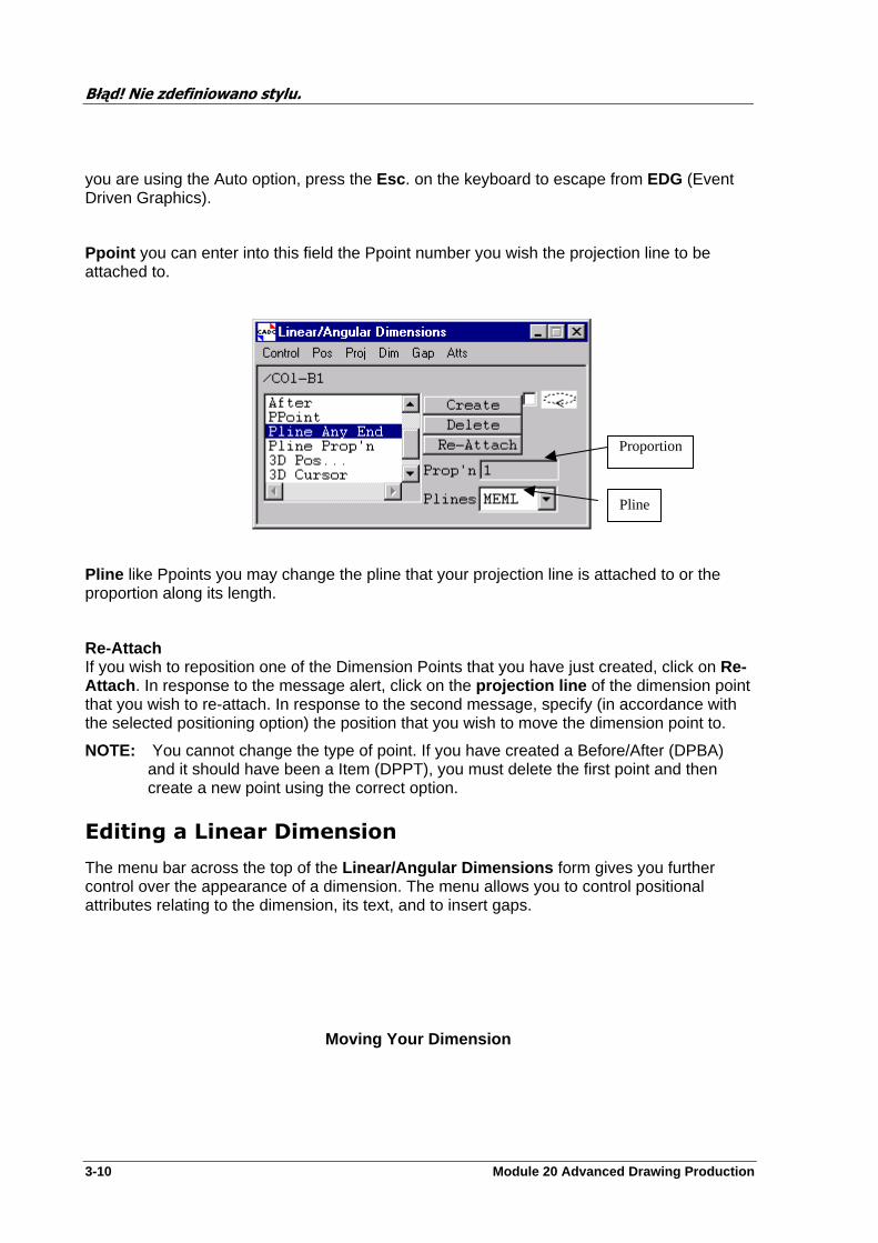
Błąd! Nie zdefiniowano stylu.
3-10 Module 20 Advanced Drawing Production
you are using the Auto option, press the Esc . on the keyboard to escape from EDG (Event Driven Graphics).
Ppoint you can enter into this field the Ppoint number you wish the projection line to be attached to.
Pline like Ppoints you may change the pline that your projection line is attached to or the proportion along its length.
Re-Attach If you wish to reposition one of the Dimension Points that you have just created, click on Re-Attach . In response to the message alert, click on the projection line of the dimension point that you wish to re-attach. In response to the second message, specify (in accordance with the selected positioning option) the position that you wish to move the dimension point to.
NOTE: You cannot change the type of point. If you have created a Before/After (DPBA) and it should have been a Item (DPPT), you must delete the first point and then create a new point using the correct option.
Editing a Linear Dimension
The menu bar across the top of the Linear/Angular Dimensions form gives you further control over the appearance of a dimension. The menu allows you to control positional attributes relating to the dimension, its text, and to insert gaps.
Moving Your Dimension
Proportion
Pline
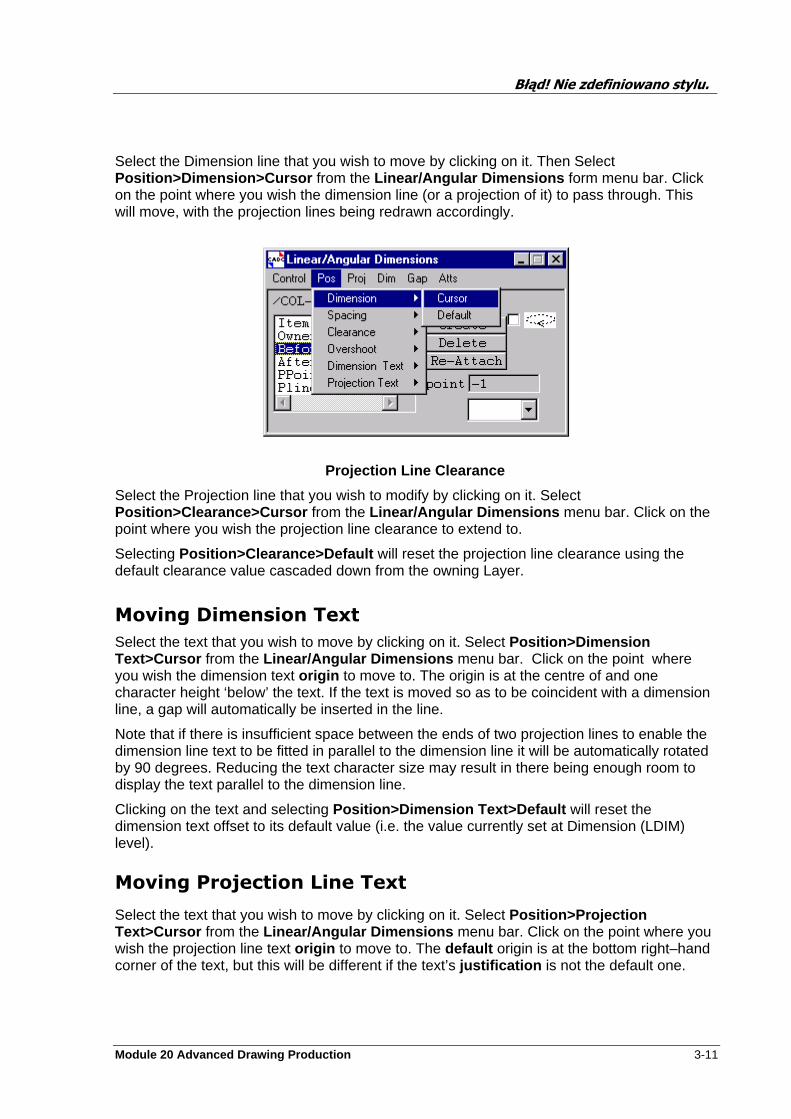
Błąd! Nie zdefiniowano stylu.
Module 20 Advanced Drawing Production 3-11
Select the Dimension line that you wish to move by clicking on it. Then Select Position>Dimension>Cursor from the Linear/Angular Dimensions form menu bar. Click on the point where you wish the dimension line (or a projection of it) to pass through. This will move, with the projection lines being redrawn accordingly.
Projection Line Clearance
Select the Projection line that you wish to modify by clicking on it. Select Position>Clearance>Cursor from the Linear/Angular Dimensions menu bar. Click on the point where you wish the projection line clearance to extend to.
Selecting Position>Clearance>Default will reset the projection line clearance using the default clearance value cascaded down from the owning Layer.
Moving Dimension Text
Select the text that you wish to move by clicking on it. Select Position>Dimension Text>Cursor from the Linear/Angular Dimensions menu bar. Click on the point where you wish the dimension text origin to move to. The origin is at the centre of and one character height ‘below’ the text. If the text is moved so as to be coincident with a dimension line, a gap will automatically be inserted in the line.
Note that if there is insufficient space between the ends of two projection lines to enable the dimension line text to be fitted in parallel to the dimension line it will be automatically rotated by 90 degrees. Reducing the text character size may result in there being enough room to display the text parallel to the dimension line.
Clicking on the text and selecting Position>Dimension Text>Default will reset the dimension text offset to its default value (i.e. the value currently set at Dimension (LDIM) level).
Moving Projection Line Text
Select the text that you wish to move by clicking on it. Select Position>Projection Text>Cursor from the Linear/Angular Dimensions menu bar. Click on the point where you wish the projection line text origin to move to. The default origin is at the bottom right–hand corner of the text, but this will be different if the text’s justification is not the default one.
Błąd! Nie zdefiniowano stylu.
3-12 Module 20 Advanced Drawing Production
Clicking on the text and selecting Position>Projection Text>Default will reset the projection text offset to its default value (i.e. the value currently set at Dimension (LDIM) level).
Projection Line Text Justification
Select the text that you wish to rejustify by clicking on it. Select Projection>Justification from the Linear/Angular Dimensions menu bar. Select the required justification from the submenu. Towards is the default. Towards sets the text so that the first character is towards the dimension line. Centre sets the middle character and Away aligns the last character with the dimension line
Projection Line Text
Select the text that you wish to change by clicking on it. Select Projection>Line Text from the Linear/Angular Dimensions menu bar. Select Off or the required source from the submenu.
Projection Angle
This selection will give you the following options on the current projection line text:- Standard, Horizontal, Vertical or Default.
Dim>Angle
Selecting this menu will allow you to change the dimension text to Standard, Horizontal, Vertical, External, Parallel or Default.
Gap Creation
Up to ten gaps may be inserted in the projection line. Note that if the position of a Dimension is changed so as to substantially alter the path of the projection line then it will be redrawn solid until the gaps are redefined.
Select the projection line that you wish to insert a gap in by clicking on it. Select Gap>Create from the Linear/Angular Dimensions menu bar. Selecting Default from the submenu and clicking on the projection line will produce a default–length gap (2mm) centred on the hit point. Selecting Start/Finish from the submenu allows you to create a gap by clicking on the required start and end points. By holding down the left mouse key , after selecting the start point, then as the cursor is moved a graphic aid circle will be drawn showing the size of the gap. To select end point release mouse key.
Gap Deletion
Select the projection line containing the gap(s) that you wish to delete by clicking on it. Select Gap>Delete from the Linear/Angular Dimensions menu bar. Selecting Identify from the submenu requires you to click on the gap that you wish to delete, which will then be deleted. Selecting All deletes all gaps from the currently selected projection line.
Błąd! Nie zdefiniowano stylu.
Module 20 Advanced Drawing Production 3-13
Attributes
If you wish to change attributes relating to a Dimension Point, then select the Atts option at the top of the form. This will display a pull down menu with the options Definition, Dimension, Projection. If Definition is selected, a form Modify Linear Dimension (similar to the form Create Linear Dimension) will be displayed. Make the appropriate changes. If Dimension is selected, a Dimension Attributes form will be displayed allowing you to change the pen and font for the dimension line.
Finally, if Projection is selected, a Projection Attributes form will be displayed. The Projection Attributes form allows you to vary the pen and font relating to the projection line.
Click on Apply when you have finished changing the attributes.
Creating Angular Dimensions
The simplest type of Angular Dimension consists of a pair of directions in the Design model (the dimension directions ) which radiate out from the dimension origin . These directions are projected onto the drawing and are represented by projection lines . Between these lines a dimension arc is drawn centred upon the dimension origin. Each dimension arc and projection line may have a piece of text associated with it.
Angular Dimensions share many of the properties of Linear Dimensions; they may be single or multi–valued, chained or parallel, or truncated.
Creation of Angular Dimensions
Select Create>Dimension Angular from the Dimensioning Menu. A Create Angular Dimension form will appear.
Angular Dimensions Form
The Clockwise /Anticlockwise/Standard/Reversed selections define the rotational sense of the minor arc from the first to the second dimension points.
The Terminator button allows you select which symbol will be displayed at the termination of a Dimension line, if at all. You may choose from Arrows , Dots , Obliques or Off .
First Terminator button allows you to set a different terminator for the first dimension line than that used for all the others. Note is function is only available for the Truncate type of dimensions.
Błąd! Nie zdefiniowano stylu.
3-14 Module 20 Advanced Drawing Production
The Projection Line text options given by the Text option button are:
Off -no text Item Name -name of hit item Click on OK, then click with the pointer on the item at which you wish the dimension to have its origin (i.e. the point from which the angular dimension directions will radiate; a message alert is displayed). The Linear/Angular Dimensions form is displayed.
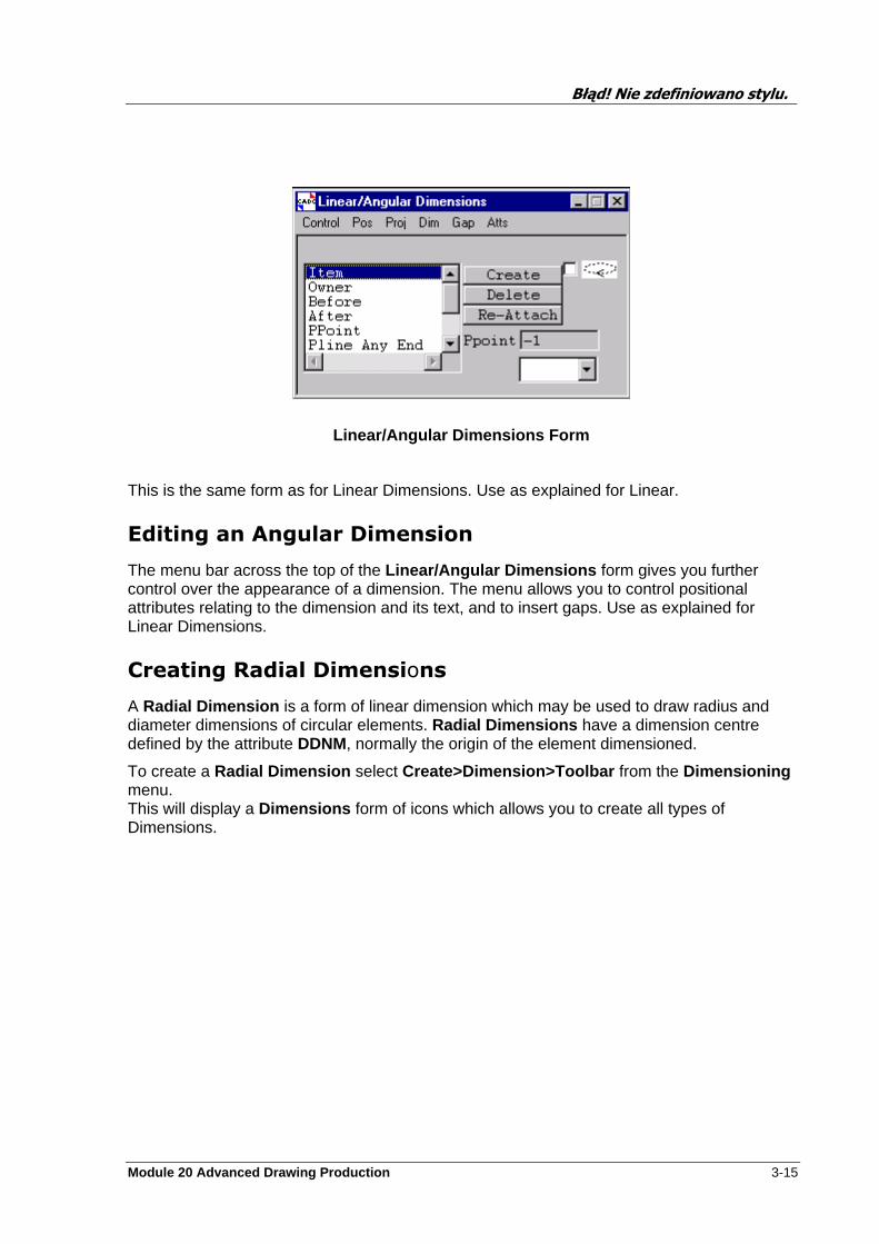
Błąd! Nie zdefiniowano stylu.
Module 20 Advanced Drawing Production 3-15
Linear/Angular Dimensions Form
This is the same form as for Linear Dimensions. Use as explained for Linear.
Editing an Angular Dimension
The menu bar across the top of the Linear/Angular Dimensions form gives you further control over the appearance of a dimension. The menu allows you to control positional attributes relating to the dimension and its text, and to insert gaps. Use as explained for Linear Dimensions.
Creating Radial Dimensions
A Radial Dimension is a form of linear dimension which may be used to draw radius and diameter dimensions of circular elements. Radial Dimensions have a dimension centre defined by the attribute DDNM, normally the origin of the element dimensioned.
To create a Radial Dimension select Create>Dimension>Toolbar from the Dimensioning menu. This will display a Dimensions form of icons which allows you to create all types of Dimensions.
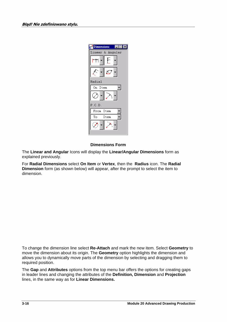
Błąd! Nie zdefiniowano stylu.
3-16 Module 20 Advanced Drawing Production
Dimensions Form
The Linear and Angular Icons will display the Linear/Angular Dimensions form as explained previously.
For Radial Dimensions select On Item or Vertex , then the Radius icon. The Radial Dimension form (as shown below) will appear, after the prompt to select the item to dimension.
To change the dimension line select Re-Attach and mark the new item. Select Geometry to move the dimension about its origin. The Geometry option highlights the dimension and allows you to dynamically move parts of the dimension by selecting and dragging them to required position.
The Gap and Attributes options from the top menu bar offers the options for creating gaps in leader lines and changing the attributes of the Definition, Dimension and Projection lines, in the same way as for Linear Dimensions.

Błąd! Nie zdefiniowano stylu.
Module 20 Advanced Drawing Production 3-17
For Diameters select On Item or Vertex , then the Diameter icon. The Diametral Dimension form (as shown below) will appear, after the prompt to select the item to dimension.
To change the dimension line select Re-Attach and mark the new item. Select Geometry to move the dimension about its origin.
The Gap and Attributes options from the top menu bar offers the options for creating gaps in leader lines and changing the attributes of the Definition, Dimension and Projection lines, in the same way as for Linear Dimensions.
The last form of Dimensioning is the Pitch Circle Diameter (PCD). This is a form of Radial dimension
From the Dimension Toolbar, choose From Item, From Ppoint, From Vertex, or From 3D Pos and pick the centre of the P.C.D. Then choose To Item, To Ppoint, To Vertex or To 3D Pos and select the item on the P.C.D. (This could be nozzles positioned around a Column). The following form will be displayed
Błąd! Nie zdefiniowano stylu.
3-18 Module 20 Advanced Drawing Production
All the options on this form are the same as for Radial dimensions, with the addition of the option Dim. This selection allows the user to change the angle of the dimension text to Standard, Horizontal, Vertical or Default.
Modifying Dimensioning Elements
All DRAFT dimensioning elements can be modified , starting from the Modify field on the DRAFT Dimensioning Menu . The procedure for modifying an element is very similar to that for creating it; refer to the preceding sections of this chapter for details of element creation.
Modifying Linear or Angular
Unless the Dimension you wish to modify is the current element, you must have a 2D View on display which includes the dimension.
Select the Modify pull down menu from the Dimensioning Menu. There are a number of actions available to you, Definition, Colour & Font, Dimension Line, Projection Line, Dimension Points, and Dimension Geometry.
Definition will display the Modify Linear or Angular or Radial/P.C.D. Dimension form. From this form you may change some of the dimension attributes like Text and Terminators.
Colour & Font will display the Dimension Colour & Font form that will allow you to change the text pen colour, the font size and style and the line style and colour for the selected Dimension.
Dimension Line will display the Dimension Attributes form that will allow you to change the text pen colour, the font size and style and the line style and colour for the selected Dimension.
Projection Line will display the Projection Attributes form that will allow you to change the text pen colour and the projection line colour, style and overshoot.
Dimension Points will display the Linear/Angular or Radial Dimension form depending which type dimension has been selected for modifying. From here you may Re-Attach the Dimension, add Gaps or change most attributes.
The last option, Modify>Dimension>Geometry is only applicable to Radial Dimensions. You will be prompted to select the Dimension requiring changes, the following form will appear.
Błąd! Nie zdefiniowano stylu.
Module 20 Advanced Drawing Production 3-19
The selected Dimension is highlighted with a pickable ’hot spot’. Change the Dimension by selecting the ’hot spot’ and moving it’s position.
Exercises
Note: The drawings created do not have to be the same as those in the example sheets found in Appendix C.
Create a sheet with a view and dimension it as shown by the example sheet 1.
Modify the dimensions created in Q 1 to now use the different Types , see example sheet 2.
Modify the view further but adding text to both the Dimension and Projection Lines.
Create a dimension that displays the true distance between selected items. Make sure that the items selected are not in line in either the X or Y directions of the sheet. See example sheet 3.
You have been asked to add some of the dimensions in both millimeters and imperial. Create two dimensions using imperial distances. See sheet 3 in appendix C. Hint: create a new Layer.

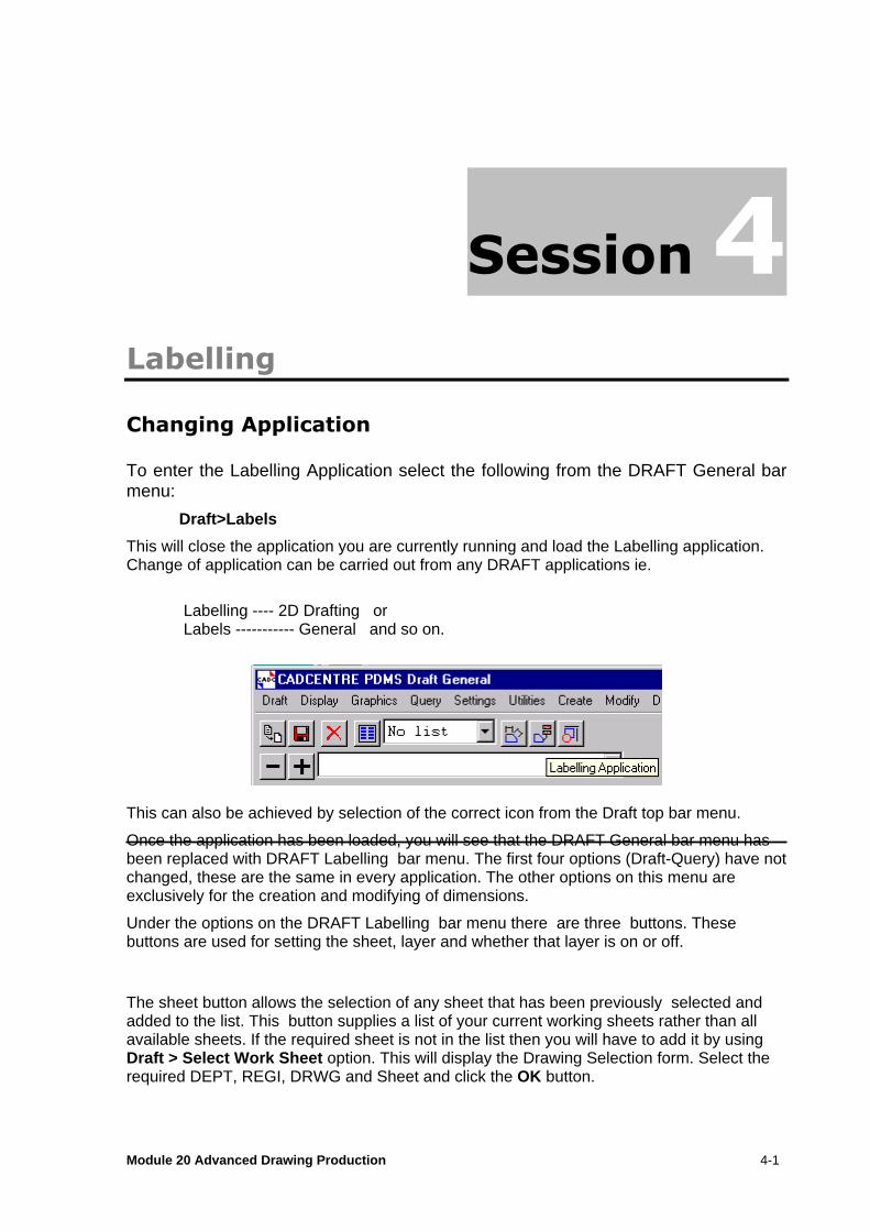
Module 20 Advanced Drawing Production 4-1
Labelling
Changing Application
To enter the Labelling Application select the following from the DRAFT General bar menu:
Draft>Labels
This will close the application you are currently running and load the Labelling application. Change of application can be carried out from any DRAFT applications ie.
Labelling ---- 2D Drafting or Labels ----------- General and so on.
This can also be achieved by selection of the correct icon from the Draft top bar menu.
Once the application has been loaded, you will see that the DRAFT General bar menu has been replaced with DRAFT Labelling bar menu. The first four options (Draft-Query) have not changed, these are the same in every application. The other options on this menu are exclusively for the creation and modifying of dimensions.
Under the options on the DRAFT Labelling bar menu there are three buttons. These buttons are used for setting the sheet, layer and whether that layer is on or off.
The sheet button allows the selection of any sheet that has been previously selected and added to the list. This button supplies a list of your current working sheets rather than all available sheets. If the required sheet is not in the list then you will have to add it by using Draft > Select Work Sheet option. This will display the Drawing Selection form. Select the required DEPT, REGI, DRWG and Sheet and click the OK button.

Błąd! Nie zdefiniowano stylu.
4-2 Module 20 Advanced Drawing Production
If the element required has been created since you first entered DRAFT or since your last update of this form, use the Re-load button in the top right hand corner of the form. This will Re-load the full Members List into this form. Having completed this select your required Sheet.
A sheet may also be added to the working sheet list by navigating to the element and selecting the plus key on the form main menus (shown above).
Selection of a sheet from the above from DRAFT main bar menu causes the selected sheet to be added to the Main Display.
The Layers button allows you to make all items held by that Layer to either invisible (OFF) or visible (ON).
The button positioned to the right of the ON/OFF button lists all the Layers which are currently owned by your current View who’s Purpose attribute is set to LAB or TAG or any other Purpose defined to be used for Labelling. Layers which have their PUR attribute set to something other than LAB or TAG or other defined Labelling Purpose will not be displayed in this application.
Note: Other Layer Purposes may be defined by the Draft Administrator for use with Labelling.
Introducing DRAFT Labelling
Labels are a form of drawing annotation, comprising text and/or graphics, associated with Design items. The Label elements are the General Label (GLAB), and the Symbolic Label (SLAB). SLABs are similar to GLABs except that they are generated from ‘templates’ (which can contain 2D primitives) defined by the Symbol Template (SYTM) element rather than simple text.
Label elements exist as members of Layers. SLAB templates (Symbol Templates and Text Templates , (TXTMs)) exist as members of Label Libraries (LALBs). The relevant part of the DRAFT database hierarchy is shown below.
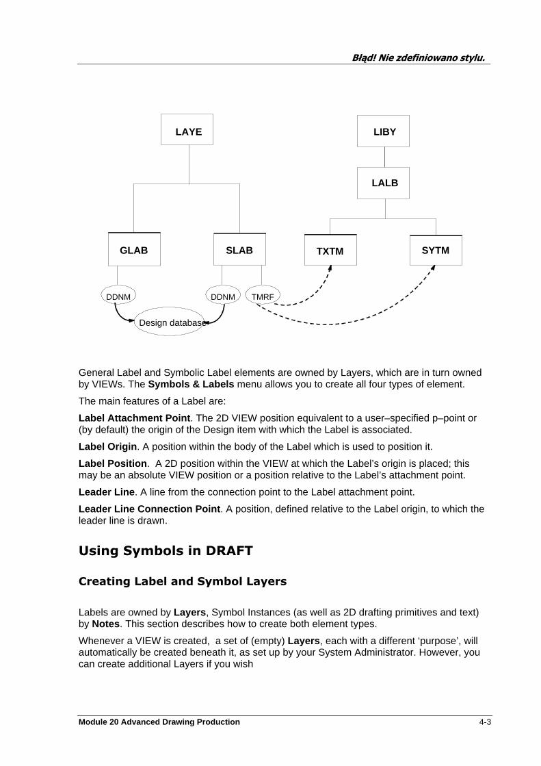
Błąd! Nie zdefiniowano stylu.
Module 20 Advanced Drawing Production 4-3
General Label and Symbolic Label elements are owned by Layers, which are in turn owned by VIEWs. The Symbols & Labels menu allows you to create all four types of element.
The main features of a Label are:
Label Attachment Point . The 2D VIEW position equivalent to a user–specified p–point or (by default) the origin of the Design item with which the Label is associated.
Label Origin . A position within the body of the Label which is used to position it.
Label Position . A 2D position within the VIEW at which the Label’s origin is placed; this may be an absolute VIEW position or a position relative to the Label’s attachment point.
Leader Line . A line from the connection point to the Label attachment point.
Leader Line Connection Point . A position, defined relative to the Label origin, to which the leader line is drawn.
Using Symbols in DRAFT
Creating Label and Symbol Layers
Labels are owned by Layers , Symbol Instances (as well as 2D drafting primitives and text) by Notes . This section describes how to create both element types.
Whenever a VIEW is created, a set of (empty) Layers , each with a different ‘purpose’, will automatically be created beneath it, as set up by your System Administrator. However, you can create additional Layers if you wish
TMRFDDNMDDNM
Design database
LAYE
GLAB SLAB
LIBY
TXTM SYTM
LALB
Błąd! Nie zdefiniowano stylu.
4-4 Module 20 Advanced Drawing Production
Starting at VIEW level, select Create>Layer . A Layer (LAYE) element will be created automatically, and a Create LAYE form will appear.
The Name text box will contain the automatically assigned Layer name, which you can change if you wish. Click on OK.
The Layer you have just created will appear in the Layer button, located on the Draft Labels bar menu, with its Purpose set to LAB, this is because you are using the Labels Application.
Layer Definition
To change any of the Layer Definition select Modify > Layer > Definition . If you wish to rename the Layer, backspace in the Name text box and type in the new name.
Should you wish to change the Layers Purpose then this may be carried out by selecting the Layer purpose using the Purpose option button. Choose whether the Layer is to be visible or not using the Visible option button. If you wish the Layer display attribute settings to be other than the defaults, click on the Attributes button. The Visibility can also be set from the Draft Labels bar menu.
Layer Attributes
A Layer Attributes form will be displayed, the particular type depending on the Purpose setting. Each Layer Attributes form allows those attributes relevant to the Layer’s purpose to be modified.
The Layer attribute settings which may be made from these forms will be used as the default settings (overidable at local level) for all elements which are subsequently created under the Layer.
For all the Layer Attributes forms, Line pen definitions (including those used for hatch patterns) may be set using the option buttons on the form, or may be chosen from a predefined set. (This set will probably have been set up by your system administrator to be standard for the project.)
Click on the appropriate User–Defined radio button, then click on the Reselect button. A Select User-Defined Pen form will appear. This form is identical to that available for use when creating Drawings.
Creating Labels
Labels may be General or Symbolic (or Special ). The two types are similar, except that Symbolic Labels reference graphic and/or text template information. Pipe End symbols may also be created from the same pull-down menu.
Creating a Symbolic Label
DRAFT is supplied with a comprehensive set of libraries of standard Symbolic Labels which can be picked and added to a drawing. (Your Draft Administrator may have changed the supplied Libraries to company–specific ones.) The Labels can include intelligent text so

Błąd! Nie zdefiniowano stylu.
Module 20 Advanced Drawing Production 4-5
that, for example, a Symbolic Label used on a Nozzle could display the Nozzle name and other information automatically.
A Symbolic Label can only be added to a Layer. To add a Symbolic Label you must have a 2D Area view on display which includes the relevant VIEW containing a Design element..
Select Create > Symbolic Label . from the Draft Labels bar menu. If necessary, identify the VIEW to which the Symbolic Label is to be added by acting on the message which appears. A Symbolic Labels form and a Library form will appear.
The Symbolic Labels form allows you to select the VIEW Layer that you wish the Labels to appear on. The process of picking a Symbolic Label, adding it to the VIEW, resizing it, moving it, manipulating its leader line and defining the element type it is to attach to are also controlled from this form.
The Library form is used to display the standard Symbolic Labels supplied with DRAFT. Different Libraries may be specified, each of which contains a selection of Label Libraries .
Use the Layer option button (on the Draft Labels bar menu) to specify the VIEW Layer that you wish the Labels to appear on. Only Layers with the purpose attribute set to LAB will be offered.
Select the element type that you wish to label from the Attach to option button. The default list consists of significant elements ; selecting Menu from the bottom of the list gives a list of non–significant element menus. Select Significant Elements to return to the original list.
The Library form will display those Symbolic Labels present in the Label Library whose name appears on the option button at the bottom of the form. If you don’t see the Label you want, change to a different Label Library (or to a different Library) using the option buttons at the bottom of the form. The display will update accordingly.
Click on Create NEW to initiate the Label picking/copying process.
NOTE: The text present with some of the Library Symbolic Labels may be descriptive only and not part of the Label itself.
Having initially positioned the Label on the VIEW, use the Scale and Rotate text boxes to adjust the size and orientation of the Label as necessary.
If you wish to change the attributes of the Symbolic Label click on the Attributes button. The Symbolic Label Attributes form will appear.
This form allows you to vary the text pen/font, leader line pen and terminators, and frame pen. These facilities are very similar to those used when creating (Label) Layers. This form also enables you vary the characteristics of the Label leader line . The same facilities are also available from the menu bar on the Symbolic Labels form itself.
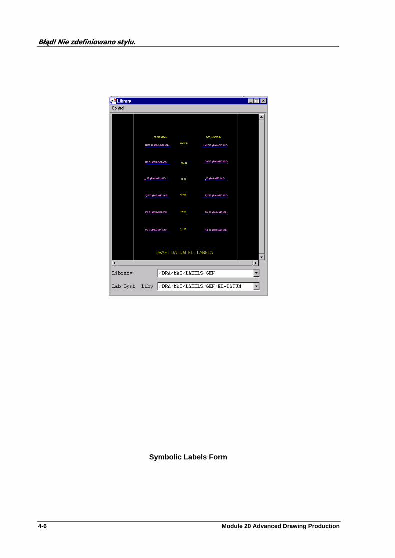
Błąd! Nie zdefiniowano stylu.
4-6 Module 20 Advanced Drawing Production
Symbolic Labels Form
Błąd! Nie zdefiniowano stylu.
Module 20 Advanced Drawing Production 4-7
Moving A Symbolic Label
Select Position>Label followed by Default, Cursor or Att.Point as required from the Symbolic Labels form.
Default will place the (origin of the) Label at its default position. This is at a fixed offset (X0 mm, Y0mm) from the Label’s attachment point . This default can be altered by the Draft Administrator.
Cursor will position the Label (origin) at the pointer position when the mouse button is clicked.
Att.Point will place the (origin of the) Label at its attachment point (i.e. there will be no leader line).
NOTE: Labels may also be moved using the Utils>Speed Position menu selection from the Symbols & Labels menu bar or Modify>Geometery (see later in this section).
Bending the Leader Line The Label leader line can be bent (or made straight) by using the Position>Bend menu selection on the Symbolic Labels form or by using the Leader>Bent (or Leader>Straight ) menu selections on the Symbolic Label Attributes form.
Make the appropriate menu selection (from either form) according to the leader line shape you wish to create. Each menu option refers to the shape of the leader line as it goes from the attachment point to the Label. A Leader Line Bend form will appear.
Each Leader Line Bend form contains a small diagram of the type of leader line bend being created.
Enter the required angle of bend. Note that a value must be supplied ; (unless the Cursor option is used, see below) there is no default value.
The position of the bend point is determined by the leader line shape selected and the angle of bend. If you wish to specify the bend point position, click on the Cursor button, then click with the pointer at the required bend point position. In this case the angle of bend will be calculated and displayed in the Angle box when Apply is clicked.
To create a totally ‘user–defined’ bent leader line (with neither horizontal nor vertical portions), select the Free (One Bend ) or Free (Two Bend ) option from the relevant menu.
Enter the required X,Y offsets, using the small diagram as an aid. Alternatively, click on the Cursor button, then click with the pointer at the required bend point position. In this case the X,Y offsets will be calculated and displayed in the Offset boxes when Apply is clicked.
NOTE: When manipulating the leader line from the Symbolic Labels form, click on Apply on the Leader Line Bend form to observe the change. When manipulating the leader line from the Symbolic Label Attributes form, click on Apply on the Leader Line Bend form, then click on Apply on the Symbolic Label Attributes form.
Błąd! Nie zdefiniowano stylu.
4-8 Module 20 Advanced Drawing Production
Straight Leader Lines
To straighten a bent leader line, select Position>Bend>Straight from the Symbolic Labels form or Leader>Straight from the Symbolic Label Attributes form, as appropriate.
Leader Line Clearance
Select Position>Clearance>Cursor from the Symbolic Labels form menu bar. Use the pointer to set the required leader line clearance.
The default leader line clearance is zero. To return to this state, select Position>Clearance>Default .
Leader Line Connection
Select Position>Connection Point from the Symbolic Labels form menu bar, or select Leader>Connection Point from the Symbolic Label Attributes form menu bar. A Connection Point form will appear.
Enter the required X,Y connection point offsets into the text boxes. Alternatively, click on the Cursor button, then click with the pointer at the required connection point position. In this case the X,Y offsets will be calculated and displayed in the X, Y boxes when OK is clicked.
The default connection point offset is zero (i.e. the connection point is coincident with the Label origin). To return to this state, click on the Default button.
Gaps in Leader Lines
Select Gap>Create>. . . from the Symbolic Labels form menu bar or Leader>Gap>Create> . . . from the Symbolic Label Attributes form menu bar. Note that a limit, which can not be altered, of maximum 10 gaps per projection line is in force. Selecting Default from the submenu and clicking on the leader line will produce a default–length gap (2mm) centred on the hit point, this value may be changed by the Draft Administrator as with all defaults. Selecting Start/Finish from the submenu allows you to create a gap by clicking on the required start and end points. Deletion of Gaps is achieved by selecting Gap>Delete> ... from the Symbolic Labels form menu bar or Leader>Gap>Delete> ... from the Symbolic Label Attributes form menu bar. Selecting Identify from the submenu requires you to click on the gap that you wish to delete, which will then be deleted. Selecting All deletes all leader line gaps from the currently selected Label.
Błąd! Nie zdefiniowano stylu.
Module 20 Advanced Drawing Production 4-9
Creating a General Label
To create a General Label you must have a 2D view on display that includes the VIEW within which you wish to create the Label along with the Design element that it is to be attached to. The VIEW Layer that you wish the Labels to appear on is selected from the Draft Labels bar menu.
Select Create>General>Label . If necessary, identify the VIEW to which the Symbolic Label is to be added by acting on the message that appears. A General Labels form will appear.
The processes of creating a Label, adding it to the VIEW, resizing it, moving it, manipulating its leader line and defining the element type it is to attach to are also controlled from this form.
Select the element type that you wish to label from the Attach to option button. The default list consists of significant elements ; selecting Menu from the bottom of the list gives a list of non–significant element menus. Select Significant Elements to return to the original list.
Click on Create NEW to initiate the Label picking/copying process. Many of the features of the Symbolic Labels form are common to the General Labels form.
If you wish to change the attributes of the Label, select from the Attributes option button the class of attributes that you wish to modify. Going down the list, Text Settings , Text Contents , Frame or Leader Line form will be displayed, as appropriate.
For Label text settings , the pen, font, justification and alignment are all selectable from the relevant option buttons on the Label Text Attributes form. The text character height, spacing and line spacing are set from the relevant text boxes.
For the Label frame , the frame visibility and pen can be selected from the relevant option buttons on the Label Frame Attributes form. The frame clearance and orientation are set from the relevant text boxes.
The Label leader line can be set to bent or straight via the Shape pull–down menu on the Label leader Attributes form. The available options are very similar to those available for Symbolic Labels. Leader line gaps are controllable from the Gap pull–down menu. The leader line pen and terminator type are selectable from the relevant option buttons, and the leader line clearance is set from the Clearance text box.
The Label text contents (i.e. intelligent text) are controlled by first selecting Text Contents from the Attributes option button. This gives the Label Contents form.
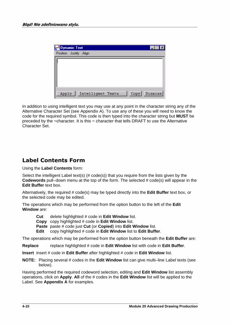
Błąd! Nie zdefiniowano stylu.
4-10 Module 20 Advanced Drawing Production
In addition to using intelligent text you may use at any point in the character string any of the Alternative Character Set (see Appendix A). To use any of these you will need to know the code for the required symbol. This code is then typed into the character string but MUST be preceded by the ~character. It is this ~ character that tells DRAFT to use the Alternative Character Set.
Label Contents Form
Using the Label Contents form:
Select the intelligent Label text(s) (# code(s)) that you require from the lists given by the Codewords pull–down menu at the top of the form. The selected # code(s) will appear in the Edit Buffer text box.
Alternatively, the required # code(s) may be typed directly into the Edit Buffer text box, or the selected code may be edited.
The operations which may be performed from the option button to the left of the Edit Window are:
Cut delete highlighted # code in Edit Window list. Copy copy highlighted # code in Edit Window list. Paste paste # code just Cut (or Copied ) into Edit Window list. Edit copy highlighted # code in Edit Window list to Edit Buffer .
The operations which may be performed from the option button beneath the Edit Buffer are:
Replace replace highlighted # code in Edit Window list with code in Edit Buffer .
Insert insert # code in Edit Buffer after highlighted # code in Edit Window list.
NOTE: Placing several # codes in the Edit Window list can give multi–line Label texts (see below).
Having performed the required codeword selection, editing and Edit Window list assembly operations, click on Apply . All of the # codes in the Edit Window list will be applied to the Label. See Appendix A for examples.
Błąd! Nie zdefiniowano stylu.
Module 20 Advanced Drawing Production 4-11
Moving a Label
Select Position>Label followed by Default , Cursor or Att.Point as required from the General Labels form.
Default will place the (origin of the) Label at its default position. This is at a fixed offset (X25 mm, Y25mm) from the Label’s attachment point .
Cursor will position the Label (origin) at the pointer position when the mouse button is clicked.
Att.Point will place the (origin of the) Label at its attachment point (i.e. there will be no leader line).
NOTE: Labels may also be moved using the Utils>Speed Position menu selection from the Symbols & Labels menu bar.
Bending the Leader Line
The Label leader line can be bent (or made straight) by using the Position>Bend menu selection on the General Labels form.
Make the appropriate menu selection according to the leader line shape you wish to create. A Leader Line Bend form will appear.
Each Leader Line Bend form contains a small diagram of the type of leader line bend being created.
Enter the required angle of bend. Note that a value must be supplied ; (unless the Cursor option is used, see below) there is no default value.
The position of the bend point is determined by the leader line shape selected and the angle of bend. If you wish to specify the bend point position, click on the Cursor button, then click with the pointer at the required bend point position. In this case the angle of bend will be calculated and displayed in the Angle box when Apply is clicked.
To create a totally ‘user–defined’ bent leader line (with neither horizontal nor vertical portions), select the Free(One Bend) or Free (Two Bends)? option from the Position>Bend menu selection.
Enter the required X,Y offsets, using the small diagram as an aid. Alternatively, click on the Cursor button, then click with the pointer at the required bend point position. In this case the X,Y offsets will be calculated and displayed in the Offset boxes when Apply is clicked.
Straight Leader Line
To straighten a bent leader line, select Position>Bend>Straight from the General Labels form.
Leader Line Clearance
Select Position>Clearance>Cursor from the General Labels form menu bar. Use the pointer to set the required leader line clearance.
The default leader line clearance is zero. To return to this state, select Position>Clearance>Default .
Gaps in Leader Line
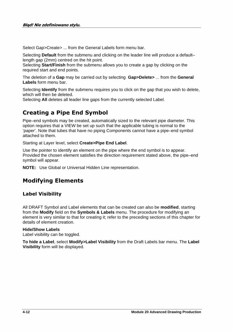
Błąd! Nie zdefiniowano stylu.
4-12 Module 20 Advanced Drawing Production
Select Gap>Create> ... from the General Labels form menu bar.
Selecting Default from the submenu and clicking on the leader line will produce a default–length gap (2mm) centred on the hit point. Selecting Start/Finish from the submenu allows you to create a gap by clicking on the required start and end points.
The deletion of a Gap may be carried out by selecting Gap>Delete> ... from the General Labels form menu bar.
Selecting Identify from the submenu requires you to click on the gap that you wish to delete, which will then be deleted. Selecting All deletes all leader line gaps from the currently selected Label.
Creating a Pipe End Symbol
Pipe–end symbols may be created, automatically sized to the relevant pipe diameter. This option requires that a VIEW be set up such that the applicable tubing is normal to the ‘paper’. Note that tubes that have no piping Components cannot have a pipe–end symbol attached to them.
Starting at Layer level, select Create>Pipe End Label .
Use the pointer to identify an element on the pipe where the end symbol is to appear. Provided the chosen element satisfies the direction requirement stated above, the pipe–end symbol will appear.
NOTE: Use Global or Universal Hidden Line representation.
Modifying Elements
Label Visibility
All DRAFT Symbol and Label elements that can be created can also be modified , starting from the Modify field on the Symbols & Labels menu. The procedure for modifying an element is very similar to that for creating it; refer to the preceding sections of this chapter for details of element creation.
Hide/Show Labels Label visibility can be toggled.
To hide a Label , select Modify>Label Visibility from the Draft Labels bar menu. The Label Visibility form will be displayed.
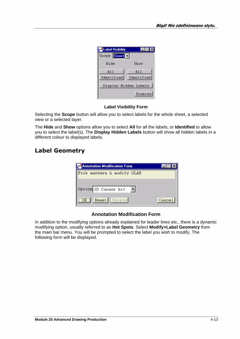
Błąd! Nie zdefiniowano stylu.
Module 20 Advanced Drawing Production 4-13
Label Visibility Form
Selecting the Scope button will allow you to select labels for the whole sheet, a selected view or a selected layer.
The Hide and Show options allow you to select All for all the labels, or Identified to allow you to select the label(s). The Display Hidden Labels button will show all hidden labels in a different colour to displayed labels.
Label Geometry
Annotation Modification Form
In addition to the modifying options already explained for leader lines etc., there is a dynamic modifying option, usually referred to as Hot Spots . Select Modify>Label Geometry from the main bar menu. You will be prompted to select the label you wish to modify. The following form will be displayed.
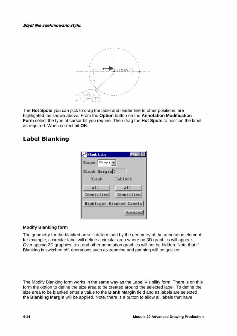
Błąd! Nie zdefiniowano stylu.
4-14 Module 20 Advanced Drawing Production
The Hot Spots you can pick to drag the label and leader line to other positions, are highlighted, as shown above. From the Option button on the Annotation Modification Form select the type of cursor hit you require. Then drag the Hot Spots to position the label as required. When correct hit OK.
Label Blanking
Modify Blanking form
The geometry for the blanked area is determined by the geometry of the annotation element: for example, a circular label will define a circular area where no 3D graphics will appear. Overlapping 2D graphics, text and other annotation graphics will not be hidden. Note that if Blanking is switched off, operations such as zooming and panning will be quicker.
The Modify Blanking form works in the same way as the Label Visibility form. There is on this form the option to define the size area to be created around the selected label. To define the size area to be blanked enter a value to the Blank Margin field and as labels are selected the Blanking Margin will be applied. Note, there is a button to allow all labels that have

Błąd! Nie zdefiniowano stylu.
Module 20 Advanced Drawing Production 4-15
already be blanked to be highlighted. As before this may be carried out on a sheet, view or layer bases.
Label Placement
Label Placement form
This facility helps to ‘tidy up’ crowded areas of labelling, minimising Label overlap and leader-line crossing. As well as changing label positions this facility may also be used to change Label orientations, text justification, alignments, and the definition of leader-line shapes.
Select
This block of controls allows you to select (Add) or deselect (Remove) Labels to be spread using a spreading list.
CE's Labels
Selects and individual Label (the current Label element) or all the Labels in the current VIEW or Layer.
Owner's Labels
Selects all the Labels of a Layer or VIEW.
ID Label
Allows a series of individual Labels to be picked.
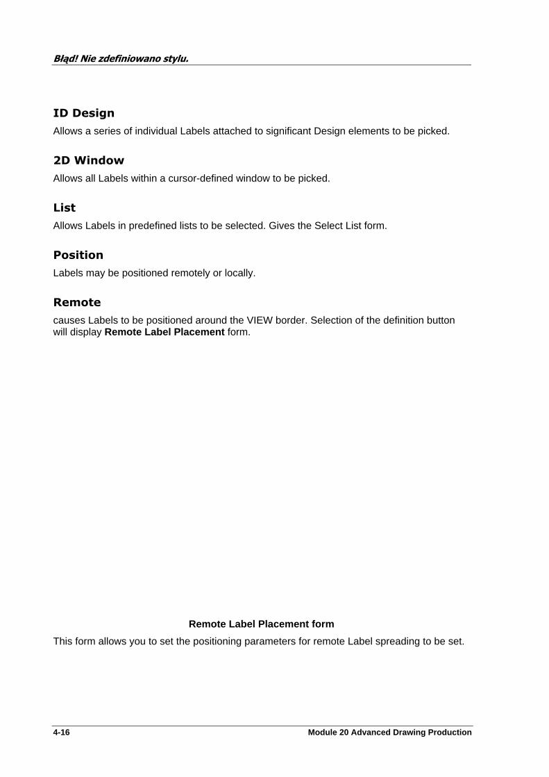
Błąd! Nie zdefiniowano stylu.
4-16 Module 20 Advanced Drawing Production
ID Design
Allows a series of individual Labels attached to significant Design elements to be picked.
2D Window
Allows all Labels within a cursor-defined window to be picked.
List
Allows Labels in predefined lists to be selected. Gives the Select List form.
Position
Labels may be positioned remotely or locally.
Remote
causes Labels to be positioned around the VIEW border. Selection of the definition button will display Remote Label Placement form.
Remote Label Placement form
This form allows you to set the positioning parameters for remote Label spreading to be set.
Błąd! Nie zdefiniowano stylu.
Module 20 Advanced Drawing Production 4-17
Region
The Labels may be spread around a rectangular region defined by the Cursor. The coordinates of the region will appear in the X Y boxes (from where they may be modified).
View Margin
The Labels may be spread around a given margin of the current VIEW boundary.
Use
By default, all four sides of the VIEW border will be used to spread the Labels along, but one or more sides may be omitted if required.
Automatic Orientation
Allows or suppresses automatic rotation of the Labels along the top and bottom sides of the VIEW border.
Local
Causes Labels to be positioned around their significant design elements.
Definition . . . enables you to define the spread parameters to be used, giving the Remote Label Replacement or Local Label Placement forms to be displayed, respectively. The Same option if selected will cause the entered value to be copied into the other window, eg. In the case below set X to 25 this will be copied to Y when the Enter button on the keyboard is used to confirm the setting. Selection of OK will have the same effect.
Local Label Placement form
The spread offset of the Labels from their attachment points can be specified directly using the X Offset, Y Offset boxes or indirectly using a Radius and an Angle.
Błąd! Nie zdefiniowano stylu.
4-18 Module 20 Advanced Drawing Production
Exercises
Note: The drawings created do not have to be the same as those in the example sheets found in Appendix D.
Create Labels for some of the equipment and nozzles show in the views used in the last exercise. If you wish see the example sheet 1 in appendix D.
Modify the Labels you created in Q. 1. to include extra textual information, change of character size, spacing. See example sheet 2.
Modify the Labels again to change the leader lines. Try the different options to achieve this. See example sheet 3.
Create a view which contains branch 150-A-57-B1 . View this from a suitable direction to allow the creation of a Pipe End Symbol . Add the required other Labels to show flow direction, the name of the branch, and the centre line elevation of the flange, elbow and pipe end. If you wish you may add others as well. See example sheet 4.
Module 20 Advanced Drawing Production 5-1
Autotagging
This section details the labelling and automatic symbol creation facilities given by Autotagging , which is activated by making the Draft>Labels>Create>Autotagging or Draft>Labels>Modify>Autotagging selection from the top bar menu.
NOTE: It is assumed for this section that the database Libraries containing standard Backing/Overlay Sheets , Representation Rules , Labels , Drawing Lists , Tag Rules , Circulation Lists and Symbols have been correctly installed. (Ask your System Administrator if you are not sure.)
It is further assumed that the Libraries supplied by CADCentre Ltd are being used. Your Draft Administrator may have installed Libraries specific to your company.
Autotagging
The ‘autotagging’ facility enables you to generate automatically a series of Labels in one or more VIEWS of a drawing Sheet, having defined a set of rules to control which elements are to be labelled and the (common) appearance of the labels.
The automatically generated Labels (which may be General or Symbolic) can then be individually edited. For example, it may be necessary to reposition a label or to modify its leader line. The editing functionality is subject to a few constraints so as to prevent Labels from becoming out of line with the criteria under which the autotagging process operated.
The ‘autotagging’ facility can be found under the Create or Modify options, on the Draft Labels bar menu.
The hierarchy for the creation of Tags is the same as for Lables. Tags will only be placed on Layers that have the Purp attribute set to TAG . The Draft Administrator can define other Purps that may be used in addition to TAG.
The TAGR shown in hierarchy below is a Tag Rule which can be defined locally by a user. Standard Tags Rules are available, these are created by the Draft Administrator. Note Labels created by Autotagging may not be deleted singularly. If the Tag Rule is deleted or Unset, in the case standard rules, then the labels will be removed.
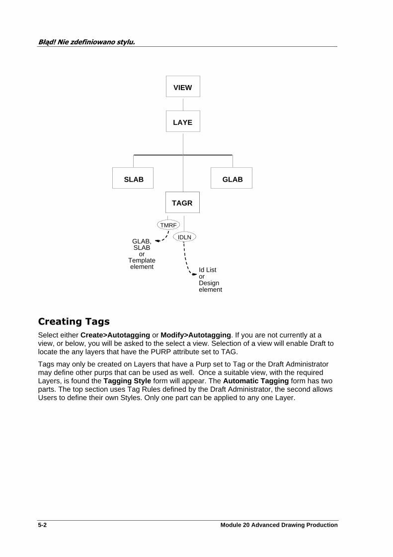
Błąd! Nie zdefiniowano stylu.
5-2 Module 20 Advanced Drawing Production
Creating Tags
Select either Create>Autotagging or Modify>Autotagging . If you are not currently at a view, or below, you will be asked to the select a view. Selection of a view will enable Draft to locate the any layers that have the PURP attribute set to TAG.
Tags may only be created on Layers that have a Purp set to Tag or the Draft Administrator may define other purps that can be used as well. Once a suitable view, with the required Layers, is found the Tagging Style form will appear. The Automatic Tagging form has two parts. The top section uses Tag Rules defined by the Draft Administrator, the second allows Users to define their own Styles. Only one part can be applied to any one Layer.
LAYE
SLAB
TAGR
VIEW
GLAB
TMRF
IDLN
Id List or Design element
GLAB,SLAB
orTemplateelement

Błąd! Nie zdefiniowano stylu.
Module 20 Advanced Drawing Production 5-3
Automatic Tagging form
Layer button lists all available Layers on which you may create GLABs & SLABs via Autotagging. Only Layers who’s purpose is ‘TAG’ will be listed here (by default only one such Layer will be present, although others may be created if required).
Defining Library Styles Choose from the Tag Rule Library option button the class of item that you wish to tag. The available options (and naming conventions) will have been set up by your Draft Administrator, but could include, for example, Equipment, Piping, Structures etc.
Choose from the Style option button the particular item type that you wish to tag. The available list will vary depending on the option selected from the Tag Rule Library list, the names in the list being those set up by your Draft Administrator.
Click on Apply (below Style ). A given TAG Layer may only contain one set of tags; defining a new set requires the existing set (if present) to be deleted; a message is displayed to this effect.
Defined by the Draft Administrator
User definable Rules and Labels
Available Layers
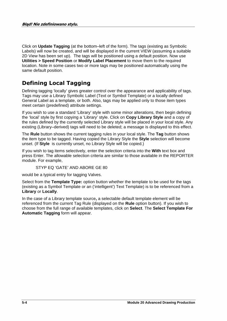
Błąd! Nie zdefiniowano stylu.
5-4 Module 20 Advanced Drawing Production
Click on Update Tagging (at the bottom–left of the form). The tags (existing as Symbolic Labels) will now be created, and will be displayed in the current VIEW (assuming a suitable 2D View has been set up). The tags will be positioned using a default position. Now use Utilities > Speed Position or Modify Label Placement to move them to the required location. Note in some cases two or more tags may be positioned automatically using the same default position.
Defining Local Tagging
Defining tagging ‘locally’ gives greater control over the appearance and applicability of tags. Tags may use a Library Symbolic Label (Text or Symbol Template) or a locally defined General Label as a template, or both. Also, tags may be applied only to those item types meet certain (predefined) attribute settings.
If you wish to use a standard ‘Library’ style with some minor alterations, then begin defining the ‘local’ style by first copying a ‘Library’ style. Click on Copy Library Style and a copy of the rules defined by the currently selected Library style will be placed in your local style. Any existing (Library–derived) tags will need to be deleted; a message is displayed to this effect.
The Rule button shows the current tagging rules in your local style. The Tag button shows the item type to be tagged. Having copied the Library Style the Style selection will become unset. (If Style is currently unset, no Library Style will be copied.)
If you wish to tag items selectively, enter the selection criteria into the With text box and press Enter. The allowable selection criteria are similar to those available in the REPORTER module. For example,
STYP EQ ’GATE’ AND ABORE GE 80
would be a typical entry for tagging Valves.
Select from the Template Type: option button whether the template to be used for the tags (existing as a Symbol Template or an (‘intelligent’) Text Template) is to be referenced from a Library or Locally .
In the case of a Library template source, a selectable default template element will be referenced from the current Tag Rule (displayed on the Rule option button). If you wish to choose from the full range of available templates, click on Select . The Select Template For Automatic Tagging form will appear.
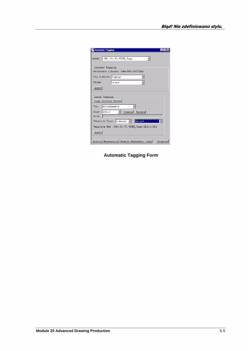
Błąd! Nie zdefiniowano stylu.
Module 20 Advanced Drawing Production 5-5
Automatic Tagging Form
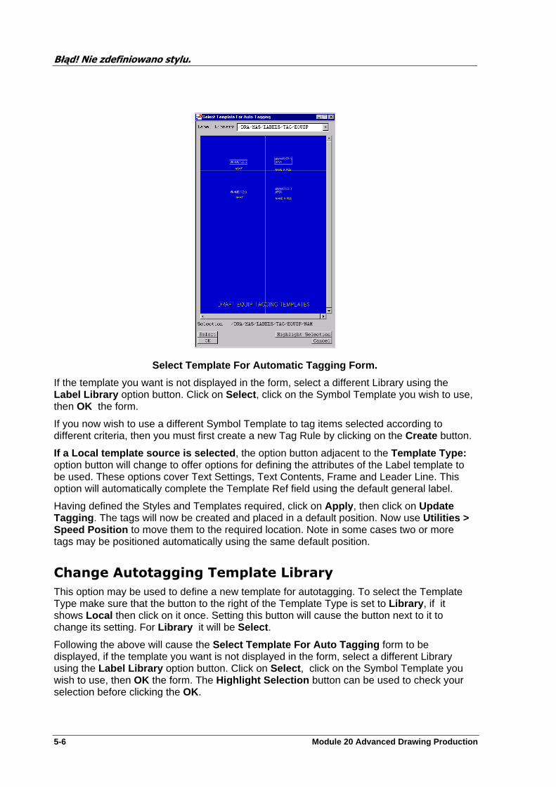
Błąd! Nie zdefiniowano stylu.
5-6 Module 20 Advanced Drawing Production
Select Template For Automatic Tagging Form.
If the template you want is not displayed in the form, select a different Library using the Label Library option button. Click on Select , click on the Symbol Template you wish to use, then OK the form.
If you now wish to use a different Symbol Template to tag items selected according to different criteria, then you must first create a new Tag Rule by clicking on the Create button.
If a Local template source is selected , the option button adjacent to the Template Type: option button will change to offer options for defining the attributes of the Label template to be used. These options cover Text Settings, Text Contents, Frame and Leader Line. This option will automatically complete the Template Ref field using the default general label.
Having defined the Styles and Templates required, click on Apply , then click on Update Tagging . The tags will now be created and placed in a default position. Now use Utilities > Speed Position to move them to the required location. Note in some cases two or more tags may be positioned automatically using the same default position.
Change Autotagging Template Library
This option may be used to define a new template for autotagging. To select the Template Type make sure that the button to the right of the Template Type is set to Library , if it shows Local then click on it once. Setting this button will cause the button next to it to change its setting. For Library it will be Select .
Following the above will cause the Select Template For Auto Tagging form to be displayed, if the template you want is not displayed in the form, select a different Library using the Label Library option button. Click on Select , click on the Symbol Template you wish to use, then OK the form. The Highlight Selection button can be used to check your selection before clicking the OK.
Błąd! Nie zdefiniowano stylu.
Module 20 Advanced Drawing Production 5-7
Your selected template’s name will be transferred to Tagging Style form and displayed following the Template Ref option. If you click the Apply without setting this field, a warning will be displayed to inform you that this is unset.
Błąd! Nie zdefiniowano stylu.
5-8 Module 20 Advanced Drawing Production
Exercise
Note: The drawings created do not have to be the same as those in the example sheets found in Appendix D.
Create Labels using Autotagging for all the nozzles on the layout drawing for the Stabilizer Equipment and reposition them.
Create a new Tag Layer and switch the visibility of the Layer used in Q 1 off.
Tag all equipment with its name and position. Reposition tags if required, using speed position
Tag only the nozzles that have a CATREF equal to
/ANSI-FLANGED/AAZFBD0TT.
Tag nozzles which belong to equipment /1101 then using
Modify>Label Placement place the around the equipment.
Hint try local change angle.
Try the remote positioning
Hint: try sending them to the Top set the View Margin to negative number.
Module 20 Advanced Drawing Production 6-1
Section Planes
DRAFT gives you the ability to construct sections through specified Design items, the results of which can be displayed at VIEW level. All Planes are database items and can therefore be used with more than one VIEW. Three types of section plane can be defined although one type has two variations.
The Section Mode option button, on View Create or Modify, can be set to Omit Fractional Components, in which case, any components which are not completely inside the sectioned View will be omitted.
The creation of sections is carried out from the General Application of Draft. If you are not already in the General Application change to this using Draft>General. Note there is no icon to do this, although the creation and modification can be carried out via the Utilities>General Toolbar if displayed.
Perpendicular Flat Plane
This type passes through a specified point in the 3D design, being oriented so as to be perpendicular to the current VIEW direction. The VIEW contents, which will be discarded, can be on either side of the plane. This type of plane would be used as either a section or a backing plane.
Flat Plane
This is similar to the perpendicular flat plane, but can be oriented to allow views of the section from any angle.
Stepped Plane
This type may have the plane defined either as OPEN or CLOSED. Both of these are created and used in the same way, the difference being that the lines used to define the plane must never cross (OPEN) or the start and finish point must be the same (CLOSED).
OPEN
This is a folded plane (i.e. a series of non–intersecting straight line spans) that extends to infinity in both directions along a specified axis. The shape is defined by a series of points, the ends of the plane also extending to infinity. The simplest form of stepped plane would be
Błąd! Nie zdefiniowano stylu.
6-2 Module 20 Advanced Drawing Production
defined by two points and would be equivalent to a Flat Plane. Any VIEW direction can be used and the VIEW contents on either side can be discarded. Note that the two end spans must not intersect each other or an inner span.
Closed or Enclosed Plane
This is a particular form of stepped plane in which the first and last points that define it coincide to form a ‘tube’ which is infinitely long along its axis. Any VIEW direction can be used and either the inside or outside of the ‘tube’ can be removed.
All Planes are created and held within a Library structure, and are owned by a Planes Library (PLLB). To use a plane to produce a sectioned view of part of the Design, you need to create a View Section (VSEC) element (starting at the relevant VIEW), which will refer to the appropriate type of plane element in the Planes Library.
A Planes Library is always created automatically (if the Drawing does not already have one) whenever you make one of the Create>View>Section menu selections. The appropriate type of Plane is then created as a member of the Planes Library, being referred to by the VIEW Section.
NOTE: Sectioning will only be displayed for non– simple wireline VIEWs.
Flat Plane
Starting at VIEW level, select Create>View>Section Flat. A View Section element will be created automatically, and a Create a Flat Plane form will appear.
Create Flat Plane Form
The Name text box will contain the automatically assigned Plane name, which you can change if you wish.
Select the required Plane positioning method from the option button located to the right of the Position button, then click on the Position button. Position the 3D point through which the plane is to pass.

Błąd! Nie zdefiniowano stylu.
Module 20 Advanced Drawing Production 6-3
If Explicit is selected, an Explicit Plane Position form will appear. Enter the required co-ordinates into the text boxes and click on Apply .
If Id Cursor , Id P-Point or Cursor is selected, an appropriate message will be displayed. Click on the required Design item, p–point (wireline views only) or 3D–point as appropriate.
Cutting option button lists the available Drawlists. The items to be cut by the plane will be those referred to by the selected list. If World is selected, all items in the owning VIEW’s Drawlist will be cut.
Direction defines a vector normal to the plane, set to the current VIEW direction by default. If you wish to change this, type the new direction into the text box.
Centerline Mode . If this is active then everything included on the Drawlist except the Center-Line of pipes if displayed will be Cut .
Retain Data option button lists the available options for defining which side of the cut items are to be discarded from the display. The default In front of Plane means that everything on the observer’s side of the plane will be discarded. Select as appropriate.
Having clicked on OK, select Graphics>Update>Design from the Draft General bar menu in order to update the VIEW contents.
Perpendicular Plane
Starting at VIEW level, select Create>View>Section Perpendicular . A View Section element will be created automatically , and a Create a Perpendicular Plane form will appear.
Create Perpendicular Plane Form
The Name text box will contain the automatically assigned Plane name, which you can change if you wish.
Select the required Plane positioning method from the option button located to the right of the Position button, then click on the Position button. Position the 3D point through which the plane is to pass.
Błąd! Nie zdefiniowano stylu.
6-4 Module 20 Advanced Drawing Production
If Explicit is selected, an Explicit Plane Position form will appear. Enter the required co-ordinates into the text boxes and click on Apply .
If Id Cursor , Id P-Point or Cursor is selected, an appropriate message will be displayed. Click on the required Design item, p–point (wireline views only) or 3D–point as appropriate.
The Cutting option button lists the available Drawlists. The items to be cut by the plane will be those referred to by the selected list. If World is selected, all items in the owning VIEW’s Drawlist will be cut.
NOTE: You can only input a 3D Design position on orthogonal VIEWs; the looking direction of such a VIEW will determine which co-ordinate is returned as zero. For example, a plan view will return U0 which you may need to alter to give the required section.
Centreline Mode . If this is active then everything included on the Drawlist except the Centreline of pipes if displayed will be Cut .
Retain Data option button lists the available options for defining which side of the cut items are to be discarded from the display. The default In front of Plane means that everything on the observer’s side of the plane will be discarded. Select as appropriate.
Having clicked on OK, select Graphics>Update>Design from the Draft General bar menu in order to update the VIEW contents.
Stepped Plane
Starting at VIEW level, select Create>View>Section Stepped?.?.?. . A View Section (VSEC) element will be created automatically, and a Create a Stepped Plane form will appear.
Create Stepped Plane Form

Błąd! Nie zdefiniowano stylu.
Module 20 Advanced Drawing Production 6-5
The Name text box will contain the automatically assigned Plane name, which you can change if you wish.
Select the plane’s extrusion direction using the Direction option button.
Press the Show Scrap View button. This shows a small view of the VIEW (in simple wireline representation), looking in the extrusion direction.
NOTE: A scrap view is not necessary if the VIEW’s looking direction and the plane’s extrusion direction are the same (or at 180° to eac h other).
The Cutting option button lists the available Drawlists. The items to be cut by the plane will be those referred to by the selected list. If World is selected, all items in the owning VIEW’s Drawlist will be cut.
The Retain Data option button lists the available options for defining which side of the cut items are to be discarded from the display. The default In front of Plane means that everything on the observer’s side of the plane will be discarded. Select as appropriate.
The Type option button controls whether the Plane is to be ‘open’ or ‘closed’ - select as appropriate.
The Sketch button, when selected, will draw the profile of the cutting plane being used. Selection of the Erase Button will remove from the screen the drawing aids showing the cutting plane.
Select the required step point positioning method from the Using option button, followed by the required point creation method.
The Create Point and Auto buttons are used to create the step points. Create Point creates a single point, Auto creates a sequence of points until the associated message alert is cancelled.
If Explicit is selected, an Explicit Point Position form will appear. Enter the required co-ordinates into the text boxes and click on Apply .
If Id Cursor , Id P-Point or Cursor or Cursor Orth. is selected, an appropriate message will be displayed. Click on the required Design item, p–point (simple wireline views only) or 2D–point as appropriate.
Cursor Orth. gives a sequence of plane ‘folds’ which are always at 90° to each other; the step positions need only be approximate.
The step points are positioned using the scrap view (or in the ‘main’ view if no scrap view has been generated). As each point is entered, the resulting plane will be ‘sketched’. The retained graphics will lie outside of the shaded area when the retained data is in front of the plane, vice versa if the retained data is behind the plane.
Create step points, using the chosen method as many times as necessary to define the stepped plane.
Having clicked on OK, select Graphics>Update>Design from the System menu in order to update the VIEW contents.
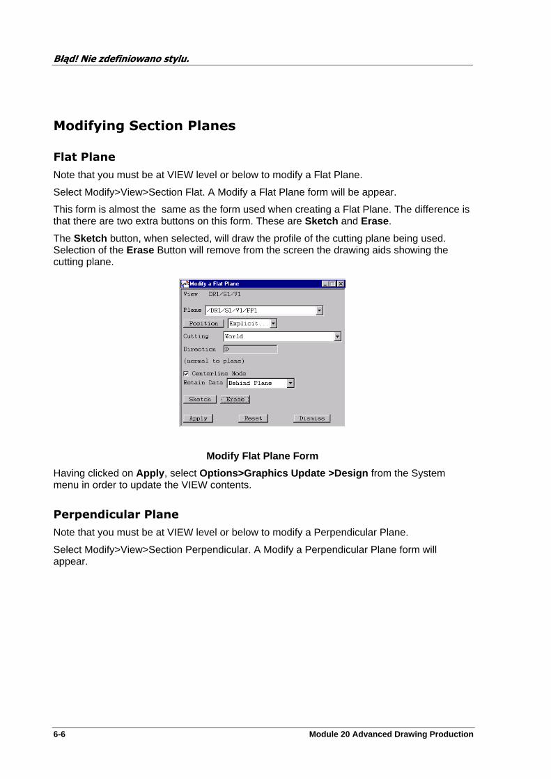
Błąd! Nie zdefiniowano stylu.
6-6 Module 20 Advanced Drawing Production
Modifying Section Planes
Flat Plane
Note that you must be at VIEW level or below to modify a Flat Plane.
Select Modify>View>Section Flat. A Modify a Flat Plane form will be appear.
This form is almost the same as the form used when creating a Flat Plane. The difference is that there are two extra buttons on this form. These are Sketch and Erase .
The Sketch button, when selected, will draw the profile of the cutting plane being used. Selection of the Erase Button will remove from the screen the drawing aids showing the cutting plane.
Modify Flat Plane Form
Having clicked on Apply , select Options>Graphics Update >Design from the System menu in order to update the VIEW contents.
Perpendicular Plane
Note that you must be at VIEW level or below to modify a Perpendicular Plane.
Select Modify>View>Section Perpendicular. A Modify a Perpendicular Plane form will appear.

Błąd! Nie zdefiniowano stylu.
Module 20 Advanced Drawing Production 6-7
Modify Perpendicular Plane Form
Having clicked on Apply , select Graphics>Update >Design from the System menu in order to update the VIEW contents.
Stepped Plane
Note that you must be at VIEW level or below to modify a Stepped Plane.
Select Modify>View>Section Stepped. A Modify a Stepped Plane form will appear.
Select the Plane to be modified from the list given by the Plane option button.
At this point it is useful to produce a scrap view of the plane and the sectioned items. Click on Show Scrap View , then click on Sketch . The step points appear as small circles.
The Cutting option button lists the available Drawlists. The items to be cut by the plane will be those referred to by the selected list. If World is selected, all items in the VIEW’s Drawlist will be cut.
The Retain Data option button lists the available options for defining which side of the cut items are to be discarded from the display. The default In front of Plane means that everything on the observer’s side of the plane will be discarded. Select as appropriate.
The Type option button controls whether the Plane is to be ‘open’ or ‘closed’ - select as appropriate.
If you wish to create a new point , select the required step point positioning method from the Using option button, followed by the required point creation method.
The procedure at this point is the same as when creating a new point.
If you wish to modify an existing point , select the required step point from the Point option button. The procedure is then the same as when creating a new point.
If you wish to delete an existing point , select the required step point from the Point option button, then click on the Delete button.
If you wish to remove the plane sketch, click on Erase . (Click on Sketch to restore the sketch.)
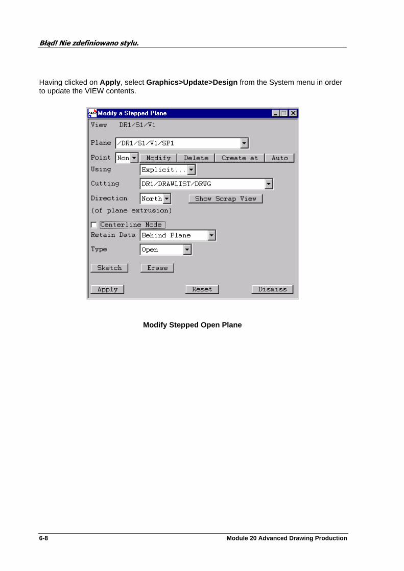
Błąd! Nie zdefiniowano stylu.
6-8 Module 20 Advanced Drawing Production
Having clicked on Apply , select Graphics>Update>Design from the System menu in order to update the VIEW contents.
Modify Stepped Open Plane
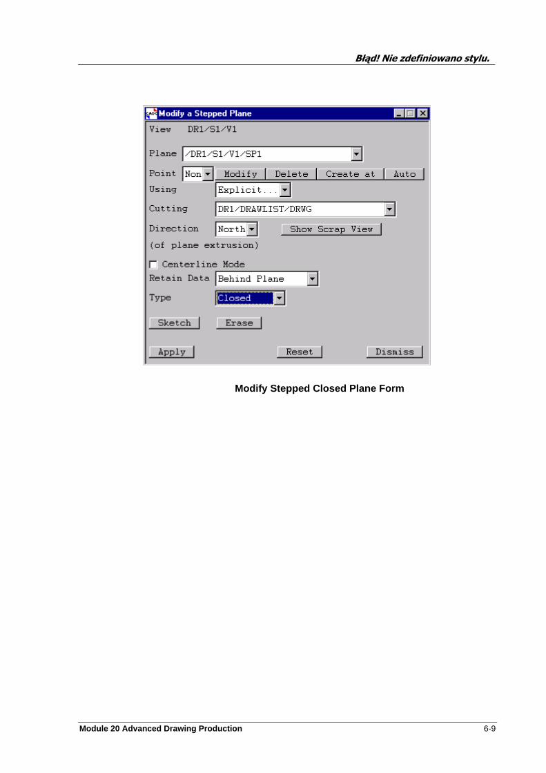
Błąd! Nie zdefiniowano stylu.
Module 20 Advanced Drawing Production 6-9
Modify Stepped Closed Plane Form
Błąd! Nie zdefiniowano stylu.
6-10 Module 20 Advanced Drawing Production
Exercise
Note: The drawings created do not have to be the same as those in the example sheets found in Appendix E.
Create a sheet of any size which contains four views. In each of the views create a section that shows the pump 1501A and the WALLSITE element.
These sections may be created using any or all of the planes available.
Create another sheet with a view and create any section that you wish. You may use as many planes as you wish to give the required result.
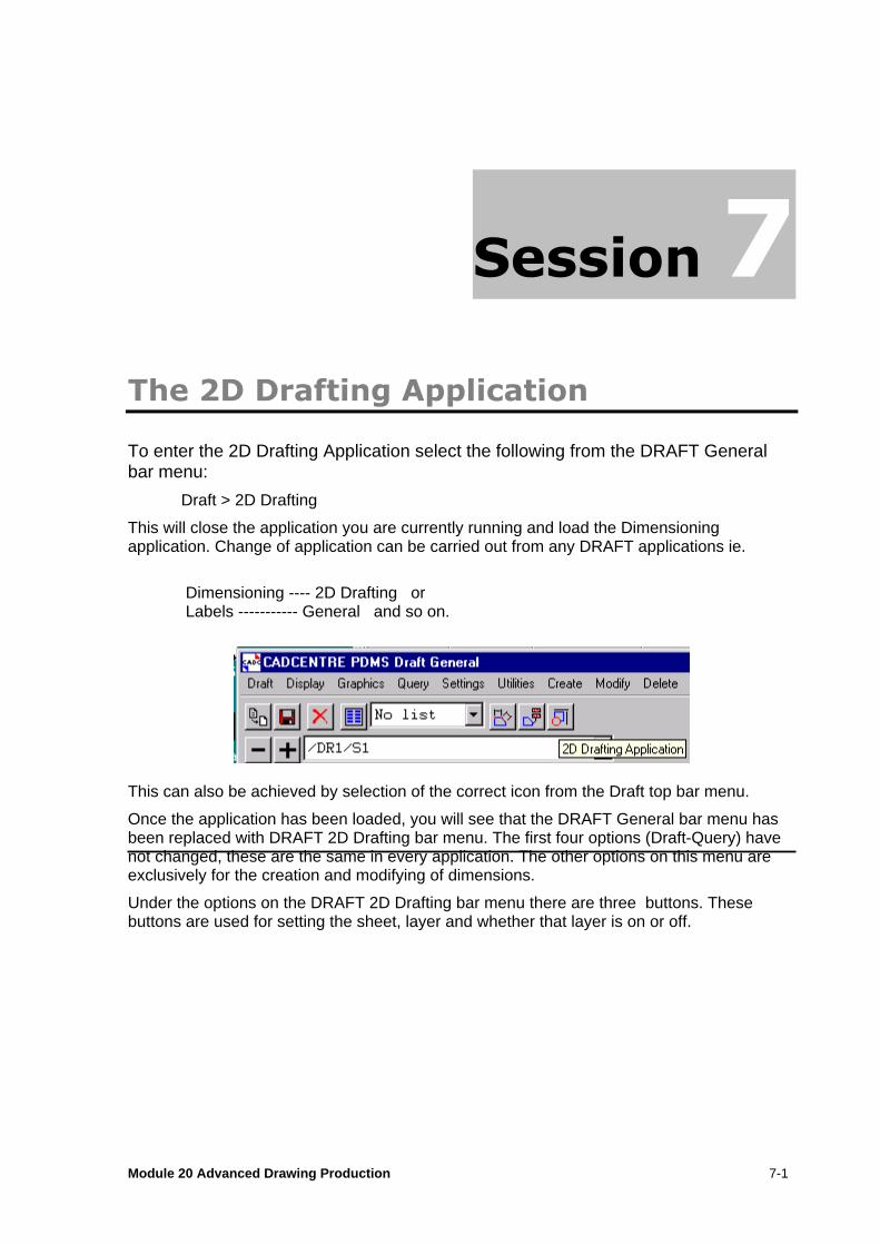
Module 20 Advanced Drawing Production 7-1
The 2D Drafting Application
To enter the 2D Drafting Application select the following from the DRAFT General bar menu:
Draft > 2D Drafting
This will close the application you are currently running and load the Dimensioning application. Change of application can be carried out from any DRAFT applications ie.
Dimensioning ---- 2D Drafting or Labels ----------- General and so on.
This can also be achieved by selection of the correct icon from the Draft top bar menu.
Once the application has been loaded, you will see that the DRAFT General bar menu has been replaced with DRAFT 2D Drafting bar menu. The first four options (Draft-Query) have not changed, these are the same in every application. The other options on this menu are exclusively for the creation and modifying of dimensions.
Under the options on the DRAFT 2D Drafting bar menu there are three buttons. These buttons are used for setting the sheet, layer and whether that layer is on or off.
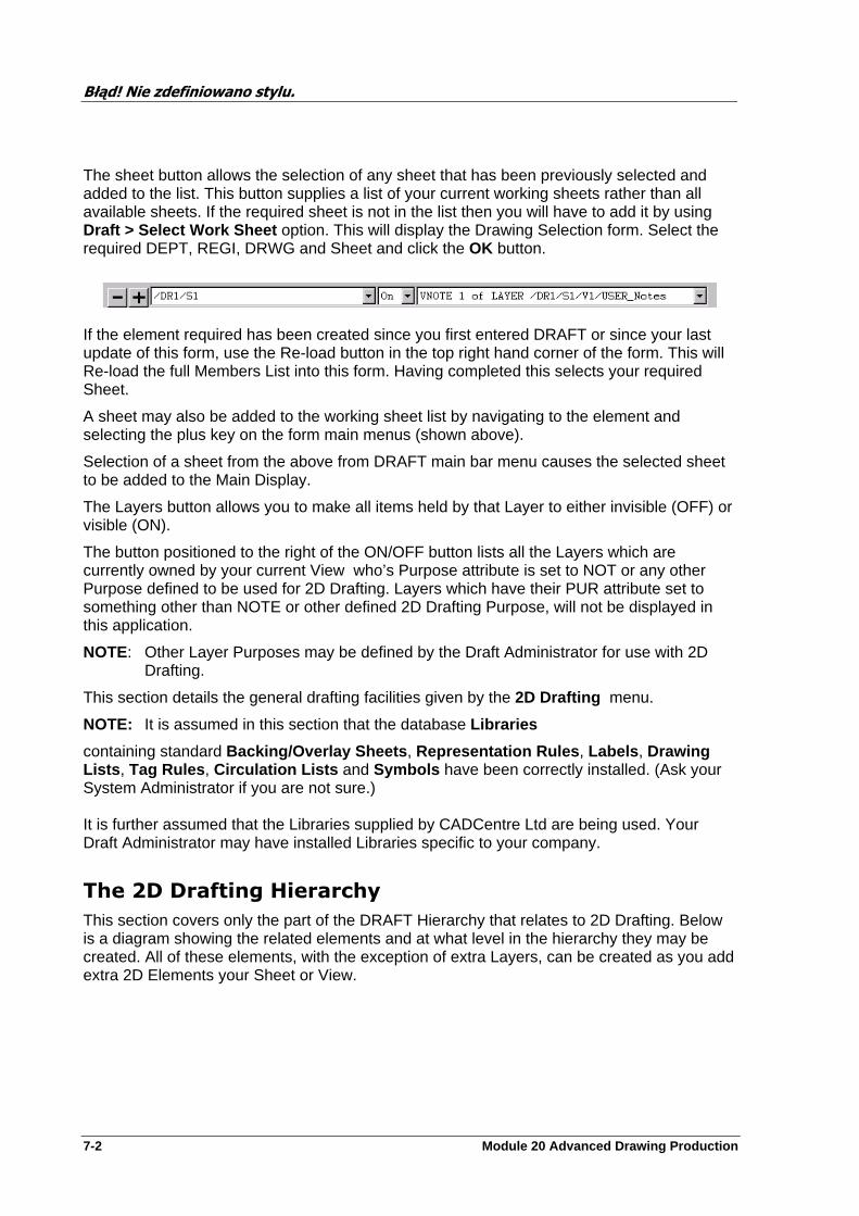
Błąd! Nie zdefiniowano stylu.
7-2 Module 20 Advanced Drawing Production
The sheet button allows the selection of any sheet that has been previously selected and added to the list. This button supplies a list of your current working sheets rather than all available sheets. If the required sheet is not in the list then you will have to add it by using Draft > Select Work Sheet option. This will display the Drawing Selection form. Select the required DEPT, REGI, DRWG and Sheet and click the OK button.
If the element required has been created since you first entered DRAFT or since your last update of this form, use the Re-load button in the top right hand corner of the form. This will Re-load the full Members List into this form. Having completed this selects your required Sheet.
A sheet may also be added to the working sheet list by navigating to the element and selecting the plus key on the form main menus (shown above).
Selection of a sheet from the above from DRAFT main bar menu causes the selected sheet to be added to the Main Display.
The Layers button allows you to make all items held by that Layer to either invisible (OFF) or visible (ON).
The button positioned to the right of the ON/OFF button lists all the Layers which are currently owned by your current View who’s Purpose attribute is set to NOT or any other Purpose defined to be used for 2D Drafting. Layers which have their PUR attribute set to something other than NOTE or other defined 2D Drafting Purpose, will not be displayed in this application.
NOTE: Other Layer Purposes may be defined by the Draft Administrator for use with 2D Drafting.
This section details the general drafting facilities given by the 2D Drafting menu.
NOTE: It is assumed in this section that the database Libraries
containing standard Backing/Overlay Sheets , Representation Rules , Labels , Drawing Lists , Tag Rules , Circulation Lists and Symbols have been correctly installed. (Ask your System Administrator if you are not sure.) It is further assumed that the Libraries supplied by CADCentre Ltd are being used. Your Draft Administrator may have installed Libraries specific to your company.
The 2D Drafting Hierarchy
This section covers only the part of the DRAFT Hierarchy that relates to 2D Drafting. Below is a diagram showing the related elements and at what level in the hierarchy they may be created. All of these elements, with the exception of extra Layers, can be created as you add extra 2D Elements your Sheet or View.

Błąd! Nie zdefiniowano stylu.
Module 20 Advanced Drawing Production 7-3
Creating 2D Drafting Base Elements
2D Drafting primitives can only exist as members of Sheet Notes (NOTE elements) or Layer Notes (VNOT) elements. By default, these elements will be created automatically whenever a Sheet or Layer element is created, but you can create additional ones if you wish.
Whenever a VIEW is created, a number of Layers (each with a different ‘purpose’) are automatically created, but you can create additional Layers if you wish via the Create>Layer from the Draft 2D Drafting bar menu. The creation and modification of Layer is carried out as with other applications.
Selection of a particular Sheet or Layer Note is from the Draft 2D Drafting bar menu, as is the setting of visibility.
Creation of Notes
Notes (for use by 2D drafting, text and symbol elements) may be created at Sheet (Sheet Note) or Layer (Layer Note) level.
To create a Note, simply navigate to the appropriate element and select Create>Note . A Sheet Note (NOTE element) or a Layer Note (VNOT element) will be created, as
SHEE
VIEW
LAYE
VNOT
NOTE
:
SYMBTEXPCIRCELLIRECTTABLETRIDMNDHEXAMRKPSTRAARCOUTL
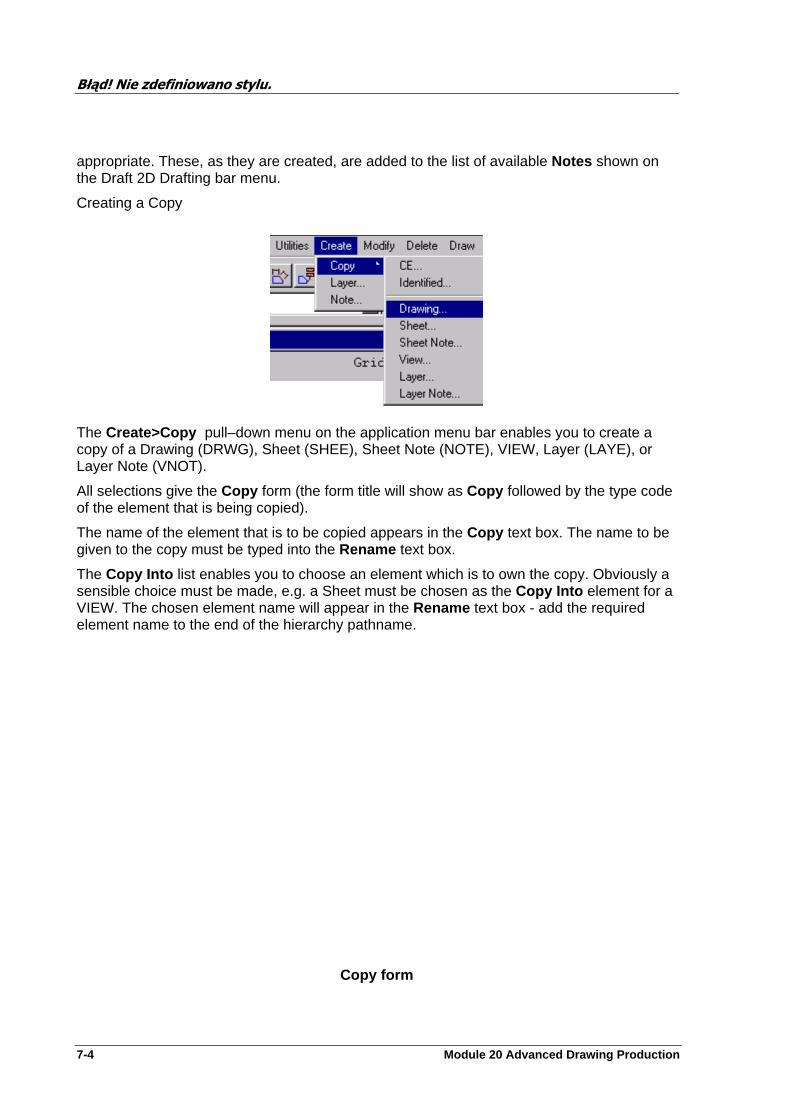
Błąd! Nie zdefiniowano stylu.
7-4 Module 20 Advanced Drawing Production
appropriate. These, as they are created, are added to the list of available Notes shown on the Draft 2D Drafting bar menu.
Creating a Copy
The Create>Copy pull–down menu on the application menu bar enables you to create a copy of a Drawing (DRWG), Sheet (SHEE), Sheet Note (NOTE), VIEW, Layer (LAYE), or Layer Note (VNOT).
All selections give the Copy form (the form title will show as Copy followed by the type code of the element that is being copied).
The name of the element that is to be copied appears in the Copy text box. The name to be given to the copy must be typed into the Rename text box.
The Copy Into list enables you to choose an element which is to own the copy. Obviously a sensible choice must be made, e.g. a Sheet must be chosen as the Copy Into element for a VIEW. The chosen element name will appear in the Rename text box - add the required element name to the end of the hierarchy pathname.
Copy form
Błąd! Nie zdefiniowano stylu.
Module 20 Advanced Drawing Production 7-5
Drawing - copies a Drawing (DRWG). An element owned by the DRWG may be chosen. The Copy facility will automatically navigate upwards to the DRWG.
Sheet - copies a Sheet (SHEE). If the current element is above the relevant SHEE in the hierarchy, an element owned by the SHEE must be cursor–identified. If the current element is below the relevant SHEE in the hierarchy, the Copy facility will automatically navigate upwards to the SHEE.
Sheet Note - copies a Note (NOTE). If the current element is above the relevant Note in the hierarchy, an element owned by the Note must be cursor–identified. If the current element is below the relevant Note in the hierarchy, the Copy facility will automatically navigate upwards to the NOTE.
View - copies a VIEW. If the current element is above the relevant VIEW in the hierarchy, an element owned by the VIEW, or the VIEW itself, must be cursor–identified. If the current element is below the relevant VIEW in the hierarchy, the Copy facility will automatically navigate upwards to the VIEW.
Layer - copies a Layer (LAYE). If the current element is above the relevant LAYE in the hierarchy, an element owned by the LAYE must be cursor–identified. If the current element is below the relevant LAYE in the hierarchy, the Copy facility will automatically navigate upwards to the LAYE.
Layer Note - copies a Layer Note (VNOT). If the current element is above the relevant VNOT in the hierarchy, an element owned by the VNOT must be cursor–identified. If the current element is below the relevant VNOT in the hierarchy, the Copy facility will automatically navigate upwards to the VIEW.
Modifying 2D Drafting Base Elements
All 2D Drafting base elements which can be created can also be modified , starting from the Modify field on the 2D Drafting menu. The procedure for modifying an element is very similar to that for creating it; refer to the preceding section for details of element creation.
It is assumed that since the modification of these elements is the same as in other chapters, there is no need to cover this again.
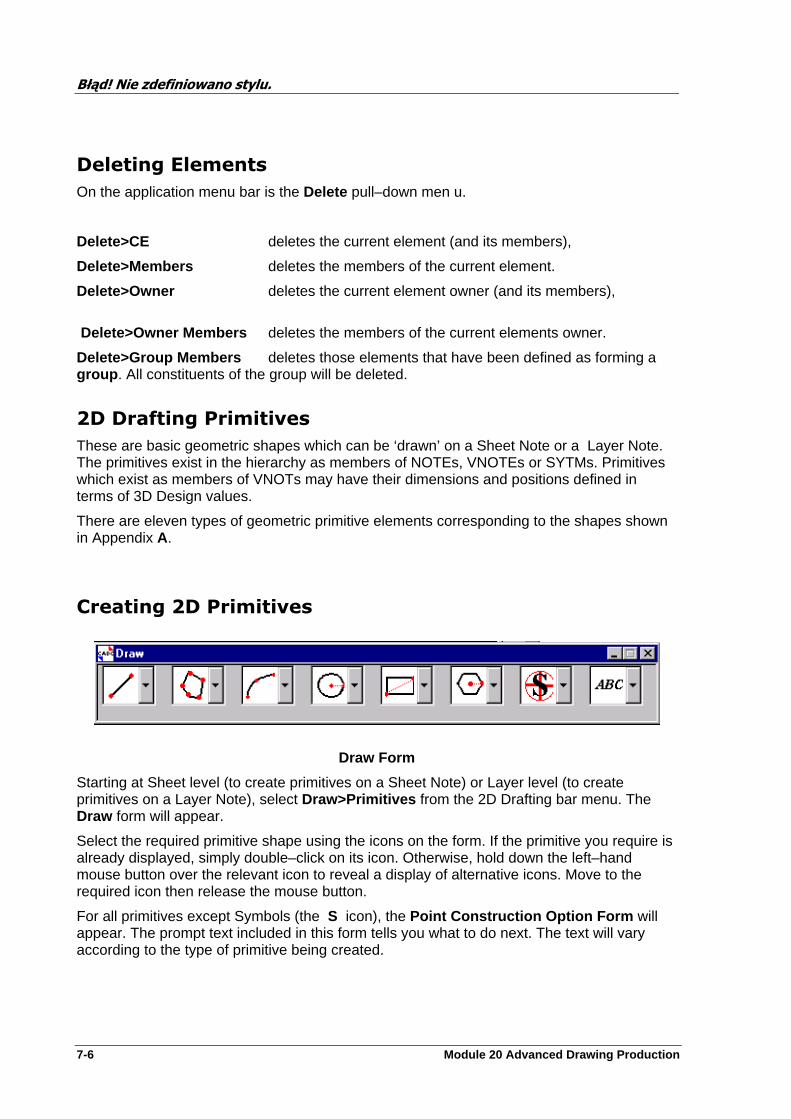
Błąd! Nie zdefiniowano stylu.
7-6 Module 20 Advanced Drawing Production
Deleting Elements
On the application menu bar is the Delete pull–down men u.
Delete>CE deletes the current element (and its members),
Delete>Members deletes the members of the current element.
Delete>Owner deletes the current element owner (and its members),
Delete>Owner Members deletes the members of the current elements owner.
Delete>Group Members deletes those elements that have been defined as forming a group . All constituents of the group will be deleted.
2D Drafting Primitives
These are basic geometric shapes which can be ‘drawn’ on a Sheet Note or a Layer Note. The primitives exist in the hierarchy as members of NOTEs, VNOTEs or SYTMs. Primitives which exist as members of VNOTs may have their dimensions and positions defined in terms of 3D Design values.
There are eleven types of geometric primitive elements corresponding to the shapes shown in Appendix A.
Creating 2D Primitives
Draw Form
Starting at Sheet level (to create primitives on a Sheet Note) or Layer level (to create primitives on a Layer Note), select Draw>Primitives from the 2D Drafting bar menu. The Draw form will appear.
Select the required primitive shape using the icons on the form. If the primitive you require is already displayed, simply double–click on its icon. Otherwise, hold down the left–hand mouse button over the relevant icon to reveal a display of alternative icons. Move to the required icon then release the mouse button.
For all primitives except Symbols (the S icon), the Point Construction Option Form will appear. The prompt text included in this form tells you what to do next. The text will vary according to the type of primitive being created.
Błąd! Nie zdefiniowano stylu.
Module 20 Advanced Drawing Production 7-7
Constructed Points
The point construction options (listed under the Option button on the Point Construction Option Form ) enable you to position primitives at points defined in terms of other points rather than at explicit (or cursor–derived) positions. For example, the endpoint of a line could be defined as being at the endpoint of an arc, or at the centre of a circle.
Use the cursor to define the drafting points for the primitive concerned. A drafting point in this context is a position reference for the primitive. For example a line has a ‘From point’ and a ‘To point’ or a midpoint, a circle has a centre, etc.
Select from the Option button the type of point you wish to use for each drafting point of the primitive, then proceed as indicated by the prompt text on the Point Construction Option Form . When you have finished, Cancel the form.
The point construction options may be interpreted as follows.
2d Cursor hit simply requires a cursor hit, as when not using point construction at all. This option will usually be at the top of the Option list (as the default point construction option), although this can be changed.
End point of derives a position as the endpoint of an existing primitive. This would typically be a line or an arc, but it could also be the end of a line within a closed polyline primitive (i.e. a rectangle, triangle etc), or a line or arc within an outline (open or closed). Click on the appropriate primitive (nearest the endpoint that you wish to use). Line definitions of other elements (such as one side of an EQUI, or a line that comprises a piece of a design item shown in a VIEW) may be extracted by the cursor.
Centre pt of derives a position as the centre of an existing circle, arc, ellipse, rectangle, hexagon, table, diamond or equilateral triangle. Click on the primitive whose centre point you wish to use.
Mid point of derives a position as the midpoint of an existing line or arc. Click on the primitive whose midpoint you wish to use. The required midpoint could also be that of one side of a closed polyline primitive, e.g. a rectangle or an outline. Line definitions of other elements (such as a line that comprises a piece of a design item shown in a VIEW) can be extracted by cursor.
Mid pt between derives a position as the midpoint of two other points. Each point to be used could be a simple 2D position or a drafting point on an existing primitive.
Intersection at derives a position as the point at the intersection of two primitives, which must be chosen from the set straight line (which could be one side of a closed polyline primitive, e.g. a rectangle), arc or circle , although line–parts of more complex primitives may be identified by cursor. An ellipse is also an allowable primitive, but it is only possible to calculate the intersection point between an ellipse and a straight line.
Inter. between derives a position as the point at the intersection of two cursor–identified primitives.
NOTE: In the case of connected lines , continual clicking in response to the Identify To point message will create a series of connected lines until Cancel is clicked on. With orthogonal lines, the ‘To points’ need only be input approximately.
In the case of Outlines , the Point Construction Option Form gives the further options of Straight or Curved spans to be drawn to the cursor–identified vertex point. An option to close the outline (i.e. draw a span from the last vertex back to the first) is also given. When

Błąd! Nie zdefiniowano stylu.
7-8 Module 20 Advanced Drawing Production
inserting a new vertex, a straight span will result if the TO and THROUGH points are coincident, a curved span otherwise.
Creating 2D Primitives from Icon Selection
Line Creation
This calls the Point Construction form from which you may choose how to define your first point (From Point). After defining the from point you may, if required, change the point definition option. Now make a second point definition (To Point), a straight line will be drawn connecting the two points and the points will be removed. If you require a line of a known length you must create it as above and then use Edit > Primitive to set the length or other attributes.
Linked set of straight lines
This follows the same rules as above, although in this case you may define as many points as is required. After defining the to point of the last line click the cancel button on the Point Construction form to end.
Follows the same rules as for Linked Straight Lines but moves the to point so that the line created is always perpendicular to the previous line.
Allows you to sketch a line between design points and 2D or 3D points. Set the type of point for the From and To points, and press Create new line. You will be prompted to pick the points. The ends of the line can be repositioned by pressing the Position buttons. You will be prompted to pick a new position.
Outlines
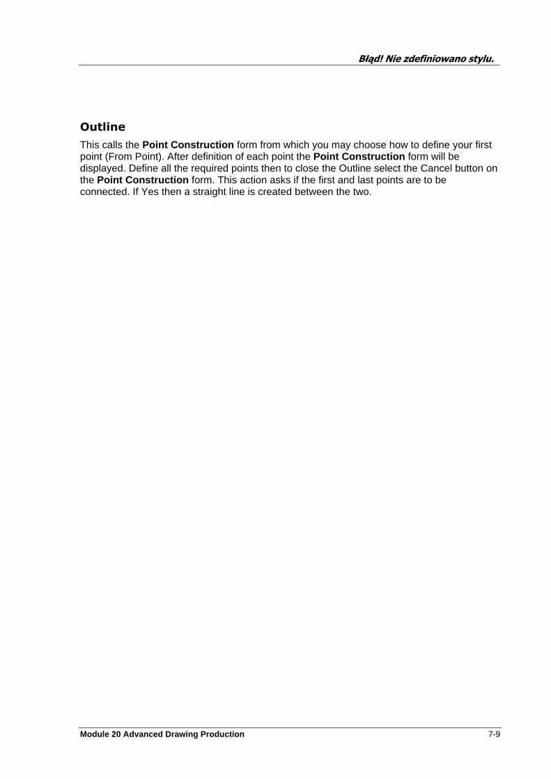
Błąd! Nie zdefiniowano stylu.
Module 20 Advanced Drawing Production 7-9
Outline
This calls the Point Construction form from which you may choose how to define your first point (From Point). After definition of each point the Point Construction form will be displayed. Define all the required points then to close the Outline select the Cancel button on the Point Construction form. This action asks if the first and last points are to be connected. If Yes then a straight line is created between the two.
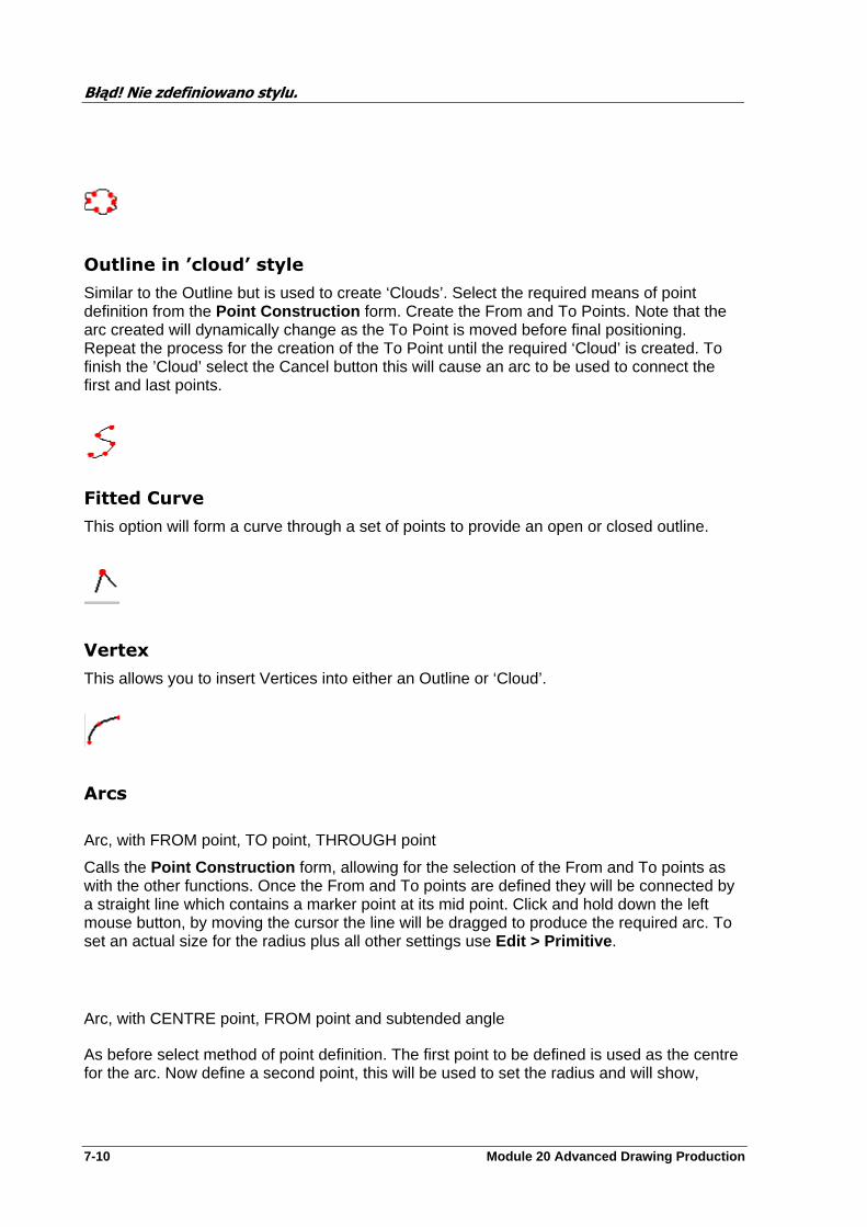
Błąd! Nie zdefiniowano stylu.
7-10 Module 20 Advanced Drawing Production
Outline in ’cloud’ style
Similar to the Outline but is used to create ‘Clouds’. Select the required means of point definition from the Point Construction form. Create the From and To Points. Note that the arc created will dynamically change as the To Point is moved before final positioning. Repeat the process for the creation of the To Point until the required ‘Cloud’ is created. To finish the ’Cloud’ select the Cancel button this will cause an arc to be used to connect the first and last points.
Fitted Curve
This option will form a curve through a set of points to provide an open or closed outline.
Vertex
This allows you to insert Vertices into either an Outline or ‘Cloud’.
Arcs
Arc, with FROM point, TO point, THROUGH point
Calls the Point Construction form, allowing for the selection of the From and To points as with the other functions. Once the From and To points are defined they will be connected by a straight line which contains a marker point at its mid point. Click and hold down the left mouse button, by moving the cursor the line will be dragged to produce the required arc. To set an actual size for the radius plus all other settings use Edit > Primitive .
Arc, with CENTRE point, FROM point and subtended angle
As before select method of point definition. The first point to be defined is used as the centre for the arc. Now define a second point, this will be used to set the radius and will show,

Błąd! Nie zdefiniowano stylu.
Module 20 Advanced Drawing Production 7-11
temporarily, a line joining the centre and radius points. Now define a third point. This creates the angle required for the arc. Note: the arc is drawn between the second and third points.
Circles
Circle, defined by radius.
This requires two points to be defined. The first point is the centre of the circle, the second is the radius. If when defining the radius point the left mouse key is held down a circle will be displayed which can have its size changed dynamically by moving the cursor.
Circle, defined by diameter
This also requires definition of two points, the first being a point on the circumference. The second is the corresponding point on the opposite side of the circle. As with the above holding the mouse key down during positioning of the second point will allow dynamic size control.
Ellipse
Like circle diameter creation, two points are again required this time relating to the height and width of the ellipse. The first and second point are used to define the width and can be dynamically sized as before. After the second point is positioned an ellipse is displayed. Note, the point displayed at the mid point on one of the edges is used to control the height of the ellipse. Click the left mouse key and hold, now move the mouse causing the height of the ellipse to change.
Rectangle, defined by diagonal
Requires points to be defined that are opposite. As with all the functions holding down the mouse key before final positioning will dynamically display the primitive.
Błąd! Nie zdefiniowano stylu.
7-12 Module 20 Advanced Drawing Production
Table
Table, defined by opposite corner points
This works in exactly the same way as creation of a rectangle. The difference is that after the second point is positioned the rectangle is divided into columns and rows, as defined by the defaults. These can be changed by Edit > Primitive .
Hexagon
Hexagon, defined by circumscribed radius
This is defined by its centre and radius. Define a point which is to be the centre of the hexagon followed by the point which defines the circumscribed radius.
Hexagon, defined by circumscribed diameter
This also requires definition of two points, the first being a point on the circumference. The second is the corresponding point on the opposite side of the hexagon. As with the above holding the mouse key down during positioning of the second point will allow dynamic size control.
Triangle
Equilateral triangle
Definition of two points will create an Equilateral triangle.
Diamond
Like ellipses, creation is via two points which relate to its height and width. The first and second point are used to define the width and can be dynamically sized as before. After the second point is positioned a diamond is displayed. Note, the point displayed at the
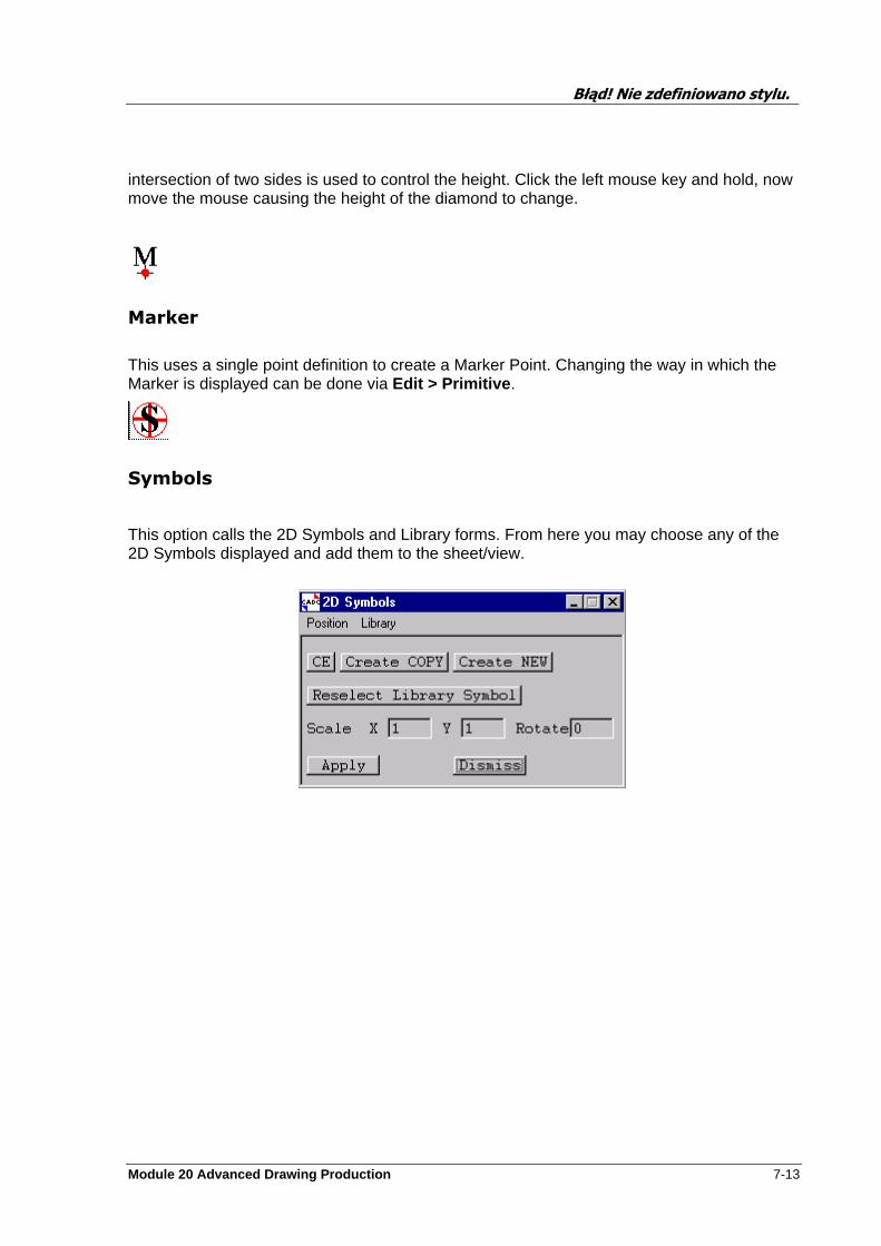
Błąd! Nie zdefiniowano stylu.
Module 20 Advanced Drawing Production 7-13
intersection of two sides is used to control the height. Click the left mouse key and hold, now move the mouse causing the height of the diamond to change.
Marker
This uses a single point definition to create a Marker Point. Changing the way in which the Marker is displayed can be done via Edit > Primitive .
Symbols
This option calls the 2D Symbols and Library forms. From here you may choose any of the 2D Symbols displayed and add them to the sheet/view.
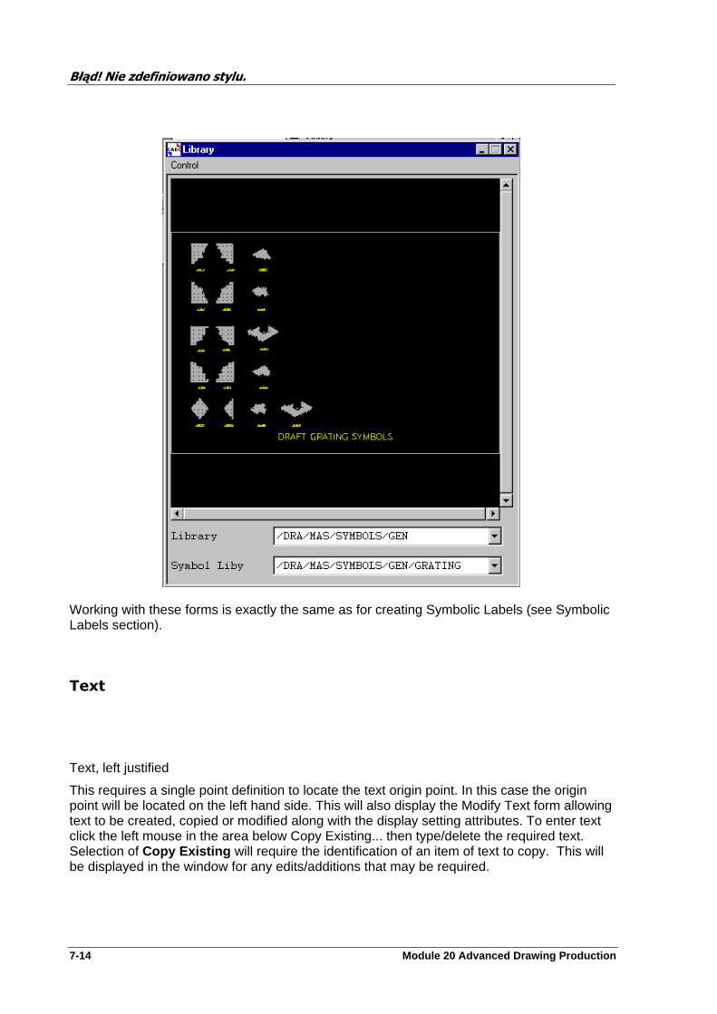
Błąd! Nie zdefiniowano stylu.
7-14 Module 20 Advanced Drawing Production
Working with these forms is exactly the same as for creating Symbolic Labels (see Symbolic Labels section).
Text
Text, left justified
This requires a single point definition to locate the text origin point. In this case the origin point will be located on the left hand side. This will also display the Modify Text form allowing text to be created, copied or modified along with the display setting attributes. To enter text click the left mouse in the area below Copy Existing... then type/delete the required text. Selection of Copy Existing will require the identification of an item of text to copy. This will be displayed in the window for any edits/additions that may be required.
Błąd! Nie zdefiniowano stylu.
Module 20 Advanced Drawing Production 7-15
Text, left justified. This is the same as above.
Text, centre justified
This requires a single point definition to locate the text origin point. In this case the origin point will be located at the middle of the bottom most line of text. This will also display the Modify Text form allowing text to be created, copied or modified along with the display setting attributes. To enter text click the left mouse in the area below Copy Existing... then type/delete the required text. Selection of Copy Existing will require the identification of an item of text to copy, this will be displayed in the window for any edits/additions that may be required.
Text, right justified
This requires a single point definition to locate the text origin point. In this case the origin point will be located on the right hand side. This will also display the Modify Text form allowing text to be created, copied or modified along with the display setting attributes. To enter text click the left mouse in the area below Copy Existing... then type/delete the required text. Selection of Copy Existing will require the identification of an item of text to copy, this will be displayed in the window for any edits/additions that may be required.
Miscellaneous Construction Options
All topics covered in this section may be selected from the Construct option from the 2D Drafting bar menu.
Group
The group option is selected by Construct>Group , this will display Group form. This selection does not create a group element but links all the selected elements together in such a way that Draft can track all the items owned by a group. Using groups allows you to carry out the same operation on a number of elements simultaneously.

Błąd! Nie zdefiniowano stylu.
7-16 Module 20 Advanced Drawing Production
Group Form
The selection of primitives to be included in the group may be carried out by any one of three methods, these being Identified , Crossing and Window . Identified: allows the selection of individual elements. Crossing: allows you to define a region selecting all elements that are either totally or partly within the defined area.
Window: allows you to define a region selecting all elements that are totally within the defined area.
After choosing the required method of element selection click the Add button, this will display a form asking that the elements are identified or that a region is defined. After completion of the selection, all group members will be changed to display the colour set, as a default, by the Setting>Group Colour option from the 2D Drafting bar menu.
The Clear button will remove all elements from the group and return them back to their original colour. Remove allows individual elements to be removed from the group and returned to the original colour.
The Perform Action On Group button displays the form of the same name which is used to enter, by syntax, the operation you wish to carry out on the group, ie.
nlpn 6 this will change the noteline pen to show the elements as a thick dashed line style.
by y20 moves all group elements 20 units in the +Y direction.
The Filter button allows the setting up of selection criteria to help in only selecting the required elements. You may not wish to select any arcs that are green from a particular Note/Vnote so by setting the Filter these items will not be selected.
2D Copy
After choosing this option a message is displayed requesting the selection of a 2D primitive. You may select as many primitives as you wish. To finish the selection click the Cancel

Błąd! Nie zdefiniowano stylu.
Module 20 Advanced Drawing Production 7-17
button. You must then provide an origin point. This point will be used to position the copy. Now define a point that will be used to calculate the displacement.
Repeat
Offset; a message will be displayed asking for all the 2D primitives required to be identified. Now you must identify an origin point, the displacement is set by defining a second point which must also be defined. The definition of the two points will display the Offset Copy form with the values of the points already entered, you may change these if required. Click OK when ready.
Rows & Columns; a message will be displayed asking for all 2D primitives required to be identified. Now complete the Rows & Columns form for the spacing and number of rows and columns required.
Polar; a message will be displayed asking for the all 2D primitives required to be identified. Now define a point which is to be used as the centre of rotation. Once defined, the Polar form will be displayed showing the settings for the point you defined. Complete this form as required and click OK.
Mirror
A message will be displayed asking for all 2D primitives required to be identified. To define the Mirror Axis you may use one of three methods. Cursor - define two points to produce a temporary line which is used as the axis. Identified Line - select a 2D primitive line that will be used as the axis. The last option requires you to enter the position via the keyboard or cursor selections.
Chamfers
Identify the lines to which the chamfer is to be applied. (The ‘first’ and ‘second’ lines to be hit correspond to ‘Line 1’ and ‘Line 2’ to which the chamfer offsets were applied.
Finally identify the ‘quadrant’ where the chamfer line is to appear. This is obvious where two lines have common start/end points (as in the example on the previous page), but in the case of two crossing lines any one of four quadrants may be chosen.
Fillets
Identify the lines to which the fillet is to be applied, and finally identify the ‘quadrant’ where the fillet arc is to appear. This is obvious where two lines have common start/end points, but in the case of two crossing lines any one of four quadrants may be chosen.
Parallel Lines
Identify the line that is to be copied. A copy will be created at a default setting which can be altered on the Parallel Line form. The Invert button changes the direction of the copy
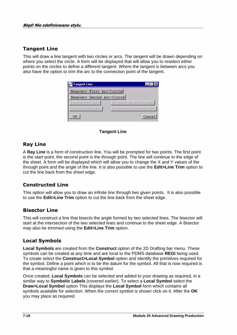
Błąd! Nie zdefiniowano stylu.
7-18 Module 20 Advanced Drawing Production
Tangent Line
This will draw a line tangent with two circles or arcs. The tangent will be drawn depending on where you select the circle. A form will be displayed that will allow you to reselect either points on the circles to define a different tangent. Where the tangent is between arcs you also have the option to trim the arc to the connection point of the tangent.
Tangent Line
Ray Line
A Ray Line is a form of construction line. You will be prompted for two points. The first point is the start point, the second point is the through point. The line will continue to the edge of the sheet. A form will be displayed which will allow you to change the X and Y values of the through point and the angle of the line. It is also possible to use the Edit>Line Trim option to cut the line back from the sheet edge.
Constructed Line
This option will allow you to draw an infinite line through two given points. It is also possible to use the Edit>Line Trim option to cut the line back from the sheet edge.
Bisector Line
This will construct a line that bisects the angle formed by two selected lines. The bisector will start at the intersection of the two selected lines and continue to the sheet edge. A Bisector may also be trimmed using the Edit>Line Trim option.
Local Symbols
Local Symbols are created from the Construct option of the 2D Drafting bar menu. These symbols can be created at any time and are local to the PDMS database REGI being used. To create select the Construct>Local Symbol option and Identify the primitives required for the symbol. Define a point which is to be the datum for the symbol. All that is now required is that a meaningful name is given to this symbol.
Once created, Local Symbols can be selected and added to your drawing as required, in a similar way to Symbolic Labels (covered earlier). To select a Local Symbol select the Draw>Local Symbol option This displays the Local Symbol form which contains all symbols available for selection. When the correct symbol is shown click on it. After the OK you may place as required.
Błąd! Nie zdefiniowano stylu.
Module 20 Advanced Drawing Production 7-19
NOTE: Local Symbols are your own personal symbols and are not available to other users. The definition will be lost on leaving PDMS unless you do a Display>Save>Forms and Display . The graphics will remain on the sheet however.
Edit
Edit>Primitive - This allows you to alter the attribute settings for the selected primitive. Before selection of this option you must have already selected the primitive to be edited. Once selected the Modify ‘primitive type’ Attributes form will be displayed to allow the resetting of the attributes. When finished click Apply , Reset will return the last saved settings.
Edit>Move Primitive/Node To - Note that when the the Edit>Move Primitive/Node To is selected that all nodes on all primitives will be shown to aid selection. Once selected, depending on the option selected from the submenu, a form will be displayed for you to position were this node should now be positioned. Note centres of arcs, circles etc. are not moved.
Edit>Move Primitive By -This allows you to move the whole primitive by a distance which is either calculated by the entering of two cursor points or entering the amount to move in the X and Y directions.
Edit>Move Node By - This allows you to reposition a Node on a primitive thereby changing the shape of the primitive.
Edit>Line Gap - Allows the creation of a Gap which may have a length of Zero , Default or defined by its Start and Finish points.
Edit>Line Trim - Is used to Trim line or arc to another arc or line which is to be selected.
Edit>Rotate - This will allow the selected element/s to be rotated about a selected point by a user defined angle.
Edit>Demolish Symbol - This will break the links created when defining a Local Symbol see above.
Edit>Action Group - This will call up the Perform Action on Group form were you can enter syntax to perform a particular action on the whole group, ie change the colour that its displayed in etc.
2D Settings
Global Settings
See Section 9 for details on the main Global Settings.
Group Filter
This calls the Group Filtering form from which you may set the defaults required to be used when building groups
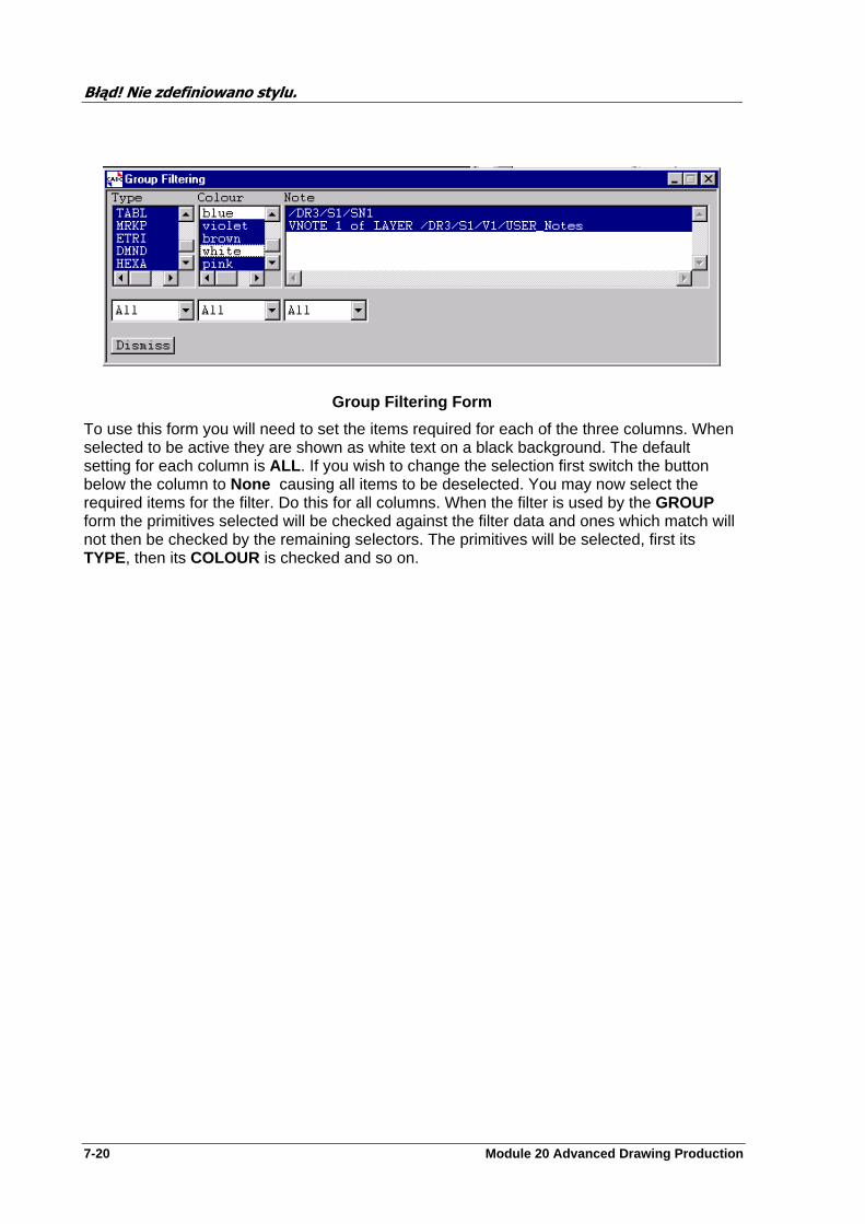
Błąd! Nie zdefiniowano stylu.
7-20 Module 20 Advanced Drawing Production
Group Filtering Form
To use this form you will need to set the items required for each of the three columns. When selected to be active they are shown as white text on a black background. The default setting for each column is ALL . If you wish to change the selection first switch the button below the column to None causing all items to be deselected. You may now select the required items for the filter. Do this for all columns. When the filter is used by the GROUP form the primitives selected will be checked against the filter data and ones which match will not then be checked by the remaining selectors. The primitives will be selected, first its TYPE, then its COLOUR is checked and so on.
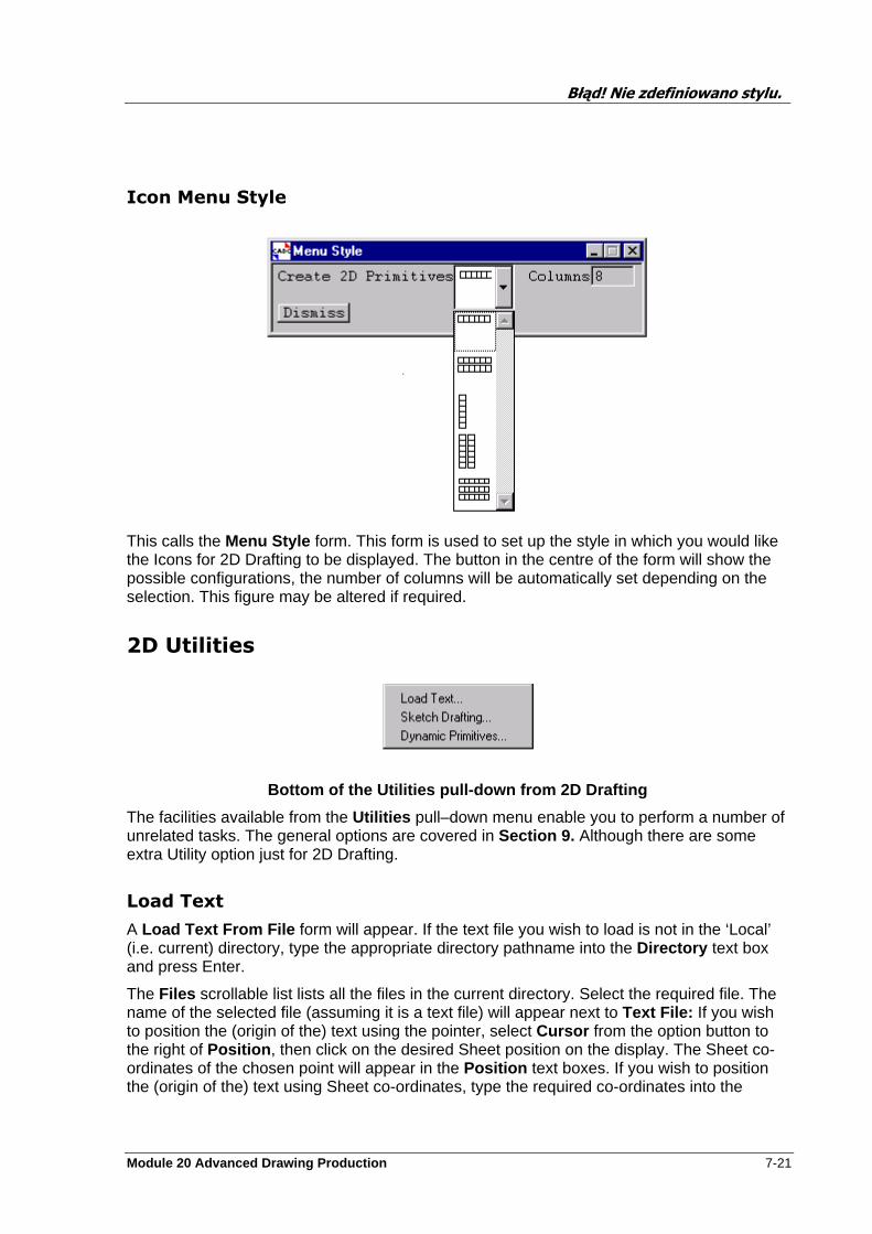
Błąd! Nie zdefiniowano stylu.
Module 20 Advanced Drawing Production 7-21
Icon Menu Style
This calls the Menu Style form. This form is used to set up the style in which you would like the Icons for 2D Drafting to be displayed. The button in the centre of the form will show the possible configurations, the number of columns will be automatically set depending on the selection. This figure may be altered if required.
2D Utilities
Bottom of the Utilities pull-down from 2D Drafting
The facilities available from the Utilities pull–down menu enable you to perform a number of unrelated tasks. The general options are covered in Section 9. Although there are some extra Utility option just for 2D Drafting.
Load Text
A Load Text From File form will appear. If the text file you wish to load is not in the ‘Local’ (i.e. current) directory, type the appropriate directory pathname into the Directory text box and press Enter.
The Files scrollable list lists all the files in the current directory. Select the required file. The name of the selected file (assuming it is a text file) will appear next to Text File: If you wish to position the (origin of the) text using the pointer, select Cursor from the option button to the right of Position , then click on the desired Sheet position on the display. The Sheet co-ordinates of the chosen point will appear in the Position text boxes. If you wish to position the (origin of the) text using Sheet co-ordinates, type the required co-ordinates into the
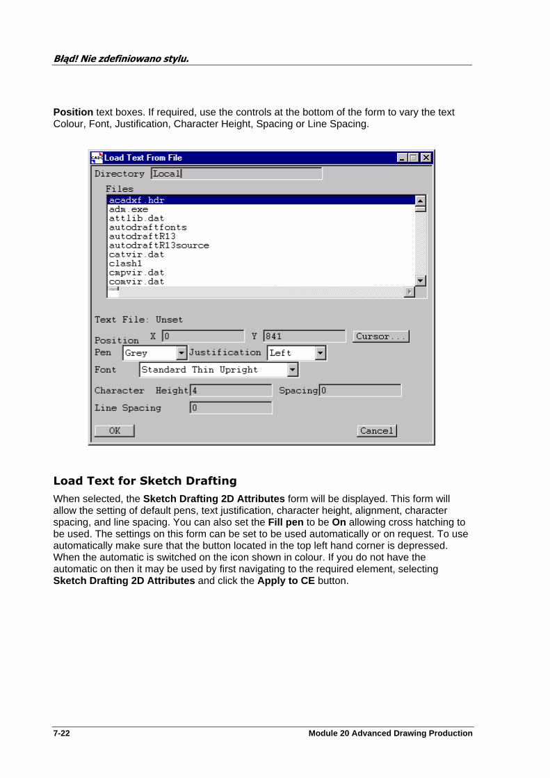
Błąd! Nie zdefiniowano stylu.
7-22 Module 20 Advanced Drawing Production
Position text boxes. If required, use the controls at the bottom of the form to vary the text Colour, Font, Justification, Character Height, Spacing or Line Spacing.
Load Text for Sketch Drafting
When selected, the Sketch Drafting 2D Attributes form will be displayed. This form will allow the setting of default pens, text justification, character height, alignment, character spacing, and line spacing. You can also set the Fill pen to be On allowing cross hatching to be used. The settings on this form can be set to be used automatically or on request. To use automatically make sure that the button located in the top left hand corner is depressed. When the automatic is switched on the icon shown in colour. If you do not have the automatic on then it may be used by first navigating to the required element, selecting Sketch Drafting 2D Attributes and click the Apply to CE button.
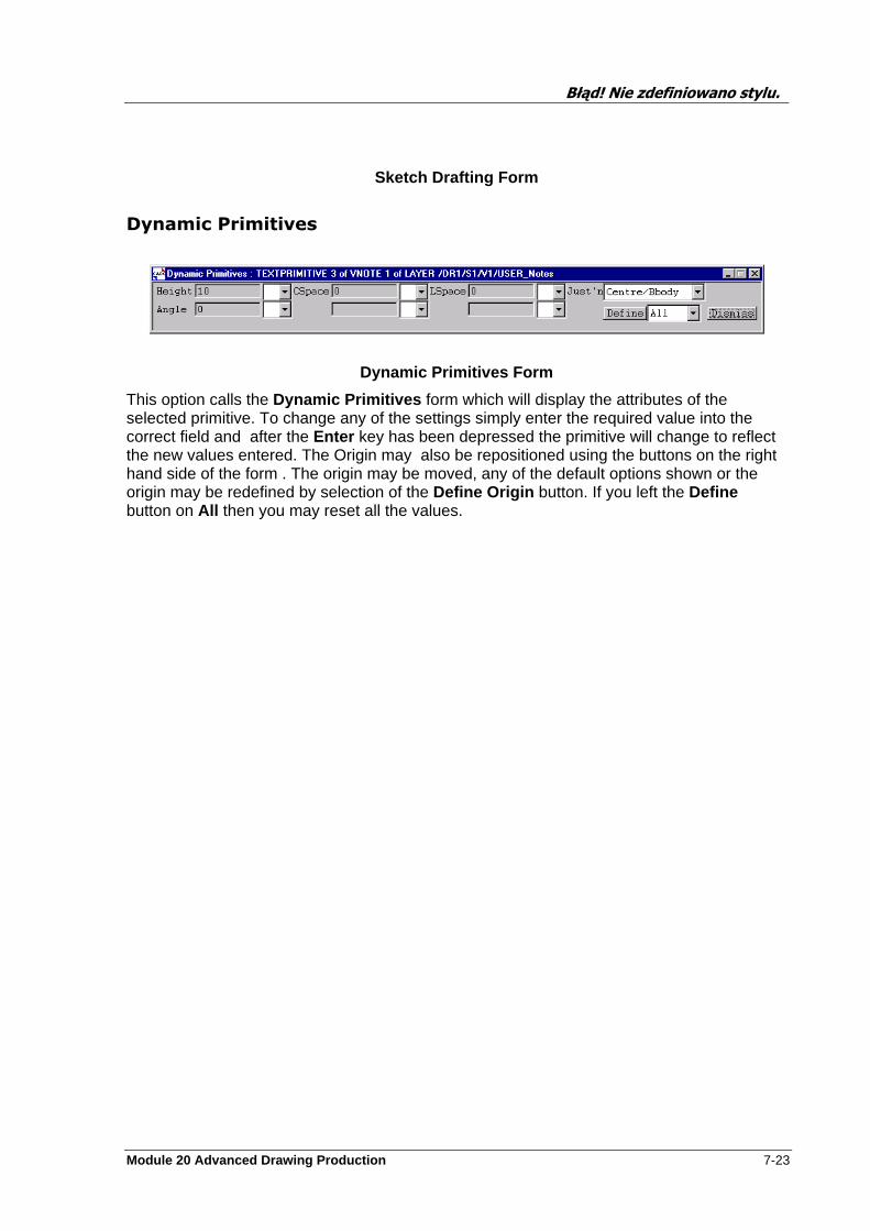
Błąd! Nie zdefiniowano stylu.
Module 20 Advanced Drawing Production 7-23
Sketch Drafting Form
Dynamic Primitives
Dynamic Primitives Form
This option calls the Dynamic Primitives form which will display the attributes of the selected primitive. To change any of the settings simply enter the required value into the correct field and after the Enter key has been depressed the primitive will change to reflect the new values entered. The Origin may also be repositioned using the buttons on the right hand side of the form . The origin may be moved, any of the default options shown or the origin may be redefined by selection of the Define Origin button. If you left the Define button on All then you may reset all the values.
Błąd! Nie zdefiniowano stylu.
7-24 Module 20 Advanced Drawing Production
Exercise
Note: The drawings created do not have to be the same as those in the example sheets found in Appendix F.
Create a copy of the sheet containing the section views. Create an Outline around the cut items and cross-hatch.
Create a new sheet on which to create 2D Draft Primitives, try one of each option. You may if you wish use the different primitives to create a 2D shape. You have a choice of lines, arcs, circles, rectangles, hexagons, triangles and diamonds.
Create a table
Create some text, trying some of the possible variants, bottom left justified, etc.
Select a 2D Symbol from library and place it on the sheet.
Try the different options under Construct to create fillets, chamfers mirror copies etc.
Create a revision cloud.
Add extra Vertices to either a cloud or outline.
Construct a local symbol from some of the 2D primitives and place it on the sheet.
Module 20 Advanced Drawing Production 8-1
Automatic Drawing Production (ADP)
Changing Application
To enter the Auto Drawing Production (ADP) Application select the following from the DRAFT General bar menu:
Draft > Auto Drawing Production
This will close the application you are currently running and load the Dimensioning application. Change of application can be carried out from any DRAFT applications ie.
Dimensioning ---- 2D Drafting or Labels ----------- General and so on.
This time the change of application is performed by selection of the Auto Drawing Production option from Draft on the top bar menu.
Once the application has been loaded, you will see that the DRAFT General bar menu has been replaced with DRAFT Auto Drawing Production bar menu. The first four options (Draft-Query) have not changed, these are the same in every application. The other options on this menu are exclusively for the creation and modifying of auto drawing production.
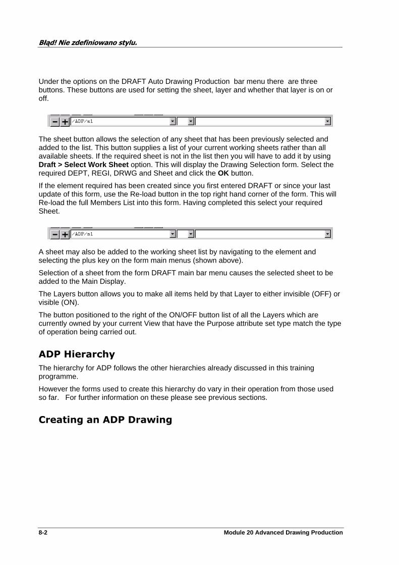
Błąd! Nie zdefiniowano stylu.
8-2 Module 20 Advanced Drawing Production
Under the options on the DRAFT Auto Drawing Production bar menu there are three buttons. These buttons are used for setting the sheet, layer and whether that layer is on or off.
The sheet button allows the selection of any sheet that has been previously selected and added to the list. This button supplies a list of your current working sheets rather than all available sheets. If the required sheet is not in the list then you will have to add it by using Draft > Select Work Sheet option. This will display the Drawing Selection form. Select the required DEPT, REGI, DRWG and Sheet and click the OK button.
If the element required has been created since you first entered DRAFT or since your last update of this form, use the Re-load button in the top right hand corner of the form. This will Re-load the full Members List into this form. Having completed this select your required Sheet.
A sheet may also be added to the working sheet list by navigating to the element and selecting the plus key on the form main menus (shown above).
Selection of a sheet from the form DRAFT main bar menu causes the selected sheet to be added to the Main Display.
The Layers button allows you to make all items held by that Layer to either invisible (OFF) or visible (ON).
The button positioned to the right of the ON/OFF button list of all the Layers which are currently owned by your current View that have the Purpose attribute set type match the type of operation being carried out.
ADP Hierarchy
The hierarchy for ADP follows the other hierarchies already discussed in this training programme.
However the forms used to create this hierarchy do vary in their operation from those used so far. For further information on these please see previous sections.
Creating an ADP Drawing
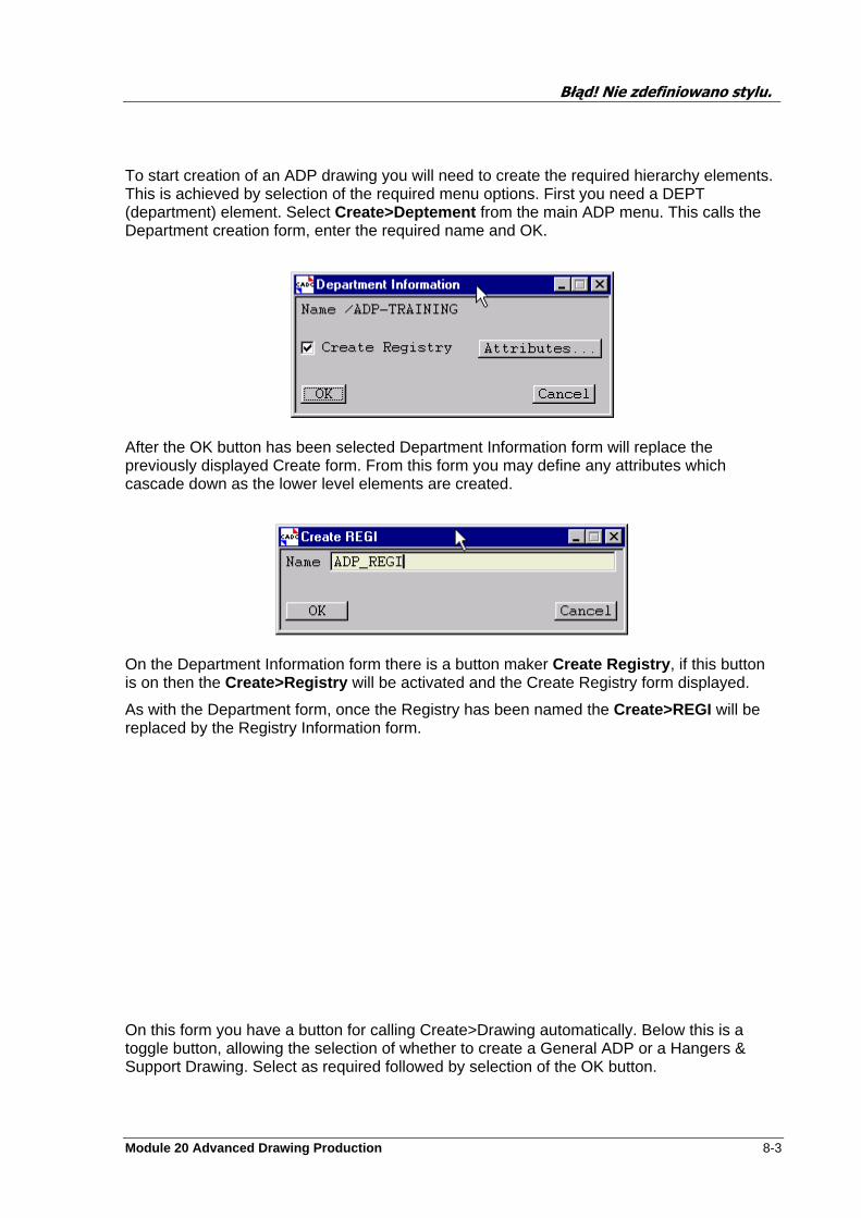
Błąd! Nie zdefiniowano stylu.
Module 20 Advanced Drawing Production 8-3
To start creation of an ADP drawing you will need to create the required hierarchy elements. This is achieved by selection of the required menu options. First you need a DEPT (department) element. Select Create>Deptement from the main ADP menu. This calls the Department creation form, enter the required name and OK.
After the OK button has been selected Department Information form will replace the previously displayed Create form. From this form you may define any attributes which cascade down as the lower level elements are created.
On the Department Information form there is a button maker Create Registry , if this button is on then the Create>Registry will be activated and the Create Registry form displayed.
As with the Department form, once the Registry has been named the Create>REGI will be replaced by the Registry Information form.
On this form you have a button for calling Create>Drawing automatically. Below this is a toggle button, allowing the selection of whether to create a General ADP or a Hangers & Support Drawing. Select as required followed by selection of the OK button.
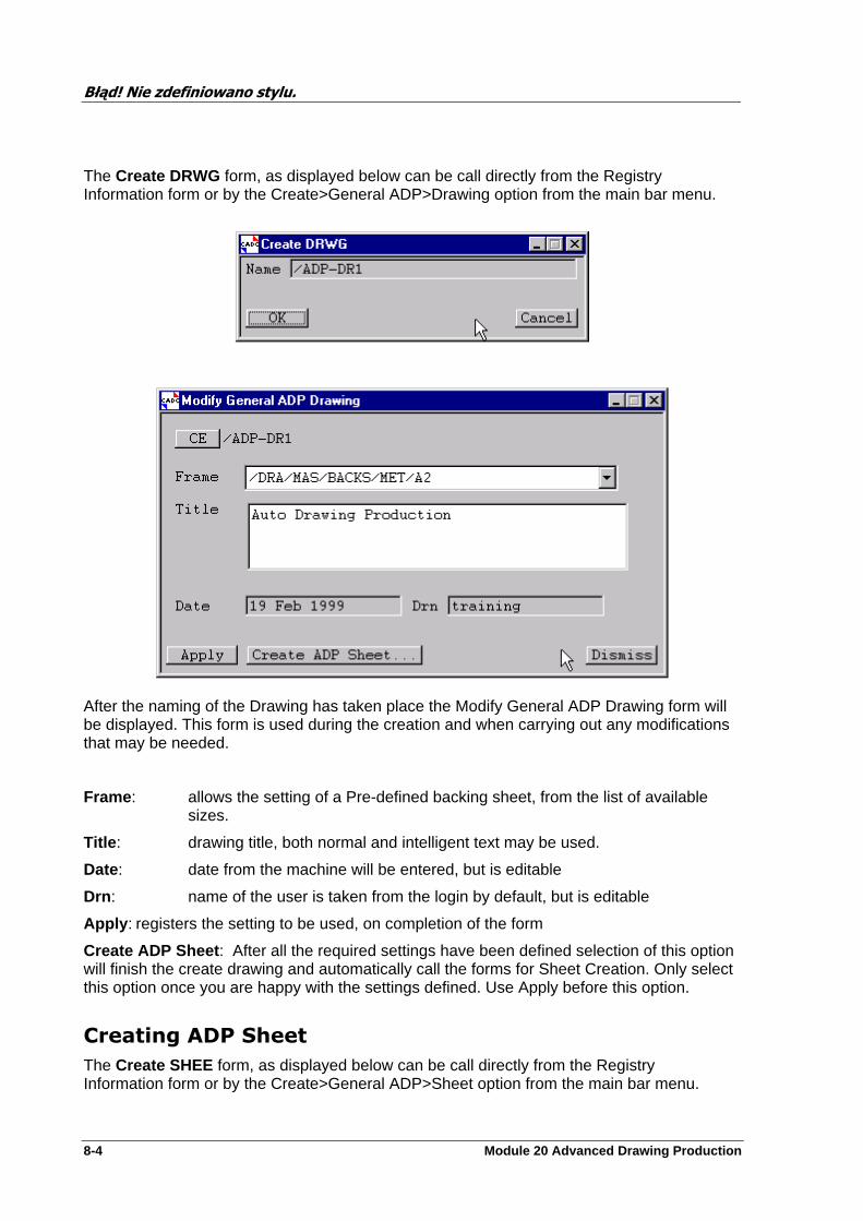
Błąd! Nie zdefiniowano stylu.
8-4 Module 20 Advanced Drawing Production
The Create DRWG form, as displayed below can be call directly from the Registry Information form or by the Create>General ADP>Drawing option from the main bar menu.
After the naming of the Drawing has taken place the Modify General ADP Drawing form will be displayed. This form is used during the creation and when carrying out any modifications that may be needed.
Frame : allows the setting of a Pre-defined backing sheet, from the list of available sizes.
Title : drawing title, both normal and intelligent text may be used.
Date: date from the machine will be entered, but is editable
Drn : name of the user is taken from the login by default, but is editable
Apply : registers the setting to be used, on completion of the form
Create ADP Sheet : After all the required settings have been defined selection of this option will finish the create drawing and automatically call the forms for Sheet Creation. Only select this option once you are happy with the settings defined. Use Apply before this option.
Creating ADP Sheet
The Create SHEE form, as displayed below can be call directly from the Registry Information form or by the Create>General ADP>Sheet option from the main bar menu.

Błąd! Nie zdefiniowano stylu.
Module 20 Advanced Drawing Production 8-5
After the naming of the Drawing has taken place the Modify General ADP Drawing form will be displayed along with the ADP Drawing under creation Note the fields from the Drawing form are now displayed on the backing sheet
This form is used during the creation and when carrying out any modifications that may be needed.
ADP Drawing during sheet creation.
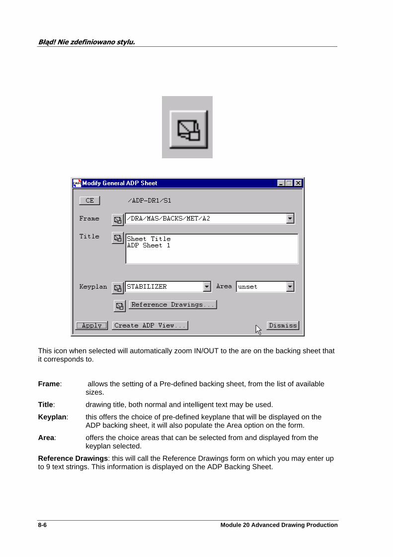
Błąd! Nie zdefiniowano stylu.
8-6 Module 20 Advanced Drawing Production
This icon when selected will automatically zoom IN/OUT to the are on the backing sheet that it corresponds to.
Frame : allows the setting of a Pre-defined backing sheet, from the list of available sizes.
Title : drawing title, both normal and intelligent text may be used.
Keyplan : this offers the choice of pre-defined keyplane that will be displayed on the ADP backing sheet, it will also populate the Area option on the form.
Area : offers the choice areas that can be selected from and displayed from the keyplan selected.
Reference Drawings : this will call the Reference Drawings form on which you may enter up to 9 text strings. This information is displayed on the ADP Backing Sheet.
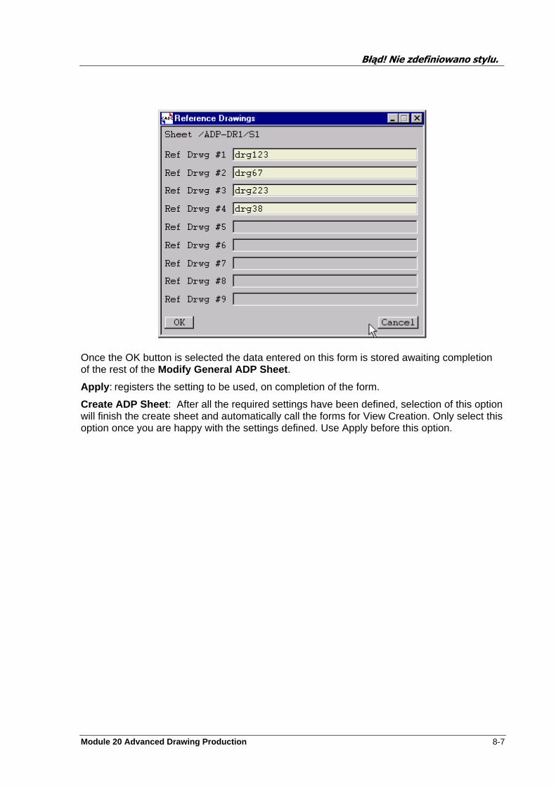
Błąd! Nie zdefiniowano stylu.
Module 20 Advanced Drawing Production 8-7
Once the OK button is selected the data entered on this form is stored awaiting completion of the rest of the Modify General ADP Sheet .
Apply : registers the setting to be used, on completion of the form.
Create ADP Sheet : After all the required settings have been defined, selection of this option will finish the create sheet and automatically call the forms for View Creation. Only select this option once you are happy with the settings defined. Use Apply before this option.

Błąd! Nie zdefiniowano stylu.
8-8 Module 20 Advanced Drawing Production
ADP Drawing After Sheet Creation
Note: the settings from the sheet form are placed onto the backing sheet when the Apply button is selected.
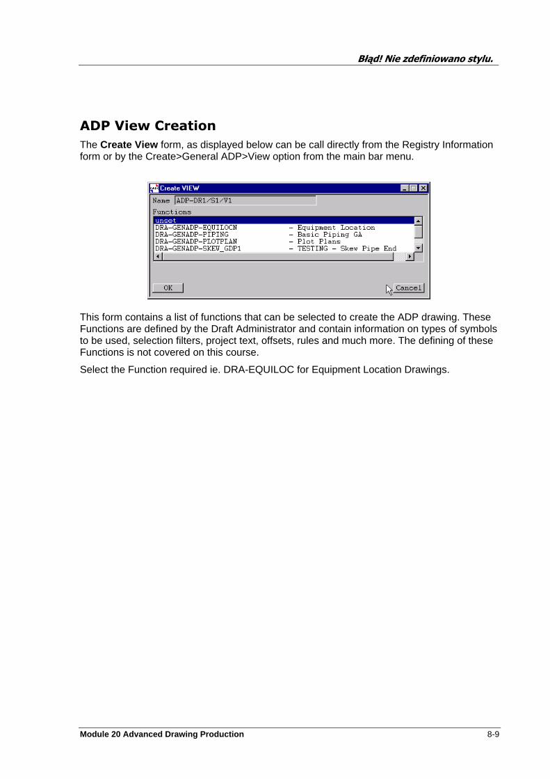
Błąd! Nie zdefiniowano stylu.
Module 20 Advanced Drawing Production 8-9
ADP View Creation
The Create View form, as displayed below can be call directly from the Registry Information form or by the Create>General ADP>View option from the main bar menu.
This form contains a list of functions that can be selected to create the ADP drawing. These Functions are defined by the Draft Administrator and contain information on types of symbols to be used, selection filters, project text, offsets, rules and much more. The defining of these Functions is not covered on this course.
Select the Function required ie. DRA-EQUILOC for Equipment Location Drawings.
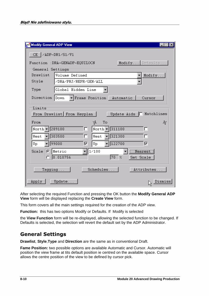
Błąd! Nie zdefiniowano stylu.
8-10 Module 20 Advanced Drawing Production
After selecting the required Function and pressing the OK button the Modify General ADP View form will be displayed replacing the Create View form.
This form covers all the main settings required for the creation of the ADP view.
Function: this has two options Modify or Defaults. If Modify is selected
the View Function form will be re-displayed, allowing the selected function to be changed. If Defaults is selected, the selection will revert the default set by the ADP Administrator.
General Settings
Drawlist , Style ,Type and Direction are the same as in conventional Draft.
Fame Position: two possible options are available Automatic and Cursor. Automatic will position the view frame at tits default position ie centred on the available space. Cursor allows the centre position of the view to be defined by cursor pick.
Błąd! Nie zdefiniowano stylu.
Module 20 Advanced Drawing Production 8-11
Limits
There are four buttons at the op of this section of the form. These being From Drawlist , From Keyplan , Update Aids and Matchlines .
From Drawlist: sets the limits, From/To , to the extremes, including all elements in the Drawlist.
From Keyplan: sets the limits, From/To , to the values set for the Area selected for the Keyplan.
Update Aids: when selected this will display graphically the frame size that will now result from the change in scale. Note that if the scale has not benn altered then a error is returned.
Matchlines: simple On/Off toggle switch for displaying the Matchline limits or not.
From / To: displays the limits calculated from the Drawlist or Using the setting stored with the selected Area. Note that these values may be locked or edited as required.
Scale: as with conventional Draft the Set Scale button will calculate the maximum scale that can be used for the present view size. The Nearest will convert the maximum scale, calculated via set scale, to the nearest standard scale on the list.
To the left of the Set Scale button is a percentage ,%, window. This is used in conjunction this Set Scale and is the percentage of available space the view is allowed to use. Note set the required percentage and press Set Scale to view the changes.
The last three buttons allow selection of the required types to be used for Tagging, Schedules and Attributes to be used. Each of these will be now looked at.

Błąd! Nie zdefiniowano stylu.
8-12 Module 20 Advanced Drawing Production
Tagging
Tagging: calls the tagging form
This is a dynamic form. The options available are created by the ADP Administrator and can have any number of option placed on the form. To use simple pick any options that you want used on the ADP Drawing followed by Dismiss. The Update option is used for modification once the Drawing is created and you simple wish to change the selected options. Update will cause these changes to be reflected in the drawing.
Schedules
Schedules: calls the Schedules form
This works in the same way as Tagging.

Błąd! Nie zdefiniowano stylu.
Module 20 Advanced Drawing Production 8-13
Attributes
Attributes: calls the General ADP View Attributes form. This allows the defining of defaults form the current ADP View. The function over each of these attributes is covered in the Creating Views earlier in this document.
Once all selection have been made press the Apply button on the Modify General ADP View form. Changes can still be made and applied again. When you are read to move on to the next stage use the Update button. Note once this is selected any changes will require the selections to be made via the modify options.
Selecting Update will call the View Update form.
Update: select the types to be Updated (added to drawing)
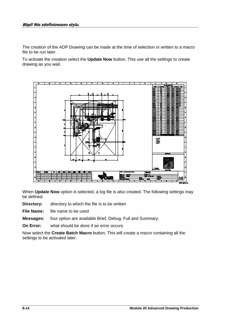
Błąd! Nie zdefiniowano stylu.
8-14 Module 20 Advanced Drawing Production
The creation of the ADP Drawing can be made at the time of selection or written to a macro file to be run later.
To activate the creation select the Update Now button. This use all the settings to create drawing as you wait.
When Update Now option is selected, a log file is also created. The following settings may be defined.
Directory: directory to which the file is to be written
File Name: file name to be used
Messages: four option are available Brief, Debug, Full and Summary.
On Error: what should be done if an error occurs
Now select the Create Batch Macro button. This will create a macro containing all the settings to be activated later.
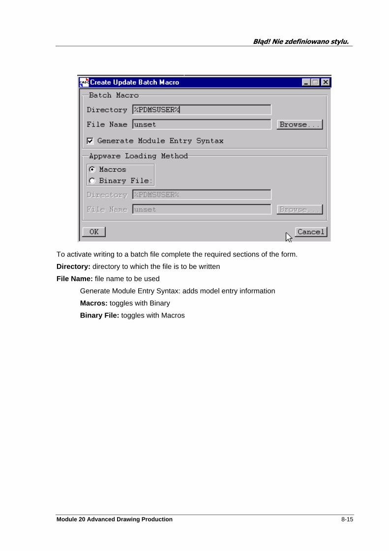
Błąd! Nie zdefiniowano stylu.
Module 20 Advanced Drawing Production 8-15
To activate writing to a batch file complete the required sections of the form.
Directory: directory to which the file is to be written
File Name: file name to be used
Generate Module Entry Syntax: adds model entry information
Macros: toggles with Binary
Binary File: toggles with Macros

Błąd! Nie zdefiniowano stylu.
8-16 Module 20 Advanced Drawing Production
Sample file created by Macros
Błąd! Nie zdefiniowano stylu.
Module 20 Advanced Drawing Production 8-17
Sample file created by Batch
Błąd! Nie zdefiniowano stylu.
8-18 Module 20 Advanced Drawing Production
Exercise
Create an ADP drawing for Equipment GA.
Change the Schedule on the Drawing you created.
Create a second ADP Drawing try using the batch mode option
Module 20 Advanced Drawing Production 9-1
Settings
The facilities available from the Settings pull–down menu enable you to perform a number of unrelated tasks.
System
Beep on Error.
From this form you can specify I you want an audible warning when a error has occurred.
Show Main Toolbar.
Allows you to run Draft without the Main Tool Bar being displayed.
Large Icons
This option will display the Icons on the Toolbar with using an increased size.
Click window to raise
Allows a simple click on the anywhere in or on the window to cause it to brought forward.
System Setting form
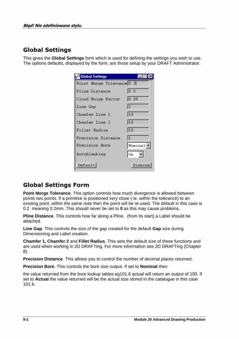
Błąd! Nie zdefiniowano stylu.
9-2 Module 20 Advanced Drawing Production
Global Settings
This gives the Global Settings form which is used for defining the settings you wish to use. The options defaults, displayed by the form, are those setup by your DRAFT Administrator.
Global Settings Form
Point Merge Tolerance . This option controls how much divergence is allowed between points two points. If a primitive is positioned very close ( ie. within the tolerance) to an existing point, within the same note then the point will be re-used. The default in this case is 0.2 meaning 0.2mm. This should never be set to 0 as this may cause problems.
Pline Distance . This controls how far along a Pline, (from its start) a Label should be attached.
Line Gap . This controls the size of the gap created for the default Gap size during Dimensioning and Label creation.
Chamfer 1, Chamfer 2 and Fillet Radius . This sets the default size of these functions and are used when working in 2D DRAFTing. For more information see 2D DRAFTing (Chapter 8).
Precision Distance . This allows you to control the number of decimal places returned.
Precision Bore . This controls the bore size output. If set to Nominal then
the value returned from the bore lookup tables eg101.6 actual will return an output of 100. If set to Actual the value returned will be the actual size stored in the catalogue in this case 101.6.
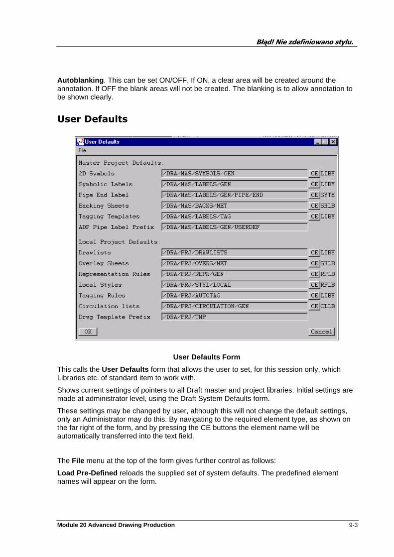
Błąd! Nie zdefiniowano stylu.
Module 20 Advanced Drawing Production 9-3
Autoblanking . This can be set ON/OFF. If ON, a clear area will be created around the annotation. If OFF the blank areas will not be created. The blanking is to allow annotation to be shown clearly.
User Defaults
User Defaults Form
This calls the User Defaults form that allows the user to set, for this session only, which Libraries etc. of standard item to work with.
Shows current settings of pointers to all Draft master and project libraries. Initial settings are made at administrator level, using the Draft System Defaults form.
These settings may be changed by user, although this will not change the default settings, only an Administrator may do this. By navigating to the required element type, as shown on the far right of the form, and by pressing the CE buttons the element name will be automatically transferred into the text field.
The File menu at the top of the form gives further control as follows:
Load Pre-Defined reloads the supplied set of system defaults. The predefined element names will appear on the form.
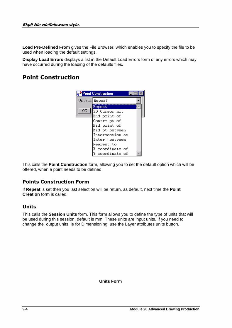
Błąd! Nie zdefiniowano stylu.
9-4 Module 20 Advanced Drawing Production
Load Pre-Defined From gives the File Browser, which enables you to specify the file to be used when loading the default settings.
Display Load Errors displays a list in the Default Load Errors form of any errors which may have occurred during the loading of the defaults files.
Point Construction
This calls the Point Construction form, allowing you to set the default option which will be offered, when a point needs to be defined.
Points Construction Form
If Repeat is set then you last selection will be return, as default, next time the Point Creation form is called.
Units
This calls the Session Units form. This form allows you to define the type of units that will be used during this session, default is mm. These units are input units. If you need to change the output units, ie for Dimensioning, use the Layer attributes units button.
Units Form
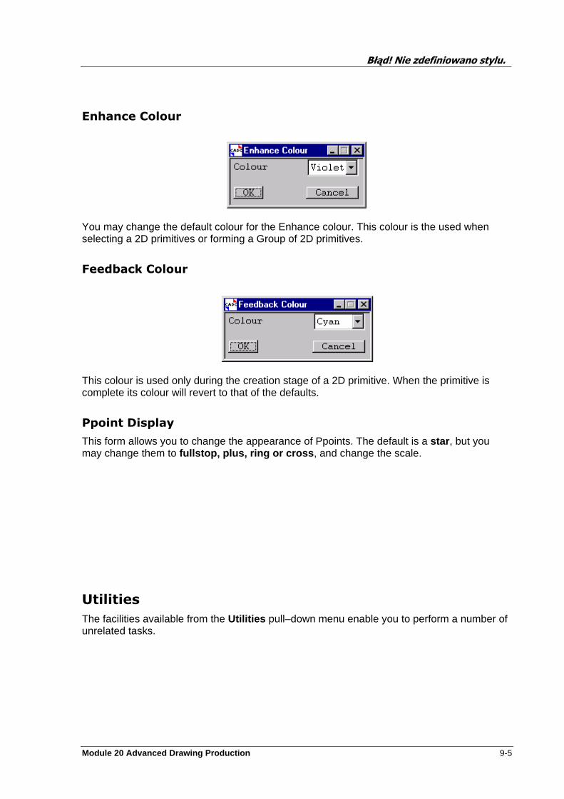
Błąd! Nie zdefiniowano stylu.
Module 20 Advanced Drawing Production 9-5
Enhance Colour
You may change the default colour for the Enhance colour. This colour is the used when selecting a 2D primitives or forming a Group of 2D primitives.
Feedback Colour
This colour is used only during the creation stage of a 2D primitive. When the primitive is complete its colour will revert to that of the defaults.
Ppoint Display
This form allows you to change the appearance of Ppoints. The default is a star , but you may change them to fullstop, plus, ring or cross , and change the scale.
Utilities
The facilities available from the Utilities pull–down menu enable you to perform a number of unrelated tasks.
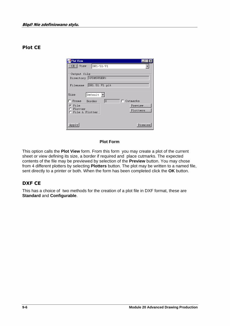
Błąd! Nie zdefiniowano stylu.
9-6 Module 20 Advanced Drawing Production
Plot CE
Plot Form
This option calls the Plot View form. From this form you may create a plot of the current sheet or view defining its size, a border if required and place cutmarks. The expected contents of the file may be previewed by selection of the Preview button. You may chose from 4 different plotters by selecting Plotters button. The plot may be written to a named file, sent directly to a printer or both. When the form has been completed click the OK button.
DXF CE
This has a choice of two methods for the creation of a plot file in DXF format, these are Standard and Configurable .
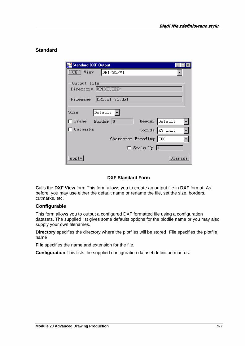
Błąd! Nie zdefiniowano stylu.
Module 20 Advanced Drawing Production 9-7
Standard
DXF Standard Form
Calls the DXF View form This form allows you to create an output file in DXF format. As before, you may use either the default name or rename the file, set the size, borders, cutmarks, etc.
Configurable
This form allows you to output a configured DXF formatted file using a configuration datasets. The supplied list gives some defaults options for the plotfile name or you may also supply your own filenames.
Directory specifies the directory where the plotfiles will be stored File specifies the plotfile name
File specifies the name and extension for the file.
Configuration This lists the supplied configuration dataset definition macros:
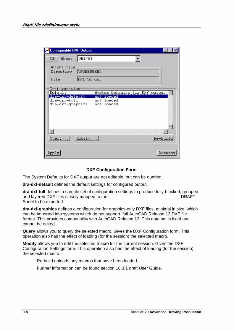
Błąd! Nie zdefiniowano stylu.
9-8 Module 20 Advanced Drawing Production
DXF Configuration Form
The System Defaults for DXF output are not editable, but can be queried,
dra-dxf-default defines the default settings for configured output.
dra-dxf-full defines a sample set of configuration settings to produce fully-blocked, grouped and layered DXF files closely mapped to the DRAFT Sheet to be exported.
dra-dxf-graphics defines a configuration for graphics-only DXF files, minimal in size, which can be imported into systems which do not support full AutoCAD Release 13 DXF file format. This provides compatibility with AutoCAD Release 12. This data set is fixed and cannot be edited.
Query allows you to query the selected macro. Gives the DXF Configuration form. This operation also has the effect of loading (for the session) the selected macro.
Modify allows you to edit the selected macro for the current session. Gives the DXF Configuration Settings form. This operation also has the effect of loading (for the session) the selected macro.
Re-build unloads any macros that have been loaded.
Further information can be found section 16.3.1 draft User Guide.
Błąd! Nie zdefiniowano stylu.
Module 20 Advanced Drawing Production 9-9
Clash Plotting
This facility enables you to generate plot of clashing Design items using a special clash report template macro file .
To do this you will need to generate this file using Design Clash Detection.
The Report Macro template file required by Draft is called DRA-GEN-CLASHTEMP and
must be copied from %PDMSDFLTS% to your user area.
To produce the required macro, in DESIGN type the following syntax:
Map Build New MDB makes sure your db is upto date
DESCLASH enter DESCLASH module REMOVE OBST ALL empties obstruction list OBST /PIPES set the obstruction elements CHECKADD /EQUIP set what is to be checked. REPORT MACRO /
DRA-GEN-CLASHTEMP open template to use ALPHA FILE /name open/create file for input clash report OUTPUT this enters all clashes from above check. ALPHA FILE END closes the input clash report file REPORT MACRO END close template in use EXIT return to Design module
In DRAFT, select Utilities>Clash Plotting to display the Clash Plotting form.
Clash Report
Enter the name of the alpha file produced in DESIGN. This file is used by Draft to determine the relevant clash data for each clash in the report.
Clash Sheet
The template CADCENTRE supply may be found in /DRA/PRJ/TMP/CLASH . You may enter this by navigating to the element in the members list and by pressing the CE button the name will be automatically transferred.
Clash Run ID
You may type a single text string (no spaces) that may be a header on the plot. Note that this text string must not contain spaces.
Run Live
Will execute the instructions now.

Błąd! Nie zdefiniowano stylu.
9-10 Module 20 Advanced Drawing Production
Preview
Clash Plotting form
Will call a preview window where you can see the results before you action the execution.
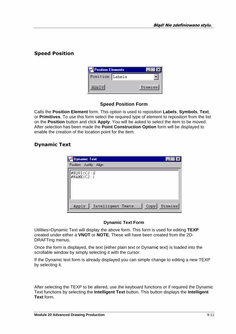
Błąd! Nie zdefiniowano stylu.
Module 20 Advanced Drawing Production 9-11
Speed Position
Speed Position Form
Calls the Position Element form. This option is used to reposition Labels , Symbols , Text , or Primitives . To use this form select the required type of element to reposition from the list on the Position button and click Apply . You will be asked to select the item to be moved. After selection has been made the Point Construction Option form will be displayed to enable the creation of the location point for the item.
Dynamic Text
Dynamic Text Form
Utilities>Dynamic Text will display the above form. This form is used for editing TEXP created under either a VNOT or NOTE. These will have been created from the 2D-DRAFTing menus.
Once the form is displayed, the text (either plain text or Dynamic text) is loaded into the scrollable window by simply selecting it with the cursor.
If the Dynamic text form is already displayed you can simple change to editing a new TEXP by selecting it.
After selecting the TEXP to be altered, use the keyboard functions or if required the Dynamic Text functions by selecting the Intelligent Text button. This button displays the Intelligent Text form.
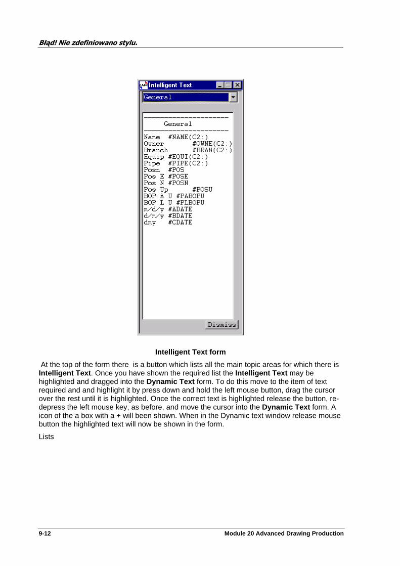
Błąd! Nie zdefiniowano stylu.
9-12 Module 20 Advanced Drawing Production
Intelligent Text form
At the top of the form there is a button which lists all the main topic areas for which there is Intelligent Text . Once you have shown the required list the Intelligent Text may be highlighted and dragged into the Dynamic Text form. To do this move to the item of text required and and highlight it by press down and hold the left mouse button, drag the cursor over the rest until it is highlighted. Once the correct text is highlighted release the button, re-depress the left mouse key, as before, and move the cursor into the Dynamic Text form. A icon of the a box with a + will been shown. When in the Dynamic text window release mouse button the highlighted text will now be shown in the form.
Lists
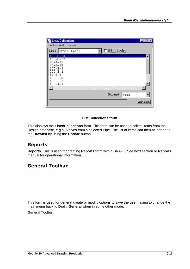
Błąd! Nie zdefiniowano stylu.
Module 20 Advanced Drawing Production 9-13
List/Collections form
This displays the Lists/Collections form. This form can be used to collect items from the Design database, e.g all Valves from a selected Pipe. The list of items can then be added to the Drawlist by using the Update button.
Reports
Reports . This is used for creating Reports from within DRAFT. See next section or Reports manual for operational information.
General Toolbar
This form is used for general create or modify options to save the user having to change the main menu back to Draft>General when in some other mode.
General Toolbar
Błąd! Nie zdefiniowano stylu.
9-14 Module 20 Advanced Drawing Production
DB Listing
This form enables you to output all or part of the database, including element attributes, as a text file. It can be used in three different modes:
DB Listing. This outputs a listing of the specified parts of the database in its current state.
DB Changes . This outputs a listing of the changes to the specified parts of the database as a macro which can be run in to return the database to the state it was in at the given time or session. You can edit the macro file so that only the required elements are changed.
DB Differences . This outputs a listing of the specified parts of the database, with the old and new elements and attributes changed or added since the given time or session.
The mode affects which parts of the form are active (inactive parts are greyed out). The mode is changed using the options under Control on the menu at the top of the form. The form title will change to reflect the selected mode.
DB Listing form
See HELP text or manuals for further information on this subject.
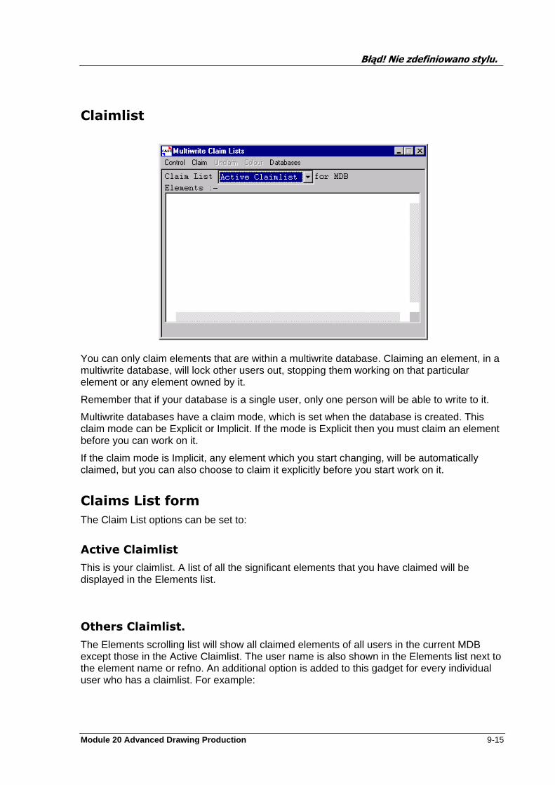
Błąd! Nie zdefiniowano stylu.
Module 20 Advanced Drawing Production 9-15
Claimlist
You can only claim elements that are within a multiwrite database. Claiming an element, in a multiwrite database, will lock other users out, stopping them working on that particular element or any element owned by it.
Remember that if your database is a single user, only one person will be able to write to it.
Multiwrite databases have a claim mode, which is set when the database is created. This claim mode can be Explicit or Implicit. If the mode is Explicit then you must claim an element before you can work on it.
If the claim mode is Implicit, any element which you start changing, will be automatically claimed, but you can also choose to claim it explicitly before you start work on it.
Claims List form
The Claim List options can be set to:
Active Claimlist
This is your claimlist. A list of all the significant elements that you have claimed will be displayed in the Elements list.
Others Claimlist.
The Elements scrolling list will show all claimed elements of all users in the current MDB except those in the Active Claimlist. The user name is also shown in the Elements list next to the element name or refno. An additional option is added to this gadget for every individual user who has a claimlist. For example:
Błąd! Nie zdefiniowano stylu.
9-16 Module 20 Advanced Drawing Production
USERA Claimlist
Note that clicking on any element in the Elements list will navigate to that element.
VIEW Types
Module 20 Advanced Drawing Production A-1
View Types
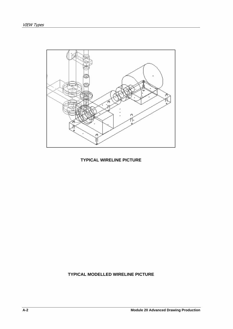
VIEW Types
A-2 Module 20 Advanced Drawing Production
TYPICAL WIRELINE PICTURE
TYPICAL MODELLED WIRELINE PICTURE
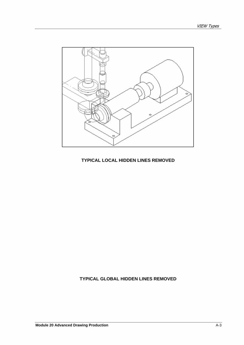
VIEW Types
Module 20 Advanced Drawing Production A-3
TYPICAL LOCAL HIDDEN LINES REMOVED
TYPICAL GLOBAL HIDDEN LINES REMOVED
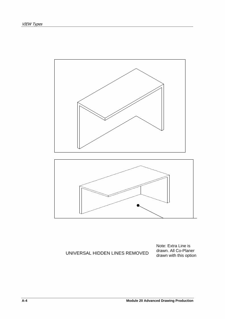
VIEW Types
A-4 Module 20 Advanced Drawing Production
TYPICAL GLOBAL HIDDEN LINES REMOVED
TYPICAL UNIVERSAL HIDDEN
UNIVERSAL HIDDEN LINES REMOVED
Note: Extra Line is drawn. All Co-Planer drawn with this option
VIEW Types
Module 20 Advanced Drawing Production A-5
2D Drafting Primitive Icons
The icons have the following meanings:
Sketch Line

VIEW Types
A-6 Module 20 Advanced Drawing Production
Alternative Character Set
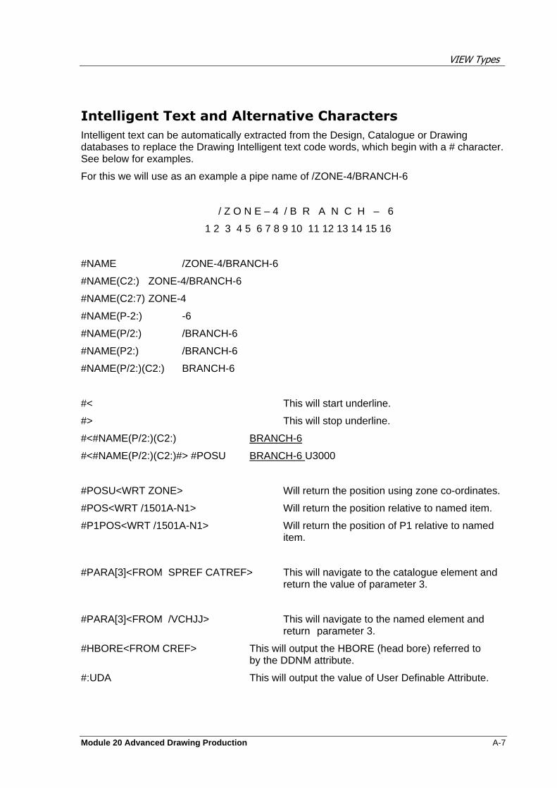
VIEW Types
Module 20 Advanced Drawing Production A-7
Intelligent Text and Alternative Characters
Intelligent text can be automatically extracted from the Design, Catalogue or Drawing databases to replace the Drawing Intelligent text code words, which begin with a # character. See below for examples.
For this we will use as an example a pipe name of /ZONE-4/BRANCH-6
/ Z O N E – 4 / B R A N C H – 6
1 2 3 4 5 6 7 8 9 10 11 12 13 14 15 16
#NAME /ZONE-4/BRANCH-6
#NAME(C2:) ZONE-4/BRANCH-6
#NAME(C2:7) ZONE-4
#NAME(P-2:) -6
#NAME(P/2:) /BRANCH-6
#NAME(P2:) /BRANCH-6
#NAME(P/2:)(C2:) BRANCH-6
#< This will start underline.
#> This will stop underline.
#<#NAME(P/2:)(C2:) BRANCH-6
#<#NAME(P/2:)(C2:)#> #POSU BRANCH-6 U3000
#POSU<WRT ZONE> Will return the position using zone co-ordinates.
#POS<WRT /1501A-N1> Will return the position relative to named item.
#P1POS<WRT /1501A-N1> Will return the position of P1 relative to named item.
#PARA[3]<FROM SPREF CATREF> This will navigate to the catalogue element and return the value of parameter 3.
#PARA[3]<FROM /VCHJJ> This will navigate to the named element and return parameter 3.
#HBORE<FROM CREF> This will output the HBORE (head bore) referred to by the DDNM attribute.
#:UDA This will output the value of User Definable Attribute.

VIEW Types
A-8 Module 20 Advanced Drawing Production
The Alternative Character set provides useful symbols for the users. To use these the tilde character (~) must precede the required code for the symbol required. They can be mixed with Intelligent text. See code sheet from the manual page 10-3 or the Training manual Appendix A-5.
~C This will produce a Centerline symbol.
~C#POSU Will produce the Centreline symbol followed by the position.
When using Intelligent Text and Alternative Characters, gaps used are important. Normal text may be used also.
#<~C#NAME(C2:)#> POSITION IS #POSU This will return the Centerline symbol and name of the attached element, all underlined, followed by a normal text message plus its position.

DRAFT Database Hierarchy
Module 20 Advanced Drawing Production B-1
DRAFT Database Hierarchy
DRAFT Database Hierarchy
B-2 Module 20 Advanced Drawing Production
DRAFT Database Hierarchy
Module 20 Advanced Drawing Production B-3


Dimension Example Sheets
Module 20 Advanced Drawing Production D-1
Dimension Example Sheets
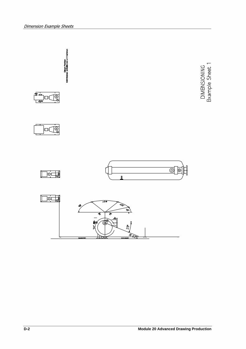
Dimension Example Sheets
D-2 Module 20 Advanced Drawing Production

Dimension Example Sheets
Module 20 Advanced Drawing Production D-3

Dimension Example Sheets
D-4 Module 20 Advanced Drawing Production

Dimension Example Sheets
Module 20 Advanced Drawing Production D-5
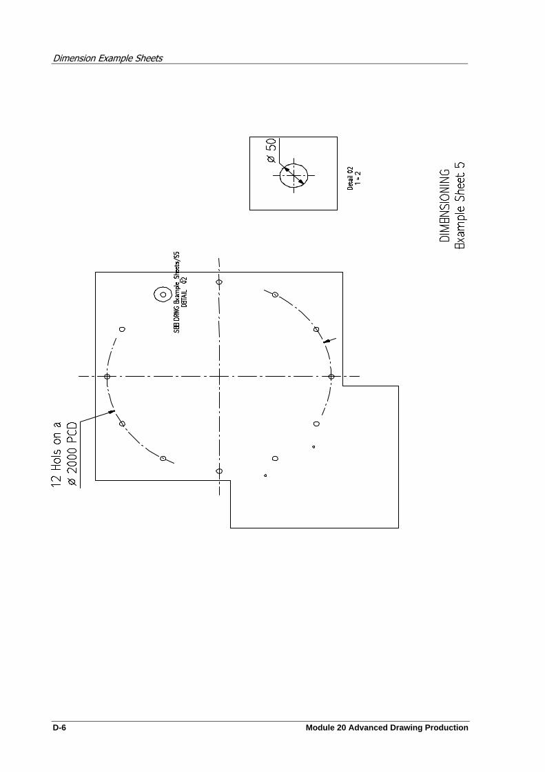
Dimension Example Sheets
D-6 Module 20 Advanced Drawing Production
Label Example Sheets
Module 20 Advanced Drawing Production D-1
Label Example Sheets
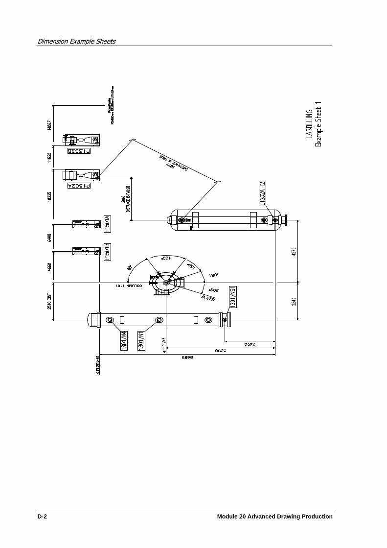
Dimension Example Sheets
D-2 Module 20 Advanced Drawing Production
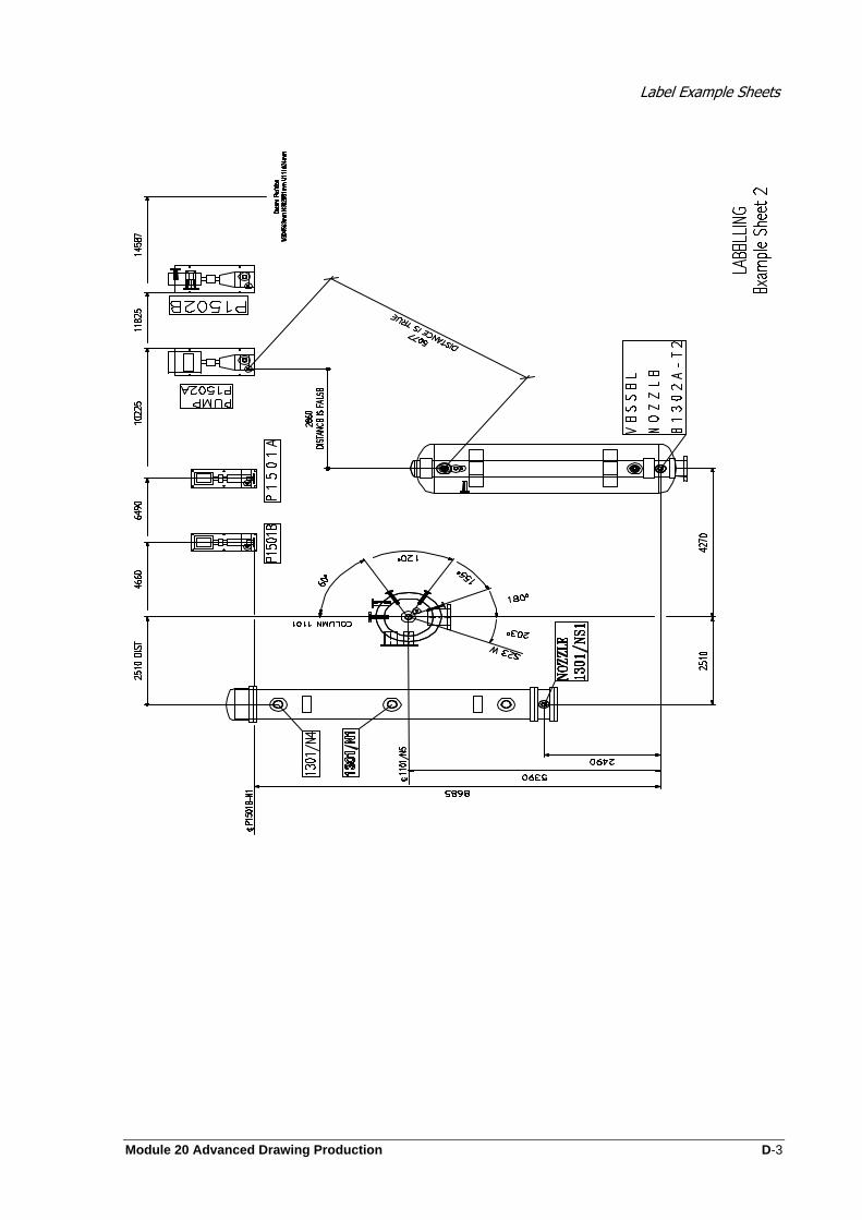
Label Example Sheets
Module 20 Advanced Drawing Production D-3
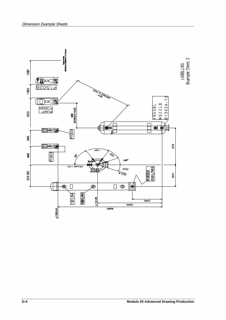
Dimension Example Sheets
D-4 Module 20 Advanced Drawing Production

Label Example Sheets
Module 20 Advanced Drawing Production D-5
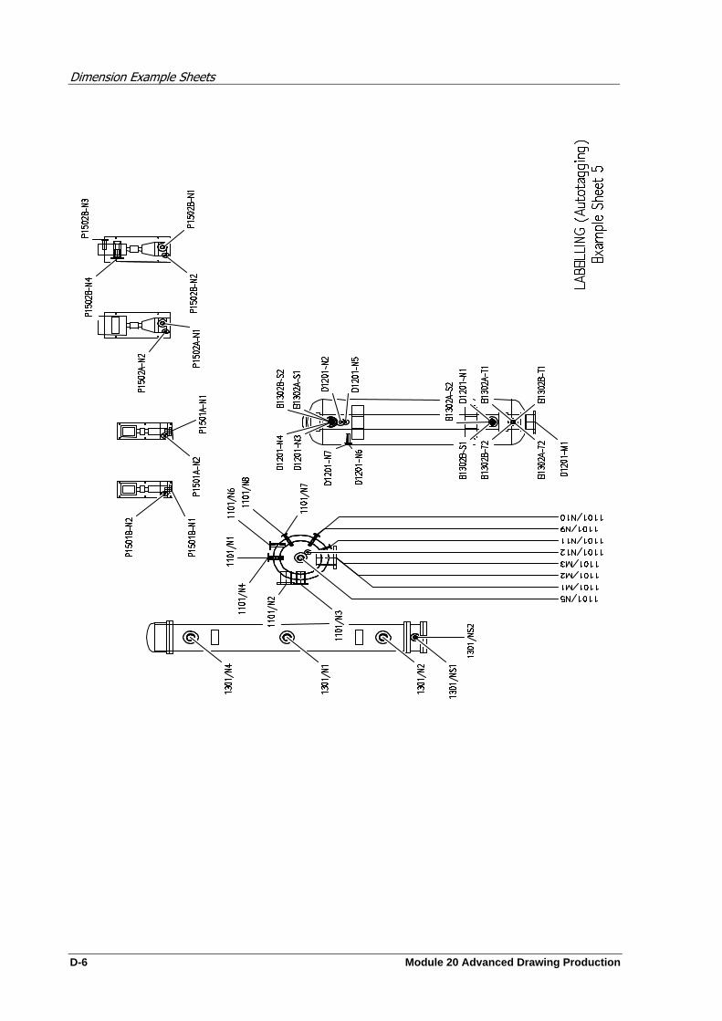
Dimension Example Sheets
D-6 Module 20 Advanced Drawing Production
Module 20 Advanced Drawing Production E-1
Section Example Sheets
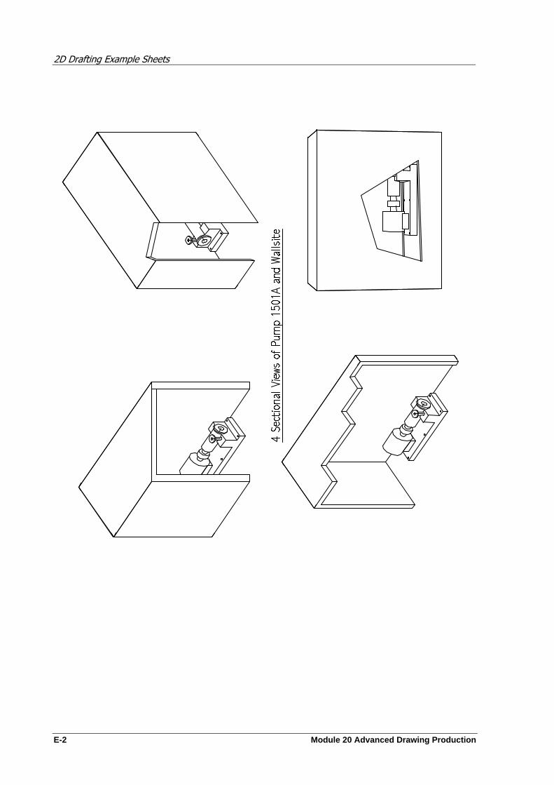
2D Drafting Example Sheets
E-2 Module 20 Advanced Drawing Production

Module 20 Advanced Drawing Production F-1
2D Drafting Example Sheets

2D Drafting Example Sheets
F-2 Module 20 Advanced Drawing Production