M2 Antenna Systems, Inc. Model No: KT36XA TRIBAND YAGI
20
SPECIFICATIONS MODEL NUMBER ............................................... KT36XA FREQ. RANGE .................................................... 14.0 - 14.35 MHz 21.0 - 21.45 MHz 28.0 - 29.0 MHz GAIN (Free Space) .............................................. SEE CHARTS FRONT TO BACK................................................ SEE CHARTS FEED IMPEDANCE / CONNECTOR .................. 50Ω / SO-239 VSWR .................................................................. <1.5:1 POWER HANDLING............................................ 3 kW BOOM LENGTH / DIAMETER............................. 32’ / 3” ELEMENT LENGTH ............................................ 25’ TURNING RADIUS .............................................. 21.5’ MAST SIZE .......................................................... 2” Nominal WIND AREA......................................................... 9.75 SQ. FT. WIND SURVIVAL ................................................ 100 MPH WEIGHT / SHIPPING WEIGHT........................... 80 lb. / 85 lb. 2 boxes FEATURES The M 2 KT36XA is the result of many hours spent on perfecting the original KLM KT-34XA through computer optimization confirmed by range and actual on-air tests. Five elements are active on 20 and 15 meters and all six are working on 10 meters! This is the hottest performing tribander on the market! A dual driven element (log cell) creates a rig pleasing, flat match, and broad gain & front to back curves across 10, 15, and 20m. A 3 kW 4:1 balun efficiently matches the antenna to 50Ω. All hardware has been upgraded to our machined shorting bars and rugged center element mounts. This is the strongest tribander on the market! We probably could have called it the “KB36XA” cuz it does! (“KB” = Kicks Butt). 10m f, MHz G, dBi G, dbd F/B 28.0 9.8 7.7 25 28.2 10.1 8.0 28 28.4 10.4 8.3 29 28.6 10.5 8.4 28 28.9 10.5 8.4 26 15m f, MHz G, dBi G, dbd F/B 21.0 9.2 7.1 19 21.1 9.3 7.2 22 21.2 9.4 7.3 24 21.3 9.5 7.4 24 21.4 9.6 7.5 23 20m f, MHz G, dBi G,dbd F/B 14.0 9.1 7.0 17 14.1 9.2 7.1 26 14.2 9.3 7.2 21 14.3 9.4 7.3 23 HIGH EFFICIENCY ELEMENT DESIGN, LARGE CONDUCTORS , HIGH Q CAPACITORS. 15M SERIES TUNED SHORTING BAR 3/4" TO 3/4" 1 x 72" SOE 3/8" TUBE 3/4" TUBE SHORTING BAR TUNES 10 METERS SHORTING BAR 10M CAPACITOR FULL SIZE ON 10 METERS 3/4 x 12" 3/4 SIZE ON 20 METERS 1/2" TIP 3/8" TUBE 15M CAPACITOR 15 METER SHORTING BAR FULL SIZE ON 15 METERS M2 Antenna Systems, Inc. 4402 N. Selland Ave. Fresno, CA 93722 Tel: (559) 432-8873 Fax: (559) 432-3059 Web: www.m2inc.com ©2011 M2 Antenna Systems Incoporated 9/28/11 Rev.01 M2 Antenna Systems, Inc. Model No: KT36XA TRIBAND YAGI
Transcript of M2 Antenna Systems, Inc. Model No: KT36XA TRIBAND YAGI

SPECIFICATIONS MODEL NUMBER ............................................... KT36XA FREQ. RANGE .................................................... 14.0 - 14.35 MHz 21.0 - 21.45 MHz 28.0 - 29.0 MHz GAIN (Free Space) .............................................. SEE CHARTS FRONT TO BACK................................................ SEE CHARTS FEED IMPEDANCE / CONNECTOR .................. 50Ω / SO-239 VSWR .................................................................. <1.5:1 POWER HANDLING............................................ 3 kW BOOM LENGTH / DIAMETER............................. 32’ / 3” ELEMENT LENGTH ............................................ 25’ TURNING RADIUS.............................................. 21.5’ MAST SIZE.......................................................... 2” Nominal WIND AREA......................................................... 9.75 SQ. FT. WIND SURVIVAL ................................................ 100 MPH WEIGHT / SHIPPING WEIGHT........................... 80 lb. / 85 lb. 2 boxes
FEATURES The M2 KT36XA is the result of many hours spent on perfecting the original KLM KT-34XA through computer optimization confirmed by range and actual on-air tests. Five elements are active on 20 and 15 meters and all six are working on 10 meters! This is the hottest performing tribander on the market! A dual driven element (log cell) creates a rig pleasing, flat match, and broad gain & front to back curves across 10, 15, and 20m. A 3 kW 4:1 balun efficiently matches the antenna to 50Ω. All hardware has been upgraded to our machined shorting bars and rugged center element mounts. This is the strongest tribander on the market! We probably could have called it the “KB36XA” cuz it does! (“KB” = Kicks Butt).
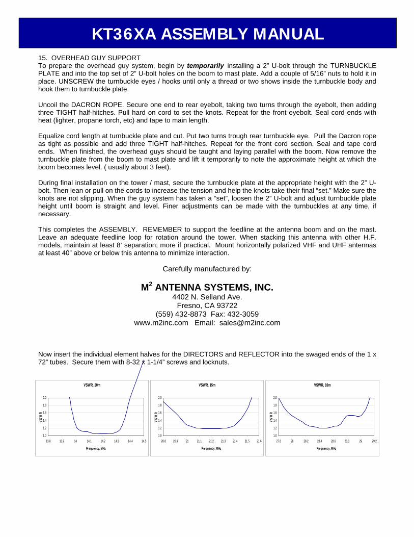
10m f, MHz G, dBi G, dbd F/B 28.0 9.8 7.7 25 28.2 10.1 8.0 28 28.4 10.4 8.3 29 28.6 10.5 8.4 28 28.9 10.5 8.4 26
15m f, MHz G, dBi G, dbd F/B 21.0 9.2 7.1 19 21.1 9.3 7.2 22 21.2 9.4 7.3 24 21.3 9.5 7.4 24 21.4 9.6 7.5 23
20m f, MHz G, dBi G,dbd F/B 14.0 9.1 7.0 17 14.1 9.2 7.1 26 14.2 9.3 7.2 21 14.3 9.4 7.3 23
HIGH EFFICIENCY ELEMENT DESIGN, LARGE CONDUCTORS , HIGH Q CAPACITORS.
15M SERIES TUNEDSHORTING BAR
3/4" TO 3/4"
1 x 72" SOE
3/8" TUBE
3/4" TUBE
SHORTING BARTUNES 10 METERS
SHORTING BAR
10M CAPACITOR
FULL SIZEON 10 METERS
3/4 x 12"
3/4 SIZEON 20 METERS
1/2" TIP
3/8" TUBE15M CAPACITOR
15 METERSHORTING BAR
FULL SIZEON 15 METERS
M2 Antenna Systems, Inc. 4402 N. Selland Ave. Fresno, CA 93722 Tel: (559) 432-8873 Fax: (559) 432-3059 Web: www.m2inc.com
©2011 M2 Antenna Systems Incoporated 9/28/11 Rev.01
M2 Antenna Systems, Inc. Model No: KT36XA TRIBAND YAGI

Tools: Phillips head screw driver, ‘green’, 11/32” nutdriver, 7/16” wrench, 7/16” socket, socket wrench, tape measure, and a friend. NOTE: To prevent galling of the stainless steel hardware, apply a light coating of Penetrox to all bolts and screws. The term ‘SWAGE’ refers to a physical reduction made in one diameter of tubing in order to fit into or over another. 1. SHORTING BARS Included with this kit are five different shorting bars, pictured in Figure 1. First locate the 10m shorting bars and shorting bar insulators (black or white). For each 10m shorting bar press a single shorting bar insulator into the large hole. This can be done initially with a vise or with a hammer and a block of wood. After the insulator has been partially set into the hole,
take two element clamp plates and center the shorting bar on top of the two plates. Now place the block of wood on top of the insulator and give a final strike. You should hear a snap. This is the indication that the insulator has been secured. Locate the small container of Penetrox and for each shorting bar, apply a light coating to the walls as indicated in the figure. Next install the 8-32 hardware listed to the right of each part into each respective shorting bar. Remember to apply a light coating of Penetrox to the threads of each screw. Finger tighten each locknut for now. 2. CAPACITOR TUBE ASSEMBLY There are three sizes of capacitor tubes. Tube sizes 8” and 10” are for the 10m capacitor while the 16” pieces are for 15m. Locate the shorter 3/4” diameter tubes and arrange them according to length. Also locate the bag of capacitor caps. As shown in Figure 2, starting with the 8” tube, lay a capacitor cap on a flat surface and with your own strength press one of the tube ends into the cap. Now slide on the shorting bar all the way to the cap, turn the tube over, and install another cap. Each capacitor cap will engage the 3/4” tube 3/8”(.375) so a measurement can be taken to insure complete engagement of the caps to the tube, simply measure between the inside edge of the two installed caps, it should be 5/8”(.625 to 3/4”(.750) shorter than the capacitor tube being
measured. Repeat this procedure for the 10” capacitor tube. For the 16” tubes follow the same procedure but slide on a different shorting bar as shown in the figure.
'T'-MATCH SHORTING BAR
15m SHORTING BAR
15m CAPACITOR TUBE SHORTING BAR
10m CAPACITOR TUBE SHORTING BAR
10m SHORTING BAR
8-32 x 1-1/4" SCREW (3) 8-32 X 1" SCREW (1)8-32 LOCKNUT (4)
8-32 x 1-1/2" SCREW (1)8-32 x 1" SCREW (1)8-32 LOCKNUT (2)
figure 1
8-32 x 1" SCREW (2) 8-32 LOCKNUT (2)
8-32 x 1-1/4" SCREW (2) 8-32 LOCKNUT (2)
8-32 x 1" SCREW (2) 8-32 LOCKNUT (2)
15M CAPACITOR TUBESHORTING BAR (10)
7-5/16" FOR 8" CAPS.9-5/16" FOR 10" CAPS.
3/4 x .049 x 8" STR (8)3/4 x .049 x 10" STR (2)
10M CAPACITORCAPACITOR CAPS (20) 10M CAPACITOR TUBESHORTING BAR (10)
15-5/16" FOR 16" CAPS.
15M CAPACITOR
KT36XA ASSEMBLY MANUAL
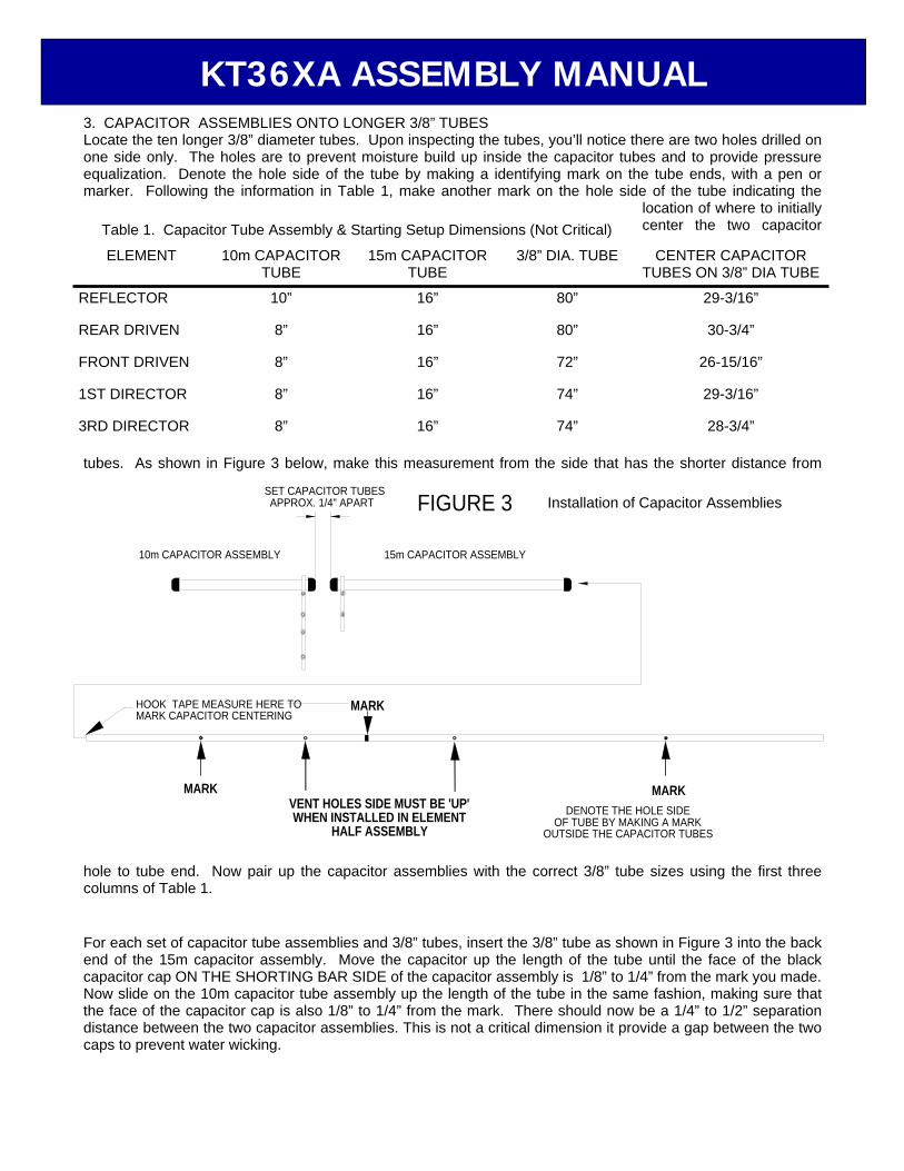
3. CAPACITOR ASSEMBLIES ONTO LONGER 3/8” TUBES Locate the ten longer 3/8” diameter tubes. Upon inspecting the tubes, you’ll notice there are two holes drilled on one side only. The holes are to prevent moisture build up inside the capacitor tubes and to provide pressure equalization. Denote the hole side of the tube by making a identifying mark on the tube ends, with a pen or marker. Following the information in Table 1, make another mark on the hole side of the tube indicating the
location of where to initially center the two capacitor
tubes. As shown in Figure 3 below, make this measurement from the side that has the shorter distance from
hole to tube end. Now pair up the capacitor assemblies with the correct 3/8” tube sizes using the first three columns of Table 1. For each set of capacitor tube assemblies and 3/8” tubes, insert the 3/8” tube as shown in Figure 3 into the back end of the 15m capacitor assembly. Move the capacitor up the length of the tube until the face of the black capacitor cap ON THE SHORTING BAR SIDE of the capacitor assembly is 1/8” to 1/4” from the mark you made. Now slide on the 10m capacitor tube assembly up the length of the tube in the same fashion, making sure that the face of the capacitor cap is also 1/8” to 1/4” from the mark. There should now be a 1/4” to 1/2” separation distance between the two capacitor assemblies. This is not a critical dimension it provide a gap between the two caps to prevent water wicking.
VENT HOLES SIDE MUST BE 'UP'WHEN INSTALLED IN ELEMENT
HALF ASSEMBLY
15m CAPACITOR ASSEMBLY
FIGURE 3
HOOK TAPE MEASURE HERE TOMARK CAPACITOR CENTERING
MARK
MARK
10m CAPACITOR ASSEMBLY
SET CAPACITOR TUBESAPPROX. 1/4" APART
DENOTE THE HOLE SIDEOF TUBE BY MAKING A MARK
OUTSIDE THE CAPACITOR TUBES
MARK
Installation of Capacitor Assemblies
ELEMENT 10m CAPACITOR TUBE
15m CAPACITOR TUBE
3/8” DIA. TUBE
CENTER CAPACITOR TUBES ON 3/8” DIA TUBE
REFLECTOR 10” 16” 80” 29-3/16”
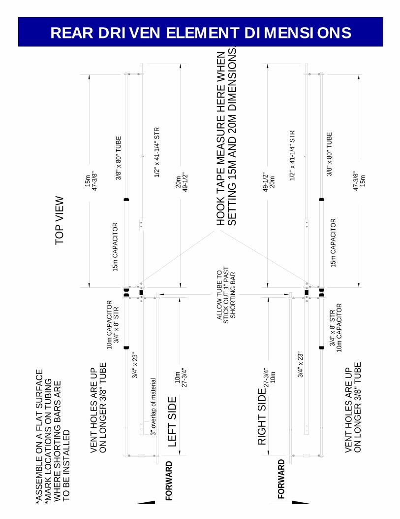
REAR DRIVEN 8” 16” 80” 30-3/4”
FRONT DRIVEN 8” 16” 72” 26-15/16”
1ST DIRECTOR 8” 16” 74” 29-3/16”
3RD DIRECTOR 8” 16” 74” 28-3/4”
Table 1. Capacitor Tube Assembly & Starting Setup Dimensions (Not Critical)
KT36XA ASSEMBLY MANUAL
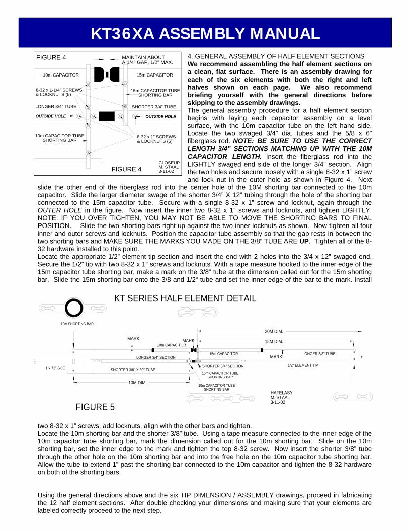
4. GENERAL ASSEMBLY OF HALF ELEMENT SECTIONS We recommend assembling the half element sections on a clean, flat surface. There is an assembly drawing for each of the six elements with both the right and left halves shown on each page. We also recommend briefing yourself with the general directions before skipping to the assembly drawings. The general assembly procedure for a half element section begins with laying each capacitor assembly on a level surface, with the 10m capacitor tube on the left hand side. Locate the two swaged 3/4” dia. tubes and the 5/8 x 6” fiberglass rod. NOTE: BE SURE TO USE THE CORRECT LENGTH 3/4” SECTIONS MATCHING UP WITH THE 10M CAPACITOR LENGTH. Insert the fiberglass rod into the LIGHTLY swaged end side of the longer 3/4” section. Align the two holes and secure loosely with a single 8-32 x 1” screw and lock nut in the outer hole as shown in Figure 4. Next
slide the other end of the fiberglass rod into the center hole of the 10M shorting bar connected to the 10m capacitor. Slide the larger diameter swage of the shorter 3/4” X 12” tubing through the hole of the shorting bar connected to the 15m capacitor tube. Secure with a single 8-32 x 1” screw and locknut, again through the OUTER HOLE in the figure. Now insert the inner two 8-32 x 1” screws and locknuts, and tighten LIGHTLY. NOTE: IF YOU OVER TIGHTEN, YOU MAY NOT BE ABLE TO MOVE THE SHORTING BARS TO FINAL POSITION. Slide the two shorting bars right up against the two inner locknuts as shown. Now tighten all four inner and outer screws and locknuts. Position the capacitor tube assembly so that the gap rests in between the two shorting bars and MAKE SURE THE MARKS YOU MADE ON THE 3/8” TUBE ARE UP. Tighten all of the 8-32 hardware installed to this point. Locate the appropriate 1/2” element tip section and insert the end with 2 holes into the 3/4 x 12” swaged end. Secure the 1/2” tip with two 8-32 x 1” screws and locknuts. With a tape measure hooked to the inner edge of the 15m capacitor tube shorting bar, make a mark on the 3/8” tube at the dimension called out for the 15m shorting bar. Slide the 15m shorting bar onto the 3/8 and 1/2“ tube and set the inner edge of the bar to the mark. Install
two 8-32 x 1” screws, add locknuts, align with the other bars and tighten. Locate the 10m shorting bar and the shorter 3/8” tube. Using a tape measure connected to the inner edge of the 10m capacitor tube shorting bar, mark the dimension called out for the 10m shorting bar. Slide on the 10m shorting bar, set the inner edge to the mark and tighten the top 8-32 screw. Now insert the shorter 3/8” tube through the other hole on the 10m shorting bar and into the free hole on the 10m capacitor tube shorting bar. Allow the tube to extend 1” past the shorting bar connected to the 10m capacitor and tighten the 8-32 hardware on both of the shorting bars. Using the general directions above and the six TIP DIMENSION / ASSEMBLY drawings, proceed in fabricating the 12 half element sections. After double checking your dimensions and making sure that your elements are labeled correctly proceed to the next step.
KT SERIES HALF ELEMENT DETAIL
SHORTER 3/4" SECTION
10m CAPACITOR TUBESHORTING BAR
15m CAPACITOR TUBESHORTING BAR
SHORTER 3/8" X 30" TUBE
FIGURE 5
1 x 72" SOE
10M DIM.
LONGER 3/4" SECTION
10m SHORTING BAR
10m CAPACITORMARK MARK
1/2" ELEMENT TIP
HAFELASYM. STAAL3-11-02
15m CAPACITORMARK
LONGER 3/8" TUBE
15M DIM.
20M DIM.
OUTSIDE HOLE
10m CAPACITOR TUBESHORTING BAR
8-32 x 1-1/4" SCREWS& LOCKNUTS (5)
LONGER 3/4" TUBE
10m CAPACITOR
FIGURE 4
OUTSIDE HOLE
8-32 x 1" SCREWS& LOCKNUTS (5)
FIGURE 4CLOSEUPM. STAAL3-11-02
15m CAPACITOR TUBESHORTING BAR
SHORTER 3/4" TUBE
MAINTAIN ABOUTA 1/4" GAP, 1/2" MAX.
15m CAPACITOR
KT36XA ASSEMBLY MANUAL

5. HF CLAMP PLATE PAIR ASSEMBLY Locate the 11 element clamp plates, the Balun ‘L’-Bracket, 2-1/2” U-bolt & Saddle, and element clamp cap. Assemble the plates into six pairs with the radii facing each other using four 1/4-20 x 2” bolts. On one of the ‘alike’-pair combinations, attach the Balun ‘L’-Bracket to the outside clamp plate with the flat side up and higher than the plates. Install the 2-1/2” U-bolt & Saddle combination on the top side of the ‘L’-Bracket and secure with 5/16” nuts and lockwashers. This assembly will be used for the FRONT DRIVEN ELEMENT. Finger tighten all the hardware. The ‘oddball’ plate combination of element clamp plate and smaller clamp cap, will be used for DIRECTOR #2. 6. FRONT AND REAR DRIVEN ELEMENT ASSEMBLY Take the element clamp plate pair assembly for the FRONT DRIVEN ELEMENT (previous step) and one of the ‘alike’ element clamp pairs, and for both insert a 7/8 x 14-3/4” fiberglass rod through the plates. Orient the four holes up and make sure the rod is centered. Tighten the four bolts evenly on the clamp plates. Locate the four 7/8” poly disc insulators. Slide a poly disc onto both ends of each 7/8” fiberglass rod and position them right up against the element clamp plates. If the discs won’t fit onto the rod, try soaking them in HOT water for a few minutes. Locate four of the 1 x 72” SOE (swaged one end) tubes. Select two to be used for the FRONT DRIVEN ELEMENT. Locate the two ‘T’-match shorting bars and slide one onto each of the straight ends of the 1” tubes you have selected. The other pair of 1 x 72” SOE tubes will be for the REAR DRIVEN ELEMENT. For all four 1” tubes, slide the straight ends on both sides of the two fiberglass rods. Align the holes, insert two 1/4-20 x 2” bolts up through the bottom, and temporarily lay the two assemblies flat. Locate the eight 3/8” clamp blocks. Spread a little Penetrox on each clamp block face. Slide two clamp blocks with their faces towards one another onto the 1/4-20 bolt posts on each element assembly and thread on the 1/4-20 locknuts. Do not tighten the locknuts at this time. Paying close attention to the DIMENSION SHEET, insert the individual element halves for the FRONT and REAR DRIVEN ELEMENTS into the swaged ends of the 1 x 72” tubes. Secure them with 8-32 x 1-1/4” screws and locknuts. Make sure the flat part of the ‘L’-Bracket is pointed in the same direction as the
capacitor tube sides of the FRONT DRIVEN ELEMENT halves. 7. REFLECTOR, DIRECTOR #1, AND DIRECTOR #3 ASSEMBLY Locate the remaining six 1 x 72” SOE (swaged one end) tube sections and the three 7/8 x 36” aluminum center sleeves. With the three remaining pairs of ‘alike’ element clamp plates, insert a 7/8” center sleeve and slide a 1 x 72” tube section onto both sides of the sleeve. Align the two holes and secure with 1/4-20 x 1-1/2” bolts and locknuts. Orient the tubes so that the locknuts are down and centered. Tighten the 1/4-20 hardware evenly. A 1” gap between the two tube sections is normal. 8. DIRECTOR #2 ASSEMBLY Locate the 1 x 20” SBE (swaged both ends) center support tube and insert this piece between the plates of the remaining
‘oddball’ element clamp assembly. Orient the tube holes up, center the tube, and tighten the 1/4-20 hardware. Now insert the two 3/4 x 48” SOE tubes into both ends of the center support tube and secure with 8-32 x 1-1/4” screws and locknuts. Add the 1/2” element tip sections to the 3/4” tubes, securing them with 8-32 x 1” screws and locknuts. 9. BOOM ASSEMBLY Prior to assembling the boom, inspect each mating surface and holes for any metal chips or burrs. Apply a light coating of PENETROX to the swaged ends of each piece. Using the DIMENSION SHEET as a guide, lay out the five 3” pieces as shown. Note that the single straight section is the FRONT end of the antenna. Now assemble the boom and secure the pieces together with 1/4-20 x 3-1/2” bolts and locknuts. Next insert the two 3/8 x 6” eyebolts through the holes at both ends of the boom. Secure them with 3/8” nuts and lockwashers.
SADDLE CLAMPS PER ELEMENT (2)
ELEMENT CLAMP DETAILFIGURE 6
FOR REFLECTOR, AND DIRECTOR(S)
ELEMENT CLAMP PLATESPER ELEMENT (2)
1/4-20 x 3" BOLTSPER ELEMENT (4)
1" x 72" SOE
7/8" x 36" INSIDE SLEEVE
KT36XA ASSEMBLY MANUAL

10. ELEMENT INSTALLATION We advise that you elevate the antenna boom onto a couple of sawhorses or bucks for the remaining assembly steps. Use the DIMENSION SHEET as a guide to properly install the six elements onto the boom. If you have not labeled which side of the element faces towards the front of the antenna, you will want to pay close attention to the DIMENSION SHEET. In fact, you might want to label them now. You also might want to have a friend handy to keep the antenna from moving on you. Place the REFLECTOR ELEMENT onto the boom in the orientation shown on the DIMENSION SHEET. Set the outside edge of the element clamp plate 2-1/2” from the rear of the boom. Locate two 3” saddles and insert two 1/4-20 x 3” bolts through each of the holes. Next attach the two saddles to the underside of the element clamp plates, and lightly tighten the entire assembly, so the element won’t move. Using a tape measure hooked to the outside edge of the clamp plate facing the rear, mark off the location for the outside edge of the element clamp on the REAR DRIVEN ELEMENT assembly with a marking pen or pencil. Install the REAR DRIVEN ELEMENT as you did for the REFLECTOR. BE CAREFUL! This element is not installed in the same orientation. Make sure you follow the element placement on the DIMENSION SHEET. Continue installing the rest of the elements in the same fashion. Since the 2nd director only has one element clamp plate, it requires just a single 3” saddle. Also take note that this element can be placed on the boom with the clamp cap facing either the FRONT or REAR of the antenna. After all of the elements have been installed take a couple of steps back and look down from the end of the antenna. Check to see if the elements are lined up with one another. If any need to be fixed, simply loosen the saddles, straighten, and re-tighten. 11. INSTALLATION OF PHASING LINES Locate the two 3/8” tube phasing lines, the phasing line insulator, and one cable tie. Insert both tubes into the two holes on the insulator. Temporarily loosen the 1/4-20 locknuts located on the FRONT and REAR DRIVEN ELEMENTS and slide the two phasing lines into the one of the 3/8” clamp block sets. Allow the ends of the phasing lines to stick out 4” past the ends of the clamp blocks. Now pull the phasing lines back, guiding them into the clamp block set on the other driven element. Now re-tighten the four 1/4-20 locknuts. Set the insulator about midway between the two elements and secure it with large nylon tie inserted through the bottom hole and around the boom. 12. BALUN INSTALLATION Refer to the figures on DUAL DRIVEN AND T-MATCH ASSEMBLY for this procedure. Loosen the 2-1/2” U-bolt on the L-bracket and insert the 4:1 HF Balun with the connector facing towards the front of the antenna. Position the Balun so that the U-bolt hits the edge of the front cap. Now tighten the U-bolt just enough to hold firmly in place. BE CAREFUL! Overtightening might crack the case of the Balun. On each of the mounting posts on the balun attach the balun straps (shorter side). 13. ‘T’-MATCH INSTALLATION Refer to the figures on DUAL DRIVEN AND T-MATCH ASSEMBLY for this procedure. Locate the two 1/2 x 23-1/2” ‘T’-Feed tubes and 3/8 x 10” fiberglass insulator. Install the 3/8” fiberglass insulator into one of the 1/2” ‘T’-feed tubes. Align the holes and temporarily secure with a 8-32 x 1” screw. Now feed the undrilled ends of both ‘T’-feed tubes into the two ‘T’-match shorting bars. Slide one of them back so you can install the other end of the 3/8” fiberglass rod into the other 1/2” tube. Align the holes and secure with another 8-32 x 1” screw. With all of the hardware loose, rotate the entire ‘T’-Match assembly up so that the two 8-32 screws fit right into the two Balun straps. Secure the two 8-32 screws with two 8-32 locknuts. Make sure there is ample room to connect your feedline to the balun. Now set the two shorting bars to the dimensions shown on the DIMENSION SHEET and tighten all the hardware. 14. BOOM TO MAST PLATE INSTALLATION Locate the boom to mast plate, 3” U-bolts & saddles, and 2” U-bolts & saddles. Install the four 2” U-bolts on one side of the boom to mast plate. Center the plate at the location shown on the DIMENSION SHEET, and install it using the 3” U-bolts, saddles, 3/8” nuts, and lockwashers. If possible, attach the feedline to the balun and route it forward to about 18 feet from the rear of the boom. Seal the connector with black tape, coax seal or equivalent. A 3” U-bolt pattern exists should you need to mount the antenna to a 3” mast.
KT36XA ASSEMBLY MANUAL
15. OVERHEAD GUY SUPPORT To prepare the overhead guy system, begin by temporarily installing a 2” U-bolt through the TURNBUCKLE PLATE and into the top set of 2” U-bolt holes on the boom to mast plate. Add a couple of 5/16” nuts to hold it in place. UNSCREW the turnbuckle eyes / hooks until only a thread or two shows inside the turnbuckle body and hook them to turnbuckle plate. Uncoil the DACRON ROPE. Secure one end to rear eyebolt, taking two turns through the eyebolt, then adding three TIGHT half-hitches. Pull hard on cord to set the knots. Repeat for the front eyebolt. Seal cord ends with heat (lighter, propane torch, etc) and tape to main length. Equalize cord length at turnbuckle plate and cut. Put two turns trough rear turnbuckle eye. Pull the Dacron rope as tight as possible and add three TIGHT half-hitches. Repeat for the front cord section. Seal and tape cord ends. When finished, the overhead guys should be taught and laying parallel with the boom. Now remove the turnbuckle plate from the boom to mast plate and lift it temporarily to note the approximate height at which the boom becomes level. ( usually about 3 feet). During final installation on the tower / mast, secure the turnbuckle plate at the appropriate height with the 2” U-bolt. Then lean or pull on the cords to increase the tension and help the knots take their final “set.” Make sure the knots are not slipping. When the guy system has taken a “set”, loosen the 2” U-bolt and adjust turnbuckle plate height until boom is straight and level. Finer adjustments can be made with the turnbuckles at any time, if necessary. This completes the ASSEMBLY. REMEMBER to support the feedline at the antenna boom and on the mast. Leave an adequate feedline loop for rotation around the tower. When stacking this antenna with other H.F. models, maintain at least 8’ separation; more if practical. Mount horizontally polarized VHF and UHF antennas at least 40” above or below this antenna to minimize interaction.
Carefully manufactured by:
M2 ANTENNA SYSTEMS, INC. 4402 N. Selland Ave.
Fresno, CA 93722 (559) 432-8873 Fax: 432-3059
www.m2inc.com Email: [email protected] Now insert the individual element halves for the DIRECTORS and REFLECTOR into the swaged ends of the 1 x 72” tubes. Secure them with 8-32 x 1-1/4” screws and locknuts.
VSWR, 20m
1.0
1.2
1.4
1.6
1.8
2.0
13.8 13.9 14 14.1 14.2 14.3 14.4 14.5
Frequency, MHz
VSW
R
VSWR, 15m
1.0
1.2
1.4
1.6
1.8
2.0
20.8 20.9 21 21.1 21.2 21.3 21.4 21.5 21.6
Frequency, MHz
VSW
R
VSWR, 10m
1.0
1.2
1.4
1.6
1.8
2.0
27.8 28 28.2 28.4 28.6 28.8 29 29.2
Frequency, MHz
VSW
R
KT36XA ASSEMBLY MANUAL

1 0m
CAP
A CIT
OR
TUBE
SHO
RTIN
G B
AR
15m
CAP
ACIT
OR
T UBE
S HO
RTIN
G B
AR
SHO
RTER
3/8
" TUB
E
ASSE
MBL
E E L
EMEN
T HA
LVES
ON
A CL
E AN,
FLA
T SU
RFAC
E
8 -32
x 1
-1/4
" SCR
EWS
& LO
CKNU
TS (2
)
10m
SHO
RTIN
G B
A R
1" x
72"
SO
E
1 0m
CAP
A CIT
OR
LONG
ER 3
/4" S
ECTI
ON
APPL
Y A
LIG H
T CO
A TIN
G OF
PE
NET R
OX T
O AL
L ME
TALL
IC
MATI
NG S
U RFA
CES
INCL
UDIN
G S C
REW
S
HOLE
S IN
LO
N GER
3/
8 " T
UBE
ARE
UP
8-32
x 1
" SCR
EWS
& LO
CKNU
TS (2
)
1/2"
ELE
MEN
T TI
P
15m
CAP
ACIT
OR
S HO
RTER
3/4
" SEC
T IO
N
LONG
ER 3
/8" T
UBE
TERM
S:
STR:
STR
AIG H
T PI
ECE
OF T
U BIN
GSO
E: S
WAG
ED O
NE E
N DSB
E: S
WAG
ED B
OTH
ENDS
SWAG
E: A
PH Y
SICA
L RE
DUC T
ION
MADE
IN
ONE
DIA
MET
ER O
F TU
BIN G
IN
ORD
ER T
O FI
T O V
ER.
1 . L
AY C
A PAC
ITO
R AS
SEM
B LY
ON
FLAT
SUR
FACE
2. I
NSTA
LL 3
/4" S
OE
TUB E
SEC
TIO
NS
3. A
SSE M
BLE
AND
SECU
R E IN
NER
8-32
HAR
DWAR
E
4. I
N STA
LL &
SET
15m
SHO
RTIN
G B
AR T
O S
PECI
FIED
DIM
ENSI
ONS
O
N L O
NGER
3/8
" TUB
E
5. I
N STA
LL 1
/ 2" E
LEM
E NT
TIP
6. I
NSTA
LL &
SET
10m
SHO
RTIN
G B
AR T
O S
PECI
FIE D
DIM
ENS I
ONS
O
N LO
NGE R
3/8
" TU B
E
7. I
NSTA
L L S
HORT
ER 3
/8" T
UBE
SEC T
ION
INTO
10m
SHO
RTIN
G
BAR
AND
10m
CAP
A CIT
OR
S HO
RTIN
G B
AR
8. W
ITH
A M
ARKE
R , L
ABEL
THE
ELE
MEN
T BY
I TS
NAM
E , S
IDE,
AN D
IND
ICAT
E IT
S O
RIE N
TATI
ON
WIT
H RE
S PEC
T TO
FRO
NT O
F AN
TEN N
A
GEN
E RAL
ASS
EMBL
Y
8-32
x 1
-1/4
" SCR
E WS
& LO
CKNU
TS (5
)
10m
CAP
ACIT
OR
LONG
ER 3
/4" T
U BE
10m
CA P
ACIT
OR
T UBE
SHO
RTIN
G B
AR
O UTS
IDE
HOLE
1/4"
- 1/
2" M
AX.
15m
CAP
ACIT
OR
15m
CAP
A CIT
OR
TUB E
SHO
RTIN
G B
AR
8-32
x 1
" SCR
E WS
& LO
CKN U
TS (5
)
OUTS
IDE
HOLE
KT36XA-HALF ELEMEN-GENERAL ASSEMBLY

RIG
H T S
I DE
VEN T
HO
L ES
ARE
UPO
N LO
N GER
3/8
" TU B
E
*AS S
EMB L
E O
N A
FLAT
SU R
FAC E
*MA R
K LO
CATI
ONS
ON
TUBI
NG W
HER E
SHO
RTIN
G B
ARS
ARE
TO
BE
INST
A LLE
D 3" o
verla
p of
mat
eria
l
FORW
ARD
10m
CAP
A CIT
OR
3 /4"
x 1
0 " S
TR
3/4"
x 2
1"
10m
27-1
/4"
3/8"
x 8
0" T
UBE
1/2"
x 5
1-1/
4" S
TR
TOP
VIEW
15m
48-3
/8"
15m
CAP
A CIT
OR
2 0m
59-1
/2"
A LLO
W T
UBE
TOST
I CK
OUT
1" P
AST
S HO
RTIN
G B
AR
L EFT
SID
E
V ENT
HO
LES
ARE
UPO
N LO
NGER
3/8
" TUB
E
FORW
ARD
2 7-1
/4"
10m
3/4"
x 1
0" S
TR1 0
m C
APAC
ITO
R
3/4"
x 2
1"
HOO
K TA
PE M
EAS U
RE H
ERE
WH E
N SE
T TIN
G 1
5M A
N D 2
0M D
IMEN
S IO
NS.
1/2"
x 5
1 -1/
4" S
T R
3/8"
x 8
0" T
UBE
59-1
/2"
20m
15m
CAP
ACIT
OR
4 8-3
/8"
15m
KT36XA ASSEMBLY MANUAL
VEN
T H
OLE
S AR
E U
PO
N L
ON
GER
3/8
" TU
BE
*AS S
EMB L
E O
N A
FL A
T S U
RFA
CE
*MA R
K LO
CAT
ION
S O
N T
UBI
NG
WH
ERE
SHO
RTI
NG
BA R
S AR
E T
O B
E IN
STAL
LED 3"
ov e
rlap
of m
ater
ial
LEFT
SID
EFO
RWA R
D
10m
CAP
ACIT
OR
3/4"
x 8
" STR
3/4"
x 2
3"
10m
27-3
/4"
3/8"
x 8
0" T
UBE
1/2"
x 4
1-1/
4" S
TR
TOP
VIE W
1 5m
47-3
/8"
15m
CAP
ACIT
OR
2 0m
49- 1
/2"
ALLO
W T
UBE
T OST
ICK
OUT
1" P
AST
SHO
RTIN
G B
AR
VEN
T H
OL E
S AR
E U
PO
N L
ON
GE R
3/8
" TU
B E
RIG
H T S
I DE
FORW
ARD
27-3
/4"
10m
3/4"
x 8
" STR
1 0m
CAP
ACIT
OR
3/4"
x 2
3"
HOO
K TA
PE M
EAS U
RE H
ERE
WH E
N S E
TTIN
G 1
5M A
ND 2
0M D
IMEN
SIO
NS.
1/2"
x 4
1-1/
4 " S
TR
3 /8"
x 8
0 " T
UBE
4 9-1
/2"
20m
15m
CAP
ACIT
OR
47- 3
/8"
15m
REAR DRIVEN ELEMENT DIMENSIONS
RIG
HT S
IDE
VENT
HO
LES
ARE
U PO
N LO
NGER
3/8
" TUB
E
*AS S
EMB L
E O
N A
FLAT
SUR
FACE
*MA R
K LO
CAT I
ONS
ON
TUBI
NG W
HER E
SHO
RTIN
G B
A RS
ARE
TO
BE
INST
ALLE
D 3" o
v erla
p of
mat
eria
l
FORW
A RD
10m
CAP
ACIT
OR
3/4"
x 8
" STR
3/4"
x 2
1"
10m
25-1
/4"
3/8"
x 7
2" T
UBE
1/2"
x 3
7-1/
4" S
TR
TOP
VIE W
1 5m
43-1
/4"
15m
CAP
ACIT
OR
2 0m
45- 1
/2"
ALLO
W T
UBE
T OST
ICK
OUT
1" P
AST
SHO
RTIN
G B
AR
VEN T
HO
L ES
ARE
UPO
N L O
NGE R
3/8
" TUB
E
LEFT
SID
E
FORW
ARD
25-1
/4"
10m
3/4"
x 8
" STR
1 0m
CAP
ACIT
OR
3/4"
x 2
1"
HOO
K TA
PE M
EAS U
RE H
ERE
WH E
N S E
TTIN
G 1
5M A
ND 2
0M D
IMEN
SIO
NS.
1/2"
x 3
7-1/
4 " S
TR
3 /8"
x 7
2 " T
UBE
4 5-1
/2"
20m
15m
CAP
ACIT
OR
43- 1
/4"
15m
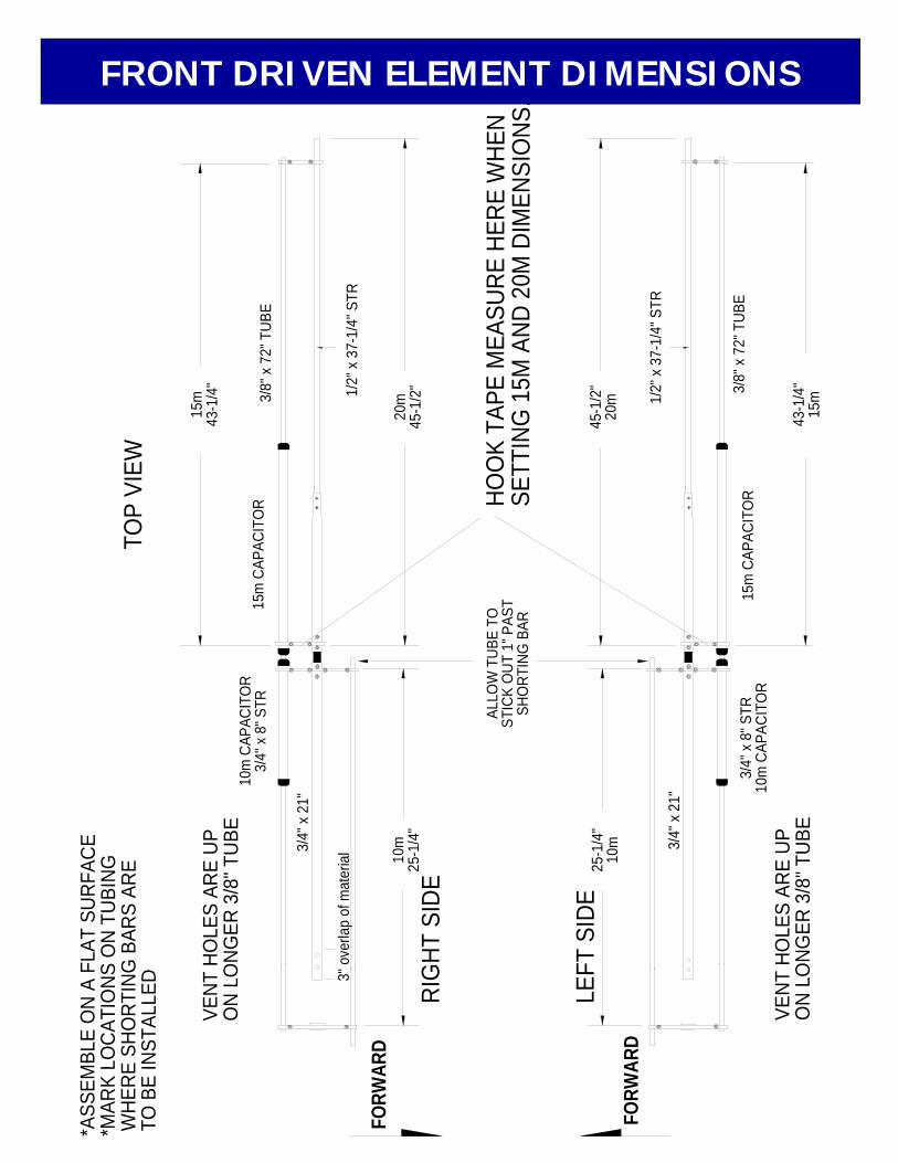
FRONT DRIVEN ELEMENT DIMENSIONS

VENT
HO
LES
ARE
U PO
N LO
NGER
3/8
" TUB
E
*AS S
EMB L
E O
N A
FLAT
SUR
FACE
*MA R
K LO
CAT I
ONS
ON
TUBI
NG W
HER E
SHO
RTIN
G B
A RS
ARE
TO
BE
INST
ALLE
D 3" o
v erla
p of
mat
eria
l
LEFT
SID
EFO
RWA R
D
10m
CAP
ACIT
OR
3/4"
x 8
" STR
3/4"
x 2
3"
10m
27"
3/8"
x 7
4" T
UBE
1/2"
x 4
4-3/
4" S
TR
TOP
VIE W
1 5m
43"
15m
CAP
ACIT
OR
2 0m
53"
ALLO
W T
UBE
T OST
ICK
OUT
1" P
AST
SHO
RTIN
G B
AR
VEN T
HO
L ES
ARE
UPO
N L O
NGE R
3/8
" TUB
E
RIG
HT S
IDE
FORW
ARD
27"
10m
3/4"
x 8
" STR
1 0m
CAP
ACIT
OR
3/4"
x 2
3"
HOO
K TA
PE M
EAS U
RE H
ERE
WH E
N S E
TTIN
G 1
5M A
ND 2
0M D
IMEN
SIO
NS.
1/2"
x 4
4-3/
4 " S
TR
3 /8"
x 7
4 " T
UBE
5 3"
20m
15m
CAP
ACIT
OR
43"
15m
1ST DIRECTOR ELEMENT DIMENSION

96.1
25" H
ALF
LENG
TH
ELEM
E NT
CLA M
P PL
A TE
(1)
8 -32
x 1
" SCR
EWS
& LO
CKNU
TS P
ER S
IDE
(2)
8 -32
x 1
-1/4
" SCR
EWS
& LO
CKNU
TS P
ER S
IDE
(2)
1 x
2 0" S
BE
3/4 "
x 4
8" S
OET O
P V I
EW
1/2"
x 4
1-1/
8" E
XPO
SED
F RON
T OF
ANT
ENNA
RIG
HT S
IDE
1" x
20"
SBE
1/4-
2 0 x
3" B
OLT
S ( 2
)
ELE M
ENT
C LAM
P CA
P (1
)
1/4-
20 x
2" B
OLT
S &
LOCK
NUT S
(4)
S ADD
LE C
LAM
P (1
)
2ND DIRECTOR ELEMENT DIMENSION
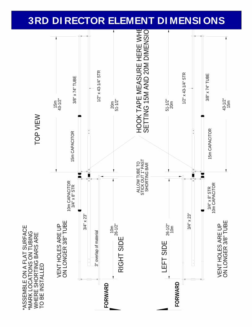
RIG
HT S
IDE
VENT
HO
LES
ARE
U PO
N LO
NGER
3/8
" TUB
E
*AS S
EMB L
E O
N A
FLAT
SUR
FACE
*MA R
K LO
CAT I
ONS
ON
TUBI
NG W
HER E
SHO
RTIN
G B
A RS
ARE
TO
BE
INST
ALLE
D 3" o
v erla
p of
mat
eria
l
FORW
A RD
10m
CAP
ACIT
OR
3/4"
x 8
" STR
3/4"
x 2
3"
10m
26-1
/2"
3/8"
x 7
4" T
UBE
1/2"
x 4
3-1/
4" S
TR
TOP
VIE W
1 5m
43-1
/2"
15m
CAP
ACIT
OR
2 0m
51- 1
/2"
ALLO
W T
UBE
T OST
ICK
OUT
1" P
AST
SHO
RTIN
G B
AR
VEN T
HO
L ES
ARE
UPO
N L O
NGE R
3/8
" TUB
E
LEFT
SID
E
FORW
ARD
26-1
/2"
10m
3/4"
x 8
" STR
1 0m
CAP
ACIT
OR
3/4"
x 2
3"
HOO
K TA
PE M
EAS U
RE H
ERE
WH E
N S E
TTIN
G 1
5M A
ND 2
0M D
IMEN
SIO
NS.
1/2"
x 4
3-1/
4 " S
TR
3 /8"
x 7
4 " T
UBE
5 1-1
/2"
20m
15m
CAP
ACIT
OR
43- 1
/2"
15m
3RD DIRECTOR ELEMENT DIMENSIONS

FRONT DRIVEN ELEMENT
3/8" PHASING LINES (2)
3/8" CLAMP BLOCKS PER ELEMENT (4)
8-32 x 1-1/2" SCREW& LOCKNUT
8-32 x 1" SCREW & LOCKNUT
1/4-20 x 3" BOLTSPER ELEMENT (4)
2-1/2" U-BOLT & SADDLE (1)5/16" NUT (2) & LOCKWASHER (2)
4:1 HF BALUN
REAR DRIVEN ELEMENT
1/4-20 x 3-1/2" BOLTS& LOCKNUTS
8 PLACES ON BOOMPHASING LINE
INSULATOR& CABLE TIE
7/8" x 14-3/4" FIBERGLASS RODPER DRIVEN ELEMENT (1)
'T'-FEED TUBES (2)3/8" x 10" FIBERGLASS ROD (1)
1/4-20 x 2" BOLTSPER ELEMENT (4)
SADDLE CLAMPSPER ELEMENT (2)
HF CLAMP PLATESPER ELEMENT (2)
1/4-20 x 2" BOLTSPER ELEMENT (2)
BALUN STRAP (2)8-32 x 1" SCREW (2)& LOCKNUT (2)
'T'-MATCH SHORTING BAR (2)
POLYDISK INSULATORS PER DRIVEN
ELEMENT ASSEMBLY (2)FRONT
OF ANTENNA
BALUN 'L'-BRACKET (1)
DUAL DRIVEN AND T-MATCH ASSEMBLIES

SHORTING BAR DIMENSIONS AREMEASURED FROM SO-239 CONNECTOR
TO INSIDE EDGE OF SHORTING BAR
TERMS: STR: STRAIGHT PIECE OF TUBINGSOE: SWAGED ONE ENDSBE: SWAGED BOTH ENDSSWAGE: A PHYSICAL REDUCTION MADE IN ONE DIAMETER OF TUBING IN ORDER TO FIT INSIDE OR OVER ANOTHER.
TO PREVENT GALLING OF THE STAINLESS STEEL HARDWARE, APPLY A LIGHT COATING
OF PENETROX TO THE THREADS OF ALL BOLTS AND SCREWS
NOTE THAT ORIENTATIONOF THE ELEMENT HALVES
VARY FROM ONE ANOTHER
USE THE INDIVIDUALASSEMBLY DRAWINGS
TO BUILD ELEMENT HALVES
OTHER HALF SECTIONSREMOVED FOR CLARITY
3" x
9 5" S
OE
3/8 x 6" EYEBOLT3/8" NUT & LOCKWASHER
3" x
28" S
T R
FRONT
388
354
360
98
270
95
3" x
9 5" S
OE
1/4-20 x 3-1/2" BOLTS & LOCKNUTS8 PLACES
23"
PHASING LINEINSULATOR
BOOM TO MAST PLATECENTERED APPROXMATELY
8" FROM JOINT
PHASING LINES
3" x
95" S
OE
180
59172
90
55
7/8" X 30" INNER SLEEVE SECTION
3/8" x 6" EYEBOLT3/8" NUT & LOCKWASHER
1" X 72" SOE ELEMENT BUTT
POSITION OUTSIDE EDGE OFREFLECTOR HF CLAMP 2.5"
FROM REAR EDGE OF BOOM
36
74
3" x
95" S
OE
ELEMENT SPACINGS CENTER TO CENTER
0.0REAR
DIRECTOR #1
15m43-1/2"
20m51-1/2"
10m26-1/2"
3/4" x 20"Exposed
DIRECTOR #3
2" U-BOLT, SADDLE,5/16-18 NUTS (2)& LOCKWASHERS (2)
2" MAST TURNBUCKLE HARDWARE DETAIL
TURNBUCKLE PLATE
3/8" TURNBUCKLES (2)
15m43.0"
DIRECTOR #2
FRONT DRIVEN20m
45-1/2"
15m47-3/8"
15m43-1/4"
20m53.0"
3/4" x 20"Exposed
10m27.0"
3/4" x 18"Exposed
10m25-1/4"
REAR DRIVEN
20m59-1/2"
20m49-1/2"
10m27-1/4"
10m27-3/4"
3/4" x 20"Exposed
3/4" x 18"Exposed 15m
48-3/8"
REFLECTOR
KT36XA DIMENSION SHEET

DESCRIPTION .................................................................... QTY Boom sections, 3" x .065” x 95” swaged.............................. 4 Boom section, 3” x .065” x 28” straight ................................ 1 Center sleeve, 7/8” x .058” x 36” STR ................................. 3 Center Support Tube, 1” x .058” x 20” SBE......................... 1 Element, 1” x .058” x 72" SOE............................................. 10 Element, 3/4” x .049” x 48” SOE.......................................... 2 Element, 3/4” x .049” x 23" SOE.......................................... 6 Element, 3/4 x .049 x 21” SOE ............................................ 4 Element, 3/4” x .049 x 12” SBE ........................................... 10 Capacitor tube, 3/4” x .049” x 8” alum. tube STR ................ 8 Capacitor tube, 3/4” x .049” x 10” alum. tube STR .............. 2 Capacitor tube, 3/4” x .049” x 16” alum. tube STR .............. 10 Element, 1/2” x .049”
x 51-1/4”................................................ 2 x 44-3/4”................................................ 2 x 44-1/8”................................................ 2 x 43-1/4”................................................ 2 x 41-1/4”................................................ 2 x 37-1/4”................................................ 2
'T'-Feed Tubes 1/2” x .049” x 23-1/2" ................................ 2 Linear Loading Tube, 3/8” x .049” x 80”............................... 4 Linear Loading Tube, 3/8” x .049” x 74”............................... 4 Linear Loading Tube, 3/8” x .049” x 72”............................... 2 Phasing Line Tube, 3/8” x .049” x 57”.................................. 2 Linear Loading Tube, 3/8” x .049” x 30”............................... 10 Fiberglass insulator, 5/8” x 6” rod ........................................ 10 Fiberglass insulator, 7/8” x 14-3/4” rod ................................ 2 Boom to mast plate, 1/4” x 8” x 6" ....................................... 1 Balun, HF, 4:1...................................................................... 1 Dacron rope, black 5/16” x 30 ft........................................... 1 Cable ties, nylon, large ........................................................ 3 Penetrox cup........................................................................ 1 Assembly Manual ................................................................ 1 IN BAG #1 Turnbuckle, 3/8"................................................................... 2 Eyebolt, 3/8” x 6" ................................................................. 2 IN BAG #2 U-bolt & saddle, 3"............................................................... 2 IN BAG #3 U-bolt & saddle, 2-1/2" standard.......................................... 1 U-bolt & saddle, 2" standard................................................ 5 IN BAG #4 Element Clamp Plate, 3/8" x 2-1/2” x 4”............................... 11 Element Clamp Cap, Small HF............................................ 1 IN BAG #5 Saddle clamp, 1/2" x 1” x 4”................................................. 11
KT36XA PARTS & HARDWARE
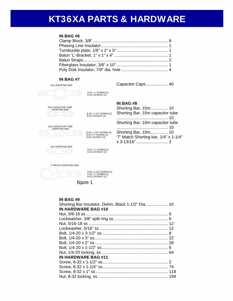
IN BAG #6 Clamp Block, 3/8” ................................................................ 8 Phasing Line Insulator ......................................................... 1 Turnbuckle plate, 1/8” x 2” x 5" ............................................ 1 Balun ‘L’-Bracket, 1” x 1” x 4” .............................................. 1 Balun Straps ........................................................................ 2 Fiberglass Insulator, 3/8” x 10” ............................................ 1 Poly Disk Insulator, 7/8” dia. hole ........................................ 4 IN BAG #7
Capacitor Caps................... 40 IN BAG #8 Shorting Bar, 15m............... 10 Shorting Bar, 15m capacitor tube............................................ 10 Shorting Bar, 10m capacitor tube............................................ 10 Shorting Bar, 10m............... 10 ‘T’ Match Shorting bar, 1/4” x 1-1/4” x 3-13/16" ........................... 2
IN BAG #9 Shorting Bar Insulator, Delrin, Black 1-1/2” Dia. .................. 10 IN HARDWARE BAG #10 Nut, 3/8-16 ss ...................................................................... 6 Lockwasher, 3/8” split ring ss .............................................. 6 Nut, 5/16-18 ss .................................................................... 12 Lockwasher, 5/16” ss........................................................... 12 Bolt, 1/4-20 x 3-1/2” ss......................................................... 8 Bolt, 1/4-20 x 3" ss............................................................... 22 Bolt, 1/4-20 x 2" ss............................................................... 28 Bolt, 1/4-20 x 1-1/2” ss......................................................... 6 Nut, 1/4-20 locking, ss ......................................................... 64 IN HARDWARE BAG #11 Screw, 8-32 x 1-1/2" ss........................................................ 2 Screw, 8-32 x 1-1/4" ss........................................................ 74 Screw, 8-32 x 1" ss .............................................................. 118 Nut, 8-32 locking, ss ............................................................ 194
'T'-MATCH SHORTING BAR
15m SHORTING BAR
15m CAPACITOR TUBE SHORTING BAR
10m CAPACITOR TUBE SHORTING BAR
10m SHORTING BAR
8-32 x 1-1/4" SCREW (3) 8-32 X 1" SCREW (1)8-32 LOCKNUT (4)
8-32 x 1-1/2" SCREW (1)8-32 x 1" SCREW (1)8-32 LOCKNUT (2)
figure 1
8-32 x 1" SCREW (2) 8-32 LOCKNUT (2)
8-32 x 1-1/4" SCREW (2) 8-32 LOCKNUT (2)
8-32 x 1" SCREW (2) 8-32 LOCKNUT (2)
KT36XA PARTS & HARDWARE
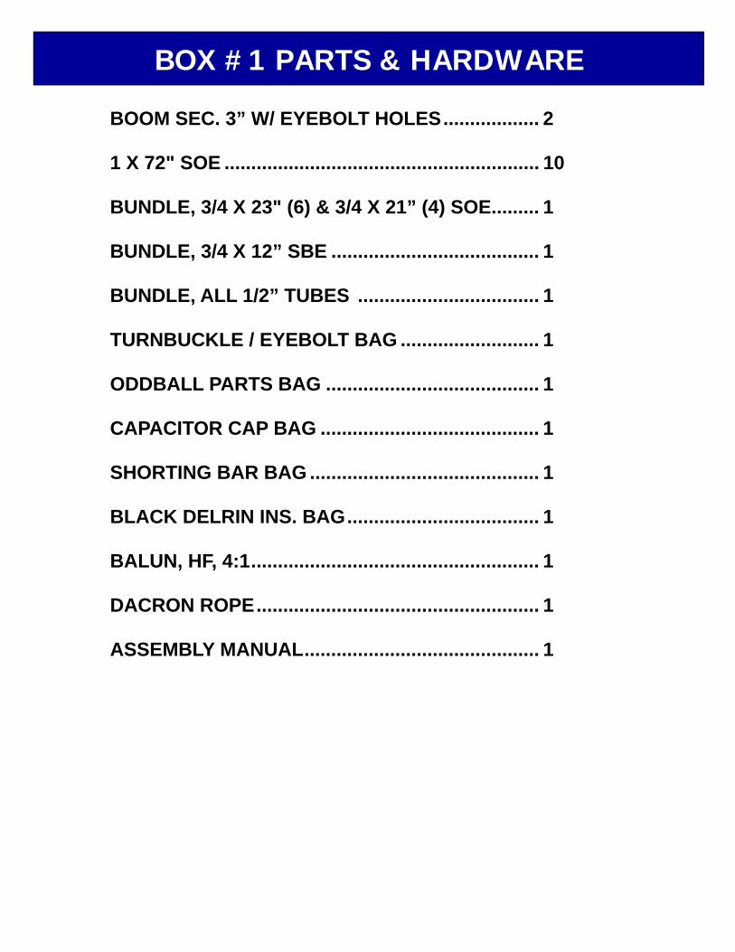
BOOM SEC. 3” W/ EYEBOLT HOLES.................. 2 1 X 72" SOE ........................................................... 10 BUNDLE, 3/4 X 23" (6) & 3/4 X 21” (4) SOE......... 1 BUNDLE, 3/4 X 12” SBE ....................................... 1 BUNDLE, ALL 1/2” TUBES .................................. 1 TURNBUCKLE / EYEBOLT BAG .......................... 1 ODDBALL PARTS BAG ........................................ 1 CAPACITOR CAP BAG ......................................... 1 SHORTING BAR BAG ........................................... 1 BLACK DELRIN INS. BAG.................................... 1 BALUN, HF, 4:1...................................................... 1 DACRON ROPE..................................................... 1 ASSEMBLY MANUAL............................................ 1
BOX #1 PARTS & HARDWARE

BOOM SEC. 3” SOE, NO HOLES ......................... 2 BOOM SEC. 3” X 28” STRAIGHT......................... 1 ODDBALL TUBE BUNDLE.................................... 1 ELEMENT, 3/4 X 48” SOE ..................................... 2 CAPACITOR TUBE BUNDLE................................ 1 SHORT 3/8” TUBE BUNDLE................................. 1 MED. & LONG 3/8” TUBE BUNDLE ..................... 1 FIBERGLASS INSULATOR, 7/8 X 14-3/4”............ 2 BOOM TO MAST PLATE, 1/4 X 6 X 8" ................ 1 SHORT FG ROD BAG ........................................... 1 3” U-BOLT BAG .................................................... 1 2-1/2” & 2” U-BOLT BAG ...................................... 1 CLAMP PLATE BAG.............................................. 1 SADDLE BAG ........................................................ 1 1/4-20 HARDWARE BAG ...................................... 1 8-32 HARDWARE BAG ......................................... 1 CABLE TIES .......................................................... 3
BOX #2 PARTS & HARDWARE