M16C/26 Using UARTs in Asynchronous Modejmconrad/ECGR4101Common/SKP16C2… · M16C/26 Using UARTs...
13
APPLICATION NOTE M16C/26 Using UARTs in Asynchronous Mode 1.0 Abstract The following article introduces and describes how to use the UART’s of the M16C/26 (M30262) Flash microcontroller (MCU) for asynchronous communications. A sample program, using UART0 in asynchronous mode, was written for the MSV30262-SKP connected to a PC using a serial cable. Data sent by the MSV30262 SKP board can be displayed in Hyperterminal application. 2.0 Introduction The Renesas M30262 is a 16-bit MCU based on the M16C/60 series CPU core. The MCU features include up to 64KB of Flash ROM, 2KB of RAM, and 4KB of Virtual EEPROM. The peripheral set includes 10-bit A/D, Timers, DMA, GPIO, and 3 UART’s. Any of the three UART’s (UART0, UART1, and UART2) can be used in asynchronous mode and in synchronous mode. In addition, UART2 also supports I2C and SPI. The block diagrams of the UARTs are shown in , and . Figure 1 Figure 1 UART0 Block Diagram Figure 2 Figure 3 UART (Universal Asynchronous Receive/Transmit) is a common form of serial communications. Without handshaking or flow control, will only require 2 lines, receive and transmit. If handshaking is needed, another 2 lines, CTS (Clear-To-Send) and RTS (Request-To-Send), are required. The remainder of this document shows how to configure a UART, i.e. UART0, in asynchronous mode. REU05B0055-0100Z June 2003 Page 1 of 12
Transcript of M16C/26 Using UARTs in Asynchronous Modejmconrad/ECGR4101Common/SKP16C2… · M16C/26 Using UARTs...
APPLICATION NOTE
M16C/26 Using UARTs in Asynchronous Mode
1.0 Abstract The following article introduces and describes how to use the UART’s of the M16C/26 (M30262) Flash
microcontroller (MCU) for asynchronous communications. A sample program, using UART0 in asynchronous
mode, was written for the MSV30262-SKP connected to a PC using a serial cable. Data sent by the MSV30262
SKP board can be displayed in Hyperterminal application.
2.0 Introduction The Renesas M30262 is a 16-bit MCU based on the M16C/60 series CPU core. The MCU features include up to
64KB of Flash ROM, 2KB of RAM, and 4KB of Virtual EEPROM. The peripheral set includes 10-bit A/D, Timers,
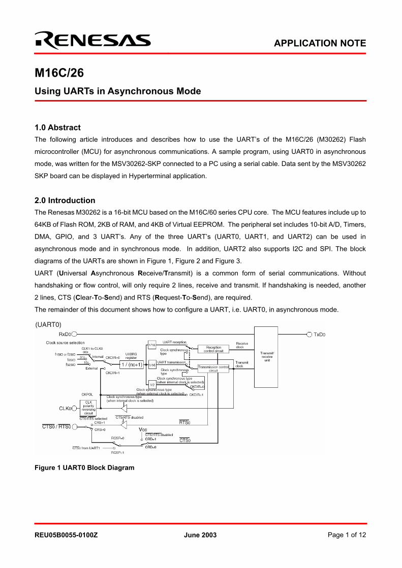
DMA, GPIO, and 3 UART’s. Any of the three UART’s (UART0, UART1, and UART2) can be used in
asynchronous mode and in synchronous mode. In addition, UART2 also supports I2C and SPI. The block
diagrams of the UARTs are shown in , and . Figure 1
Figure 1 UART0 Block Diagram
Figure 2 Figure 3
UART (Universal Asynchronous Receive/Transmit) is a common form of serial communications. Without
handshaking or flow control, will only require 2 lines, receive and transmit. If handshaking is needed, another
2 lines, CTS (Clear-To-Send) and RTS (Request-To-Send), are required.
The remainder of this document shows how to configure a UART, i.e. UART0, in asynchronous mode.
REU05B0055-0100Z June 2003 Page 1 of 12

M16C/26Using UARTs in Asynchronous Mode
Figure 2 UART1 Block Diagram
Figure 3 UART2 Block Diagram
REU05B0055-0100Z June 2003 Page 2 of 12
M16C/26Using UARTs in Asynchronous Mode
3.0 UART
3.1 Parameters
3.1
Parameters
The M16C/26 UART’s are programmable and so given parameters are necessary to be able to configure the
UART’s. These parameters, which are shown below, will vary from one application to another.
• Baud Rate - The baud rate is the speed at which the data is transmitted or received. Examples are 19.2Kbps,
9,600bps, 4,8bps, or 2,400bps. Higher speeds of 115Kbps and 57.6Kbps are available in some applications.
The baud rate is used to calculate the value for the bit rate generator. Use the equation below to calculate the
value for the UARTi Bit Rate Generator, UiBRG.
UiBRG = ((clock source / 16) / baud rate) – 1
Where clock source could be f1, f8, or f32. The clock source is selected from UARTi transmit/receive control
register 0, UiC0.
• Data Length - There are three data lengths to choose from: 7, 8, or 9 bits.
• Stop Bit - There are two options for Stop bits: 1 or 2.
• Parity Bit - There are three options: odd, even, or no parity.
• Transmission/Reception (Handshaking or Flow) Control - The available options are: CTS, RTS, or no
control. Having some form of transmission/reception control will minimize data errors because data is only sent
when one party is ready to receive.
3.2 Configuring the UART The steps necessary to configure a UART are shown below. An example using these steps can be found in the
init_uart() routine of the sample program.
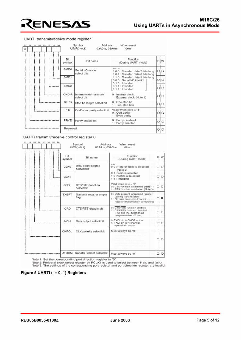
1. Initialize the UARTi transmit/receive mode register, UiMR, based on parameters discussed in section
.
2. Initialize UARTi transmit/receive control register 0, UiC0, based on baud rate and flow control.
3. Initialize UARTi bit rate generator, UiBRG, using the calculated value based on baud rate and clock source
selected in UiC0.
4. Initialize UART transmit/receive control register 2, UCON, based on flow control.
5. Initialize UARTi interrupt vector SiTIC for transmit and SiRIC for receive.
6. Enable transmit and receive using UARTi transmit control register 1, UiC1.
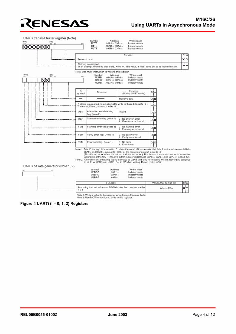
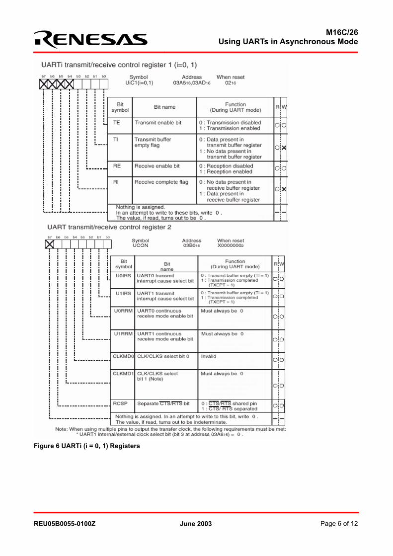
There are several registers used to configure the UART. To simplify the article, we are only going to show the
registers used for configuring UART0 (or UART1), which are shown in Figure 4 to Figure 6.
After initialization, you can start sending and receiving data.
REU05B0055-0100Z June 2003 Page 3 of 12
M16C/26Using UARTs in Asynchronous Mode
Figure 4 UARTi (i = 0, 1, 2) Registers
REU05B0055-0100Z June 2003 Page 4 of 12
M16C/26Using UARTs in Asynchronous Mode
Figure 5 UARTi (i = 0, 1) Registers
REU05B0055-0100Z June 2003 Page 5 of 12
M16C/26Using UARTs in Asynchronous Mode
Figure 6 UARTi (i = 0, 1) Registers
REU05B0055-0100Z June 2003 Page 6 of 12
M16C/26Using UARTs in Asynchronous Mode
4.0 UART Demo Program The demo program was written to run on the MSV30262-SKP board with a null modem connected to the PC’s
RS-232C serial port. The Hyperterminal program (or any terminal program that can connect to the COM port) in
Windows™ is used to view the data sent by the M16C/26. Like our parameters to configure UART0, the
Hyperterminal must be configured to 19.2Kbps, one stop bit, no parity, and no flow control.
As soon as a connection is established, incrementing data, 0 to 9, is displayed on Hyperterminal window.
Pressing the ‘z’ key on the keyboard will stop the M16C/26 from sending data. Pressing any other key will
resume data transmission. An interrupt is generated every time a character is received.
The program was compiled using the KNC30 Compiler, which also came with the MSV30262-SKP. It can be
modified to suit a user application.
5.0 Conclusion Asynchronous mode offers simple communications using only two pins (when no handshaking is required). Due
to this simple connectivity, it is easy to implement. Understanding the key parameters simplifies setup and
usage.
6.0 Reference
Renesas Technology Corporation Semiconductor Home Page
http://www.renesas.com
E-mail Support
Data Sheets
• M16C/26 datasheets, M30262eds.pdf
User’s Manual
• M16C/20/60 C Language Programming Manual, 6020c.pdf
• M16C/20/60 Software Manual, 6020software.pdf
• Interrupt Handler App Note, M16C26_Interrupt_Handlers_in_C.doc
• MSV30262-SKP Users Manual, Users_Manual_MSV30262.pdf
REU05B0055-0100Z June 2003 Page 7 of 12
M16C/26Using UARTs in Asynchronous Mode
7.0 Software Code /***************************************************************************** * File Name: main_uart.c * * Content: This program communicates from the M16C/26 to a terminal * program via UART0 and RS232. UART0 configuration is: * 19200 baud rate, 8-bit data, 1 stop bit, no parity, no flow control. * * This program was written to run on the MSV30262 Board. * To see the data sent, use Hyperterminal configured as mentioned * above and connect a null modem cable between P1 and the PC's * com port. * * An incrementing data (0 to 9) is sent to the Hyperterminal window. * To stop receiving data, press z on the keyboard. To resume, press * any key. * * Version: 1.0 * Date: 05-09-03 * * Copyright 2003 Renesas Technology America, Inc. * All rights reserved *============================================================================= * $Log:$ *===========================================================================*/ /* Include files */ #include "..\common\sfr262.h" // include M16C/26 header file /* Setup interrupt routine for UART0 receive. This must also be setup in the vector table in SECT30_UART.INC */ #pragma INTERRUPT U0rec_ISR void U0rec_ISR (void); /* Function Prototypes */ void text_write (_far char * msg_string); void mcu_init(void); void uart_init(void); /* Global variables */ char U0_in; // declare UART0 recieve variable /* String constants used for screen output **********************************/ const char cmd_clr_scr[] = {27,'[','2','J',0}; const char cmd_cur_home[] = {27,'[','H',0}; /***************************************************************************** Name: Main Parameters: none Returns: none Description: This is the main program *****************************************************************************/
REU05B0055-0100Z June 2003 Page 8 of 12

M16C/26Using UARTs in Asynchronous Mode
main() { int count; // declare count variable int convert; // declare ASCII variable unsigned int delay; // declare delay variable int i; // declare string pointer variable mcu_init(); // MCU initialization uart_init(); // UART initialization /* Text to be displayed at the beginning of the program output to the terminal window (\r\n = carriage return & linefeed) */ text_write(cmd_clr_scr); // clear screen text_write(cmd_cur_home); // home cursor text_write("Renesas Technology America, Inc. \r\n"); text_write("Renesas MSV30262-SKP UART demo. \r\n"); text_write("Press z to stop, any key to continue. \r\n"); /************** MAIN PROGRAM LOOP ***********************/ while (1){ // setup program loop to count from 0 to 9, stop when "z" is received while (U0_in != 'z'){ // count as long as "z" wasn't pressed text_write("\r\n"); // send carrige return and line feed for (count=0;(count<=9)&&(U0_in!='z');count ++){ // count 0 to 9 convert = count + 0x30; // convert count data to ASCII while(ti_u0c1 == 0); // wait for previous transmission to complete u0tb = convert; // put ASCII data in transmit buffer p7_0 = 1; // turn off red LED p7_2 = ~p7_2; // blink run LED D5 for (delay=0x3fff; delay>0; delay--); // Count Delay } } asm("NOP"); // Do nothing while stopped } // (after "z" is pressed) } /***************************************************************************** Name: UART0 Receive Interrupt Routine Parameters: none Returns: none Description: Interrupt routine for UART0 receive Reads character received from keyboard and stores U0_in variable *****************************************************************************/ void U0rec_ISR(void){ while(ri_u0c1 == 0); // make sure receive is complete U0_in = u0rb; // read in received data if (U0_in == 'z'){ // If "z" was entered do the following: while(ti_u0c1 == 0); // wait for previous transmission to complete u0tb = 'z'; // echo "z" to screen p7_2 = 1; // turn off green LED p7_0 = 0; // turn on red LED } }
REU05B0055-0100Z June 2003 Page 9 of 12
M16C/26Using UARTs in Asynchronous Mode
/***************************************************************************** Name: text_write Parameters: msg_string -> the text string to output Returns: none Description: The following sends a text string to the terminal program *****************************************************************************/ void text_write ( _far char * msg_string) { char i; for (i=0; msg_string[i]; i++){ // This loop reads in the text string and while(ti_u0c1 == 0); // puts it in the UART 0 transmit buffer u0tb = msg_string[i]; } } /***************************************************************************** Name: mcu_init Parameters: None Returns: None Description: Initialization routine for the different MCU peripherals. See settings for details. *****************************************************************************/ void mcu_init(void) { /* LED initialization */ pd7_0 = 1; // Change LED ports to outputs (connected to LEDs) pd7_1 = 1; pd7_2 = 1; p7 |= 0x7; // turn off LEDs /* unused pins - configure as outputs to decrease power consumption */ pd6 |= 0x9F; pd7 |= 0xF8; pd8_0 |= 0x2F; prc2 = 1; // P9 is write protected - disable protection before writing to P9 pd9 |= 0x0F; prc2 = 0; // Write protect P9 pd10 |= 0x1F; // upper bits are switch inputs } /***************************************************************************** Name: uart_init Parameters: None Returns: None Description: Uart0 initialization - 19200 baud, 8 data bits, 1 stop bit, no parity. *****************************************************************************/
REU05B0055-0100Z June 2003 Page 10 of 12
M16C/26Using UARTs in Asynchronous Mode
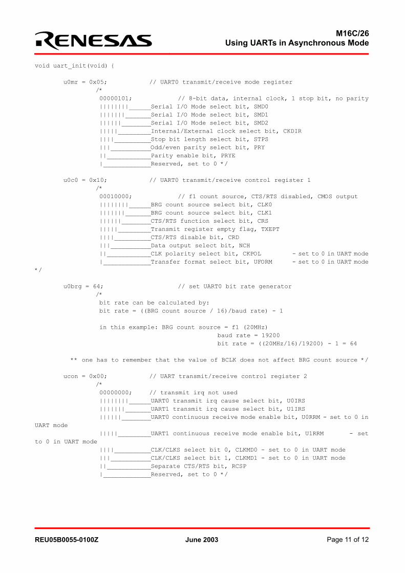
void uart_init(void) { u0mr = 0x05; // UART0 transmit/receive mode register /* 00000101; // 8-bit data, internal clock, 1 stop bit, no parity ||||||||______Serial I/O Mode select bit, SMD0 |||||||_______Serial I/O Mode select bit, SMD1 ||||||________Serial I/O Mode select bit, SMD2 |||||_________Internal/External clock select bit, CKDIR ||||__________Stop bit length select bit, STPS |||___________Odd/even parity select bit, PRY ||____________Parity enable bit, PRYE |_____________Reserved, set to 0 */ u0c0 = 0x10; // UART0 transmit/receive control register 1 /* 00010000; // f1 count source, CTS/RTS disabled, CMOS output ||||||||______BRG count source select bit, CLK0 |||||||_______BRG count source select bit, CLK1 ||||||________CTS/RTS function select bit, CRS |||||_________Transmit register empty flag, TXEPT ||||__________CTS/RTS disable bit, CRD |||___________Data output select bit, NCH ||____________CLK polarity select bit, CKPOL - set to 0 in UART mode |_____________Transfer format select bit, UFORM - set to 0 in UART mode */ u0brg = 64; // set UART0 bit rate generator /* bit rate can be calculated by: bit rate = ((BRG count source / 16)/baud rate) - 1 in this example: BRG count source = f1 (20MHz) baud rate = 19200 bit rate = ((20MHz/16)/19200) - 1 = 64 ** one has to remember that the value of BCLK does not affect BRG count source */ ucon = 0x00; // UART transmit/receive control register 2 /* 00000000; // transmit irq not used ||||||||______UART0 transmit irq cause select bit, U0IRS |||||||_______UART1 transmit irq cause select bit, U1IRS ||||||________UART0 continuous receive mode enable bit, U0RRM - set to 0 in UART mode |||||_________UART1 continuous receive mode enable bit, U1RRM - set to 0 in UART mode ||||__________CLK/CLKS select bit 0, CLKMD0 - set to 0 in UART mode |||___________CLK/CLKS select bit 1, CLKMD1 - set to 0 in UART mode ||____________Separate CTS/RTS bit, RCSP |_____________Reserved, set to 0 */
REU05B0055-0100Z June 2003 Page 11 of 12
M16C/26Using UARTs in Asynchronous Mode
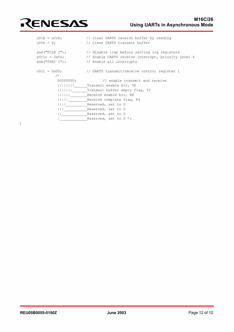
u0tb = u0rb; // clear UART0 receive buffer by reading u0tb = 0; // clear UART0 transmit buffer asm("FCLR I"); // disable irqs before setting irq registers s0ric = 0x04; // Enable UART0 receive interrupt, priority level 4 asm("FSET I"); // Enable all interrupts u0c1 = 0x05; // UART0 transmit/receive control register 1 /* 00000000; // enable transmit and receive ||||||||______Transmit enable bit, TE |||||||_______Transmit buffer empty flag, TI ||||||________Receive enable bit, RE |||||_________Receive complete flag, RI ||||__________Reserved, set to 0 |||___________Reserved, set to 0 ||____________Reserved, set to 0 |_____________Reserved, set to 0 */ }
REU05B0055-0100Z June 2003 Page 12 of 12
Keep safety first in your circuit designs!
• Renesas Technology Corporation puts the maximum effort into making semiconductor products
better and more reliable, but there is always the possibility that trouble may occur with them. Trouble with semiconductors may lead to personal injury, fire or property damage. Remember to give due consideration to safety when making your circuit designs, with appropriate measures such as (i) placement of substitutive, auxiliary circuits, (ii) use of nonflammable material or (iii) prevention against any malfunction or mishap.
Notes regarding these materials
• These materials are intended as a reference to assist our customers in the selection of the Renesas Technology Corporation product best suited to the customer's application; they do not convey any license under any intellectual property rights, or any other rights, belonging to Renesas Technology Corporation or a third party.
• Renesas Technology Corporation assumes no responsibility for any damage, or infringement of any third-party's rights, originating in the use of any product data, diagrams, charts, programs, algorithms, or circuit application examples contained in these materials.
• All information contained in these materials, including product data, diagrams, charts, programs and algorithms represents information on products at the time of publication of these materials, and are subject to change by Renesas Technology Corporation without notice due to product improvements or other reasons. It is therefore recommended that customers contact Renesas Technology Corporation or an authorized Renesas Technology Corporation product distributor for the latest product information before purchasing a product listed herein. The information described here may contain technical inaccuracies or typographical errors. Renesas Technology Corporation assumes no responsibility for any damage, liability, or other loss rising from these inaccuracies or errors. Please also pay attention to information published by Renesas Technology Corporation by various means, including the Renesas Technology Corporation Semiconductor home page (http://www.renesas.com).
• When using any or all of the information contained in these materials, including product data, diagrams, charts, programs, and algorithms, please be sure to evaluate all information as a total system before making a final decision on the applicability of the information and products. Renesas Technology Corporation assumes no responsibility for any damage, liability or other loss resulting from the information contained herein.
• Renesas Technology Corporation semiconductors are not designed or manufactured for use in a device or system that is used under circumstances in which human life is potentially at stake. Please contact Renesas Technology Corporation or an authorized Renesas Technology Corporation product distributor when considering the use of a product contained herein for any specific purposes, such as apparatus or systems for transportation, vehicular, medical, aerospace, nuclear, or undersea repeater use.
• The prior written approval of Renesas Technology Corporation is necessary to reprint or reproduce in whole or in part these materials.
• If these products or technologies are subject to the Japanese export control restrictions, they must be exported under a license from the Japanese government and cannot be imported into a country other than the approved destination. Any diversion or reexport contrary to the export control laws and regulations of Japan and/or the country of destination is prohibited.
• Please contact Renesas Technology Corporation for further details on these materials or the products contained therein.