
M04 BIRC4058 05 SE C04.QXD 3/29/07 12:04 PM Page 61 Chapter Books/Manual... · 62 CHAPTER 4 46106 C...
25
After studying Chapter 4, the reader should be able to: 1. Identify the parts of a clutch assembly and know the purpose of each. 2. Explain the requirements for good, smooth clutch operation. Auburn assembly (p. 67) Automatic clutch actuation (p. 81) Borg and Beck assembly (p. 67) Clutch cable (p. 77) Clutch disc (p. 62) Clutch fork (p. 63) Clutch housing (p. 73) Clutch plate (p. 62) Coefficient of friction (p. 63) Cone clutch (p. 80) Cover (p. 67) Cushioned disc (p. 64) Damper (p. 64) Diaphragm assembly (p. 67) Chapter 4 CLUTCH THEORY CLUTCH THEORY 3. Identify the components used to operate a clutch. Dog clutch (p. 80) Dual mass flywheel (p. 81) Engagement modulation (p. 63) Facing (p. 63) Fluid clutch (p. 80) Flywheel (p. 62) Hub and damper assembly (p. 63) Hydraulic clutch (p. 78) Hydraulic system (p. 78) Internal expanding shoe clutch (p. 80) Lining (p. 63) Linkage (p. 63) Long assembly (p. 69) Magnetic clutch (p. 80) Marcel (p. 67) Modular clutch (p. 72) One-way clutch (p. 80) Pilot bearing (p. 73) Pivot shaft (p. 73) Pressure plate assembly (p. 62) Pressure ring (p. 67) Pressure springs (p. 67) Release bearing (p. 63) Release bearing support (p. 63) Release levers (p. 67) Sprag clutch (p. 80) Stepped flywheel (p. 72) Throw-out bearing (p. 63) Wet clutch (p. 80) OBJECTIVES KEY TERMS
-
Upload
vuongthien -
Category
Documents
-
view
213 -
download
0
Transcript of M04 BIRC4058 05 SE C04.QXD 3/29/07 12:04 PM Page 61 Chapter Books/Manual... · 62 CHAPTER 4 46106 C...

46106 C PH OH A Bi h P N 61 K/PMS DESIGN SERVICES OF
After studying Chapter 4, the reader should be able to:
1. Identify the parts of a clutch assembly and know the purpose of each.
2. Explain the requirements for good, smooth clutch operation.
Auburn assembly (p. 67)
Automatic clutch actuation (p. 81)
Borg and Beck assembly (p. 67)
Clutch cable (p. 77)
Clutch disc (p. 62)
Clutch fork (p. 63)
Clutch housing (p. 73)
Clutch plate (p. 62)
Coefficient of friction (p. 63)
Cone clutch (p. 80)
Cover (p. 67)
Cushioned disc (p. 64)
Damper (p. 64)
Diaphragm assembly (p. 67)
Chapter 4
CLUTCH THEORYCLUTCH THEORY
3. Identify the components used to operate a clutch.
Dog clutch (p. 80)
Dual mass flywheel (p. 81)
Engagement modulation (p. 63)
Facing (p. 63)
Fluid clutch (p. 80)
Flywheel (p. 62)
Hub and damper assembly (p. 63)
Hydraulic clutch (p. 78)
Hydraulic system (p. 78)
Internal expanding shoe clutch (p. 80)
Lining (p. 63)
Linkage (p. 63)
Long assembly (p. 69)
Magnetic clutch (p. 80)
Marcel (p. 67)
Modular clutch (p. 72)
One-way clutch (p. 80)
Pilot bearing (p. 73)
Pivot shaft (p. 73)
Pressure plate assembly (p. 62)
Pressure ring (p. 67)
Pressure springs (p. 67)
Release bearing (p. 63)
Release bearing support (p. 63)
Release levers (p. 67)
Sprag clutch (p. 80)
Stepped flywheel (p. 72)
Throw-out bearing (p. 63)
Wet clutch (p. 80)
OBJECTIVES
KEY TERMS
M04_BIRC4058_05_SE_C04.QXD 3/29/07 12:04 PM Page 61

62 CHAPTER 4
46106 C PH OH A Bi h P N 62 K/PMS DESIGN SERVICES OF
APPLIED
RELEASED
FIGURE 4-2 A clutch is applied when the spring(s) pushes the pres-sure plate toward the flywheel, squeezing the disc against the flywheel (top).Pushing on the clutch pedal forces the release bearing to pull the pressure plateaway from the disc, releasing the clutch (bottom). (Courtesy of LUK Clutches)
1 2 3 5
4
189
6
8
7
19
16
20
21
10
1112
1314
15
17
1. CLUTCH HOUSING BOLTS 2. FLYWHEEL 3. CLUTCH COVER BOLTS 4. RELEASE FORK 5. RELEASE FORK PIVOT 6. TRANSMISSION INPUT SHAFT BEARING 7. SLAVE CYLINDER 8. INPUT SHAFT SEAL 9. RELEASE BEARING SUPPORT10. RELEASE BEARING11. DIAPHRAGM SPRING
12. CLUTCH COVER13. CLUTCH HOUSING14. HOUSING ALIGNMENT DOWEL15. ENGINE BLOCK SURFACE16. REAR MAIN SEAL17. CRANKSHAFT FLANGE18. PILOT BEARING19. TRANSMISSION INPUT SHAFT20. FLYWHEEL BOLT21. CLUTCH DISC
FIGURE 4-1 Cutaway (a) and exploded (b) view of a clutch assembly,showing the various components. (Courtesy of DaimlerChrysler Corporation)
321
INTRODUCTION
The clutch connects the engine to the transmission. It is dis-engaged to allow the driver to select the appropriate gearrange. You may remember the first time you drove a vehiclewith a manual transmission. The first few times you let theclutch out the engine stalled or the vehicle jumped forward.You soon learned to feather the clutch. Engaging the clutchslowly and increasing the engine speed allowed the vehicle tomove smoothly from a stop.
The major parts of a clutch assembly are the pressureplate assembly, flywheel, and clutch disc (Figure 4-1). Thepressure plate and flywheel are the clutch input members andrevolve at engine speed. The clutch disc is the output mem-ber. It is splined to the transmission input shaft and providesinput to the transmission.
The clutch disc also called a clutch plate is firmlyclamped between the flywheel and pressure plate when theclutch is engaged. This will allow the engine’s torque to betransferred to the transmission (Figure 4-2). When the clutchis disengaged, the pressure plate will move away from the disc
M04_BIRC4058_05_SE_C04.QXD 3/29/07 12:04 PM Page 62

Clutch Theory 63
46106 C PH OH A Bi h P N 63 K/PMS DESIGN SERVICES OF
Clutch Disc Cushion DeflectionPlus Runout
PEDAL TRAVEL
Clutch Engaged
Clutch Disengaged
Engagement Modulation
Maximum Engine Torque
Clutch Safety Factor
Maximum Clutch Torque
BottomTop
Free Travel
Going Up, Engage
Going Down, Disengage
Clutch PedalReserve
Disc Movementon Clutch Shaft
First Point ofEngagement
FIGURE 4-3 Clutch pedal travel (center) causes several things to occur during disengagement (top, at left) and engagement (bottom, at right).
shown in Figure 4-4, which compares the force that it takes toslide rubber (the tire) over dry pavement, wet pavement, andice. Tire traction suffers from friction loss when a road be-comes wet and almost disappears when ice forms. Similarly, ifthe coefficient of friction of the clutch were less, it might slipand not transmit the required torque. If the friction coefficientwere greater, the clutch would become more aggressive andgrabby, and engagement would be harsh and severe.
In addition to the pressure plate assembly and disc, theclutch needs a method to release it; this is accomplished by therelease bearing, clutch fork, and linkage. The release bear-ing, also called a throw-out bearing, is mounted on therelease bearing support, also called a bearing guide, candle-stick, or quill, that is built into the transmission front bearing re-tainer. When the clutch pedal is depressed, the linkage andclutch fork force the release bearing against the release levers ordiaphragm fingers of the pressure plate assembly. This causesthe pressure plate to move rearward, releasing the clutch.
CLUTCH DISCS
A variety of discs are available, with each disc incorporatingdesign features that make it most suitable for a particular ap-plication. A disc is made up of several major parts: the huband damper assembly, facing or lining, and plate or webwith marcel (Figure 4-5). Disc size is measured at the outsidediameter of the friction material.
Clutch Hub and Damper Assembly
The clutch hub has internal splines (from 10 to 26) that slideover the external splines of the transmission input/clutch shaft.
and flywheel, which releases the pressure on the disc. Thepower flow through the clutch will be interrupted.
The clutch must transmit the engine torque without slip-ping when completely engaged but allow controlled slippageas the clutch is being engaged. Clutch engagement begins asthe clutch disc is squeezed between the flywheel and pressureplate. The torque transfer through the clutch increases untilthe clutch is completely engaged. The controlled slip is knownas clutch engagement modulation (Figure 4-3).
The amount of torque that a clutch can transmit is a prod-uct of the contact surface area that exists between the clutchdisc, pressure plate and flywheel, the coefficient of friction ofthe disc lining, and how tightly the disc is squeezed. The for-mula used to the compute the clutch capacity is:
T = n × f × F × r
where:
T = torque in foot-poundsn = number of friction surfaces (two per disc)f = facing coefficient of friction (0.25 is average)F = total effective pressure (clamping force) in poundsr = mean effective radius of lining in feet [(inside radius +
outside radius) ÷ 2]
Torque capacity will increase if friction surfaces are added(two or three disc clutches are sometimes used), the coeffi-cient of friction is increased (clutch grab might occur), thespring pressure is increased (clutch pedal effort will increase),or a larger mean radius (larger disc, pressure plate, and fly-wheel) is used.
Coefficient of friction describes the relative amount offriction between two surfaces. A simple explanation of this is
M04_BIRC4058_05_SE_C04.QXD 3/29/07 12:04 PM Page 63

64 CHAPTER 4
FIGURE 4-5 Exploded view of a clutch disc, showing the variousparts. (Courtesy of McLeod Industries, Inc.)
APPLIED
RELEASED
FIGURE 4-6 During apply and release, the clutch hub must slideslightly on the transmission shaft, as the facing moves toward or away from theflywheel.
FIGURE 4-4 (a) The coefficient of friction between a tire and drypavement is about 0.9, providing enough traction to steer and stop safely.(b) Rain will lower the friction coefficient to about 0.5, limiting traction. (c) Icewill reduce the coefficient of friction to about 0.1,making stopping and steeringdifficult and somewhat dangerous.
Each time the clutch is applied, the disc must slide forwardslightly to contact the flywheel, and it must slide back to preventdrag on the flywheel when the clutch is released (Figure 4-6).
Most discs include a damper assembly as part of the hub,and these are called cushioned (or dampened) discs. A fewdiscs have the hub secured solidly to the web and are calledrigid discs (Figure 4-7). An engine produces uneven power im-pulses that cause tortional vibration. The damper reduces thetorsional vibrations that result from the uneven engine powerimpulses from the rest of the drivetrain. As an engine goesthrough its power cycle, the crankshaft will try to speed up and
46106 C PH OH A Bi h P N 64 K/PMS DESIGN SERVICES OF
M04_BIRC4058_05_SE_C04.QXD 3/29/07 12:04 PM Page 64

Clutch Theory 65
(a) (b)
FIGURE 4-7 Cushioned disc (a) and rigid disc (b) that has the plateconnected directly to the hub. (Courtesy of McLeod Industries, Inc.)
SpeedFluctuations Reduced
Fluctuations
Dampening
(a)
(b)
50
-50
Engine Transmission
Time
Spe
ed F
luct
uatio
n(r
pm)
0
FIGURE 4-8 (a) When an engine runs, the crankshaft and flywheelmust speed up and slow during each revolution. (b) The torsional springs anddamper assembly reduce these speed fluctuations. (Courtesy of LUK Clutches)
46106 C PH OH A Bi h P N 65 K/PMS DESIGN SERVICES OF
slow down during portions of each revolution. If these slightspeed fluctuations are not removed by the damper, they will cause“gear rattle,” vibration, noise, and increased wear (Figure 4-8).The damper assembly is composed of the hub with four to eightopenings or fingerlike extensions, one or more springs for eachextension, a spring washer, and a friction washer. These parts arefitted between the web of the disc and a metal retainer and areheld together by a series of rivets called stop pins, which alsokeep the hub from revolving too far. The damper springs are po-sitioned by a series of windows in the web and retainer. Thetorque must pass through the damper springs on its way fromthe engine to the transmission, and any power impulses that
tend to speed up the clutch hub will compress the springs. Thesprings will reextend when there is a torque lag. The springsand washer portion of a damper assembly are designed to ab-sorb the engine’s torsional vibrations.
Clutch Facing
The clutch friction material must be able to withstand the heatgenerated by that friction during engagement and disengage-ment. Traditionally, a mixture of either molded or woven as-bestos has been used with various filler and binder materials.Asbestos is nearly an ideal friction material for brake lining andclutch facing because it has a very good coefficient of friction,excellent heat characteristics, and low cost. However, the pos-sibility of getting cancer from inhaling asbestos fibers hasgreatly reduced its use. Federal law banned the manufactureof asbestos-containing clutch facings after August 1992. As-bestos is being replaced with fiberglass and aramid nonmetal-lic compounds and metallic materials. Various mixtures ofpowdered iron, copper, graphite, and ceramics are used to ob-tain the desired friction and wear characteristics. At one time,asbestos-based facings were classed as organic materials.
The wear rate and coefficient of friction of nonmetallic fac-ings is greatly affected by temperature, as shown in Figure 4-9. Ifthe facing is overheated, its capacity to transmit torque is lowered,
FIGURE 4-9 As the clutch facing temperature increases, its ability totransfer torque decreases (top) and its wear rate increases (bottom). Facing A is a normal production facing material; facing B is a heavy-duty, high-performance facing. (Courtesy of Ford Motor Company)
M04_BIRC4058_05_SE_C04.QXD 3/29/07 12:04 PM Page 65

66 CHAPTER 4
Engine Side Transmission Side
10
2
12
3
11
9
4
12
5
13
14
810
5
13
9
Rivets
11
6
7
9
43
Facing
2
1
Engine Side Transmission Side
8.9.
10.11.12.13.14.
Support WasherTorsion Damper Spring, 1st StageTorsion Damper Spring, 2nd StageHubRetainer PlateCover PlateHub Flange
3
Clutch FacingFacing RivetSegmentSegment RivetStop PinDiaphragm Spring, Spring WasherFriction Washer
1.2.3.4.5.6.7.
FIGURE 4-10 The facing is riveted to one end of the marcel segments in an alternating manner.This allows the marcel to expand while the clutch is releasedand compress during clutch engagement. (Courtesy of LUK Clutches)
and this will probably cause slippage and more heat. As the tem-perature increases, the binders holding the facing material to-gether will lose their strength, greatly increasing the wear rate. Itis possible for the facing to last many thousands of miles and thenbecome worn out in one prolonged period of slipping and heating.
The facing is attached to the marcel by a series of rivetsinstalled in counterbored holes or by bonding (Figure 4-10).Some metallic facings are formed directly onto a steel backing.If there is less than 0.015 in. (0.38 mm) of facing above therivets or backing, a disc is considered worn out.
Most nonmetallic facings have a series of radial groovescut across their surface (Figure 4-11). These grooves wipe dustand dirt from the surfaces of the flywheel and pressure plate.They also promote an airflow to help cool the friction surfacesand prevent a vacuum that might cause the friction surfaces to
46106 C PH OH A Bi h P N 66 K/PMS DESIGN SERVICES OF
SafetyTipAs asbestos facing wears, minute parti-cles of lightweight asbestos fibers
break off. If one or more of these fibers lodge in the lin-ing of your nose, throat, nasal passage, or lungs, theycan produce cancer. When working around automotiveclutch or brake assemblies, you should be extra carefulnot to let the dust particles enter the air or inhale any ofthese airborne particles.
M04_BIRC4058_05_SE_C04.QXD 3/29/07 12:04 PM Page 66

Clutch Theory 67
46106 C PH OH A Bi h P N 6 K/PMS DESIGN SERVICES OF
stick together during release. Sticking during release willcause clutch drag. Some metallic discs have a series of radialslots cut across the facing; these slots allow the disc to expandwithout warping when it gets hot.
Retainer Plate
The retainer plate of the disc connects the facing (where thetorque enters) to the hub (where it leaves). It also contains themarcel, which is a series of wave springs. Figure 5-12 showshow the facing is attached to the marcel so that the disc cancompress as the clutch is applied. This causes a slight time lagthat allows the clutch to apply more smoothly. Clutch discsused for racing, where smooth operation is not necessary, of-ten do not have marcels.
PRESSURE PLATE
ASSEMBLIES
The pressure plate assembly is a combination of the pressurering (plate), cover (also called a hat ), pressure springs, andrelease levers (also called fingers). There are four basic stylesof pressure plates: Auburn, Borg and Beck, diaphragm, andLong (Figure 5-13). Three of these styles are named for theirearly manufacturer, and one is named for the type of springused. The major characteristics of each design are as follows:
● Auburn: very open cover; springs act through the lever-age of the release levers; uses three or six springs; mount-ing holes are three groups of one or two holes.
● Borg and Beck: the most closed cover; three widestamped-steel release levers; up to 12 springs; usually hassix evenly spaced mounting holes.
● Diaphragm: a ringlike cover; uses a many-fingered di-aphragm spring, which also serves as the release lever;usually has six evenly spaced mounting holes.
FIGURE 4-11 Most asbestos and nonasbestos organic facings have aseries of grooves cut across the surface. (Courtesy of LUK Clutches)
FIGURE 4-12 When a clutch is released, the marcel springs expandthe thickness of the facing (bottom). During reapplication of the clutch, thesesegments compress, causing a slight lag and much smoother application(top). (Courtesy of LUK Clutches)
M04_BIRC4058_05_SE_C04.QXD 3/29/07 12:04 PM Page 67

68 CHAPTER 4
46106 C PH OH A Bi h P N 68 K/PMS DESIGN SERVICES OF
Borg & Beck Style Diaphragm Style Long Style
(a) (b) (c)
Bracket
ReleaseLevers
Springs
Plate
(g)
FIGURE 4-13 The major styles of pressure plate assembly are Borgand Beck (a and d), diaphragm (b and e), and Long (c and f); the Auburn design(g) is used occasionally. d, e, and f are exploded views. (a, b, and c are courtesyof RAM Automotive; d, e, and f are courtesy of McLeod Industries, Inc.; g is repro-duced with permission of Deere & Company, © 1972 Deere & Company. All rightsreserved.)
M04_BIRC4058_05_SE_C04.QXD 3/29/07 12:04 PM Page 68

Clutch Theory 69
46106 C PH OH A Bi h P N 69 K/PMS DESIGN SERVICES OF
● Long: a somewhat triangular cover; three narrow, forged-steel release levers, which extend through the cover and of-ten have weights on them; usually uses nine springs;usually has mounting bolt holes in three groups of two.
The Borg and Beck diaphragm designs are the most com-mon at this time. The Auburn design is not commonly used on modern passenger vehicles. The relatively low height of the diaphragm design is highly favored for modern trans-verse engine vehicles where engine and transaxle length arecritical.
The pressure plate used on a few FWD vehicles is bolteddirectly onto the engine’s crankshaft, and the flywheel isbolted onto the pressure plate. This allows the release bearingto be placed inside the pressure plate and operated by a pullrod through the transmission input shaft. It is often called apull-type clutch (Figure 4-14a).
Another pull-type clutch style is a modification of a di-aphragm clutch. The mounting of the diaphragm spring ismoved in the cover and at the pressure ring so a pulling forceis used to release the clutch instead of the normal pushing force(Figure 4-14b and c). This change produces an improvementin clutch system efficiency and a lower clutch pedal effort.
Pressure Ring
A pressure ring is simply a flat, fairly heavy ring usually madefrom cast iron. The heavy weight is necessary to dissipate heatand have sufficient heat sink so as not to warp. It also providessufficient strength so it will spread the spring force evenly ontothe disc. For high-rpm use, the ring is made from cast steel be-cause centrifugal force can cause a cast iron ring to explode.
When a clutch slips, heat is generated at the frictionsurfaces, and this heat will warm up both the facing and the
(a)(b)
Cover Fulcrum
Pressure-PlateFulcrum
BA
Lever Ratio= B/A
Push-Type Clutch
Release Bearing
(c)
Pull-Type Clutch
Cover Fulcrum
Pressure-PlateFulcrum
Release Bearing
BA
Lever Ratio= B/A
FIGURE 4-14 (a) One older design, pull-type pressure plate assembly is operated through a push rod that slides through the transaxle shaft; note how theclutch cover attaches to the crankshaft.(b) A more common pull style connects the release bearing to the diaphragm fingers so that the release bearing can pull on them.A pull clutch has a better lever ratio, as shown in c. (a is courtesy of LUK Clutches; b is courtesy of Toyota Motor Sales USA, Inc.)
M04_BIRC4058_05_SE_C04.QXD 3/29/07 12:04 PM Page 69

70 CHAPTER 4
46106 C PH OH A Bi h P N 0 K/PMS DESIGN SERVICES OF
FIGURE 4-15 The pressure plate clamping load of a diaphragmspring clutch actually increases slightly as the facing wears (top).The releasebearing load increases only slightly after the point of pressure plate lift-off (bot-tom). (Courtesy of LUK Clutches)
pressure ring. Excess heat will cause the pressure ring to ex-pand to the point of warpage, destroying its flatness andcausing poor ring-to-facing contact. The greater the mass ofthe pressure ring, the less the temperature will rise becausethe heat will spread through more metal.
Torque enters the pressure ring from the cover, eitherthrough a drive strap or a boss where the release levers extendthrough openings in the cover. Torque passes out through thefriction contact with the facing on the disc.
Pressure plate diameter is measured at the outside diam-eter of the pressure plate ring. It should always be the samesize or slightly larger than the disc diameter.
Cover
The cover is the stamped-steel housing that transmits thetorque from the flywheel to the pressure ring. It also providesa mounting place for the springs and release levers and, itmust be strong enough to contain the various forces withoutdistorting.
Pressure Springs
A diaphragm spring or a group of coil springs provides theclamping force needed to transmit the torque through theclutch assembly. Coil springs are wound from a metal wirethat has good high-temperature characteristics. The strengthor rate of the spring is determined by the diameter of the wire,the diameter of the coil, the overall length, and the number ofcoils. Referring to the formula on page 63, it would take 800 lb(364 kg) of force on a single-plate, 10-in. clutch to transmit the300 ft-lb (407 N-m) of torque that a 305-in3 (5-L) V8 enginecan produce. The springs used in the pressure plate are of thesize and number to produce the clamping force needed tokeep the clutch from slipping.
A diaphragm spring is a type of Belleville spring that canalso produce the needed clamping force. The conical shape ofthe diaphragm spring resists flattening, and this resistance pro-duces the spring’s force. It also produces an interestingstrength-to-compression curve in that it produces a lot ofspring force during the first part of compression and less aftera certain point. A diaphragm spring has a very high rate dur-ing the first part of compression (Figure 4-15). This results ina higher clutch pedal effort as the pedal is first depressed, andthen a lower effort at midtravel.
The force on a coil spring increases in direct proportion toits compressed length; this is called the spring rate. A coilspring pressure plate starts with a lower pedal effort that in-creases steadily as the pedal is depressed.
As a disc wears and becomes thinner, coil springs willhave less clamping force because they are not compressed asfar as when the disc was new. Oddly, a diaphragm pressureplate will have more clamping power because of the spring’sforce characteristics.
A recent development to extend clutch wear life is a self-adjusting fulcrum ring. As the disc facing wears, three springsbetween the plastic fulcrum ring and the clutch cover movethe ring, and this changes the fulcrum point. This maintains aconstant finger geometry to keep pedal effort the same overthe life of the disc (Figure 4-16).
Release Levers
The release levers provide a means of compressing thespring(s) and pulling the pressure ring away from the disc. Thismovement is called plate lift. Along with the leverage of theclutch linkage, release levers provide a lever that will producethe necessary 500 to 1500 lb (227 to 682 kg) of force neededat the pressure plate from the 20 lb (9 kg) or so used to pushthe clutch pedal. A 1000-lb spring load at the pressure ring toa pedal load of 20 lb is a ratio of 1000 to 20, or 50:1. The pres-sure plate lever ratio is somewhere between 3.5:1 and 5:1; thelinkage between the pedal and the release bearing must pro-vide the remaining leverage (Figure 4-17). The 3.5:1 ratio willproduce more pressure plate lift but will require a greaterpedal effort. The 5:1 ratio provides less pedal effort but eitherrequires longer pedal travel or provides less plate lift. A 50:1ratio, 4 in. (101.6 mm) of clutch pedal travel will produce only0.080 in. (2.032 mm) of pressure ring travel, just enough toallow the marcel to expand and produce enough plate lift fora slight air gap.
M04_BIRC4058_05_SE_C04.QXD 3/29/07 12:04 PM Page 70

Clutch Theory 71
46106 C PH OH A Bi h P N 1 K/PMS DESIGN SERVICES OF
FIGURE 4-16 This pressure plate assembly (top) includes an ad-justable fulcrum that moves to compensate for disc facing wear (bottom).Thefulcrum (4) rotates slightly to keep the finger geometry and pedal effort consis-tent. (Courtesy of Ford Motor Company)
The Long style of release levers provides an advantage inthat the weights on the levers allow weaker springs to be used.Centrifugal force on these weights increases disc clampingforce as engine speed increases (Figure 4-18). When the clutchis first engaged, engine speed is low, so the engine is not pro-ducing full torque. As the engine speed and torque output in-crease, centrifugal force acting through the levers increasesclutch torque capacity. This also increases the effort needed todepress the pedal at higher rpm. It is also the reason why theengine is run at a specified rpm when checking clutch pedalfree travel on some vehicles.
Centrifugal force can also affect a diaphragm clutch. Dur-ing a very high-rpm disengagement, if the fingers are movedfar enough forward so that they pass over center (beyond flat),centrifugal force will try to throw the weight of the fingers inthe other direction. Some people have experienced this during
BORG AND BECK CLUTCH
STRUT
EYEBOLT
RELEASELEVER
RELEASEMOTION
DIAPHRAGMSPRING
PIVOTRING
DIAPHRAGM CLUTCH
FIGURE 4-17 In a Borg and Beck clutch,release motion of the throw-out bearing forces the release lever to pivot at the eyebolt and move the pres-sure plate toward the cover. A similar motion occurs at the diaphragm spring ina diaphragm clutch.
FIGURE 4-18 At speed, the weights on the release levers of a Longclutch try to fly outward.This action increases the clamping force on the clutchdisc. (Courtesy of Ford Motor Company)
M04_BIRC4058_05_SE_C04.QXD 3/29/07 12:04 PM Page 71

72 CHAPTER 4
46106 C PH OH A Bi h P N 2 K/PMS DESIGN SERVICES OF
FIGURE 4-20 Some vehicles use a stepped flywheel with a rim thatis thicker than the center portion where the clutch disc runs.
FIGURE 4-21 This modular clutch assembly combines the flywheel,clutch disc, and pressure plate in one assembly that is riveted together.The as-sembly is attached to a flexplate just like the torque converter with an automatictransmission. (Courtesy of DaimlerChrysler Corporation)
BENT FINGERDIAPHRAGM
DIAPHRAGMSPRING
FIGURE 4-19 A bent finger diaphragm clutch.The shape of the fingerskeeps the fingers and release bearing from going past center during clutch release.
a shift at high rpm when the pedal stays on the floor while theengine overrevs. To prevent this, “bent finger” diaphragms areused for installations where high-rpm shifts might occur(Figure 4-19). The bent feature of the fingers keeps them fromtraveling over center.
Stepped Flywheels
Some manufacturers use a stepped flywheel. These arecombined with a pressure plate that has either a flat or almostflat cover (Figure 4-20). Stepped flywheels have more of themass at the outer edge, which increases the amount of rota-tional inertia.
Modular Clutch Assembly
A modular clutch is a combination of a flywheel, pressureplate, and disc in one assembly; the pressure plate is rivetedonto the flywheel with the disc in-between. This assemblybolts onto a flex plate like the torque converter of an automatictransmission.
NOTE: If a modular clutch fails,it is removed and replaced with a new as-
sembly, which has the disc centered, and also, the new assembly is balanced
as a unit (Figure 4-21).
Double Disc Clutches
A relatively inexpensive method of increasing clutch capacityis to use two or more clutch discs. All that is required is an-
other disc (much like the first), a floater plate, and a length-ened pressure plate cover with provision for the floater plate(Figure 4-22). The floater plate must be able to move forwardto squeeze the front disc against the flywheel and rearwardduring release to provide air gaps. The pressure plate providesthe clamping force for both discs, and have enough movementto provide air gaps at both discs when released.
RELEASE BEARINGS
The release bearing is a thrust bearing that transmits the forcefrom the clutch linkage to the spinning pressure plate release
M04_BIRC4058_05_SE_C04.QXD 3/29/07 12:04 PM Page 72

Clutch Theory 73
46106 C PH OH A Bi h P N 3 K/PMS DESIGN SERVICES OF
levers to release the clutch. It is a ball bearing that is lubricatedduring manufacture, then sealed. The bearing is often pressedonto a hub that attaches to the clutch fork and has a centerhole sized to slide over the transmission bearing retainer quill(Figure 4-23). The release bearing is connected to the fork,which is mounted on a pivot shaft or a pivot point in theclutch housing (also called a bell housing). If a pivot shaft(also called a cross shaft) is used it extends out of the clutchhousing, ending at a lever (Figure 4-24).
In many installations, the clutch linkage pulls the releasebearing slightly away from the pressure plate levers when theclutch is released. This results in a slight free play at the clutch
pedal, less wear of the bearing and release levers, and the as-surance that the clutch is completely engaged. Many newervehicles with self-adjusting mechanical or hydraulic linkagemaintain a light contact between the release bearing and therelease levers at all times.
Many bearings are of the thrust type; others are self-aligningor self-centering, which can compensate for slight misalignment(Figure 4-25). In another variation, the face of the bearing is flat.This style is normally used with pressure plate release levers thathave a curved contact surface (Figure 4-26a). Some release bear-ings have a curved face and are normally used with releaselevers that have flat contact surfaces (Figure 4-26b). A curved-face release bearing should never be used with curved-leverpressure plates.
The release bearing used on some older British and Euro-pean vehicles is a circular carbon ring that presses against apolished steel ring attached to the clutch release levers. As ex-pected, the carbon wears slightly each time the clutch is used(Figure 4-27).
While the clutch is released, the force being exerted bythe release bearing onto the pressure plate is transmittedthrough the flywheel to the thrust bearing on the enginecrankshaft. The crankshaft thrust bearing controls the crank-shaft and flywheel endplay or lengthwise movement.
PILOT BEARINGS
The engine end of a transmission clutch shaft is supported bya pilot bearing that is pressed into the end of the crankshaft(Figure 4-28). It can be a sintered bronze oilite bearing, a nee-dle bearing, or a ball bearing. The oilite bearing is impregnatedwith oil to lubricate it; the other types of bearings are usuallylubricated and then sealed.
4A 3 4B 5 6 9 8
11
21
1. COVER 2. REAR PRESSURE PLATE 3. FLOATER PLATE4a. REAR DISC4b. FRONT DISC 5. RING 6. FLYWHEEL
FIGURE 4-22 Double disc clutch; note the floater plate between the two discs.The second disc doubles clutch torque capacity. (Courtesy of Exedy/Daikin)
(b) (c)
FIGURE 4-23 (a) Cutaway view of a clutch release bearing with thecritical dimensions. A release bearing can be mounted onto a hub (b) or madeintegral with the hub (c). (Courtesy of CR Services)
M04_BIRC4058_05_SE_C04.QXD 3/29/07 12:04 PM Page 73

74 CHAPTER 4
46106 C PH OH A Bi h P N 4 K/PMS DESIGN SERVICES OF
HOUSING
CLUTCHCABLE
RELEASE LEVER ASSEMBLY
RETRACTINGSPRING
LUBRICATE WITHIN 1/4"OF REAR SHOULDER
BEARING
FORK
FIGURE 4-24 The release bearing is operated by either a release fork (a) or a cross shaft (b). (Part a is courtesy of DaimlerChrysler Corporation)
1. CONED WASHER2. CLUTCH HOUSING3. RELEASE FORK4. RELEASE BEARING AND SLEEVE5. PIVOT 23 N•m (200 IN. LBS.)6. SPRING
1
6
5
4 32
(a)
ANTI-ROTATIONFEATURE
EXCLUSIVE VARIABLECONTACT DESIGN
GREASEDFOR LIFE
INNOVATIVESEALINGDESIGN
HARDENEDSTEEL PLATE
FIGURE 4-25 A self-aligning release bearing can compensate for slightmisalignments between the bearing and the pressure plate levers. (Courtesy of CRServices)
FIGURE 4-26 (a) A flat-faced release bearing is used with curled orcurved release levers.(b) A radiused,or curved-face,bearing is used with flat fin-gers. (Courtesy of Tilton Engineering)
FIGURE 4-27 This release bearing has a disc of carbon on the facewhere it contacts a polished disc attached to the release levers. (Courtesy of CRServices)
(b)
M04_BIRC4058_05_SE_C04.QXD 3/29/07 12:04 PM Page 74

Clutch Theory 75
46106 C PH OH A Bi h P N 5 K/PMS DESIGN SERVICES OF
Some transaxles do not use pilot bearings because the in-put shaft is well supported by a pair of bearings inside thetransmission.
Clutch service normally requires the replacement ofworn or faulty parts. In most cases, a new clutch disc, pres-sure plate, release bearing, and pilot bearing are installedduring a “clutch job.” In vehicles using a modular clutch,the clutch disc and pressure plate assembly are replaced asa unit. Clutch service and repair are described more com-pletely in Chapter 5.
CLUTCH LINKAGE
Three types of linkage are commonly used to transmit themovement and force from the pedal to the release bearing andpressure plate. They are rods and levers, cable, and hydrauliclinkage. With each type, the motion moves the pressure plateaway from the flywheel to release the clutch, or toward theflywheel to engage the clutch (Figure 4-29). The linkage pro-vides a significant mechanical advantage so the driver can eas-ily release the clutch (see Figure 16-19a).
FIGURE 4-28 Pilot bushings and bearings come in various sizes to fit particular installations. (Courtesy of Dorman Products)
FIGURE 4-29 When the clutch pedal is at its released position (a), there is clearance between the release bearing and the release levers.As the pedal movesthrough its free travel (b), the release bearing contacts the release levers.The pressure plate moves away from the disc (with the marcel expanded) at point C, and fur-ther travel of the pedal to point D produces an air gap between the disc and the pressure plate and flywheel. Self-adjusting clutches release to point B.
M04_BIRC4058_05_SE_C04.QXD 3/29/07 12:04 PM Page 75

76 CHAPTER 4
46106 C PH OH A Bi h P N 6 K/PMS DESIGN SERVICES OF
Modern vehicles are equipped with a clutch–starter inter-lock switch that prevents cranking and starting of the engineunless the clutch pedal is depressed. This switch is normallymounted at the clutch pedal.
Rod and Lever Linkage
A mechanical rod linkage is a series of rods that transmits apushing motion to the release fork/lever (Figure 4-30). If themotion needs to make a significant change in direction, bell-cranks mounted on pivot shafts are used. This type of linkageends at the clutch fork after it passes through an equalizershaft that pivots from both the engine/bell housing and the ve-hicle body. Because the clutch assembly and engine are onrubber mounts, the engine can move relative to the body andclutch pedal, and any movement during clutch operation cancause an unwanted apply, release, or chatter.
The clutch pedal used with this linkage usually includesan over-center, or assist, spring (Figure 4-31). This spring ismounted to pull the pedal upward during the first half of pedaltravel and downward during the second half. This last actionreduces pedal effort and helps release the clutch. You candemonstrate this by pushing on the clutch pedal with the link-age disconnected, but be careful. In most cases, the pedal willmove downward rather violently as the spring passes overcenter.
Mechanical linkage includes an adjustment at some pointso that free travel can be adjusted. This is merely a method of
changing the length of one of the rods so that it is a bit shorterand a slight clearance exists (about 1 in. [25.4 mm] measuredat the pedal, or about 1/16 in. (1.6 mm) measured at theclutch fork).
ASSISTSPRING
CLUTCH PEDALEQUALIZER ROD
CLUTCH PEDAL
EQUALIZERBAR
CLUTCH RELEASELEVER
RELEASE LEVERADJUSTING ROD
RELEASE LEVERSPRING
FIGURE 4-30 Many cars use a simple rod linkage to transmit motion from the pedal to the release bearing.
FIGURE 4-31 When the pedal is toward the top of its travel, the as-sist spring pulls the pedal against the stop.When the pedal is below a certainpoint, the assist spring will pass over center and pull the pedal downward, help-ing to release the clutch. (Courtesy of Ford Motor Company)
M04_BIRC4058_05_SE_C04.QXD 3/29/07 12:04 PM Page 76

Clutch Theory 77
46106 C PH OH A Bi h P N K/PMS DESIGN SERVICES OF
Cable Linkage
Cable linkage consists of a steel cable attached to the clutchpedal. The clutch cable is routed to the engine/bell housing,where it can pull on the clutch fork/lever (Figure 4-32). Muchof the cable is enclosed in a housing or conduit so that it can berouted around corners or obstacles. Although simple and inex-
pensive, cables have a drawback in that they develop internalfriction through time, which makes them harder to operate.
Many vehicles include a self-adjuster mechanism at theclutch pedal. Older vehicles include a method of manual ad-justment, at the end of either the cable or cable housing. Theself-adjuster is usually a spring-loaded cam that is locked ontothe pedal when a spring-loaded pawl engages it (Figure 4-33).
FIGURE 4-32 A typical cable clutch linkageuses a cable to transmit motion from the pedal to the re-lease bearing. (Courtesy of Ford Motor Company)
FIGURE 4-33 When the pedal is at its releasedposition, the pawl is moved so that the gear quadrant ten-sion spring can pull the gear quadrant and remove anyclearance at the clutch cable to release bearing. (Courtesyof Ford Motor Company)
M04_BIRC4058_05_SE_C04.QXD 3/29/07 12:04 PM Page 77

78 CHAPTER 4
46106 C PH OH A Bi h P N 8 K/PMS DESIGN SERVICES OF
The pawl is lifted each time the clutch is released so that thecam’s spring can rotate and remove any slack or clearance inthe cable. When the pedal is applied, the pawl’s spring returnsit to lock the cam to the pedal.
Hydraulic Linkage
A hydraulic system transmits force through fluid. Liquidscannot be compressed, and if a force is put on liquid at one endof a passage, liquid at the other end of the passage will exertthe same force (Figure 4-34). Normally in a simple hand- orfoot-operated system, force is exerted on a piston in the inputcylinder, or pump, and leaves at the output cylinder. If thesepistons are the same size, they will have equal force and move-ment. Whatever movement goes in one end will be at theother. If the input and output pistons are of different sizes, ahydraulic lever is created. If the input piston is smaller (whichis normal), force will increase, but travel of the output pistonwill be reduced, just like a lever.
In a hydraulic clutch system, the input piston is locatedin the clutch master cylinder and will be connected to theclutch pedal (Figure 4-35). The output piston is located in the
FLUID RESERVOIR
CLUTCH PEDAL CLUTCH MASTER CYLINDER
HYDRAULIC FLUID
PISTONS
SLAVE CYLINDER
FIGURE 4-34 Simple hydraulic clutch system. The hydraulic fluidwill transmit force and motion from the clutch pedal to the slave cylinder.
VIEW IN DIRECTIONOF ARROW X
2
1
8
7
6
X
5
43
V
1. CLUTCH FLUID RESERVOIR2. CLUTCH PEDAL3. CLUTCH SAVE CYLINDER4. CLUTCH HYDRAULIC LINE
5. CLUTCH PEDAL6. CLUTCH PEDAL POSITION SWITCH CONNECTOR7. CLUTCH HYDRAULIC LINE8. CLUTCH MASTER CYLINDER
FWD
FWD
FIGURE 4-35 Hydraulic clutch system showing the clutch master cylinder and slave cylinder. (Courtesy of DaimlerChrysler Corporation)
slave cylinder, and it will operate the clutch fork/lever. Thesetwo pistons will be connected by metal, reinforced rubber, orplastic tubing. When the clutch pedal is depressed, the mastercylinder piston forces fluid through the tubing to the slavecylinder, where the pressure forces the piston to move the
M04_BIRC4058_05_SE_C04.QXD 3/29/07 12:04 PM Page 78

Clutch Theory 79
46106 C PH OH A Bi h P N 9 K/PMS DESIGN SERVICES OF
clutch fork/lever. When the pedal is released, the pressureplate forces the slave cylinder piston to return the fluid to themaster cylinder. When the master cylinder is released, a com-pensating port is opened up between the cylinder bore and thefluid reservoir. This allows for fluid expansion or contractiondue to temperature changes, for any air to leave the fluid, andin many cases, for self-adjustment for disc wear. Because aircan be compressed, any air trapped in a hydraulic system willcause mushy, spongy, or incomplete operation.
DOT 3 brake fluid is generally used in clutch hydraulicsystems. The slave cylinder used in some systems is concen-tric to the quill on the transmission bearing retainer and hasthe release bearing connected directly to it (Figure 4-36).
Clutch by Wire
A clutch by wire system controls clutch apply and release elec-tronically. An electric or electrohydraulic actuator is used tooperate the clutch release bearing, greatly reducing clutchpedal effort (see Figure 7-22). The clutch can also be con-trolled in a semiautomatic mode using a switch on the gearshift lever.
ASSISTSPRING
CLUTCH PEDAL
CLUTCHSLAVE CYLINDER
CLUTCHMASTERCYLINDER
FIGURE 4-36 The slave cylinder of some systems is concentric tothe transmission input bearing retainer.When the clutch pedal is depressed,pressurized fluid is forced from the clutch master cylinder to the slave cylin-der to release the clutch.
Clutch Pedal Switch
A clutch pedal position switch is used to signal the starter cir-cuit that the clutch is released; this prevents starter operationunless the clutch pedal is depressed. The switch is normallyopen, and it closes when the pedal is completely depressed.This completes the circuit from the ignition switch to thestarter relay, and when the circuit is completed, the starter re-lay energizes the starter, cranking the engine (Figure 4-37).
Pedal Position Switch
From Ignition Switch
From BatteryStarter Relay
To Starter Motor
(a)
FIGURE 4-37 The pedal position switch closes when the clutch pedal isdepressed,and this energizes the starter relay so that the starter motor can operate(a). Some switches are mounted onto the pedal push rod (b); switches can be re-moved for replacement (c). (a is courtesy of DaimlerChrysler Corporation)
Clutch Pedal
Clutch Master Cylinder
Switch
(b)
Retaining Clip
Clutch MasterCylinder
Push Rod
Switch Assembly
HarnessConnector
(c)
M04_BIRC4058_05_SE_C04.QXD 3/29/07 12:04 PM Page 79

80 CHAPTER 4
46106 C PH OH A Bi h P N 80 K/PMS DESIGN SERVICES OF
This safety feature prevents the vehicle from moving acciden-tally when the starter is engaged.
OTHER TYPES
OF CLUTCHES
Other types of clutches are used for different purposes in thevehicle.
● Wet clutch. A clutch assembly enclosed in a chamberwith fluid is a wet clutch (Figure 4-38a). The fluid keepsthe friction surfaces cooler and can produce a better coef-ficient of friction.
● Fluid clutch. This is similar to the torque converter usedin automatic transmissions, but it cannot increase torque(Figure 4-38b). It has two members, an input impeller, ortorus, and an output torus (turbine).
● Magnetic clutch. One style of magnetic clutch is com-monly used with air-conditioning compressors. A similarclutch is used in some transfer cases and in electromag-netic couplers that shift into 4WD with the vehicle mov-ing. This style uses a flat iron disc mounted next to an-other flat metal surface with a coil of wires behind it.When electric current passes through the coil, the metalplates are attracted to each other, transferring power.Another magnetic clutch style uses iron powder betweena driving and a driven disc inside a sealed encloser. Again,electric current passes through a coil of wires to create amagnetic field to transfer power (Figure 4-39).
● Dog clutch. This is a purely mechanical clutch in which oneset of internal teeth are slid over a matching set of externalteeth (Figure 4-40). A dog clutch can be engaged only if thetwo parts are at the exact same speed. Synchronizers in astandard transmission use a version of a dog clutch.
● One-way clutch. Also called a roller or overrunningclutch, this clutch drives through a set of rollers, eachwith a cam (Figure 4-41a). The rollers will release or free-wheel if the output tries to drive the input.
● Sprag clutch. The operation is similar to a one-way clutchexcept that the driving action is through a set of camlikesprags that rotate slightly to wedge and transmit power, ornot wedge to release (Figure 4-41b).
● Cone clutch. This clutch was used with some older ve-hicles. Transmission synchronizer rings are a variation ofa cone clutch. It consists of an internal cone and a match-ing external cone that can transmit power when pushedtogether (Figure 4-42).
● Internal expanding shoe clutch. This clutch, com-monly called a centrifugal clutch and used on chain sawsand go-carts, has a set of lined shoes that will expand fromcentrifugal force to engage a drum to transmit power. The
DISCS
O-RINGS
CLUTCH DRUM
PLATES
FLANGE
SNAP RING
SNAP RING
PISTON
PISTON RETURN SPRINGS
FIGURE 4-38 (a) A wet clutch,like this one from an automatic trans-mission, runs in a bath of fluid. (b) A fluid clutch and torque converter transferpower through fluid. (a is courtesy of Toyota Motor Sales USA, Inc.)
TURBINE
FLEXPLATE
CRANKSHAFT
IMPELLER
TRANSMISSIONINPUT SHAFT
VANES
(b)
(a)
M04_BIRC4058_05_SE_C04.QXD 3/29/07 12:04 PM Page 80

Clutch Theory 81
46106 C PH OH A Bi h P N 81 K/PMS DESIGN SERVICES OF
Field Coil(Coil, Magnet, Field)
(b)
Field Coil Snap Ring(Retaining Ring)
Compressor Shaft
Compressor
Bearing
Rotor/pulleySnap Ring(retaining Ring)
Hub/ Armature(Hub, Drive Hub, Drive Plate,Clutch Driver Shoe) Mounting Nut
Shaft Key
Shims
Rotor/pulley(Pulley, Rotor/Hubwith Pulley)
Lead Wires(leads)
Terminals
Lockup CollarClutch CoilDeenergized
2WD
Lockup CollarShifted
Clutch CoilEnergized
4WD
(a)
FIGURE 4-39 Some transfer cases use a magnetic clutch coil to shift into 4WD (a).Magnetic clutches are commonly used with air-conditioning compressors (b). (b is courtesyof Warner Electric. All rights reserved.)
shoes will release when the engine slows down and thesprings can pull them away from the drum (Figure 4-43).
● Automatic clutch actuation. A standard transmissionand friction clutch are more fuel efficient than an auto-matic transmission, but today’s drivers prefer the conven-ience and driving ease of automatic transmissions.Automatic clutch controls are under development tomake friction clutch vehicles easier to drive; these use an
electronic control unit and a servomotor to operate theclutch (Figure 4-44).
DUAL MASS FLYWHEEL
A dual mass flywheel is a two-piece flywheel that incorporatesa damper assembly that attempts total elimination of torsional vi-brations. Introduced on the 1989 ZR1 and L98 Corvettes, this unit
M04_BIRC4058_05_SE_C04.QXD 3/29/07 12:04 PM Page 81

82 CHAPTER 4
46106 C PH OH A Bi h P N 82 K/PMS DESIGN SERVICES OF
FIGURE 4-40 Most dog clutches are simply matching male and fe-male splines.They transmit power when one is slid over the other. (Reproducedwith permission of Deere & Company, © 1972 Deere & Company. All rights reserved.)
FIGURE 4-41 Both roller (a) and sprag (b) clutches are one-wayclutches.They transmit power when the inner drive member rotates,causing therollers to lock against the outer member or the sprags to rock and lock againstthe outer member. (Reproduced with permission of Deere & Company, © 1972Deere & Company. All rights reserved.)
FIGURE 4-42 A cone clutch is engaged when the inner and outercones are forced together. (Reproduced with permission of Deere & Company,© 1972 Deere & Company. All rights reserved.)
FIGURE 4-43 Centrifugal force from increased rpm causes thespring-loaded shoes to move outward and drive the outer driven member onthis internal expanding clutch. (Reproduced with permission of Deere & Com-pany, © 1972 Deere & Company. All rights reserved.)
FIGURE 4-44 An automatic clutch uses a servomotor (H) to operatethe clutch, and this motor is controlled by an electronic control module (K),which receives input from a group of sensors.
provides better isolation of engine vibrations from the drivetrain.Dual mass flywheels are commonly used with diesel engines.
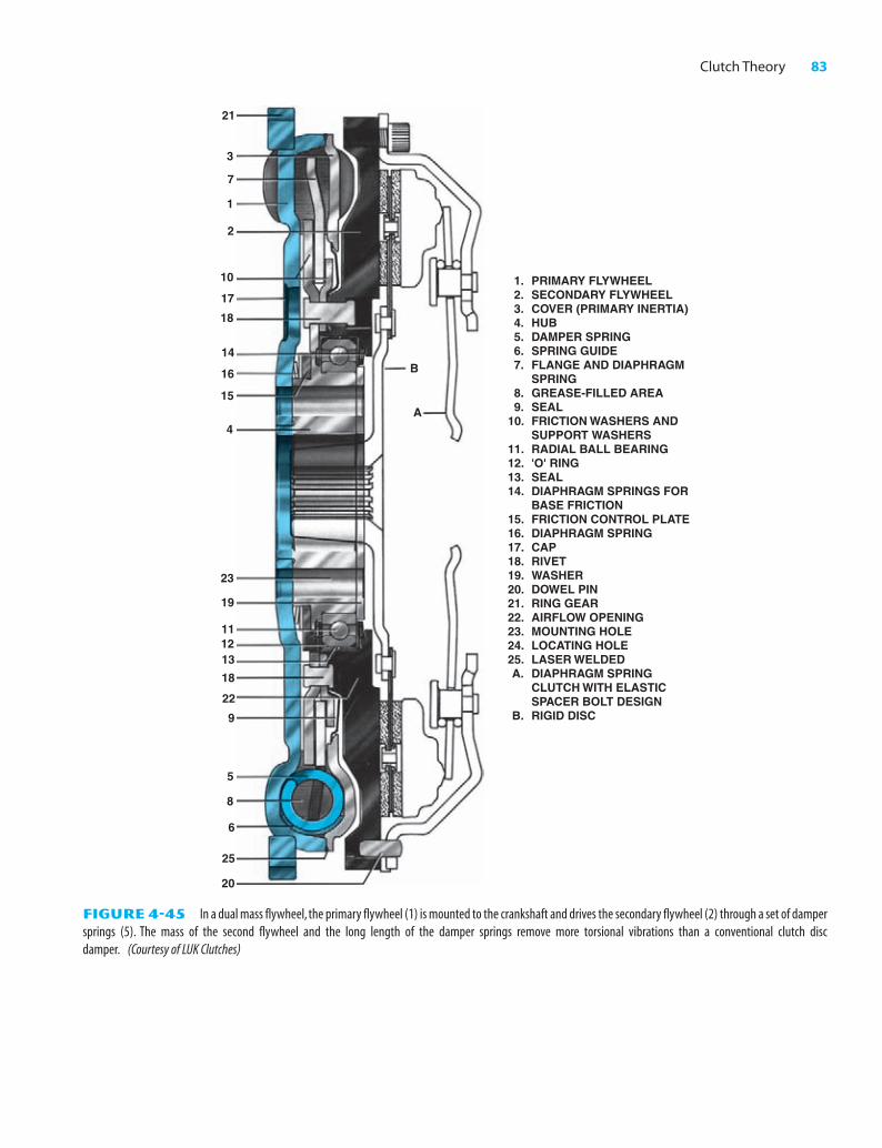
The dual mass flywheel consists of two flywheels: the pri-mary one is bolted to the engine crankshaft, and the secondaryone is mounted on the primary flywheel through a ball bearing(Figure 4-45). The clutch assembly is mounted on the secondaryflywheel, and engine torque must pass from the primary flywheelthrough a set of very long damper springs to the secondary fly-wheel and clutch. Vibration dampening is improved because ofthe very long damper springs, which have a low natural vibrationfrequency, and the mass of the secondary flywheel, which adds tothe mass of the pressure plate and clutch assembly.
M04_BIRC4058_05_SE_C04.QXD 3/29/07 12:04 PM Page 82
Clutch Theory 83
46106 C PH OH A Bi h P N 83 K/PMS DESIGN SERVICES OF
A
B
3
21
7
1
2
10
17
18
14
16
15
4
23
20
25
6
8
5
9
22
18
131211
19
1. PRIMARY FLYWHEEL 2. SECONDARY FLYWHEEL 3. COVER (PRIMARY INERTIA) 4. HUB 5. DAMPER SPRING 6. SPRING GUIDE 7. FLANGE AND DIAPHRAGM SPRING 8. GREASE-FILLED AREA 9. SEAL 10. FRICTION WASHERS AND SUPPORT WASHERS 11. RADIAL BALL BEARING 12. 'O' RING 13. SEAL 14. DIAPHRAGM SPRINGS FOR BASE FRICTION 15. FRICTION CONTROL PLATE 16. DIAPHRAGM SPRING 17. CAP 18. RIVET 19. WASHER 20. DOWEL PIN 21. RING GEAR 22. AIRFLOW OPENING 23. MOUNTING HOLE 24. LOCATING HOLE 25. LASER WELDED A. DIAPHRAGM SPRING CLUTCH WITH ELASTIC SPACER BOLT DESIGN B. RIGID DISC
FIGURE 4-45 In a dual mass flywheel, the primary flywheel (1) is mounted to the crankshaft and drives the secondary flywheel (2) through a set of dampersprings (5). The mass of the second flywheel and the long length of the damper springs remove more torsional vibrations than a conventional clutch discdamper. (Courtesy of LUK Clutches)
M04_BIRC4058_05_SE_C04.QXD 3/29/07 12:04 PM Page 83

84 CHAPTER 4
46106 C PH OH A Bi h P N 84 K/PMS DESIGN SERVICES OF
Summary
1. A clutch assembly uses a pressure plate and clutch discbolted to the flywheel plus the clutch release mechanism.
2. When the clutch is applied, the pressure plate springssqueeze the clutch disc between the pressure ring andthe flywheel. Releasing the clutch pulls the pressure ringback, compressing the springs.
3. A clutch disc has friction material facings. It uses a mar-cel to help provide smooth clutch application and dampersprings to prevent torsional vibration.
4. A clutch is released when the linkage pushes on the fork,forcing the release bearing against the pressure plate re-lease levers.
5. Clutch linkage can be mechanical, using rods and leversor a cable or hydraulics.
Review Questions
1. The clutch is ___________ to allow the driver to select the ap-propriate gear range.
2. The ___________ ___________ describes the relative amountof friction between two surfaces.
3. The clutch disc ___________ reduces the torsional vibrationsfrom the engine.
4. The clutch disc may contain ___________, which is a knowncancer-causing material.
5. The clutch disc facing is attached to the ___________ part ofthe clutch disc by rivets.
6. The ___________ ___________ ___________ bolts to theflywheel.
7. The pressure plate releases the clutch disc when the clutch is___________.
8. The clutch is ___________ when the clutch pedal is depressed.
9. The ___________ ___________ transmits force from theclutch linkage to the spinning pressure plate.
10. The ___________ ___________ supports the end of the trans-mission clutch shaft.
11. Three types of clutch linkage are common. They are:
a. ___________
b. ___________
c. ___________
12. A clutch pedal ___________ is used to prevent the vehiclefrom starting with the clutch engaged.
13. When the clutch pedal is released, the clutch is ___________.
14. A ___________ clutch is commonly used in automotive air-conditioning systems.
15. A multidisc ___________ clutch is commonly used in auto-matic transmissions.
Chapter Quiz
1. When the clutch is applied,
a. springs force the pressure ring toward the clutch cover.
b. springs force the pressure ring toward the flywheel.
c. a substantial pressure exists between the release bearing andthe pressure plate release levers.
d. all of these.
2. Two students are discussing the springs at the center of a clutchdisc. Student A says they are used to help cushion clutch en-gagement. Student B says they absorb engine torsional vibra-tions. Who is correct?
a. Student A
b. Student B
c. Both A and B
d. Neither A nor B
M04_BIRC4058_05_SE_C04.QXD 3/29/07 12:04 PM Page 84

Clutch Theory 85
46106 C PH OH A Bi h P N 85 K/PMS DESIGN SERVICES OF
3. Two students are discussing the marcel portion of a clutch disc.Student A says the lining is riveted to the marcel at one side ofeach wavy portion. Student B says the lining is bonded solidlyto the marcel. Who is correct?
a. Student A
b. Student B
c. Both A and B
d. Neither A nor B
4. When a clutch is released, the (A) release bearing is pushingagainst the release levers; (B) pressure plate springs are com-pressed. Which is correct?
a. A only
b. B only
c. Both A and B
d. Neither A nor B
5. When a clutch is released, (A) the marcel in the disc will flat-ten; (B) an air gap will be on each side of the facing. Which iscorrect?
a. A only
b. B only
c. Both A and B
d. Neither A nor B
6. While discussing clutch lining, Student A says that asbestos lin-ing is no longer used because it is too expensive. Student B saysasbestos lining has been phased out because it presents a healthhazard. Who is correct?
a. Student A
b. Student B
c. Both A and B
d. Neither A nor B
7. Clutch chatter is eliminated by
a. cushion springs at the center of the disc.
b. marcel in the disc.
c. pressure plate springs.
d. none of these.
8. The clutch pedal over-center spring is used to help (A) returnthe clutch pedal to the released position; (B) release the clutch.Which is correct?
a. A only
b. B only
c. Both A and B
d. Neither A nor B
9. In a hydraulic clutch, the slave cylinder (A) is connected to theclutch pedal; (B) is pushed by fluid pressure. Which is correct?
a. A only
b. B only
c. Both A and B
d. Neither A nor B
10. The weights attached to the release levers of a Long-style clutchare used to (A) increase the clamping pressure on the disc; (B)reduce the amount of effort required for pedal depression.Which is correct?
a. A only
b. B only
c. Both A and B
d. Neither A nor B
11. The amount of torque that a clutch can transmit is determinedby the
a. diameter of the disc.
b. strength of the pressure plate springs.
c. number of discs.
d. all of these.
12. A diaphragm clutch uses (A) three wide-release levers; (B) 12strong coil springs. Which is correct?
a. A only
b. B only
c. Both A and B
d. Neither A nor B
13. The major bearing(s) used with a clutch assembly is (are) the (A)release bearing that is mounted at the front of the transmission;(B) pilot bearing that supports the end of the transmission inputshaft. Which is correct?
a. A only
b. B only
c. Both A and B
d. Neither A nor B
14. Clutch pedal free travel is an adjustment that ensures that the(A) release bearing rides constantly against the pressure plate re-lease levers; (B) clutch is completely engaged. Which is correct?
a. A only
b. B only
c. Both A and B
d. Neither A nor B
15. Of the following, which type of clutch is not commonly used inmodern vehicles?
a. wet clutch
b. dog clutch
c. cone clutch
d. internal expanding shoe clutch
16. The single-disc clutch has a 9-in. outside diameter and uses afacing that is 2 in. wide. The clamp load strength is 300 lb. Howmuch torque can it transmit?
17. During the 4 in. of clutch pedal travel, the pressure plate moves0.100 in. What is the linkage leverage ratio?
M04_BIRC4058_05_SE_C04.QXD 3/29/07 12:04 PM Page 85