![__gloabl__ proc(float *arr,float *brr){ float v; __shared__ float shared[L]; shared[threadIdx.x] = brr[threadIdx.x]; __syncthreads(); if(threadIdx.x!=0){](https://static.fdocuments.net/doc/165x107/56649eeb5503460f94bfc7bd/gloabl-procfloat-arrfloat-brr-float-v-shared-float-sharedl.jpg)
M00-040.00 - Level Indicator (Float) Kit Procedure Guide
9
Doc. No.: M00-040.00 Rev. 07 Page 1 of 9 OPW Fuel Management Systems, 6900 Santa Fe Drive, Hodgkins, IL 60525 708-485-4200 www.opwglobal.com M00-040.00 - Level Indicator (Float) Kit Procedure Guide Part #30-1509-xx: 2-inch Standard Float Kits Part #30-1514-xx: 2-inch Stainless-Steel Float Kits Part #30-1509-AEF: Aqueous Ethanol Float Kit This document describes the weight specification on the enclosed Water Level Indicator, correct range of products that can be used, identifying the Water Level Indicator for its intended product group, compatible fluid products, level indicator(s) installation, level indicator kit part numbers and contents. Product Level vs. Water Level Figure 1 shows how the probe components work together. The Product Level Indicator floats on the gasoline or diesel fuel and registers the overall height of the fuel. You can use the Product Level Indicator with or without a Water Level Indicator. Standard Water Level Indicators feature one of two different ballast weights and are etched to show gasoline or diesel. Stainless-Steel Water Level Indicators are weighted internally and are laser-etched with their specific-gravity value. Because fuel products are less dense than water, Water Level Indicators sink through the product and float on the water. Water height at the product/water boundary can be determined accordingly. Figure 1 - Probe Installation in Underground Tank
Transcript of M00-040.00 - Level Indicator (Float) Kit Procedure Guide

Doc. No.: M00-040.00 Rev. 07 Page 1 of 9
67733 Gross Point Road 900
Santa Fe Dr.
OPW Fuel Management Systems, 6900 Santa Fe Drive, Hodgkins, IL 60525 708-485-4200 www.opwglobal.com
M00-040.00 - Level Indicator (Float) Kit Procedure Guide Part #30-1509-xx: 2-inch Standard Float Kits
Part #30-1514-xx: 2-inch Stainless-Steel Float Kits
Part #30-1509-AEF: Aqueous Ethanol Float Kit
This document describes the weight specification on the enclosed Water Level Indicator, correct range of products that can be used, identifying the Water Level Indicator for its intended product group, compatible fluid products, level indicator(s) installation, level indicator kit part numbers and contents.
Product Level vs. Water Level
Figure 1 shows how the probe components work together.
The Product Level Indicator floats on the gasoline or diesel fuel and registers the overall height of the fuel. You can use the Product Level Indicator with or without a Water Level Indicator.
Standard Water Level Indicators feature one of two different ballast weights and are etched to show gasoline or diesel. Stainless-Steel Water Level Indicators are weighted internally and are laser-etched with their specific-gravity value. Because fuel products are less dense than water, Water Level Indicators sink through the product and float on the water. Water height at the product/water boundary can be determined accordingly.
Figure 1 - Probe Installation in Underground Tank

Doc. No.: M00-040.00 Rev. 07 Page 2 of 9
67733 Gross Point Road 900
Santa Fe Dr.
OPW Fuel Management Systems, 6900 Santa Fe Drive, Hodgkins, IL 60525 708-485-4200 www.opwglobal.com
Instructional Video: “Multi-drop Probe & Sensor Wiring Instructions”
To watch the instructional video “Multi-drop Probe & Sensor Wiring Instructions” that includes detailed instructions for Probe Level Indicator (float) installation and the assembly of the epoxy seal packs, use one of the following:
If you have a smartphone with a QR-code scanner, scan this QR Code
If you are viewing this manual on a PC or laptop click this link:
Muti-drop Probe and Sensor Wiring Instructions
The instructional video can also be found at www.YouTube.com by entering the search word “OPWGlobal.”
Installing the Level Indicator(s)
Figure 2 - Probe Components
The procedure for assembling the probe level indicators (floats) and probe cable is outlined below.
NOTE: If the wrong type of water level indicator is used, it may float to the top and register an
unusually high water level, not register at all or sink too far and register an unusually low water
level. If your product-fluid density does not fit into one of these groups, contact OPW Fuel
Management Systems customer sales department for recommendations.
Doc. No.: M00-040.00 Rev. 07 Page 3 of 9
67733 Gross Point Road 900
Santa Fe Dr.
OPW Fuel Management Systems, 6900 Santa Fe Drive, Hodgkins, IL 60525 708-485-4200 www.opwglobal.com
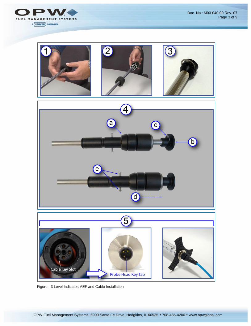
Figure - 3 Level Indicator, AEF and Cable Installation
Doc. No.: M00-040.00 Rev. 07 Page 4 of 9
67733 Gross Point Road 900
Santa Fe Dr.
OPW Fuel Management Systems, 6900 Santa Fe Drive, Hodgkins, IL 60525 708-485-4200 www.opwglobal.com
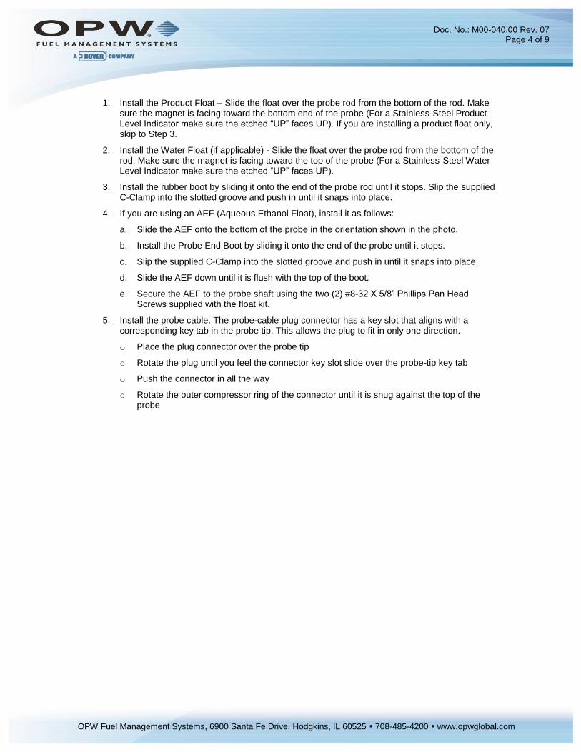
1. Install the Product Float – Slide the float over the probe rod from the bottom of the rod. Make sure the magnet is facing toward the bottom end of the probe (For a Stainless-Steel Product Level Indicator make sure the etched “UP” faces UP). If you are installing a product float only, skip to Step 3.
2. Install the Water Float (if applicable) - Slide the float over the probe rod from the bottom of the rod. Make sure the magnet is facing toward the top of the probe (For a Stainless-Steel Water Level Indicator make sure the etched “UP” faces UP).
3. Install the rubber boot by sliding it onto the end of the probe rod until it stops. Slip the supplied C-Clamp into the slotted groove and push in until it snaps into place.
4. If you are using an AEF (Aqueous Ethanol Float), install it as follows:
a. Slide the AEF onto the bottom of the probe in the orientation shown in the photo.
b. Install the Probe End Boot by sliding it onto the end of the probe until it stops.
c. Slip the supplied C-Clamp into the slotted groove and push in until it snaps into place.
d. Slide the AEF down until it is flush with the top of the boot.
e. Secure the AEF to the probe shaft using the two (2) #8-32 X 5/8” Phillips Pan Head Screws supplied with the float kit.
5. Install the probe cable. The probe-cable plug connector has a key slot that aligns with a corresponding key tab in the probe tip. This allows the plug to fit in only one direction.
o Place the plug connector over the probe tip
o Rotate the plug until you feel the connector key slot slide over the probe-tip key tab
o Push the connector in all the way
o Rotate the outer compressor ring of the connector until it is snug against the top of the probe

Doc. No.: M00-040.00 Rev. 07 Page 5 of 9
67733 Gross Point Road 900
Santa Fe Dr.
OPW Fuel Management Systems, 6900 Santa Fe Drive, Hodgkins, IL 60525 708-485-4200 www.opwglobal.com
Product Density and Chemical Compatibility of Standard Level Indicators (Floats)
Product Group Compatibility API Specific Gravity
Gasoline
Gasoline Aviation Gasoline Regular Unleaded Regular Leaded Premium Unleaded Gasoline/Methanol blend, less than 5% methanol Gasohol, less than 40% ethanol
45 < API < 78 0.68 < d < 0.80
Diesel
Diesel Jet Fuel Kerosene Motor Oil Toluene Gear Oil Transmission Oil
26 < API < 45 0.80 < d < 0.90
NOTE: If the level indicator is used in a non-compatible fluid, swelling, cracking and dissolving
may occur, leading to level-indicator failure. If your product is not chemically compatible with the
level indicators, contact OPW Fuel Management Systems Customer Service for
recommendations.
Determining Product Group for a Standard Water Level Indicator
Figure 4 - Determining Type of Standard Water Level Indicator
Standard Water Level Indicators feature one of two different ballast weights and are etched for gasoline or diesel (See Figure 4). This weight allows the level indicator to sink through the product, but to float on the water. This registers the height of the water at the product/water boundary. The weight is certified by OPW Fuel Management Systems for use with one of two product groups, the gasoline group OR the diesel group. There is a mark etched on the ballast weight plate ("g" for gasoline, "d" for diesel). The water float for gas also has a white outer ring while the water float for diesel is black.
Stainless-Steel Water Level Indicators are weighted internally and are laser-etched with their specific-gravity rating.

Doc. No.: M00-040.00 Rev. 07 Page 6 of 9
67733 Gross Point Road 900
Santa Fe Dr.
OPW Fuel Management Systems, 6900 Santa Fe Drive, Hodgkins, IL 60525 708-485-4200 www.opwglobal.com
Waterproof Electrical Connections
To watch the instructional video “Multidrop Probe & Sensor Wiring Instructions” that includes detailed instructions for the assembly of the Epoxy packs, use one of the following:
If you have a smartphone with a QR-code scanner, scan this QR Code:
If you are viewing this manual on a PC or laptop click this link
Click Here for the Waterproof Electrical Connections Video
The instructional video can also be found at www.YouTube.com by entering the search word “OPWGlobal.”
The procedure for assembling the wire connections and resin sealpacks is outlined below.
Safety Information
Contains vinyl cyclohexene dioxide. Harmful if swallowed. Do not get product on skin or in eyes. Do not inhale fumes.
For detailed product hazard information see the MSDS for the 3M™ Scotchcast 3570G-N (Parts A & B). Use one of the following, go to the Documents tab and select the MSDS:
If you have a smartphone with a QR-code scanner, scan this QR Code:
Or go to this link MSDS - Scotchcast 3570G-N (Parts A & B)

Doc. No.: M00-040.00 Rev. 07 Page 7 of 9
67733 Gross Point Road 900
Santa Fe Dr.
OPW Fuel Management Systems, 6900 Santa Fe Drive, Hodgkins, IL 60525 708-485-4200 www.opwglobal.com
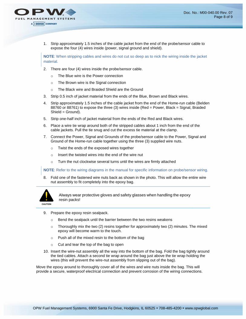
Figure 5 - Assembling the Epoxy Sealpack for Waterproof Electrical Connections
It is VERY important to seal all probe and sensor connections in the junction box to prevent corrosion of the wires.
To make the connections waterproof, use the supplied SCOTCHCAST™ epoxy-resin Insulating Resin Sealpacks. They are provided to seal the electrical connections from moisture and water, and prevent corrosion of the connections. Install one for each cable connection.
Doc. No.: M00-040.00 Rev. 07 Page 8 of 9
67733 Gross Point Road 900
Santa Fe Dr.
OPW Fuel Management Systems, 6900 Santa Fe Drive, Hodgkins, IL 60525 708-485-4200 www.opwglobal.com
1. Strip approximately 1.5 inches of the cable jacket from the end of the probe/sensor cable to expose the four (4) wires inside (power, signal ground and shield).
NOTE: When stripping cables and wires do not cut so deep as to nick the wiring inside the jacket
material.
2. There are four (4) wires inside the probe/sensor cable.
o The Blue wire is the Power connection
o The Brown wire is the Signal connection
o The Black wire and Braided Shield are the Ground
3. Strip 0.5 inch of jacket material from the ends of the Blue, Brown and Black wires.
4. Strip approximately 1.5 inches of the cable jacket from the end of the Home-run cable (Belden 88760 or 88761) to expose the three (3) wires inside (Red = Power, Black = Signal, Braided Shield = Ground).
5. Strip one-half inch of jacket material from the ends of the Red and Black wires.
6. Place a wire tie wrap around both of the stripped cables about 1 inch from the end of the cable jackets. Pull the tie snug and cut the excess tie material at the clamp.
7. Connect the Power, Signal and Grounds of the probe/sensor cable to the Power, Signal and Ground of the Home-run cable together using the three (3) supplied wire nuts.
o Twist the ends of the exposed wires together
o Insert the twisted wires into the end of the wire nut
o Turn the nut clockwise several turns until the wires are firmly attached
NOTE: Refer to the wiring diagrams in the manual for specific information on probe/sensor wiring.
8. Fold one of the fastened wire nuts back as shown in the photo. This will allow the entire wire nut assembly to fit completely into the epoxy bag.
Always wear protective gloves and safety glasses when handling the epoxy resin packs!
9. Prepare the epoxy resin sealpack.
o Bend the sealpack until the barrier between the two resins weakens
o Thoroughly mix the two (2) resins together for approximately two (2) minutes. The mixed epoxy will become warm to the touch.
o Push all of the mixed resin to the bottom of the bag
o Cut and tear the top of the bag to open
10. Insert the wire-nut assembly all the way into the bottom of the bag. Fold the bag tightly around the tied cables. Attach a second tie wrap around the bag just above the tie wrap holding the wires (this will prevent the wire-nut assembly from slipping out of the bag).
Move the epoxy around to thoroughly cover all of the wires and wire nuts inside the bag. This will provide a secure, waterproof electrical connection and prevent corrosion of the wiring connections.

Doc. No.: M00-040.00 Rev. 07 Page 9 of 9
67733 Gross Point Road 900
Santa Fe Dr.
OPW Fuel Management Systems, 6900 Santa Fe Drive, Hodgkins, IL 60525 708-485-4200 www.opwglobal.com
Kit Part Numbers and Contents
Item and Part Number
Kit Number
30
-15
09
-AE
F
30
-15
09
-01
30
-15
09
-02
30
-15
14
-01
30
-15
14
-02
30
-15
14
-03
Aqueous Ethanol Float (AEF) (20-4430) X
Product level indicator assembly 2-inch (30-0125) X X X
Water level indicator assembly, 2-inch gas (30-0126) X
Water level indicator assembly 2-inch Diesel (30-0119) X
Stainless-Steel Product SG .70 min (30-0109) X X X
Stainless-Steel Water SG .85 min (30-0108) X
Stainless-Steel Water SG .92 min (30-0107) X
Cable, 3-pole, 22-gage, 6-ft., Blue (10-1185) X X X X X X
Cable Tie (280-014) x2 X X X X X X
Seal Pack (390008) X X X X X X
Probe-End Boot (50-3092) X X X X X
AEF Probe Boot (50-3243) X
5/8” External Retaining Ring (50-0151) X X X X X X
Level Indicator Manual (M00-040.00) X X X X X X
The product float for LPG is not certified for applications in which it will be subjected to pressures at or above 300PSI. Pressures higher than 300PSI will damage the device, preventing it from providing accurate measurements.