Patented Completion Technology Geoslicing © Enhanced Oil and Gas Recovery Technology.

SLURRYMINDER:A Rational Oil Well Completion Design ModuleE. Brent Kelly, Philippe Caillot, Robert Roemer, and Thierry Simien,Dowell Schlumberger
A critical phase of oil well completion involves positioning cementbetween the outer surface of a metal casing and the sides of the well.This task is done by injecting a specially formulated cement slurrydown the center of the casing and up the sides of the bore hole. De-signing these slurry systems is time consuming and expensive be-cause of the variability of the conditions between wells and the vari-ability of the raw materials and techniques used in geographicallydiverse locations. SLURRYMINDER is a design tool to aid field engi-neers in creating globally consistent cement slurry formulations andto rapidly disseminate current well-cementing techniques. We de-scribe the implementation of this system and why AI technology wasused; we also discuss corporate benefits of the system, both real andprojected. We provide details on the SLURRYMINDER developmentprocess, its worldwide deployment, and our experiences in maintain-ing and updating it.
From: IAAI-92 Proceedings. Copyright © 1992, AAAI (www.aaai.org). All rights reserved.

Problem DescriptionA critical phase of oil or gas well completion involves positioning ce-ment within the well annulus by pumping a specially designed cementslurry down the well casing and up the sides of the bore hole, as shownin figure 1 and discussed by Nelson (1990). A typical cement slurry iscomposed of the cement powder, some type of mix water (usually fresh
194 KELLY, ET AL.
AAAAAAAAAAAAAAAAAAAAAAAAAAAAAAAAAAAAAAAA
AAAAAAAAAAAAAAAAAAAAAAAAAAAA
AAAAAAAAAAAAAAAAAAAAAAAAAAA
AAAAAAAAAAAAAAAAAAAAAAAAAAAAAAAAAAAAAAAAAAAAAAAAAAAAAAAAAAAAAAAAA
AAAAAAAAAAAAAAAAAAAAAAAAAAAAAAAAAAAA
AAAAAAAAAAAAAAAAAA
AAAAAAAAAAAAAAAAAAAAAAAAAAA
AAAAAAAAAA
AAAAAAAAAAAAAAAAAA
AAAAAAAAAAAAAAAAAAAAAA
AAAAAAAAAAAAAAAAAA
AAAAAAAAAAAAAAAA
AAAA
A A
A AA
AAAA
AAAAAAAAAAAAAAA
AAAAAAAAAAAAAAA
AAAAAAAAAAAAAAAAAAAAWATER
OIL
OIL
GAS
PRODUCTIONCASING
INTERMEDIATECASING
HIGH PRESSUREGAS
SURFACE CASING
FRESH WATER
CONDUCTORCASING
AA
AAAA
AAAA
WaterBrine
Set Cement
GasOil
Oil Well Cementing
Figure 1. A Schematic Showing How Oil and Gas Wells Are Cemented.Cement slurry is pumped down the inside of the metal casing and up the annu-lus formed by the outer surface of the casing and the sides of the well bore hole.

water or seawater), and one or more chemical additives that give thecement certain specified physical properties during pumping and af-terward when set.
Designing a cement slurry system is generally iterative in nature: Aninitial design is proposed, which is then followed by a series of labora-tory testing and tuning steps, as in figure 2. During this testing-tuningprocess, additive concentrations can be modified or certain additivesreplaced by others until the slurry and the set cement satisfy the re-quired physical properties, whereupon it is ready to be pumped into aclient’s well.
Ideally, given similar well conditions anywhere in the world, slurrydesigns should contain similar additives at similar concentration levels.In practice, because of the variability in the cement powder, the qualityof the local additives, and local cementing tradition, slurries designedfor similar well conditions often bear little resemblance to one anoth-er. This dissimilarity not only can be a source of confusion to clients,but from a global research and engineering perspective, it also makesit difficult to disseminate new cementing additive technology.
To address the slurry design problem, Dowell Schlumberger’s engi-neering personnel embarked on an ambitious program to create a slur-ry design support tool. Our goals in developing this tool were twofold:(1) to ensure worldwide design consistency and quality but allow therequired freedom for local practitioners and (2) to create a distribu-tion mechanism for rapid information dissemination of an ever-evolv-ing technology. Earlier work in designing entire cement jobs had al-ready been done by practitioners, such as Wolsfelt, Roger, and Fenoul(1989); however, in their CEMENTEX system, no attempt was made to de-sign the critical cement slurry systems that are actually pumped intothe well.
Prior to investigating a solution to the slurry design problem usingAI techniques, earlier attempts to solve the problem were made usingstatistical regression analysis and material characterization studies. Re-searchers tried to analyze existing field-design data to develop correla-tions between slurry performance properties and the amount of eachchemical additive in the slurry mixture. Unfortunately, because of thevariability in the local cement and chemical additives, the deviation inthe regression parameters was so large that the parameters had no realsignificance, and these efforts failed. Our field engineers and laborato-ry technicians were, however, successfully designing cement slurry for-mulations daily, and we became convinced that an AI approach was theonly feasible alternative remaining if we wanted to achieve a solution tothis problem.
SLURRYMINDER 195

Application DescriptionBy nature, successful cement slurry design is a fuzzy domain whereheuristic information and experience about cement and additive use isrequired. Compounding the problem is the fact that some of theheuristics change depending on geographic location: Design experi-
196 KELLY, ET AL.
API STANDARDS
AA
A
AAAAAA
AAAAAAAAAA
CEMENT
ADDITIVES
Initial Slurry Formulation Estimation
LaboratoryTesting
Slurry Formulation
Tuning
Slurry Preparation
MIXWATER
AAAAAAAAAAAAAAAAA
AAAAAAAAAAA
Slurry Formulation Process
Figure 2. The Cement Slurry Formulation Process.An inital design is formulated and given to the laboratory personnel. This de-sign is mixed in the laboratory, and a series of standard tests defined by theAmerican Petroleum Institute are run on the resulting slurry. If the requiredslurry physical properties are not achieved, the slurry formulation is tuned bymodifying the concentration of one or more of the chemical additives. Thistuned slurry formulation is then mixed, and the tests are rerun. This testingand tuning loop continues until the slurry satisfies the performance parameters,as specified by the client or the sales engineer.

ence in one field location might not be valid in another. As these prob-lem characteristics became known to the development team, we con-cluded that solving the slurry design problem would likely require theuse and integration of an extensive amount of information from a vari-ety of sources. Having had significant experience within Schlumbergerusing AI techniques, we knew many of the risks and benefits associatedwith these technologies and opted to approach the solution to ourproblem through the creation of an imbedded knowledge-based sys-tem.
Development ConstraintsWhile designing and implementing SLURRYMINDER, we were requiredto work under several existing constraints.
Distributed expertise and varying methodology: Our cement slurrydesign specialists were distributed all over the world, as illustrated infigure 3. Although they were all experts in their own region, their de-sign methodology and design experiences were somewhat different. Torationalize these various points of view, one specialist at the engineer-ing center in St. Etienne, France, was appointed knowledge czar, with
SLURRYMINDER 197
Figure 3. Cementing Specialists Who Assisted with SLURRYMINDER DevelopmentWere Located All over the World.Primary specialists involved throughout the development process were located inDenver, Colorado; Aberdeen, Scotland; and St. Etienne, France. Additional ex-perts providing input were stationed in Singapore; Oklahoma City, Oklahoma;and Houston, Texas.

the responsibility of converging methodologies and making strategicdecisions when conflicting opinions arose.
Off-the-shelf software tools: Funding and timing constraints wouldnot allow us the luxury of creating a custom expert system shell or de-veloping a custom human interface tool. Hence, we were required touse software tools that were available in the software marketplace.
Existing design data: At all company locations, a cement slurry de-sign database exists as a repository for successful slurry formulationdata. We wanted to somehow incorporate the use of this local databaseinto SLURRYMINDER so that the global methodology could be made toapply in each locality.
Computer hardware specification: In the mid-1980s, each of our 155field locations purchased a MICROVAX II with a VT-240/241 semigraphicdisplay. To effectively use this investment, SLURRYMINDER was requiredto execute on the existing field computer hardware. The implication ofthis decision was that the interface had to be character based.
Shell Selection CriteriaPrior to selecting a shell for use in constructing SLURRYMINDER, we per-formed a domain analysis to determine which kinds of knowledge wereto be represented. Using this domain information and making somepragmatic decisions, we formulated the following selection criteria thatwe used in the evaluation and selection process:
First, it must support knowledge representation paradigms, includ-ing a robust inference engine that allows both forward- and backward-chaining production rules and an object-oriented schema system thatsupports multiple inheritance. The schema system must be well inte-grated with the inference engine pattern matcher so that the rules caneffectively use the objects, slots, and slot values in their antecedent orconsequent parts.
Second, it should support the concept of multiple knowledge bases,allowing knowledge decoupling and grouping.
Third, it must support the integration of user-defined procedures,functions, or routines in both the left- and right-hand sides of produc-tion rules (which implies calling-out functionality).
Fourth, it must be able to be embedded within a larger software sys-tem or program (which implies calling-in functionality).
Fifth, it must provide a development environment with the followingminimum capabilities: dynamic rule and object creation through ruleand object editors; browsing features to examine rules and objectswithin the knowledge base, including progeny graphs, rule-networkgraphs, and textual listings of rules and objects; breakpoints to control
198 KELLY, ET AL.

rule execution; and tracing features to observe rule behavior andknowledge base modification during execution.
Sixth, it must provide a small run-time kernel that can be used to ex-ecute systems created with the shell without the development environ-ment present. In this run-time environment, system performanceshould improve.
Seventh, it must support a run-time kernel that does not require abit-mapped graphics terminal or additional software packages to exe-cute properly. The human interface should be determined by the ap-plication developers and not the selected shell.
Eighth, it must execute on a variety of hardware platforms, withknowledge bases requiring only minor modifications when changingplatforms.
Ninth, it must have a significant user community to ensure its robust-ness and reliability.
Tenth, it must be able to operate in conjunction with future acquisi-tion and design software written in C.
Eleventh, it must be accompanied by clearly written and profession-ally typeset documentation. This documentation should be written sothat individuals reasonably familiar with software development can un-derstand how to use the shell without having to ask for undocumentedfunctions and features.
Twelfth, it must be priced so that development copies can readily bepurchased by the company’s engineering centers. The run-time versionmust be priced so that a worldwide license can be obtained economi-cally.
Thirteenth, it must be able to be called by an Ada program or belinked with Ada program modules.
Fourteenth, it must allow communication with an INGRES databasethrough query facilities within the shell or through the calling-out–call-ing-in functions.
In addition, the company or organization marketing the selectedshell must do the following:
First, it must provide a hotline service staffed by qualified profession-als available to answer questions regarding use of the shell. A fee canbe charged for this service.
Second, it must be able to provide training either in house or at a re-mote location to teach individuals how to use the tool. A fee can becharged for this service.
Third, it must be reputable, with at least five years of experience indeveloping expert system shells or other AI software.
During the selection process, we evaluated three C-based expert sys-tem shells; our final choice was NEXPERT OBJECT from Neuron Data.
SLURRYMINDER 199

System DesignA simple representation of the SLURRYMINDER architecture is shown infigure 4. The application consists of five distinct parts: (1) human in-terface routines; (2) utilities for system configuration, browsing ofother useful online databases, and a slurry pricing spreadsheet; (3) thereasoning mechanism for generating the list of chemical additives re-quired in the slurry formulation; (4) the explanation and warning sub-system used to explain why a particular formulation was generated andwhether there are any warnings on how to use one or more of the addi-tives in the formulation; and (5) the query and calculation routines forgenerating additive concentrations and the quantities required for lab-oratory testing.
Knowledge Base Decomposition and Design. In attempting to create amodel of how our specialists approach the slurry design problem, webecame aware of four distinct levels of abstraction in their thinkingprocesses: (1) recognition of which type of slurry system must be gen-erated to satisfy the required performance parameters, (2) recognitionbased on the chemical product family that can be used in the slurry sys-tem, (3) an evaluation of whether a particular chemical family is actual-ly required in the formulation, and (4) the actual selection of one ormore of the chemical additives from a particular family that enablesthe slurry to meet one or more of the specified performance parame-ters.
Knowledge within SLURRYMINDER was decomposed into 14 separateknowledge bases, 1 knowledge base for general or kernel knowledgeand the others for specific knowledge relative to one particular chemi-cal additive family. Abstraction levels one through three are containedin the kernel knowledge base, but level four is contained within theknowledge base for each particular family, as in figure 5. Representingthe current level of knowledge requires approximately 115 classes andobjects and over 700 rules, with several C routines used for optimizingdynamic object creation during inferencing.
When a user queries SLURRYMINDER for a slurry formulation, the rea-soning mechanism uses a backward-chaining, depth-first search strate-gy. We implemented an exhaustive searching strategy so that multipletypes of designs can be obtained if applicable, with each type of designpotentially having multiple formulations. During inferencing, compet-ing slurry formulations are ranked according to a simple model basedon how well a particular additive will perform in a given situation.Users can limit the number of solutions that are generated by SLURRY-MINDER, which in certain instances can grow geometrically with thenumber of selectable additives at each formulation stage.
200 KELLY, ET AL.

We designed the knowledge base so that each chemical additive fam-ily is self-validating about its applicability in a given design problem.When a family determines that its functions are required in slurry for-mulation, it sends a selection message to each individual chemical ad-ditive within the family. Individual additives are also self-validating;when they receive the selection message from their parent object, rulesare evaluated to determine if the particular additive can be selectedgiven the current state of the formulation and the global design pa-
SLURRYMINDER 201
Which system type to design?
Conventional Foam Salt Gas Migration
1. Extender2. Weighting Agent3. Fluid Loss4. Accelerator5. ... Additional Families .....
[...]
Level 1
Level 2
FoamSaltbond
ArcticsetLatex
AntifoamStrength Ret.
Lost CirculationDispersant
Retarder
Accelerator
Fluid Loss
Weighting Agent
Extender KBEXTENDER
selected?
D020
D128
D124
D079
Level 4
AdditiveFamily
Needed?
Kernel Knowledge Base
Message
Message
Level 3
Figure 4. Simple Schematic of the SLURRYMINDER Architecture.Five separate subsystems are connected by a set of system kernel routines: thehuman interface, the inferencing mechanism, the concentration routines, the ex-planation and warning subsystem, and some utility routines for database brows-ing and administration. Within the inferencing mechanism, there are 14knowledge bases containing over 700 separate rules and solution strategies.

rameters, such as well temperature or depth.As additives are selected for use, they append an explanation code
and a warning code to the current intermediate solution node, as illus-trated in figure 6. These codes can then be used by the explanationand warning subsystem to extract context-specific explanation or warn-
202 KELLY, ET AL.
Which system type to design?
Conventional Foam Salt Gas Migration
1. Extender2. Weighting Agent3. Fluid Loss4. Accelerator5. ... Additional Families .....
[...]
Level 1
Level 2
FoamSaltbond
ArcticsetLatex
AntifoamStrength Ret.
Lost CirculationDispersant
Retarder
Accelerator
Fluid Loss
Weighting Agent
Extender KBEXTENDER
selected?
D020
D128
D124
D079
Level 4
AdditiveFamily
Needed?
Kernel Knowledge Base
Message
Message
Level 3
Figure 5. Knowledge-Abstraction Levels within SLURRYMINDER.Level 1 determines which type of system to design. Level 2 is a declarative level,indicating which additive families might be included in a particular systemtype. Level 3 is activated by a message from level 2. Level 3 determines if the ef-fect of a particular additive family is required given the input data and the ad-ditives already selected. If the effect of an additive family is needed, level 3 sendsa message to level 4, which contains the selection knowledge for each particularadditive in the family. Levels 1, 2, and 3 are contained within the kernelknowledge base, and level 4 is divided into 13 separate knowledge bases, one foreach additive family.

ing messages from a flat-file database specific to the additive in ques-tion; thus, users are informed about why a particular additive was se-lected in a given situation. It is this explanation and warning systemthat provides the mechanism for rapid technology transfer within SLUR-RYMINDER. When new chemical products are added to the SLURRYMIN-DER knowledge base, they appear in the ranked formulations they ob-tain from the reasoning mechanism. After a particular slurryformulation is generated, the user can invoke the explanation andwarning option to view an explanation of how this new additive is to beused. If more information is desired, users can branch using a hot keyto a more complete online Additive Information Manual, giving com-plete technical details for each chemical product.
Previous Design Database Link. Users of the SLURRYMINDER prototypeinformed the development team that slurry formulations without addi-tive concentrations were useless. Linking with the local design databaseis where SLURRYMINDER bridges the gap between a global formulationmethodology and local practice.
Once the additives in a slurry formulation are selected, users havetwo options for generating additive concentrations: a default methodor a query of their own local database, as shown in figure 7. The de-fault method can be likened to browsing a cementing manual for gen-eral recommendations for additive concentrations, independent of thelocal cement and additive quality. Querying a user’s local database,however, provides a connection with previous design history in thesame geographic location.
When users query their local design database, interactions betweenthe local cement and the local chemical additives are implicitly ac-counted for because these previous designs have already been testedsuccessfully in the laboratory. Queries usually consist of some designinput data, such as temperature and density; the targeted physicalproperties of the cement; and additional items for narrowing thesearch, such as the well name or the client name. These criteria areused to build an SQL-like query to search a series of relational tables inthe database. The output of the query consists of the average chemicaladditive concentration value for all tests matching the query criteria,the minimum and maximum values, and the total number of testsfound. Users can review this information and reformulate the query ifnarrower criteria are needed.
Linking with previous design experience through these local databas-es leverages and validates the corporate strategy for a global designmethodology that can be made to apply nearly anywhere in the world. Itis this coupling of expert system technology for selecting the chemical
SLURRYMINDER 203

additives with traditional database search techniques that is makingSLURRYMINDER an outstanding technical success for the company.
Application Use And PayoffSLURRYMINDER was officially released to approximately 155 field loca-tions in 55 countries in October 1991. The system was designed for twodistinct types of users: sales engineers and laboratory technicians. Salesengineers interact with clients to prepare proposals and bids for ser-vices and are usually initially interested only in approximate slurry for-mulations; fine tuning of the bid occurs after the laboratory techni-cians test and tune the slurry to obtain the exact quantities of thechemical additives needed to perform the cementing service. Labora-tory technicians, however, are interested in obtaining an accurate for-mulation for two reasons: They want to (1) lower operating costs by re-ducing the number of expensive testing iterations they must performand (2) increase their throughput. Both types of user are able to ac-complish their goals using SLURRYMINDER.
Although SLURRYMINDER has only been released to our field opera-
204 KELLY, ET AL.
list of additives: [D156, D800, D065, ...]
confidence level: 9.5
explanation codes: [E_CONV_3, E_D156_2, ...]
warning codes: [W_CONV_1, W_D156_2, ...]
additive role: [flac, retarder, dispersant, ...]
DISPERSANT_57
Intermediate Solution Node
Figure 6. Each Intermediate Solution Node Contains the List of Selected Addi-tives to This Point in the Inference and the Total Confidence Level for the Node.Explanation and warning slots contain a list of codes, the first for the type of so-lution the node represents and those following for each selected additive. The roleof each selected additive is also represented. Node names are indicative of thetype of additive most recently selected, with the node number showing the orderin which this node was created.
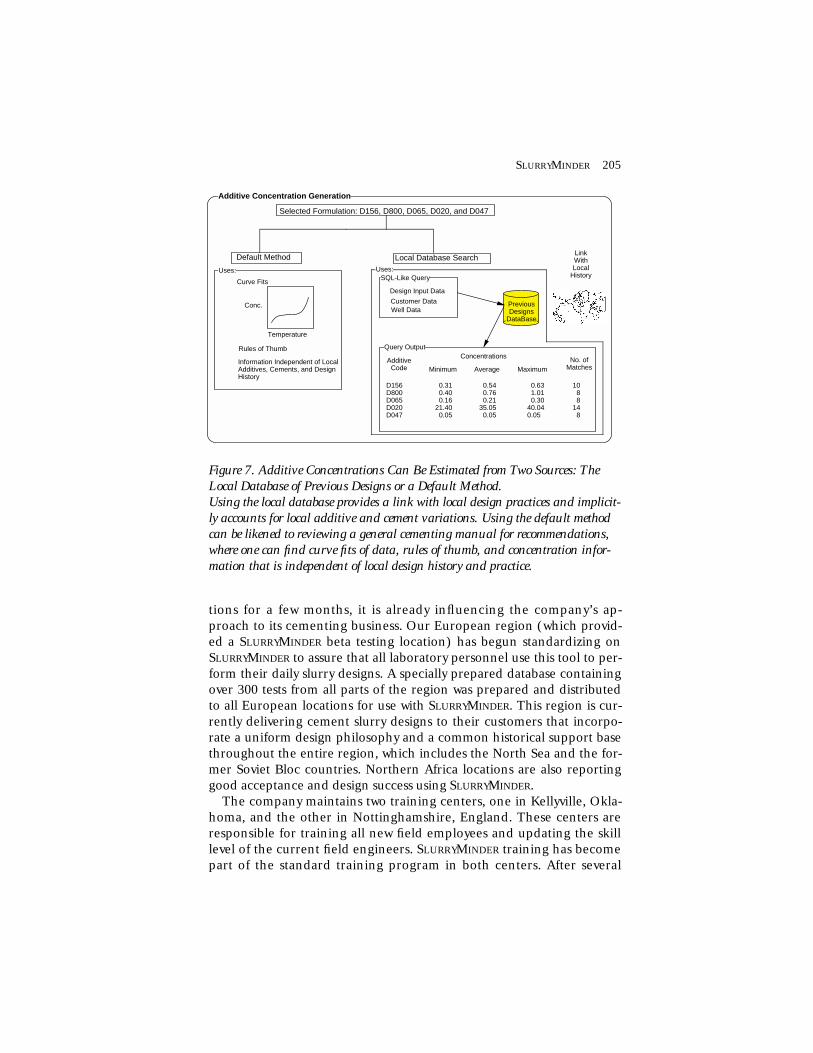
tions for a few months, it is already influencing the company’s ap-proach to its cementing business. Our European region (which provid-ed a SLURRYMINDER beta testing location) has begun standardizing onSLURRYMINDER to assure that all laboratory personnel use this tool to per-form their daily slurry designs. A specially prepared database containingover 300 tests from all parts of the region was prepared and distributedto all European locations for use with SLURRYMINDER. This region is cur-rently delivering cement slurry designs to their customers that incorpo-rate a uniform design philosophy and a common historical support basethroughout the entire region, which includes the North Sea and the for-mer Soviet Bloc countries. Northern Africa locations are also reportinggood acceptance and design success using SLURRYMINDER.
The company maintains two training centers, one in Kellyville, Okla-homa, and the other in Nottinghamshire, England. These centers areresponsible for training all new field employees and updating the skilllevel of the current field engineers. SLURRYMINDER training has becomepart of the standard training program in both centers. After several
SLURRYMINDER 205
Selected Formulation: D156, D800, D065, D020, and D047
Default Method Local Database Search
PreviousDesigns
DataBase
SQL-Like Query
Design Input Data
Customer DataWell Data
Concentrations
Minimum Average MaximumNo. of
MatchesAdditive
Code
D156D800D065D020D047
0.31 0.40 0.1621.40 0.05
0.54 0.76 0.2135.05 0.05
0.63 1.01 0.3040.040.05
10 8 814 8
Query Output
Information Independent of Local Additives, Cements, and Design History
LinkWithLocal
History
Temperature
Conc.
Curve Fits
Rules of Thumb
Uses: Uses:
Additive Concentration Generation
Figure 7. Additive Concentrations Can Be Estimated from Two Sources: TheLocal Database of Previous Designs or a Default Method.Using the local database provides a link with local design practices and implicit-ly accounts for local additive and cement variations. Using the default methodcan be likened to reviewing a general cementing manual for recommendations,where one can find curve fits of data, rules of thumb, and concentration infor-mation that is independent of local design history and practice.

years of this one-time training, a significant portion of our design engi-neers and technicians will have been trained to use SLURRYMINDER, re-sulting in its becoming an integral part of the corporate technicalstructure. Thus, repetitive training costs are reduced, and geographi-cally remote locations gain a technical marketing edge.
Expected BenefitsOn a global basis, we perform approximately 36,000 well-cementationjobs annually and design approximately twice this many. For each ser-vice recommendation made by a sales engineer, we estimate that per-sonnel savings of 1/2 to 1-1/2 person-hours will be achieved, as follows:Sales engineers typically provide design data to laboratory personneland request that the laboratory prepare an estimated slurry formula-tion, without laboratory testing for bidding purposes. This process usu-ally requires approximately 1/2 to 1-1/2 hours for each recommenda-tion from the sales engineer and the laboratory technician. WithSLURRYMINDER, the sales engineer can obtain a good initial slurry for-mulation in less than three minutes without requiring interaction withlaboratory personnel. With a conservative basis of 12,000 formulationsdesigned annually using SLURRYMINDER, we have an annual savings of6,000 to 18,000 person-hours, or 3 to 9 person-years. Intangiblebenefits, such as better slurry designs using updated technology, whichcannot be measured precisely, must also be considered.
Laboratory technicians typically perform an average of four test runsfor each slurry pumped. One of our cementing specialists estimatedthat by using SLURRYMINDER, this number will be reduced by at leastone-fourth. Normally, each laboratory test requires approximately fourto six hours of expensive machine time to run. If SLURRYMINDER is usedto design 12,000 jobs annually, we save worldwide approximately60,000 machine-hours. Internal accounting audits indicate that re-placement parts for the machinery required to run these tests averagesabout US$10 for each test run; hence, savings resulting from lower ma-chine maintenance costs are estimated at US$120,000 annually.
Application Development and DeploymentIn its current form, SLURRYMINDER is the result of a three-year effort insoftware and knowledge engineering. Generating the knowledge basesrepresents only approximately 25 to 30 percent of the total effort re-quired to develop the entire application. Currently, we have investedeight person-years in the project.
206 KELLY, ET AL.

Development ProcessThe SLURRYMINDER development process began in February 1989. Twoengineers were given the responsibility for performing a feasibilityanalysis to determine whether a software tool could be developed tohelp Dowell Schlumberger rationalize and standardize its slurry designefforts on a global basis (figure 8). Earlier efforts at using statisticalmethods to analyze design data to distinguish definite trends in con-junction with raw material characterization studies had failed to pro-vide the tools and the consistency the company was seeking. Hence, webegan looking at expert system techniques to determine if they wouldbe useful in solving our particular problem. Funding for the first yearof the SLURRYMINDER project came from a special fund designed to sup-port projects with high risk but high potential return.
As part of the five-month feasibility analysis, approximately 40 indi-viduals in all parts of the company and at all levels were interviewedthrough a specially prepared questionnaire. These people representedcompany management, slurry design specialists, laboratory technicians,sales engineers, and some new employees with little slurry design expe-rience. Using the results of the questionnaire and some additional in-formation obtained through follow-up interviews, we analyzed our do-main, following suggestions made by Bobrow, Mittal, and Stefik (1986)and using a methodology proposed by Slagle and Wick (1988). Ouranalysis concluded that the slurry design problem could be solvedusing expert system technology, and we recommended that we shouldproceed with prototype development.
The development team was given six months in which to generate aworking prototype that would completely design one type of slurry sys-tem. User specifications and functional specifications for the prototypewere developed in July 1989. We also obtained a portable personal com-puter on which to run our selected development shell for use while weworked with specialists at locations external to the engineering center.Within our company, cementing specialists are in high demand, and wefelt that it would be more economical and convenient if we went tothem rather than require them to come to the engineering center.
In December 1989, the prototype was demonstrated to companymanagement and was accepted. Approval for the development versionof SLURRYMINDER was obtained in January 1990 and was funded fromthe general engineering fund like all other engineering projects.
User specifications for the development version, prepared by corpo-rate marketing and engineering personnel, were received in their finalform in April 1990, and the functional specifications were ready by May1990. Much of the knowledge base design was completed during the
SLURRYMINDER 207

prototyping phase; however, we were required to redesign the humaninterface and incorporate the additional functions into SLURRYMINDER,as required by the user specifications. A global software design was pre-pared during June and July 1990; however, the detailed design of thesoftware proceeded incrementally with the implementation.
SLURRYMINDER alpha testing began in March 1991 and continued forthree months. Our major goal during the alpha test was to ensure thatthe knowledge within SLURRYMINDER was correct and that it would pro-duce good slurry formulations. As part of the alpha test, we prepared aknowledge guide, which is a graphic representation of the design ruleswithin the system, as shown in figures 9 and 10. This knowledge guidecan be thought of as a series of multidimensional flowcharts that canbe used to follow program control during the reasoning process. Usingthe knowledge guide, along with the SLURRYMINDER software, allowedus to obtain 100-percent coverage of the system rules during alpha test-ing. Incidentally, approximately 90 percent of the SLURRYMINDER ruleswere modified as a result of this process, some significantly.
Beta testing began in June 1991 at three locations external to the en-gineering center: Africa Regional Office in Paris, France; European Re-gional Laboratory in Aberdeen, Scotland; and Gulf Coast DivisionalLaboratory in New Orleans, Louisiana. The main goals of this testingwere to ensure that SLURRYMINDER was robust in a field environment and
208 KELLY, ET AL.
Questionnaire Distributionand Evaluation
Knowledge Acquisition
Application Analysis & Evaluation
Prototype Specifications
Prototype Development
Commercial Version User's Specifications
Commercial Version Functional Specifications
Global Software Design
Incremental Detailed Designand Implementation
Beta Testing
Product Maintenance
First Maintenance Release
Prototype Launch Decision
Prototype Acceptance andCommercial Launch Decision
Q1 Q2 Q3 Q4
1989Q1 Q2 Q3 Q4
1990Q1 Q2 Q3 Q4
1991Q1
1992
Alpha Testing
Commercial Product Release
Figure 8. SLURRYMINDER Project Development Timeline.Diamonds represent major milestones achieved in the project development process.

that the human interface was acceptable to real users. Excellent feed-back was obtained during this testing period that resulted in somesignificant modifications to the human interface and the mechanism forgenerating additive concentrations when searching the local database.SLURRYMINDER beta testing was completed and accepted in August 1991,with management approving SLURRYMINDER for worldwide deployment.
SLURRYMINDER 209
Other Systems
Conventional
Right Angle S.
Gas Migration
Other Families
Extender
Latex Stabilizer
Latex
Latex Required
Level 1 - System Identification(Which system(s) to design?)
Level 2 - System Formulation(What additive families may appear
in a particular system?)(Declarative Level)
Level 3 - Family Evaluation(Is the functionality of this
family required in the system?)
Level 4 - Additive Selection(Which additives in this family can be
used given design conditions and previous additives selected?)
System
Formulation
Evaluation
Other Additives
D600
D134
Selection
Flow Chart Types Knowledge Abstraction Levels
AAAAAAAAAAA
AAAAAAA
Dependent Upon
System Context
Dependent Upon FamilyContext
Knowledge Flow Charts
Figure 9. The Structure of SLURRYMINDER’s Multidimensional Flowcharts.Prepared for experts and novices to follow SLURRYMINDER’s reasoning path, eachbox represents an individual flowchart illustrating the conditions required toprove a particular hypothesis. The formulation level is declarative knowledgeand has no explicit validation rules. The structure of these knowledge chartswas designed to reproduce the knowledge-abstraction levels used in designing theknowledge representation scheme. Chart content for levels 2 to 4 is dependent onwhat slurry type was selected at level 1 and how the additive family is usedwithin the selected slurry type.

DeploymentIn September 1991, the SLURRYMINDER executable image and accompa-nying data files were submitted to our corporate baseline managementteam in Tulsa, Oklahoma. This team is responsible for preparing a newcorporate computer baseline every six months and distributing thesoftware therein to all field locations worldwide. Because this mecha-nism was already in place for previously existing software, deploymentto our field locations was straightforward and consisted of copying the
210 KELLY, ET AL.
Latex Selected
D115
BHCT
200 - 250 250 - 300 > 300
Fresh Mixwater
Total Salt < 2.0D115 + D135 Selected
D116
< 200
Total Salt Total Salt >= 2.0 Fresh Mixwater
Total Salt < 2.0< 2.0 >= 2.0
D116 Selected
D116 + D135 Selected
Total Salt < 2.0Total Salt < 2.0
D115 + D135 Selected
D115 + D135 Selected
BHCT
200 - 250 250 - 300
D116 + D135 Selected
D116 + D135 Selected
D116 + D135 Selected
B = 7
B = 10
B = 10
B = 10
B = 10
B = 10
B = 10
B = 7
Figure 10. A Typical Knowledge Chart within SLURRYMINDER at AbstractionLevel 4, Showing Detailed Conditions for Individual Additive Selection.

SLURRYMINDER files into the software baseline, testing the executablefile to ensure that it performed properly in the baseline environment,and distributing a tape.
The user’s manual for SLURRYMINDER was prepared using LATEX, andthe corresponding printable file is contained in the documentationsection of the software baseline. At any time, users in any location canobtain the latest documentation for any product in the software base-line by printing the file on their local printer.
By design, SLURRYMINDER is reasonably easy to use even for novicecomputer users. However, four train-the-trainer training sessions havebeen held; in Tulsa, Oklahoma; Aberdeen, Scotland; Nottinghamshire,England; and St. Etienne, France. Attendees at these training sessionsincluded regional baseline managers, management personnel, trainersfrom our two training centers, sales engineers, and laboratory person-nel. Because of the geographically diverse nature of our company, eachof the individuals attending these training sessions was given the re-sponsibility for training users in their respective regions or locations.
Product MaintenanceWithin our company, software product maintenance is performed bymembers of the software-sustaining section at the engineering centerwhere the product was developed. SLURRYMINDER is now being main-tained by a software engineer who was not a member of the originaldevelopment team. As part of the development effort and good soft-ware engineering practice, the original development team created twodocuments to aid in the maintenance of the SLURRYMINDER software:the SLURRYMINDER Knowledge Base Maintenance Guide and the SLUR-RYMINDER Software Maintenance Guide. These complementary docu-ments respectively describe the internal logic and software structuresof the knowledge bases and the rest of the software in sufficient detailto facilitate maintenance. Coupled with the Knowledge Guide (knowl-edge flowcharts) and the product specification documents, maintain-ers have significant maintenance resources available to them.
Cement slurry design is an evolving domain; we have already begunmodifying the knowledge bases by adding recently developed cement-ing additive products and a new slurry formulation technology to SLUR-RYMINDER. It appears that the architecture of the knowledge bases is wellsuited to domain evolution because these modifications were made byan individual who was not on the original development team. New re-leases of SLURRYMINDER will occur every six months as the company’ssoftware baseline is updated and redistributed to all field locations.
SLURRYMINDER 211

An Example Using SLURRYMINDER
A typical use of the SLURRYMINDER system is illustrated by the followingproblem: A client is drilling an offshore oil well at 12,000 feet belowthe surface. The temperature in the underground formation is approx-imately 235 ˚F, and the slurry density must be around 14.4 pounds to agallon to maintain the hydrostatic head and keep formation fluidsfrom entering the well bore. Because the rig is offshore, seawater willbe mixed with the cement powder to create the cement slurry, and liq-uid chemical additives are preferred over solids because of limited bulkhandling and storage facilities on the rig. The cement slurry must notset up for at least six hours to allow proper placement around the ce-ment casing. This particular cement system must also isolate an adjoin-ing formation with significant potential for gas to enter the cement ma-trix and corrupt the cement, allowing gas to migrate up the casingcolumn and create a potentially dangerous situation. In a well thisdeep, class G well cement will be used; the particular brand availableon location is easy to disperse in the presence of the salt in the seawa-ter. The slurry should have low free water and fluid loss and shouldachieve a good compressive strength in 24 hours.
Design data of this nature are entered into the SLURRYMINDER input
212 KELLY, ET AL.
SlurryMINDER Version 1.1C1
System Functions... Design Slurry Database Utilities...
ADMINISTRATION
Lead EngineerDate RequestedDate RequiredCLIENTRIGWELLSLURRY Ident
:::::::
B. KELLY04/01/9204/03/92SPECIALSP1SP1-1
SPECIAL WELL PROBLEMSGas ZoneJOB TYPE
LinerWELL DATADepthBHSTTemp GradientBHCT
::::
12000 235 1.3 185
ftdeg.Fdeg.F/100ftdeg.F
DESIGN CONSIDERATIONS
Salt RequiredNaCl Amount KCl AmountMixwater TypeCement BrandCement ClassCement TypePref. Blend Mode
::::::::
No
SeaCemoilGETDSLiquid
% BWOW% BWOW
SLURRY PERFORMANCE PARAMETERS
Slurry DensityThickening TimeFluid LossFree WaterComp. Strength
:::::
14.4 6.075.0 3.05000
lb/galhoursmlml/250mlpsi
Slurry Design Input Data Form
Figure 11. SLURRYMINDER’s Primary Data Input Form. Input data consist of well data such as depth, temperatures, and special down-hole conditions; target slurry performance parameters such as density and thick-ening time; properties of the cement; and administration data such as well logis-tical information.

SLURRYMINDER 213
SlurryMINDER Version 1.1C1
System Functions... Design Slurry Database Utilities...Suggested Slurry Designs
Cement Class: G Density: 14.4 lb/gal
BHST: 235 deg.FBHCT: 185 deg.F
RankSolutionType Additive List
11222
GASBLOKGASBLOKGASBLOKGASBLOKGASBLOK
D600 + D135, D128 + D138, D604M, D008, D144, D066D600 + D135, D128 + D138, D604M, D801, D144, D066D600 + D135, D128 + D138, D080, D008, D144, D066D600 + D135, D128 + D138, D145, D008, D144, D066D600 + D135, D128 + D138, D145, D801, D144, D066
Arrow keys move between solutions; <return> key selects a solution
Figure 12. An Example of Slurry Additive Formulations Recommended by SLUR-RYMINDER.Formulations include the list of chemical additives and the rank of each formu-lation. By default, the highest-ranking slurry is highlighted for further process-ing to obtain additive concentrations, explanations, warnings, pricing informa-tion, or a design report.
CONCENTRATIONS
Bulk Cement Properties
Slurry Properties
Mixwater Properties
Laboratory Calculations
ClassSack WeightDry Density
:::
G 94.0 lb174.3 lb/ft^3
TypeDensityBase Fluid
:::
Sea 8.5 lb/gal 5.7 gal/sk
DensityPorosityYield
:::
:::
14.4 lb/gal 63.39 % 1.97 ft^3/sk
Target VolumeCement WeightBase Fluid WtBase Fluid Vol
::::
600.0 ml458.7 g236.9 g231.7 ml
Additive ConcentrationsAdditive Conc. Unit Weight Volume Source Tests Original
Design Data
BHCT185 deg.FBHST235 deg.FDensity 14.4 lb/gal
D600D135D128D138D604MD008D144
3.290.134.101.230.200.280.03
gal/skgal/sk% BWOC% BWOCgal/sk% BWOCgal/sk
136.6 5.7 18.8 5.6 9.9 1.3 1.2
134.0 5.4 7.1 5.9 9.9 1.3 1.2
CemDABECemDABEDefaultDefaultCemDABEDefaultCemDABE
1414 0 0 5 011
g ml
Figure 13. Additive Concentrations Generated by SLURRYMINDER Are Used to Com-pute Quantities Required to Prepare the Slurry Formulation in the Laboratory.Additional calculations are performed to obtain the quantity of water to use andthe volume of slurry obtained from one sack of cement.

data form, as illustrated in figure 11. A series of data checks designedinto the intelligent interface ensure that data entered in the fields areinternally consistent. Prior to invoking the inference engine, users canspecify the maximum number of solutions they would like to obtain;the default is five. This number is used internally during inferencing toprune branches from the search space; only the top candidate solu-tions are kept for subsequent inferencing.
We intentionally designed the inferencing mechanism to be a blackbox as far as users are concerned. Input data are volunteered to the in-ference engine, and little interaction with the user is required until theinference is complete, and the solutions have been generated.
Figure 12 illustrates the output obtained by inferencing using thedata from figure 11. Five solutions were requested, with two of the solu-tions ranked equally as the best. Careful examination reveals that onlysubtle differences exist between the different solutions in this example;however, the different internal chemical additive codes have greatsignificance to the field personnel in terms of how well these additivesperform in different circumstances. Additives joined by a plus sign in-dicate that the first additive requires the aid of the second to providethe required functions in the slurry formulation.
After selecting one of the formulations for further processing, users
214 KELLY, ET AL.
Slurry Options For Selected Slurry
Browse CemDABE Concentrations... Explanations Price/Cost Report Warnings
Current Suggested Slurry Formulation
D600 + D135, D128 + D138, D604M, D008, D144, D066
EXPLANATIONSA "GASBLOK" system is considered in this context because:1 - of a Gas Zone in the well2 - BHCT is between 70F and 375F3 - slurry denstiy is between 12ppg and 20ppg4 - the total concentration of salt in the system is below 15%
A LATEX additive is always needed in a GASBLOK system, it providesfluid loss control and gas migration control:
D600 used with D135, is recommended as LATEX in a GASBLOK system at BHCT below 200F and with 2% or more salt in the system (4% D135 by Volume of Latex)
An EXTENDER is needed because the denstiy is below 15.6 ppg (fora class G cement):
Figure 14. An Example of the Type of Explanations Generated during a Sessionwith SLURRYMINDER. Each explanation includes information on the criteria used to select what type ofslurry to design, why a particular additive family is necessary in the formula-tion, and what the selection conditions are for each individual additive.

have the option of generating additive concentrations, viewing expla-nations or warnings, generating a design report, or obtaining pricinginformation for the particular formulation. Figure 13 illustrates the re-sults obtained from invoking the concentration generation mecha-nism, and figure 14 shows the initial explanation output screen ob-tained from the explanation and warning subsystem.
AcknowledgmentsWe would like to thank the many individuals within the Dowell Schlum-berger organization for their time and efforts, so freely given to makethis project a success. We also want to express our appreciation to ReidSmith of the Schlumberger Laboratory for Computer Science for re-viewing drafts of this manuscript and providing insightful suggestions.
ReferencesBobrow, D. G.; Mittal, S.; and Stefik, M. J. 1986. Expert Systems: Perilsand Promise. Communications of the ACM 29(9): 880–894.
Nelson, E. 1990. Well Cementing. Houston, Texas: Schlumberger Edu-cational Services.
Slagle, J. R., and Wick, M. R. 1988. A Method for Evaluating CandidateExpert System Applications. AI Magazine 9(4): 44–53.
Wolsfelt, G. C.; Roger, C.; and Fenoul, R. 1989. A Cementing JobPreparation Advisor System. Presented at the Sixty-Fourth AnnualTechnical Conference and Exhibition of the Society of Petroleum En-gineers, San Antonio, Tex., 8–11 October.
SLURRYMINDER 215

216 PARKER AND SPANGLER

SLURRYMINDER
SLURRYMINDER 191