
M 43 C FCT 12 2009.qxd:Layout 1
12
M43C Low Emission Engine
Transcript of M 43 C FCT 12 2009.qxd:Layout 1
M 43 CLow Emission Engine
M_43_C_FCT_12_2009.qxd:Layout 1 05.02.2010 10:35 Uhr Seite 1

2
combustion. For IMO I only a small Millereffect of 5% was utilised, however, IMO IIrequires a Miller effect of 20%. This is abig challenge for the turbo charger, whichhas to provide boost ratios of 5 in order tomaintain today’s Mean Effective Pressure(BMEP) values.
By combining increased compressionratio and the Miller effect, NOx emissionscan be reduced by around 30% withoutsacrificing engine efficiency (BSFC). How- ever, such a simple LEE engine would suffer from poor load pick-up at idle and visible soot emissions at part load.Because of this, the MaK LEE conceptuses a “flexible camshaft” (FCT) to enableboth low NOx emissions, excellent loadpick up and invisible soot at all loads.
■ A win-win situation for operators and the environment
All existing MaK M 20 C, M 25 C, M 32 C andM 43 C series marine engines afloat canbe converted to MaK LEE. Building upon
IMO II in sight – First MaK Low Emission Engine already in operation
Back in 2000, Caterpillar Motoren identi-fied three emission levels for the MaK marine product in order to cope with shortto midterm emission regulations. Thesewere a base line IMO engine, which fulfilsMARPOL 73/78, Annex VI, an IMO-compli-ant engine with invisible smoke emissionsand a Low Emission Engine (LEE) whichmeets the expected NOx emission rangeof IMO II and is also invisible in smoke. In addition, this strategy favours inside-the-engine means because of their clearadvantage with respect to cost, complex-ity and maintenance.
■ LEE for low NOxThe key issue for low NOx emissions is to increase the compression ratio of thebase engine. Ten years ago, a compres-sion ratio of 11–12 was standard, for IMO Ithe ratio was raised to 14 –15 and for IMO II ratios of 17 will be needed. Another cornerstone of the MaK LEE concept isthe Miller Cycle, i. e. modification of theengine’s valve timing to achieve cooler
proven technology residing inside the engine, MaK LEE bears many advantagesfor vessel owners and operators.
MaK LEE today already provides a powerplant complying with expected future IMOemission regulations. This allows shippingcompanies to increase their reputation forenvironmental-friendly marine businessoperations. In addition, the emission levelsachieved with MaK LEE enable shippingcompanies to obtain so-called environ-mental classes with Marine ClassificationSocieties, such as DNV Clean Design, GL Green Passport, LR Character N or the German Government’s Blauer Engel.These environmental classes not only add to the vessel owner’s image but alsoreduce harbour fees in some parts of theworld.
■ As from 1. 1. 2011 IMO II will become effective
Already today Caterpillar is well preparedto meet these technological requirements.We are currently sucessfully testing engines that meet IMO II emissionrequirements. The following componentshave been changed: – new turbospecification of inner parts, – new injection nozzle and new plunger
design, – higher compression ratio, – new camshaft segments, – FCT system, optional.
Not possible for fixed pitch propeller drive.Engine equipped with FCT for invisiblesmoke (FSN < 0.5) in the entire load rangein quasi-stationary engine operation and if the ramp-up times according to our project guides are complied with.
All these measures are retrofitable between IMO I and IMO II. The pilot engines were introduced into the marketin 2007.
200 400 800 1000 12000
Specific NOx emissions(g /kWh)
Rated engine speed (rpm)
M 43 C Low Emission Engine
M 43 C M 20 CM 25 CM 32 C
20
18
16
14
12
10
8
6
600
IMO / MARPOL 2000
IMO / MARPOL 2011
M_43_C_FCT_12_2009.qxd:Layout 1 05.02.2010 10:35 Uhr Seite 2
3
M43
C –
Low
Em
issi
on E
ngin
e
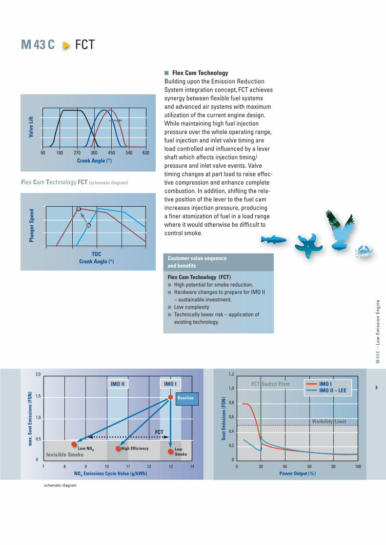
Customer value sequence and benefits
Flex Cam Technology (FCT)■ High potential for smoke reduction.■ Hardware changes to prepare for IMO II
– sustainable investment.■ Low complexity ■ Technically lower risk – application of
existing technology.
■ Flex Cam TechnologyBuilding upon the Emission ReductionSystem inte gration concept, FCT achievessynergy be tween flexible fuel systems and advanced air systems with maximum utilization of the current engine design.While maintaining high fuel injection pressure over the whole operating range,fuel injection and inlet valve timing are load controlled and influenced by a levershaft which affects injection timing/pressure and inlet valve events. Valvetiming changes at part load to raise effec-tive compression and enhance completecombustion. In addition, shifting the rela-tive position of the lever to the fuel camincreases injection pressure, pro ducing a finer atomization of fuel in a load rangewhere it would otherwise be difficult tocontrol smoke.
Flex Cam Technology FCT (schematic diagram)
Valv
e Li
ftPl
unge
r Spe
ed
Crank Angle (°)
TDCCrank Angle (°)
90 180 270 360 450 540 630
M 43 C FCTm
ax. S
oot E
mis
sion
s (F
SN)
7 8 9 10 11 12 130
0,5
1,0
2,0
14
NOx Emissions Cycle Value (g/kWh)
1,5
IMO IIMO II
FCT
Baseline
schematic diagram
Low Smoke
Low NOx High Efficiency
Soot
Em
issi
ons
(FSN
)
Power Output (%)
Invisible Smoke
1,2
1,0
0,8
0,6
0,4
0,2
00 20 40 60 80 100
Visibility Limit
IMO IIMO II – LEE
FCT Switch Point
M_43_C_FCT_12_2009.qxd:Layout 1 05.02.2010 10:36 Uhr Seite 3
4
M_43_C_FCT_12_2009.qxd:Layout 1 05.02.2010 10:36 Uhr Seite 4

5
M43
C –
Low
Em
issi
on E
ngin
e
Swept volume: 88.6 l /cyl.Output/cyl.: 1000 kWBMEP: 27.1 barRevolutions: 500/514 rpmTurbocharging: single logDirection of rotation: clockwise, option: counter-clockwise
Engine centre distance: 3,400 mm
Removal of cylinder liner:in transverse direction 4165 mmin longitudinal direction 4610 mm
Nozzle position: ask for availability
This engine is only available with dry oil sump
Engine with turbocharger at free end available, ask for dimensions
M 43 C – Low Emission Engine Engine Description (Preliminary)
Engine A B C D E G H t6 M 43 C 1396 8251 1583 1255 2878 750 4194 93.0 7 M 43 C 1396 9068 1583 1255 2878 750 4749 106.0 8 M 43 C 1396 9798 1583 1255 2878 750 4749 114.09 M 43 C 1396 10528 1583 1255 2878 750 4749 126.0
Spec. fuelconsumption
Outp
ut
rang
e
Engine
Spee
d
Mea
n ef
f.pr
essu
re
Mea
n pi
ston
spee
d
Bore
Stro
ke
6 M 43 C
7 M 43 C
8 M 43 C
9 M 43 C
85%100%
kW
60006000700070008000800090009000
mhp
8160816095209520
10880108801224012240
rpm
500514500514500514500514
m/s
10.210.510.210.510.210.510.210.5
mm
430430430430430430430430
g/kWh
177177177177177177177177
bar
27.126.427.126.427.126.427.126.4
mm
610610610610610610610610
g/kWh
177177177177177177177177
Dimensions (mm) and Weights ( t )
M_43_C_FCT_12_2009.qxd:Layout 1 05.02.2010 10:36 Uhr Seite 5

6
Cylinder 6 7 8 9
Performance data
Maximum continous rating acc. ISO 3046/1 kW 6000 7000 8000 9000Speed 1/min 500/514 500/514 500/514 500/514Minimum speed 1/min 300 300 300 300Brake mean effective pressure bar 27.1 27.1 27.1 27.1Charge air pressure bar 4 4 4 4Firing pressure bar 210 210 210 210Combustion air demand (ta = 20 °C) m3/h 35000 40850 46700 52250Specific fuel oil consumptionn = const 1) 100 % g/kWh 177 177 177 177
85 % g/kWh 177 177 177 17775 % g/kWh -/179 -/179 -/179 -/17950 % g/kWh -/185 -/185 -/185 -/185
Lubricating oil consumption 2) g/kWh 0.6 0.6 0.6 0.6NOX emission 3) g/kWh 10 10 10 10Turbocharger type ABB TPL 71-C ABB TPL 76-C ABB TPL 76-C ABB TPL 76-C
Fuel
Engine driven booster pump m3/h -/- -/- -/- -/-Stand-by booster pump m3/h 4.2/10 4.9/10 5.6/10 6.3/10Mesh size MDO fine filter mm 0.025 0.025 0.025 0.025Mesh size HFO automatic filter mm 0.010 0.010 0.010 0.010Mesh size HFO fine filter mm 0.034 0.034 0.034 0.034Nozzle cooling by lubricating oil system
Lubricating Oil
Engine driven pump m3/h/bar 146/10 146/10 203/10 203/10Independent pump m3/h/bar 120/10 140/10 160/10 180/10Working pressure on engine inlet bar 4 - 5 4 - 5 4 - 5 4 - 5Engine driven suction pump m3/h/bar -/- -/- -/- -/-Independent suction pump m3/h/bar 175/3 175/3 240/3 240/3Priming pump pressure/suck pump m3/h/bar 16/5 16/5 20/5 20/5Sump tank content/dry sump content m3 8.4 9.8 11.2 12.6Temperature at engine inlet °C 60 - 65 60 - 65 60 - 65 60 - 65Temperature controller NB mm 125 125 150 150Double filter NB mm 150 150 150 150Mesh size double filter mm 0.08 0.08 0.08 0.08Mesh size automatic filter mm 0.03 0.03 0.03 0.03
M 43 C – Low Emission Engine Technical Data (Preliminary)
M_43_C_FCT_12_2009.qxd:Layout 1 05.02.2010 10:36 Uhr Seite 6

7
M43
C –
Low
Em
issi
on E
ngin
e
Cylinder 6 7 8 9
Fresh water cooling
Engine content m3 0.6 0.7 0.8 0.9Pressure at engine inlet min/max bar 2.5/6.0 2.5/6.0 2.5/6.0 2.5/6.0Header tank capacity m3 0.6 0.6 0.6 0.6Temperature at engine outlet °C 80 - 90 80 - 90 80 - 90 80 - 90
Two circuit system
Engine driven pump HT m3/h/bar -/- -/- -/- -/-Independent pump HT m3/h/bar 100/4.5 110/4.6 120/4.6 130/4.5HT-Controller NB mm 125 125 150 150Water demand LT-charge air cooler m3/h 80 100 100 100Temperature at LT-charge air cooler inlet °C 38 38 38 38
Heat Dissipation
Specific jacket water heat kJ/kW 500 500 500 500Specific lub oil heat kJ/kW 490 490 490 490Lub oil cooler kW 820 960 1090 1225Jacket water kW 835 975 1115 1250Charge air cooler (HT-Stage) 4) kW 2436 2811 3213 3564Charge air cooler (LT-Stage) 4) kW 470 570 648 772(HT-Stage before engine)Heat radiation engine kW 260 300 330 390
Exhaust
Silencer/spark arrester NB mm 900 1000 1000 1000Pipe diameter NB after turbine mm 900 1000 1000 1000Exhaust gas temperature after turbine (intake air 25°C) 5) °C 300 305 305 310Exhaust gas mass flow (intake air 25 °C) 5) kg/h 43260 50490 57720 64580Maximum exhaust gas pressure drop bar 0.03 0.03 0.03 0.03
Starting air
Starting air pressure max. bar 30 30 30 30Minimum starting air pressure bar 14 14 14 14Air consumption per start 6) Nm3 2.4 2.4 3 3
1 ) Reference conditions: LCV = 42700 kJ/kg, ambient temperature 25 °C charge air coolant temperature 25 °C, tolerance 5 %, + 1 % for engine driven pump
2 ) Standard value based on rated output, tolerance ± 0.3 g/kWh3 ) MARPOL 73/78, annex VI, cycle E2, D24 ) Charge air heat based on 45 °C ambient temperature5 ) Tolerance 10 %, rel. humidity 60 %6 ) Preheated engine
M_43_C_FCT_12_2009.qxd:Layout 1 05.02.2010 10:36 Uhr Seite 7
8
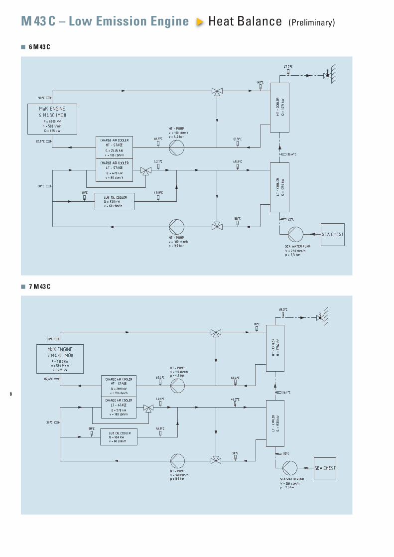
■ 6 M 43 C
■ 7 M 43 C
M 43 C – Low Emission Engine Heat Balance (Preliminary)
M_43_C_FCT_12_2009.qxd:Layout 1 05.02.2010 10:36 Uhr Seite 8
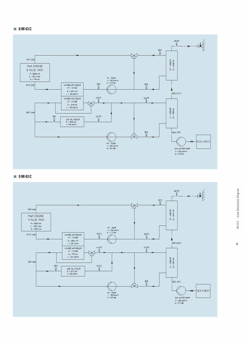
■ 8 M 43 C
■ 9 M 43 C
9
M43
C –
Low
Em
issi
on E
ngin
e
M_43_C_FCT_12_2009.qxd:Layout 1 05.02.2010 10:36 Uhr Seite 9

M a i n P r o p u l s i o n E n g i n e s
10
■ Medium-Speed Engines
One Strong Line of World-Class Diesel Engines Perfect Solutions for Main Propulsion and On-Board Power Supply
Caterpillar Marine Power SystemsSales and Service Organization
The Program: Quality is our MottoFor more than 80 years we have devel-oped, built, supplied and serviced dieselengines – worldwide. Today CaterpillarMarine with its brands Cat and MaK offer high-speed and medium-speed engines with power ratings from 11 kW to 16,000 kW. Many different engine families are available to meet your specific application needs.
Cat and MaK diesel engines are distin-guished by high reliability, extremely lowoperational costs, simple installation andmaintenance and compliance with IMOenvironmental regulations.
Caterpillar has combined the sales andservice activities and responsibility oftheir Cat and MaK brand marine enginebusiness into Caterpillar Marine Power Systems with headquarters in Hamburg/Germany.
In setting-up this worldwide structure, we have concentrated on integrating theCat and MaK brand groups into a single,united marine team, which utilises the particular expertise of each group.
Commercial marine engine business is split into three geographic regions, – Europe, Africa, Middle East– Americas– Asia-Pacific,
The application of engines in main andauxiliary marine power systems variesgreatly and extends from high-speedboats and yachts, through tugs, trawlersand offshore vessels to freighters, ferriesand cruise liners.
● M 32 C6, 8, 9 cylinder2,880 – 4,500 kW
● VM 32 C12, 16 cylinder5,760 – 8,000 kW
● M 25 C6, 8, 9 cylinder1,800 –3,000 kW
● M 20 C6, 8, 9 cylinder1,020–1,710 kW
M_43_C_FCT_12_2009.qxd:Layout 1 05.02.2010 10:36 Uhr Seite 10

11
M43
C –
Low
Em
issi
on E
ngin
e
MaK LEE will soon be part of all MaK engines!
Caterpillar Marine Power SystemsProduction Facilities
which manage all sales and product sup-port activities. They have direct responsi-bility for achieving the ambitious growthtargets set for the Cat and MaK brandsand for providing our customers anddealers with complete marine solutions.
Caterpillar ’s global dealer network pro -vid es a key competitive edge – customersdeal with people they know and trust.
Cat dealers strive to form a strong work - ing relationship with their customers, offering comprehensive and competentadvice from project support to repairwork.
Some of the most advanced manufactur-ing concepts are used at Caterpillar loca-tions throughout the world to produceengines in which reliability, economy andperformance are second-to-none.
From the production of core componentsto the assembly of complete engines,quality is always the top priority.
Comprehensive, recognized analysis systems, test procedures and measuringmethods ensure that quality requirementsare met throughout all the individual manufacturing phases. All of our produc-tion facilities are certified under 1:2000ISO 9001 EN, the international benchmarkthat is helping to set new quality stan-dards worldwide.
In addition to product quality, our cus-tomers expect comprehensive servicewhich in cludes the supply of spare partsthroughout the life of the engine.
Caterpillar Logistics Services, Inc., located in Morton, Illinois, is the largestparts distribution facility within the CatLogistics network and is also the head-quarters for all the worldwide distributioncentres. Morton utilises sophisticatedmaterial handling, storage and retrievalsystems to support Caterpillar’s customerservice goals.
● M 43 C6, 7, 8, 9 cylinder5,400 – 9,000 kW
● VM 43 C12, 16 cylinder10,800 –16,000 kW
M_43_C_FCT_12_2009.qxd:Layout 1 05.02.2010 10:37 Uhr Seite 11
Subject to change without notice.Leaflet No. 248 · 02.10 · e · L+S · VM3
© 2010 Caterpillar All Rights Reserved. Printed in Germany. CAT, CATERPILLAR, theirrespective logos, ACERT, ADEM, „Caterpillar Yellow“ and the POWER EDGE tradedress, as well as corporate identity used herein, are trademarks of Caterpillar andmay not be used without permission
Caterpillar Marine Power Systems is committed to sustainability. This document is printed on PEFC certificated paper.
Europe, Africa, Middle East
Caterpillar MarinePower SystemsNeumühlen 922763 Hamburg/Germany
Phone: +49 40 2380-3000Telefax: +49 40 2380-3535
Caterpillar Marine Asia Pacific Pte Ltd14 Tractor RoadSingapore 627973/SingaporePhone: +65 68287-600Telefax: +65 68287-624
Americas
MaK Americas Inc.
3450 Executive WayMiramar Park of CommerceMiramar, FL. 33025/USAPhone: +1 954 885 3200Telefax: +1 954 885 3131
Caterpillar Marine Trading(Shanghai) Co., Ltd.25/F, Caterpillar Marine Center1319, Yan’an West Road200050 Shanghai/P. R.ChinaPhone: +86 21 6226 2200Telefax: +86 21 6226 4500
Asia PacificHeadquarters
Caterpillar MarinePower SystemsNeumühlen 922763 Hamburg/Germany
Phone: +49 40 2380-3000Telefax: +49 40 2380-3535
For more information please visit our website:MARINE.CAT.COM
Caterpillar Marine Power Systems
TM
M_43_C_FCT_12_2009.qxd:Layout 1 05.02.2010 10:37 Uhr Seite 12