
Lytro camera technology: theory, algorithms, perf ormance ...zyu/MCP2013/MCP2013lytro.pdf · Lytro...
10
Lytro camera technology: theory, algorithms, performance analysis Todor Georgiev a , Zhan Yu b , Andrew Lumsdaine c , Sergio Goma a a Qualcomm; b University of Delaware; c Indiana University ABSTRACT The Lytro camera is the first implementation of a plenoptic camera for the consumer market. We consider it a successful example of the miniaturization aided by the increase in computational power characterizing mobile computational photography. The plenoptic camera approach to radiance capture uses a microlens array as an imaging system focused on the focal plane of the main camera lens. This paper analyzes the performance of Lytro camera from a system level perspective, considering the Lytro camera as a black box, and uses our interpretation of Lytro image data saved by the camera. We present our findings based on our interpretation of Lytro camera file structure, image calibration and image rendering; in this context, artifacts and final image resolution are discussed. Keywords: Lytro, Computational Photography, Plenoptic Camera, Light Field Camera, Integral Photography, Digital Optics 1. INTRODUCTION The Lytro camera is the first plenoptic camera for the consumer market. As it represents an example of the miniaturization process and the increase in computational power characterizing mobile computational photography, it is a living proof of the power of computation available to solve mobile photography challenges. Moreover, it exemplifies the new trend in computational photography that we call “digital optics.” This paper is centered around the optical design of the Lytro camera that implements digital optics features - e.g. focusing after the fact. In this context, it uses the full resolution rendering approach to produce final images from the captured radiance in the focal plane of the main camera lens. This approach allows to make use of radiance capture with significantly higher spatial resolution, with the ultimate goal of rendering images at spatial resolutions that are comparable to that of a traditional camera. As in the case of a radiance capture, because the captured dataset is increased many times compared to a traditional camera, new problems arise – specifically the most referred to is the ‘resolution problem’. This is a consequence of the rich dataset acquired and manifests in many current implementations – Lytro camera included – as a final spatial rendered resolution much smaller than a traditional camera using the same number of pixels for capturing data. In this paper, the resolution problem is treated in the context of the two variants of plenoptic capture, referred to as 1.0 and 2.0. The additional factors that influence achieving high resolution are analyzed and the approach evidently used by the Lytro camera and application for solving it is discussed. Practical issues such as Lytro application file structure and image calibration, image rendering, artifacts and final image resolution are also discussed based on our interpretation of Lytro captured data. We present results and measurements confirming the approach used by Lytro camera. This also points to the fact that traditional measurements used to quantify captured image spatial resolution are ill suited when it comes to evaluate the spatial resolution rendered by a computational camera. We conclude by showing that the capabilities of mobile computational photography will likely leverage plenoptic (aka lightfield) camera capabilities in conjunction with powerful computing resources to create "digital optics." It is our belief that although it does not (yet) include a smart phone or other mobile computing device, the Lytro camera incorporates many of the technologies that are likely to be seen in the future as part of mobile cameras. Captured plenoptic data can be manipulated and transformed in purely digital form. Focusing can now be done with a “digital lens” – algorithmically rather than optically – bulky camera optics can be completely eliminated. The Lytro camera clearly demonstrates that optical camera settings such as focus and aperture can be applied computationally – after the original image has been captured – and in an infinite variety. The power and capabilities of mobile computational photography thus depends on the power and capabilities of computing devices – which portends an exciting future for these devices as they become smaller but at the same time more capable. Please verify that (1) all pages are present, (2) all figures are correct, (3) all fonts and special characters are correct, and (4) all text and figures fit within the red margin lines shown on this review document. Complete formatting information is available at http://SPIE.org/manuscripts Return to the Manage Active Submissions page at http://spie.org/app/submissions/tasks.aspx and approve or disapprove this submission. Your manuscript will not be published without this approval. Please contact [email protected] with any questions or concerns. 8667 - 70 V. 5 (p.1 of 10) / Color: No / Format: Letter / Date: 2/18/2013 9:51:21 PM SPIE USE: ____ DB Check, ____ Prod Check, Notes:
Transcript of Lytro camera technology: theory, algorithms, perf ormance ...zyu/MCP2013/MCP2013lytro.pdf · Lytro...
Lytro camera technology: theory, algorithms, performance analysis
Todor Georgieva, Zhan Yub, Andrew Lumsdainec, Sergio Gomaa aQualcomm; bUniversity of Delaware; cIndiana University
ABSTRACT
The Lytro camera is the first implementation of a plenoptic camera for the consumer market. We consider it a successful example of the miniaturization aided by the increase in computational power characterizing mobile computational photography. The plenoptic camera approach to radiance capture uses a microlens array as an imaging system focused on the focal plane of the main camera lens. This paper analyzes the performance of Lytro camera from a system level perspective, considering the Lytro camera as a black box, and uses our interpretation of Lytro image data saved by the camera. We present our findings based on our interpretation of Lytro camera file structure, image calibration and image rendering; in this context, artifacts and final image resolution are discussed. Keywords: Lytro, Computational Photography, Plenoptic Camera, Light Field Camera, Integral Photography, Digital Optics
1. INTRODUCTION The Lytro camera is the first plenoptic camera for the consumer market. As it represents an example of the miniaturization process and the increase in computational power characterizing mobile computational photography, it is a living proof of the power of computation available to solve mobile photography challenges. Moreover, it exemplifies the new trend in computational photography that we call “digital optics.” This paper is centered around the optical design of the Lytro camera that implements digital optics features - e.g. focusing after the fact. In this context, it uses the full resolution rendering approach to produce final images from the captured radiance in the focal plane of the main camera lens. This approach allows to make use of radiance capture with significantly higher spatial resolution, with the ultimate goal of rendering images at spatial resolutions that are comparable to that of a traditional camera. As in the case of a radiance capture, because the captured dataset is increased many times compared to a traditional camera, new problems arise – specifically the most referred to is the ‘resolution problem’. This is a consequence of the rich dataset acquired and manifests in many current implementations – Lytro camera included – as a final spatial rendered resolution much smaller than a traditional camera using the same number of pixels for capturing data. In this paper, the resolution problem is treated in the context of the two variants of plenoptic capture, referred to as 1.0 and 2.0. The additional factors that influence achieving high resolution are analyzed and the approach evidently used by the Lytro camera and application for solving it is discussed. Practical issues such as Lytro application file structure and image calibration, image rendering, artifacts and final image resolution are also discussed based on our interpretation of Lytro captured data. We present results and measurements confirming the approach used by Lytro camera. This also points to the fact that traditional measurements used to quantify captured image spatial resolution are ill suited when it comes to evaluate the spatial resolution rendered by a computational camera. We conclude by showing that the capabilities of mobile computational photography will likely leverage plenoptic (aka lightfield) camera capabilities in conjunction with powerful computing resources to create "digital optics." It is our belief that although it does not (yet) include a smart phone or other mobile computing device, the Lytro camera incorporates many of the technologies that are likely to be seen in the future as part of mobile cameras. Captured plenoptic data can be manipulated and transformed in purely digital form. Focusing can now be done with a “digital lens” – algorithmically rather than optically – bulky camera optics can be completely eliminated. The Lytro camera clearly demonstrates that optical camera settings such as focus and aperture can be applied computationally – after the original image has been captured – and in an infinite variety. The power and capabilities of mobile computational photography thus depends on the power and capabilities of computing devices – which portends an exciting future for these devices as they become smaller but at the same time more capable.
Please verify that (1) all pages are present, (2) all figures are correct, (3) all fonts and special characters are correct, and (4) all text and figures fit within the redmargin lines shown on this review document. Complete formatting information is available at http://SPIE.org/manuscripts
Return to the Manage Active Submissions page at http://spie.org/app/submissions/tasks.aspx and approve or disapprove this submission. Your manuscript willnot be published without this approval. Please contact [email protected] with any questions or concerns.
8667 - 70 V. 5 (p.1 of 10) / Color: No / Format: Letter / Date: 2/18/2013 9:51:21 PM
SPIE USE: ____ DB Check, ____ Prod Check, Notes:
2. TRADITIONAL CAMERA AND PLENOPTIC CAMERA
2.1 Traditional camera
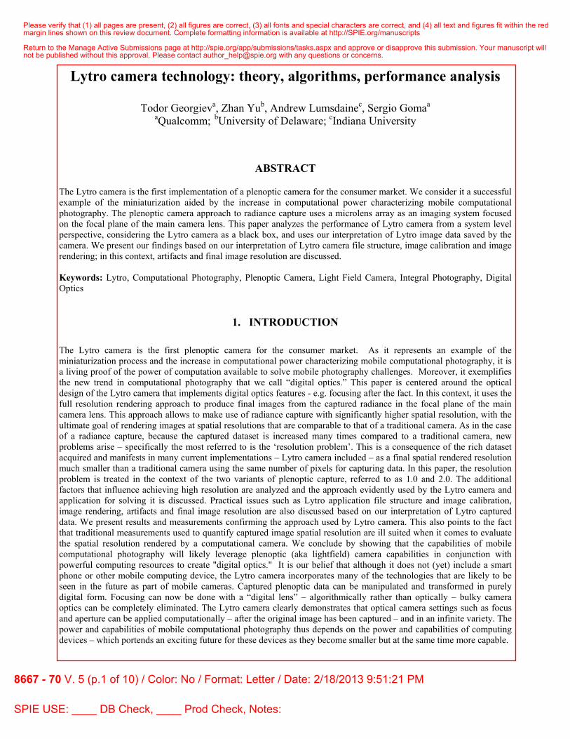
A traditional camera lens performs a projective transform to map the outside world into the inside world behind the lens. Conceptually, this mapping is done on a point level. The fundamental problem of the traditional camera that Lytro addresses is the following. If a sensor plane is placed somewhere to capture the 3D point cloud inside the camera, it can strictly speaking capture only points that are on top of the sensor plane. All points that are away from that plane are recorded as fuzzy spots – based on the pencils of rays coming from these points and intersecting the sensor. In other words, only one plane is captured sharp. Points away from the plane of focus appear blurry.
Figure 1. A traditional camera lens maps the outside world in front of the lens into the inside world behind the lens. The goal of radiance capture is that instead of projecting all on a single plane, we would map outside rays projectivly into the inside world, and then record the intensity of each ray.
The goal of integral photography as formulated by Lippmann1 back in 1908 is to capture all rays in 3D, and not just one plane of points. Conceptually at least this can be done by considering the projective transform of lines (physically represented by light rays) instead of the projective transform of points. Each 3D point is represented by the pencil of lines intersecting at that point. It is clear that if the intensities (radiance) of all those rays are captured instead of the intensity of the points, later 3D imaging, refocusing, and other effects could be implemented -- after the fact. Such camera would capture not just an image of the object, but a “fingerprint” of the whole set of light rays in the scene.
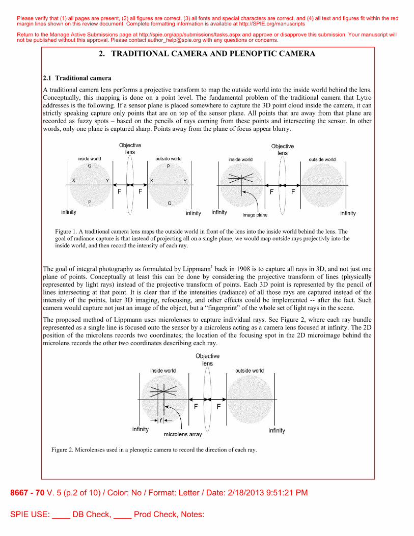
The proposed method of Lippmann uses microlenses to capture individual rays. See Figure 2, where each ray bundle represented as a single line is focused onto the sensor by a microlens acting as a camera lens focused at infinity. The 2D position of the microlens records two coordinates; the location of the focusing spot in the 2D microimage behind the microlens records the other two coordinates describing each ray.
Figure 2. Microlenses used in a plenoptic camera to record the direction of each ray.
Please verify that (1) all pages are present, (2) all figures are correct, (3) all fonts and special characters are correct, and (4) all text and figures fit within the redmargin lines shown on this review document. Complete formatting information is available at http://SPIE.org/manuscripts
Return to the Manage Active Submissions page at http://spie.org/app/submissions/tasks.aspx and approve or disapprove this submission. Your manuscript willnot be published without this approval. Please contact [email protected] with any questions or concerns.
8667 - 70 V. 5 (p.2 of 10) / Color: No / Format: Letter / Date: 2/18/2013 9:51:21 PM
SPIE USE: ____ DB Check, ____ Prod Check, Notes:
2.2 Plenoptic camera and current implementations (Lytro camera)
Considering the above approach, a plenoptic camera would essentially replace pixels with microlenses, and thus produce final image resolution equal to the number of the microlenses. The additional information available inside each microlenses is used for digital focusing after the fact and for other 3D effects. In the case of Lytro the number of microlenses is approximately 100,000 and a final image resolution of 0.1 megapixels could be expected. However the final image resolution that we have measured in Lytro is typically around 0.3 megapixels. How can this effect of improved resolution be explained?
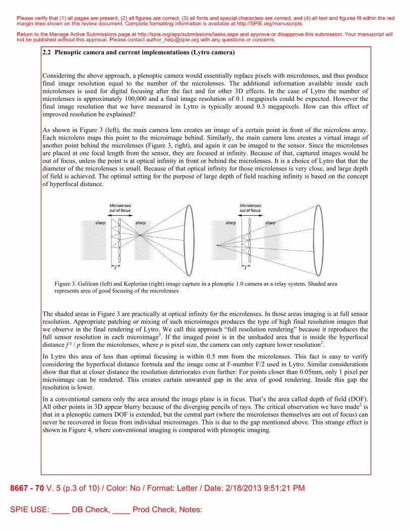
As shown in Figure 3 (left), the main camera lens creates an image of a certain point in front of the microlens array. Each microlens maps this point to the microimage behind. Similarly, the main camera lens creates a virtual image of another point behind the microlenses (Figure 3, right), and again it can be imaged to the sensor. Since the microlenses are placed at one focal length from the sensor, they are focused at infinity. Because of that, captured images would be out of focus, unless the point is at optical infinity in front or behind the microlenses. It is a choice of Lytro that that the diameter of the microlenses is small. Because of that optical infinity for those microlenses is very close, and large depth of field is achieved. The optimal setting for the purpose of large depth of field reaching infinity is based on the concept of hyperfocal distance.
Figure 3. Galilean (left) and Keplerian (right) image capture in a plenoptic 1.0 camera as a relay system. Shaded area represents area of good focusing of the microlenses
The shaded areas in Figure 3 are practically at optical infinity for the microlenses. In those areas imaging is at full sensor resolution. Appropriate patching or mixing of such microimages produces the type of high final resolution images that we observe in the final rendering of Lytro. We call this approach “full resolution rendering” because it reproduces the full sensor resolution in each microimage3. If the imaged point is in the unshaded area that is inside the hyperfocal distance f ² / p from the microlenses, where p is pixel size, the camera can only capture lower resolution2.
In Lytro this area of less than optimal focusing is within 0.5 mm from the microlenses. This fact is easy to verify considering the hyperfocal distance formula and the image cone at F-number F/2 used in Lytro. Similar considerations show that that at closer distance the resolution deteriorates even further: For points closer than 0.05mm, only 1 pixel per microimage can be rendered. This creates cartain unwanted gap in the area of good rendering. Inside this gap the resolution is lower.
In a conventional camera only the area around the image plane is in focus. That’s the area called depth of field (DOF). All other points in 3D appear blurry because of the diverging pencils of rays. The critical observation we have made2 is that in a plenoptic camera DOF is extended, but the central part (where the microlenses themselves are out of focus) can never be recovered in focus from individual microimages. This is due to the gap mentioned above. This strange effect is shown in Figure 4, where conventional imaging is compared with plenoptic imaging.
Please verify that (1) all pages are present, (2) all figures are correct, (3) all fonts and special characters are correct, and (4) all text and figures fit within the redmargin lines shown on this review document. Complete formatting information is available at http://SPIE.org/manuscripts
Return to the Manage Active Submissions page at http://spie.org/app/submissions/tasks.aspx and approve or disapprove this submission. Your manuscript willnot be published without this approval. Please contact [email protected] with any questions or concerns.
8667 - 70 V. 5 (p.3 of 10) / Color: No / Format: Letter / Date: 2/18/2013 9:51:21 PM
SPIE USE: ____ DB Check, ____ Prod Check, Notes:
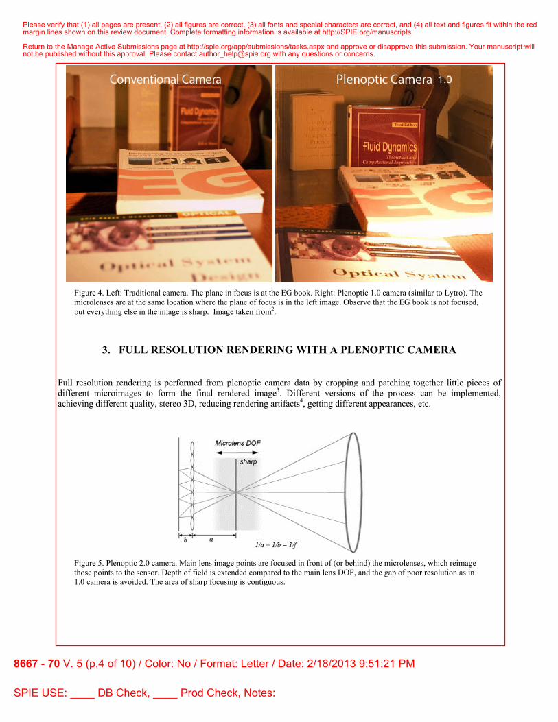
Figure 4. Left: Traditional camera. The plane in focus is at the EG book. Right: Plenoptic 1.0 camera (similar to Lytro). The microlenses are at the same location where the plane of focus is in the left image. Observe that the EG book is not focused, but everything else in the image is sharp. Image taken from2.
3. FULL RESOLUTION RENDERING WITH A PLENOPTIC CAMERA
Full resolution rendering is performed from plenoptic camera data by cropping and patching together little pieces of different microimages to form the final rendered image3. Different versions of the process can be implemented, achieving different quality, stereo 3D, reducing rendering artifacts4, getting different appearances, etc.
Figure 5. Plenoptic 2.0 camera. Main lens image points are focused in front of (or behind) the microlenses, which reimage those points to the sensor. Depth of field is extended compared to the main lens DOF, and the gap of poor resolution as in 1.0 camera is avoided. The area of sharp focusing is contiguous.
Please verify that (1) all pages are present, (2) all figures are correct, (3) all fonts and special characters are correct, and (4) all text and figures fit within the redmargin lines shown on this review document. Complete formatting information is available at http://SPIE.org/manuscripts
Return to the Manage Active Submissions page at http://spie.org/app/submissions/tasks.aspx and approve or disapprove this submission. Your manuscript willnot be published without this approval. Please contact [email protected] with any questions or concerns.
8667 - 70 V. 5 (p.4 of 10) / Color: No / Format: Letter / Date: 2/18/2013 9:51:21 PM
SPIE USE: ____ DB Check, ____ Prod Check, Notes:

One alternative design that can be considered3 is the “Focused plenoptic” or “Plenoptic 2.0” camera, in which the main lens is focused away from the microlenses (see Figure 5). In other words, the useful area in the 3D world that needs to be imaged is focused a distance a in front of the microlenses, and the microlenses are focused on that image by appropriately displacing them at carefully chosen distance b different from their focal length. In this way the depth of field is contiguous around the area of interest and there is no gap in the focusing as in the earlier “Plenoptic 1.0” design. This 2.0 approach is used commercially in the cameras of Raytrix5.
To summarize, full resolution rendering is possible in both 1.0 and 2.0 designs, and it produces quality images of resolution much better than 1 pixel per microlens. Plenoptic 1.0 camera has wider DOF, but suffers from a gap in resolution in the middle, while Plenoptic 2.0 has shallower but continuous DOF. Extensive experimentation and theoretical considerations have shown that typically final images are produced by full resolution rendering at 20X lower resolution than that of the sensor. Considering that typical microlens count is by a factor of 100X lower than the pixel count of the sensor, the gain in full resolution rendering is by a factor of 5. In a later section we will show that this is also the case with Lytro. Further superresolution methods can improve that.
4. LYTRO DATA REPOSITORY AND FILE FORMATS Processing and viewing pictures taken with the Lytro camera requires the use of the Lytro application. The Lytro application is currently for Mac OS X and for 64-bit Windows 7.
After the Lytro application is installed, an installed background process will recognize when a Lytro camera is connected and will start the Lytro application automatically. When the Lytro application runs with the camera connected, it will offer to import any new images on the camera. Before the transfer process, the Lytro camera will first check if the configuration data has been downloaded before by checking the serial number with the local data. If not, a one time configuration data downloading will be conducted before any further process. In the transfer process, the Lytro application will transfer raw lightfield images from the camera and then render a stack of images, each focused at a different depth. It will also combine these into a “living image” which is a flash application enabling interactive selection of different images in the stack, based on where a user clicks in the “active image.”
4.1 File Structure
On Mac OS X, the The Lytro application keeps its data in the user subdirectory Pictures/Lytro.lytrolib. On Windows, the Lytro application keeps its data in the user subdirectory AppData/Local/Lytro. For both Mac OS X and Windows, there are three subdirectories and two files at the top level:
• cameras/ – subdirectory containing backup configuration data for each camera connected to the Lytro application. The data for each camera is kept in a subdirectory named sn-AXXXXXXXXX, where each X represents and the numbering reflects the serial number of each camera.
• images/ – subdirectory containing image data for the Lytro application. Both the original lightfields and the focal stacks are kept.
• thumbs/ – subdirectory containing thumbnails of the processed image stacks. • library.db – SQLite database containing selected meta information about the images in the image subdirectory • library.bkp – backup copy of the SQLite database.
The Lytro application stores four main sets of data in its data store (which files are organized by sqlite.db):
• Camera calibration data / modulation images. These are stored within the data.C containers in the cameras subdirectory.
• Raw lightfield files. These files are stored as images/NN/IMG_NNNN.lfp (where each N is a digit). The raw lightfield files store the raw image data (not demosaiced) in 12-bit compressed format along with meta-information about the shot (stored as a header in JSON format).
• Processed lightfield files (focal stacks) are computed locally and stored as images/NN/IMG_NNNN-stk.lfp. The
Please verify that (1) all pages are present, (2) all figures are correct, (3) all fonts and special characters are correct, and (4) all text and figures fit within the redmargin lines shown on this review document. Complete formatting information is available at http://SPIE.org/manuscripts
Return to the Manage Active Submissions page at http://spie.org/app/submissions/tasks.aspx and approve or disapprove this submission. Your manuscript willnot be published without this approval. Please contact [email protected] with any questions or concerns.
8667 - 70 V. 5 (p.5 of 10) / Color: No / Format: Letter / Date: 2/18/2013 9:51:21 PM
SPIE USE: ____ DB Check, ____ Prod Check, Notes:
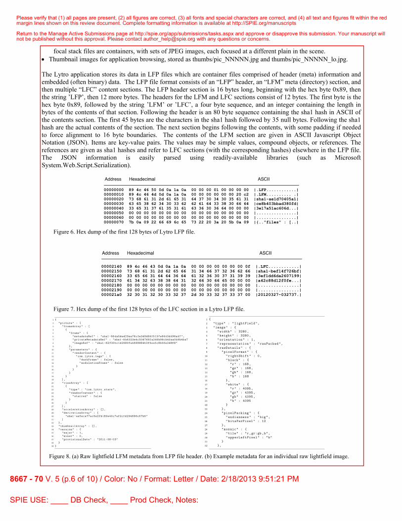
focal stack files are containers, with sets of JPEG images, each focused at a different plain in the scene. • Thumbnail images for application browsing, stored as thumbs/pic_NNNNN.jpg and thumbs/pic_NNNNN_lo.jpg.
The Lytro application stores its data in LFP files which are container files comprised of header (meta) information and embedded (often binary) data. The LFP file format consists of an “LFP” header, an “LFM” meta (directory) section, and then multiple “LFC” content sections. The LFP header section is 16 bytes long, beginning with the hex byte 0x89, then the string ’LFP’, then 12 more bytes. The headers for the LFM and LFC sections consist of 12 bytes. The first byte is the hex byte 0x89, followed by the string ’LFM’ or ’LFC’, a four byte sequence, and an integer containing the length in bytes of the contents of that section. Following the header is an 80 byte sequence containing the sha1 hash in ASCII of the contents section. The first 45 bytes are the characters in the sha1 hash followed by 35 null bytes. Following the sha1 hash are the actual contents of the section. The next section begins following the contents, with some padding if needed to force alignment to 16 byte boundaries. The contents of the LFM section are given in ASCII Javascript Object Notation (JSON). Items are key-value pairs. The values may be simple values, compound objects, or references. The references are given as sha1 hashes and refer to LFC sections (with the corresponding hashes) elsewhere in the LFP file. The JSON information is easily parsed using readily-available libraries (such as Microsoft System.Web.Script.Serialization).
Figure 6. Hex dump of the first 128 bytes of Lytro LFP file.
Figure 7. Hex dump of the first 128 bytes of the LFC section in a Lytro LFP file.
Figure 8. (a) Raw lightfield LFM metadata from LFP file header. (b) Example metadata for an individual raw lightfield image.
Please verify that (1) all pages are present, (2) all figures are correct, (3) all fonts and special characters are correct, and (4) all text and figures fit within the redmargin lines shown on this review document. Complete formatting information is available at http://SPIE.org/manuscripts
Return to the Manage Active Submissions page at http://spie.org/app/submissions/tasks.aspx and approve or disapprove this submission. Your manuscript willnot be published without this approval. Please contact [email protected] with any questions or concerns.
8667 - 70 V. 5 (p.6 of 10) / Color: No / Format: Letter / Date: 2/18/2013 9:51:21 PM
SPIE USE: ____ DB Check, ____ Prod Check, Notes:

4.2 Image Files
There are two types of Lytro image files – raw lightfield images and focal stack images. Both have the .lfp extension but the focal stack image files also end with -stk.lfp.
4.3 Raw Lightfield Image Files
The raw lightfield LFM portion has three top level sections: picture, thumbnailArray, and version. The picture section has four sub-sections: frameArray, viewArray, accelerationArray, and derivationArray. The frame section has three sub-sections (which are each references): metadataRef, privateMetadataRef, and imageRef. In the raw lightfield image file, the accelerationArray section is empty.
The section referred to by metadataRef contains a significant amount of information about the state of the camera when the image was captured, including fixed parameters such as pixel pitch, microlens pitch, and so forth, as well as adjustable parameters focal distance, zoom, and shutter speed.
The privateMetadataRef section contains the serial numbers of the camera sensor and of the camera itself.
The section referred to by imageRef contains the actual raw image data from the camera. The data is an array of bytes. The pixel data are stored in a compressed format with 12 bits per pixel.
4.4 Focused Image Stack Files
The focused image stack LFM portion has three top level sections: picture, thumbnailArray, and version. The picture section has four sub-sections: frameArray, viewArray, accelerationArray, and derivationArray. The frame section has three sub-sections (which are each references): metadataRef, privateMetadataRef, and imageRef. These latter three references are recapitulated from the corresponding lightfield image file (i.e., have the same sha1 values) but the actual data are not contained in the file.
In the focused image stack file, the accelerationArray contains information about the focal stack (hence the name “acceleration array”).
The accelerationArray contains three sub-sections: type, generator, and vendorContent. The vendorContent section has five sub-sections: viewParameters, displayParameters, defaultLambda, depthLUT, and imageArray. The depthLUT section contains dimensions of the depth look up table and a reference to its contents. The imageArray section contains information about each image in the focal stack: representation, width, height, lambda, and a reference to the image data.
4.5 Camera Files
In the individual camera subdirectory (Pictures/Lytro.lytrolib/camers/sn-A*) are four binary files: data.C.0, data.C.1, data.C.2, and data.C.3. The headers of these files indicate they are “LFP” files and they conform to the format described above. In the specific case of the camera files (data.C.[0123]), each entry consists of a file name and a reference to the file contents. The file names in the camera file LFM section are given in DOS format.
Of particular note are files named “mod_00MM.raw” and “mod_00NN.raw” which are pairs of calibration images. The camera parameters when taking these images are given in the corresponding “mod_00MM.txt” and “mod_00NN.txt” files. The number of the mod files runs from 0000 to 00061 (there are 62 images or 31 pairs). Further information can be found from sources on the web, such as the following: Github8, Marcansoft9, and LightField Forum10.
Please verify that (1) all pages are present, (2) all figures are correct, (3) all fonts and special characters are correct, and (4) all text and figures fit within the redmargin lines shown on this review document. Complete formatting information is available at http://SPIE.org/manuscripts
Return to the Manage Active Submissions page at http://spie.org/app/submissions/tasks.aspx and approve or disapprove this submission. Your manuscript willnot be published without this approval. Please contact [email protected] with any questions or concerns.
8667 - 70 V. 5 (p.7 of 10) / Color: No / Format: Letter / Date: 2/18/2013 9:51:21 PM
SPIE USE: ____ DB Check, ____ Prod Check, Notes:

5. RAW IMAGES AND CALIBRATION The RAW microimages show vignetting, noise, random shift of microlenses, etc. To correct for these, a calibration step is required as imperfections are camera specific. The Lytro implementation is very good at that. It’s actually hard to achieve rendering as clean and with as low noise and as good color as achieved by Lytro rendering.
We believe that for the purpose of calibrating and correcting the raw captured data, modulation images are included with each Lytro camera. These images would be captured at the time of camera manufacturing. Stored, are 62 12bit raw images, each with a time stamp and full metadata. According to those files time stamp, acquiring the images takes about 30 minutes. Out of those, two images are dark and at different exposures suggesting that can be used to eliminate hot pixels.
Modulation images are captured at different main lens parameters, like focus and zoom, so each new picture can be calibrated based on the closest modulation images according to its parameters. One possible workflow is:
(1) Divide the captured image by the corresponding modulation image (anti-vignetting) at similar parameters. Clean up pattern noise, dark noise.
(2) Compute the true microimage centers based on modulation images. Use computed centers for rendering. In our opinion, this is the most important calibration step.
(3) Possibly, Lytro is using a lens model of the main camera lens to compute centers. We believe that without careful consideration of centers, quality rendering cannot be achieved.
Demosaicing can be done before rendering, directly on the raw image, or during rendering -- without significant difference in quality between the two approaches.
Lytro acquired data does not respond well to our superresolution or superdemosaicing algorithms, which is an indication of the fact that microlenses MTF is approximately matching the MTF of the sensor. In this context, we believe Lytro performs a well-balanced imaging according to the Nyquist criteria.
6. FINAL IMAGE RESOLUTION
We have taken pictures of resolution charts placed at different depths from the camera and measured the MTF of the final rendered image such that best focusing after the fact is achieved on the resolution chart. Our goal was to verify the original hypothesis that Lytro is a plenoptic 1.0 camera showing a resolution gap. Our pictures were taken with no zoom. Figures 9 and 10 show two of the rendered images, captured at 15 and 20 cm depth respectively. These are resolution chart images, each rendered by Lytro focused on the chart. Also, their computed MTFs are shown on the left.
Figure 9. Left: MTF at 15 cm from the camera, Right: Picture of the resolution chart rendered by Lytro that was used for computing the MTF.
Please verify that (1) all pages are present, (2) all figures are correct, (3) all fonts and special characters are correct, and (4) all text and figures fit within the redmargin lines shown on this review document. Complete formatting information is available at http://SPIE.org/manuscripts
Return to the Manage Active Submissions page at http://spie.org/app/submissions/tasks.aspx and approve or disapprove this submission. Your manuscript willnot be published without this approval. Please contact [email protected] with any questions or concerns.
8667 - 70 V. 5 (p.8 of 10) / Color: No / Format: Letter / Date: 2/18/2013 9:51:21 PM
SPIE USE: ____ DB Check, ____ Prod Check, Notes:
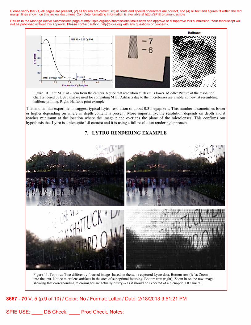
Figure 10. Left: MTF at 20 cm from the camera. Notice that resolution at 20 cm is lower. Middle: Picture of the resolution chart rendered by Lytro that we used for computing MTF. Artifacts due to the microlenses are visible, somewhat resembling halftone printing. Right: Halftone print example.
This and similar experiments suggest typical Lytro resolution of about 0.3 megapixels. This number is sometimes lower or higher depending on where in depth content is present. More importantly, the resolution depends on depth and it reaches minimum at the location where the image plane overlaps the plane of the microlenses. This confirms our hypothesis that Lytro is a plenoptic 1.0 camera and it is using a full resolution rendering approach.
7. LYTRO RENDERING EXAMPLE
Figure 11. Top row: Two differently focused images based on the same captured Lytro data. Bottom row (left): Zoom in into the text. Notice microlens artifacts in the area of suboptimal focusing. Bottom row (right): Zoom in on the raw image showing that corresponding microimages are actually blurry -- as it should be expected of a plenoptic 1.0 camera.
Please verify that (1) all pages are present, (2) all figures are correct, (3) all fonts and special characters are correct, and (4) all text and figures fit within the redmargin lines shown on this review document. Complete formatting information is available at http://SPIE.org/manuscripts
Return to the Manage Active Submissions page at http://spie.org/app/submissions/tasks.aspx and approve or disapprove this submission. Your manuscript willnot be published without this approval. Please contact [email protected] with any questions or concerns.
8667 - 70 V. 5 (p.9 of 10) / Color: No / Format: Letter / Date: 2/18/2013 9:51:21 PM
SPIE USE: ____ DB Check, ____ Prod Check, Notes:
8. CONCLUSION Many of the approaches of mobile computational photography will likely leverage plenoptic camera capabilities in conjunction with powerful computing resources to create "digital optics." Although the Lytro camera does not (yet) include a smart phone or other mobile computing device, it incorporates many of the technologies that we are likely to see in the future as part of mobile cameras, most notably a microlens array for capturing integral/plenoptic image data (the radiance). Captured plenoptic data can be manipulated and transformed in purely digital form. Focusing can now be done with what can be called digital optics – physical analog to how traditional bulky optics may be completely eliminated in the future. The Lytro camera clearly demonstrates that optical camera settings such as focus and aperture can be applied computationally – purely in digital form. The power and capabilities of mobile computational photography now depend on the power and capabilities of computing devices – an exciting future is in store for users of mobile computational cameras.
REFERENCES
[1] Lippmann, G., “Epreuves Reversibles. Photographies Integrales.” Academie des sciences, 446-451 (March
1908). [2] Georgiev, T., Lumsdaine, A., “Depth of Field in Plenoptic Cameras,” Eurographics 2009. [3] Lumsdaine, A., Georgiev, T., “The Focused Plenoptic Camera”, ICCP 2009. [4] Georgiev, T., Lumsdaine, A., “Reducing Plenoptic Camera Artifacts,” Computer Graphics Forum, June 2010. [5] Raytrix, http://www.raytrix.de/ [6] Ng, R., “Digital Light Field Photography”, Doctoral Dissertation, 2005. [7] Ng, R., Levoy, M., Brdif, M., Duval, G., Horowitz, M., Hanrahan, P., “Light Field Photography with a Hand-
held Plenoptic Camera”, Stanford University Computer Science Tech Report, February 2005. [8] Github, https://github.com/ [9] Marcansoft, http://marcansoft.com/blog/ [10] LightField Forum, http://lightfield-forum.com/en/
Please verify that (1) all pages are present, (2) all figures are correct, (3) all fonts and special characters are correct, and (4) all text and figures fit within the redmargin lines shown on this review document. Complete formatting information is available at http://SPIE.org/manuscripts
Return to the Manage Active Submissions page at http://spie.org/app/submissions/tasks.aspx and approve or disapprove this submission. Your manuscript willnot be published without this approval. Please contact [email protected] with any questions or concerns.
8667 - 70 V. 5 (p.10 of 10) / Color: No / Format: Letter / Date: 2/18/2013 9:51:21 PM
SPIE USE: ____ DB Check, ____ Prod Check, Notes: