LV1T 2009 Gesamtbuch EN.book Seite 1 Donnerstag, 26 ... · (see also IEC 60364-4-41, -5-52 and -6)....
16
11 Siemens LV 1 T · 2009 11 11/2 Introduction 4AV Non-Stabilized Power Supplies Filtered for Supply of Electronic Controls General data 11/3 - Overview 11/3 - Design 11/3 - Function 11/4 - Technical specifications 4AV2, 4AV4 power supplies, filtered, single-phase 11/6 - Overview 11/6 - Schematics 4AV3, 4AV5 power supplies, filtered, three-phase 11/7 - Overview 11/7 - Schematics Unfiltered for Supply of General Loads 4AV98 power supplies, unfiltered, single-phase 11/8 - Overview 11/8 - Design 11/8 - Schematics 4AV96 power supplies, unfiltered, three-phase 11/9 - Overview 11/9 - Design 11/9 - Technical specifications 11/9 - Schematics Project Planning Aids 11/10 - Dimensional drawings 6EP Stabilized Power Supplies 1) SITOP 6EP power supplies 1) See Catalog KT 10.1 "SITOP Power Supplies and LOGO!Power". Power Supplies © Siemens AG 2009
Transcript of LV1T 2009 Gesamtbuch EN.book Seite 1 Donnerstag, 26 ... · (see also IEC 60364-4-41, -5-52 and -6)....

11
Siemens LV 1 T · 2009
11
11/2 Introduction
4AV Non-Stabilized Power SuppliesFiltered for Supply of Electronic ControlsGeneral data
11/3 - Overview11/3 - Design11/3 - Function11/4 - Technical specifications
4AV2, 4AV4 power supplies, filtered, single-phase
11/6 - Overview11/6 - Schematics
4AV3, 4AV5 power supplies, filtered, three-phase
11/7 - Overview11/7 - Schematics
Unfiltered for Supply of General Loads4AV98 power supplies, unfiltered, single-phase
11/8 - Overview11/8 - Design11/8 - Schematics
4AV96 power supplies, unfiltered, three-phase
11/9 - Overview11/9 - Design11/9 - Technical specifications11/9 - Schematics
Project Planning Aids11/10 - Dimensional drawings
6EP Stabilized Power Supplies1) SITOP 6EP power supplies
1) See Catalog KT 10.1 "SITOP Power Supplies and LOGO!Power".
Power Supplies
LV1T_2009_Gesamtbuch_EN.book Seite 1 Donnerstag, 26. Februar 2009 2:00 14
© Siemens AG 2009

Power Supplies
Introduction
11/2 Siemens LV 1 T · 2009
11
■ Overview
4AV non-stabilized power supplies
6EP stabilized power supplies1)
Further products for power supplies can be found in Catalog KT 10.1 or on the Internet at http://www.siemens.com/sirius-supplying and http://www.siemens.com/sitop.
1) For more information see Catalog KT 10.1 "SITOP Power Supplies and LOGO!Power".
4AV21/23 4AV20/22/24/26 4AV4 4AV3 4AV5Filtered for supply of electronic controlsRipple < 5 % < 5 % < 5 % < 5 % < 5 %
Phase 1 1 1 3 3
Rated input voltage V AC 115 ... 415 115 ... 415 230 ... 415 200 ... 600 400 ... 415
Rated output voltage acc. to EN 61131-2 suitable for SIMATIC systems
V DC 24 24 24 24 24
Rated output current A 1 ... 4.2 2.5 ... 18 1.5 ... 10 15 ... 180 25, 35
Connection Screw terminals/flat connectors
Screw terminals/flat connectors or Cage Clamp terminals
Screw terminals/flat connectors or Cage Clamp terminals
Screw terminals/flat connectors
Screw terminals/flat connectors
Mounting Standard rail mounting
Screw and/or standard rail mounting
Screw and/or standard rail mounting
Screw mounting Screw mounting
CUUS approval at 60 °C Yes Yes No Partially No
4AV98 4AV96Unfiltered for supply of general loadsRipple 48.3 % < 5 %
Phase 1 3
Rated input voltage V AC 230 or 400 400
Rated output voltage V DC 24 30-27-24
Rated output current/rated power 50 ... 500 W
4 ... 25 A
Connection Screw terminals/flat connectors
Screw terminals/flat connectors
Mounting Screw mounting Screw mounting
CUUS approval No No
6EP11) LOGO!Power
6EP11) SITOP smart
6EP11) SITOP modular
6EP11) SITOP uninterruptible
Phase 1 1, 3 1, 2, 3 1
Rated input voltage V 100 ... 240 AC 48 ... 220 DC, 120 ... 230 AC, 120/230 AC,3 AC 400 ... 500
120/230 ... 500 AC, 120/230 AC, 3 AC 400 ... 500
24 DC
Rated output voltage V DC 5, 12, 15, 24 24, 48, 3 ... 52 24 24
Rated output current A 1.3 ... 6.3 0.375 ... 10 5 ... 40 6, 15, 40
Connection Screw terminals Screw terminals Screw terminals Screw terminals
Mounting Standard rail mounting
Standard rail mounting
Standard rail mounting
Standard rail mounting
Approval u, Cu u, Cu u, Cu u, Cu
LV1T_2009_Gesamtbuch_EN.book Seite 2 Donnerstag, 26. Februar 2009 2:00 14
© Siemens AG 2009

4AV Non-Stabilized Power Supplies
11/3Siemens LV 1 T · 2009
Filtered for Supply of Electronic Controls
General data
11
■ Overview
4AV2, 4AV3, 4AV4 and 4AV5 power supplies deliver a non-stabi-lized DC voltage of 24 V DC based on single-phase or three-phase safety transformers with downstream rectifiers and ca-pacitor filtering.
■ Design
The 4AV2, 4AV3, 4AV4 and 4AV5 power supplies are single-phase or three-phase transformers with downstream rectifiers in two-pulse (B2) or six-pulse (B6) bridge connection with capaci-tor filtering. They comply with safety class I.
The safety transformers used are designed according to EN 61558-2-6 and support the protective separation of protec-tive extra-low voltage (SELV) and extra-low voltage (FELV) cir-cuits from other circuits. The transformers are completely im-pregnated with polyester resin for protection against harmful environmental influences.
4AV devices are• Designed for fuseless protection with standard motor starter
protectors;• Equipped with additional ground connections for a simple
grounding of the control circuit using a detachable connection directly on the device;
• Easy to install thanks to freely accessible fixing holes and, in some cases, by snapping onto standard mounting rails.
• Connected with varistors and metalized dielectric capacitors for damping high-frequent overvoltages;
• Available for standard IEC voltages 230/400 V, and the multi-voltage versions allow connection to the most commonly avail-able mains voltages worldwide up to 600 V.
Types 4AV21 and 4AV23 are protected by an integrated solid-state fuse. The output is automatically reconnected after the short cooling time following a mains disconnection or load shed-ding. For the 4AV4 types, short-circuit and overload protection is provided by an integrated replaceable melting fuse on the sec-ondary side.
Protective devices
For reliable protection against short-circuits, overload and touch, the cables between the output terminals of the power supply and the load must have a negligible line impedance. For more details see DIN VDE 0100 (Erection of low-voltage sys-tems) Part 410, Part 520 (particularly section 525) and part 600 (see also IEC 60364-4-41, -5-52 and -6).
Terminals
Screw/flat connectors
The 4AV power supplies are supplied as standard with screw/flat connectors (except: 4AV38, secondary with flat connectors).
Cage Clamp terminals
For conductor cross-sections 0.8 mm2 to 4 mm2 and currents up to 24 A.
The 4AV20, 4AV22, 4AV24, 4AV26 and 4AV41 single-phase units can be supplied, if required, with screwless Cage Clamp termi-nals (multi-voltage version is not possible). The grounding termi-nal is designed as a Cage Clamp terminal.
The terminals used are:• Finger-safe according to EN 50274• Suitable for conductor cross-sections according to
VDE 0298-4 and EN 60204-1.
Mounting
Standard version
The 4AV power supplies (except: 4AV21/4AV23) are supplied in the standard version for screw fixing to the mounting plate.
Standard rail mounting• Integrated version
For mounting onto standard mounting rails (horizontal mount-ing position), types 4AV20, 4AV41 03 and 4AV41 06 are equipped as standard with an integrated snap-on mounting for 35 mm standard mounting rails to EN 60715. Types 4AV21 and 4AV23 are only suitable for standard rail mounting.
• Optional version Types 4AV22, 4AV24, 4AV41 01 and 4AV41 10 are available on request with a preassembled adapter for fixing on a 35 mm standard mounting rail.
Additional capacitors for 4AV3 (aluminum electrolyte)
Types 4AV30 to 4AV38 can be supplied with additional capaci-tors. This is how the values in the "Selection and ordering data" are achieved.
The back-up time is applicable for: U1 = U1N –10 %
■ Function
The 4AV power supplies comply with EN 61131-2, irrespective of the load (no load up to rated current) and also irrespective of fluctuations of the mains voltage (+6 % to –10 % according to IEC 60038).
Despite variations in these parameters, the electronic control is supplied with the permissible operational voltage without having to select suitable tappings on the transformer to step up or step down the DC output voltage according to load and mains condi-tions. The transformers are dimensioned in their voltage stability for this application.
Any number of units of the same type can be connected in par-allel if a higher current level is required. The total current in this case must not overshoot 90 % of the individual rated currents.
LV1T_2009_Gesamtbuch_EN.book Seite 3 Donnerstag, 26. Februar 2009 2:00 14
© Siemens AG 2009
4AV Non-Stabilized Power SuppliesFiltered for Supply of Electronic Controls
General data
11/4 Siemens LV 1 T · 2009
11
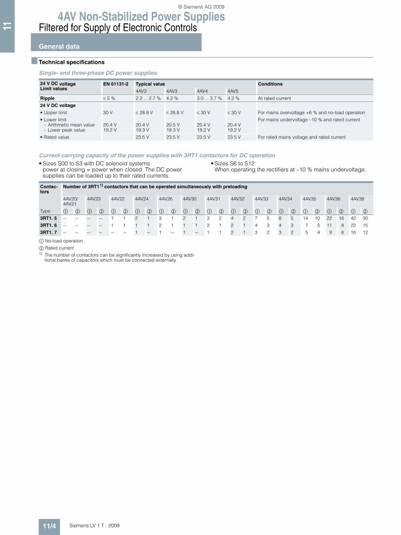
■ Technical specifications
Single- and three-phase DC power supplies
Current-carrying capacity of the power supplies with 3RT1 contactors for DC operation• Sizes S00 to S3 with DC solenoid systems:
power at closing = power when closed. The DC power supplies can be loaded up to their rated currents.
• Sizes S6 to S12: When operating the rectifiers at –10 % mains undervoltage.
$ No-load operation
% Rated current1) The number of contactors can be significantly increased by using addi-
tional banks of capacitors which must be connected externally.
24 V DC voltage EN 61131-2 Typical value ConditionsLimit values 4AV2 4AV3 4AV4 4AV5
Ripple ≤ 5 % 2.2 ... 2.7 % 4.2 % 3.0 ... 3.7 % 4.2 % At rated current
24 V DC voltage
• Upper limit 30 V ≤ 28.8 V ≤ 28.8 V ≤ 30 V ≤ 30 V For mains overvoltage +6 % and no-load operation
• Lower limit For mains undervoltage –10 % and rated current- Arithmetic mean value 20.4 V 20.4 V 20.5 V 20.4 V 20.4 V- Lower peak value 19.2 V 19.3 V 19.3 V 19.2 V 19.2 V
• Rated value 23.5 V 23.5 V 23.5 V 23.5 V For rated mains voltage and rated current
Contac-tors
Number of 3RT11) contactors that can be operated simultaneously with preloading
4AV20/4AV21
4AV23 4AV22 4AV24 4AV26 4AV30 4AV31 4AV32 4AV33 4AV34 4AV35 4AV36 4AV38
Type $ % $ % $ % $ % $ % $ % $ % $ % $ % $ % $ % $ % $ %
3RT1. 5
3RT1. 6
3RT1. 7
--
--
--
--
--
--
--
--
--
--
--
--
1
1
--
1
1
--
2
1
1
1
1
--
3
2
1
1
1
--
2
1
1
1
1
--
3
2
1
2
1
1
4
2
2
2
1
1
7
4
3
5
3
2
8
4
3
5
3
2
14
7
5
10
5
4
22
11
9
16
8
6
42
22
16
30
15
12
LV1T_2009_Gesamtbuch_EN.book Seite 4 Donnerstag, 26. Februar 2009 2:00 14
© Siemens AG 2009

4AV Non-Stabilized Power Supplies
11/5Siemens LV 1 T · 2009
Filtered for Supply of Electronic Controls
General data
11
Primary-side short-circuit protection, secondary-side short-circuit and overload protection
1) In the event of a short-circuit on the feeder lines between the protective device and the input side of the unit, the rated short-circuit breaking capacity of the protection equipment must be taken into account with regard to the maximum possible prospective short-circuit current at the place of installation.
Rectifier unit
Ambient tempera-ture ta
Rated out-put current Id
Primary-side protection against short-circuits (line protection) by means of motor starter protector1) or fuse, gL/gG operational class
Secondary-side protection against short-circuit and over-load by means ofmotor starter protector or fuse, operational class
Type Rated input voltage U1N
575 V (600 V)
500 V 460 V (480 V)
400 V (415 V)
230 V (240 V)
200 V 115 V (120 V)
Type °C DC A Type
Single-phase4AV21 60 1 3RV10 11-@@@10 -- -- -- 0CA 0FA -- 0JA Built-in electrical
short-circuit/overload pro-tection fuse
--Set value in A -- -- -- 0.24 0.4 -- 0.9
40 1.2 3RV10 11-@@@10 -- -- -- 0DA 0FA -- 0KASet value in A -- -- -- 0.29 0.48 -- 1.1
4AV20 3RV10 11-@@@10 -- -- -- 0FA 0HA -- 1BA 3RV10 11-@@@10 1DA60 2.5 Set value in A -- -- -- 0.4 0.6 -- 1.6 Set value in A 2.540 3 Set value in A -- -- -- 0.48 0.72 -- 1.9 Set value in A 3
4AV23 3RV10 11-@@@10 -- -- -- 0HA 0JA -- 1CA Built-in electrical short-circuit/overload pro-tection fuse
--60 3.5 Set value in A -- -- -- 0.55 0.7 -- 240 4.2 Set value in A -- -- -- 0.66 0.84 -- 2.4
4AV22 3RV10 11-@@@10 -- -- -- 0HA 1AA -- 1DA 3RV10 11-@@@10 1GA60 5 Set value in A -- -- -- 0.6 1.1 -- 2.4 Set value in A 540 6 Set value in A -- -- -- 0.72 1.3 -- 2.9 Set value in A 6
4AV24 3RV10 11-@@@10 -- -- -- 1CA 1DA -- 1GA 3RV10 11-@@@10 1KA60 10 Set value in A -- -- -- 1.8 2.4 -- 5 Set value in A 1040 12 Set value in A -- -- -- 2.2 2.9 -- 6 Set value in A 12
4AV26 3RV10 11-@@@10 -- -- -- 1CA 1EA -- 1HA 3RV10 21-@@@10 4BA60 15 Set value in A -- -- -- 2 3.2 -- 6 Set value in A 1540 18 Set value in A -- -- -- 2.4 3.8 -- 7.2 Set value in A 18
4AV41 01 40 1.5 3RV10 11-@@@10 -- -- -- 0BA 0DA -- -- Integrated blade-type fuse FK2
4 ASet value in A -- -- -- 0.15 0.27 -- --Fuse gL/gG A -- -- -- 0.5 1 -- --
4AV41 03 40 3 3RV10 11-@@@10 -- -- -- 0GA 0HA -- -- Integrated blade-type fuse FK2
7.5 ASet value in A -- -- -- 0.5 0.7 -- --Fuse gL/gG A -- -- -- 1 2 -- --
4AV41 06 40 6 3RV10 11-@@@10 -- -- -- 0JA 0KA -- -- Integrated blade-type fuse FK2
15 ASet value in A -- -- -- 0.8 1.2 -- --Fuse gL/gG A -- -- -- 2 1 -- --
4AV41 10 40 10 3RV10 11-@@@10 -- -- -- 1BA 1CA -- -- Integrated blade-type fuse FK2
25 ASet value in A -- -- -- 1.6 2.4 -- --Fuse gL/gG A -- -- -- 4 4 -- --
Three-phase4AV30 3RV10 11-@@@10 0FA 0FA 0FA 0HA 0KA 0KA -- 3RV10 11-@@@10 1KA
60 9/10 Set value in A 0.4 0.4 0.4 0.6 1 1 -- Set value in A 9/1040 11/12 Set value in A 0.48 0.48 0.48 0.72 1.2 1.2 -- Set value in A 11/12
4AV31 3RV10 11-@@@10 0HA 0HA 0HA 0KA 1BA 1CA -- 3RV10 21-@@@10 4BA60 13.5/15 Set value in A 0.6 0.6 0.6 1 1.6 2 -- Set value in A 14/1540 16/18 Set value in A 0.72 0.72 0.72 1.2 1.9 2.4 -- Set value in A 16/18
4AV32 3RV10 11-@@@10 0HA 0KA 0KA 0KA 1BA 1DA -- 3RV10 31-@@@10 4DA60 18/20 Set value in A 0.6 1 1 1 1.6 2.4 -- Set value in A 18/2040 21.5/24 Set value in A 0.72 1.2 1.2 1.2 1.9 2.9 -- Set value in A 21.5/24
4AV33 3RV10 11-@@@10 1CA 1CA 1CA 1CA 1EA 1FA -- 3RV10 31-@@@10 4FA60 27/30 Set value in A 1.8 1.8 1.8 2 3.2 4 -- Set value in A 28/3040 32.5/36 Set value in A 2.2 2.2 2.2 2.4 3.8 4.8 -- Set value in A 32.5/36
4AV34 3RV10 11-@@@10 1CA 1CA 1CA 1DA 1GA 1GA -- 3RV10 41-@@@10 4HA60 36/40 Set value in A 2 2 2 2.4 5 5 -- Set value in A 36/4040 43/48 Set value in A 2.4 2.4 2.4 2.9 6 6 -- Set value in A 43/48
4AV35 3RV10 11-@@@10 1DA 1DA 1EA 1FA 1HA 1HA -- 3RV10 41-@@@10 4JA60 45/50 Set value in A 2.4 2.4 3.2 4 6 6 -- Set value in A 45/5040 54/60 Set value in A 2.9 2.9 3.8 4.8 7.2 7.2 -- Set value in A 54/60
4AV36 3RV10 11-@@@10 -- 1HA -- 1HA -- -- -- 3RV10 41-@@@10 4MA60 80 Set value in A -- 6 -- 6 -- -- -- Set value in A 8040 96 Set value in A -- 7.2 -- 72 -- -- -- Set value in A 96
4AV38 60 150 3RV10 11-@@@10 -- 1KA -- 1KA -- -- -- 3VL27 16-1DC33-0AA0Set value in A -- 10 -- 12 -- -- -- Set value in A 150/800
40 180 3RV10 21-@@@10 -- 4AA -- 4AA -- -- -- 3VL37 20-1DC36-0AA0Set value in A -- 12 -- 14 -- --- -- Set value in A 180/1000
4AV51 25 40 25 3RV10 11-@@@10 -- -- -- 1BA -- -- -- 3RV10 31-@@@10 4EASet value in A -- -- -- 1.6 -- -- -- Set value in A 25Fuse gL/gG A -- -- -- 2 -- -- -- Fuse gL/gG A 25
4AV51 35 40 35 3RV10 11-@@@10 -- -- -- 1CA -- -- -- 3RV10 31-@@@10 4FASet value in A -- -- -- 2.4 -- -- -- Set value in A 35Fuse gL/gG A -- -- -- 4 -- -- -- Fuse gL/gG A 35
LV1T_2009_Gesamtbuch_EN.book Seite 5 Donnerstag, 26. Februar 2009 2:00 14
© Siemens AG 2009

4AV Non-Stabilized Power SuppliesFiltered for Supply of Electronic Controls4AV2, 4AV4 power supplies,filtered, single-phase
11/6 Siemens LV 1 T · 2009
11
■ Overview
• Rated output voltage U2N 24 V DC according to EN 61131-21) and SIMATIC at input voltage +6 % to –10 % and load 0 % to 100 %
• Safety transformer according to EN 61558-2-6• 4AV21, 4AV23: CUUS at 60 °C, ¢;
4AV20, 4AV22, 4AV24, 4AV26: CUUS at 60 °C, ·;4AV41: ¢
• 4AV2: ta = max. 60 °C/B, 4AV41: ta = 40 °C/B
• Varistor suppressor circuit• Status LED• EMC according to EN 62041:
- 4AV2: Suitable for connection to the public supply (residential environments) and industrial networks (industrial environ-ments):
- 4AV4: Suitable for connection to industrial networks (indus-trial environments)
• Ripple < 5 %
4AV21, 4AV23 (left) and 4AV20, 4AV22 to 4AV24 (right)
1) EN 61131-2: equipment specification for power supply and interface for programmable controllers. For limit values for 24 V DC see "Technical specifications".
■ Schematics
Terminal designations and terminal assignments
1) For Cage Clamp terminals, the ground connection is routed to the terminal. The order of terminal assignments then changes as follows .
Rated input voltage U1N
Primary connections and links
Rated voltage U1N
Terminals Links
V V
4AV21 02, 4AV23 02 4AV21 06, 4AV23 06
Type 4AV21 02 and 4AV23 02
230 (240) - 115 (120)
230 (240)
115 (120)
1-4
1-4
2-3
1-3, 2-4
Type 4AV21 06 and 4AV23 06
400 (415) 400 (415) 1-2 --
Type 4AV2. 00
400 (415) - 230 (240)± 15
415
400 (415)
385
245
230 (240)
215
5-3
1-3
4-3
5-2
1-2
4-2
--
--
--
--
--
--
Type 4AV2. 01
400 (415) - 230 (240) - 115 (120)
400 (415)
230 (240)
115 (120)
1-5
1-4
1-4
2-3
2-3
1-3, 2-4
Type 4AV41
400 230 ± 15
415
400
385
245
230
215
400 V + 15 V
400 V 0 V
400 V – 15 V
230 V + 15 V
230 V 0 V
230 V – 15 V
--
--
--
--
--
--
1
23
4
31
32
NSF0_00045c
1 2 3 4
32 31
1
2
31
32
NSF0_00046c
32 31
1 2
NSF0_00047b
31
32
1
32
4
5 31
1 2 3
31 31 32
4 5
1)
45
31
32
123
31
NSF0_00048b
1 2 3 4 5
31 31 32 1)
NSF0_00178a
+15 V
M
L+
M
M M L+
400 V230 V
-15 V 0 V+15 V
0 V -15 V 230 V 400 V
1)
1 2NSF0_00183
LV1T_2009_Gesamtbuch_EN.book Seite 6 Donnerstag, 26. Februar 2009 2:00 14
© Siemens AG 2009
4AV Non-Stabilized Power Supplies
11/7Siemens LV 1 T · 2009
Filtered for Supply of Electronic Controls4AV3, 4AV5 power supplies,
filtered, three-phase
11
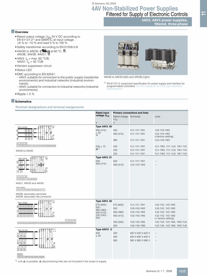
■ Overview
• Rated output voltage U2N 24 V DC according to EN 61131-21) and SIMATIC at input voltage +6 % to –10 % and load 0 % to 100 %
• Safety transformer according to EN 61558-2-6• 4AV30 to 4AV35: CUUS at 60 °C, ·;
4AV36, 4AV38, 4AV51: ·• 4AV3: ta = max. 60 °C/B,
4AV51: ta = 40 °C/B• Varistor suppressor circuit• Status LED• EMC according to EN 62041:
- 4AV3: suitable for connection to the public supply (residential environments) and industrial networks (industrial environ-ments)
- 4AV5: suitable for connection to industrial networks (industrial environments)
• Ripple < 5 %
4AV30 to 4AV33 (left) and 4AV38 (right)
1) EN 61131-2: equipment specification for power supply and interface for programmable controllers. For limit values for 24 V DC see "Technical specifications".
■ Schematics
Terminal designations and terminal assignments
1) Link d is possible, d disconnecting links are not included in the scope of supply.
Rated input voltage U1N
Primary connections and links
Rated voltage U1N
Terminals Links
V V
4AV30 to 4AV35
Type 4AV3. 00
400 (415)± 20 *
420
400 (415)
380
1U1-1V1-1W1
1U1-1V1-1W1
1U1-1V1-1W1
1U2-1V2-1W2
1U4-1V4-1W4 (=factory setting)
1U3-1V3-1W3
230 ± 10d
1)240
230
220
1U1-1V1-1W1
1U1-1V1-1W1
1U1-1V1-1W1
1U1-1W2, 1V1-1U2, 1W1-1V2
1U1-1W4, 1V1-1U4, 1W1-1V4
1U1-1W3, 1V1-1U3, 1W1-1V3
4AV31, 4AV33 and 4AV35
4AV36: secondary terminals 4AV38: secondary flat connector
Type 4AV3. 01
500-400 (415)
500
400 (415)
1U1-1V1-1W1
1U3-1V3-1W3
--
--
Type 4AV3. 02
575 (600) - 500 - 460 (480) - 400 (415) - 230 (240) - 200
575 (600)
500
460 (480)
400 (415)
230 (240)
200
1U1-1V1-1W1
1U3-1V3-1W3
1U4-1V4-1W4
1U5-1V5-1W5
1U5-1V5-1W5
1U6-1V6-1W6
1U2-1V2, 1V2-1W2
1U2-1V2, 1V2-1W2
1U2-1V2, 1V2-1W2
1U2-1V2, 1V2-1W2 (= factory setting)
1U2-1V5, 1V2-1W5, 1W2-1U5
1U2-1V6, 1V2-1W6, 1W2-1U6
Type 4AV51 .5
400± 20
420
400
380
420 V-420 V-420 V
400 V-400 V-400 V
380 V-380 V-380 V
--
--
--
31
32
31
1U1
1U3
1U4
1U2
1V1
1V3
1V4
1V2
1W1
1W3
1W4
1W2
NSF0_00049b
1V31U2 1V11U41U1 1U3 1W21W31W41W11V4 1V2
31 31 32
NSF0_00052a
1W1
1V1
1U1 31
32
31
1W3
1V3
1U3
1W31V3 1W11V11U1 1U3
31 31 32
� � �� � � � � �� � �� � � � � � � � � �� �
� � � � � � � �
1U1 31
32
31
1U3
1U4
1U5
1U6
1U2
1V1
1V3
1V4
1V5
1V6
1V2
1W1
1W3
1W4
1W5
1W6
1W2
NSF0_00055b
1U21U5 1U61U41U1 1U3 1V21V5 1V61V41V1 1V3 1W21W5 1W61W41W11W3
31 31 32
�
�
�����
�����
�����
� � � � � � � � �
�����
�����
�����
�����
�����
�����
�
� � �
� �
� � � � � � � � � � � � � � � � � � � � � � � �
�
LV1T_2009_Gesamtbuch_EN.book Seite 7 Donnerstag, 26. Februar 2009 2:00 14
© Siemens AG 2009
4AV Non-Stabilized Power SuppliesUnfiltered for Supply of General Loads4AV98 power supplies,unfiltered, single-phase
11/8 Siemens LV 1 T · 2009
11
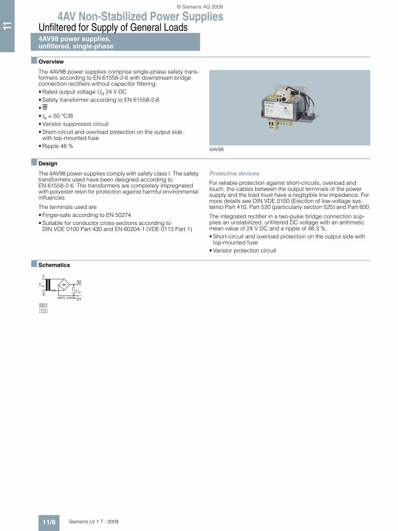
■ Overview
The 4AV98 power supplies comprise single-phase safety trans-formers according to EN 61558-2-6 with downstream bridge connection rectifiers without capacitor filtering.• Rated output voltage Ud 24 V DC• Safety transformer according to EN 61558-2-6•¢ • ta = 50 °C/B• Varistor suppressor circuit• Short-circuit and overload protection on the output side
with top-mounted fuse• Ripple 48 %
4AV98
■ Design
The 4AV98 power supplies comply with safety class I. The safety transformers used have been designed according to EN 61558-2-6. The transformers are completely impregnated with polyester resin for protection against harmful environmental influences.
The terminals used are• Finger-safe according to EN 50274• Suitable for conductor cross-sections according to
DIN VDE 0100 Part 430 and EN 60204-1 (VDE 0113 Part 1)
Protective devices
For reliable protection against short-circuits, overload and touch, the cables between the output terminals of the power supply and the load must have a negligible line impedance. For more details see DIN VDE 0100 (Erection of low-voltage sys-tems) Part 410, Part 520 (particularly section 525) and Part 600.
The integrated rectifier in a two-pulse bridge connection sup-plies an unstabilized, unfiltered DC voltage with an arithmetic mean value of 24 V DC and a ripple of 48.3 %.• Short-circuit and overload protection on the output side with
top-mounted fuse• Varistor protection circuit
■ Schematics
2
132
1N
d
31NSF0_00056a
1 2
32 31
LV1T_2009_Gesamtbuch_EN.book Seite 8 Donnerstag, 26. Februar 2009 2:00 14
© Siemens AG 2009

4AV Non-Stabilized Power Supplies
11/9Siemens LV 1 T · 2009
Unfiltered for Supply of General Loads4AV96 power supplies,unfiltered, three-phase
11
■ Overview
The 4AV96 power supplies comprise three-phase safety trans-formers according to EN 61558-2-6 with downstream bridge connection rectifiers without capacitor filtering.• Rated output voltage Ud 30-27-24 V DC• Safety transformer according to EN 61558-2-6•·• Shield winding between input and output winding• Varistor suppressor circuit• Designed and approved according to VW equipment
specification• Ripple < 5 %
4AV96
■ Design
The 4AV96 power supplies comply with safety class I. The safety transformers used have been designed according to EN 61558-2-6. The transformers are completely impregnated with polyester resin for protection against harmful environmental influences.
The terminals used are• Finger-safe according to EN 50274• Suitable for conductor cross-sections according to
DIN VDE 0100 Part 430 and EN 60204-1 (VDE 0113 Part 1)
Protective devices
For reliable protection against short-circuits, overload and touch, the cables between the output terminals of the power supply and the load must have a negligible line impedance. For more details see DIN VDE 0100 (Erection of low-voltage sys-tems) Part 410, Part 520 (particularly section 525) and Part 600.
The integrated rectifier in a six-pulse bridge connection supplies an unstabilized, unfiltered DC voltage with an arithmetic mean value of 30/27/24 V DC and a ripple of < 5 %.• Shield winding between input and output winding• Varistor protection circuit • In accordance with VW equipment specification
■ Technical specifications
Primary-side short-circuit and overload protection
■ Schematics
Rectifier unit Rated output current Id
Primary-side short-circuit and overload protection by motor starter protectors
Motor starter protector
Set value at400 V AC
Type DC A Type A
4AV96 04-1CB00-2N 4 3RV10 11-0EA10 0.28
4AV96 04-5CB00-2N 12 3RV10 11-0JA10 0.8
4AV96 04-2CB00-2N 25 3RV10 11-1CA10 1.8
+5%U-5%N
+5%V-5%
+5%W-5%
3027 24V-PE1N
d
NSF0_00057a
LV1T_2009_Gesamtbuch_EN.book Seite 9 Donnerstag, 26. Februar 2009 2:00 14
© Siemens AG 2009

4AV Non-Stabilized Power Supplies
Project planning aids
11/10 Siemens LV 1 T · 2009
11
■ Dimensional drawings
Filtered for supply of electronic controls
4AV2, 4AV4 power supplies, filtered, single-phase
4AV21, 4AV23,for horizontal mounting position, snap-on mounting onto standard mounting rail TH 35 × 7.5 according to EN 60715
4AV20, 4AV22, 4AV24, 4AV26for any mounting position,horizontal mounting position for standard mounting rail mounting
B 6 111
136
72N
SF0
_002
45
2
1
1
2
Flat connector DIN 46244-A 6,3-0,8Screw terminal: Solid 0.5 mm2 … 6 mm2,Finely stranded 0.5 mm2 … 4 mm2
21
Rated current
A DC
4AV214AV23
Type
4572
B
1 3,5
b1l2n1n2 d1
b2b3
h 1
l1
NS
F0_0
0246
b1n1
3
6
5
4
2
1
n 1d2
n2
Screw terminal: for 4AV20 to 4AV24solid 0.2 mm2 … 4 mm2,finely stranded 0.2 mm2 … 2.5 mm2
for 4AV26 solid or finely stranded0.5 mm2 … 10 mm2
Cage Clamp terminal:for 4AV20 to 4AV24solid or finely stranded 0.08 mm2 … 2.5 mm2
for 4AV26 solid or finely stranded 0.2 mm2 … 6 mm2
Flat connectorDIN 46244-A 6,3-0,8Screw terminal: solid 0.5 mm2 … 6 mm2,finely stranded 0.5 mm2 … 4 mm2
Screw terminal: solid or finely stranded 2.5 mm2
Cage Clamp terminal (also ground terminal) from the top:solid or finely stranded 0.08 mm2 … 4 mm2
Rated current A DC
4AV204AV224AV244AV26
2,5 51015
Type
EI 84/42EI 105/60EI 120/72EI 150N/58
Designation according to DIN 41302
b1 d2 h1 I1 n1 n2
89103123110,5
100113128140
M4M5M5M6
142157170200
84105120150
64 83104 90
64 80,5 90122
51606758
4,8 x 95,8 x 95,8 x 97 x 13
b2 b3 d1
4AV2. ..-0A 4AV2. ..-1A
4AV20 with integrated standard rail mounting
2
1
3
Input Output
4
5
6
Mounting hole
LV1T_2009_Gesamtbuch_EN.book Seite 10 Donnerstag, 26. Februar 2009 2:00 14
© Siemens AG 2009
4AV Non-Stabilized Power Supplies
11/11Siemens LV 1 T · 2009
Project planning aids
11
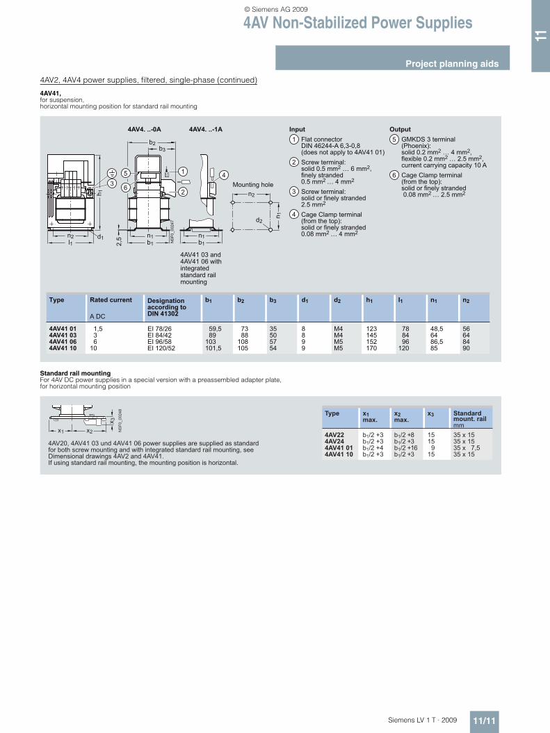
4AV2, 4AV4 power supplies, filtered, single-phase (continued)
4AV41, for suspension,horizontal mounting position for standard rail mounting
Standard rail mounting For 4AV DC power supplies in a special version with a preassembled adapter plate, for horizontal mounting position
NS
F0_0
0247
b1l1n1n2 d1
b2b3
h 1
b1n1
5 41
2,5
263
n 1d2
n2
GMKDS 3 terminal(Phoenix):solid 0.2 mm2 … 4 mm2,flexible 0.2 mm2 … 2.5 mm2,current carrying capacity 10 A Cage Clamp terminal (from the top):solid or finely stranded 0.08 mm2 … 2.5 mm2
Flat connectorDIN 46244-A 6,3-0,8(does not apply to 4AV41 01)Screw terminal: solid 0.5 mm2 … 6 mm2,finely stranded 0.5 mm2 … 4 mm2
Screw terminal: solid or finely stranded 2.5 mm2
Cage Clamp terminal (from the top):solid or finely stranded 0.08 mm2 … 4 mm2
Rated current
A DC
4AV41 014AV41 034AV41 064AV41 10
1,5 3 610
Type
EI 78/26EI 84/42EI 96/58EI 120/52
Designation according to DIN 41302
b1 d2 h1 I1 n1 n2
59,5 89103101,5
73 88108105
M4M4M5M5
123145152170
78 84 96120
48,56486,585
56648490
35505754
8899
b2 b3 d1
4AV4. ..-0A 4AV4. ..-1A
4AV41 03 and 4AV41 06 with integrated standard rail mounting
2
1
3
Input Output
4
5
6Mounting hole
x1 NS
F0_0
0248
x2
x 3
4AV224AV244AV41 014AV41 10
1515 915
b1/2 +3b1/2 +3b1/2 +4b1/2 +3
b1/2 +8b1/2 +3b1/2 +16b1/2 +3
35 x 1535 x 1535 x 7,535 x 15
Standard mount. railmm
Type
4AV20, 4AV41 03 und 4AV41 06 power supplies are supplied as standard for both screw mounting and with integrated standard rail mounting, see Dimensional drawings 4AV2 and 4AV41.If using standard rail mounting, the mounting position is horizontal.
x1max.
x2max.
x3
LV1T_2009_Gesamtbuch_EN.book Seite 11 Donnerstag, 26. Februar 2009 2:00 14
© Siemens AG 2009

4AV Non-Stabilized Power Supplies
Project planning aids
11/12 Siemens LV 1 T · 2009
11
4AV3, 4AV5 power supplies, filtered, three-phase
4AV30 to 4AV33, arrangement: 60 °C ambient temperature on vertical surfaces 40 °C ambient temperature on horizontal surfaces
4AV34, 4AV35, arrangement: 60 °C ambient temperature on horizontal surfaces 40 °C ambient temperature on vertical surfaces
NS
F0_0
0249
n3
l1
n2
l2
d1
b2b3
h 1
b1n1
5
1
2
3
l3l4
4
n 1d2
n2n3
4AV304AV314AV324AV33
10152030
3UI 75/253UI 75/403UI 90/303UI 90/50
68817195
M5M5M6M6
190190220220
136136162162
164164216216
200200232232
110110124124
48635575
113113136136
150150200200
115115115158
72 65 70102
d1
5,8 x 115,8 x 117 x 137 x 13
h1 I1 n1 n3n2d2 I2 I3 I4Type b1 b2 b3Designation according to DIN 41302
Rated current
A DC
Flat connector DIN 46244-A 6,3-0,8Screw terminal:solid or finely stranded 0.5 mm2 … 4 mm2
Screw terminal: solid or finely stranded 2.5 mm2
Screw terminal:solid or finely stranded 0.5 mm2 … 10 mm2
Option: back-up capacitor
21
3
Input
Output4
5
Mounting hole
2
260
NS
F0_0
0250
266
170198
n3d1
b2b3
b1
5
3
l1
4
n2 n1
1
n 1d2
n2n3
Rated current
A DC
4AV344AV35
4050
Type
3UI 114/383UI 114/62
Designation according to DIN 41302
d2 I1 n1 n3n2
165190
M6M6
287295
7094
176176
250250
115127
7 x 117 x 11
b2 b3 d1b1
90114
Flat connector DIN 46244-A 6,3-0,8Screw terminal: solid or finely stranded 0.5 mm2 … 4 mm2
Screw terminal: solid or finely stranded 2.5 mm2
Screw terminal:solid 1 mm2 … 16 mm2,finely stranded 2.5 mm2 … 16 mm2
Option: back-up capacitor
21
3
Input
Output4
5
Mounting hole
LV1T_2009_Gesamtbuch_EN.book Seite 12 Donnerstag, 26. Februar 2009 2:00 14
© Siemens AG 2009

4AV Non-Stabilized Power Supplies
11/13Siemens LV 1 T · 2009
Project planning aids
11
4AV3, 4AV5 power supplies, filtered, three-phase (continued)
4AV36 (80 A)for arrangement on vertical surfaces, cooling fins vertical
4AV38 (150 A) for arrangement on vertical surfaces, cooling fins vertical
4AV51 for standing/hanging mounting position
1
NS
F0_0
0251
176
258295
182
255
10
45
290
176
258
M8
Permissible uninterrupted current when arranged on horizontal surfaces:52 A at ta = 60 °C80 A at ta = 25 °C
Screw terminal: solid 0.5 mm2 … 6 mm2,finely stranded 0.5 mm2 … 4 mm2(with or without end sleeve)
Screw terminal: solid 4 mm2 … 16 mm2,finely stranded 6 mm2 … 35 mm2(with or without end sleeve)
2
1Input
Output
Mounting hole
2
370
NS
F0_0
0252
1
380298
18
10
20034
010
5
+-
200
298
M8
Permissible uninterrupted current when arranged on horizontal surfaces:100 A at ta = 60 °C150 A at ta = 25 °C
Screw terminal: solid 0.5 mm2 … 6 mm2,finely stranded 0.5 mm2 … 4 mm2(with or without end sleeve)
Flat connector2
1Input
OutputFlat connectors with through-hole for M8 screwCan be used for 3TX6 526-3B terminal cover
Mounting hole
2
NS
F0_0
0253
l1n3n2 d1
b3
h 1
b1n1
2,5
1
4
3
b2
n 1d2
n2n3
3
Rated current
A DC
4AV51 254AV51 35
2535
Type
3UI 90/503UI 114/38
Designation according to DIN 41302
b1 d2 h1 I1 n1 n2 n3
9690
6874
240294
216266
7670
136176
200250
1111
M6M6
b2 d1
Flat connector DIN 46244-A 6,3-0,8Screw terminal: solid 0.5 mm2 … 6 mm2,finely stranded 0.5 mm2 … 4 mm2
Screw terminal: solid or finely stranded 2,5 mm2
LUL 10.16 terminal (Weidmüller):solid 0.5 mm2 … 10 mm2,flexible 0.5 mm2 … 10 mm2
21
Input
Output4
8478
b3
Mounting hole
LV1T_2009_Gesamtbuch_EN.book Seite 13 Donnerstag, 26. Februar 2009 2:00 14
© Siemens AG 2009

4AV Non-Stabilized Power Supplies
Project planning aids
11/14 Siemens LV 1 T · 2009
11
Unfiltered for supply of general loads
4AV98 power supplies, unfiltered, single-phase
4AV98 00 and 4AV98 02 for any mounting position
4AV98 06 and 4AV98 07 for any mounting position
b1h1n2
2
NS
F0_0
0254
d1l 1n 1
11
3
n 1
d2n2
Rated power
W
4AV98 00-5CB..,4AV98 02-5CB..
500
Type
EI 150N/48
Designation according to DIN 41302
I1 n1 Fusesn2
6,8 228 200 174M6 160
d1 d2 h1b1
193
Flat connector DIN 46244-A 6,3-0,8Screw terminal: solid 0.5 mm2 … 6 mm2,finely stranded 0.5 mm2 … 4 mm2
D fuse DIN 49360
21
3
3
Mounting hole
NS
F0_0
0255
b1
h 1
n22 d1
l 1 n 1
b1
h 16
431
n 1
d2n2
1
Rated power
W
4AV98 06-4CB..4AV98 07-0CB..4AV98 06-5CB..4AV98 07-1CB..4AV98 06-6CB..4AV98 07-2CB..4AV98 06-7CB..4AV98 07-3CB..4AV98 06-8CB..4AV98 07-4CB..
50 50 80 80125125200200315315
Type
EI 78/26EI 78/26EI 84/42EI 84/42EI 96/44EI 96/44EI 96/58EI 96/58EI 120/52EI 120/52
Designation according to DIN 41302
I1 n1 Fusesn2
93 93102102104104118118107107
48.548.563.563.5737386.586.58585
56566464848484849090
M4M4M4M4M5M5M5M5M5M5
96 96101101113113113113134134
d2 h1
4.8 x 94.8 x 94.8 x 94.8 x 95.8 x 115.8 x 115.8 x 115.8 x 115.8 x 115.8 x 11
116116122122133133138138197197
d1b1
Flat connector DIN 46244-A 6.3-0.8Screw terminal: solid 0.5 mm2 … 6 mm2,Finely stranded 0.5 mm2 … 4 mm2
G fuse DIN VDE 0820 Part 22D fuse DIN 49360
2
34
333333
3344
Mounting hole
LV1T_2009_Gesamtbuch_EN.book Seite 14 Donnerstag, 26. Februar 2009 2:00 14
© Siemens AG 2009
4AV Non-Stabilized Power Supplies
11/15Siemens LV 1 T · 2009
Project planning aids
11
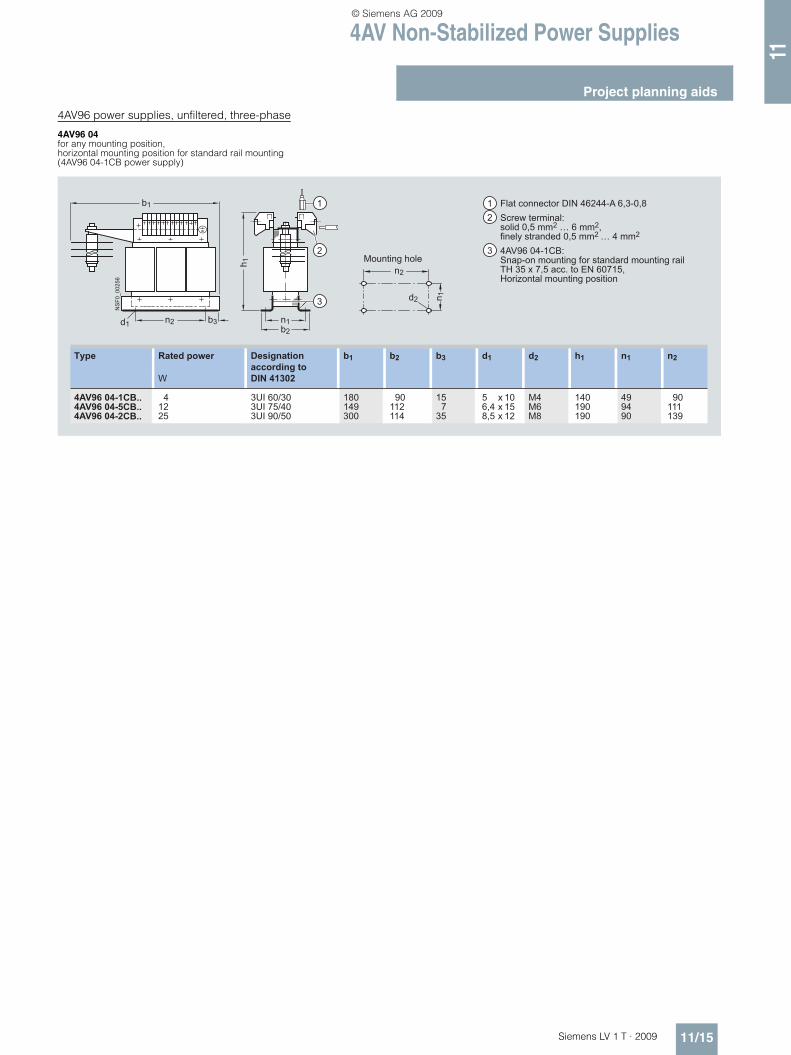
4AV96 power supplies, unfiltered, three-phase
4AV96 04 for any mounting position,horizontal mounting position for standard rail mounting(4AV96 04-1CB power supply)
NS
F0_0
0256
b1
n2
2
d1
h 1
1
b3 n1b2
3 n 1d2
n2
Rated power
W
4AV96 04-1CB..4AV96 04-5CB..4AV96 04-2CB..
41225
Type
3UI 60/303UI 75/403UI 90/50
Designation according to DIN 41302
90112114
b2
180149300
15 735
5 x 106,4 x 158,5 x 12
b3 d1b1 d2 h1 n1 n2
M4M6M8
140190190
499490
90111139
Flat connector DIN 46244-A 6,3-0,8Screw terminal: solid 0,5 mm2 … 6 mm2,finely stranded 0,5 mm2 … 4 mm2
4AV96 04-1CB:Snap-on mounting for standard mounting rail TH 35 x 7,5 acc. to EN 60715,Horizontal mounting position
21
3Mounting hole
LV1T_2009_Gesamtbuch_EN.book Seite 15 Donnerstag, 26. Februar 2009 2:00 14
© Siemens AG 2009

4AV Non-Stabilized Power Supplies
Notes
11/16 Siemens LV 1 T · 2009
11
7
LV1T_2009_Gesamtbuch_EN.book Seite 16 Donnerstag, 26. Februar 2009 2:00 14
© Siemens AG 2009


![Genetic Characterization of Shigella flexneri Isolates in ...stacks.cdc.gov/view/cdc/27353/cdc_27353_DS1.pdf · serotype 4av(1973GZ03)and Yv(1978GZ01), recently described bySunetal[13–15],](https://static.fdocuments.net/doc/165x107/5f39c0195608ec074d7a3b6e/genetic-characterization-of-shigella-flexneri-isolates-in-serotype-4av1973gz03and.jpg)