Trane TCONT802AS32DA Touch Screen and TCONT803AS32DA Touch Screen

Lumio Touch Screen Manual Assembly
User Guide
Version A4 3/2013
DO070201003

6355 Topanga Canyon Blvd. Suite #335, Woodland Hills CA, 91367 USA. Tel: +1 877 97 LUMIO Fax: +1 818 883 0858. Website: www.lumio.com
DO070201003
6355 Topanga Canyon Blvd. Suite #335, Woodland Hills CA, 91367 USA. Tel: +1 877 97 LUMIO Fax: +1 818 883 0858. Website: www.lumio.com
Document Revision History Release Date
July 2011
Revision History
AO
A1 September 2012 • Modified glass requirements • Added Master Bond epoxy pictures
A2 December 2012 Added FFC – sensor connectivity instructions A3 January 2013 General Revision including:
• Work Flow • Tools and Materials • LED Wiring • Flat cable connection • Added Distribution Ready Procedure • OQC • Removed Glassless Assembly • General editing
A4 March 2013 • General Editing • Edited Workflow • Added procedure for attaching sensors to panels • Added Index, Table of Figures, Table of Tables
This Lumio Touch Screen Manual Assembly User Guide is designed for use by qualified technicians at Lumio authorized customers. Users must read and familiarize themselves entire manual before manually assembling Lumio Touch Screens. Documentation Copyright Information herein is proprietary information and a trade secret of Lumio Inc. © Copyright 2011 by Lumio Inc. All rights reserved. Disclaimer The information in this manual has been carefully examined and is believed to be reliable. Lumio Inc. shall not be liable for any direct, indirect, incidental, special, exemplary, or consequential damages of any kind, however incurred, through the use of this product. Lumio Inc. reserves the right to make changes to any of its products in order to improve reliability, design and performance. The text and drawings herein are for the purposes of illustration and reference only; the text, drawings and specifications on which they are based are subject to change without notice. Warning Use only Lumio approved parts and materials. Use of non-Lumio approved materials may impair the assembly and operation of Touch Screens. Technical Assistance For technical questions and troubleshooting assistance: Contact the Lumio office closest to you. Visit us at our website: www.lumio.com. E-mails may be sent to: [email protected]. Contact Lumio Inc 6355 Topanga Canyon Blvd. #335, Woodland Hills, CA, USA 91367 Ph: +1 818 715 9866, Fax: +1 818 715 9853, http://www.lumio.com Email: [email protected]

6355 Topanga Canyon Blvd. Suite #335, Woodland Hills CA, 91367 USA. Tel: +1 877 97 LUMIO Fax: +1 818 883 0858. Website: www.lumio.com 6355 Topanga Canyon Blvd. Suite #335, Woodland Hills CA, 91367 USA. Tel: +1 877 97 LUMIO Fax: +1 818 883 0858. Website: www.lumio.com
DO070201003
6355 Topanga Canyon Blvd. Suite #335, Woodland Hills CA, 91367 USA. Tel: +1 877 97 LUMIO Fax: +1 818 883 0858. Website: www.lumio.com
Contents Chapter 1 Introduction ...................................................................................................................................2 1.1 Safety Warnings and Precautions ................................................................................................................... 2 1.2 Reference Guides ............................................................................................................................................ 2 Chapter 2 Active Barrier Overview ..................................................................................................................3 Chapter 3 Work Flow .....................................................................................................................................5 Chapter 4 IQC: Incoming Quality Control ........................................................................................................6 4.1 Incoming Components Inspection .................................................................................................................. 6 4.2 Incoming Glass Panel Inspection .................................................................................................................... 7 4.3 General ........................................................................................................................................................... 7 4.4 Cleaning .......................................................................................................................................................... 7 4.5 Inspection Requirements................................................................................................................................ 7 4.6 Mechanical Requirements .............................................................................................................................. 8
4.6.1 Types of Glass .........................................................................................................................................8 4.6.2 Circular and Linear Defect Criteria .........................................................................................................8 4.6.3 Acceptance / Rejection Criteria for Glass Defects ..................................................................................9 4.6.4 Glass Crack Criteria .................................................................................................................................9 4.6.5 Glass Surface Flatness ......................................................................................................................... 10 4.6.6 Glass Flatness Test ............................................................................................................................... 10 4.6.7 Glass Flatness Test Components ......................................................................................................... 11 4.6.8 Glass Flatness Test Process.................................................................................................................. 11 4.6.9 Placing Components on Glass .............................................................................................................. 11
Chapter 5 Pre-Assembly: Assembling the Active Barrier ................................................................................ 12 5.1 Requirements ............................................................................................................................................... 12 5.2 Assembling the Active Barrier for Dual Sensor Systems .............................................................................. 12 5.3 Assembling the Active Barrier for Quad Sensor Systems ............................................................................. 17 Chapter 6 Attaching the Active Barrier to the Touch Screen Glass Panel ........................................................ 18 Chapter 7 LED PCB Wiring............................................................................................................................. 21 7.1 LED PCB wiring for Dual Sensor Systems ...................................................................................................... 21 7.2 LED Wiring for Quad Sensor systems ........................................................................................................... 24 7.3 LED Wiring for Quad Sensor Systems without an Extension PCB Controller ............................................... 24 7.4 LED Wiring for Quad Sensor Systems with an Extension PCB Controller ..................................................... 25 Chapter 8 Attaching Sensors to the Touch Screen Glass Panel ....................................................................... 26 8.1 Attaching Sensors to the Glass Panel with Dymax 3069 Epoxy .................................................................... 27 8.2 Attaching Sensors to the Glass Panel with DP 105 Epoxy ............................................................................ 31 Chapter 9 Connecting the Sensors to the PCB Controller ............................................................................... 34 9.1 Connecting Jenoptic Sensors ........................................................................................................................ 34 9.2 Connecting 2 KC Sensors .............................................................................................................................. 36
9.2.1 Direct 2 KC Sensor - PCB Controller Connection ................................................................................. 37 9.2.2 Connecting a 2 KC Sensor to a PCB Controller with a Flat Cable Adaptor ......................................... 38
Chapter 10 Connecting the PCB Controller to the Extension PCB Controller ................................................... 40 Chapter 11 Distribution Ready Procedure ..................................................................................................... 42 Chapter 12 OQC Outgoing Quality Control .................................................................................................... 42 12.1 Glass Inspection ................................................................................................................................... 42 12.2 Cleaning ............................................................................................................................................... 42 12.3 Mechanical Criteria .............................................................................................................................. 43 12.4 Glass Crack Criteria .............................................................................................................................. 44 12.5 Components Inspection ....................................................................................................................... 44 12.6 Touch Screen Dimension Verification ................................................................................................. 45 Chapter 13 Appendix A: Sensor Adhesion Requirements ............................................................................... 46

1
Introduction DO070201003
6355 Topanga Canyon Blvd. Suite #335, Woodland Hills CA, 91367 USA. Tel: +1 877 97 LUMIO Fax: +1 818 883 0858. Website: www.lumio.com
13.1 Sensor Adhesion Requirements .......................................................................................................... 46 13.2 Primers ................................................................................................................................................. 46 13.3 Types of Adhesives .............................................................................................................................. 47 13.4 Adhesive Curing Requirements ........................................................................................................... 48
13.4.1 Glue Curing Tool Power Density .......................................................................................................... 48 13.4.2 Glue Curing Time ................................................................................................................................. 48 13.4.3 Lumio UV Glue Curing Tool .................................................................................................................. 48
Chapter 14 Appendix B: Installing Crystal Touch Manager ............................................................................. 49 14.1 Installing Crystal Touch Manager ........................................................................................................ 49 14.2 Resolving Permission Issues for Vista and Win 7 OS ........................................................................... 49 Chapter 15 Appendix C: Creating a 1 mm gap between the Sensor and the Active Barrier .............................. 51 15.1 Overview .............................................................................................................................................. 51 15.2 Tools .................................................................................................................................................... 51 15.3 Materials .............................................................................................................................................. 51 15.4 Creating a 1 mm gap between a Sensor and the Active Barrier in a Quad Sensor system ................. 52 15.5 Creating a 1 mm gap between a Sensor and the Active Barrier in a Dual Sensor system .................. 55 15.6 Testing Sensor Signals and Boundaries ............................................................................................... 55 15.7 Calibration ........................................................................................................................................... 55 Chapter 16 Appendix D: Cleaning Materials .................................................................................................. 56 Chapter 17 Appendix E Tool and Materials ................................................................................................... 56 17.1 Tools .................................................................................................................................................... 56 17.2 Materials .............................................................................................................................................. 57 17.3 Kit Contents ......................................................................................................................................... 57 Chapter 18 Table of Figures .......................................................................................................................... 60 Chapter 19 Table of Tables ........................................................................................................................... 62

2
Introduction DO070201003
6355 Topanga Canyon Blvd. Suite #335, Woodland Hills CA, 91367 USA. Tel: +1 877 97 LUMIO Fax: +1 818 883 0858. Website: www.lumio.com
Chapter 1 Introduction This Lumio Touch Screen Manual Assembly User Guide provides information needed to familiarize you with the components, work flow and processes for manual assembly of Touch Screens on glass panels and for glassless frames. This document is designated for technicians responsible for assembling Touch Screens.
1.1 Safety Warnings and Precautions
This section contains important safety information. Please familiarize yourself with all warnings and precautions before manually assembling Touch Screens.
• Assemble Touch Screens in a clean, dust free environment • To avoid the risk of electric shock, all equipment must be connected to a power supply that is properly
grounded • The Lumio UV curing machine emits very strong UV radiation. UV radiation can harm your eyes. To
prevent inadequate exposure of UV radiation, wear UV protective glasses, and do not look directly at the LEDs
• Handle the glass panels with care, to prevent breaking or scratching • Handle components such as sensors, PCB Controllers and LED PCB wire with care • Do not subject Touch Screen panels to unnecessary shock or stress • Do not lift a Touch Screen panel by the Active Barrier or by its flat cables • Large Touch Screen panels are heavy, and should be carried by at least two people • Do not stack Touch Screen panels on top of each other • Do not place heavy objects on the Touch Screen panels • Ensure Touch Screen storage temperature as specified in the Lumio Design guide for Integrators • Wear gloves when handling Touch Screens to prevent unnecessary fingerprints on the panel • Clean Touch Screens with a dry cloth or with a soft cloth soaked in neutral detergent (after wringing dry) • Do not use any organic solvents, acids or alkali solutions to clean glass Touch Screens (for further
cleaning instructions, see Cleaning on page 7) • Do not perform any electrical, mechanical or other changes to Touch Screen and their components
without prior written Lumio authorization • During assembly, disconnect the Touch Screen from the electrical supply • Only qualified assembly personnel are authorized to assemble Touch Screens
1.2 Reference Guides
• Lumio Integrator guide • Lumio Crystal Touch Manager User guide • Lumio Production Wizard User guide

3
Active Barrier Overview DO070201003
6355 Topanga Canyon Blvd. Suite #335, Woodland Hills CA, 91367 USA. Tel: +1 877 97 LUMIO Fax: +1 818 883 0858. Website: www.lumio.com
Chapter 2 Active Barrier Overview The Lumio Touch Screen is a pre-calibrated plug and play optical Touch Screen that is integrated into various environments according to customer needs. Successful integration is dependent on the implementation of the requirements specified in this guide. The following diagrams display Dual and Quad Sensor systems.
Figure 1 Dual Sensor System
Figure 2 Quad Sensor System

4
Active Barrier Overview DO070201003
6355 Topanga Canyon Blvd. Suite #335, Woodland Hills CA, 91367 USA. Tel: +1 877 97 LUMIO Fax: +1 818 883 0858. Website: www.lumio.com
The following table displays the Touch Screen’s system components.
Table 1: System Components
Glass The glass is the substrate or surface for all optical components
Sensor Module Sensor Module: The Sensor is a module featuring high accuracy, high resolution and high sensitivity. Each system includes two / four optical Sensors are placed in each corner of the panel (In Dual Sensor systems, the sensors are placed on the top corners of the panel). The sensors are assembled on the glass
IR Rod The Rod is an optical element that distributes the light uniformly. The Rod is inserted into the Rod Holder
Reflectors A white plastic strip affixed to the back of the IR Rod, adding light to the system
Rod Holder The Rod Holder encases the Rod and protects the Rod from humidity, dust and particles. The Rod Holder is assembled on the glass
Decorative Rod A rod placed on the top of the Active Barrier system in a Dual Sensor system, used for decorative purposes only
Led PCB Wire The LED PCB Wire is a cable upon which the IR LEDs are affixed and which is connected to the PCB Controller
Extension LED Wire Connects the LED PCB Wire to the PCB Controller. This wire enables the PCB Controller to be placed in the system according to requirements
PCB Controller The board controlling and interfacing with all system components
FFC (Flat) Cables A flexible flat cable connecting the sensors to the PCB Controller, transferring signal data from the Active Barrier to the PCB Controller
USB Cable A communications / power supply cable
Extension PCB Controller
A controller enabling high power support for large systems

5
Work Flow DO070201003
6355 Topanga Canyon Blvd. Suite #335, Woodland Hills CA, 91367 USA. Tel: +1 877 97 LUMIO Fax: +1 818 883 0858. Website: www.lumio.com
Chapter 3 Work Flow The flowchart below displays the work flow for manual assembly of Touch Screens.
Figure 3: Workflow
IQC: Incoming Quality Control
Pre-Assembly – Assemble the Active
Barrier
Attach the Active Barrier to the Glass
Panel
LED Wiring
Attach Sensors to the Glass Panel
Connect the Sensors to the PCB Controller
Distribution Ready Procedure
Production Wizard application
OQC: Outgoing Quality Control
For Quad Sensor Systems: Connect the PCB Controller to the
Extension PCB Controller

6
IQC: Incoming Quality Control DO070201003
6355 Topanga Canyon Blvd. Suite #335, Woodland Hills CA, 91367 USA. Tel: +1 877 97 LUMIO Fax: +1 818 883 0858. Website: www.lumio.com
Chapter 4 IQC: Incoming Quality Control Comply with the following Input Quality Control (IQC) inspection and acceptance requirements prior to assembling Touch Screens.
• Incoming Components Inspection below • Incoming Glass Panel Inspection on page 7
4.1 Incoming Components Inspection
Compare the components received from Lumio to the Crystal Touch Kit / Panel Content packing list supplied by Lumio with the shipping documents. The packing list includes the name and amount of the component, the component part number, and additional information such as the Active Barrier dimensions and so on. The following table is an example of a packing list.
Note: Each packing list is different and suits a particular order – the following packing list is only an example.
Table 2: Lumio Packing List

7
IQC: Incoming Quality Control DO070201003
6355 Topanga Canyon Blvd. Suite #335, Woodland Hills CA, 91367 USA. Tel: +1 877 97 LUMIO Fax: +1 818 883 0858. Website: www.lumio.com
4.2 Incoming Glass Panel Inspection
The incoming glass inspection includes the following sections:
• General below • Cleaning below • Inspection Requirements below • Mechanical Requirements on page 8
4.3 General
The following general Touch Panel glass requirements apply:
• Prior to inspection, clean the glass and ensure that finger prints and other foreign materials are removed
• If protective film covers the glass, it should be removed before inspection, and returned afterwards
4.4 Cleaning
The following Touch Panel glass cleaning requirements apply:
• Cleaning should be performed before and after each activity during the integrating process • Clean the glass Touch Panel with clean cloth and windows’ dedicated liquid • Use alcohol based solvents to dissolve oily contaminations and marks • Do not use acid based solvents such as WD-40 to clean the glass
Note: For further cleaning requirements, see Appendix D: Cleaning Materials on page 56
4.5 Inspection Requirements
Ensure that the following conditions apply prior to and during the Touch Panel inspection. Only Touch Panel anomalies detected under the above inspection conditions constitute grounds for rejecting the Touch Panel.
Table 3: Touch Panel Inspection Conditions
Inspection Inspection Condition / Result
Inspection area Active / View area
Inspector's viewing angle 90 degrees
Viewing distance while inspecting the Touch Panel
• ≤52 inch Touch Screen: 40cm - 50 cm; • >52 inch Touch Screen: 70cm – 90cm
Ambient illumination 800 - 1200 Lux (nominal 1000 Lux)
Background Black
Ambient temperature 25° C ± 5° C
Inspection time For Touch Panels up to 24”: 10 ÷ 20 sec For Touch Panels between 26” - 52”: 15 ÷ 25 sec For Touch Panel sizes larger than 52”: 20 ÷ 30 sec
Note: Only Touch Screen anomalies detected during inspection under the above conditions constitute grounds for rejecting the Touch Screen.

8
IQC: Incoming Quality Control DO070201003
6355 Topanga Canyon Blvd. Suite #335, Woodland Hills CA, 91367 USA. Tel: +1 877 97 LUMIO Fax: +1 818 883 0858. Website: www.lumio.com
4.6 Mechanical Requirements
This section includes:
• Types of Glass below • Circular and Linear Defect Criteria below • Acceptance / Rejection Criteria for Glass Defects on page 9 • Glass Crack Criteria on page 9 • Glass Surface Flatness on page 10
4.6.1 Types of Glass
The following table describes the types of glass available for Touch Screens, and the requirements for each type. Verify that the glass panel supplied meets the requirements.
Table 4 Types of Glass
Type of Glass Requirements
Floated Glass Soda Lime complies with ASTM C1036/DIN EN 572 art 1, Part 2 and Part 9
Strengthened Glass Tempered Glass complies with EN12150 / DIN1249D / ASTMC1048 / GB15763.2 Chemically Strengthened glass complies with ASTMC1422 Tempered & Chemically Strengthened glass complies with UL 60950-1 test method Safety Laminated Glass complies with BS EN 14449 : 2005 Safety laminated glass complies with EN12600 Class 2 Type B2 test method
Single sided AR 2 Layer (@ wavelength 400mm to 700mm)
Glass Transmittance >93% Glass Reflectance <5.5%
Double sided AR 2 Layer (@ wavelength 400mm to 700mm)
Glass Transmittance >96% Glass Reflectance <2.0%
Single sided AR 4 Layer (@ wavelength 400mm to 700mm)
Glass Transmittance >94% Glass Reflectance <5.0%
Double sided AR 4 Layer (@ wavelength 400mm to 700mm)
Glass Transmittance >98% Glass Reflectance <1.0%
4.6.2 Circular and Linear Defect Criteria
The following table defines circular and linear defect limitations for Touch Screen glass panel acceptance.
Table 5 Touch Screen Glass Panel Circular and Linear Defect Limitations
Type of Glass Defect Description
Circular Defect
Linear Defect
9
IQC: Incoming Quality Control DO070201003
6355 Topanga Canyon Blvd. Suite #335, Woodland Hills CA, 91367 USA. Tel: +1 877 97 LUMIO Fax: +1 818 883 0858. Website: www.lumio.com
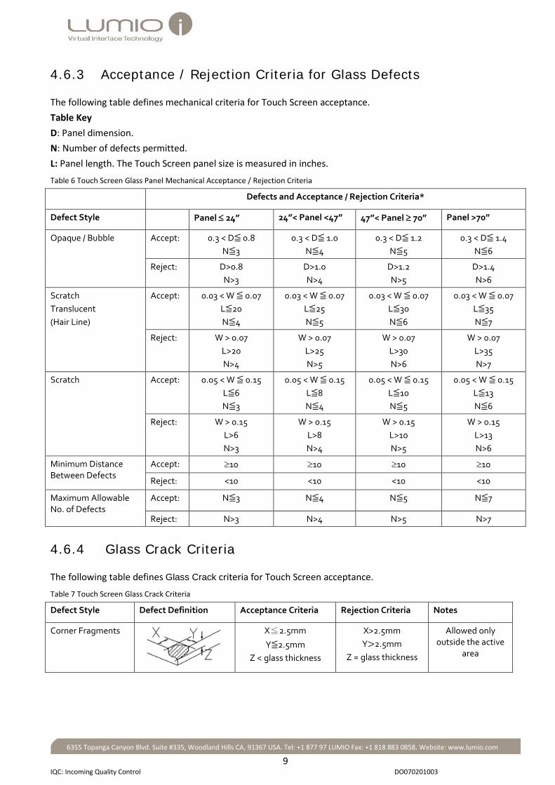
4.6.3 Acceptance / Rejection Criteria for Glass Defects
The following table defines mechanical criteria for Touch Screen acceptance. Table Key D: Panel dimension. N: Number of defects permitted. L: Panel length. The Touch Screen panel size is measured in inches.
Table 6 Touch Screen Glass Panel Mechanical Acceptance / Rejection Criteria
4.6.4 Glass Crack Criteria
The following table defines Glass Crack criteria for Touch Screen acceptance.
Table 7 Touch Screen Glass Crack Criteria
Defect Style Defect Definition Acceptance Criteria Rejection Criteria Notes
Corner Fragments
X≦2.5mm
Y≦2.5mm Z < glass thickness
X>2.5mm Y>2.5mm
Z = glass thickness
Allowed only outside the active
area
Defects and Acceptance / Rejection Criteria*
Defect Style Panel ≤ 24” 24”< Panel <47” 47”< Panel ≥ 70” Panel >70”
Opaque / Bubble Accept: 0.3 < D≦ 0.8 N≦3
0.3 < D≦ 1.0 N≦4
0.3 < D≦ 1.2 N≦5
0.3 < D≦ 1.4 N≦6
Reject: D>0.8 N>3
D>1.0 N>4
D>1.2 N>5
D>1.4 N>6
Scratch Translucent (Hair Line)
Accept: 0.03 < W ≦ 0.07 L≦20 N≦4
0.03 < W ≦ 0.07 L≦25 N≦5
0.03 < W ≦ 0.07 L≦30 N≦6
0.03 < W ≦ 0.07 L≦35 N≦7
Reject: W > 0.07 L>20 N>4
W > 0.07 L>25 N>5
W > 0.07 L>30 N>6
W > 0.07 L>35 N>7
Scratch
Accept: 0.05 < W ≦ 0.15 L≦6 N≦3
0.05 < W ≦ 0.15 L≦8 N≦4
0.05 < W ≦ 0.15 L≦10 N≦5
0.05 < W ≦ 0.15 L≦13 N≦6
Reject: W > 0.15 L>6 N>3
W > 0.15 L>8 N>4
W > 0.15 L>10 N>5
W > 0.15 L>13 N>6
Minimum Distance Between Defects
Accept: ≥10 ≥10 ≥10 ≥10
Reject: <10 <10 <10 <10
Maximum Allowable No. of Defects
Accept: N≦3 N≦4 N≦5 N≦7
Reject: N>3 N>4 N>5 N>7

10
IQC: Incoming Quality Control DO070201003
6355 Topanga Canyon Blvd. Suite #335, Woodland Hills CA, 91367 USA. Tel: +1 877 97 LUMIO Fax: +1 818 883 0858. Website: www.lumio.com
Defect Style Defect Definition Acceptance Criteria Rejection Criteria Notes
Side Fragments
X≦2.5mm
Y≦2.5mm Z < glass thickness
X>2.5mm Y>2.5mm
Z = glass thickness
Allowed only outside the active
area
Progressive Crack
N=0 N>0 Not Allowed
4.6.5 Glass Surface Flatness
Overview The Sensors and LED PCB’s are assembled on the Touch Screen glass panel. The sensors must detect the LED PCBs in their field of view. Therefore, glass flatness is essential in order to ensure that the sensors detect the LED PCB’s, and must be tested prior to Touch Screen assembly. The following table displays glass flatness requirements for panels.
Table 8 Glass Flatness for Panels
Glass size [inches] Glass Flatness Requirements for System Integration (mm)
Less than 27 1.0 mm
28 to 52 1.5 mm More than 52 2.0 mm
4.6.6 Glass Flatness Test
The glass flatness test establishes whether the glass meets glass flatness requirements. Assemble the components specified below, and perform the glass flatness test. The following diagram displays glass flatness test components.
Figure 3 Glass Flatness Test

11
IQC: Incoming Quality Control DO070201003
6355 Topanga Canyon Blvd. Suite #335, Woodland Hills CA, 91367 USA. Tel: +1 877 97 LUMIO Fax: +1 818 883 0858. Website: www.lumio.com
4.6.7 Glass Flatness Test Components
Prepare the following components for the glass flatness test.
Table 9 Glass Flatness Test Components
Component Description
A standard flat table The table must be as large as the glass / frame / overlay under test
Egg Foam The egg foam absorbs all table tolerances, and prevents the bending and distortion of the reference surface
Reference Surface The reference surface is a 10mm thick piece of glass with 0.2mm flatness, as large as the glass / frame / overlay under test. The reference surface can also be a polished granite block, the size of the glass / frame / overlay under test
Shim spacer Sheets or spacers of increasing thickness – 0.5 mm, 1 mm, 1.5 mm, 2 mm, 3 mm, 4 mm, 5 mm, 6 mm, 7 mm
Glass / Frame / Overlay under test
4.6.8 Glass Flatness Test Process
Assemble the test components as shown in Figure 3 Glass Flatness Test above.
To test glass flatness: 1. Place the glass / frame / overlay under test on top of the reference surface. 2. Insert the thinnest shim spacer between the glass / frame / overlay under test and the reference surface. 3. If the thinnest shim spacer can be inserted, insert the next sized shim spacer.
When a shim spacer cannot be inserted, glass flatness is established, that is the last shim spacer that was inserted between the glass / frame / overlay under test and the reference surface, represents the glass flatness.
4. Flip the glass / frame / overlay under test over and place it on top of the reference surface. 5. Repeat steps 2 -3 above in order to determine glass flatness of the flip side.
The glass flatness test passes if the results meet requirements specified in Glass Surface Flatness on page 10.
4.6.9 Placing Components on Glass
If the glass is not flat, but passes the test requirements, place the components (Such as sensors etc.) on the concave side of the glass.
To place the components on the concave side of the glass: 1. Compare the glass flatness test results for each side of the glass panel (To compare the glass flatness test
results see Glass Flatness Test Process above). The side of the glass with the best test flatness result is the concave side.
2. Place the components on the concave side of the glass.

12
Pre-Assembly: Assembling the Active Barrier DO070201003
6355 Topanga Canyon Blvd. Suite #335, Woodland Hills CA, 91367 USA. Tel: +1 877 97 LUMIO Fax: +1 818 883 0858. Website: www.lumio.com
Chapter 5 Pre-Assembly: Assembling the Active Barrier 5.1 Requirements
After inspecting and approving the incoming components, prepare the tools and materials required to assemble the Touch Screens (See Appendix E Tool and Materials on page 56) This section includes instructions for assembling the Active Barrier for the following systems:
• Assembling the Active Barrier for Dual Sensor Systems below • Assembling the Active Barrier for Quad Sensor Systems on page 17
5.2 Assembling the Active Barrier for Dual Sensor Systems
Dual Sensor systems include the following features:
• A Sensor is placed in each corner of the top side of the panel • There is only one long Rod Holder placed on the bottom side of the panel • The other long “Rod Holder” is a plastic bar used for decorative purposes only, which is placed on the top of
the panel • IR Rods and LED PCB wiring are not inserted into the Decorative Holder • A right angle LED (SMT) Corner Housing (hereafter: “Corner Housing”) is placed in each corner of the bottom
side of the panel.
The following diagram describes the Dual Sensor system layout.
Fig 5: Dual Sensor System Layout

13
Pre-Assembly: Assembling the Active Barrier DO070201003
6355 Topanga Canyon Blvd. Suite #335, Woodland Hills CA, 91367 USA. Tel: +1 877 97 LUMIO Fax: +1 818 883 0858. Website: www.lumio.com
The following picture displays the Dual Sensor system components.
Fig 6: Dual Sensor System Components
To assemble the Active Barrier for Dual Sensor Touch Screen systems: 1. Insert the IR Rods into the Rod Holders.
Note:
• IR Rod dimensions are supplied in the Crystal Touch Kit / Panel Content packing list
• The short IR Rods are inserted into the Rod Holders adjacent to the sensors and corners of the Active Barrier
• The short IR Rod adjacent to the sensor has a white painted end. The painted end faces the sensor
EXAMPLE: The following picture displays a cross section of a Rod Holder with IR Rods. Note that the short IR Rods are placed at the ends of the Rod Holder.
Figure 4 Rod Holder Cross Section
a. Insert a side IR Rod into the right angle LED (SMT) Corner Housing (hereafter: “Corner Housing”). Verify that the IR Rod is fully inserted into the Corner Housing, and that the flat side with the painted white line faces the outer side of the Corner Housing. The following pictures display the IR Rod inserted into the Corner Housing.
Figure 5 Side Rod - Corner Housing Insertion

14
Pre-Assembly: Assembling the Active Barrier DO070201003
6355 Topanga Canyon Blvd. Suite #335, Woodland Hills CA, 91367 USA. Tel: +1 877 97 LUMIO Fax: +1 818 883 0858. Website: www.lumio.com
The following diagram displays a cross-section of the IR Rod inserted into the Corner Housing.
Figure 6 Rod inserted into Corner Housing
b. Insert the side IR Rod into the side Rod Holder. Ensure that:
• The IR Rod is fully inserted and placed straight inside the Rod Holder • The Rod Holder fits into the Corner Housing
The following picture displays the colored end of the IR Rod.
Figure 7 Top End of Rod
The following picture displays insertion of the side IR Rod into the Rod Holder.
Figure 8 Inserting the Side Rod into the Holder
The following diagram displays a cross-section of the Side Rod Holder with an IR Rod, inserted into the Corner Housing.
Figure 9 Inserting the Side Rod into the Holder

15
Pre-Assembly: Assembling the Active Barrier DO070201003
6355 Topanga Canyon Blvd. Suite #335, Woodland Hills CA, 91367 USA. Tel: +1 877 97 LUMIO Fax: +1 818 883 0858. Website: www.lumio.com
2. Insert a Reflector on top of the IR Rod.
Note:
• Distance the Reflector 30 mm from the LED PCB’s • Do not distance the Reflector from sensors • As the Reflectors are distanced 30 mm away from the LED PCBs, they are correspondingly shorter than
the IR Rods that they are placed on (30 mm when the IR Rod is connected to one LED PCB, 60 mm when the IR Rod is connected to two LED PCBs, one at each end of the rod) The following picture displays a reflector being inserted into a Rod Holder.
Figure 10 Inserting a Reflector into a Rod Holder
3. Insert a Dummy LED PCB into the Rod Holder, immediately after the IR Rod. 4. Insert an IR Rod on the other side of the Dummy LED PCB. (Adjacent to the Dummy LED). 5. Insert a reflector on top of the second IR Rod.
The following picture displays a Dummy LED inserted in a Rod Holder between two IR Rods.
Figure 11 Dummy LED PCB
The following diagram displays a cross section of a Rod Holder with a Dummy LED PCB inserted into the Rod Holder, between two IR Rods.
Figure 12 Dummy LED PCB Cross Section
The following picture displays a cross section of IR Rods in a Rod Holder with reflectors and Dummy LED PCBs.

16
Pre-Assembly: Assembling the Active Barrier DO070201003
6355 Topanga Canyon Blvd. Suite #335, Woodland Hills CA, 91367 USA. Tel: +1 877 97 LUMIO Fax: +1 818 883 0858. Website: www.lumio.com
Figure 13 Rod Holder Cross Section
6. Remove the Dummy LED.
The following picture displays a cross section of an assembled Rod Holder (Without LED PCB wiring).
Figure 14 Assembled Rod Holder
7. Attach Tesa double sided tape to the side of the Rod Holder that will be attached to the glass.
Note: Ensure that the tape is attached to the Corner Housing as well as the Rod Holder.
The following picture displays tape attachment to the Rod Holder and Corner Housing.
Figure 15 Attaching Double Sided Tape to Rod Holder and Corner
8. Repeat steps 1 to 7 above for the second side Rod Holder and the long Bottom Rod Holder (As there are only two sensors, the top long holder is a decorative holder with no components). The following picture displays a Dual Sensor system panel ready for assembly.
Figure 16 Dual Sensor System Panel

17
Pre-Assembly: Assembling the Active Barrier DO070201003
6355 Topanga Canyon Blvd. Suite #335, Woodland Hills CA, 91367 USA. Tel: +1 877 97 LUMIO Fax: +1 818 883 0858. Website: www.lumio.com
5.3 Assembling the Active Barrier for Quad Sensor Systems
Quad Sensor systems include the following features:
• A sensor is attached to each corner of the panel • Unlike Dual Sensor systems, all sides of the panel contain IR Rods and LED PCB’s • There are no Corner Housings
The following diagram describes the Quad Sensor system layout
Fig 18: Quad Sensor System Layout
Quad Sensor system components are identical to Dual Sensor system components (See Assembling the Active Barrier for Dual Sensor Systems on page 12) but have 4 sensors and a Rod Holder including an IR Rod, Reflector and PCB LED wire instead of the Decorative Rod on the top side of the Active Barrier.
To assemble the Active Barrier for Quad Sensor systems The procedure for assembling the Active Barrier for Quad Sensor systems is identical to the procedure for assembling the Active Barrier for Dual Sensor systems (See Assembling the Active Barrier for Dual Sensor Systems on page 12) with changes due to the different systems as mentioned above.

18
Attaching the Active Barrier to the Touch Screen Glass Panel DO070201003
6355 Topanga Canyon Blvd. Suite #335, Woodland Hills CA, 91367 USA. Tel: +1 877 97 LUMIO Fax: +1 818 883 0858. Website: www.lumio.com
Chapter 6 Attaching the Active Barrier to the Touch Screen Glass Panel Attach the Active Barrier to the glass panel after assembling its components (To assemble the Active Barrier components, see Pre-Assembly: Assembling the Active Barrier on page 12). The procedure for attaching the Active Barrier to the glass panel in Dual and Quad Sensor systems is identical, except that Dual Sensor systems require only two sensors in the top corners of the glass panel, and the bottom corners of the glass panel have corner holders in place of sensors. Lumio provides a manual assembly kit designed to enhance Touch Screen panel assembly, in order to provide optimal Touch Screen performance. This section describes how to assemble Touch Screens on glass panels using the manual assembly kit. The following picture displays manual assembly kit components.
Fig 1: Manual Assembly Kit
The following table displays the manual assembly kit components.
Table 10 Manual Assembly Kit
Component Description Qty
Active Barrier corner holder The Active Barrier corner holder creates a frame for the Touch Screen Active Barrier, including a gap of 1 mm in the corners between the sensors and the Active Barrier
4
Sensor holder The sensor holder ensures precise positioning of the sensor on the Touch Screen glass panel, ensuring a gap of 1 mm between the sensors and the Active Barrier
1

19
Attaching the Active Barrier to the Touch Screen Glass Panel DO070201003
6355 Topanga Canyon Blvd. Suite #335, Woodland Hills CA, 91367 USA. Tel: +1 877 97 LUMIO Fax: +1 818 883 0858. Website: www.lumio.com
To attach the Active Barrier to the glass panel: 1. Draw lines on the glass panel representing the position of the Active Barrier on the glass panel.
Note:
• The lines’ specifications representing the Active Barrier’s dimensions are specified in the Crystal Touch Kit Panel Content packing list supplied by Lumio (x, y lx, ly dimensions)
• Draw the lines on the side of the glass panel that the Active Barrier is not attached to, as at the end of the process the drawing must be erased with alcohol
Fig 19: Active Barrier Dimensions on Glass Panel
2. Insert the Rod Holders into the Active Barrier Corner Holders, to form the Active Barrier.
Note:
• When inserting the Rod Holders, ensure that the clamps are open. Close the clamps after insertion to secure the Rod Holders.
• Detach a small part of the double sided tape before placing the Rod Holders and Rod Holder Corner Spacers on the glass pane, to enable tape removal
The following pictures display open and closed Corner Holders.
Fig 20.1: Corner Holders Fig 20.2: Corner Holder Clamp Positions

20
Attaching the Active Barrier to the Touch Screen Glass Panel DO070201003
6355 Topanga Canyon Blvd. Suite #335, Woodland Hills CA, 91367 USA. Tel: +1 877 97 LUMIO Fax: +1 818 883 0858. Website: www.lumio.com
The following pictures display Rod Holders being inserted into Corner Holders.
Fig 21.1: Rod Holders in Active Barrier Corner Holder –Top View Fig 21.2: Rod Holders in Active Barrier Corner Holder –Underside View
3. Place the Active Barrier, attached to the Corner Holders, on the glass panel.
Fig 22: Rod Holders and Rod Holder Corner Spacers on Glass Panel
4. Remove the double sided tape and press the Rod Holders to the glass panel.
Note: To prevent dirt and fingerprints on the glass, use 3M cleaning cloth to press the Rod Holders to the glass panel.
5. Remove the Corner Spacers. The Active Barrier is attached to the glass panel, and is ready to be wired.

21
LED PCB Wiring DO070201003
6355 Topanga Canyon Blvd. Suite #335, Woodland Hills CA, 91367 USA. Tel: +1 877 97 LUMIO Fax: +1 818 883 0858. Website: www.lumio.com
Chapter 7 LED PCB Wiring This section includes LED PCB wiring instructions for
• LED PCB wiring for Dual Sensor Systems below • LED Wiring for Quad Sensor systems on page 24
7.1 LED PCB wiring for Dual Sensor Systems
The following diagram displays LED Wiring for dual sensor systems without an extension PCB Controller.
Figure 17 LED Wiring for Dual Sensor Systems
The following picture displays the LED Wire. Note the connector at the end of the wire, which will connect to the LED Extension wire, and which is placed at the top left of the Touch Screen as displayed in Figure 17 LED Wiring for Dual Sensor Systems above.
Figure 18 LED Wiring

22
LED PCB Wiring DO070201003
6355 Topanga Canyon Blvd. Suite #335, Woodland Hills CA, 91367 USA. Tel: +1 877 97 LUMIO Fax: +1 818 883 0858. Website: www.lumio.com
To route the LED wire for dual sensor systems without an Extension PCB Controller:
1. Insert the LED PCBs: a. Insert a LED PCB into the left corner housing. b. Insert a LED PCB into the right corner housing.
Note: Ensure that:
• The LED PCB is fully inserted into the Holders and is straight
• The LED Wire extension cable connector is positioned on the top left side of the panel
Figure 19 Led Wiring – Corner Housing
2. Route the LED PCB wire from the upper left corner to the bottom left corner, inserting LED PCBs in place of the dummy LEDs.
Figure 20 LED Wiring

23
LED PCB Wiring DO070201003
6355 Topanga Canyon Blvd. Suite #335, Woodland Hills CA, 91367 USA. Tel: +1 877 97 LUMIO Fax: +1 818 883 0858. Website: www.lumio.com
3. Cross over the Sensor to the next LED PCB. Figure 21 LED Corner Wiring
4. Insert the LED wire into the Rod Holder. Spread the excess wire along the Rod Holder.
5. Rout the LED wire around the Active Barrier by repeating steps 2 – 4 above, until wiring is completed.
Figure 22 LED Wire Insertion into Rod Holder
6. Assemble the rear covers on the Rod Holders, ensuring they are inserted firmly all along the Rod Holders.
Figure 23 Rear Cover Assembly
7. Connect the LED Wire to the JP3 connector on the PCB Controller using a LED Wire Power extension cable.
Note: The length of the cable enables the integrator to place the PCB Controller according to requirements.
Figure 24 LED Wire - PCB Controller Connection

24
LED PCB Wiring DO070201003
6355 Topanga Canyon Blvd. Suite #335, Woodland Hills CA, 91367 USA. Tel: +1 877 97 LUMIO Fax: +1 818 883 0858. Website: www.lumio.com
7.2 LED Wiring for Quad Sensor systems
Quad Sensor systems include/exclude PCB Controllers, depending on system size. This section includes:
• LED Wiring for Quad Sensor Systems without an Extension PCB Controller below • LED Wiring for Quad Sensor Systems with an Extension PCB Controller on page 25
7.3 LED Wiring for Quad Sensor Systems without an Extension PCB Controller
Wire systems without an Extension PCB Controller for quad system Touch Screens including less than 16 LEDPCBs. The following diagram displays LED Wiring for quad sensor systems without an extension PCB Controller. Figure 25 LED Wiring for Dual Sensor Systems
To route the LED Wire for quad sensor systems without an Extension PCB Controller: Routing the LED Wire for quad sensor systems that do not have PCB Controllers is identical to routing the LED Wire for Dual Sensor systems (See LED PCB wiring for Dual Sensor Systems on page 21), except that there are no Corner Housings. Rout the LED Wire in the direction displayed in Figure 25 above.

25
LED PCB Wiring DO070201003
6355 Topanga Canyon Blvd. Suite #335, Woodland Hills CA, 91367 USA. Tel: +1 877 97 LUMIO Fax: +1 818 883 0858. Website: www.lumio.com
7.4 LED Wiring for Quad Sensor Systems with an Extension PCB Controller
Wire systems with an Extension PCB Controller for quad system Touch Screens including more than 16 LEDPCBs. The following diagram displays LED wiring for a quad sensor system.
Figure 26 LED Wiring for a Quad Sensor System including an Extension PCB Controller
To route the LED Wire for quad sensor systems with an Extension PCB Controller: Routing the LED Wire for quad sensor systems with an Extension PCB Controller is identical to routing the LED Wire for Dual Sensor systems (See LED PCB wiring for Dual Sensor Systems on page 21) with the following exceptions: • There are no Corner Housings • There are two LED Wires. Rout the LED Wires as displayed in Figure 26 above
Note: The LED Wires are marked Left and Right to facilitate identification

26
Attaching Sensors to the Touch Screen Glass Panel DO070201003
6355 Topanga Canyon Blvd. Suite #335, Woodland Hills CA, 91367 USA. Tel: +1 877 97 LUMIO Fax: +1 818 883 0858. Website: www.lumio.com
Chapter 8 Attaching Sensors to the Touch Screen Glass Panel After wiring the Active Barrier, attach the sensors to the Touch Screen glass panel. A 1 mm gap between the sensors and the Rod Holders must be formed when attaching the sensors to the glass panel in order to prevent Rod Holders putting pressure on the sensors, causing them to move. Dedicated Corner Holders ensure that the sensors are correctly placed on the glass panel and that the 1mm gap is created. The sensors can be attached to the glass panel in the following manners: • By default, glue the sensors to the glass panel with Dymax 3069 epoxy, curing the glue with a UV machine • Only if it is not possible to use a UV machine (for example when the UV machine has no access to the
underside of the glass panel) glue the sensor to the glass panel with DP105 epoxy
Note: All procedures in this section apply to both Jenoptic and 2KC sensors.
The following picture displays a Corner Holder, used for attaching sensors to the glass panel.
Figure 27 Sensor Corner Holder
This section includes: • Attaching Sensors to the Glass Panel with Dymax 3069 Epoxy on page 27 • Attaching Sensors to the Glass Panel with DP 105 Epoxy on page 31

27
Attaching Sensors to the Touch Screen Glass Panel DO070201003
6355 Topanga Canyon Blvd. Suite #335, Woodland Hills CA, 91367 USA. Tel: +1 877 97 LUMIO Fax: +1 818 883 0858. Website: www.lumio.com
8.1 Attaching Sensors to the Glass Panel with Dymax 3069 Epoxy
The following section describes how to attach sensors to glass panels with Dymax 3069 epoxy.
To attach sensors to the glass panel with Dymax epoxy: 1. Insert the screw into the Sensor Holder.
Note: Ensure that the screw does not protrude from the Sensor Holder.
Figure 28 Inserting a Screw into the Sensor Holder
2. Place a sensor on the Sensor Holder.
Figure 29 Sensor placed on Sensor Holder

28
Attaching Sensors to the Touch Screen Glass Panel DO070201003
6355 Topanga Canyon Blvd. Suite #335, Woodland Hills CA, 91367 USA. Tel: +1 877 97 LUMIO Fax: +1 818 883 0858. Website: www.lumio.com
3. Attach an FFC cable to the sensor and place the sensor on the glass panel.
Figure 30 Sensor on Glass Panel
4. Test the sensor signal and boundaries:
Note: Perform a sensor signal and boundary test in order to ensure sensor signal reception.
a. Connect the sensor to the PCB Controller with a flat (FCC) cable. b. Connect the PCB Controller to a PC. c. Install Crystal Touch Manager (To install Crystal Touch Manager, see Appendix B: Installing Crystal Touch
Manager d. on page 49). e. Perform a scope signal and boundary test (To perform a scope signal and boundary test, see the Crystal
Touch Manager User Guide), adjusting the sensor position on the glass panel until the optimal signal and boundaries are obtained).
5. Glue the sensor to the glass panel with Dymax 3069:
a. Soak a cotton Q Tip swab in acetone and clean the area on the glass intended for attaching the sensor.
Warning: Ensure that the acetone does not come into contact with the Rod Holders or any other Active Barrier components.
Figure 31 Clean Glass with Acetone

29
Attaching Sensors to the Touch Screen Glass Panel DO070201003
6355 Topanga Canyon Blvd. Suite #335, Woodland Hills CA, 91367 USA. Tel: +1 877 97 LUMIO Fax: +1 818 883 0858. Website: www.lumio.com
b. Clean the Sensor with alcohol.
Figure 32 Cleaning the Sensor
c. Attach a drop of Dymax 3069 adhesive to the sensor:
i. Prepare the necessary tools and materials.
Table 11 Tools and Materials
Tool Description and Part Number
Figure 33 Dymax 3069 Dispenser
Figure 34 Dispense: 450 gauge – Purple Tip
P/N TE721050B45
Figure 35 Dispense tip: TE 21 Gauge - Purple
P/N OKI 921050-TE or OEM TE7105
Figure 36 Dispense: 450 gauge – Yellow Tip
ii. Attach a needle tip to the Dymax dispenser.
Figure 37 Needle attached to Dymax Dispenser

30
Attaching Sensors to the Touch Screen Glass Panel DO070201003
6355 Topanga Canyon Blvd. Suite #335, Woodland Hills CA, 91367 USA. Tel: +1 877 97 LUMIO Fax: +1 818 883 0858. Website: www.lumio.com
iii. Attach a drop of Dymax 3069 epoxy onto the underside center of the sensor.
Figure 38 Attaching Dymax Adhesive to Glass
iv. Attach the Sensor (still connected to the Corner Holder) to the glass panel
Figure 39 Attaching Sensor to Glass Panel
d. Test sensor signal and boundaries (To test boundaries, see step 4 above).
Note: Fine Tuning: If necessary, adjust the sensor position manually to achieve the optimal signal and boundaries.
e. Cure the Dymax adhesive with a portable UV machine:
I. Place the UV machine directly under the glass panel where the sensor is placed. II. Activate the UV machine to cure the epoxy.
Note: For UV curing time, see Glue Curing Time on page 48.

31
Attaching Sensors to the Touch Screen Glass Panel DO070201003
6355 Topanga Canyon Blvd. Suite #335, Woodland Hills CA, 91367 USA. Tel: +1 877 97 LUMIO Fax: +1 818 883 0858. Website: www.lumio.com
Figure 40 Curing Adhesive with an UV Machine
6. Turn the screw clockwise to release the Sensor Holder.
The sensor is fixed to the glass panel and a 1 mm gap between the sensors and the Rod Holders is created.
7. Test sensor signal and boundaries (To test boundaries, see step 4 above).
8. Repeat steps 2 – 7 above for all sensors.
The sensors are attached to the glass panel.
8.2 Attaching Sensors to the Glass Panel with DP 105 Epoxy
The following section describes how to attach sensors to glass panels with 3M DP 105 epoxy.
Note: Use DP 105 epoxy to attach sensors to the glass panel only when it is not possible to attach the sensors with Dymax epoxy due to constrictions preventing the use of the UV machine (For example, when the UV machine cannot gain access to the underside of the glass panel).
To attach sensors to the glass panel with DP 105 epoxy:
1. Repeat steps 1-4 of the procedure described in Attaching Sensors to the Glass Panel with Dymax 3069 Epoxy on page 27.
2. Glue the sensor to the glass panel with Dymax 3069:
a. Attach the Soak a cotton Q Tip swab in acetone and clean the area on the glass intended for attaching the sensor (Seeon page 28 on page 28)
b. Clean the Sensor with alcohol (See Figure 32 Cleaning the Sensor on page 29).
c. Attach a drop of DP 105 epoxy to the sensor:
i. Prepare the adhesive tools and materials necessary to attach the sensor to the glass panel.

32
Attaching Sensors to the Touch Screen Glass Panel DO070201003
6355 Topanga Canyon Blvd. Suite #335, Woodland Hills CA, 91367 USA. Tel: +1 877 97 LUMIO Fax: +1 818 883 0858. Website: www.lumio.com
Table 12 Adhedsive Tools and Materials
Tool Description and Part Number
Figure 41 3M EPX Plus II Applicator
P/N 62-9170-9930
Figure 42 Sealing glue: 3M Epoxy glue DP105
P/N 62-3287-3830-7-3
ii. Prepare the DP105 epoxy.
Table 13 Preparing the DP 105 Adhesive
A. Clean all accumulated lumps of glue, and squeeze the applicator to ensure that the glue flows smoothly and evenly from both nozzles onto a pre-prepared surface.
Figure 43 Removing lumps of glue
B. Mix the epoxy on the surface with a toothpick or similar instrument, until the glue from both nozzles form an uniform glue.
Figure 44 Mixing the epoxy
Note: For further information concerning DP 105 glue, see http://www.lumio.com/outgoing/Documentation/Assembly_guides/3M DP-105 Clear.pdf.
iii. Place a drop of epoxy and spread evenly on the underside center of the sensor.

33
Attaching Sensors to the Touch Screen Glass Panel DO070201003
6355 Topanga Canyon Blvd. Suite #335, Woodland Hills CA, 91367 USA. Tel: +1 877 97 LUMIO Fax: +1 818 883 0858. Website: www.lumio.com
Figure 45 Spreading the Epoxy on the Sensor
iv. Attach the Sensor (still connected to the Corner Holder) to the glass panel (See Figure 39 Attaching Sensor to Glass Panel on page 30).
d. Test sensor signal and boundaries (To test sensor signal and boundaries, see step 4 of Attaching Sensors to the Glass Panel with Dymax 3069 Epoxy on page 27).
3. Turn the screw clockwise to release the Sensor Holder. The sensor is fixed to the glass panel and a 1 mm gap between the sensors and the Rod Holders is created.
4. Test sensor signal and boundaries (To test boundaries, see step 4 above). 5. Repeat steps 2 – 4 above for all sensors.
The sensors are attached to the glass panel.

34
Connecting the Sensors to the PCB Controller DO070201003
6355 Topanga Canyon Blvd. Suite #335, Woodland Hills CA, 91367 USA. Tel: +1 877 97 LUMIO Fax: +1 818 883 0858. Website: www.lumio.com
Chapter 9 Connecting the Sensors to the PCB Controller After placing the sensors on the glass panel, connect the sensors to the PCB Controller with FFC (flat) cables. Two types of sensors are available, Jenoptic sensors and 2 KC sensors. This section includes:
• Connecting Jenoptic Sensors below • Connecting 2 KC Sensors on page 36
9.1 Connecting Jenoptic Sensors
Connect Jenoptic sensors to the PCB Controller with 1 mm FFC cables.
To connect the Jenoptic sensors to the PCB Controller: 1. Connect the FFC (flat) cables to the Sensors.
Note: Ensure that the flat cable’s contacts face down and that the blue strip of tape on the cable faces up.
Figure 46 Connecting a Sensor to a Flat Cable
2. Connect the FFC (flat) cables to the connectors on the PCB Controller board as follows (The following numbering is displayed on the PCB Controller board): Dual Sensor Systems Left Top (LT) sensor J1 Right Top (RT) sensor J2 Quad Sensor Systems Left Top (LT) sensor J1 Right Top (RT) sensor J2 Left Bottom (LB) sensor J3 Right Bottom (RB) sensor J4
The following pictures display connectors for FFC cables on the PCB Controller board.

35
Connecting the Sensors to the PCB Controller DO070201003
6355 Topanga Canyon Blvd. Suite #335, Woodland Hills CA, 91367 USA. Tel: +1 877 97 LUMIO Fax: +1 818 883 0858. Website: www.lumio.com
Figure 47 PCB Controller Connections
Figure 48 Connecting a Sensor to the PCB Controller

36
Connecting the Sensors to the PCB Controller DO070201003
6355 Topanga Canyon Blvd. Suite #335, Woodland Hills CA, 91367 USA. Tel: +1 877 97 LUMIO Fax: +1 818 883 0858. Website: www.lumio.com
9.2 Connecting 2 KC Sensors
2 KC sensors are equipped with a 0.5 mm flat (FFC) cable (Hereafter: “Flat Cable”). PCB Controllers include 2 types of flat cable connectors for 2 KC sensors wiring, 0.5 mm connectors and 1 mm connectors. Therefore, 2 KC sensors are wired to PCB Controllers with a flat cable in the following ways, depending on the type of PCB Controller connector:
• Direct connection: The sensor is wired directly to the PCB Controller (including a 0.5 mm connector) with a 0.5 mm flat cable
• Connection via a flat cable adaptor: The sensor is wired to the PCB Controller (including a0.5 mm connector) with a cable adaptor
The following components are provided for 2 KC sensor - PCB Controller connectivity.
Table 14 2 KC sensor -flat cable Connectivity Components in a Quad Sensor System2 KC sensor -flat cable Connectivity Components in a Quad Sensor System
Component Number of Components 2 KC sensor 4
0.5 mm flat (FFC) cable 4
1 mm flat (FFC) cable 4 Cable adaptor 4 PCB Controller 1
Note: Insert flat cables into connectors as displayed in the following pictures, in order to prevent sensor signal distortion or broken connector locks.
Figure 49 Inserting Flat Cables into Connectors
IMPORTANT: When inserting the flat cable into the connector, insert the blue strip of the cable fully into the sensor connector.
This section includes: • Direct 2 KC Sensor - PCB Controller Connection on page 37 • Connecting a 2 KC Sensor to a PCB Controller with a Flat Cable Adaptor on page 38

37
Connecting the Sensors to the PCB Controller DO070201003
6355 Topanga Canyon Blvd. Suite #335, Woodland Hills CA, 91367 USA. Tel: +1 877 97 LUMIO Fax: +1 818 883 0858. Website: www.lumio.com
9.2.1 Direct 2 KC Sensor - PCB Controller Connection
The 2 KC sensor is wired directly to the PCB Controller when the PCB Controller is equipped with a 0.5 mm flat cable connector. The following diagram displays direct 2 KC sensor - PCB Controller connectivity.
Figure 50 Direct 2 KC sensor - PCB Controller Connectivity
To wire the 2 KC sensor directly to the PCB Controller: 1. Connect the 2 KC sensor to the 0.5 mm flat cable.
Note:
• Fold and attach the flat cable as close to the sensor connector as possible • Do not fold the blue connector found at the end of the cable more than once, as folding the blue
connector may cause damage to the cable’s contacts - Click the following link to view how to fold the blue connector: http://www.lumio.com/outgoing/Documentation/Video/Folding_ffc_blue_connector.mp4
• If the distance between the bezel and the Active Barrier is no larger than 0.5 mm, the flat cable can be folded as displayed in the diagrams and picture below, in order to accommodate different systems.
The following diagram and pictures display 2 KC sensor – FFC cable wiring.
Figure 51 Flat (FFC) Cable - Sensor Connection
2. Connect the other end of the 0.5 mm flat cable to the PCB Controller.

38
Connecting the Sensors to the PCB Controller DO070201003
6355 Topanga Canyon Blvd. Suite #335, Woodland Hills CA, 91367 USA. Tel: +1 877 97 LUMIO Fax: +1 818 883 0858. Website: www.lumio.com
Figure 52 PCB Controller - Flat Cable Connection
9.2.2 Connecting a 2 KC Sensor to a PCB Controller with a Flat Cable Adaptor
The 2 KC sensor is equipped with a 0.5 mm flat cable. The 2 KC sensor is wired to the PCB Controller with a cable adaptor when the PCB Controller is equipped with a 1 mm flat cable connector, necessitating cable adaptation. 2 KC sensor- PCB Controller with a flat cable adaptor includes:
• Connecting the 2 KC Sensor to a flat cable adaptor • Connecting the PCB Controller to a flat cable adaptor
The following diagram displays 2 KC sensor - PCB Controller connectivity with a flat cable adaptor.
Figure 53 PCB Controller Connectivity with a Flat Cable Adaptor
To connect the 2 KC sensor to the PCB Connector: 1. Connect one end of the 0.5 mm flat cable to the 2 KC sensor (To connect the 0.5 mm flat cable to the 2 KC
sensor see Direct 2 KC Sensor - PCB Controller Connection on page 37). 2. Connect the other end of the 0.5 mm flat cable to the cable adaptor.

39
Connecting the Sensors to the PCB Controller DO070201003
6355 Topanga Canyon Blvd. Suite #335, Woodland Hills CA, 91367 USA. Tel: +1 877 97 LUMIO Fax: +1 818 883 0858. Website: www.lumio.com
Figure 54 : Cable Adaptor - 0.5 mm Flat Cable Connection
3. Connect the PCB Controller to the cable adaptor with a 1 mm flat cable.
Figure 55 Cable Adaptor - 1 mm Flat Cable Connection
4. Connect the other end of the 1 mm flat cable to the PCB Controller.
Figure 56 : PCB Controller - 1 mm Flat Cable Connection

40
Connecting the PCB Controller to the Extension PCB Controller DO070201003
6355 Topanga Canyon Blvd. Suite #335, Woodland Hills CA, 91367 USA. Tel: +1 877 97 LUMIO Fax: +1 818 883 0858. Website: www.lumio.com
Chapter 10 Connecting the PCB Controller to the Extension PCB Controller Quad Sensor systems including more than 16 LED PCBs require an Extension PCB Controller to power-up the system. The PCB Controller is connected to an Extension PCB Controller with a LED Power Control wire bundle, including two LED Control Extension wire connectors and two USB power supply extension wire connectors. The following figure displays an Extension PCB Controller.
Figure 57 Extension PCB Controller Front View Figure 58 Extension PCB Rear View
The following figure displays a LED Power Control wire bundle.
Figure 59 LED Power Control Wire Bundle

41
Connecting the PCB Controller to the Extension PCB Controller DO070201003
6355 Topanga Canyon Blvd. Suite #335, Woodland Hills CA, 91367 USA. Tel: +1 877 97 LUMIO Fax: +1 818 883 0858. Website: www.lumio.com
To connect the PCB Controller to the Extension PCB Controller 1. Connect one end of the LED Power Control wire to the JP3 connector on the PCB Controller board. 2. Connect the other end of the LED Power Control wire to the JP3 connector on the Extension PCB
Controller board. 3. Connect one end of the USB Power Supply extension wire to the J5 connector on the PCB Controller
board. 4. Connect the other end of the USB Power Supply extension wire to the J1 connector on the PCB
Controller board. The following picture displays a PCB Controller connected to an Extension PCB Controller.
Figure 60 PCB Controller connected to an Extension PCB Controller

42
Distribution Ready Procedure DO070201003
6355 Topanga Canyon Blvd. Suite #335, Woodland Hills CA, 91367 USA. Tel: +1 877 97 LUMIO Fax: +1 818 883 0858. Website: www.lumio.com
Chapter 11 Distribution Ready Procedure After assembling the Touch Screen, perform the Distribution Ready Procedure with the Lumio Production Wizard application. The Distribution Ready Procedure includes: • Testing: Testing ensures that the Crystal TouchTM panel is assembled correctly, that all the sensors have
the correct field of view and are level, that all connectors are functioning properly, and that the correct firmware is loaded on the Controller
• Calibration: Calibration fine-tunes the sensors to ensure that they accurately detect the co-ordinates when Users touch the Crystal TouchTM panel
• Configuration: Configuration updates the settings on the Controller to suit the type of Crystal TouchTM panel and the customer’s requirements
To perform the Distribution Ready Procedure with the Lumio Production Wizard application, see the Lumio Production Wizard v6.9 User Guide: http://www.lumio.com/outgoing/Documentation/Production_Wizard/Production_Wizard_User_Guide_v6.9_A0.pdf).
Chapter 12 OQC Outgoing Quality Control Prior to packing and shipping, perform the following OQC inspection for assembled Lumio Touch Screen panels.
NOTE: Touch Screen performance is not tested as part of the OQC process, as the test is performed by the Production Wizard as part of the Distribution Ready Procedure.
This section includes: • Glass Inspection below • Components Inspection on page 44 • Touch Screen Dimension Verification on page 45
12.1 Glass Inspection
The outgoing glass inspection includes the following sections: • Cleaning below • Mechanical Criteria on page 43 • Glass Crack Criteria on page 44
12.2 Cleaning
Clean the glass panels according to the following criteria:
• Remove finger prints and other foreign materials • Clean the glass panel with a Microfiber cloth (Such as 3M Essential Microfiber Cloth ref: 2012) • Ensure that adhesive material such as glue or tape, do not intrude into the Active Barrier • Clean the Touch Screen glass panel with the following cleaning agents of any respectable manufacturer: • Isopropyl 99%
43
OQC Outgoing Quality Control DO070201003
6355 Topanga Canyon Blvd. Suite #335, Woodland Hills CA, 91367 USA. Tel: +1 877 97 LUMIO Fax: +1 818 883 0858. Website: www.lumio.com
• Isopropanol –IPA Note: For more information concerning the cleaning agents, their properties, usage, safety and so on, see:
• http://www.lumio.com/outgoing/Documentation/Cleaning_Materials/Isopropyl_99%_msds.pdf • http://www.lumio.com/outgoing/Documentation/Cleaning_Materials/Isopropanol_mads.pdf
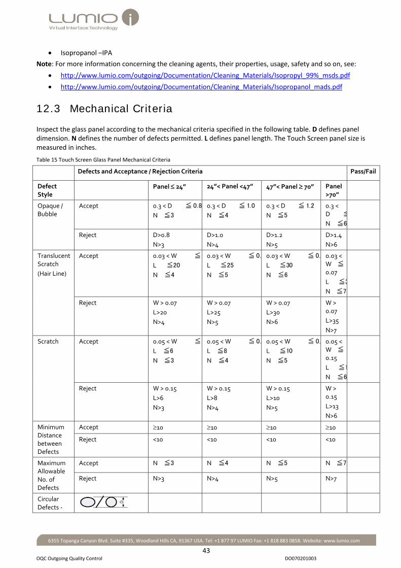
12.3 Mechanical Criteria
Inspect the glass panel according to the mechanical criteria specified in the following table. D defines panel dimension. N defines the number of defects permitted. L defines panel length. The Touch Screen panel size is measured in inches.
Table 15 Touch Screen Glass Panel Mechanical Criteria
Defects and Acceptance / Rejection Criteria Pass/Fail
Defect Style
Panel ≤ 24” 24”< Panel <47” 47”< Panel ≥ 70” Panel >70”
Opaque / Bubble
Accept 0.3 < D ≦ 0.8 N ≦3
0.3 < D ≦ 1.0 N ≦4
0.3 < D ≦ 1.2 N ≦5
0.3 < D ≦ N ≦6
Reject D>0.8 N>3
D>1.0 N>4
D>1.2 N>5
D>1.4 N>6
Translucent Scratch (Hair Line)
Accept 0.03 < W ≦ L ≦20 N ≦4
0.03 < W ≦ 0. L ≦25 N ≦5
0.03 < W ≦ 0. L ≦30 N ≦6
0.03 < W ≦ 0.07 L ≦3 N ≦7
Reject W > 0.07 L>20 N>4
W > 0.07 L>25 N>5
W > 0.07 L>30 N>6
W > 0.07 L>35 N>7
Scratch Accept 0.05 < W ≦ L ≦6 N ≦3
0.05 < W ≦ 0. L ≦8 N ≦4
0.05 < W ≦ 0. L ≦10 N ≦5
0.05 < W ≦ 0.15 L ≦1 N ≦6
Reject W > 0.15 L>6 N>3
W > 0.15 L>8 N>4
W > 0.15 L>10 N>5
W > 0.15 L>13 N>6
Minimum Distance between Defects
Accept ≥10 ≥10 ≥10 ≥10
Reject <10 <10 <10 <10
Maximum Allowable No. of Defects
Accept N ≦3 N ≦4 N ≦5 N ≦7
Reject N>3 N>4 N>5 N>7
Circular Defects -

44
OQC Outgoing Quality Control DO070201003
6355 Topanga Canyon Blvd. Suite #335, Woodland Hills CA, 91367 USA. Tel: +1 877 97 LUMIO Fax: +1 818 883 0858. Website: www.lumio.com
12.4 Glass Crack Criteria
Inspect the glass panel for cracks according to the criteria defined in the following table.
Table 16 Touch Screen Glass Crack Criteria
Defect Style Defect Definition Acceptance Criteria
Rejection Criteria
Notes Pass/Fail
Corner Fragments
X≦2.5mm
Y≦2.5mm Z < glass thickness
X>2.5mm Y>2.5mm Z = glass thickness
Allowed only outside the active area
Side Fragments
X≦2.5mm
Y≦2.5mm Z < glass thickness
X>2.5mm Y>2.5mm Z = glass thickness
Allowed only outside the active area
Progressive Crack
N=0 N>0 Not Allowed
12.5 Components Inspection
Perform the following OQC for the Touch Screen components.
Table 17 Components Inspection
Component Inspection Pass (OK) / Fail
Check PCB Controller P/N
PCB Controller –FFC connectivity – attach flat cables to corresponding connectors on the PCB Controller
LED wire routing – ends top left corner
LED Power cable routing and connectivity
5v Power supply
USB cable
Rod Holders attached to panel with double-sided Tesa tape
Sensors attached to panel with adhesive
3M Vinyl Electrical tape sealing Rod Holders
Cover Holders Placement on Rod Holders
LED wire cable installation Cosmetic QC for Active Barrier
Linear Defects -

45
OQC Outgoing Quality Control DO070201003
6355 Topanga Canyon Blvd. Suite #335, Woodland Hills CA, 91367 USA. Tel: +1 877 97 LUMIO Fax: +1 818 883 0858. Website: www.lumio.com
Component Inspection Pass (OK) / Fail Cosmetic QC for sealing adhesive
Installed software supplied by Lumio
IP 65 (waterproofing)
Touch Screen Packing
12.6 Touch Screen Dimension Verification
Verify the following Touch Screen dimensions as displayed in the following diagram: • Open Bezel width • Open Bezel width • The gap between the sensor and the Rod Holder • The gap between the Active Barrier and the top/bottom sides of the glass • The gap between the Active Barrier and the glass edge on the sides of the glass
Figure 61 OQC Touch Screen Dimension Verification
Note:
• C: The open bezel width • E: The open bezel height • J:The gap between the sensor and the Rod Holder • L: The gap between the Active Barrier and the top/bottom sides of the glass • G: The gap between the Active Barrier and the glass edge on the sides of the glass
The dimensions are tested on several points on the screen (C1, C2 and so on for width, E1, E2 and so on for height, J1, J2 and so on for the gap between the sensor and the Rod Holders. The acceptance / rejection criteria for the dimensions are displayed in the diagram above)

46
Appendix A: Sensor Adhesion Requirements DO070201003
6355 Topanga Canyon Blvd. Suite #335, Woodland Hills CA, 91367 USA. Tel: +1 877 97 LUMIO Fax: +1 818 883 0858. Website: www.lumio.com
Chapter 13 Appendix A: Sensor Adhesion Requirements This section describes the requirements, the tools, and the types of adhesives for gluing sensors on Touch Screen panels. This section includes:
• Sensor Adhesion Requirements below • Primers below • Types of Adhesives on page 47 • Adhesive Curing Requirements on page 48
13.1 Sensor Adhesion Requirements
Sensor adhesion is subject to the following requirements.
Table 18 Sensor Adhesion Requirements
Adhesive Environment Adhesive Requirement
Sensor Adhesion in a non-coated Glass Environment UV Dymax 3069
Sensor Adhesion on Metal Frames DP105
Enhancing Glue for Indoor Applications For Touch Screens larger than 50”: Enhancing glue for indoor applications is required. The glue type is DP105. For Touch Screens smaller than 50”: No enhancing glue for indoor applications is required.
Enhancing Glue for Outdoor Applications All outdoor applications: Epoxy Master Bond EP30R
Gluing Sensors on non – coated glass Do not glue sensors to a coated layer of glass, as they do not bond well on coated glass, and detach easily. If the glass is coated, remove or polish the gluing area to remove the coating. The strength of glass coating depends on coating types and coating processes.
Gluing sensors on Touch Screen panels in a non - IP65 Environment
Create a one millimeter gap between the sensors and the Rod Holders in a non - IP65 application environment.
13.2 Primers
The following requirements apply when applying primers. • Apply Primer 3901 (3M) before using all types of epoxy glues (DP105, EP30R). • Clean the Touch Screen panel glass with acetone, and polish, before applying primer.

47
Appendix A: Sensor Adhesion Requirements DO070201003
6355 Topanga Canyon Blvd. Suite #335, Woodland Hills CA, 91367 USA. Tel: +1 877 97 LUMIO Fax: +1 818 883 0858. Website: www.lumio.com
13.3 Types of Adhesives
The following table describes the types of adhesives used to glue sensors to Touch Screens in different environments.
Table 19 Adhesive Types in Different Environments
Adhesive Types
Substrate Assembly Method
Application Location
Screen Size
Glue Location Glue Type
1 Glass Adjustable Assembly Jig Manual Assembly (UV light access)
Indoor Small UV glue below the sensors
Dymax 3069
2 Glass Adjustable Assembly Jig Manual Assembly (UV light access)
Indoor Large UV glue below the sensors Epoxy glue on the sensor’s sides
Dymax 3069 Master bond EP30R
3 Glass Adjustable Assembly Jig Manual Assembly (UV light access)
Outdoor All Sizes
UV glue below the sensors Epoxy glue on the sensor’s sides
Dymax 3069 Master bond EP30R
4 Glass Manual Assembly No UV light access
Indoor All Sizes
UV glue below the sensors Epoxy glue on the sensor’s sides
DP105 DP105

48
Appendix A: Sensor Adhesion Requirements DO070201003
6355 Topanga Canyon Blvd. Suite #335, Woodland Hills CA, 91367 USA. Tel: +1 877 97 LUMIO Fax: +1 818 883 0858. Website: www.lumio.com
5 Glass Manual Assembly No UV light access
Outdoor All Sizes
Epoxy glue below the sensors Epoxy glue on the sensor’s sides
DP105 Master bond EP30R
6 Metal All Assembly Methods
All locations Small Epoxy glue below the sensors
DP105
7 Metal All Assembly Methods
All locations Large Epoxy glue below the sensors Epoxy glue on the sensor’s sides
DP105 DP105
13.4 Adhesive Curing Requirements
13.4.1 Glue Curing Tool Power Density
The following glue curing power densities apply: • The minimum glue curing tool power density in a non - glass substrate environment is 400mW/cm2. • The minimum glue curing tool power density measured after passing through a glass substrate is
120mW/cm2 (If the glue curing power density is lower than this value, use DP105 epoxy to glue sensors to panels).
13.4.2 Glue Curing Time
The UV glue curing time for a curing tool with a power density of 400mW/cm2 is as follows: • 30 sec for 2 mm glass • 60 sec for 3-8 mm glass • 120 sec for 10 - 12mm glass.
13.4.3 Lumio UV Glue Curing Tool
The Lumio UV glue curing tool for manual Touch Screen panel assembly enables fast and easy sensor adhesion to the Touch Screen panel. The minimum Lumio UV tool glue curing power density is 400mW/cm2.

49
Appendix B: Installing Crystal Touch Manager DO070201003
6355 Topanga Canyon Blvd. Suite #335, Woodland Hills CA, 91367 USA. Tel: +1 877 97 LUMIO Fax: +1 818 883 0858. Website: www.lumio.com
Chapter 14 Appendix B: Installing Crystal Touch Manager This appendix describes how to:
• Install Crystal Touch Manager • Solve permissions issues for Vista or Win 7 OS
The following Quick Start guides contains instructions for installing the Lumio Crystal Touch Manager Technician application. For comprehensive Crystal Touch Manager application installation instructions, see the Crystal Touch Manager User Guide.
14.1 Installing Crystal Touch Manager
To install Crystal Touch Manager: 1. Insert the Crystal Touch Manager CD received from Lumio.
The Crystal Touch Manager File Folder opens. 2. Select the Crystal Touch Manager exe.file.
The Crystal Touch Manager Setup Wizard opens. 3. Follow the Setup Wizard instructions to install Crystal Touch Manager.
14.2 Resolving Permission Issues for Vista and Win 7 OS
Resolve digitizer issues for Win Vista and Win 7 in the following ways: 1. Ensure that the Microsoft Touch functions are enabled:
a Navigate to Start > Control Panel > Pen and Touch. The Pen and Touch window opens.
b Select the Touch tab. c The Touch Pane opens. d Use your finger as an input device and Enable multi-touch gestures and inking options are enabled.
2. Ensure that Touch Input is available: a Ensure that the USB cable is connected to the PC. b Navigate to: Desktop > My Computer icon. c Right-click on the My Computer icon.
The My Computer menu opens. d Select Properties.
The Properties window opens. Ensure that the Touch Input Available message is displayed in the Pen and Touch field of the System pane.
3. If the Touch Input Available message is not displayed: a Navigate to My Computer > Right-click > Manage > Services and Applications > Services.
The Services window opens. b Select the Extended tab in the bottom of the Services window. c Select the Tablet PC Input Service field from the Services list.

50
Appendix B: Installing Crystal Touch Manager DO070201003
6355 Topanga Canyon Blvd. Suite #335, Woodland Hills CA, 91367 USA. Tel: +1 877 97 LUMIO Fax: +1 818 883 0858. Website: www.lumio.com
d Ensure that Startup Type of the Tablet PC Input Service field is set to Automatic (if necessary select and change from Manual to Automatic).
e Disconnect and reconnect the USB cable.

51
Appendix C: Creating a 1 mm gap between the Sensor and the Active Barrier DO070201003
6355 Topanga Canyon Blvd. Suite #335, Woodland Hills CA, 91367 USA. Tel: +1 877 97 LUMIO Fax: +1 818 883 0858. Website: www.lumio.com
Chapter 15 Appendix C: Creating a 1 mm gap between the Sensor and the Active Barrier 15.1 Overview
In Touch Screen systems assembled without gaps between the sensors and the Active Barrier, sensors get detached from the Touch Screen glass panel due to different circumstances, such as pressure exerted on sensors by the Active Barrier caused by heating and distortion. This section describes how to manually re-attach sensors to the glass panel, creating a gap of 1 mm between the sensors and the Active Barrier, in order to prevent sensors detaching from the glass panel due to pressure exerted on them by the Active Barrier.
15.2 Tools
The following tools are required for creating a gap of 1 mm between the sensors and the Active Barrier:
Figure 62 Tools
15.3 Materials
The following materials are required to execute the procedure: • Tipp-ex or other white paint is required to paint the end of the IR Rod • Tesa 6 mm double sided tape to re-attach the Rod Holder to the glass panel if necessary

52
Appendix C: Creating a 1 mm gap between the Sensor and the Active Barrier DO070201003
6355 Topanga Canyon Blvd. Suite #335, Woodland Hills CA, 91367 USA. Tel: +1 877 97 LUMIO Fax: +1 818 883 0858. Website: www.lumio.com
15.4 Creating a 1 mm gap between a Sensor and the Active Barrier in a Quad Sensor system
The following process creates a 1 mm gap between the sensor and the Active Barrier in a Quad Sensor system.
To create a gap of 1 mm between the sensor and the Active Barrier: 1. Remove the cover from the Rod Holder.
Figure 63 Removing the Cover from the Rod Holder
Note: When removing the Rod Holder, take care not to harm the LED PCB Wire that crosses the sensors.
6. Remove the reflector adjacent to the sensor (use a toothpick or tweezers).
Figure 64 Removing the Reflector from the Rod Holder
7. Remove the IR Rod, adjacent to the sensor, from the Rod Holder.

53
Appendix C: Creating a 1 mm gap between the Sensor and the Active Barrier DO070201003
6355 Topanga Canyon Blvd. Suite #335, Woodland Hills CA, 91367 USA. Tel: +1 877 97 LUMIO Fax: +1 818 883 0858. Website: www.lumio.com
Figure 65 Removing the IR Rod from the Rod Holder
8. Insert the file between the glass panel and Rod Holder, and pry 1cm of the Rod Holder, adjacent to the sensor, off the glass panel.
Figure 66 Loosening the Active Barrier
Note: If the Rod Holder is bent, pry it off the glass panel, straighten it, and execute steps 5-9 hereafter. After completing the process, re-attach the Rod Holder with double sided tape. If the Rod Holder cannot be straightened, replace it.
9. Cut 1 mm of the Rod Holder (adjacent to the sensor) with the cutter.
Figure 67 Cutting the Rod Holder

54
Appendix C: Creating a 1 mm gap between the Sensor and the Active Barrier DO070201003
6355 Topanga Canyon Blvd. Suite #335, Woodland Hills CA, 91367 USA. Tel: +1 877 97 LUMIO Fax: +1 818 883 0858. Website: www.lumio.com
10. File 1 mm off the end of the IR Rod: a. Make a mark 1 mm from the IR Rod end with the marker. b. Place the file on a flat surface. c. Hold the IR Rod 900 to the file, and file the IR Rod, until reaching the mark.
Figure 68 Filing the IR Rod
11. Paint the end of the IR Rod white with Tipp-ex or any similar white paint.
Figure 69 Painting the IR Rod
12. Insert the components in the Rod Holder (According to descending order): a. Insert the IR Rod. b. Insert the reflector. c. Close the Rod Holder with the cover.
13. Press the Rod Holder to the glass panel. If the Rod Holder cannot be attached, remove it with the file, add double sided tape, and re-attach it to the glass panel.
14. Repeat steps 1-9 above for the Rod Holder on the other side of the sensor. A gap of 1 mm is created between the sensor and the Active Barrier.
Figure 70 Painting the IR Rod

55
Appendix C: Creating a 1 mm gap between the Sensor and the Active Barrier DO070201003
6355 Topanga Canyon Blvd. Suite #335, Woodland Hills CA, 91367 USA. Tel: +1 877 97 LUMIO Fax: +1 818 883 0858. Website: www.lumio.com
15. Repeat steps 1-10 for the remaining sensors.
Note: If a sensor has moved from its original position, re-attach it to the glass panel. Ensure that a gap of 1 mm is maintained between the sensors and the Active Barrier during sensor re-attachment.
15.5 Creating a 1 mm gap between a Sensor and the Active Barrier in a Dual Sensor system
In Dual Sensor systems there are only two sensors, one in each top corner of the glass panel. Between the sensors there is a Decorative Rod instead of a Rod Holder.
To create a gap of 1 mm between the sensor and the top side Decorative Rod: 1. Insert the file between the glass panel and decorative Holder, and pry 1cm of the Decorative Rod, adjacent
to the sensor, off the glass panel.
Note: If the decorative Rod is bent, pry it off the glass panel, straighten it, and proceed with step 2 hereafter. After completing the process, reattach the decorative Rod with double sided tape. If the decorative Rod cannot be straightened, replace it.
2. Cut 1 mm of the decorative Rod (adjacent to the sensor) with the cutter. 3. Attach the decorative Rod onto the glass panel by applying pressure.
Note: If the decorative Rod cannot be attached, remove it with the file, add double sided tape, and re-attach it to the glass panel.
15.6 Testing Sensor Signals and Boundaries
After completing the above process, check the sensor signal and boundaries with Crystal Touch Manager (To check the sensor signal and boundaries, see Scope in the Crystal Touch Manager User Guide).
15.7 Calibration
After testing the sensors signals and boundaries, calibrate the Touch Screen (To perform calibration, see the Crystal Touch Manager User Guide).

56
Appendix D: Cleaning Materials DO070201003
6355 Topanga Canyon Blvd. Suite #335, Woodland Hills CA, 91367 USA. Tel: +1 877 97 LUMIO Fax: +1 818 883 0858. Website: www.lumio.com
Chapter 16 Appendix D: Cleaning Materials Clean the Touch Screen glass panel with the following cleaning agents of any respectable manufacturer:
• Isopropyl 99% • Isopropanol –IPA
For more information concerning the cleaning agents, their properties, usage, safety and so on, see: • ..\Source material\Isopropanol mads.pdf • ..\Source material\Isopropyl 99% msds.pdf
Chapter 17 Appendix E Tool and Materials This section includes:
• Tools below • Materials on page 57 • Kit Content on page 57
17.1 Tools
The following table displays the tools used for assembling Touch Screens.
Table 20 Tools
Tools Description Dummy LED Used as a place mark for LED PCBs while routing the LED Wire
Tweezers Used to remove the edge of the double sided tape from Rod Holders (or Corner Holders in dual sensor systems), when the glass panel is on the Assembly Jig
Cutter Used to cut the double sided tape
Cotton Q tips Used to clean areas and spread glue on the glass panel and sensors
Glass Vacuum Handles Used to place and remove the glass panel from the Assembly Jig
Hexagonal Screw Drivers (3, 4 & 5 mm) Used to screw sensor Corner Holders on the Assembly Jig
Adhesive dispensing needle #23 1/2", bent 450 P/N: TE723050B45
Used to place glue on sensors
Glass plate Used for mixing DP 105 glue (When applicable)
Chopstick (or similar instrument) Used to insert the LED Wire into the Rod Holders
Toothpick (or similar material) Used to mix DP 105 glue
Active Barrier Corners Used to manually attach sensors to glass panels (supplied by Lumio)
Sensor Holders Used to manually attach sensors to glass panels (supplied by Lumio)
GEM Stainless Steel Coated Single Edge Blades
Used to remove sensors (for maintenance)
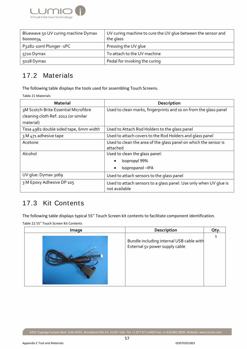
57
Appendix E Tool and Materials DO070201003
6355 Topanga Canyon Blvd. Suite #335, Woodland Hills CA, 91367 USA. Tel: +1 877 97 LUMIO Fax: +1 818 883 0858. Website: www.lumio.com
Bluewave 50 UV curing machine Dymax 60000034
UV curing machine to cure the UV glue between the sensor and the glass
P3282-10ml Plunger -1PC Pressing the UV glue
5720 Dymax To attach to the UV machine
5028 Dymax Pedal for invoking the curing
17.2 Materials
The following table displays the tools used for assembling Touch Screens.
Table 21 Materials
Material Description 3M Scotch-Brite Essential Microfibre cleaning cloth Ref: 2012 (or similar material)
Used to clean marks, fingerprints and so on from the glass panel
Tesa 4982 double sided tape, 6mm width Used to Attach Rod Holders to the glass panel 3 M 471 adhesive tape Used to attach covers to the Rod Holders and glass panel Acetone Used to clean the area of the glass panel on which the sensor is
attached Alcohol Used to clean the glass panel:
• Isopropyl 99% • Isopropanol –IPA
UV glue: Dymax 3069 Used to attach sensors to the glass panel 3 M Epoxy Adhesive DP 105 Used to attach sensors to a glass panel. Use only when UV glue is
not available
17.3 Kit Contents
The following table displays typical 55” Touch Screen kit contents to facilitate component identification.
Table 22 55” Touch Screen Kit Contents
Image Description Qty.
Bundle including internal USB cable with External 5v power supply cable
1

58
Appendix E Tool and Materials DO070201003
6355 Topanga Canyon Blvd. Suite #335, Woodland Hills CA, 91367 USA. Tel: +1 877 97 LUMIO Fax: +1 818 883 0858. Website: www.lumio.com
Image Description Qty.
PCB Controller 1
Extension PCB Controller
0/1
Jenoptic Sensor 2/4
2KC Sensor
2/4
Extension LED Wire cable
1

59
Appendix E Tool and Materials DO070201003
6355 Topanga Canyon Blvd. Suite #335, Woodland Hills CA, 91367 USA. Tel: +1 877 97 LUMIO Fax: +1 818 883 0858. Website: www.lumio.com
Image Description Qty.
FFC (flat) Cables 2/4
PCB LED wire 1/2
LED corner housing (Dual sensor systems only)
2
USB cable
1
Serial Cable
1

60
Table of Figures DO070201003
6355 Topanga Canyon Blvd. Suite #335, Woodland Hills CA, 91367 USA. Tel: +1 877 97 LUMIO Fax: +1 818 883 0858. Website: www.lumio.com
Chapter 18 Table of Figures Figure 1 Dual Sensor System .................................................................................................................3 Figure 2 Quad Sensor System ................................................................................................................3 Figure 3 Glass Flatness Test ................................................................................................................ 10 Figure 4 Rod Holder Cross Section ..................................................................................................... 13 Figure 5 Side Rod - Corner Housing Insertion .................................................................................... 13 Figure 6 Rod inserted into Corner Housing ........................................................................................ 14 Figure 7 Top End of Rod ..................................................................................................................... 14 Figure 8 Inserting the Side Rod into the Holder ................................................................................. 14 Figure 9 Inserting the Side Rod into the Holder ................................................................................. 14 Figure 10 Inserting a Reflector into a Rod Holder .............................................................................. 15 Figure 11 Dummy LED PCB ................................................................................................................. 15 Figure 12 Dummy LED PCB Cross Section ........................................................................................... 15 Figure 13 Rod Holder Cross Section ................................................................................................... 16 Figure 14 Assembled Rod Holder ....................................................................................................... 16 Figure 15 Attaching Double Sided Tape to Rod Holder and Corner ................................................... 16 Figure 16 Dual Sensor System Panel .................................................................................................. 16 Figure 17 LED Wiring for Dual Sensor Systems .................................................................................. 21 Figure 18 LED Wiring .......................................................................................................................... 21 Figure 19 Led Wiring – Corner Housing .............................................................................................. 22 Figure 20 LED Wiring .......................................................................................................................... 22 Figure 21 LED Corner Wiring .............................................................................................................. 23 Figure 22 LED Wire Insertion into Rod Holder ................................................................................... 23 Figure 23 Rear Cover Assembly .......................................................................................................... 23 Figure 24 LED Wire - PCB Controller Connection ............................................................................... 23 Figure 25 LED Wiring for Dual Sensor Systems .................................................................................. 24 Figure 26 LED Wiring for a Quad Sensor System including an Extension PCB Controller .................. 25 Figure 27 Sensor Corner Holder ......................................................................................................... 26 Figure 28 Inserting a Screw into the Sensor Holder ........................................................................... 27 Figure 29 Sensor placed on Sensor Holder ......................................................................................... 27 Figure 30 Sensor on Glass Panel ......................................................................................................... 28 Figure 31 Clean Glass with Acetone ................................................................................................... 28 Figure 32 Cleaning the Sensor ............................................................................................................ 29 Figure 33 Dymax 3069 Dispenser ....................................................................................................... 29 Figure 34 Dispense: 450 gauge – Purple Tip....................................................................................... 29 Figure 35 Dispense tip: TE 21 Gauge - Purple..................................................................................... 29 Figure 36 Dispense: 450 gauge – Yellow Tip ...................................................................................... 29 Figure 37 Needle attached to Dymax Dispenser ................................................................................ 29 Figure 38 Attaching Dymax Adhesive to Glass ................................................................................... 30 Figure 39 Attaching Sensor to Glass Panel ......................................................................................... 30 Figure 40 Curing Adhesive with an UV Machine ................................................................................ 31

61
Table of Figures DO070201003
6355 Topanga Canyon Blvd. Suite #335, Woodland Hills CA, 91367 USA. Tel: +1 877 97 LUMIO Fax: +1 818 883 0858. Website: www.lumio.com
Figure 41 3M EPX Plus II Applicator.................................................................................................... 32 Figure 42 Sealing glue: 3M Epoxy glue DP105.................................................................................... 32 Figure 43 Removing lumps of glue ..................................................................................................... 32 Figure 44 Mixing the epoxy ................................................................................................................ 32 Figure 45 Spreading the Epoxy on the Sensor .................................................................................... 33 Figure 46 Connecting a Sensor to a Flat Cable ................................................................................... 34 Figure 47 PCB Controller Connections ............................................................................................... 35 Figure 48 Connecting a Sensor to the PCB Controller ........................................................................ 35 Figure 49 Inserting Flat Cables into Connectors ................................................................................. 36 Figure 50 Direct 2 KC sensor - PCB Controller Connectivity ............................................................... 37 Figure 51 Flat (FFC) Cable - Sensor Connection .................................................................................. 37 Figure 52 PCB Controller - Flat Cable Connection .............................................................................. 38 Figure 53 PCB Controller Connectivity with a Flat Cable Adaptor ..................................................... 38 Figure 54 : Cable Adaptor - 0.5 mm Flat Cable Connection ............................................................... 39 Figure 55 Cable Adaptor - 1 mm Flat Cable Connection .................................................................... 39 Figure 56 : PCB Controller - 1 mm Flat Cable Connection .................................................................. 39 Figure 57 Extension PCB Controller Front View .......................... Figure 58 Extension PCB Rear View 40 Figure 59 LED Power Control Wire Bundle ......................................................................................... 40 Figure 60 PCB Controller connected to an Extension PCB Controller ................................................ 41 Figure 61 OQC Touch Screen Dimension Verification ........................................................................ 45 Figure 62 Tools ................................................................................................................................... 51 Figure 63 Removing the Cover from the Rod Holder ......................................................................... 52 Figure 64 Removing the Reflector from the Rod Holder .................................................................... 52 Figure 65 Removing the IR Rod from the Rod Holder ........................................................................ 53 Figure 66 Loosening the Active Barrier .............................................................................................. 53 Figure 67 Cutting the Rod Holder ....................................................................................................... 53 Figure 68 Filing the IR Rod .................................................................................................................. 54 Figure 69 Painting the IR Rod ............................................................................................................. 54 Figure 70 Painting the IR Rod ............................................................................................................. 54

62
Table of Tables DO070201003
6355 Topanga Canyon Blvd. Suite #335, Woodland Hills CA, 91367 USA. Tel: +1 877 97 LUMIO Fax: +1 818 883 0858. Website: www.lumio.com
Chapter 19 Table of Tables Table 1: System Components ................................................................................................................4 Table 2: Lumio Packing List ....................................................................................................................6 Table 3: Touch Panel Inspection Conditions .........................................................................................7 Table 4 Types of Glass ...........................................................................................................................8 Table 5 Touch Screen Glass Panel Circular and Linear Defect Limitations ............................................8 Table 6 Touch Screen Glass Panel Mechanical Acceptance / Rejection Criteria ...................................9 Table 7 Touch Screen Glass Crack Criteria ............................................................................................9 Table 8 Glass Flatness for Panels ........................................................................................................ 10 Table 9 Glass Flatness Test Components ........................................................................................... 11 Table 10 Manual Assembly Kit ........................................................................................................... 18 Table 11 Tools and Materials ............................................................................................................. 29 Table 12 Adhedsive Tools and Materials ............................................................................................ 32 Table 13 Preparing the DP 105 Adhesive ........................................................................................... 32 Table 14 2 KC sensor -flat cable Connectivity Components in a Quad Sensor System2 KC sensor -flat cable Connectivity Components in a Quad Sensor System ......................................................................... 36 Table 15 Touch Screen Glass Panel Mechanical Criteria .................................................................... 43 Table 16 Touch Screen Glass Crack Criteria ....................................................................................... 44 Table 17 Components Inspection ....................................................................................................... 44 Table 18 Sensor Adhesion Requirements ........................................................................................... 46 Table 19 Adhesive Types in Different Environments ......................................................................... 47 Table 20 Tools ..................................................................................................................................... 56 Table 21 Materials .............................................................................................................................. 57 Table 22 55” Touch Screen Kit Contents ............................................................................................ 57

63
Table of Tables DO070201003
6355 Topanga Canyon Blvd. Suite #335, Woodland Hills CA, 91367 USA. Tel: +1 877 97 LUMIO Fax: +1 818 883 0858. Website: www.lumio.com
Acceptance / Rejection Criteria for Glass Defects, 9 Active Barrier Assembly for Dual Sensor Systems,
12 Active Barrier Assembly for Quad Sensor Systems,
17 Adhesive Curing Requirements, 48 Adhesives, 47 Assembling the Active Barrier, 12 Attaching Sensors to the Glass Panel with DP 105
Epoxy, 31 Attaching Sensors to the Glass Panel with Dymax
3069 Epoxy, 27 Attaching Sensors to the Touch Screen Glass Panel,
26 Attaching the Active Barrier to the Touch Screen
Glass Panel, 18 Circular and Linear Defect Criteria, 8 Cleaning, 7 Cleaning Materials, 56 Connecting 2 KC Sensors, 36 Connecting a 2 KC Sensor to a PCB Controller with
a Flat Cable Adaptor, 38 Connecting a PCB Controller to an Extension PCB
Controller, 40 Connecting Jenoptic Sensors, 34 Connecting the Sensors to the PCB Controller, 34 Creating a 1 mm gap between the Sensor and the
Active Barrier, 51
Direct 2 KC Sensor - PCB Controller Connection, 37 Distribution Ready Procedure, 42 Glass Crack Criteria, 9 Glass Flatness Test, 10 Glass Surface Flatness, 10 Glue Curing Time, 48 Glue Curing Tool Power Density, 48 Incoming Components Inspection, 6 Incoming Glass Panel Inspection, 7 Incoming Quality Control, 6 Installing Crystal Touch Manager, 28, 49 Kit Contents, 57 LED PCB Wiring, 21 LED PCB wiring for Dual Sensor Systems, 21 LED Wiring for Quad Sensor systems, 24 LED Wiring for Quad Sensor Systems with an
Extension PCB Controller, 25 LED Wiring for Quad Sensor Systems without an
Extension PCB Controller, 24 Lumio UV Glue Curing Tool, 48 OQC Outgoing Quality Control, 42 Placing Components on Glass, 11 Primers, 46 Sensor Adhesion Requirements, 46 Tool and Materials, 56 Types of Glass, 8 Work Flow, 5