
"Lucky" Final Report
45
Final Project Report “Lucky” Prof: Robert Shaefer TA: James Simonelli Team 13 Jonathan Chang Eujin Chung Brandon Judoprasetijo MAE-94: Computer Aided Design and Drafting Fall 2014 Mechanical & Aerospace Engineering Department University of California, Los Angeles 12/16/2014
-
Upload
brandonjudoprasetijo -
Category
Documents
-
view
26 -
download
0
description
Team 13.
Transcript of "Lucky" Final Report
Final Project Report
“Lucky”
Prof: Robert Shaefer TA: James Simonelli
Team 13 Jonathan Chang
Eujin Chung Brandon Judoprasetijo
MAE-94: Computer Aided Design and Drafting Fall 2014
Mechanical & Aerospace Engineering Department University of California, Los Angeles
12/16/2014
ii
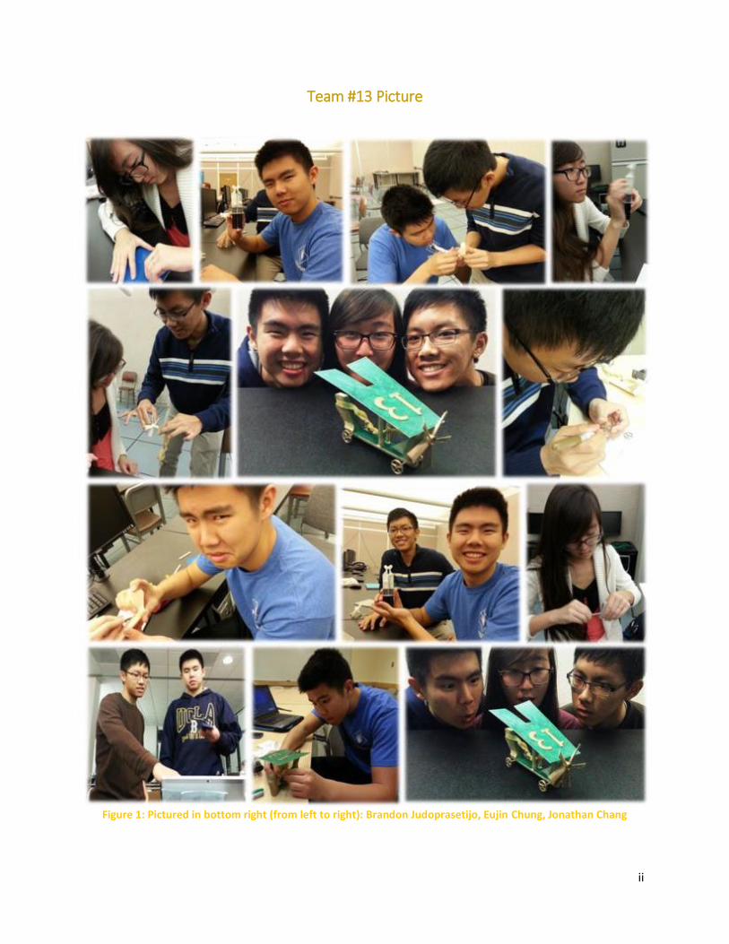
Team #13 Picture
Figure 1: Pictured in bottom right (from left to right): Brandon Judoprasetijo, Eujin Chung, Jonathan Chang
iii
Abstract
For years, the task of transporting objects through the use of a rubber band has led to redundant
designs focused on travel by land. This report documents our innovative design that utilizes energy from
a rubber band to generate airflow and lift. First, we will cover the design challenges followed by a review
of other “state-of-the-art” designs available online. Next, we will provide the progression of our design
concepts and the specifications of our final design. Lastly, we will discuss the analysis performed, the
product fabrication process, and our results.
iv
Table of Contents
Team #13 Picture .......................................................................................................................................... ii
Abstract ........................................................................................................................................................ iii
Table of Contents ..................................................................................................................................... iv
Table of Figures ............................................................................................................................................. v
List of Tables ............................................................................................................................................... vii
List of Symbols ........................................................................................................................................... viii
1. Introduction .............................................................................................................................................. 1
2. Design Requirements ................................................................................................................................ 1
3. Prior Work (“state-of-the-art”) ................................................................................................................. 1
4. Concept Development .............................................................................................................................. 3
4.1 Design Concept 1 ................................................................................................................................ 3
4.2 Design Concept 2 ................................................................................................................................ 3
4.3 Design Concept 3 ................................................................................................................................ 4
4.4 Selected Design Concept ..................................................................................................................... 5
5. Design Specifications ................................................................................................................................ 5
5.1 Final Design Description ...................................................................................................................... 6
5.2 Device Parts Design ............................................................................................................................. 8
5.3 Powering the Device ............................................................................................................................. 16
6. Calculations and Analysis ........................................................................................................................ 18
7. Product Fabrication ................................................................................................................................. 20
8. Product Testing and Evaluation .............................................................................................................. 22
9. Design Requirement Satisfaction ............................................................................................................ 22
.................................................................................................................................................................... 24
10. Conclusion ....................................................................................................................................... 25
11. References ............................................................................................................................................ 26
12. Appendix ............................................................................................................................................... 27
12.1 Part Drawings .................................................................................................................................. 27
.................................................................................................................................................................... 36
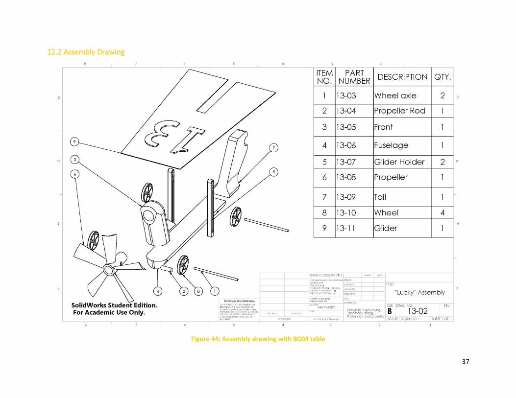
12.2 Assembly Drawing ........................................................................................................................... 36
................................................................................................................................................................ 37
v
Table of Figures Figure 1: Pictured in bottom right (from left to right): Brandon Judoprasetijo, Eujin Chung, Jonathan
Chang ............................................................................................................................................................ ii
Figure 2: Example of two car designs where the rubber band gives power to the axle. Left: [1] Right: [2] 2
Figure 3: Airplane design where rubber band powers propeller [3] ............................................................ 2
Figure 4: Chang's first design concept. ......................................................................................................... 3
Figure 5: Judoprasetijo's first design concept. .............................................................................................. 4
Figure 6: Chung's first design concept. ......................................................................................................... 5
Figure 7: Exploded view of all the final parts. ............................................................................................... 6
Figure 8: Pictorial of final product from different views. ............................................................................. 7
Figure 9: Isometric views of the fuselage on SolidWorks (left) and the actual product (right) .................... 8
Figure 10: From left to right: actual 3D printed wheel axles and isometric view of the SolidWorks model 8
Figure 11: From left to right: front and side views of the SolidWorks model of the wheel axle .................. 9
Figure 12: From left to right: final 3D printed wheel product and isometric view of SolidWorks model. ... 9
Figure 13: Isometric views of the actual front (left) and the SolidWorks model (right) ............................. 10
Figure 14: Bottom views of the actual front (left) and SolidWorks model (right) ...................................... 10
Figure 15: Front views of the actual front part (left) and the SolidWorks model (right) ........................... 11
Figure 16: Front views of the actual propeller (left) and the SolidWorks model (right) ............................ 11
Figure 17: Side views of the actual propeller (left) and the SolidWorks model (right) .............................. 12
Figure 18: From left to right: front and top views of the propeller rod on SolidWorks ............................. 12
Figure 19: Side views of the actual 3D printed tail (left) and the Solidworks model (right)....................... 13
Figure 20: From left to right: top and isometric views of the tail part on the SolidWorks model ............. 13
Figure 21: From left to right: an isometric view of the final glider holder and the side view of the
SolidWorks model ....................................................................................................................................... 14
Figure 22: Front view of the glider holder on SolidWorks model ............................................................... 14
Figure 23: Bottom views of the actual glider (left) and the SolidWorks model (right)............................... 15
Figure 24: Top views of the actual glider (left) and the SolidWorks model (right) ..................................... 15
Figure 25: Assembling the rubber band and propeller ............................................................................... 16
Figure 26: The blue arrow indicates how the air will be scooped by the propeller ................................... 17
Figure 27: The red arrow indicates the direction the propeller rotates ..................................................... 17
Figure 28: The blue arrow indicates the flow of air along the entire device; the white arrow shows the
direction of travel ....................................................................................................................................... 17
Figure 29: Displays the total mass and center of gravity of our final device .............................................. 18
Figure 30: Graph of force versus displacement in order to find the spring constant ................................ 19
Figure 31: STL models of various parts ready to add to the pack file ......................................................... 21
Figure 32: Screenshot of the Pack file ready for printing ........................................................................... 21
Figure 33: From left to right: the top, side, and front view of the final product ........................................ 24
Figure 34: From left to right: the top, side, and front view of the final SolidWorks model ....................... 24
Figure 35: Engineering drawing of the front part ....................................................................................... 28
Figure 36: Engineering drawing of the back part ........................................................................................ 29
Figure 37: Engineering drawing of the fuselage ......................................................................................... 30
vi
Figure 38: Engineering drawing of the propeller ........................................................................................ 31
Figure 39: Engineering drawing of the propeller rod ................................................................................. 32
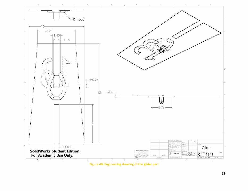
Figure 40: Engineering drawing of the glider part ...................................................................................... 33
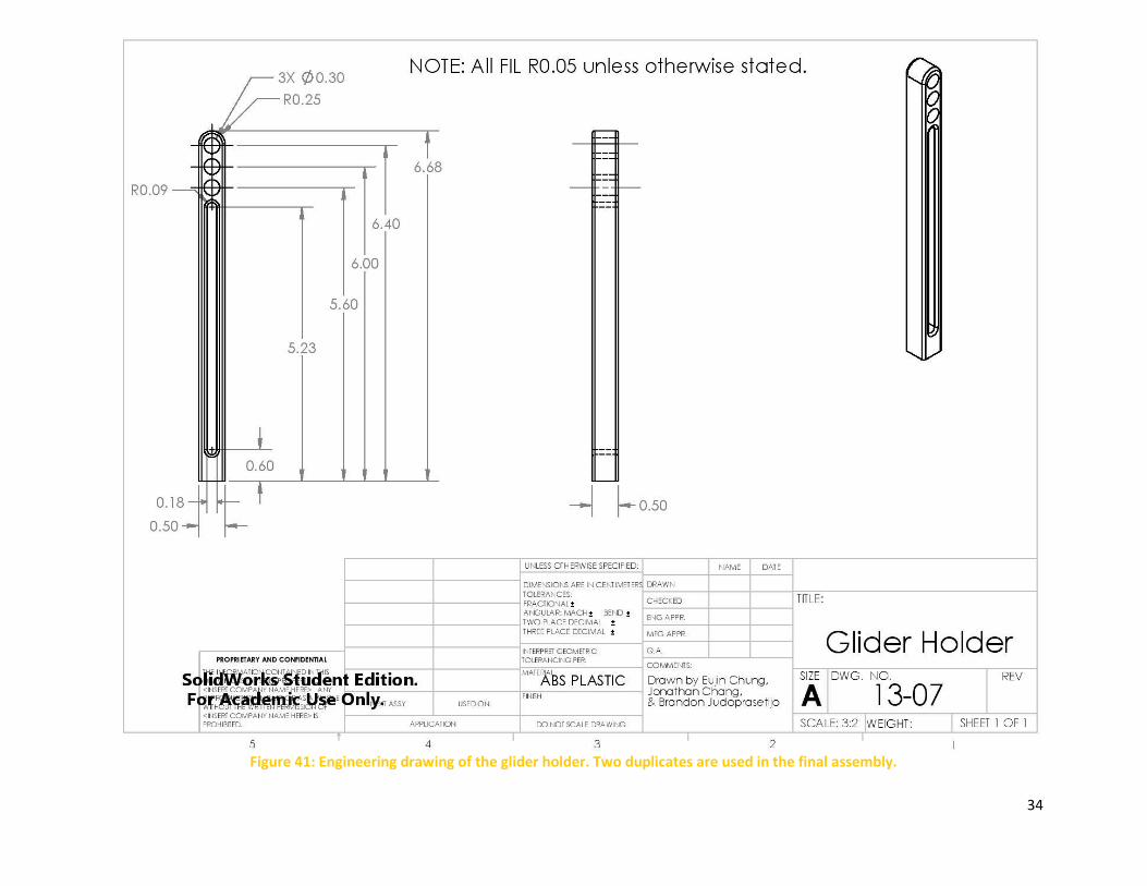
Figure 41: Engineering drawing of the glider holder. Two duplicates are used in the final assembly. ...... 34
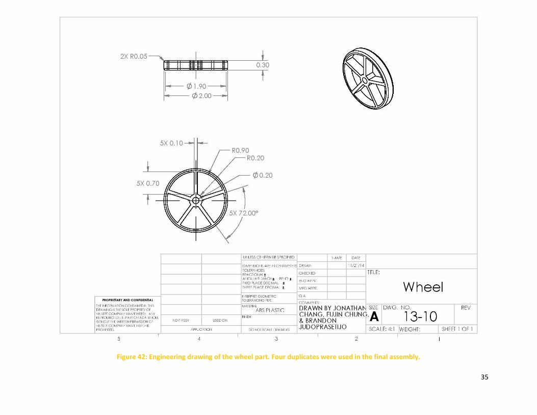
Figure 42: Engineering drawing of the wheel part. Four duplicates were used in the final assembly. ...... 35
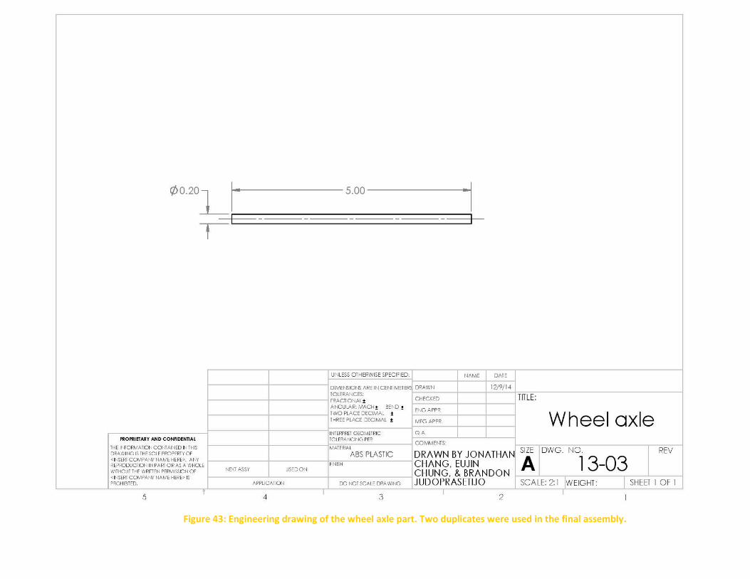
Figure 43: Engineering drawing of the wheel axle part. Two duplicates were used in the final assembly.
.................................................................................................................................................................... 36
Figure 44: Assembly drawing with BOM table ............................................................................................ 37
vii
List of Tables Table 1: Device Dimensions .......................................................................................................................... 6
Table 2: Mass, Force, and Displacement Data for estimating the elastic constant (k) of the rubber band19
Table 3: Data and measurements used to calculate the total potential energy ........................................ 20
Table 4: Data from testing our device ........................................................................................................ 22
Table 5: Design requirement satisfaction ................................................................................................... 23
viii
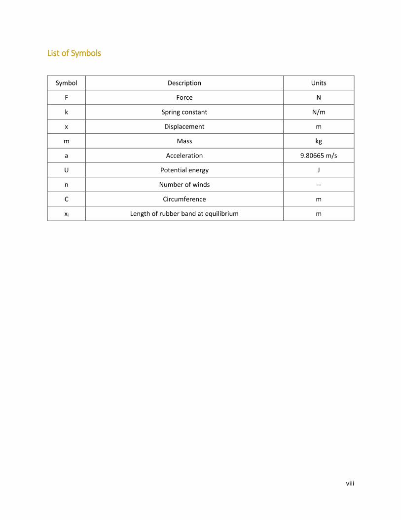
List of Symbols
Symbol Description Units
F Force N
k Spring constant N/m
x Displacement m
m Mass kg
a Acceleration 9.80665 m/s
U Potential energy J
n Number of winds --
C Circumference m
xi Length of rubber band at equilibrium m
1
1. Introduction
We were challenged to design and build a small rubber band powered device capable of traveling
a horizontal distance. Past engineers thoroughly explored the concept of car-inspired vehicles powered
by winding up rubber bands around wheel axles. Our team has successfully created a stylish, light weight
vehicle that, unlike most other designs, is powered using a propeller. The bulk of the device is made of
acrylonitrile butadiene styrene (ABS) plastic and the parts are 3D printed. Upon completion, our team’s
design will compete against other classmates’ designs. Our team’s goal is to create a vehicle that not only
operates efficiently, but also stands out creatively and aesthetically amongst the competition. Our design
is sure to do both.
2. Design Requirements The requirements and parameters for this project are outlined below:
1. The device must be powered by rubber bands
2. The device must be able to transport itself across a horizontal surface
3. Up to three rubber bands may be used
4. The rubber bands may be manipulated into any shape
5. The device must be self-contained
6. The entire device, including rubber bands, must be transported
7. The device must be made of ABS plastic, except for auxiliary parts
8. Adhesives may be used, but adhesive tapes are restricted
9. The maximum dimensions are 10 by 10 by 20 centimeters
10. All primary parts of the device must be fabricated using the Dimension Elite 1200 printer
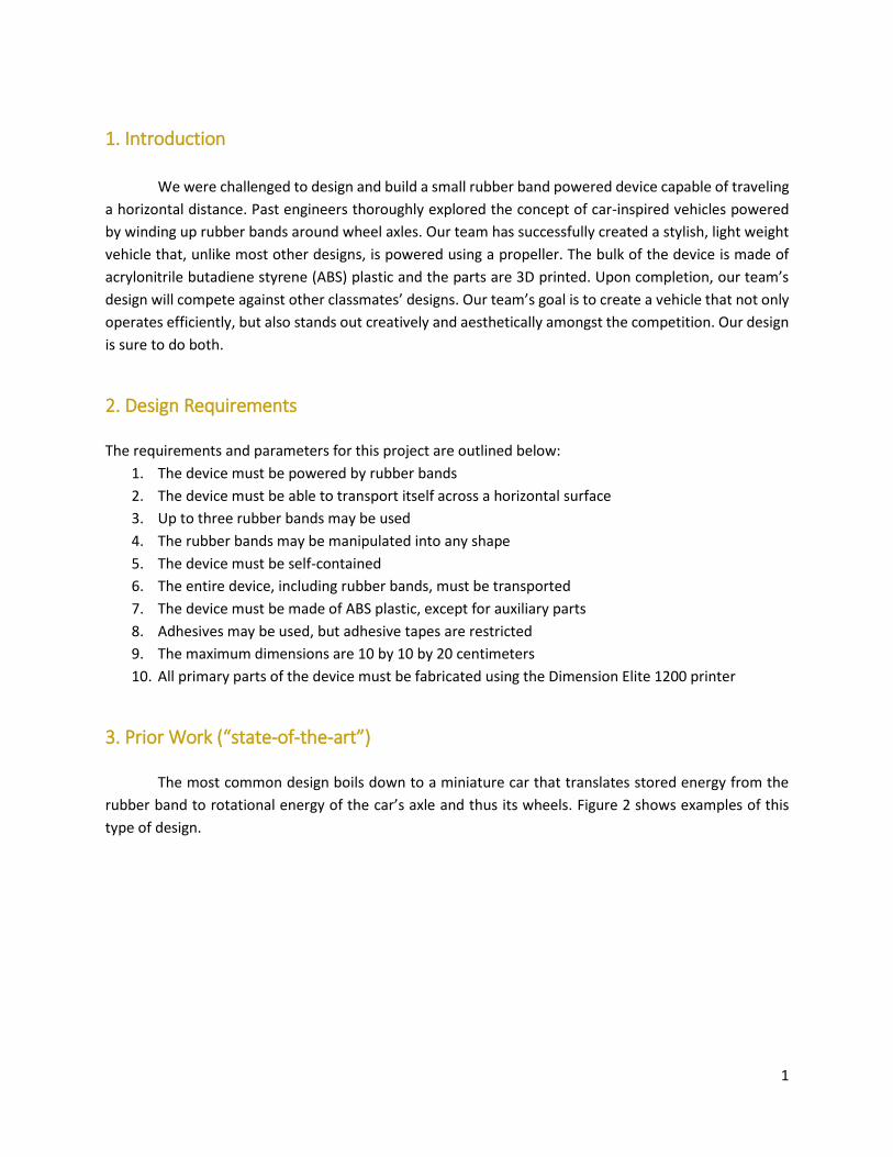
3. Prior Work (“state-of-the-art”)
The most common design boils down to a miniature car that translates stored energy from the
rubber band to rotational energy of the car’s axle and thus its wheels. Figure 2 shows examples of this
type of design.
2
Figure 2: Example of two car designs where the rubber band gives power to the axle. Left: [1] Right: [2]
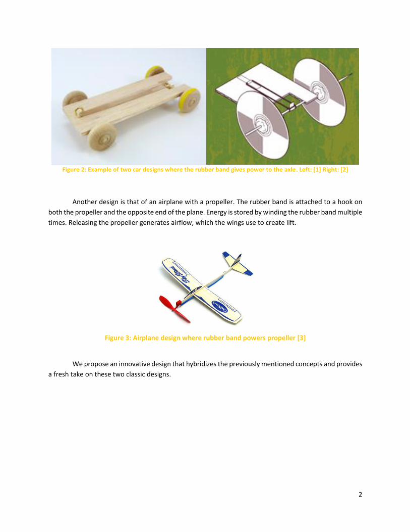
Another design is that of an airplane with a propeller. The rubber band is attached to a hook on
both the propeller and the opposite end of the plane. Energy is stored by winding the rubber band multiple
times. Releasing the propeller generates airflow, which the wings use to create lift.
Figure 3: Airplane design where rubber band powers propeller [3]
We propose an innovative design that hybridizes the previously mentioned concepts and provides
a fresh take on these two classic designs.
3
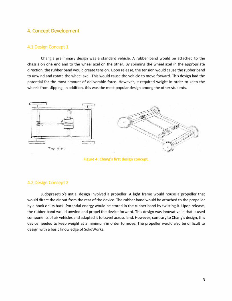
4. Concept Development
4.1 Design Concept 1
Chang’s preliminary design was a standard vehicle. A rubber band would be attached to the
chassis on one end and to the wheel axel on the other. By spinning the wheel axel in the appropriate
direction, the rubber band would create tension. Upon release, the tension would cause the rubber band
to unwind and rotate the wheel axel. This would cause the vehicle to move forward. This design had the
potential for the most amount of deliverable force. However, it required weight in order to keep the
wheels from slipping. In addition, this was the most popular design among the other students.
Figure 4: Chang's first design concept.
4.2 Design Concept 2
Judoprasetijo’s initial design involved a propeller. A light frame would house a propeller that
would direct the air out from the rear of the device. The rubber band would be attached to the propeller
by a hook on its back. Potential energy would be stored in the rubber band by twisting it. Upon release,
the rubber band would unwind and propel the device forward. This design was innovative in that it used
components of air vehicles and adapted it to travel across land. However, contrary to Chang’s design, this
device needed to keep weight at a minimum in order to move. The propeller would also be difficult to
design with a basic knowledge of SolidWorks.
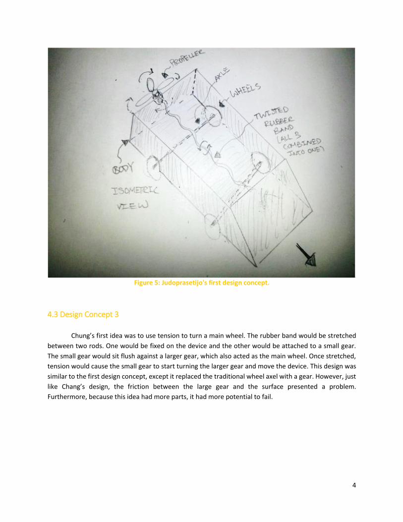
4
Figure 5: Judoprasetijo's first design concept.
4.3 Design Concept 3
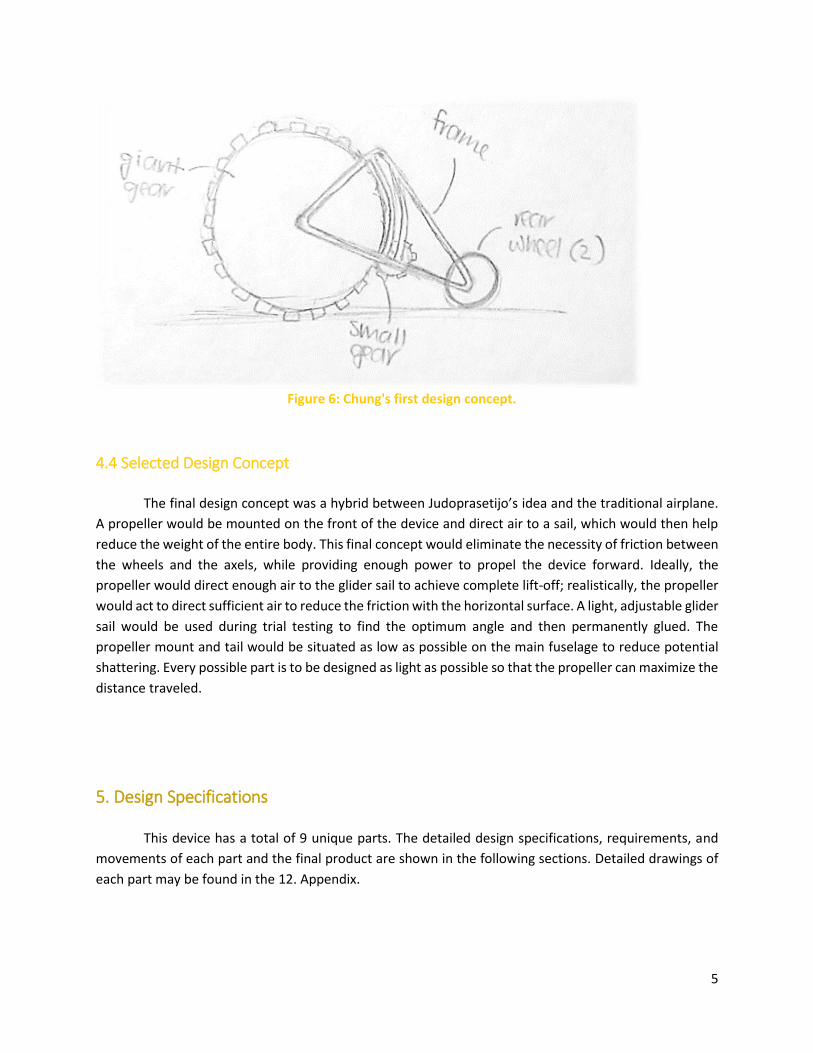
Chung’s first idea was to use tension to turn a main wheel. The rubber band would be stretched
between two rods. One would be fixed on the device and the other would be attached to a small gear.
The small gear would sit flush against a larger gear, which also acted as the main wheel. Once stretched,
tension would cause the small gear to start turning the larger gear and move the device. This design was
similar to the first design concept, except it replaced the traditional wheel axel with a gear. However, just
like Chang’s design, the friction between the large gear and the surface presented a problem.
Furthermore, because this idea had more parts, it had more potential to fail.
5
Figure 6: Chung's first design concept.
4.4 Selected Design Concept
The final design concept was a hybrid between Judoprasetijo’s idea and the traditional airplane.
A propeller would be mounted on the front of the device and direct air to a sail, which would then help
reduce the weight of the entire body. This final concept would eliminate the necessity of friction between
the wheels and the axels, while providing enough power to propel the device forward. Ideally, the
propeller would direct enough air to the glider sail to achieve complete lift-off; realistically, the propeller
would act to direct sufficient air to reduce the friction with the horizontal surface. A light, adjustable glider
sail would be used during trial testing to find the optimum angle and then permanently glued. The
propeller mount and tail would be situated as low as possible on the main fuselage to reduce potential
shattering. Every possible part is to be designed as light as possible so that the propeller can maximize the
distance traveled.
5. Design Specifications
This device has a total of 9 unique parts. The detailed design specifications, requirements, and
movements of each part and the final product are shown in the following sections. Detailed drawings of
each part may be found in the 12. Appendix.
6
5.1 Final Design Description
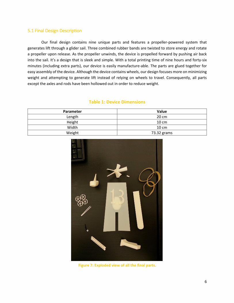
Our final design contains nine unique parts and features a propeller-powered system that
generates lift through a glider sail. Three combined rubber bands are twisted to store energy and rotate
a propeller upon release. As the propeller unwinds, the device is propelled forward by pushing air back
into the sail. It’s a design that is sleek and simple. With a total printing time of nine hours and forty-six
minutes (including extra parts), our device is easily manufacture-able. The parts are glued together for
easy assembly of the device. Although the device contains wheels, our design focuses more on minimizing
weight and attempting to generate lift instead of relying on wheels to travel. Consequently, all parts
except the axles and rods have been hollowed out in order to reduce weight.
Table 1: Device Dimensions
Parameter Value
Length 20 cm
Height 10 cm
Width 10 cm
Weight 73.32 grams
Figure 7: Exploded view of all the final parts.
7
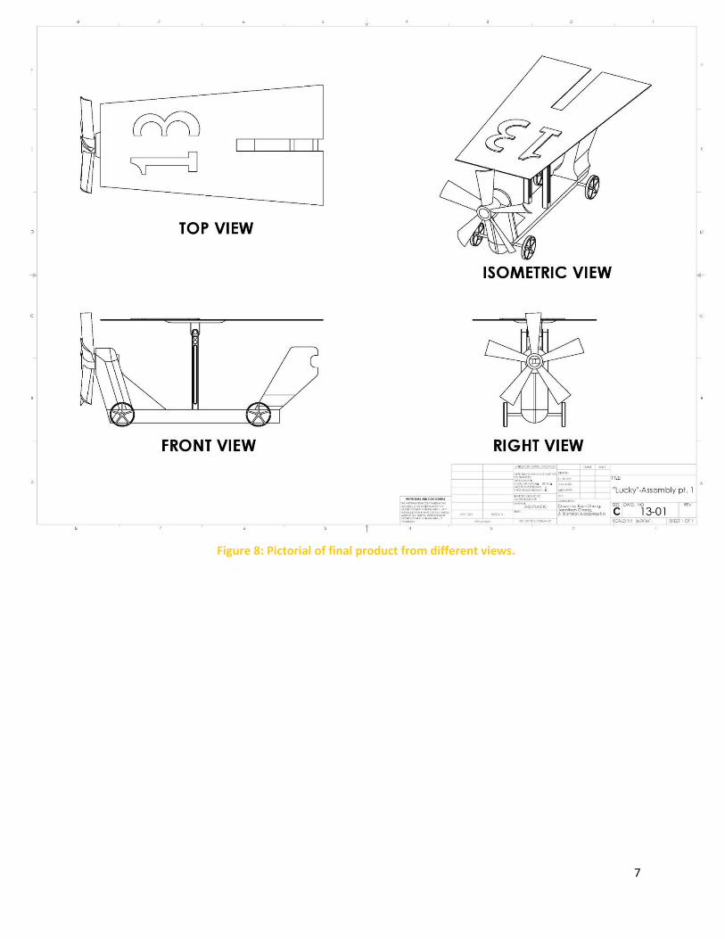
Figure 8: Pictorial of final product from different views.
8
5.2 Device Parts Design
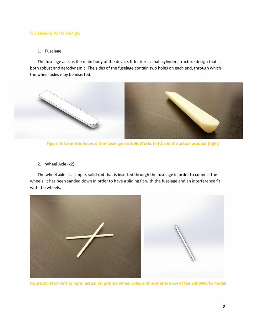
1. Fuselage
The fuselage acts as the main body of the device. It features a half cylinder structure design that is
both robust and aerodynamic. The sides of the fuselage contain two holes on each end, through which
the wheel axles may be inserted.
2. Wheel Axle (x2)
The wheel axle is a simple, solid rod that is inserted through the fuselage in order to connect the
wheels. It has been sanded down in order to have a sliding fit with the fuselage and an interference fit
with the wheels.
Figure 9: Isometric views of the fuselage on SolidWorks (left) and the actual product (right)
Figure 10: From left to right: actual 3D printed wheel axles and isometric view of the SolidWorks model
9
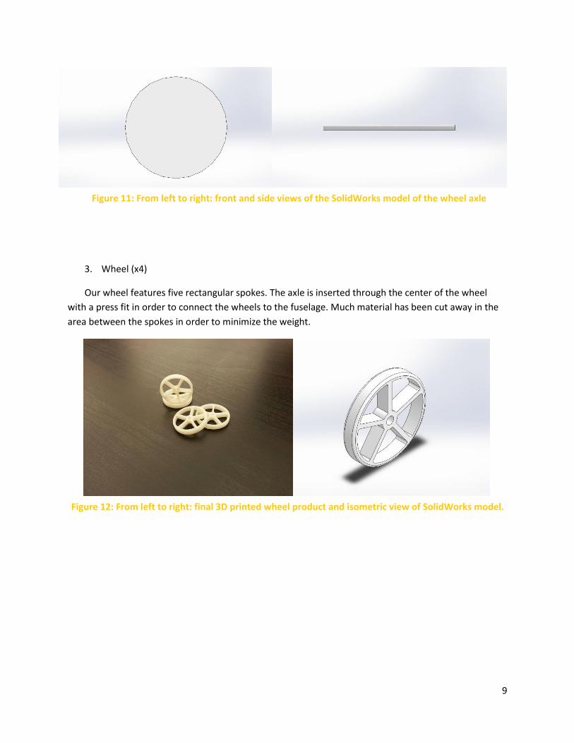
3. Wheel (x4)
Our wheel features five rectangular spokes. The axle is inserted through the center of the wheel
with a press fit in order to connect the wheels to the fuselage. Much material has been cut away in the
area between the spokes in order to minimize the weight.
Figure 11: From left to right: front and side views of the SolidWorks model of the wheel axle
Figure 12: From left to right: final 3D printed wheel product and isometric view of SolidWorks model.
10
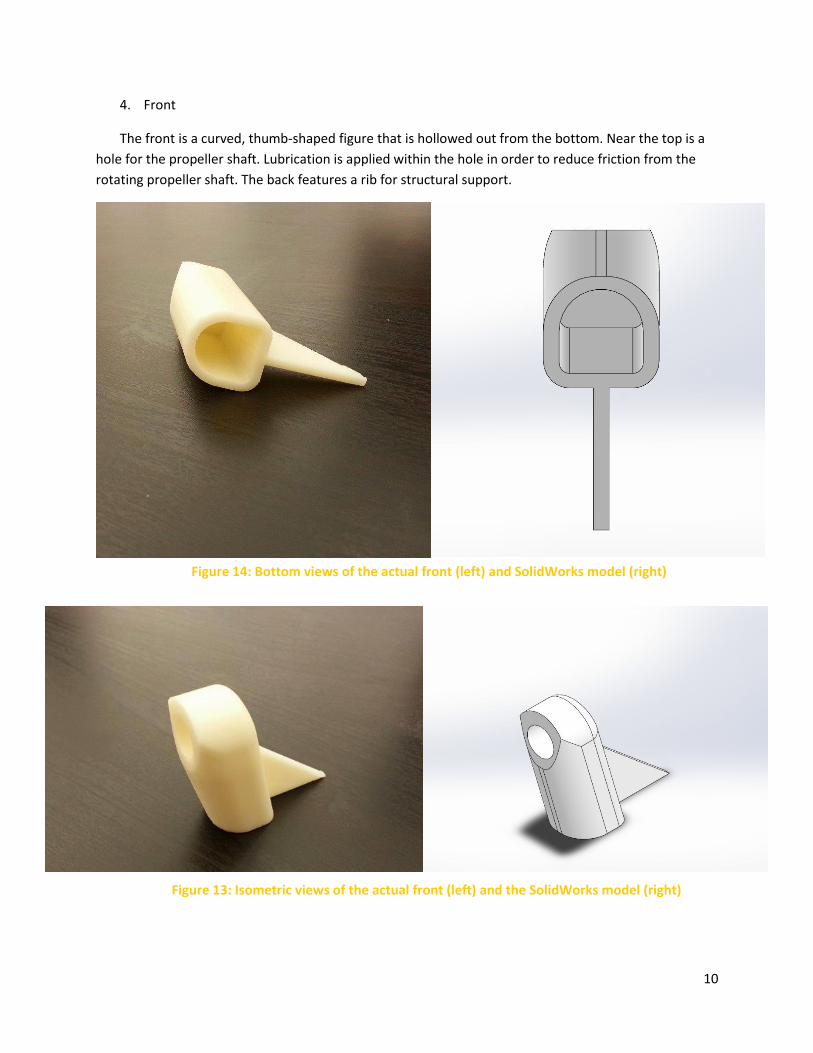
4. Front
The front is a curved, thumb-shaped figure that is hollowed out from the bottom. Near the top is a
hole for the propeller shaft. Lubrication is applied within the hole in order to reduce friction from the
rotating propeller shaft. The back features a rib for structural support.
Figure 13: Isometric views of the actual front (left) and the SolidWorks model (right)
Figure 14: Bottom views of the actual front (left) and SolidWorks model (right)
11
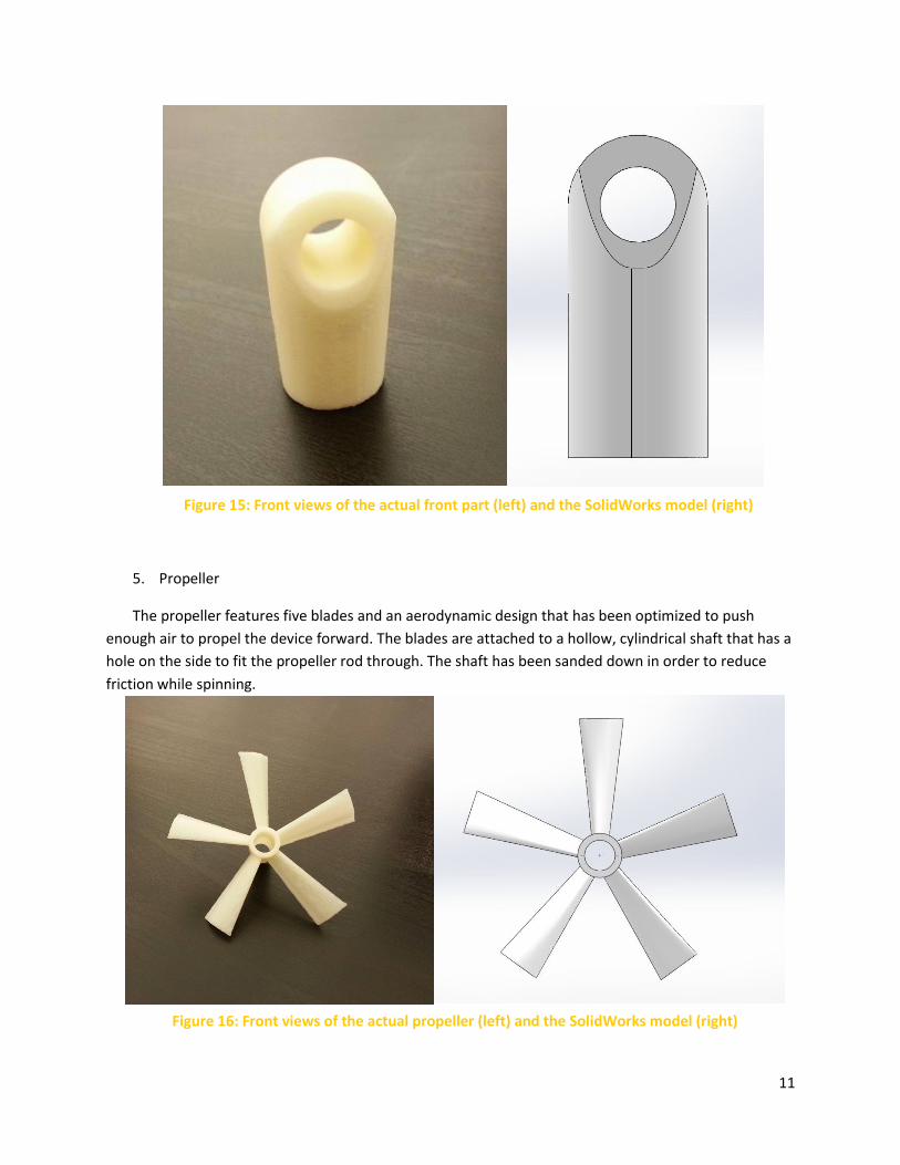
5. Propeller
The propeller features five blades and an aerodynamic design that has been optimized to push
enough air to propel the device forward. The blades are attached to a hollow, cylindrical shaft that has a
hole on the side to fit the propeller rod through. The shaft has been sanded down in order to reduce
friction while spinning.
Figure 15: Front views of the actual front part (left) and the SolidWorks model (right)
Figure 16: Front views of the actual propeller (left) and the SolidWorks model (right)
12
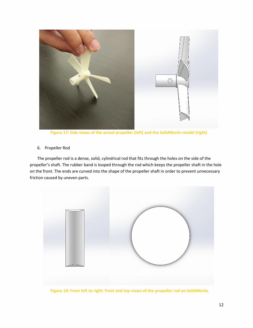
6. Propeller Rod
The propeller rod is a dense, solid, cylindrical rod that fits through the holes on the side of the
propeller’s shaft. The rubber band is looped through the rod which keeps the propeller shaft in the hole
on the front. The ends are curved into the shape of the propeller shaft in order to prevent unnecessary
friction caused by uneven parts.
Figure 17: Side views of the actual propeller (left) and the SolidWorks model (right)
Figure 18: From left to right: front and top views of the propeller rod on SolidWorks
13
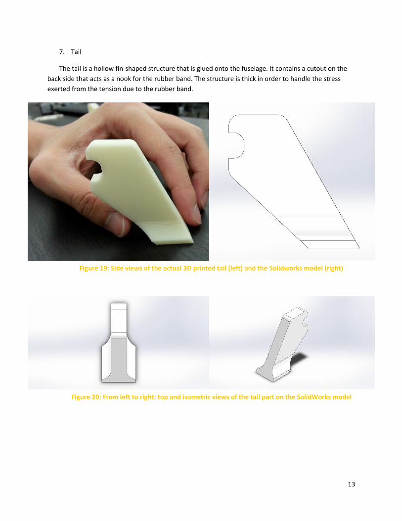
7. Tail
The tail is a hollow fin-shaped structure that is glued onto the fuselage. It contains a cutout on the
back side that acts as a nook for the rubber band. The structure is thick in order to handle the stress
exerted from the tension due to the rubber band.
Figure 19: Side views of the actual 3D printed tail (left) and the Solidworks model (right)
Figure 20: From left to right: top and isometric views of the tail part on the SolidWorks model
14
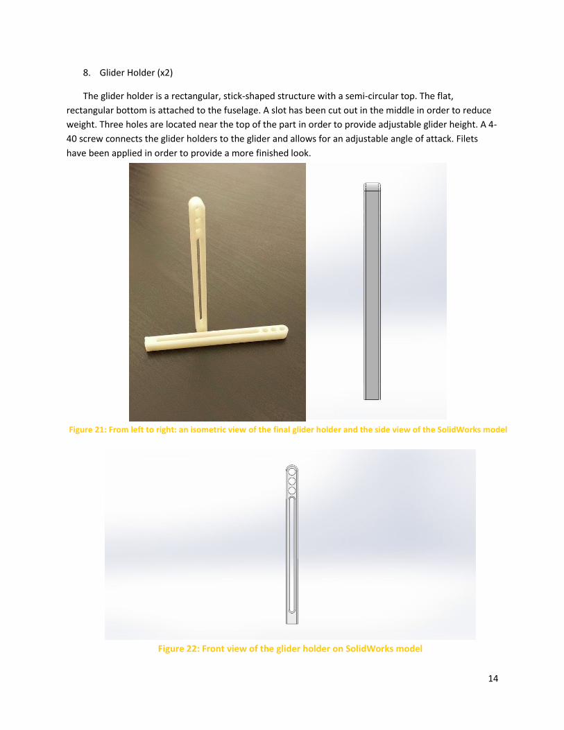
8. Glider Holder (x2)
The glider holder is a rectangular, stick-shaped structure with a semi-circular top. The flat,
rectangular bottom is attached to the fuselage. A slot has been cut out in the middle in order to reduce
weight. Three holes are located near the top of the part in order to provide adjustable glider height. A 4-
40 screw connects the glider holders to the glider and allows for an adjustable angle of attack. Filets
have been applied in order to provide a more finished look.
Figure 21: From left to right: an isometric view of the final glider holder and the side view of the SolidWorks model
Figure 22: Front view of the glider holder on SolidWorks model
15
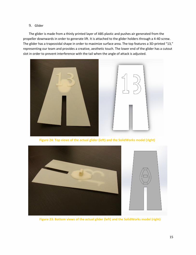
9. Glider
The glider is made from a thinly printed layer of ABS plastic and pushes air generated from the
propeller downwards in order to generate lift. It is attached to the glider holders through a 4-40 screw.
The glider has a trapezoidal shape in order to maximize surface area. The top features a 3D-printed “13,”
representing our team and provides a creative, aesthetic touch. The lower end of the glider has a cutout
slot in order to prevent interference with the tail when the angle of attack is adjusted.
Figure 24: Top views of the actual glider (left) and the SolidWorks model (right)
Figure 23: Bottom views of the actual glider (left) and the SolidWorks model (right)
16
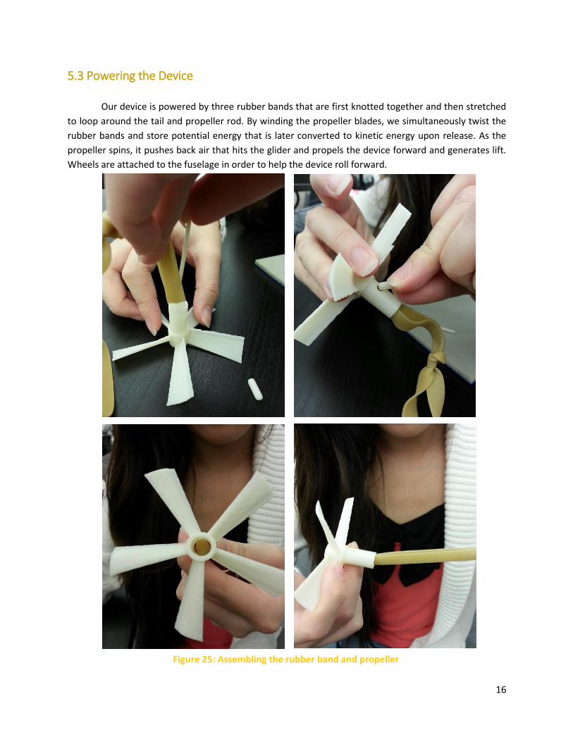
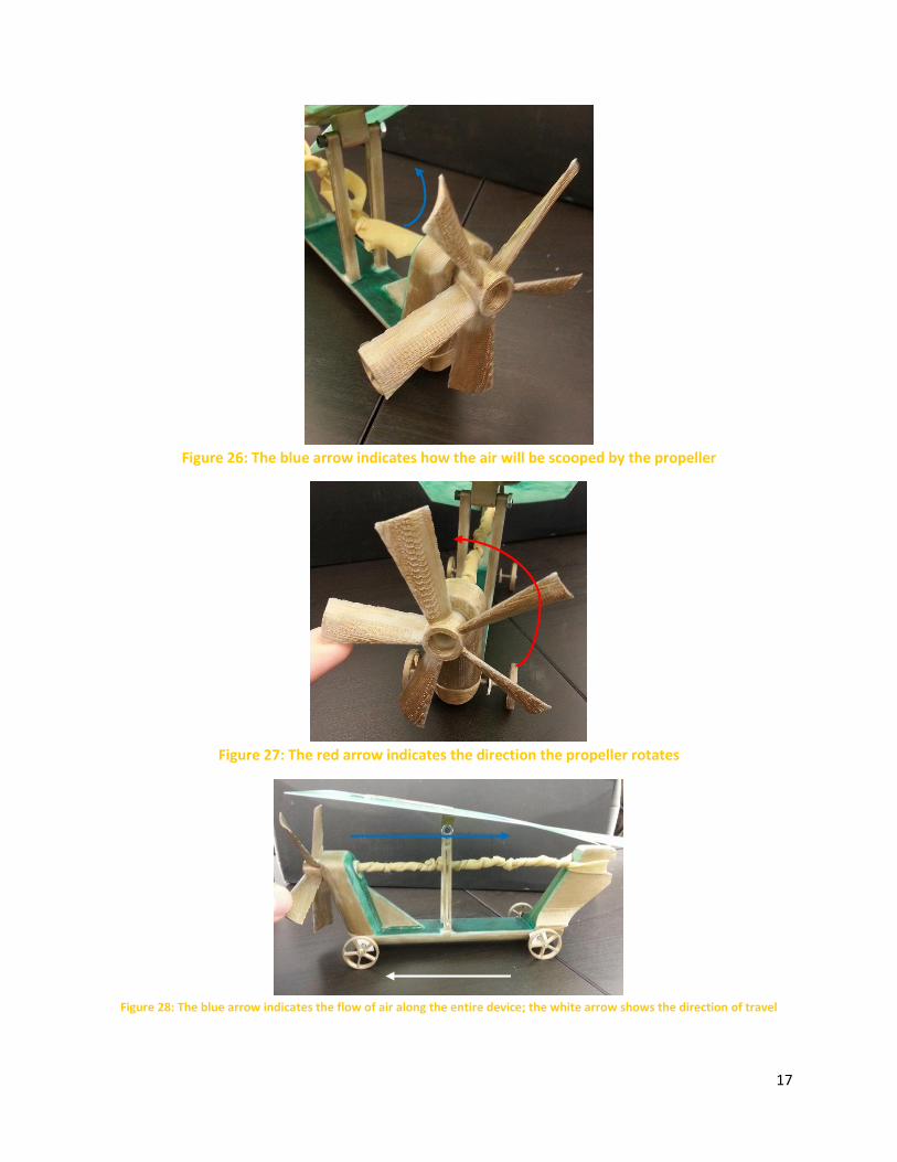
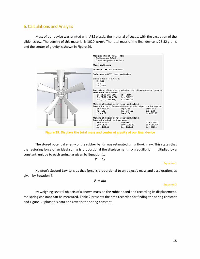
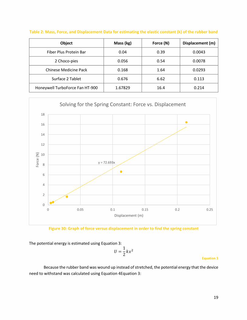
5.3 Powering the Device
Our device is powered by three rubber bands that are first knotted together and then stretched
to loop around the tail and propeller rod. By winding the propeller blades, we simultaneously twist the
rubber bands and store potential energy that is later converted to kinetic energy upon release. As the
propeller spins, it pushes back air that hits the glider and propels the device forward and generates lift.
Wheels are attached to the fuselage in order to help the device roll forward.
Figure 25: Assembling the rubber band and propeller
17
Figure 26: The blue arrow indicates how the air will be scooped by the propeller
Figure 27: The red arrow indicates the direction the propeller rotates
Figure 28: The blue arrow indicates the flow of air along the entire device; the white arrow shows the direction of travel
18
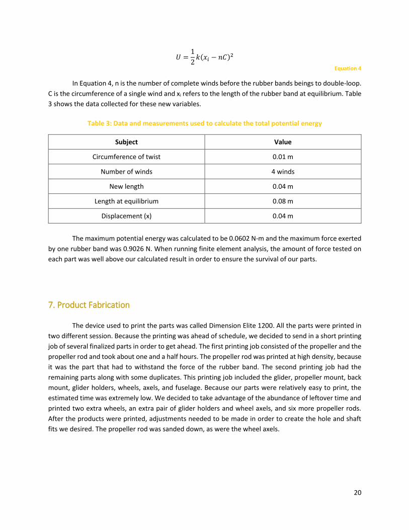
6. Calculations and Analysis
Most of our device was printed with ABS plastic, the material of Legos, with the exception of the
glider screw. The density of this material is 1020 kg/m3. The total mass of the final device is 73.32 grams
and the center of gravity is shown in Figure 29.
Figure 29: Displays the total mass and center of gravity of our final device
The stored potential energy of the rubber bands was estimated using Hook’s law. This states that
the restoring force of an ideal spring is proportional the displacement from equilibrium multiplied by a
constant, unique to each spring, as given by Equation 1.
𝐹 = 𝑘𝑥 Equation 1
Newton’s Second Law tells us that force is proportional to an object’s mass and acceleration, as
given by Equation 2.
𝐹 = 𝑚𝑎 Equation 2
By weighing several objects of a known mass on the rubber band and recording its displacement,
the spring constant can be measured. Table 2 presents the data recorded for finding the spring constant
and Figure 30 plots this data and reveals the spring constant.
19
Table 2: Mass, Force, and Displacement Data for estimating the elastic constant (k) of the rubber band
Object Mass (kg) Force (N) Displacement (m)
Fiber Plus Protein Bar 0.04 0.39 0.0043
2 Choco-pies 0.056 0.54 0.0078
Chinese Medicine Pack 0.168 1.64 0.0293
Surface 2 Tablet 0.676 6.62 0.113
Honeywell TurboForce Fan HT-900 1.67829 16.4 0.214
Figure 30: Graph of force versus displacement in order to find the spring constant
The potential energy is estimated using Equation 3:
𝑈 =1
2𝑘𝑥2
Equation 3
Because the rubber band was wound up instead of stretched, the potential energy that the device
need to withstand was calculated using Equation 4Equation 3:
y = 72.693x
0
2
4
6
8
10
12
14
16
18
0 0.05 0.1 0.15 0.2 0.25
Forc
e (N
)
Displacement (m)
Solving for the Spring Constant: Force vs. Displacement
20
𝑈 =1
2𝑘(𝑥𝑖 − 𝑛𝐶)2
Equation 4
In Equation 4, n is the number of complete winds before the rubber bands beings to double-loop.
C is the circumference of a single wind and xi refers to the length of the rubber band at equilibrium. Table
3 shows the data collected for these new variables.
Table 3: Data and measurements used to calculate the total potential energy
Subject Value
Circumference of twist 0.01 m
Number of winds 4 winds
New length 0.04 m
Length at equilibrium 0.08 m
Displacement (x) 0.04 m
The maximum potential energy was calculated to be 0.0602 N-m and the maximum force exerted
by one rubber band was 0.9026 N. When running finite element analysis, the amount of force tested on
each part was well above our calculated result in order to ensure the survival of our parts.
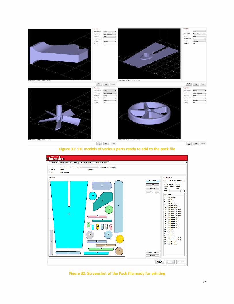
7. Product Fabrication
The device used to print the parts was called Dimension Elite 1200. All the parts were printed in
two different session. Because the printing was ahead of schedule, we decided to send in a short printing
job of several finalized parts in order to get ahead. The first printing job consisted of the propeller and the
propeller rod and took about one and a half hours. The propeller rod was printed at high density, because
it was the part that had to withstand the force of the rubber band. The second printing job had the
remaining parts along with some duplicates. This printing job included the glider, propeller mount, back
mount, glider holders, wheels, axels, and fuselage. Because our parts were relatively easy to print, the
estimated time was extremely low. We decided to take advantage of the abundance of leftover time and
printed two extra wheels, an extra pair of glider holders and wheel axels, and six more propeller rods.
After the products were printed, adjustments needed to be made in order to create the hole and shaft
fits we desired. The propeller rod was sanded down, as were the wheel axels.
21
Figure 31: STL models of various parts ready to add to the pack file
Figure 32: Screenshot of the Pack file ready for printing
22
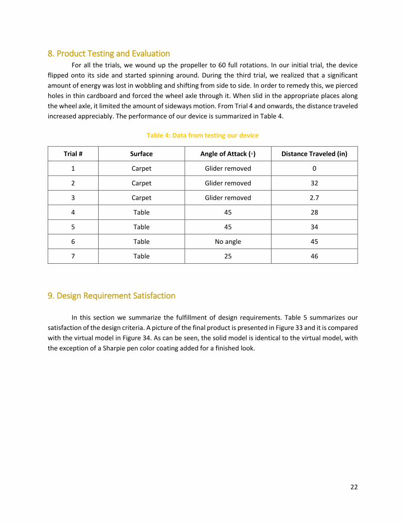
8. Product Testing and Evaluation For all the trials, we wound up the propeller to 60 full rotations. In our initial trial, the device
flipped onto its side and started spinning around. During the third trial, we realized that a significant
amount of energy was lost in wobbling and shifting from side to side. In order to remedy this, we pierced
holes in thin cardboard and forced the wheel axle through it. When slid in the appropriate places along
the wheel axle, it limited the amount of sideways motion. From Trial 4 and onwards, the distance traveled
increased appreciably. The performance of our device is summarized in Table 4.
Table 4: Data from testing our device
Trial # Surface Angle of Attack (◦) Distance Traveled (in)
1 Carpet Glider removed 0
2 Carpet Glider removed 32
3 Carpet Glider removed 2.7
4 Table 45 28
5 Table 45 34
6 Table No angle 45
7 Table 25 46
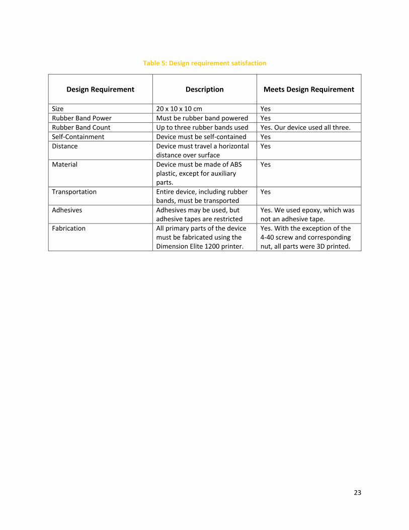
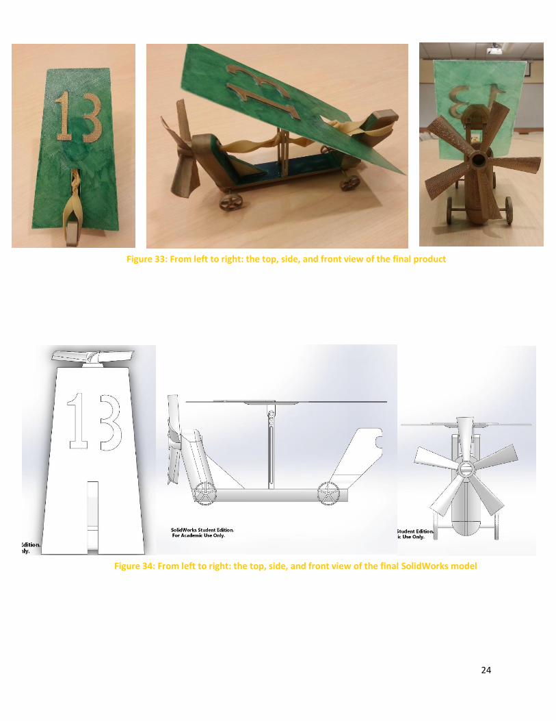
9. Design Requirement Satisfaction
In this section we summarize the fulfillment of design requirements. Table 5 summarizes our
satisfaction of the design criteria. A picture of the final product is presented in Figure 33 and it is compared
with the virtual model in Figure 34. As can be seen, the solid model is identical to the virtual model, with
the exception of a Sharpie pen color coating added for a finished look.
23
Table 5: Design requirement satisfaction
Design Requirement
Description
Meets Design Requirement
Size 20 x 10 x 10 cm Yes
Rubber Band Power Must be rubber band powered Yes
Rubber Band Count Up to three rubber bands used Yes. Our device used all three.
Self-Containment Device must be self-contained Yes
Distance Device must travel a horizontal distance over surface
Yes
Material Device must be made of ABS plastic, except for auxiliary parts.
Yes
Transportation Entire device, including rubber bands, must be transported
Yes
Adhesives Adhesives may be used, but adhesive tapes are restricted
Yes. We used epoxy, which was not an adhesive tape.
Fabrication All primary parts of the device must be fabricated using the Dimension Elite 1200 printer.
Yes. With the exception of the 4-40 screw and corresponding nut, all parts were 3D printed.
24
Figure 34: From left to right: the top, side, and front view of the final SolidWorks model
Figure 33: From left to right: the top, side, and front view of the final product
25
10. Conclusion
Through many design changes and much optimization, our three original design concepts transformed
into our completed product, Lucky. Lucky is a hybridization of the classic car and plane models. The
assembly consists of nine different parts made of ABS plastic and two auxiliary parts, a 4-40 screw and a
nut.
Lucky moves through the use of rubber bands attached to a propeller. The rubber bands are wound
up and released to spin the propeller. This generates airflow which propels the vehicle forward and also
hits the glider with the intention of creating lift. Using SolidWorks, the parts were designed to be
lightweight to maximize lift, but also strong enough to withstand the forces they would experience.
Through analysis of the rubber bands that would supply the energy, we were able to determine the spring
constant of the rubber bands, and thus the force applied on the parts. SolidWorks stress analyses were
performed to ensure the design would not break.
The parts were printed using the Dimension Elite 1200. Some of the printed parts such as the wheel
axles were sanded down to fit properly with adjacent parts. After assembly, Lucky underwent
performance tests. Here we found the most efficient angle of attack of the glider and also continued to
make adjustments to reduce friction between parts. With that, Lucky is functioning properly and all the
design requirements met.
Lessons learned from designing and manufacturing Lucky include the importance of tolerancing. We
were forced to sand the wheel axles to fit the fuselage and wheels correctly. In addition, we enlarged the
glider slit to give room for the rubber band. Had these been toleranced correctly, we would have saved
time in the assembly of the product. We also realized the importance of planning ahead and simple design.
On competition day, one of our rubber bands snapped, and we were fortunate to have a backup that
could easily replace the old one. During testing, the glider holders came loose after many trials, and we
were able to re-secure them with ease since they were easily accessible. In the worst case scenario where
crucial parts such as the propeller rod or the wheel axles broke, we would have plenty of backup parts
since they were simple prints that took little time to create.
In regards to our design, we learned that a glider is only useful if the propeller generates enough
airflow to generate lift off of it in the first place. This stresses the importance of analysis on SolidWorks:
had we known whether or not our device could lift in the first place, we could have made more meaningful
adjustments to our design. This project revealed to us the power of prototyping. The tremendous amount
we have learned from running a few trials on our device presents enormous potential for future design
iterations of Lucky.
26
11. References [1] http://www.hometrainingtools.com/a/rubberband-car-project, accessed 12/10/2014
[2] http://pbskids.org/designsquad/parentseducators/resources/rubber_band_car.html, accessed
12/10/2014
[3] http://alohaki.jugem.jp/?eid=474, accessed 12/10/2014
27
12. Appendix
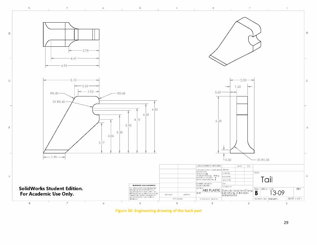
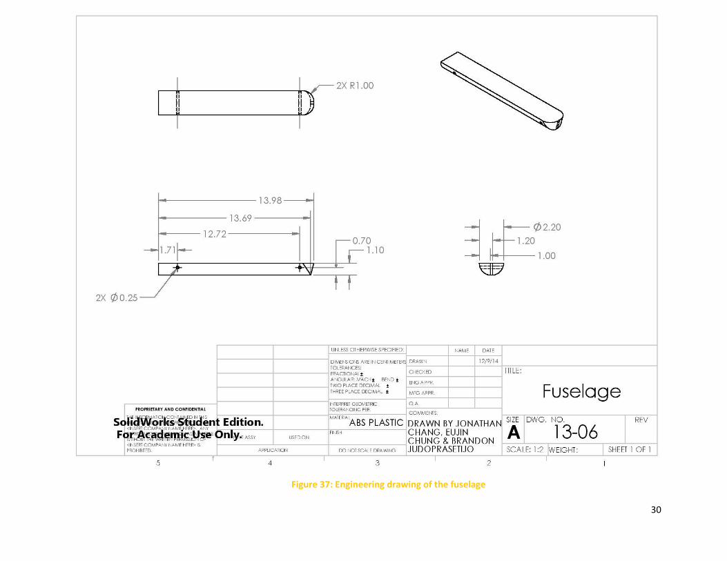
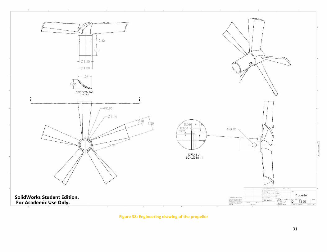
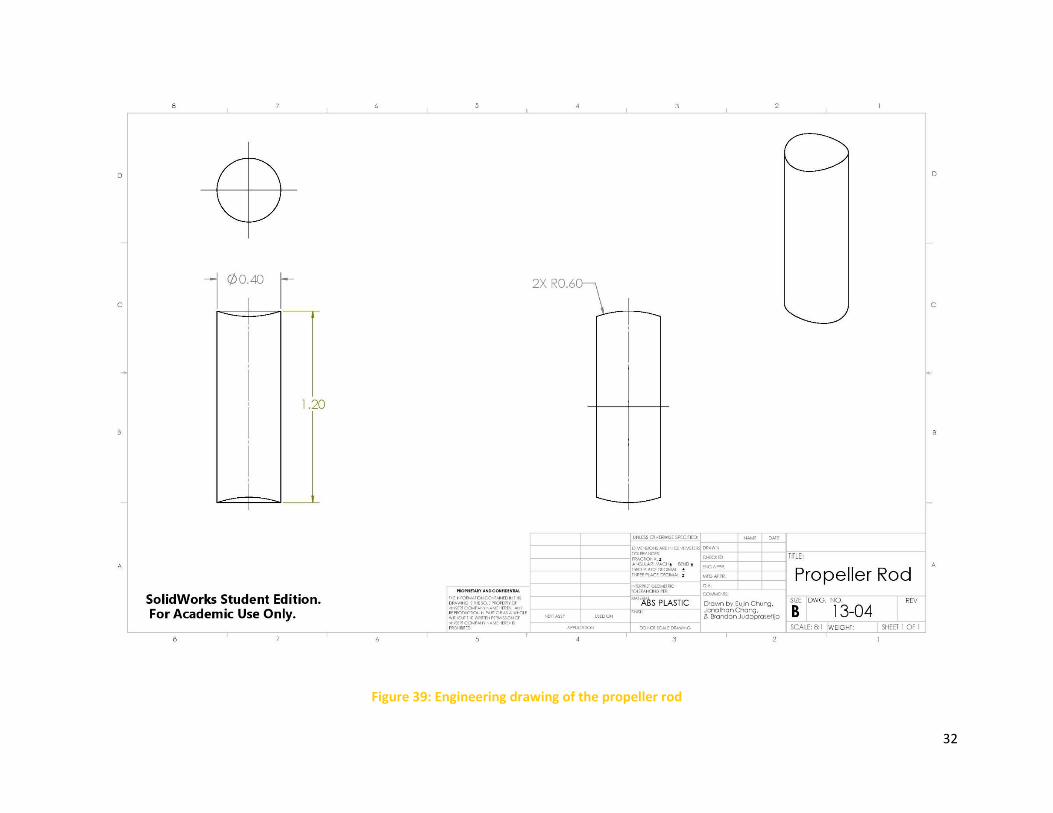
12.1 Part Drawings
The following show detailed engineering drawings of all the parts used in the final assembly. The wheel axles and wheels were duplicated but
the dimensions remained the same.
28
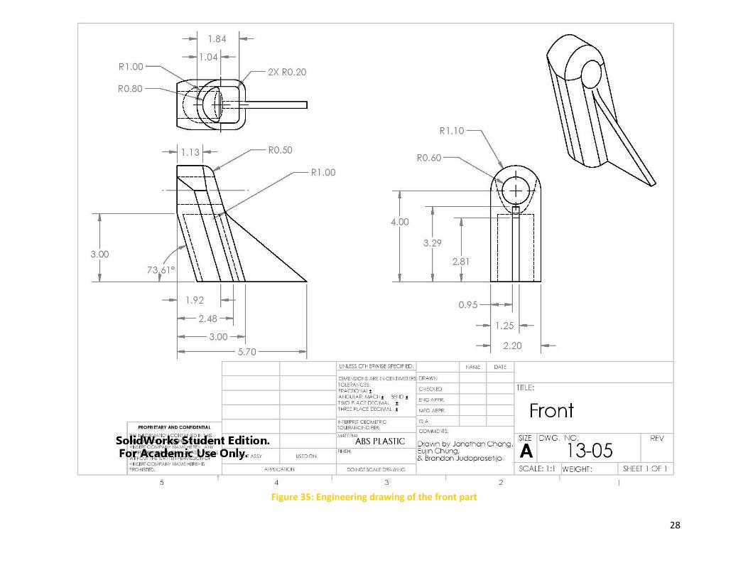
Figure 35: Engineering drawing of the front part
29
Figure 36: Engineering drawing of the back part
30
Figure 37: Engineering drawing of the fuselage
31
Figure 38: Engineering drawing of the propeller
32
Figure 39: Engineering drawing of the propeller rod
33
Figure 40: Engineering drawing of the glider part
34
Figure 41: Engineering drawing of the glider holder. Two duplicates are used in the final assembly.
35
Figure 42: Engineering drawing of the wheel part. Four duplicates were used in the final assembly.
36
Figure 43: Engineering drawing of the wheel axle part. Two duplicates were used in the final assembly.
37
Figure 44: Assembly drawing with BOM table
12.2 Assembly Drawing


