LTE Procedures 36213-930
80
3GPP TS 36.213 V9.3.0 (2010-09) Technical Specification 3 rd Generation Partnership Project; Technical Specification Group Radio Access Network; Evolved Universal Terrestrial Radio Access (E-UTRA); Physical layer procedures (Release 9) The present document has been developed within the 3 rd Generation Partnership Project (3GPP TM ) and may be further elaborated for the purposes of 3GPP. The present document has not been subject to any approval process by the 3GPP Organisational Partners and shall not be implemented. This Specific atio n is prov ided for futur e deve lopment work within 3GPP only . The Organis ational Partn ers accept no liabi lity for any use of this Specification. Specifications and reports for implementation of the 3GPP TM system should be obtained via the 3GPP Organisational Partners’ Publications Offices.
-
Upload
gaurav-goyal -
Category
Documents
-
view
222 -
download
0
Transcript of LTE Procedures 36213-930

7/29/2019 LTE Procedures 36213-930
http://slidepdf.com/reader/full/lte-procedures-36213-930 1/80
3GPP TS 36.213 V9.3.0 (2010-09)
Technical Specification
3rd Generation Partnership Project;Technical Specification Group Radio Access Network;Evolved Universal Terrestrial Radio Access (E-UTRA);
Physical layer procedures(Release 9)
The present document has been developed within the 3rd Generation Partnership Project (3GPP TM) and may be further elaborated for the purposes of 3GPP.
The present document has not been subject to any approval process by the 3GPP Organisational Partners and shall not be implemented.
This Specification is provided for future development work within 3GPP only. The Organisational Partners accept no liability for any use of thisSpecification.
Specifications and reports for implementation of the 3GPP TM system should be obtained via the 3GPP Organisational Partners’ Publications Offices.

7/29/2019 LTE Procedures 36213-930
http://slidepdf.com/reader/full/lte-procedures-36213-930 2/803GPP
KeywordsUMTS, radio, layer 1
3GPP
Postal address
3GPP support office address
650 Route des Lucioles – Sophia Antipolis
Valbonne – FranceTel.: +33 4 92 94 42 00 Fax: +33 4 93 65 47 16
Internet
http://www.3gpp.org
Copyright Notification
No part may be reproduced except as authorized by written permission.The copyright and the foregoing restriction extend to reproduction in all media.
© 2010, 3GPP Organizational Partners (ARIB, ATIS, CCSA, ETSI, TTA, TTC).All rights reserved.
UMTS™ is a Trade Mark of ETSI registered for the benefit of its members
3GPP™ is a Trade Mark of ETSI registered for the benefit of its Members and of the 3GPP Organizational PartnersLTE™ is a Trade Mark of ETSI currently being registered for the benefit of its Members and of the 3GPP
Organizational PartnersGSM® and the GSM logo are registered and owned by the GSM Association
3GPP TS 36.213 V9.3.0 (2010-09)2Release 9

7/29/2019 LTE Procedures 36213-930
http://slidepdf.com/reader/full/lte-procedures-36213-930 3/80
Contents
Foreword.................................................................................................................................................5
1 Scope....................................................................................................................................................6
2 References............................................................................................................................................6
3 Definitions, symbols, and abbreviations...............................................................................................73.1 Symbols..................................................................................................................................................................73.2 Abbreviations.........................................................................................................................................................7
4 Synchronisation procedures.................................................................................................................84.1 Cell search............................................................................................................................................................ ..8
4.2 Timing synchronisation..........................................................................................................................................84.2.1 Radio link monitoring.........................................................................................................................................8
4.2.2 Inter-cell synchronisation....................................................................................................................................84.2.3 Transmission timing adjustments........................................................................................................................8
5 Power control.......................................................................................................................................95.1 Uplink power control.............................................................................................................................................9
5.1.1 Physical uplink shared channel...........................................................................................................................95.1.1.1 UE behaviour...................................................................................................................................................9
5.1.1.2 Power headroom.............................................................................................................................................125.1.2 Physical uplink control channel........................................................................................................................12
5.1.2.1 UE behaviour.................................................................................................................................................125.1.3 Sounding Reference Symbol.............................................................................................................................14
5.1.3.1 UE behaviour.................................................................................................................................................145.2 Downlink power allocation .................................................................................................................................15
5.2.1 eNodeB Relative Narrowband TX Power restrictions................................................................................... ..16
6 Random access procedure..................................................................................................................176.1 Physical non-synchronized random access procedure.................................................................................... .....176.1.1 Timing 17
6.2 Random Access Response Grant.........................................................................................................................18
7 Physical downlink shared channel related procedures.......................................................................197.1 UE procedure for receiving the physical downlink shared channel.....................................................................197.1.1 Single-antenna port scheme................................................................................................................ ......... ...23
7.1.2 Transmit diversity scheme................................................................................................................... ......... ...247.1.3 Large delay CDD scheme.................................................................................................................... ......... ...24
7.1.4 Closed-loop spatial multiplexing scheme............................................................................................ ......... ...247.1.5 Multi-user MIMO scheme................................................................................................................................24
7.1.5A Dual layer scheme ............................................................................................................................... ........ .247.1.6 Resource allocation ................................................................................................................................ ........ .24
7.1.6.1 Resource allocation type 0.............................................................................................................................247.1.6.2 Resource allocation type 1.............................................................................................................................257.1.6.3 Resource allocation type 2.............................................................................................................................26
7.1.7 Modulation order and transport block size determination ............................................................... ......... ......27
7.1.7.1 Modulation order determination....................................................................................................................287.1.7.2 Transport block size determination............................................................................................................. ...28
7.1.7.2.1 Transport blocks not mapped to two-layer spatial multiplexing.................................................................297.1.7.2.2 Transport blocks mapped to two-layer spatial multiplexing.......................................................................35
7.1.7.2.3 Transport blocks mapped for DCI Format 1C............................................................................................357.1.7.3 Redundancy Version determination for Format 1C.................................................................................. .....36
7.2 UE procedure for reporting channel quality indication (CQI), precoding matrix indicator (PMI) and rank indication (RI)...........................................................................................................................................36
7.2.1 Aperiodic CQI/PMI/RI Reporting using PUSCH........................................................................................ .....39
7.2.2 Periodic CQI/PMI/RI Reporting using PUCCH......................................................................................... ......437.2.3 Channel quality indicator (CQI) definition.......................................................................................................497.2.4 Precoding Matrix Indicator (PMI) definition.................................................................................................. ..51
3GPP
3GPP TS 36.213 V9.3.0 (2010-09)3Release 9

7/29/2019 LTE Procedures 36213-930
http://slidepdf.com/reader/full/lte-procedures-36213-930 4/80
7.3 UE procedure for reporting ACK/NACK...................................................................................................... ......51
8 Physical uplink shared channel related procedures.............................................................................548.1 Resource Allocation for PDCCH DCI Format 0..................................................................................................578.2 UE sounding procedure........................................................................................................................................58
8.3 UE ACK/NACK procedure..................................................................................................................................608.4 UE PUSCH Hopping procedure...........................................................................................................................61
8.4.1 Type 1 PUSCH Hopping.................................................................................................................................628.4.2 Type 2 PUSCH Hopping.................................................................................................................................62
8.5 UE Reference Symbol procedure.........................................................................................................................638.6 Modulation order, redundancy version and transport block size determination............................................... ...63
8.6.1 Modulation order and redundancy version determination ...................................................................... ........638.6.2 Transport block size determination..................................................................................................................64
8.6.3 Control information MCS offset determination...............................................................................................658.7 UE Transmit Antenna Selection...........................................................................................................................67
9 Physical downlink control channel procedures...................................................................................679.1 UE procedure for determining physical downlink control channel assignment..................................................67
9.1.1 PDCCH Assignment Procedure................................................................................................................... ...679.1.2 PHICH Assignment Procedure........................................................................................................... ......... ...68
9.2 PDCCH validation for semi-persistent scheduling..............................................................................................69
10 Physical uplink control channel procedures.....................................................................................7010.1 UE procedure for determining physical uplink control channel assignment.....................................................7010.2 Uplink ACK/NACK timing...............................................................................................................................75
11 Physical multicast channel related procedures................................................................................7611.1 UE procedure for receiving the physical multicast channel...............................................................................76
11.2 UE procedure for receiving MCCH change notification...................................................................................76
Annex A (informative):
Change history......................................................................................77
3GPP
3GPP TS 36.213 V9.3.0 (2010-09)4Release 9

7/29/2019 LTE Procedures 36213-930
http://slidepdf.com/reader/full/lte-procedures-36213-930 5/80
Foreword
This Technical Specification (TS) has been produced by the 3rd Generation Partnership Project (3GPP).
The contents of the present document are subject to continuing work within the TSG and may change following formalTSG approval. Should the TSG modify the contents of this present document, it will be re-released by the TSG with an
identifying change of release date and an increase in version number as follows:
Version x.y.z
where:
x the first digit:
1 presented to TSG for information;
2 presented to TSG for approval;
3 or greater indicates TSG approved document under change control.
y the second digit is incremented for all changes of substance, i.e. technical enhancements, corrections,
updates, etc.
z the third digit is incremented when editorial only changes have been incorporated in the document.
3GPP
3GPP TS 36.213 V9.3.0 (2010-09)5Release 9

7/29/2019 LTE Procedures 36213-930
http://slidepdf.com/reader/full/lte-procedures-36213-930 6/80
1 Scope
The present document specifies and establishes the characteristics of the physicals layer procedures in the FDD andTDD modes of E-UTRA.
2 References
The following documents contain provisions which, through reference in this text, constitute provisions of the presentdocument.
• References are either specific (identified by date of publication, edition number, version number, etc.) or
non-specific.
• For a specific reference, subsequent revisions do not apply.
• For a non-specific reference, the latest version applies. In the case of a reference to a 3GPP document
(including a GSM document), a non-specific reference implicitly refers to the latest version of that documentin the same Release as the present document .
[1] 3GPP TR 21.905: “Vocabulary for 3GPP Specifications”
[2] 3GPP TS 36.201: “Evolved Universal Terrestrial Radio Access (E-UTRA); Physical Layer –
General Description”
[3] 3GPP TS 36.211: “Evolved Universal Terrestrial Radio Access (E-UTRA); Physical channels andmodulation”
[4] 3GPP TS 36.212: “Evolved Universal Terrestrial Radio Access (E-UTRA); Multiplexing andchannel coding”
[5] 3GPP TS 36.214: “Evolved Universal Terrestrial Radio Access (E-UTRA); Physical layer – Measurements”
[6] 3GPP TS 36.101: “Evolved Universal Terrestrial Radio Access (E-UTRA); User Equipment (UE)radio transmission and reception”
[7] 3GPP TS 36.104: “Evolved Universal Terrestrial Radio Access (E-UTRA); Base Station (BS)radio transmission and reception”
[8] 3GPP TS36.321, “Evolved Universal Terrestrial Radio Access (E-UTRA); Medium Access
Control (MAC) protocol specification”
[9] 3GPP TS36.423, “Evolved Universal Terrestrial Radio Access (E-UTRA); X2 ApplicationProtocol (X2AP)”
[10] 3GPP TS36.133, “Evolved Universal Terrestrial Radio Access (E-UTRA); Requirements for support of radio resource management”
[11] 3GPP TS36.331, “Evolved Universal Terrestrial Radio Access (E-UTRA); Radio ResourceControl (RRC) protocol specification”
3GPP
3GPP TS 36.213 V9.3.0 (2010-09)6Release 9

7/29/2019 LTE Procedures 36213-930
http://slidepdf.com/reader/full/lte-procedures-36213-930 7/80
3 Definitions, symbols, and abbreviations
3.1 Symbols
For the purposes of the present document, the following symbols apply:
f n System frame number as defined in [3]
sn Slot number within a radio frame as defined in [3]
DLRB N Downlink bandwidth configuration, expressed in units of
RBsc N as defined in [3]
ULRB N Uplink bandwidth configuration, expressed in units of
RBsc N as defined in [3]
ULsymb N Number of SC-FDMA symbols in an uplink slot as defined in [3]
RBsc N Resource block size in the frequency domain, expressed as a number of subcarriers as defined in
[3]
sT Basic time unit as defined in [3]
3.2 Abbreviations
For the purposes of the present document, the following abbreviations apply.
ACK AcknowledgementBCH Broadcast Channel
CCE Control Channel ElementCQI Channel Quality Indicator
CRC Cyclic Redundancy Check DAI Downlink Assignment Index
DCI Downlink Control InformationDL Downlink DL-SCH Downlink Shared Channel
DTX Discontinuous Transmission
EPRE Energy Per Resource Element
MCS Modulation and Coding Scheme NACK Negative Acknowledgement
PBCH Physical Broadcast Channel
PCFICH Physical Control Format Indicator ChannelPDCCH Physical Downlink Control Channel
PDSCH Physical Downlink Shared ChannelPHICH Physical Hybrid ARQ Indicator Channel
PMCH Physical Multicast Channel
PRACH Physical Random Access ChannelPRB Physical Resource Block PUCCH Physical Uplink Control Channel
PUSCH Physical Uplink Shared ChannelQoS Quality of Service
RBG Resource Block GroupRE Resource Element
RPF Repetition Factor RS Reference Signal
SIR Signal-to-Interference RatioSINR Signal to Interference plus Noise Ratio
SPS C-RNTI Semi-Persistent Scheduling C-RNTISR Scheduling Request
SRS Sounding Reference SymbolTA Time alignment
TTI Transmission Time IntervalUE User Equipment
3GPP
3GPP TS 36.213 V9.3.0 (2010-09)7Release 9

7/29/2019 LTE Procedures 36213-930
http://slidepdf.com/reader/full/lte-procedures-36213-930 8/80
UL Uplink UL-SCH Uplink Shared Channel
VRB Virtual Resource Block
4 Synchronisation procedures
4.1 Cell search
Cell search is the procedure by which a UE acquires time and frequency synchronization with a cell and detects the physical layer Cell ID of that cell. E-UTRA cell search supports a scalable overall transmission bandwidth
corresponding to 6 resource blocks and upwards.
The following signals are transmitted in the downlink to facilitate cell search: the primary and secondarysynchronization signals.
4.2 Timing synchronisation
4.2.1 Radio link monitoring
The downlink radio link quality of the serving cell shall be monitored by the UE for the purpose of indicating out-of-sync/in-sync status to higher layers.
In non-DRX mode operation, the physical layer in the UE shall every radio frame assess the radio link quality,evaluated over the previous time period defined in [10], against thresholds (Qout and Qin) defined by relevant tests in
[10].
In DRX mode operation, the physical layer in the UE shall at least once every DRX period assess the radio link quality,
evaluated over the previous time period defined in [10], against thresholds (Qout and Qin) defined by relevant tests in[10].
The physical layer in the UE shall in radio frames where the radio link quality is assessed indicate out-of-sync to higher layers when the radio link quality is worse than the threshold Qout. When the radio link quality is better than the
threshold Qin, the physical layer in the UE shall in radio frames where the radio link quality is assessed indicate in-sync
to higher layers.
4.2.2 Inter-cell synchronisation
No functionality is specified in this section in this release.
4.2.3 Transmission timing adjustments
Upon reception of a timing advance command, the UE shall adjust its uplink transmission timing for PUCCH/PUSCH/SRS. The timing advance command indicates the change of the uplink timing relative to the current
uplink timing as multiples of 16 sT . The start timing of the random access preamble is specified in [3].
In case of random access response, 11-bit timing advance command [8], T A, indicates N TA values by index values of T A
= 0, 1, 2, ..., 1282, where an amount of the time alignment is given by N TA = T A × 16. N TA is defined in [3].
In other cases, 6-bit timing advance command [8], T A, indicates adjustment of the current N TA value, N TA,old , to the new
N TA value, N TA,new, by index values of T A = 0, 1, 2,..., 63, where N TA,new = N TA,old + (T A −31)× 16. Here, adjustment of N TA
value by a positive or a negative amount indicates advancing or delaying the uplink transmission timing by a given
amount respectively.
For a timing advance command received on subframe n, the corresponding adjustment of the timing shall apply from
the beginning of subframe n+6 . When the UE’s uplink PUCCH/PUSCH/SRS transmissions in subframe n and subframen+1 are overlapped due to the timing adjustment, the UE shall transmit complete subframe n and not transmit the
overlapped part of subframe n+1.
3GPP
3GPP TS 36.213 V9.3.0 (2010-09)8Release 9

7/29/2019 LTE Procedures 36213-930
http://slidepdf.com/reader/full/lte-procedures-36213-930 9/80
If the received downlink timing changes and is not compensated or is only partly compensated by the uplink timingadjustment without timing advance command as specified in [10], the UE changes NTA accordingly.
5 Power controlDownlink power control determines the energy per resource element (EPRE). The term resource element energy
denotes the energy prior to CP insertion. The term resource element energy also denotes the average energy taken over all constellation points for the modulation scheme applied. Uplink power control determines the average power over a
SC-FDMA symbol in which the physical channel is transmitted.
5.1 Uplink power control
Uplink power control controls the transmit power of the different uplink physical channels.
A cell wide overload indicator (OI) and a High Interference Indicator (HII) to control UL interference are defined in [9].
5.1.1 Physical uplink shared channel
5.1.1.1 UE behaviour
The setting of the UE Transmit power PUSCH P for the physical uplink shared channel (PUSCH) transmission in
subframe i is defined by
)}()()()())((log10,min{)( TFO_PUSCHPUSCH10CMAXPUSCH i f i PL j j P i M P i P +∆+⋅++= α [dBm]
where,
• CMAX P is the configured UE transmitted power defined in [6]
• )(PUSCH i M is the bandwidth of the PUSCH resource assignment expressed in number of resource blocks valid
for subframe i.
• )(O_PUSCH j P is a parameter composed of the sum of a cell specific nominal component )(PUSCHO_NOMINAL_ j P
provided from higher layers for j=0 and 1 and a UE specific component )(O_UE_PUSCH j P provided by higher
layers for j=0 and 1. For PUSCH (re)transmissions corresponding to a semi-persistent grant then j=0 , for PUSCH (re)transmissions corresponding to a dynamic scheduled grant then j=1 and for PUSCH
(re)transmissions corresponding to the random access response grant then j=2. 0)2(O_UE_PUSCH
= P and
3 _ O_PREPUSCHO_NOMINAL_ )2( Msg PREAMBLE P P ∆+= , where the parameter
PREAMBLE_INITIAL_RECEIVED_TARGET_POWER [8] ( O_PRE P ) and 3 _ Msg PREAMBLE ∆ are signalled
from higher layers.
• For j =0 or 1, { }1,9.0,8.0,7.0,6.0,5.0,4.0,0∈α is a 3-bit cell specific parameter provided by higher layers.
For j=2, .1)( = jα
• PL is the downlink pathloss estimate calculated in the UE in dB and PL = referenceSignalPower – higher layer filtered RSRP, where referenceSignalPower is provided by higher layers and RSRP is defined in [5] and the
higher layer filter configuration is defined in [11]
• TF 10( ) 10log ((2 1) )S MPR K PUSCH
offset i β ⋅
∆ = − for 25.1=S K and 0 for 0=S K where S K is given by the UE specific parameter deltaMCS-Enabled provided by higher layers
3GPP
3GPP TS 36.213 V9.3.0 (2010-09)9Release 9

7/29/2019 LTE Procedures 36213-930
http://slidepdf.com/reader/full/lte-procedures-36213-930 10/80
o /CQI RE MPR O N = for control data sent via PUSCH without UL-SCH data and1
0
/C
r RE
r
K N −
=∑ for other
cases.
where C is the number of code blocks, r K is the size for code block r , CQI O is the number
of CQI bits including CRC bits andRE
N is the number of resource elements determined as
initial-PUSCH
symb N M N initial PUSCH
sc RE ⋅= −, where C , r K ,
initial PUSCH
sc M −and
initial-PUSCH
symb N are
defined in [4].
o PUSCH CQI
offset offset β β = for control data sent via PUSCH without UL-SCH data and 1 for other cases.
• PUSCHδ is a UE specific correction value, also referred to as a TPC command and is included in PDCCH with
DCI format 0 or jointly coded with other TPC commands in PDCCH with DCI format 3/3A whose CRC parity bits are scrambled with TPC-PUSCH-RNTI. The current PUSCH power control adjustment state is given by
)(i f which is defined by:
o )()1()( PUSCH PUSCH K ii f i f −+−= δ if accumulation is enabled based on the UE-specific parameter
Accumulation-enabled provided by higher layers or if the TPC command PUSCHδ is included in aPDCCH with DCI format 0 where the CRC is scrambled by the Temporary C-RNTI
where )(PUSCH PUSCH K i −δ was signalled on PDCCH with DCI format 0 or 3/3A on
subframe PUSCH K i − , and where )0( f is the first value after reset of accumulation.
The value of PUSCH K is
• For FDD, PUSCH K = 4
• For TDD UL/DL configurations 1-6, PUSCH K
is given in Table 5.1.1.1-1
• For TDD UL/DL configuration 0
o If the PUSCH transmission in subframe 2 or 7 is scheduled with a PDCCH
of DCI format 0 in which the LSB of the UL index is set to 1, PUSCH K = 7
o For all other PUSCH transmissions, PUSCH K
is given in Table 5.1.1.1-1.
The UE attempts to decode a PDCCH of DCI format 0 with the UE’s C-RNTI or SPS C-RNTI and a PDCCH of DCI format 3/3A with this UE’s TPC-PUSCH-RNTI in every
subframe except when in DRX
If DCI format 0 and DCI format 3/3A are both detected in the same subframe, then the UE
shall use the PUSCHδ provided in DCI format 0.
0PUSCH
=δ dB for a subframe where no TPC command is decoded or where DRX occurs or i is not an uplink subframe in TDD.
The PUSCHδ dB accumulated values signalled on PDCCH with DCI format 0 are given in
Table 5.1.1.1-2. If the PDCCH with DCI format 0 is validated as a SPS activation or release
PDCCH, then PUSCHδ is 0dB.
The PUSCHδ dB accumulated values signalled on PDCCH with DCI format 3/3A are one of
SET1 given in Table 5.1.1.1-2 or SET2 given in Table 5.1.1.1-3 as determined by the parameter TPC-Index provided by higher layers.
If UE has reached maximum power, positive TPC commands shall not be accumulated
If UE has reached minimum power, negative TPC commands shall not be accumulated
UE shall reset accumulation
• when O_UE_PUSCH P value is changed by higher layers
3GPP
3GPP TS 36.213 V9.3.0 (2010-09)10Release 9

7/29/2019 LTE Procedures 36213-930
http://slidepdf.com/reader/full/lte-procedures-36213-930 11/80
• when the UE receives random access response message
o )()( PUSCHPUSCH K ii f −= δ if accumulation is not enabled based on the UE-specific parameter
Accumulation-enabled provided by higher layers
where )(PUSCH PUSCH K i −δ was signalled on PDCCH with DCI format 0 on subframe
PUSCH K i −
The value of PUSCH K is
• For FDD, PUSCH K = 4
• For TDD UL/DL configurations 1-6, PUSCH K
is given in Table 5.1.1.1-1
• For TDD UL/DL configuration 0
o If the PUSCH transmission in subframe 2 or 7 is scheduled with a
PDCCHof DCI format 0 in which the LSB of the UL index is set to 1,
PUSCH K = 7
o For all other PUSCH transmissions, PUSCH K is given in Table 5.1.1.1-1.
The PUSCHδ dB absolute values signalled on PDCCH with DCI format 0 are given in Table
5.1.1.1-2. If the PDCCH with DCI format 0 is validated as a SPS activation or release
PDCCH, then PUSCHδ is 0dB.
)1()( −= i f i f for a subframe where no PDCCH with DCI format 0 is decoded or where
DRX occurs or i is not an uplink subframe in TDD.
o For both types of )(∗ f (accumulation or current absolute) the first value is set as follows:
If O_UE_PUSCH P value is changed by higher layers,
• ( )0 0 f =
Else
• 2)0( msg rampup P f δ +∆=
o where 2msg δ is the TPC command indicated in the random access
response, see Section 6.2, and
o rampup P ∆ is provided by higher layers and corresponds to the total power
ramp-up from the first to the last preamble
Table 5.1.1.1-1 PUSCH K for TDD configuration 0-6
TDD UL/DLConfiguratio
n
subframe number i
0 1 2 3 4 5 6 7 8 9
0 - - 6 7 4 - - 6 7 4
1 - - 6 4 - - - 6 4 -
2 - - 4 - - - - 4 - -
3 - - 4 4 4 - - - - -
4 - - 4 4 - - - - - -
5 - - 4 - - - - - - -
3GPP
3GPP TS 36.213 V9.3.0 (2010-09)11Release 9

7/29/2019 LTE Procedures 36213-930
http://slidepdf.com/reader/full/lte-procedures-36213-930 12/80
6 - - 7 7 5 - - 7 7 -
Table 5.1.1.1-2: Mapping of TPC Command Field in DCI format 0/3 to absolute and accumulated
PUSCHδ values.
TPC CommandField in
DCI format 0/3
Accumulated
PUSCHδ [dB]Absolute PUSCHδ [dB]
only DCI format 0
0 -1 -4
1 0 -1
2 1 1
3 3 4
Table 5.1.1.1-3: Mapping of TPC Command Field in DCI format 3A to accumulated PUSCHδ values.
TPC Command Field inDCI format 3A
Accumulated PUSCHδ [dB]
0 -1
1 1
5.1.1.2 Power headroom
The UE power headroom PH valid for subframe i is defined by
{ }CMAX 10 PUSCH O_PUSCH TF( ) 10log ( ( )) ( ) ( ) ( ) ( ) PH i P M i P j j PL i f iα = − + + ⋅ + ∆ + [dB]
where, CMAX P , )(PUSCH i M , )(O_PUSCH j P , )( jα , PL, )(TF i∆ and )(i f are defined in section 5.1.1.1.
The power headroom shall be rounded to the closest value in the range [40; -23] dB with steps of 1 dB and is delivered
by the physical layer to higher layers.
5.1.2 Physical uplink control channel
5.1.2.1 UE behaviour
The setting of the UE Transmit power PUCCH P for the physical uplink control channel (PUCCH) transmission in
subframe i is defined by
( ) ( ) ( ) ( ){ }i g F nnh PL P P i P HARQCQI +∆+++= F_PUCCH0_PUCCHCMAXPUCCH ,,min [dBm]
where
• CMAX P is the configured UE transmitted power defined in [6]
• The parameter F_PUCCH ( ) F ∆ is provided by higher layers. Each F_PUCCH ( ) F ∆ value corresponds to a PUCCH
format ( F ) relative to PUCCH format 1a, where each PUCCH format ( F ) is defined in Table 5.4-1 [3].
3GPP
3GPP TS 36.213 V9.3.0 (2010-09)12Release 9

7/29/2019 LTE Procedures 36213-930
http://slidepdf.com/reader/full/lte-procedures-36213-930 13/80
• ( ),CQI HARQh n n is a PUCCH format dependent value, where CQI n corresponds to the number of information
bits for the channel quality information defined in section 5.2.3.3 in [4] and HARQn is the number of HARQ
bits.
o For PUCCH format 1,1a and 1b 0, = HARQCQI nnh
o For PUCCH format 2, 2a, 2b and normal cyclic prefix
( )
≥
=
otherwise0
4if 4
log10, 10 CQI
CQI
HARQCQI
nn
nnh
o For PUCCH format 2 and extended cyclic prefix
( ) 1010log if 4, 4
0 otherwise
CQI HARQCQI HARQ
CQI HARQ
n nn n
h n n
+ + ≥ =
• O_PUCCH P
is a parameter composed of the sum of a cell specific parameter PUCCHO_NOMINAL_ P
provided byhigher layers and a UE specific component O_UE_PUCCH P provided by higher layers.
• PUCCHδ is a UE specific correction value, also referred to as a TPC command, included in a PDCCH with DCI
format 1A/1B/1D/1/2A/2/2B or sent jointly coded with other UE specific PUCCH correction values on a
PDCCH with DCI format 3/3A whose CRC parity bits are scrambled with TPC-PUCCH-RNTI.
o The UE attempts to decode a PDCCH of DCI format 3/3A with the UE’s TPC-PUCCH-RNTI and one
or several PDCCHs of DCI format 1A/1B/1D/1/2A/2/2B with the UE’s C-RNTI or SPS C-RNTI on
every subframe except when in DRX.
o If the UE decodes a PDCCH with DCI format 1A/1B/1D/1/2A/2/2B and the corresponding detected
RNTI equals the C-RNTI or SPS C-RNTI of the UE, the UE shall use the PUCCHδ provided in that
PDCCH.
else
if the UE decodes a PDCCH with DCI format 3/3A, the UE shall use the PUCCHδ provided
in that PDCCH
else the UE shall set PUCCHδ = 0 dB.
o
1
0
( ) ( 1) ( ) M
PUCCH mm
g i g i i k δ −
== − + −∑ where )(i g is the current PUCCH power control adjustment state
and where ( )0 g is the first value after reset.
For FDD, 1= M and 40 =k .
For TDD, values of M and mk are given in Table 10.1-1.
The PUCCHδ dB values signalled on PDCCH with DCI format 1A/1B/1D/1/2A/2/2B are
given in Table 5.1.2.1-1. If the PDCCH with DCI format 1/1A/2/2A/2B is validated as an
SPS activation PDCCH, or the PDCCH with DCI format 1A is validated as an SPS release
PDCCH, then PUCCHδ is 0dB.
The PUCCHδ dB values signalled on PDCCH with DCI format 3/3A are given in Table
5.1.2.1-1 or in Table 5.1.2.1-2 as semi-statically configured by higher layers.
If O_UE_PUCCH P
value is changed by higher layers,
• ( )0 0 g =
3GPP
3GPP TS 36.213 V9.3.0 (2010-09)13Release 9

7/29/2019 LTE Procedures 36213-930
http://slidepdf.com/reader/full/lte-procedures-36213-930 14/80
Else
• 2(0) rampup msg g P δ = ∆ +
o where 2msg δ is the TPC command indicated in the random access
response, see Section 6.2 and
o rampup P ∆ is the total power ramp-up from the first to the last preamble
provided by higher layers
If UE has reached maximum power, positive TPC commands shall not be accumulated
If UE has reached minimum power, negative TPC commands shall not be accumulated
UE shall reset accumulation
• when O_UE_PUCCH P value is changed by higher layers
• when the UE receives a random access response message
( ) ( 1) g i g i= − if i is not an uplink subframe in TDD.
Table 5.1.2.1-1: Mapping of TPC Command Field in DCI format 1A/1B/1D/1/2A/2B/2/3 to PUCCHδ
values.
TPC Command Field inDCI format
1A/1B/1D/1/2A/2B/2/3PUCCHδ [dB]
0 -1
1 0
2 1
3 3
Table 5.1.2.1-2: Mapping of TPC Command Field in DCI format 3A to PUCCHδ values.
TPC Command Field inDCI format 3A PUCCHδ [dB]
0 -1
1 1
5.1.3 Sounding Reference Symbol
5.1.3.1 UE behaviour
The setting of the UE Transmit power SRS P for the Sounding Reference Symbol transmitted on subframe i is defined by
SRS CMAX SRS_OFFSET 10 SRS O_PUSCH( ) min{ , 10log ( ) ( ) ( ) ( )} P i P P M P j j PL f iα = + + + ⋅ + [dBm]
where
• CMAX P is the configured UE transmitted power defined in [6]
• For 1.25S K = , SRS_OFFSET P is a 4-bit UE specific parameter semi-statically configured by higher layers with
1dB step size in the range [-3, 12] dB.
• For 0=S K , SRS_OFFSET P is a 4-bit UE specific parameter semi-statically configured by higher layers with 1.5
dB step size in the range [-10.5,12] dB
3GPP
3GPP TS 36.213 V9.3.0 (2010-09)14Release 9

7/29/2019 LTE Procedures 36213-930
http://slidepdf.com/reader/full/lte-procedures-36213-930 15/80
• SRS M is the bandwidth of the SRS transmission in subframe i expressed in number of resource blocks.
• )(i f is the current power control adjustment state for the PUSCH, see Section 5.1.1.1.
• )(O_PUSCH j P and )( jα are parameters as defined in Section 5.1.1.1, where 1= j .
5.2 Downlink power allocation
The eNodeB determines the downlink transmit energy per resource element.
A UE may assume downlink cell-specific RS EPRE is constant across the downlink system bandwidth and constantacross all subframes until different cell-specific RS power information is received. The downlink reference-signal
EPRE can be derived from the downlink reference-signal transmit power given by the parameter Reference-signal-
power provided by higher layers. The downlink reference-signal transmit power is defined as the linear average over the
power contributions (in [W]) of all resource elements that carry cell-specific reference signals within the operatingsystem bandwidth.
The ratio of PDSCH EPRE to cell-specific RS EPRE among PDSCH REs (not applicable to PDSCH REs with zero
EPRE) for each OFDM symbol is denoted by either A ρ or B ρ according to the OFDM symbol index as given by Table
5.2-2. In addition, A ρ and B ρ are UE-specific.
For a UE in transmission mode 8 when UE-specific RSs are not present in the PRBs upon which the corresponding
PDSCH is mapped or in transmission modes 1 – 7, the UE may assume that for 16 QAM, 64 QAM, spatial multiplexingwith more than one layer or for PDSCH transmissions associated with the multi-user MIMO transmission scheme,
A ρ is equal to )2(log10 10offset- power ++ A P δ [dB] when the UE receives a PDSCH data transmission using
precoding for transmit diversity with 4 cell-specific antenna ports according to Section 6.3.4.3 of [3];
A
ρ is equal to A
P
+offset- power δ
[dB] otherwise
where offset- power δ is 0 dB for all PDSCH transmission schemes except multi-user MIMO and where A P is a UE specific
parameter provided by higher layers.
For transmission mode 7, if UE-specific RSs are present in the PRBs upon which the corresponding PDSCH is mapped,the ratio of PDSCH EPRE to UE-specific RS EPRE within each OFDM symbol containing UE-specific RSs shall be a
constant, and that constant shall be maintained over all the OFDM symbols containing the UE-specific RSs in thecorresponding PRBs. In addition, the UE may assume that for 16QAM or 64QAM, this ratio is 0 dB.
For transmission mode 8, if UE-specific RSs are present in the PRBs upon which the corresponding PDSCH is mapped,
the UE may assume the ratio of PDSCH EPRE to UE-specific RS EPRE within each OFDM symbol containing UE-
specific RSs is 0 dB.
A UE may assume that downlink positioning reference signal EPRE is constant across the positioning reference signal
bandwidth and across all OFDM symbols that contain positioning reference signals in a given positioning referencesignal occasion [10].
The cell-specific ratio A B ρ ρ / is given by Table 5.2-1 according to cell-specific parameter B P signalled by higher
layers and the number of configured eNodeB cell specific antenna ports.
3GPP
3GPP TS 36.213 V9.3.0 (2010-09)15Release 9

7/29/2019 LTE Procedures 36213-930
http://slidepdf.com/reader/full/lte-procedures-36213-930 16/80
Table 5.2-1: The cell-specific ratio A B ρ ρ / for 1, 2, or 4 cell specific antenna ports
B P A B ρ ρ /
One Antenna Port Two and Four Antenna Ports
0 1 5/4
1 4/5 1
2 3/5 3/43 2/5 1/2
For PMCH with 16QAM or 64QAM, the UE may assume that the ratio of PMCH EPRE to MBSFN RS EPRE is equalto 0 dB.
Table 5.2-2: OFDM symbol indices within a slot where the ratio of the corresponding PDSCH EPRE to
the cell-specific RS EPRE is denoted by A ρ or B ρ
Number of antenna
ports
OFDM symbol indices within a slot where
the ratio of the corresponding PDSCH
EPRE to the cell-specific RS EPRE is
denoted by A ρ
OFDM symbol indices within a slot where
the ratio of the corresponding PDSCH
EPRE to the cell-specific RS EPRE is
denoted by B ρ
Normal cyclic prefix Extended cyclic
prefix
Normal cyclic prefix Extended cyclic
prefix
One or two 1, 2, 3, 5, 6 1, 2, 4, 5 0, 4 0, 3
Four 2, 3, 5, 6 2, 4, 5 0, 1, 4 0, 1, 3
5.2.1 eNodeB Relative Narrowband TX Power restrictions
The determination of reported Relative Narrowband TX Power indication ( ) PRBn RNTP is defined as follows:
≤
=madeis
)( of limitupper about the promisenoif 1
)(if 0
)(
)(
max_
)(
max_
p
nom
PRB A
threshold p
nom
PRB A
PRB
E
n E
RNTP E
n E
n RNTP
where )( PRB A n E is the maximum intended EPRE of UE-specific PDSCH REs in OFDM symbols not containing RS
in this physical resource block on antenna port p in the considered future time interval; PRBn is the physical resource
block number 1,...,0 −= DL RB PRB N n ; threshold RNTP takes on one of the following values
{ }3,2,1,0,1,2,3,4,5,6,7,8,9,10,11, +++−−−−−−−−−−−∞−∈threshold RNTP [dB] and
RB
SC
DL
RB
p
p
nom N N
f P
E ⋅
∆⋅
=
1)(
max
)(
max_
where)(
max
p P is the base station maximum output power described in [7], and f ∆ , DL
RB N andRB
SC N are defined in [3].
3GPP
3GPP TS 36.213 V9.3.0 (2010-09)16Release 9

7/29/2019 LTE Procedures 36213-930
http://slidepdf.com/reader/full/lte-procedures-36213-930 17/80
6 Random access procedure
Prior to initiation of the non-synchronized physical random access procedure, Layer 1 shall receive the followinginformation from the higher layers:
1. Random access channel parameters (PRACH configuration and frequency position)
2. Parameters for determining the root sequences and their cyclic shifts in the preamble sequence set for the cell
(index to logical root sequence table, cyclic shift ( CS N ), and set type (unrestricted or restricted set))
6.1 Physical non-synchronized random access procedure
From the physical layer perspective, the L1 random access procedure encompasses the transmission of random access
preamble and random access response. The remaining messages are scheduled for transmission by the higher layer onthe shared data channel and are not considered part of the L1 random access procedure. A random access channel
occupies 6 resource blocks in a subframe or set of consecutive subframes reserved for random access preambletransmissions. The eNodeB is not prohibited from scheduling data in the resource blocks reserved for random access
channel preamble transmission.
The following steps are required for the L1 random access procedure:
1. Layer 1 procedure is triggered upon request of a preamble transmission by higher layers.
2. A preamble index, a target preamble received power (PREAMBLE_RECEIVED_TARGET_POWER), a
corresponding RA-RNTI and a PRACH resource are indicated by higher layers as part of the request.
3. A preamble transmission power PPRACH is determined as
PPRACH = min{ CMAX P , PREAMBLE_RECEIVED_TARGET_POWER + PL}_[dBm], where CMAX P is the
configured UE transmitted power defined in [6] and PL is the downlink pathloss estimate calculated in theUE.
4. A preamble sequence is selected from the preamble sequence set using the preamble index.
5. A single preamble is transmitted using the selected preamble sequence with transmission power PPRACH on the
indicated PRACH resource.
6. Detection of a PDCCH with the indicated RA-RNTI is attempted during a window controlled by higher layers
(see [8], clause 5.1.4). If detected, the corresponding DL-SCH transport block is passed to higher layers. Thehigher layers parse the transport block and indicate the 20-bit uplink grant to the physical layer, which is
processed according to section 6.2.
6.1.1 Timing
For the L1 random access procedure, UE’s uplink transmission timing after a random access preamble transmission isas follows.
a. If a PDCCH with associated RA-RNTI is detected in subframe n, and the corresponding DL-SCH
transport block contains a response to the transmitted preamble sequence, the UE shall, according to
the information in the response, transmit an UL-SCH transport block in the first subframe 1k n + ,
61 ≥k , if the UL delay field in section 6.2 is set to zero where 1k n + is the first available UL subframe
for PUSCH transmission. The UE shall postpone the PUSCH transmission to the next available UL
subframe after 1k n + if the field is set to 1.
b. If a random access response is received in subframe n, and the corresponding DL-SCH transport
block does not contain a response to the transmitted preamble sequence, the UE shall, if requested by
higher layers, be ready to transmit a new preamble sequence no later than in subframe 5n + .
c. If no random access response is received in subframe n, where subframe n is the last subframe of therandom access response window, the UE shall, if requested by higher layers, be ready to transmit a
new preamble sequence no later than in subframe 4n + .
3GPP
3GPP TS 36.213 V9.3.0 (2010-09)17Release 9

7/29/2019 LTE Procedures 36213-930
http://slidepdf.com/reader/full/lte-procedures-36213-930 18/80
In case a random access procedure is initiated by a PDCCH order in subframe n, the UE shall, if requested by higher
layers, transmit random access preamble in the first subframe 2n k + , 2 6k ≥ , where a PRACH resource is available.
6.2 Random Access Response GrantThe higher layers indicate the 20-bit UL Grant to the physical layer, as defined in [8]. This is referred to the Random
Access Response Grant in the physical layer. The content of these 20 bits starting with the MSB and ending with theLSB are as follows:
- Hopping flag – 1 bit
- Fixed size resource block assignment – 10 bits
- Truncated modulation and coding scheme – 4 bits
- TPC command for scheduled PUSCH – 3 bits
- UL delay – 1 bit
- CQI request – 1 bit
The UE shall perform PUSCH frequency hopping if the single bit frequency hopping (FH) field in a correspondingRandom Access Response Grant is set as 1, otherwise no PUSCH frequency hopping is performed. When the hopping
flag is set, the UE shall perform PUSCH hopping as indicated via the fixed size resource block assignment detailed below,
The fixed size resource block assignment field is interpreted as follows:
if 44ULRB ≤ N
Truncate the fixed size resource block assignment to its b least significant bits, where
( )( ) 2/1log ULRB
ULRB2 +⋅= N N b , and interpret the truncated resource block assignment according to the rules for a
regular DCI format 0
else
Insert b most significant bits with value set to ‘0’ after the N UL_hop hopping bits in the fixed size resource block assignment, where the number of hopping bits N UL_hop is zero when the hopping flag bit is not set to 1, and is defined
in Table 8.4-1 when the hopping flag bit is set to 1, and ( )( )
−+⋅= 102/1log
ULRB
ULRB2 N N b , and interpret the
expanded resource block assignment according to the rules for a regular DCI format 0
end if
The truncated modulation and coding scheme field is interpreted such that the modulation and coding schemecorresponding to the Random Access Response grant is determined from MCS indices 0 through 15 in Table 8.6.1-1.
The TPC command 2msg δ shall be used for setting the power of the PUSCH, and is interpreted according to Table 6.2-
1.
3GPP
3GPP TS 36.213 V9.3.0 (2010-09)18Release 9
7/29/2019 LTE Procedures 36213-930
http://slidepdf.com/reader/full/lte-procedures-36213-930 19/80
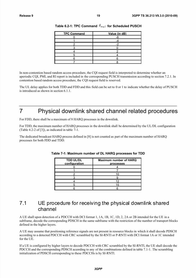
Table 6.2-1: TPC Command 2msg δ for Scheduled PUSCH
TPC Command Value (in dB)
0 -6
1 -4
2 -2
3 04 2
5 4
6 6
7 8
In non-contention based random access procedure, the CQI request field is interpreted to determine whether anaperiodic CQI, PMI, and RI report is included in the corresponding PUSCH transmission according to section 7.2.1. In
contention based random access procedure, the CQI request field is reserved.
The UL delay applies for both TDD and FDD and this field can be set to 0 or 1 to indicate whether the delay of PUSCH
is introduced as shown in section 6.1.1.
7 Physical downlink shared channel related procedures
For FDD, there shall be a maximum of 8 HARQ processes in the downlink.
For TDD, the maximum number of HARQ processes in the downlink shall be determined by the UL/DL configuration
(Table 4.2-2 of [3]), as indicated in table 7-1.
The dedicated broadcast HARQ process defined in [8] is not counted as part of the maximum number of HARQ processes for both FDD and TDD.
Table 7-1: Maximum number of DL HARQ processes for TDD
TDD UL/DLconfiguration
Maximum number of HARQprocesses
0 4
1 7
2 10
3 9
4 12
5 15
6 6
7.1 UE procedure for receiving the physical downlink sharedchannel
A UE shall upon detection of a PDCCH with DCI format 1, 1A, 1B, 1C, 1D, 2, 2A or 2B intended for the UE in asubframe, decode the corresponding PDSCH in the same subframe with the restriction of the number of transport blocks
defined in the higher layers.
A UE may assume that positioning reference signals are not present in resource blocks in which it shall decode PDSCH
according to a detected PDCCH with CRC scrambled by the SI-RNTI or P-RNTI with DCI format 1A or 1C intendedfor the UE.
If a UE is configured by higher layers to decode PDCCH with CRC scrambled by the SI-RNTI, the UE shall decode thePDCCH and the corresponding PDSCH according to any of the combinations defined in table 7.1-1. The scrambling
initialization of PDSCH corresponding to these PDCCHs is by SI-RNTI.
3GPP
3GPP TS 36.213 V9.3.0 (2010-09)19Release 9

7/29/2019 LTE Procedures 36213-930
http://slidepdf.com/reader/full/lte-procedures-36213-930 20/80
Table 7.1-1: PDCCH and PDSCH configured by SI-RNTI
DCI format Search Space Transmission scheme of PDSCH corresponding to PDCCH
DCI format 1C Common If the number of PBCH antenna ports is one, Single-antennaport, port 0 is used, otherwise Transmit diversity.
DCI format 1A Common If the number of PBCH antenna ports is one, Single-antennaport, port 0 is used, otherwise Transmit diversity
If a UE is configured by higher layers to decode PDCCH with CRC scrambled by the P-RNTI, the UE shall decode thePDCCH and the corresponding PDSCH according to any of the combinations defined in table 7.1-2. The scrambling
initialization of PDSCH corresponding to these PDCCHs is by P-RNTI.
Table 7.1-2: PDCCH and PDSCH configured by P-RNTI
DCI format Search Space Transmission scheme of PDSCH corresponding to PDCCH
DCI format 1C Common If the number of PBCH antenna ports is one, Single-antennaport, port 0 is used (see subclause 7.1.1), otherwise Transmitdiversity (see subclause 7.1.2)
DCI format 1A Common If the number of PBCH antenna ports is one, Single-antennaport, port 0 is used (see subclause 7.1.1), otherwise Transmitdiversity (see subclause 7.1.2)
If a UE is configured by higher layers to decode PDCCH with CRC scrambled by the RA-RNTI, the UE shall decode
the PDCCH and the corresponding PDSCH according to any of the combinations defined in table 7.1-3. The scramblinginitialization of PDSCH corresponding to these PDCCHs is by RA-RNTI.
When RA-RNTI and either C-RNTI or SPS C-RNTI are assigned in the same subframe, UE is not required to decode aPDSCH indicated by a PDCCH with a CRC scrambled by C-RNTI or SPS C-RNTI.
Table 7.1-3: PDCCH and PDSCH configured by RA-RNTI
DCI format Search Space Transmission scheme of PDSCH corresponding to PDCCH
DCI format 1C Common If the number of PBCH antenna ports is one, Single-antennaport, port 0 is used (see subclause 7.1.1), otherwise Transmitdiversity (see subclause 7.1.2)
DCI format 1A Common If the number of PBCH antenna ports is one, Single-antennaport, port 0 is used (see subclause 7.1.1), otherwise Transmitdiversity (see subclause 7.1.2)
The UE is semi-statically configured via higher layer signalling to receive PDSCH data transmissions signalled viaPDCCH according to one of eight transmission modes, denoted mode 1 to mode 8.
For frame structure type 1,
-the UE is not expected to receive PDSCH resource blocks transmitted on antenna port 5 in any subframe inwhich the number of OFDM symbols for PDCCH with normal CP is equal to four;
-the UE is not expected to receive PDSCH resource blocks transmitted on antenna port 5, 7, or 8 in the twoPRBs to which a pair of VRBs is mapped if either one of the two PRBs overlaps in frequency with a
transmission of either PBCH or primary or secondary synchronisation signals in the same subframe;
- the UE is not expected to receive PDSCH resource blocks transmitted on antenna port 7 for which
distributed VRB resource allocation is assigned.
- The UE may skip decoding the transport block(s) if it does not receive all assigned PDSCH resource blocks.
If the UE skips decoding, the physical layer indicates to higher layer that the transport block(s) are notsuccessfully decoded.
For frame structure type 2,
3GPP
3GPP TS 36.213 V9.3.0 (2010-09)20Release 9

7/29/2019 LTE Procedures 36213-930
http://slidepdf.com/reader/full/lte-procedures-36213-930 21/80
- the UE is not expected to receive PDSCH resource blocks transmitted on antenna port 5 in any subframe inwhich the number of OFDM symbols for PDCCH with normal CP is equal to four;
- the UE is not expected to receive PDSCH resource blocks transmitted on antenna port 5 in the two PRBs towhich a pair of VRBs is mapped if either one of the two PRBs overlaps in frequency with a transmission
of PBCH in the same subframe;
- the UE is not expected to receive PDSCH resource blocks transmitted on antenna port 7 or 8 in the twoPRBs to which a pair of VRBs is mapped if either one of the two PRBs overlaps in frequency with a
transmission of primary or secondary synchronisation signals in the same subframe;
- with normal CP configuration, the UE is not expected to receive PDSCH on antenna port 5 for whichdistributed VRB resource allocation is assigned in the special subframe with configuration #1 or #6;
- the UE is not expected to receive PDSCH on antenna port 7 for which distributed VRB resource allocationis assigned.
- The UE may skip decoding the transport block(s) if it does not receive all assigned PDSCH resource blocks.
If the UE skips decoding, the physical layer indicates to higher layer that the transport block(s) are notsuccessfully decoded.
If a UE is configured by higher layers to decode PDCCH with CRC scrambled by the C-RNTI, the UE shall decode the
PDCCH and any corresponding PDSCH according to the respective combinations defined in table 7.1-5. Thescrambling initialization of PDSCH corresponding to these PDCCHs is by C-RNTI.
When a UE configured in transmission mode 3, 4 or 8 receives a DCI Format 1A assignment, it shall assume that thePDSCH transmission is associated with transport block 1 and that transport block 2 is disabled.
When a UE is configured in transmission mode 7, scrambling initialization of UE-specific reference signals
corresponding to these PDCCHs is by C-RNTI.
The UE does not support transmission mode 8 if extended cyclic prefix is used in the downlink.
3GPP
3GPP TS 36.213 V9.3.0 (2010-09)21Release 9

7/29/2019 LTE Procedures 36213-930
http://slidepdf.com/reader/full/lte-procedures-36213-930 22/80
Table 7.1-5: PDCCH and PDSCH configured by C-RNTI
Transmissionmode
DCI format Search Space Transmission scheme of PDSCHcorresponding to PDCCH
Mode 1 DCI format 1A Common andUE specific by C-RNTI
Single-antenna port, port 0 (see subclause7.1.1)
DCI format 1 UE specific by C-RNTI Single-antenna port, port 0 (see subclause7.1.1)
Mode 2 DCI format 1A Common andUE specific by C-RNTI
Transmit diversity (see subclause 7.1.2)
DCI format 1 UE specific by C-RNTI Transmit diversity (see subclause 7.1.2)
Mode 3 DCI format 1A Common andUE specific by C-RNTI
Transmit diversity (see subclause 7.1.2)
DCI format 2A UE specific by C-RNTI Large delay CDD (see subclause 7.1.3) or Transmit diversity (see subclause 7.1.2)
Mode 4 DCI format 1A Common andUE specific by C-RNTI
Transmit diversity (see subclause 7.1.2)
DCI format 2 UE specific by C-RNTI Closed-loop spatial multiplexing (seesubclause 7.1.4)or Transmit diversity (seesubclause 7.1.2)
Mode 5 DCI format 1A Common andUE specific by C-RNTI
Transmit diversity (see subclause 7.1.2)
DCI format 1D UE specific by C-RNTI Multi-user MIMO (see subclause 7.1.5)
Mode 6 DCI format 1A Common andUE specific by C-RNTI
Transmit diversity (see subclause 7.1.2)
DCI format 1B UE specific by C-RNTI Closed-loop spatial multiplexing (seesubclause 7.1.4) using a singletransmission layer
Mode 7 DCI format 1A Common andUE specific by C-RNTI
If the number of PBCH antenna ports isone, Single-antenna port, port 0 is used(see subclause 7.1.1), otherwise Transmitdiversity (see subclause 7.1.2)
DCI format 1 UE specific by C-RNTI Single-antenna port; port 5 (see subclause7.1.1)
Mode 8 DCI format 1A Common andUE specific by C-RNTI
If the number of PBCH antenna ports isone, Single-antenna port, port 0 is used(see subclause 7.1.1), otherwise Transmitdiversity (see subclause 7.1.2)
DCI format 2B UE specific by C-RNTI Dual layer transmission; port 7 and 8 (seesubclause 7.1.5A) or single-antenna port;port 7 or 8 (see subclause 7.1.1)
If a UE is configured by higher layers to decode PDCCH with CRC scrambled by the SPS C-RNTI, the UE shall
decode the PDCCH and any corresponding PDSCH according to the respective combinations defined in table 7.1-6.The same PDSCH related configuration applies in the case that a PDSCH is transmitted without a corresponding
PDCCH. The scrambling initialization of PDSCH corresponding to these PDCCHs and PDSCH without acorresponding PDCCH is by SPS C-RNTI.
When a UE is configured in transmission mode 7, scrambling initialization of UE-specific reference signalscorresponding to these PDCCHs is by SPS C-RNTI.
3GPP
3GPP TS 36.213 V9.3.0 (2010-09)22Release 9

7/29/2019 LTE Procedures 36213-930
http://slidepdf.com/reader/full/lte-procedures-36213-930 23/80
Table 7.1-6: PDCCH and PDSCH configured by SPS C-RNTI
Transmissionmode
DCI format Search Space Transmission scheme of PDSCHcorresponding to PDCCH
Mode 1 DCI format 1A Common andUE specific by C-RNTI
Single-antenna port, port 0 (seesubclause 7.1.1)
DCI format 1 UE specific by C-RNTI Single-antenna port, port 0 (seesubclause 7.1.1)
Mode 2 DCI format 1A Common andUE specific by C-RNTI
Transmit diversity (see subclause 7.1.2)
DCI format 1 UE specific by C-RNTI Transmit diversity (see subclause 7.1.2)
Mode 3 DCI format 1A Common andUE specific by C-RNTI
Transmit diversity (see subclause 7.1.2)
DCI format 2A UE specific by C-RNTI Transmit diversity (see subclause 7.1.2)
Mode 4 DCI format 1A Common andUE specific by C-RNTI
Transmit diversity (see subclause 7.1.2)
DCI format 2 UE specific by C-RNTI Transmit diversity (see subclause 7.1.2)
Mode 5 DCI format 1A Common andUE specific by C-RNTI
Transmit diversity (see subclause 7.1.2)
Mode 6 DCI format 1A Common andUE specific by C-RNTI
Transmit diversity (see subclause 7.1.2)
Mode 7 DCI format 1A Common andUE specific by C-RNTI
Single-antenna port; port 5 (seesubclause 7.1.1)
DCI format 1 UE specific by C-RNTI Single-antenna port; port 5 (seesubclause 7.1.1)
Mode 8 DCI format 1A Common andUE specific by C-RNTI
Single-antenna port; port 7(seesubclause 7.1.1)
DCI format 2B UE specific by C-RNTI Single-antenna port; port 7 or 8 (seesubclause 7.1.1)
If a UE is configured by higher layers to decode PDCCH with CRC scrambled by the Temporary C-RNTI and is notconfigured to decode PDCCH with CRC scrambled by the C-RNTI, the UE shall decode the PDCCH and the
corresponding PDSCH according to the combination defined in table 7.1-7. The scrambling initialization of PDSCHcorresponding to these PDCCHs is by Temporary C-RNTI.
Table 7.1-7: PDCCH and PDSCH configured by Temporary C-RNTI
DCI format Search Space Transmission scheme of PDSCH corresponding to PDCCH
DCI format 1A Common and UEspecific by Temporary C-RNTI
If the number of PBCH antenna port is one, Single-antennaport, port 0 is used (see subclause 7.1.1), otherwise Transmitdiversity (see subclause 7.1.2)
DCI format 1 UE specific byTemporary C-RNTI
If the number of PBCH antenna port is one, Single-antennaport, port 0 is used (see subclause 7.1.1), otherwise Transmit
diversity (see subclause 7.1.2)
The transmission schemes of the PDSCH are described in the following sub-clauses.
7.1.1 Single-antenna port scheme
For the single-antenna port transmission schemes (port 0, port 5, port 7 or port 8) of the PDSCH, the UE may assumethat an eNB transmission on the PDSCH would be performed according to Section 6.3.4.1 of [3].
In case an antenna port }8,7{∈ p is used, the UE cannot assume that the other antenna port in the set }8,7{ is not
associated with transmission of PDSCH to another UE.
3GPP
3GPP TS 36.213 V9.3.0 (2010-09)23Release 9

7/29/2019 LTE Procedures 36213-930
http://slidepdf.com/reader/full/lte-procedures-36213-930 24/80
7.1.2 Transmit diversity scheme
For the transmit diversity transmission scheme of the PDSCH, the UE may assume that an eNB transmission on thePDSCH would be performed according to Section 6.3.4.3 of [3]
7.1.3 Large delay CDD schemeFor the large delay CDD transmission scheme of the PDSCH, the UE may assume that an eNB transmission on thePDSCH would be performed according to large delay CDD as defined in Section 6.3.4.2.2 of [3].
7.1.4 Closed-loop spatial multiplexing scheme
For the closed-loop spatial multiplexing transmission scheme of the PDSCH, the UE may assume that an eNB
transmission on the PDSCH would be performed according to the applicable number of transmission layers as definedin Section 6.3.4.2.1 of [3].
7.1.5 Multi-user MIMO scheme
For the multi-user MIMO transmission scheme of the PDSCH, the UE may assume that an eNB transmission on the
PDSCH would be performed on one layer and according to Section 6.3.4.2.1 of [3]. The offset- power δ dB value signalled
on PDCCH with DCI format 1D using the downlink power offset field is given in Table 7.1.5-1.
Table 7.1.5-1: Mapping of downlink power offset field in DCI format 1D to the offset- power δ value.
Downlink power offset field offset- power δ [dB]
0 -10log10(2)
1 0
7.1.5A Dual layer scheme
For the dual layer transmission scheme of the PDSCH, the UE may assume that an eNB transmission on the PDSCHwould be performed with two transmission layers on antenna ports 7 and 8 as defined in Section 6.3.4.4 of [3].
7.1.6 Resource allocation
The UE shall interpret the resource allocation field depending on the PDCCH DCI format detected. A resourceallocation field in each PDCCH includes two parts, a resource allocation header field and information consisting of the
actual resource block assignment. PDCCH DCI formats 1, 2, 2A and 2B with type 0 and PDCCH DCI formats 1, 2, 2Aand 2B with type 1 resource allocation have the same format and are distinguished from each other via the single bit
resource allocation header field which exists depending on the downlink system bandwidth (section 5.3.3.1 of [4]),where type 0 is indicated by 0 value and type 1 is indicated otherwise. PDCCH with DCI format 1A, 1B, 1C and 1D
have a type 2 resource allocation while PDCCH with DCI format 1, 2, 2A and 2B have type 0 or type 1 resourceallocation. PDCCH DCI formats with a type 2 resource allocation do not have a resource allocation header field.
A UE shall discard PDSCH resource allocation in the corresponding PDCCH if consistent control information is not
detected.
7.1.6.1 Resource allocation type 0
In resource allocations of type 0, resource block assignment information includes a bitmap indicating the resource block
groups (RBGs) that are allocated to the scheduled UE where a RBG is a set of consecutive virtual resource blocks(VRBs) of localized type as defined in section 6.2.3.1 of [3]. Resource block group size ( P ) is a function of the system
bandwidth as shown in Table 7.1.6.1-1. The total number of RBGs (RBG N ) for downlink system bandwidth of DL
RB N is
3GPP
3GPP TS 36.213 V9.3.0 (2010-09)24Release 9

7/29/2019 LTE Procedures 36213-930
http://slidepdf.com/reader/full/lte-procedures-36213-930 25/80
given by P N N RBG /DLRB= where P N /DL
RB of the RBGs are of size P and if 0modDL
RB > P N then one of the RBGs
is of size P N P N /DLRB
DLRB ⋅− . The bitmap is of size
RBG N bits with one bitmap bit per RBG such that each RBG is
addressable. The RBGs shall be indexed in the order of increasing frequency and non-increasing RBG sizes starting at
the lowest frequency. The order of RBG to bitmap bit mapping is in such way that RBG 0 to RBG 1RBG − N are
mapped to MSB to LSB of the bitmap. The RBG is allocated to the UE if the corresponding bit value in the bitmap is 1,the RBG is not allocated to the UE otherwise.
Table 7.1.6.1-1: Type 0 Resource Allocation RBG Size vs. Downlink System Bandwidth
System Bandwidth RBG SizeDLRB N (P )
≤10 1
11 – 26 2
27 – 63 364 – 110 4
7.1.6.2 Resource allocation type 1
In resource allocations of type 1, a resource block assignment information of sizeRBG N indicates to a scheduled UE
the VRBs from the set of VRBs from one of P RBG subsets. The virtual resource blocks used are of localized type as
defined in section 6.2.3.1 of [3]. Also P is the RBG size associated with the system bandwidth as shown in Table 7.1.6.1-
1. A RBG subset p , where P p <≤0 , consists of every P th RBG starting from RBG p . The resource block
assignment information consists of three fields [4].
The first field with )(log2 P bits is used to indicate the selected RBG subset among P RBG subsets.
The second field with one bit is used to indicate a shift of the resource allocation span within a subset. A bit value of 1indicates shift is triggered. Shift is not triggered otherwise.
The third field includes a bitmap, where each bit of the bitmap addresses a single VRB in the selected RBG subset in
such a way that MSB to LSB of the bitmap are mapped to the VRBs in the increasing frequency order. The VRB isallocated to the UE if the corresponding bit value in the bit field is 1, the VRB is not allocated to the UE otherwise. The
portion of the bitmap used to address VRBs in a selected RBG subset has sizeTYPE1RB N and is defined as
1)(log/ 2DLRB
TYPE1RB −−= P P N N
The addressable VRB numbers of a selected RBG subset start from an offset, )(shift p∆ to the smallest VRB number
within the selected RBG subset, which is mapped to the MSB of the bitmap. The offset is in terms of the number of VRBs and is done within the selected RBG subset. If the value of the bit in the second field for shift of the resource
allocation span is set to 0, the offset for RBG subset p is given by 0)(shift =∆ p . Otherwise, the offset for RBG
subset p is given byTYPE1
RB
subsetRBG
RBshift )()( N p N p −=∆ , where the LSB of the bitmap is justified with the highest
VRB number within the selected RBG subset. )(subsetRBG
RB p N is the number of VRBs in RBG subset p and can be
calculated by the following equation,
3GPP
3GPP TS 36.213 V9.3.0 (2010-09)25Release 9
7/29/2019 LTE Procedures 36213-930
http://slidepdf.com/reader/full/lte-procedures-36213-930 26/80
DL DLRB RB
2
DL DLRBG subset DLRB RBRB RB2
DL DLRB RB
2
1 1, mod
1 1( ) ( 1) mod 1 , mod
1 1, mod
N N P P p P
P P
N N N p P N P p P
P P
N N P p P P P
− −⋅ + <
− −= ⋅ + − + =
− − ⋅ >
Consequently, when RBG subset p is indicated, bit i for TYPE1RB0,1, , 1i N = −L in the bitmap field indicates VRB
number,
( )RBG subset 2shiftVRB shift
( )( ) ( ) mod
i pn p P p P i p P
P
+ ∆ = + ⋅ + + ∆
.
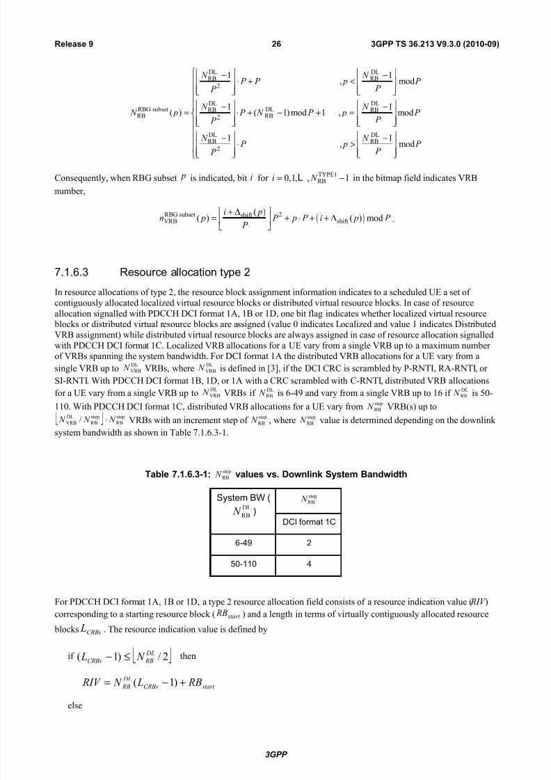
7.1.6.3 Resource allocation type 2
In resource allocations of type 2, the resource block assignment information indicates to a scheduled UE a set of
contiguously allocated localized virtual resource blocks or distributed virtual resource blocks. In case of resource
allocation signalled with PDCCH DCI format 1A, 1B or 1D, one bit flag indicates whether localized virtual resource blocks or distributed virtual resource blocks are assigned (value 0 indicates Localized and value 1 indicates Distributed
VRB assignment) while distributed virtual resource blocks are always assigned in case of resource allocation signalled
with PDCCH DCI format 1C. Localized VRB allocations for a UE vary from a single VRB up to a maximum number of VRBs spanning the system bandwidth. For DCI format 1A the distributed VRB allocations for a UE vary from a
single VRB up to DL
VRB N VRBs, whereDL
VRB N is defined in [3], if the DCI CRC is scrambled by P-RNTI, RA-RNTI, or
SI-RNTI. With PDCCH DCI format 1B, 1D, or 1A with a CRC scrambled with C-RNTI, distributed VRB allocations
for a UE vary from a single VRB up to DL
VRB N VRBs if DL
RB N is 6-49 and vary from a single VRB up to 16 if DL
RB N is 50-
110. With PDCCH DCI format 1C, distributed VRB allocations for a UE vary from
step
RB N VRB(s) up to step
RB
step
RB
DL
VRB / N N N ⋅ VRBs with an increment step of step
RB N , wherestep
RB N value is determined depending on the downlink
system bandwidth as shown in Table 7.1.6.3-1.
Table 7.1.6.3-1:step
RB N values vs. Downlink System Bandwidth
System BW (DL
RB N )
step
RB N
DCI format 1C
6-49 2
50-110 4
For PDCCH DCI format 1A, 1B or 1D, a type 2 resource allocation field consists of a resource indication value ( RIV )
corresponding to a starting resource block ( start RB ) and a length in terms of virtually contiguously allocated resource
blocks CRBs L . The resource indication value is defined by
if 2/)1( DL
RBCRBs N L ≤− then
start CRBs
DL
RB RB L N RIV +−= )1(
else
3GPP
3GPP TS 36.213 V9.3.0 (2010-09)26Release 9

7/29/2019 LTE Procedures 36213-930
http://slidepdf.com/reader/full/lte-procedures-36213-930 27/80
)1()1( start
DL
RBCRBs
DL
RB
DL
RB RB N L N N RIV −−++−=
where CRBs L ≥ 1 and shall not exceed start
DL
VRB RB N − .
For PDCCH DCI format 1C, a type 2 resource block assignment field consists of a resource indication value ( RIV )
corresponding to a starting resource block ( start RB =0 ,step
RB N ,step
RB2 N ,…, step
RB
step
RB
DL
VRB )1/( N N N − ) and a length in termsof virtually contiguously allocated resource blocks ( CRBs L = step
RB N ,step
RB2 N ,…, step
RB
step
RB
DL
VRB / N N N ⋅ ). The resource
indication value is defined by
if 2/)1( DL
VRBCRBs N L ′≤−′ then
start CRBs
DL
VRB B R L N RIV ′+−′′= )1(
else
)1()1( start
DL
VRBCRBs
DL
VRB
DL
VRB B R N L N N RIV ′−−′++′−′′=
where step
RBCRBsCRBs N L L /=′ , step
RB start start N RB B R /=′ and step
RB
DL
VRB
DL
VRB N N N /=′ . Here,
CRBs L′ ≥ 1 and shall not exceed start
DL
VRB B R N ′−′ .
7.1.7 Modulation order and transport block size determination
To determine the modulation order and transport block size(s) in the physical downlink shared channel, the UE shallfirst
− read the 5-bit “modulation and coding scheme” field ( MCS I ) in the DCI
and second if the DCI CRC is scrambled by P-RNTI, RA-RNTI, or SI-RNTI then
− for DCI format 1A:
o set the Table 7.1.7.2.1-1 column indicator PRB N to 1A
PRB N from Section 5.3.3.1.3 in [4]
− for DCI format 1C:
o use Table 7.1.7.2.3-1 for determining its transport block size.
else
− set PRB N ′ to the total number of allocated PRBs based on the procedure defined in Section 7.1.6.
if the transport block is transmitted in DwPTS of the special subframe in frame structure type 2, then
set the Table 7.1.7.2.1-1 column indicator { }PRBmax 0.75 , 1
PRB N N ′ = × ,
else, set the Table 7.1.7.2.1-1 column indicator PRB PRB N N ′= .
The UE may skip decoding a transport block in an initial transmission if the effective channel code rate is higher than
0.930, where the effective channel code rate is defined as the number of downlink information bits (including CRC bits)divided by the number of physical channel bits on PDSCH. If the UE skips decoding, the physical layer indicates to
higher layer that the transport block is not successfully decoded. For the special subframe configurations 0 and 5 with
normal downlink CP or configurations 0 and 4 with extended downlink CP, shown in table 4.2-1 [3], there shall be noPDSCH transmission in DwPTS of the special subframe.
3GPP
3GPP TS 36.213 V9.3.0 (2010-09)27Release 9

7/29/2019 LTE Procedures 36213-930
http://slidepdf.com/reader/full/lte-procedures-36213-930 28/80
7.1.7.1 Modulation order determination
The UE shall use mQ = 2 if the DCI CRC is scrambled by P-RNTI, RA-RNTI, or SI-RNTI, otherwise, the UE shall use
MCS I and Table 7.1.7.1-1 to determine the modulation order ( mQ ) used in the physical downlink shared channel.
Table 7.1.7.1-1: Modulation and TBS index table for PDSCH
MCS Index
MCS I
Modulation Order
mQ
TBS Index
TBS I
0 2 0
1 2 1
2 2 2
3 2 3
4 2 4
5 2 5
6 2 6
7 2 7
8 2 8
9 2 9
10 4 9
11 4 10
12 4 11
13 4 12
14 4 13
15 4 14
16 4 15
17 6 15
18 6 16
19 6 17
20 6 18
21 6 1922 6 20
23 6 21
24 6 22
25 6 23
26 6 24
27 6 25
28 6 26
29 2
reserved30 4
31 6
7.1.7.2 Transport block size determination
If the DCI CRC is scrambled by P-RNTI, RA-RNTI, or SI-RNTI then
− for DCI format 1A:
o the UE shall set the TBS index (TBS I ) equal to
MCS I and determine its TBS by the procedure in
Section 7.1.7.2.1.
− for DCI format 1C:
o the UE shall set the TBS index (TBS I ) equal to
MCS I and determine its TBS from Table 7.1.7.2.3-1.
else
3GPP
3GPP TS 36.213 V9.3.0 (2010-09)28Release 9

7/29/2019 LTE Procedures 36213-930
http://slidepdf.com/reader/full/lte-procedures-36213-930 29/80
for 280 MCS ≤≤ I , the UE shall first determine the TBS index ( TBS I ) using MCS I and Table 7.1.7.1-1 except if
the transport block is disabled in DCI formats 2, 2A and 2B as specified below. For a transport block that is notmapped to two-layer spatial multiplexing, the TBS is determined by the procedure in Section 7.1.7.2.1. For a
transport block that is mapped to two-layer spatial multiplexing, the TBS is determined by the procedure inSection 7.1.7.2.2.
for 3129 MCS ≤≤ I , the TBS is assumed to be as determined from DCI transported in the latest PDCCH for the
same transport block using 280 MCS ≤≤ I . If there is no PDCCH for the same transport block using
280 MCS ≤≤ I , and if the initial PDSCH for the same transport block is semi-persistently scheduled, the TBS
shall be determined from the most recent semi-persistent scheduling assignment PDCCH.
In DCI formats 2, 2A and 2B a transport block is disabled if 0MCS = I and if rvidx = 1 otherwise the transport
block is enabled.
The NDI and HARQ process ID, as signalled on PDCCH, and the TBS, as determined above, shall be delivered to
higher layers.
7.1.7.2.1 Transport blocks not mapped to two-layer spatial multiplexing
For 1101 PRB ≤≤ N , the TBS is given by the ( TBS I , PRB N ) entry of Table 7.1.7.2.1-1.
Table 7.1.7.2.1-1: Transport block size table (dimension 27×110)
TBS I PRB N
1 2 3 4 5 6 7 8 9 10
0 16 32 56 88 120 152 176 208 224 256
1 24 56 88 144 176 208 224 256 328 344
2 32 72 144 176 208 256 296 328 376 424
3 40 104 176 208 256 328 392 440 504 568
4 56 120 208 256 328 408 488 552 632 6965 72 144 224 328 424 504 600 680 776 872
6 328 176 256 392 504 600 712 808 936 1032
7 104 224 328 472 584 712 840 968 1096 1224
8 120 256 392 536 680 808 968 1096 1256 1384
9 136 296 456 616 776 936 1096 1256 1416 1544
10 144 328 504 680 872 1032 1224 1384 1544 1736
11 176 376 584 776 1000 1192 1384 1608 1800 2024
12 208 440 680 904 1128 1352 1608 1800 2024 2280
13 224 488 744 1000 1256 1544 1800 2024 2280 2536
14 256 552 840 1128 1416 1736 1992 2280 2600 2856
15 280 600 904 1224 1544 1800 2152 2472 2728 3112
16 328 632 968 1288 1608 1928 2280 2600 2984 324017 336 696 1064 1416 1800 2152 2536 2856 3240 3624
18 376 776 1160 1544 1992 2344 2792 3112 3624 4008
19 408 840 1288 1736 2152 2600 2984 3496 3880 4264
20 440 904 1384 1864 2344 2792 3240 3752 4136 4584
21 488 1000 1480 1992 2472 2984 3496 4008 4584 4968
22 520 1064 1608 2152 2664 3240 3752 4264 4776 5352
23 552 1128 1736 2280 2856 3496 4008 4584 5160 5736
24 584 1192 1800 2408 2984 3624 4264 4968 5544 5992
25 616 1256 1864 2536 3112 3752 4392 5160 5736 6200
26 712 1480 2216 2984 3752 4392 5160 5992 6712 7480
TBS I PRB N
11 12 13 14 15 16 17 18 19 20
0 288 328 344 376 392 424 456 488 504 536
1 376 424 456 488 520 568 600 632 680 712
3GPP
3GPP TS 36.213 V9.3.0 (2010-09)29Release 9

7/29/2019 LTE Procedures 36213-930
http://slidepdf.com/reader/full/lte-procedures-36213-930 30/80
2 472 520 568 616 648 696 744 776 840 872
3 616 680 744 808 872 904 968 1032 1096 1160
4 776 840 904 1000 1064 1128 1192 1288 1352 1416
5 968 1032 1128 1224 1320 1384 1480 1544 1672 1736
6 1128 1224 1352 1480 1544 1672 1736 1864 1992 2088
7 1320 1480 1608 1672 1800 1928 2088 2216 2344 2472
8 1544 1672 1800 1928 2088 2216 2344 2536 2664 27929 1736 1864 2024 2216 2344 2536 2664 2856 2984 3112
10 1928 2088 2280 2472 2664 2792 2984 3112 3368 3496
11 2216 2408 2600 2792 2984 3240 3496 3624 3880 4008
12 2472 2728 2984 3240 3368 3624 3880 4136 4392 4584
13 2856 3112 3368 3624 3880 4136 4392 4584 4968 5160
14 3112 3496 3752 4008 4264 4584 4968 5160 5544 5736
15 3368 3624 4008 4264 4584 4968 5160 5544 5736 6200
16 3624 3880 4264 4584 4968 5160 5544 5992 6200 6456
17 4008 4392 4776 5160 5352 5736 6200 6456 6712 7224
18 4392 4776 5160 5544 5992 6200 6712 7224 7480 7992
19 4776 5160 5544 5992 6456 6968 7224 7736 8248 8504
20 5160 5544 5992 6456 6968 7480 7992 8248 8760 914421 5544 5992 6456 6968 7480 7992 8504 9144 9528 9912
22 5992 6456 6968 7480 7992 8504 9144 9528 10296 10680
23 6200 6968 7480 7992 8504 9144 9912 10296 11064 11448
24 6712 7224 7992 8504 9144 9912 10296 11064 11448 12216
25 6968 7480 8248 8760 9528 10296 10680 11448 12216 12576
26 8248 8760 9528 10296 11064 11832 12576 13536 14112 14688
TBS I PRB N
21 22 23 24 25 26 27 28 29 30
0 568 600 616 648 680 712 744 776 776 808
1 744 776 808 872 904 936 968 1000 1032 1064
2 936 968 1000 1064 1096 1160 1192 1256 1288 1320
3 1224 1256 1320 1384 1416 1480 1544 1608 1672 1736
4 1480 1544 1608 1736 1800 1864 1928 1992 2088 2152
5 1864 1928 2024 2088 2216 2280 2344 2472 2536 2664
6 2216 2280 2408 2472 2600 2728 2792 2984 2984 3112
7 2536 2664 2792 2984 3112 3240 3368 3368 3496 3624
8 2984 3112 3240 3368 3496 3624 3752 3880 4008 4264
9 3368 3496 3624 3752 4008 4136 4264 4392 4584 4776
10 3752 3880 4008 4264 4392 4584 4776 4968 5160 5352
11 4264 4392 4584 4776 4968 5352 5544 5736 5992 5992
12 4776 4968 5352 5544 5736 5992 6200 6456 6712 6712
13 5352 5736 5992 6200 6456 6712 6968 7224 7480 7736
14 5992 6200 6456 6968 7224 7480 7736 7992 8248 8504
15 6456 6712 6968 7224 7736 7992 8248 8504 8760 914416 6712 7224 7480 7736 7992 8504 8760 9144 9528 9912
17 7480 7992 8248 8760 9144 9528 9912 10296 10296 10680
18 8248 8760 9144 9528 9912 10296 10680 11064 11448 11832
19 9144 9528 9912 10296 10680 11064 11448 12216 12576 12960
20 9912 10296 10680 11064 11448 12216 12576 12960 13536 14112
21 10680 11064 11448 12216 12576 12960 13536 14112 14688 15264
22 11448 11832 12576 12960 13536 14112 14688 15264 15840 16416
23 12216 12576 12960 13536 14112 14688 15264 15840 16416 16992
24 12960 13536 14112 14688 15264 15840 16416 16992 17568 18336
25 13536 14112 14688 15264 15840 16416 16992 17568 18336 19080
26 15264 16416 16992 17568 18336 19080 19848 20616 21384 22152
TBS I PRB N
31 32 33 34 35 36 37 38 39 40
0 840 872 904 936 968 1000 1032 1032 1064 1096
3GPP
3GPP TS 36.213 V9.3.0 (2010-09)30Release 9

7/29/2019 LTE Procedures 36213-930
http://slidepdf.com/reader/full/lte-procedures-36213-930 31/80
1 1128 1160 1192 1224 1256 1288 1352 1384 1416 1416
2 1384 1416 1480 1544 1544 1608 1672 1672 1736 1800
3 1800 1864 1928 1992 2024 2088 2152 2216 2280 2344
4 2216 2280 2344 2408 2472 2600 2664 2728 2792 2856
5 2728 2792 2856 2984 3112 3112 3240 3368 3496 3496
6 3240 3368 3496 3496 3624 3752 3880 4008 4136 4136
7 3752 3880 4008 4136 4264 4392 4584 4584 4776 49688 4392 4584 4584 4776 4968 4968 5160 5352 5544 5544
9 4968 5160 5160 5352 5544 5736 5736 5992 6200 6200
10 5544 5736 5736 5992 6200 6200 6456 6712 6712 6968
11 6200 6456 6712 6968 6968 7224 7480 7736 7736 7992
12 6968 7224 7480 7736 7992 8248 8504 8760 8760 9144
13 7992 8248 8504 8760 9144 9144 9528 9912 9912 10296
14 8760 9144 9528 9912 9912 10296 10680 11064 11064 11448
15 9528 9912 10296 10296 10680 11064 11448 11832 11832 12216
16 9912 10296 10680 11064 11448 11832 12216 12216 12576 12960
17 11064 11448 11832 12216 12576 12960 13536 13536 14112 14688
18 12216 12576 12960 13536 14112 14112 14688 15264 15264 15840
19 13536 13536 14112 14688 15264 15264 15840 16416 16992 1699220 14688 14688 15264 15840 16416 16992 16992 17568 18336 18336
21 15840 15840 16416 16992 17568 18336 18336 19080 19848 19848
22 16992 16992 17568 18336 19080 19080 19848 20616 21384 21384
23 17568 18336 19080 19848 19848 20616 21384 22152 22152 22920
24 19080 19848 19848 20616 21384 22152 22920 22920 23688 24496
25 19848 20616 20616 21384 22152 22920 23688 24496 24496 25456
26 22920 23688 24496 25456 25456 26416 27376 28336 29296 29296
TBS I PRB N
41 42 43 44 45 46 47 48 49 50
0 1128 1160 1192 1224 1256 1256 1288 1320 1352 1384
1 1480 1544 1544 1608 1608 1672 1736 1736 1800 1800
2 1800 1864 1928 1992 2024 2088 2088 2152 2216 2216
3 2408 2472 2536 2536 2600 2664 2728 2792 2856 2856
4 2984 2984 3112 3112 3240 3240 3368 3496 3496 3624
5 3624 3752 3752 3880 4008 4008 4136 4264 4392 4392
6 4264 4392 4584 4584 4776 4776 4968 4968 5160 5160
7 4968 5160 5352 5352 5544 5736 5736 5992 5992 6200
8 5736 5992 5992 6200 6200 6456 6456 6712 6968 6968
9 6456 6712 6712 6968 6968 7224 7480 7480 7736 7992
10 7224 7480 7480 7736 7992 7992 8248 8504 8504 8760
11 8248 8504 8760 8760 9144 9144 9528 9528 9912 9912
12 9528 9528 9912 9912 10296 10680 10680 11064 11064 11448
13 10680 10680 11064 11448 11448 11832 12216 12216 12576 12960
14 11832 12216 12216 12576 12960 12960 13536 13536 14112 1411215 12576 12960 12960 13536 13536 14112 14688 14688 15264 15264
16 13536 13536 14112 14112 14688 14688 15264 15840 15840 16416
17 14688 15264 15264 15840 16416 16416 16992 17568 17568 18336
18 16416 16416 16992 17568 17568 18336 18336 19080 19080 19848
19 17568 18336 18336 19080 19080 19848 20616 20616 21384 21384
20 19080 19848 19848 20616 20616 21384 22152 22152 22920 22920
21 20616 21384 21384 22152 22920 22920 23688 24496 24496 25456
22 22152 22920 22920 23688 24496 24496 25456 25456 26416 27376
23 23688 24496 24496 25456 25456 26416 27376 27376 28336 28336
24 25456 25456 26416 26416 27376 28336 28336 29296 29296 30576
25 26416 26416 27376 28336 28336 29296 29296 30576 31704 31704
26 30576 30576 31704 32856 32856 34008 35160 35160 36696 36696
TBS I PRB N
51 52 53 54 55 56 57 58 59 60
3GPP
3GPP TS 36.213 V9.3.0 (2010-09)31Release 9

7/29/2019 LTE Procedures 36213-930
http://slidepdf.com/reader/full/lte-procedures-36213-930 32/80
0 1416 1416 1480 1480 1544 1544 1608 1608 1608 1672
1 1864 1864 1928 1992 1992 2024 2088 2088 2152 2152
2 2280 2344 2344 2408 2472 2536 2536 2600 2664 2664
3 2984 2984 3112 3112 3240 3240 3368 3368 3496 3496
4 3624 3752 3752 3880 4008 4008 4136 4136 4264 4264
5 4584 4584 4776 4776 4776 4968 4968 5160 5160 5352
6 5352 5352 5544 5736 5736 5992 5992 5992 6200 62007 6200 6456 6456 6712 6712 6712 6968 6968 7224 7224
8 7224 7224 7480 7480 7736 7736 7992 7992 8248 8504
9 7992 8248 8248 8504 8760 8760 9144 9144 9144 9528
10 9144 9144 9144 9528 9528 9912 9912 10296 10296 10680
11 10296 10680 10680 11064 11064 11448 11448 11832 11832 12216
12 11832 11832 12216 12216 12576 12576 12960 12960 13536 13536
13 12960 13536 13536 14112 14112 14688 14688 14688 15264 15264
14 14688 14688 15264 15264 15840 15840 16416 16416 16992 16992
15 15840 15840 16416 16416 16992 16992 17568 17568 18336 18336
16 16416 16992 16992 17568 17568 18336 18336 19080 19080 19848
17 18336 19080 19080 19848 19848 20616 20616 20616 21384 21384
18 19848 20616 21384 21384 22152 22152 22920 22920 23688 2368819 22152 22152 22920 22920 23688 24496 24496 25456 25456 25456
20 23688 24496 24496 25456 25456 26416 26416 27376 27376 28336
21 25456 26416 26416 27376 27376 28336 28336 29296 29296 30576
22 27376 28336 28336 29296 29296 30576 30576 31704 31704 32856
23 29296 29296 30576 30576 31704 31704 32856 32856 34008 34008
24 31704 31704 32856 32856 34008 34008 35160 35160 36696 36696
25 32856 32856 34008 34008 35160 35160 36696 36696 37888 37888
26 37888 37888 39232 40576 40576 40576 42368 42368 43816 43816
TBS I PRB N
61 62 63 64 65 66 67 68 69 70
0 1672 1736 1736 1800 1800 1800 1864 1864 1928 1928
1 2216 2280 2280 2344 2344 2408 2472 2472 2536 2536
2 2728 2792 2856 2856 2856 2984 2984 3112 3112 3112
3 3624 3624 3624 3752 3752 3880 3880 4008 4008 4136
4 4392 4392 4584 4584 4584 4776 4776 4968 4968 4968
5 5352 5544 5544 5736 5736 5736 5992 5992 5992 6200
6 6456 6456 6456 6712 6712 6968 6968 6968 7224 7224
7 7480 7480 7736 7736 7992 7992 8248 8248 8504 8504
8 8504 8760 8760 9144 9144 9144 9528 9528 9528 9912
9 9528 9912 9912 10296 10296 10296 10680 10680 11064 11064
10 10680 11064 11064 11448 11448 11448 11832 11832 12216 12216
11 12216 12576 12576 12960 12960 13536 13536 13536 14112 14112
12 14112 14112 14112 14688 14688 15264 15264 15264 15840 15840
13 15840 15840 16416 16416 16992 16992 16992 17568 17568 1833614 17568 17568 18336 18336 18336 19080 19080 19848 19848 19848
15 18336 19080 19080 19848 19848 20616 20616 20616 21384 21384
16 19848 19848 20616 20616 21384 21384 22152 22152 22152 22920
17 22152 22152 22920 22920 23688 23688 24496 24496 24496 25456
18 24496 24496 24496 25456 25456 26416 26416 27376 27376 27376
19 26416 26416 27376 27376 28336 28336 29296 29296 29296 30576
20 28336 29296 29296 29296 30576 30576 31704 31704 31704 32856
21 30576 31704 31704 31704 32856 32856 34008 34008 35160 35160
22 32856 34008 34008 34008 35160 35160 36696 36696 36696 37888
23 35160 35160 36696 36696 37888 37888 37888 39232 39232 40576
24 36696 37888 37888 39232 39232 40576 40576 42368 42368 42368
25 39232 39232 40576 40576 40576 42368 42368 43816 43816 4381626 45352 45352 46888 46888 48936 48936 48936 51024 51024 52752
TBS I PRB N
3GPP
3GPP TS 36.213 V9.3.0 (2010-09)32Release 9

7/29/2019 LTE Procedures 36213-930
http://slidepdf.com/reader/full/lte-procedures-36213-930 33/80
71 72 73 74 75 76 77 78 79 80
0 1992 1992 2024 2088 2088 2088 2152 2152 2216 2216
1 2600 2600 2664 2728 2728 2792 2792 2856 2856 2856
2 3240 3240 3240 3368 3368 3368 3496 3496 3496 3624
3 4136 4264 4264 4392 4392 4392 4584 4584 4584 4776
4 5160 5160 5160 5352 5352 5544 5544 5544 5736 5736
5 6200 6200 6456 6456 6712 6712 6712 6968 6968 69686 7480 7480 7736 7736 7736 7992 7992 8248 8248 8248
7 8760 8760 8760 9144 9144 9144 9528 9528 9528 9912
8 9912 9912 10296 10296 10680 10680 10680 11064 11064 11064
9 11064 11448 11448 11832 11832 11832 12216 12216 12576 12576
10 12576 12576 12960 12960 12960 13536 13536 13536 14112 14112
11 14112 14688 14688 14688 15264 15264 15840 15840 15840 16416
12 16416 16416 16416 16992 16992 17568 17568 17568 18336 18336
13 18336 18336 19080 19080 19080 19848 19848 19848 20616 20616
14 20616 20616 20616 21384 21384 22152 22152 22152 22920 22920
15 22152 22152 22152 22920 22920 23688 23688 23688 24496 24496
16 22920 23688 23688 24496 24496 24496 25456 25456 25456 26416
17 25456 26416 26416 26416 27376 27376 27376 28336 28336 2929618 28336 28336 29296 29296 29296 30576 30576 30576 31704 31704
19 30576 30576 31704 31704 32856 32856 32856 34008 34008 34008
20 32856 34008 34008 34008 35160 35160 35160 36696 36696 36696
21 35160 36696 36696 36696 37888 37888 39232 39232 39232 40576
22 37888 39232 39232 40576 40576 40576 42368 42368 42368 43816
23 40576 40576 42368 42368 43816 43816 43816 45352 45352 45352
24 43816 43816 45352 45352 45352 46888 46888 46888 48936 48936
25 45352 45352 46888 46888 46888 48936 48936 48936 51024 51024
26 52752 52752 55056 55056 55056 55056 57336 57336 57336 59256
TBS I PRB N
81 82 83 84 85 86 87 88 89 90
0 2280 2280 2280 2344 2344 2408 2408 2472 2472 2536
1 2984 2984 2984 3112 3112 3112 3240 3240 3240 3240
2 3624 3624 3752 3752 3880 3880 3880 4008 4008 4008
3 4776 4776 4776 4968 4968 4968 5160 5160 5160 5352
4 5736 5992 5992 5992 5992 6200 6200 6200 6456 6456
5 7224 7224 7224 7480 7480 7480 7736 7736 7736 7992
6 8504 8504 8760 8760 8760 9144 9144 9144 9144 9528
7 9912 9912 10296 10296 10296 10680 10680 10680 11064 11064
8 11448 11448 11448 11832 11832 12216 12216 12216 12576 12576
9 12960 12960 12960 13536 13536 13536 13536 14112 14112 14112
10 14112 14688 14688 14688 14688 15264 15264 15264 15840 15840
11 16416 16416 16992 16992 16992 17568 17568 17568 18336 18336
12 18336 19080 19080 19080 19080 19848 19848 19848 20616 2061613 20616 21384 21384 21384 22152 22152 22152 22920 22920 22920
14 22920 23688 23688 24496 24496 24496 25456 25456 25456 25456
15 24496 25456 25456 25456 26416 26416 26416 27376 27376 27376
16 26416 26416 27376 27376 27376 28336 28336 28336 29296 29296
17 29296 29296 30576 30576 30576 30576 31704 31704 31704 32856
18 31704 32856 32856 32856 34008 34008 34008 35160 35160 35160
19 35160 35160 35160 36696 36696 36696 37888 37888 37888 39232
20 37888 37888 39232 39232 39232 40576 40576 40576 42368 42368
21 40576 40576 42368 42368 42368 43816 43816 43816 45352 45352
22 43816 43816 45352 45352 45352 46888 46888 46888 48936 48936
23 46888 46888 46888 48936 48936 48936 51024 51024 51024 51024
24 48936 51024 51024 51024 52752 52752 52752 52752 55056 5505625 51024 52752 52752 52752 55056 55056 55056 55056 57336 57336
26 59256 59256 61664 61664 61664 63776 63776 63776 66592 66592
3GPP
3GPP TS 36.213 V9.3.0 (2010-09)33Release 9

7/29/2019 LTE Procedures 36213-930
http://slidepdf.com/reader/full/lte-procedures-36213-930 34/80
TBS I PRB N
91 92 93 94 95 96 97 98 99 100
0 2536 2536 2600 2600 2664 2664 2728 2728 2728 2792
1 3368 3368 3368 3496 3496 3496 3496 3624 3624 3624
2 4136 4136 4136 4264 4264 4264 4392 4392 4392 4584
3 5352 5352 5352 5544 5544 5544 5736 5736 5736 57364 6456 6456 6712 6712 6712 6968 6968 6968 6968 7224
5 7992 7992 8248 8248 8248 8504 8504 8760 8760 8760
6 9528 9528 9528 9912 9912 9912 10296 10296 10296 10296
7 11064 11448 11448 11448 11448 11832 11832 11832 12216 12216
8 12576 12960 12960 12960 13536 13536 13536 13536 14112 14112
9 14112 14688 14688 14688 15264 15264 15264 15264 15840 15840
10 15840 16416 16416 16416 16992 16992 16992 16992 17568 17568
11 18336 18336 19080 19080 19080 19080 19848 19848 19848 19848
12 20616 21384 21384 21384 21384 22152 22152 22152 22920 22920
13 23688 23688 23688 24496 24496 24496 25456 25456 25456 25456
14 26416 26416 26416 27376 27376 27376 28336 28336 28336 28336
15 28336 28336 28336 29296 29296 29296 29296 30576 30576 3057616 29296 30576 30576 30576 30576 31704 31704 31704 31704 32856
17 32856 32856 34008 34008 34008 35160 35160 35160 35160 36696
18 36696 36696 36696 37888 37888 37888 37888 39232 39232 39232
19 39232 39232 40576 40576 40576 40576 42368 42368 42368 43816
20 42368 42368 43816 43816 43816 45352 45352 45352 46888 46888
21 45352 46888 46888 46888 46888 48936 48936 48936 48936 51024
22 48936 48936 51024 51024 51024 51024 52752 52752 52752 55056
23 52752 52752 52752 55056 55056 55056 55056 57336 57336 57336
24 55056 57336 57336 57336 57336 59256 59256 59256 61664 61664
25 57336 59256 59256 59256 61664 61664 61664 61664 63776 63776
26 66592 68808 68808 68808 71112 71112 71112 73712 73712 75376
TBS I PRB N
101 102 103 104 105 106 107 108 109 110
0 2792 2856 2856 2856 2984 2984 2984 2984 2984 3112
1 3752 3752 3752 3752 3880 3880 3880 4008 4008 4008
2 4584 4584 4584 4584 4776 4776 4776 4776 4968 4968
3 5992 5992 5992 5992 6200 6200 6200 6200 6456 6456
4 7224 7224 7480 7480 7480 7480 7736 7736 7736 7992
5 8760 9144 9144 9144 9144 9528 9528 9528 9528 9528
6 10680 10680 10680 10680 11064 11064 11064 11448 11448 11448
7 12216 12576 12576 12576 12960 12960 12960 12960 13536 13536
8 14112 14112 14688 14688 14688 14688 15264 15264 15264 15264
9 15840 16416 16416 16416 16416 16992 16992 16992 16992 17568
10 17568 18336 18336 18336 18336 18336 19080 19080 19080 1908011 20616 20616 20616 21384 21384 21384 21384 22152 22152 22152
12 22920 23688 23688 23688 23688 24496 24496 24496 24496 25456
13 26416 26416 26416 26416 27376 27376 27376 27376 28336 28336
14 29296 29296 29296 29296 30576 30576 30576 30576 31704 31704
15 30576 31704 31704 31704 31704 32856 32856 32856 34008 34008
16 32856 32856 34008 34008 34008 34008 35160 35160 35160 35160
17 36696 36696 36696 37888 37888 37888 39232 39232 39232 39232
18 40576 40576 40576 40576 42368 42368 42368 42368 43816 43816
19 43816 43816 43816 45352 45352 45352 46888 46888 46888 46888
20 46888 46888 48936 48936 48936 48936 48936 51024 51024 51024
21 51024 51024 51024 52752 52752 52752 52752 55056 55056 55056
22 55056 55056 55056 57336 57336 57336 57336 59256 59256 5925623 57336 59256 59256 59256 59256 61664 61664 61664 61664 63776
24 61664 61664 63776 63776 63776 63776 66592 66592 66592 66592
25 63776 63776 66592 66592 66592 66592 68808 68808 68808 71112
3GPP
3GPP TS 36.213 V9.3.0 (2010-09)34Release 9

7/29/2019 LTE Procedures 36213-930
http://slidepdf.com/reader/full/lte-procedures-36213-930 35/80
26 75376 75376 75376 75376 75376 75376 75376 75376 75376 75376
7.1.7.2.2 Transport blocks mapped to two-layer spatial multiplexing
For 551 PRB ≤≤ N , the TBS is given by the ( TBS I , PRB2 N ⋅ ) entry of Table 7.1.7.2.1-1.
For 11056 PRB ≤≤ N , a baseline TBS_L1 is taken from the ( TBS I , PRB N ) entry of Table 7.1.7.2.1-1, which is then
translated into TBS_L2 using the mapping rule shown in Table 7.1.7.2.2-1. The TBS is given by TBS_L2.
Table 7.1.7.2.2-1: One-layer to two-layer TBS translation table
TBS_L1 TBS_L2 TBS_L1 TBS_L2 TBS_L1 TBS_L2 TBS_L1 TBS_L2
1544 3112 3752 7480 10296 20616 28336 57336
1608 3240 3880 7736 10680 21384 29296 59256
1672 3368 4008 7992 11064 22152 30576 61664
1736 3496 4136 8248 11448 22920 31704 63776
1800 3624 4264 8504 11832 23688 32856 665921864 3752 4392 8760 12216 24496 34008 68808
1928 3880 4584 9144 12576 25456 35160 71112
1992 4008 4776 9528 12960 25456 36696 73712
2024 4008 4968 9912 13536 27376 37888 76208
2088 4136 5160 10296 14112 28336 39232 78704
2152 4264 5352 10680 14688 29296 40576 81176
2216 4392 5544 11064 15264 30576 42368 84760
2280 4584 5736 11448 15840 31704 43816 87936
2344 4776 5992 11832 16416 32856 45352 90816
2408 4776 6200 12576 16992 34008 46888 93800
2472 4968 6456 12960 17568 35160 48936 97896
2536 5160 6712 13536 18336 36696 51024 1018402600 5160 6968 14112 19080 37888 52752 105528
2664 5352 7224 14688 19848 39232 55056 110136
2728 5544 7480 14688 20616 40576 57336 115040
2792 5544 7736 15264 21384 42368 59256 119816
2856 5736 7992 15840 22152 43816 61664 124464
2984 5992 8248 16416 22920 45352 63776 128496
3112 6200 8504 16992 23688 46888 66592 133208
3240 6456 8760 17568 24496 48936 68808 137792
3368 6712 9144 18336 25456 51024 71112 142248
3496 6968 9528 19080 26416 52752 73712 146856
3624 7224 9912 19848 27376 55056 75376 149776
7.1.7.2.3 Transport blocks mapped for DCI Format 1C
The TBS is given by the TBS I entry of Table 7.1.7.2.3-1.
Table 7.1.7.2.3-1: Transport Block Size Table for DCI format 1C
TBS I 0 1 2 3 4 5 6 7 8 9 10 11 12 13 14 15
TBS 40 56 72 120 136 144 176 208 224 256 280 296 328 336 392 488
TBS I 16 17 18 19 20 21 22 23 24 25 26 27 28 29 30 31
TBS 552 600 632 696 776 840 904 1000 1064 1128 1224 1288 1384 1480 1608 1736
3GPP
3GPP TS 36.213 V9.3.0 (2010-09)35Release 9
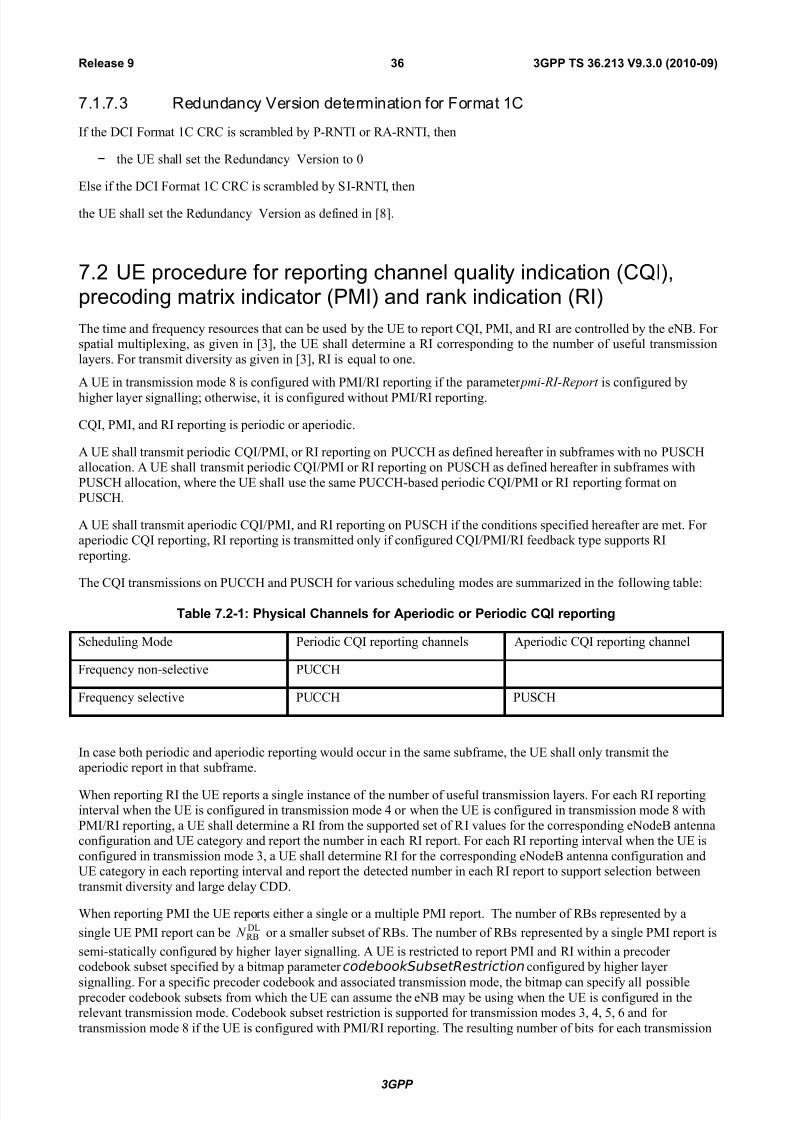
7/29/2019 LTE Procedures 36213-930
http://slidepdf.com/reader/full/lte-procedures-36213-930 36/80
7.1.7.3 Redundancy Version determination for Format 1C
If the DCI Format 1C CRC is scrambled by P-RNTI or RA-RNTI, then
− the UE shall set the Redundancy Version to 0
Else if the DCI Format 1C CRC is scrambled by SI-RNTI, then
the UE shall set the Redundancy Version as defined in [8].
7.2 UE procedure for reporting channel quality indication (CQI),precoding matrix indicator (PMI) and rank indication (RI)
The time and frequency resources that can be used by the UE to report CQI, PMI, and RI are controlled by the eNB. For spatial multiplexing, as given in [3], the UE shall determine a RI corresponding to the number of useful transmission
layers. For transmit diversity as given in [3], RI is equal to one.
A UE in transmission mode 8 is configured with PMI/RI reporting if the parameter pmi-RI-Report is configured by
higher layer signalling; otherwise, it is configured without PMI/RI reporting.
CQI, PMI, and RI reporting is periodic or aperiodic.
A UE shall transmit periodic CQI/PMI, or RI reporting on PUCCH as defined hereafter in subframes with no PUSCHallocation. A UE shall transmit periodic CQI/PMI or RI reporting on PUSCH as defined hereafter in subframes with
PUSCH allocation, where the UE shall use the same PUCCH-based periodic CQI/PMI or RI reporting format onPUSCH.
A UE shall transmit aperiodic CQI/PMI, and RI reporting on PUSCH if the conditions specified hereafter are met. For aperiodic CQI reporting, RI reporting is transmitted only if configured CQI/PMI/RI feedback type supports RI
reporting.
The CQI transmissions on PUCCH and PUSCH for various scheduling modes are summarized in the following table:
Table 7.2-1: Physical Channels for Aperiodic or Periodic CQI reporting
Scheduling Mode Periodic CQI reporting channels Aperiodic CQI reporting channel
Frequency non-selective PUCCH
Frequency selective PUCCH PUSCH
In case both periodic and aperiodic reporting would occur in the same subframe, the UE shall only transmit theaperiodic report in that subframe.
When reporting RI the UE reports a single instance of the number of useful transmission layers. For each RI reportinginterval when the UE is configured in transmission mode 4 or when the UE is configured in transmission mode 8 with
PMI/RI reporting, a UE shall determine a RI from the supported set of RI values for the corresponding eNodeB antennaconfiguration and UE category and report the number in each RI report. For each RI reporting interval when the UE is
configured in transmission mode 3, a UE shall determine RI for the corresponding eNodeB antenna configuration andUE category in each reporting interval and report the detected number in each RI report to support selection between
transmit diversity and large delay CDD.
When reporting PMI the UE reports either a single or a multiple PMI report. The number of RBs represented by a
single UE PMI report can beDLRB N or a smaller subset of RBs. The number of RBs represented by a single PMI report is
semi-statically configured by higher layer signalling. A UE is restricted to report PMI and RI within a precoder codebook subset specified by a bitmap parameter codebookSubsetRestriction configured by higher layer
signalling. For a specific precoder codebook and associated transmission mode, the bitmap can specify all possible precoder codebook subsets from which the UE can assume the eNB may be using when the UE is configured in therelevant transmission mode. Codebook subset restriction is supported for transmission modes 3, 4, 5, 6 and for
transmission mode 8 if the UE is configured with PMI/RI reporting. The resulting number of bits for each transmission
3GPP
3GPP TS 36.213 V9.3.0 (2010-09)36Release 9
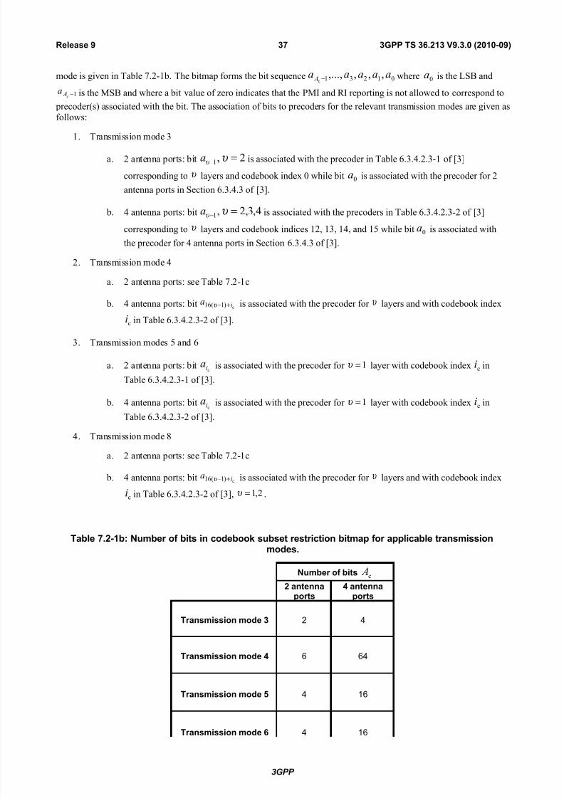
7/29/2019 LTE Procedures 36213-930
http://slidepdf.com/reader/full/lte-procedures-36213-930 37/80
mode is given in Table 7.2-1b. The bitmap forms the bit sequence 01231 ,,,,...,c
aaaaa A − where 0a is the LSB and
1−c Aa is the MSB and where a bit value of zero indicates that the PMI and RI reporting is not allowed to correspond to
precoder(s) associated with the bit. The association of bits to precoders for the relevant transmission modes are given asfollows:
1. Transmission mode 3
a. 2 antenna ports: bit 2,1 =− υ υ a is associated with the precoder in Table 6.3.4.2.3-1 of [3]
corresponding to υ layers and codebook index 0 while bit 0a is associated with the precoder for 2
antenna ports in Section 6.3.4.3 of [3].
b. 4 antenna ports: bit 4,3,2,1 =− υ υ a is associated with the precoders in Table 6.3.4.2.3-2 of [3]
corresponding to υ layers and codebook indices 12, 13, 14, and 15 while bit 0a is associated with
the precoder for 4 antenna ports in Section 6.3.4.3 of [3].
2. Transmission mode 4
a. 2 antenna ports: see Table 7.2-1c
b. 4 antenna ports: bit c)1(16 ia +−υ is associated with the precoder for υ layers and with codebook index
ci in Table 6.3.4.2.3-2 of [3].
3. Transmission modes 5 and 6
a. 2 antenna ports: bitci
a is associated with the precoder for 1=υ layer with codebook index ci in
Table 6.3.4.2.3-1 of [3].
b. 4 antenna ports: bitci
a is associated with the precoder for 1=υ layer with codebook index ci in
Table 6.3.4.2.3-2 of [3].
4. Transmission mode 8
a. 2 antenna ports: see Table 7.2-1c
b. 4 antenna ports: bit c)1(16 ia +−υ is associated with the precoder for υ layers and with codebook index
ci in Table 6.3.4.2.3-2 of [3], 2,1=υ .
Table 7.2-1b: Number of bits in codebook subset restriction bitmap for applicable transmissionmodes.
Number of bits c A
2 antennaports
4 antennaports
Transmission mode 3 2 4
Transmission mode 4 6 64
Transmission mode 5 4 16
Transmission mode 6 4 16
3GPP
3GPP TS 36.213 V9.3.0 (2010-09)37Release 9
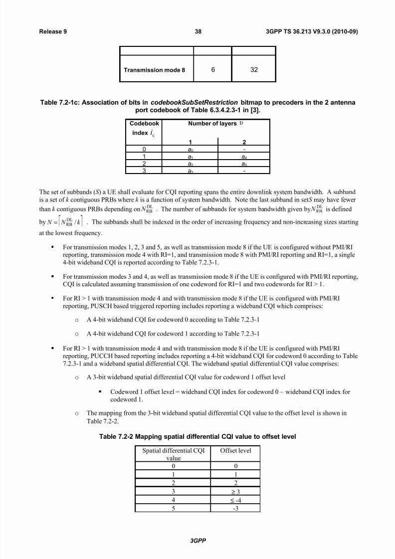
7/29/2019 LTE Procedures 36213-930
http://slidepdf.com/reader/full/lte-procedures-36213-930 38/80
Transmission mode 8 6 32
Table 7.2-1c: Association of bits in codebookSubSetRestriction bitmap to precoders in the 2 antennaport codebook of Table 6.3.4.2.3-1 in [3].
Codebook
index ci
Number of layers υ
1 20 a0 -
1 a1 a4
2 a2 a5
3 a3 -
The set of subbands (S ) a UE shall evaluate for CQI reporting spans the entire downlink system bandwidth. A subband
is a set of k contiguous PRBs where k is a function of system bandwidth. Note the last subband in set S may have fewer
than k contiguous PRBs depending onDLRB N . The number of subbands for system bandwidth given by
DLRB N is defined
by k N N /DLRB= . The subbands shall be indexed in the order of increasing frequency and non-increasing sizes starting
at the lowest frequency.
For transmission modes 1, 2, 3 and 5, as well as transmission mode 8 if the UE is configured without PMI/RIreporting, transmission mode 4 with RI=1, and transmission mode 8 with PMI/RI reporting and RI=1, a single
4-bit wideband CQI is reported according to Table 7.2.3-1.
For transmission modes 3 and 4, as well as transmission mode 8 if the UE is configured with PMI/RI reporting,CQI is calculated assuming transmission of one codeword for RI=1 and two codewords for RI > 1.
For RI > 1 with transmission mode 4 and with transmission mode 8 if the UE is configured with PMI/RI
reporting, PUSCH based triggered reporting includes reporting a wideband CQI which comprises:
o A 4-bit wideband CQI for codeword 0 according to Table 7.2.3-1
o A 4-bit wideband CQI for codeword 1 according to Table 7.2.3-1
For RI > 1 with transmission mode 4 and with transmission mode 8 if the UE is configured with PMI/RIreporting, PUCCH based reporting includes reporting a 4-bit wideband CQI for codeword 0 according to Table
7.2.3-1 and a wideband spatial differential CQI. The wideband spatial differential CQI value comprises:
o A 3-bit wideband spatial differential CQI value for codeword 1 offset level
Codeword 1 offset level = wideband CQI index for codeword 0 – wideband CQI index for codeword 1.
o The mapping from the 3-bit wideband spatial differential CQI value to the offset level is shown in
Table 7.2-2.
Table 7.2-2 Mapping spatial differential CQI value to offset level
Spatial differential CQI
value
Offset level
0 0
1 1
2 2
3 ≥ 34 ≤ -4
5 -3
3GPP
3GPP TS 36.213 V9.3.0 (2010-09)38Release 9

7/29/2019 LTE Procedures 36213-930
http://slidepdf.com/reader/full/lte-procedures-36213-930 39/80
6 -2
7 -1
7.2.1 Aperiodic CQI/PMI/RI Reporting using PUSCH
A UE shall perform aperiodic CQI, PMI and RI reporting using the PUSCH in subframe n+k , upon receiving in
subframe n either:
a DCI format 0, or
a Random Access Response Grant,
if the respective CQI request field is set to 1 and is not reserved.
When the CQI request field from a DCI format 0 is set to 1, for FDD k=4, and for TDD UL/DL configuration 1-6, k isgiven in Table 8-2. For TDD UL/DL configuration 0, if the MSB of the UL index is set to 1 and LSB of the UL index is
set to 0, k is given in Table 8-2; or if MSB of the UL index is set to 0 and LSB of the UL index is set to 1, k is equal to
7; or if both MSB and LSB of the UL index is set to 1, k is given in Table 8-2.
When the CQI request field from a Random Access Response Grant is set to 1 and is not reserved, k is equal to 1k if the
UL delay field in section 6.2 is set to zero, where 1k is given in section 6.1.1. The UE shall postpone aperiodic CQI,
PMI and RI reporting to the next available UL subframe if the UL delay field is set to 1.
The minimum reporting interval for aperiodic reporting of CQI and PMI and RI is 1 subframe. The subband size for
CQI shall be the same for transmitter-receiver configurations with and without precoding.
When aperiodic CQI/PMI/RI report with no transport block associated as defined in section 8.6.2 and positive SR is
transmitted in the same subframe, the UE shall transmit SR, and, if applicable, ACK/NAK, on PUCCH resources asdescribed in Section 10.1
A UE is semi-statically configured by higher layers to feed back CQI and PMI and corresponding RI on the same
PUSCH using one of the following reporting modes given in Table 7.2.1-1 and described below.
Table 7.2.1-1: CQI and PMI Feedback Types for PUSCH reporting Modes
PMI Feedback Type
No PMI Single PMI Multiple PMI
P U S C H C
Q I
F e e d b a c k T
y p e
Wideband Mode 1-2
(wideband CQI)
UE Selected Mode 2-0 Mode 2-2
(subband CQI)
Higher Layer-configured Mode 3-0 Mode 3-1
(subband CQI)
For each of the transmission modes defined in Section 7.1, the following reporting modes are supported on PUSCH:
Transmission mode 1 : Modes 2-0, 3-0Transmission mode 2 : Modes 2-0, 3-0
Transmission mode 3 : Modes 2-0, 3-0
Transmission mode 4 : Modes 1-2, 2-2, 3-1Transmission mode 5 : Mode 3-1Transmission mode 6 : Modes 1-2, 2-2, 3-1
Transmission mode 7 : Modes 2-0, 3-0
3GPP
3GPP TS 36.213 V9.3.0 (2010-09)39Release 9

7/29/2019 LTE Procedures 36213-930
http://slidepdf.com/reader/full/lte-procedures-36213-930 40/80
Transmission mode 8 : Modes 1-2, 2-2, 3-1 if the UE is configured with PMI/RI reporting; modes 2-0, 3-0 if theUE is configured without PMI/RI reporting
The aperiodic CQI reporting mode is given by the parameter cqi-ReportModeAperiodic which is configured by higher-
layer signalling.
For 7DL
RB ≤ N , PUSCH reporting modes are not supported.RI is only reported for transmission mode 3, transmission mode 4, and transmission mode 8 if the UE is configured with
PMI/RI reporting.
A RI report on an aperiodic reporting mode is valid only for CQI/PMI report on that aperiodic reporting mode
• Wideband feedback
o Mode 1-2 description:
For each subband a preferred precoding matrix is selected from the codebook subsetassuming transmission only in the subband
A UE shall report one wideband CQI value per codeword which is calculated assuming
the use of the corresponding selected precoding matrix in each subband andtransmission on set S subbands.
The UE shall report the selected precoding matrix indicator for each set S subband.
Subband size is given by Table 7.2.1-3.
For transmission mode 4 and transmission mode 8, the reported PMI and CQI values
are calculated conditioned on the reported RI. For other transmission modes they arereported conditioned on rank 1.
• Higher Layer-configured subband feedback
o Mode 3-0 description:
A UE shall report a wideband CQI value which is calculated assuming transmission on
set S subbands
The UE shall also report one subband CQI value for each set S subband. The subband
CQI value is calculated assuming transmission only in the subband
Both the wideband and subband CQI represent channel quality for the first codeword,even when RI>1.
For transmission mode 3 the reported CQI values are calculated conditioned on the
reported RI. For other transmission modes they are reported conditioned on rank 1.
o
Mode 3-1 description:
A single precoding matrix is selected from the codebook subset assuming transmissionon set S subbands
A UE shall report one subband CQI value per codeword for each set S subband which
are calculated assuming the use of the single precoding matrix in all subbands and assuming transmission in thecorresponding subband.
A UE shall report a wideband CQI value per codeword which is calculated assuming
the use of the single precoding matrix in all subbands and transmission on set S subbands
The UE shall report the single selected precoding matrix indicator
For transmission mode 4 and transmission mode 8, the reported PMI and CQI valuesare calculated conditioned on the reported RI. For other transmission modes they are reported conditioned on rank 1.
3GPP
3GPP TS 36.213 V9.3.0 (2010-09)40Release 9

7/29/2019 LTE Procedures 36213-930
http://slidepdf.com/reader/full/lte-procedures-36213-930 41/80
o Subband CQI value for each codeword are encoded differentially with respect to their respective
wideband CQI using 2-bits as defined by
Subband differential CQI offset level = subband CQI index – wideband CQI index. The
mapping from the 2-bit subband differential CQI value to the offset level is shown in Table 7.2.1-2.
Table 7.2.1-2: Mapping subband differential CQI value to offset level
Subband differential CQIvalue
Offset level
0 0
1 1
2 ≥ 2
3 ≤ -1
o Supported subband size (k ) is given in Table 7.2.1-3.
Table 7.2.1-3: Subband Size (k ) vs. System Bandwidth
System Bandwidth Subband SizeDLRB N (k )
6 - 7 NA
8 - 10 4
11 - 26 4
27 - 63 6
64 - 110 8
• UE-selected subband feedback
o Mode 2-0 description:
The UE shall select a set of M preferred subbands of size k (where k and M are given inTable 7.2.1-5 for each system bandwidth range) within the set of subbands S .
The UE shall also report one CQI value reflecting transmission only over the M selected
subbands determined in the previous step. The CQI represents channel quality for the first codeword, even when RI>1.
Additionally, the UE shall also report one wideband CQI value which is calculatedassuming transmission on set S subbands. The wideband CQI represents channel quality for the first codeword, even
when RI>1.
For transmission mode 3 the reported CQI values are calculated conditioned on thereported RI. For other transmission modes they are reported conditioned on rank 1.
o Mode 2-2 description:
The UE shall perform joint selection of the set of M preferred subbands of size k within the set of subbands S and a preferred single precoding matrix selected from the codebook subset that is preferred to be used for transmission over
the M selected subbands.
The UE shall report one CQI value per codeword reflecting transmission only over theselected M preferred subbands and using the same selected single precoding matrix in each of the M subbands.
The UE shall also report the selected single precoding matrix indicator preferred for the
M selected subbands.
A single precoding matrix is selected from the codebook subset assuming transmissionon set S subbands
3GPP
3GPP TS 36.213 V9.3.0 (2010-09)41Release 9

7/29/2019 LTE Procedures 36213-930
http://slidepdf.com/reader/full/lte-procedures-36213-930 42/80
A UE shall report a wideband CQI value per codeword which is calculated assumingthe use of the single precoding matrix in all subbands and transmission on set S subbands
A UE shall also report the selected single precoding matrix indicator for all set S subbands.
For transmission mode 4 and transmission mode 8, the reported PMI and CQI valuesare calculated conditioned on the reported RI. For other transmission modes they are reported conditioned on rank 1.
o For all UE-selected subband feedback modes the UE shall report the positions of the M selected
subbands using a combinatorial index r defined as
1
0
M i
i
N sr
M i
−
=
−=
−∑
where the set { } 1
0
M
i i s
−
= , ( 11 ,i i i s N s s +≤ ≤ < ) contains the M sorted subband indices and
<
≥
=
y x
y x y
x
y
x
0
is the extended binomial coefficient, resulting in unique label
−
∈ 1,,0 M
N r .
o The CQI value for the M selected subbands for each codeword is encoded differentially using 2-
bits relative to its respective wideband CQI as defined by
Differential CQI offset level = M selected subbands CQI index – wideband CQI index
The mapping from the 2-bit differential CQI value to the offset level is shown in Table
7.2.1-4.
Table 7.2.1-4: Mapping differential CQI value to offset level
Differential CQI value Offset level
0 ≤ 1
1 2
2 3
3 ≥ 4
o Supported subband size k and M values include those shown in Table 7.2.1-5. In Table 7.2.1-5 the k
and M values are a function of system bandwidth.
o The number of bits to denote the position of the M selected subbands is
= M N L 2log .
Table 7.2.1-5: Subband Size (k ) and Number of Subbands (M ) in S vs. Downlink System Bandwidth
System BandwidthSubband Size k (RBs) M DL
RB N
6 – 7 NA NA
8 – 10 2 1
11 – 26 2 3
27 – 63 3 564 – 110 4 6
3GPP
3GPP TS 36.213 V9.3.0 (2010-09)42Release 9

7/29/2019 LTE Procedures 36213-930
http://slidepdf.com/reader/full/lte-procedures-36213-930 43/80
7.2.2 Periodic CQI/PMI/RI Reporting using PUCCH
A UE is semi-statically configured by higher layers to periodically feed back different CQI, PMI, and RI on the PUCCHusing the reporting modes given in Table 7.2.2-1 and described below.
Table 7.2.2-1: CQI and PMI Feedback Types for PUCCH reporting Modes
PMI Feedback Type
No PMI Single PMI
P U C C H
C Q I
F e e d b a c k T y p e
Wideband Mode 1-0 Mode 1-1
(wideband CQI)
UE Selected Mode 2-0 Mode 2-1
(subband CQI)
For each of the transmission modes defined in Section 7.1, the following reporting modes are supported on PUCCH:
Transmission mode 1 : Modes 1-0, 2-0
Transmission mode 2 : Modes 1-0, 2-0Transmission mode 3 : Modes 1-0, 2-0
Transmission mode 4 : Modes 1-1, 2-1
Transmission mode 5 : Modes 1-1, 2-1Transmission mode 6 : Modes 1-1, 2-1
Transmission mode 7 : Modes 1-0, 2-0Transmission mode 8 : Modes 1-1, 2-1 if the UE is configured with PMI/RI reporting; modes 1-0, 2-0 if the UE is
configured without PMI/RI reporting
The periodic CQI reporting mode is given by the parameter cqi-FormatIndicatorPeriodic which is configured by
higher-layer signalling.
For the UE-selected subband CQI, a CQI report in a certain subframe describes the channel quality in a particular part
or in particular parts of the bandwidth described subsequently as bandwidth part (BP) or parts. The bandwidth partsshall be indexed in the order of increasing frequency and non-increasing sizes starting at the lowest frequency.
• There are a total of N subbands for a system bandwidth given byDLRB N where k N /
DLRB subbands are of size k.
If 0//DLRB
DLRB >− k N k N then one of the subbands is of size k N k N /
DLRB
DLRB ⋅− .
• A bandwidth part j is frequency-consecutive and consists of j N subbands where J bandwidth parts span S or
DLRB N as given in Table 7.2.2-2. If 1 J = then j N is J k N //DL
RB . If J>1 then j N is either J k N //DLRB or
1//DLRB − J k N , depending on
DLRB N , k and J .
• Each bandwidth part j, where 0 ≤ j ≤ J -1, is scanned in sequential order according to increasing frequency.
• For UE selected subband feedback a single subband out of j N subbands of a bandwidth part is selected along
with a corresponding L-bit label indexed in the order of increasing frequency, whereDL
2 RBlog / / L N k J = .
The CQI and PMI payload sizes of each PUCCH reporting mode are given in Table 7.2.2-3.
Four CQI/PMI and RI reporting types with distinct periods and offsets are supported for each PUCCH reporting mode
as given in Table 7.2.2-3:• Type 1 report supports CQI feedback for the UE selected sub-bands
• Type 2 report supports wideband CQI and PMI feedback.
3GPP
3GPP TS 36.213 V9.3.0 (2010-09)43Release 9

7/29/2019 LTE Procedures 36213-930
http://slidepdf.com/reader/full/lte-procedures-36213-930 44/80
• Type 3 report supports RI feedback
• Type 4 report supports wideband CQI
The periodicity p N (in subframes) and offset ,OFFSET CQI N (in subframes) for CQI/PMI reporting are determined based on
the parameter cqi-pmi-ConfigIndex ( /CQI PMI
I ) given in Table 7.2.2-1A for FDD and table 7.2.2-1C for TDD. The periodicity
RI M and relative offset ,OFFSET RI N for RI reporting are determined based on the parameter ri-ConfigIndex ( RI I ) given in
Table 7.2.2-1B. Both cqi-pmi-ConfigIndex and ri-ConfigIndex are configured by higher layer signalling. The relative
reporting offset for RI ,OFFSET RI N takes values from the set {0, 1,..., ( 1)} p N − − −
In the case where wideband CQI/PMI reporting is configured:
• The reporting instances for wideband CQI/PMI are subframes satisfying
( ),10 / 2 mod 0 f s OFFSET CQI P n n N N × + − = .
• In case RI reporting is configured, the reporting interval of the RI reporting is an integer multiple RI M of
period p N (in subframes).
o The reporting instances for RI are subframes satisfying ( ) 0mod2/10 ,, =⋅−−+× RI P RI OFFSET CQI OFFSET s f M N N N nn .
o In case of collision of RI and wideband CQI/PMI the wideband CQI/PMI is dropped.
In the case where both wideband CQI/PMI and subband CQI reporting are configured:
• The reporting instances for wideband CQI/PMI and subband CQI are subframes satisfying
0mod2/10 , =−+× P CQI OFFSET s f N N nn .
The wideband CQI/PMI report has period P H N ⋅ , and is reported on the subframes satisfying
( ) 0mod2/10 , =⋅−+× P CQI OFFSET s f N H N nn . The integer H is defined as 1 H J K = ⋅ + ,
where J is the number of bandwidth parts.
Between every two consecutive wideband CQI/PMI reports, the remaining J K ⋅ reporting instancesare used in sequence for subband CQI reports on K full cycles of bandwidth parts except when the
gap between two consecutive wideband CQI/PMI reports contains less than J K ⋅ reporting instances
due to a system frame number transition to 0, in which case the UE shall not transmit the remainder of
the subband CQI reports which have not been transmitted before the second of the two widebandCQI/PMI reports. Each full cycle of bandwidth parts shall be in increasing order starting from
bandwidth part 0 to bandwidth part 1 J − . The parameter K is configured by higher-layer signalling.
• In case RI reporting is configured, the reporting interval of RI is RI M times the wideband CQI/PMI period
P H N ⋅ , and RI is reported on the same PUCCH cyclic shift resource as both the wideband CQI/PMI and
subband CQI reports.
The reporting instances for RI are subframes satisfying
( ) 0mod2/10 ,, =⋅⋅−−+× RI P RI OFFSET CQI OFFSET s f M N H N N nn .In case of collision between
RI and wideband CQI/PMI or subband CQI, the wideband CQI/PMI or subband CQI is dropped.
See section 10.1 regarding UE behaviour for collision between CQI/PMI/RI and ACK/NACK and the corresponding PUCCH
format assignment.
The CQI/PMI or RI report shall be transmitted on the PUCCH resource)2(
PUCCHn as defined in [3], where)2(
PUCCHn is UE
specific and configured by higher layers.
In case of collision between CQI/PMI/RI and positive SR in a same subframe, CQI/PMI/RI is dropped.
3GPP
3GPP TS 36.213 V9.3.0 (2010-09)44Release 9

7/29/2019 LTE Procedures 36213-930
http://slidepdf.com/reader/full/lte-procedures-36213-930 45/80
Table 7.2.2-1A: Mapping of /CQI PMI I to p N and ,OFFSET CQI N for FDD.
/CQI PMI I Value of p N Value of ,OFFSET CQI N
0 ≤ /CQI PMI I ≤ 1 2 /CQI PMI I
2 ≤ /CQI PMI I ≤ 6 5 /CQI PMI I – 2
7 ≤ /CQI PMI I ≤ 16 10 /CQI PMI I – 7
17 ≤ /CQI PMI I ≤ 36 20 /CQI PMI I – 17
37 ≤ /CQI PMI I ≤ 76 40 /CQI PMI I – 37
77 ≤ /CQI PMI I ≤ 156 80 /CQI PMI I – 77
157 ≤ /CQI PMI I ≤ 316 160 /CQI PMI I – 157
/CQI PMI I = 317 Reserved
318 ≤ /CQI PMI I ≤ 349 32 /CQI PMI I – 318
350 ≤ /CQI PMI I ≤ 413 64 /CQI PMI I – 350
414 ≤ /CQI PMI I ≤ 541 128 /CQI PMI I – 414
542 ≤ /CQI PMI I ≤ 1023 Reserved
Table 7.2.2-1B: Mapping of RI I to RI M and ,OFFSET RI N .
RI I Value of RI M Value of ,OFFSET RI N
0 ≤ RI I ≤ 160 1 − RI I
161 ≤ RI I ≤ 321 2 − ( RI I – 161)
322 ≤ RI I ≤ 482 4 − ( RI I – 322)
483 ≤ RI I ≤ 643 8 − ( RI I – 483)
644 ≤ RI I ≤ 804 16 − ( RI I – 644)
805 ≤ RI I ≤ 965 32 − ( RI I – 805)
966 ≤ RI I ≤ 1023 Reserved
Table 7.2.2-1C: Mapping of /CQI PMI I to p N and ,OFFSET CQI N for TDD.
/CQI PMI I Value of p N Value of ,OFFSET CQI N
/CQI PMI I = 0 1 /CQI PMI I
1 ≤ /CQI PMI I ≤ 5 5 /CQI PMI I – 1
6 ≤ /CQI PMI I ≤ 15 10 /CQI PMI I – 6
16 ≤ /CQI PMI I ≤ 35 20 /CQI PMI I – 16
36 ≤ /CQI PMI
I ≤ 75 40 /CQI PMI
I – 36
76 ≤ /CQI PMI I ≤ 155 80 /CQI PMI I – 76
3GPP
3GPP TS 36.213 V9.3.0 (2010-09)45Release 9

7/29/2019 LTE Procedures 36213-930
http://slidepdf.com/reader/full/lte-procedures-36213-930 46/80
156 ≤ /CQI PMI I ≤ 315 160 /CQI PMI I – 156
316 ≤ /CQI PMI I ≤ 1023 Reserved
For TDD periodic CQI/PMI reporting, the following periodicity values apply depending on the TDD UL/DL
configuration [3]:
o The reporting period of 1 p N = is only applicable to TDD UL/DL configurations 0, 1, 3, 4, and 6, where
all UL subframes in a radio frame are used for CQI/PMI reporting.
o The reporting period of 5 p N = is only applicable to TDD UL/DL configurations 0, 1, 2, and 6.
o The reporting periods of {10,20,40,80,160} p N = are applicable to all TDD UL/DL configurations.
For 7DL
RB ≤ N , Mode 2-0 and Mode 2-1 are not supported.
A RI report in a periodic reporting mode is valid only for CQI/PMI report on that periodic reporting mode.
For the calculation of CQI/PMI conditioned on the last reported RI, in the absence of a last reported RI the UE shall
conduct the CQI/PMI calculation conditioned on the lowest possible RI as given by the bitmap parameter codebookSubsetRestriction .
• Wideband feedback
o Mode 1-0 description:
In the subframe where RI is reported (only for transmission mode 3):
• A UE shall determine a RI assuming transmission on set S subbands.
• The UE shall report a type 3 report consisting of one RI.
In the subframe where CQI is reported:
• A UE shall report a type 4 report consisting of one wideband CQI value which
is calculated assuming transmission on set S subbands. The wideband CQI represents channel quality for the firstcodeword, even when RI>1.
• For transmission mode 3 the CQI is calculated conditioned on the last reported
periodic RI. For other transmission modes it is calculated conditioned on transmission rank 1
o Mode 1-1 description:
In the subframe where RI is reported (only for transmission mode 4 and transmission
mode 8):
• A UE shall determine a RI assuming transmission on set S subbands.• The UE shall report a type 3 report consisting of one RI
In the subframe where CQI/PMI is reported:
• A single precoding matrix is selected from the codebook subset assumingtransmission on set S subbands
• A UE shall report a type 2 report on each respective successive reporting
opportunity consisting of
o A single wideband CQI value which is calculated assuming the use of
a single precoding matrix in all subbands and transmission on set S subbands.
o The selected single precoding matrix indicator (wideband PMI)
o When RI>1, a 3-bit wideband spatial differential CQI, which is shown
in Table 7.2-2.
3GPP
3GPP TS 36.213 V9.3.0 (2010-09)46Release 9

7/29/2019 LTE Procedures 36213-930
http://slidepdf.com/reader/full/lte-procedures-36213-930 47/80
• For transmission mode 4 and transmission mode 8, the PMI and CQI arecalculated conditioned on the last reported periodic RI. For other transmission
modes they are calculated conditioned on transmission rank 1.
• UE Selected subband feedback
o Mode 2-0 description:
In the subframe where RI is reported (only for transmission mode 3):
• A UE shall determine a RI assuming transmission on set S subbands.
• The UE shall report a type 3 report consisting of one RI.
In the subframe where wideband CQI is reported:
• The UE shall report a type 4 report on each respective successive reporting
opportunity consisting of one wideband CQI value which is calculated assuming transmission on set S subbands. Thewideband CQI represents channel quality for the first codeword, even when RI>1.
• For transmission mode 3 the CQI is calculated conditioned on the last reported
periodic RI. For other transmission modes it is calculated conditioned on transmission rank 1.
In the subframe where CQI for the selected subbands is reported:
• The UE shall select the preferred subband within the set of j N subbands in
each of the J bandwidth parts where J is given in Table 7.2.2-2.
• The UE shall report a type 1 report consisting of one CQI value reflecting
transmission only over the selected subband of a bandwidth part determined in the previous step along with thecorresponding preferred subband L-bit label. A type 1 report for each bandwidth part will in turn be reported in
respective successive reporting opportunities. The CQI represents channel quality for the first codeword, even when
RI>1.
• For transmission mode 3 the preferred subband selection and CQI values are
calculated conditioned on the last reported periodic RI. For other transmission modes they are calculated conditioned ontransmission rank 1.
o Mode 2-1 description:
In the subframe where RI is reported (only for transmission mode 4 and transmission mode 8):
• A UE shall determine a RI assuming transmission on set S subbands.
• The UE shall report a type 3 report consisting of one RI.
In the subframe where wideband CQI/PMI is reported:
• A single precoding matrix is selected from the codebook subset assumingtransmission on set S subbands.
• A UE shall report a type 2 report on each respective successive reporting
opportunity consisting of:
o A wideband CQI value which is calculated assuming the use of a
single precoding matrix in all subbands and transmission on set S subbands.
o The selected single precoding matrix indicator (wideband PMI).
o When RI>1, and additional 3-bit wideband spatial differential CQI,
which is shown in Table 7.2-2.
• For transmission mode 4 and transmission mode 8, the PMI and CQI values
are calculated conditioned on the last reported periodic RI. For other transmission modes they are calculatedconditioned on transmission rank 1.
3GPP
3GPP TS 36.213 V9.3.0 (2010-09)47Release 9

7/29/2019 LTE Procedures 36213-930
http://slidepdf.com/reader/full/lte-procedures-36213-930 48/80
In the subframe where CQI for the selected subbands is reported:
• The UE shall select the preferred subband within the set of N j subbands in each
of the J bandwidth parts where J is given in Table 7.2.2-2.
• The UE shall report a type 1 report per bandwidth part on each respective
successive reporting opportunity consisting of:
o CQI value for codeword 0 reflecting transmission only over the
selected subband of a bandwidth part determined in the previous step along with the corresponding preferred subband L-bit label.
o When RI>1, an additional 3-bit subband spatial differential CQI value
for codeword 1 offset level
Codeword 1 offset level = subband CQI index for codeword 0
– subband CQI index for codeword 1.
Assuming the use of the most recently reported single precoding matrix in all subbands and transmission on set S
subbands.
o The mapping from the 3-bit subband spatial differential CQI value to
the offset level is shown in Table 7.2-2.
• For transmission mode 4 and transmission mode 8, the subband selection and
CQI values are calculated conditioned on the last reported periodic wideband PMI and RI. For other transmissionmodes they are calculated conditioned on the last reported PMI and transmission rank 1.
Table 7.2.2-2: Subband Size (k ) and Bandwidth Parts (J) vs. Downlink System Bandwidth
System BandwidthDL
RB N
Subband Size k
(RBs)
Bandwidth Parts
(J )6 – 7 NA NA
8 – 10 4 1
11 – 26 4 2
27 – 63 6 3
64 – 110 8 4
If parameter ttiBundling provided by higher layers is set to TRUE and if an UL-SCH in subframe bundling operationcollides with a periodic CQI/PMI/RI reporting instance, then the UE shall drop the periodic CQI/PMI/RI report in that
subframe and shall not multiplex periodic CQI/PMI and/or rank indicator in the PUSCH transmission in that subframe.
Table 7.2.2-3: PUCCH Report Type Payload size per Reporting Mode
PUCCHReportType
Reported Mode State
PUCCH Reporting Modes
Mode 1-1 Mode 2-1 Mode 1-0 Mode 2-0
(bits/BP) (bits/BP) (bits/BP) (bits/BP)
1Sub-band
CQIRI = 1 NA 4+L NA 4+L
RI > 1 NA 7+L NA 4+L
2WidebandCQI/PMI
2 TX Antennas RI = 1 6 6 NA NA
4 TX Antennas RI = 1 8 8 NA NA
2 TX Antennas RI > 1 8 8 NA NA
4 TX Antennas RI > 1 11 11 NA NA
3 RI 2-layer spatial multiplexing 1 1 1 14-layer spatial multiplexing 2 2 2 2
3GPP
3GPP TS 36.213 V9.3.0 (2010-09)48Release 9

7/29/2019 LTE Procedures 36213-930
http://slidepdf.com/reader/full/lte-procedures-36213-930 49/80
4 WidebandCQI
RI = 1 or RI>1 NA NA 4 4
7.2.3 Channel quality indicator (CQI) definition
The CQI indices and their interpretations are given in Table 7.2.3-1.
Based on an unrestricted observation interval in time and frequency, the UE shall derive for each CQI value reported in
uplink subframe n the highest CQI index between 1 and 15 in Table 7.2.3-1 which satisfies the following condition, or
CQI index 0 if CQI index 1 does not satisfy the condition:
- A single PDSCH transport block with a combination of modulation scheme and transport block sizecorresponding to the CQI index, and occupying a group of downlink physical resource blocks termed the CQI
reference resource, could be received with a transport block error probability not exceeding 0.1.
A combination of modulation scheme and transport block size corresponds to a CQI index if:
-the combination could be signalled for transmission on the PDSCH in the CQI reference resource according to
the relevant Transport Block Size table, and
-the modulation scheme is indicated by the CQI index, and
-the combination of transport block size and modulation scheme when applied to the reference resource results
in the effective channel code rate which is the closest possible to the code rate indicated by the CQI index. If more than one combination of transport block size and modulation scheme results in a effective channel
code rate equally close to the code rate indicated by the CQI index, only the combination with the smallestof such transport block sizes is relevant.
The CQI reference resource is defined as follows:
-In the frequency domain, the CQI reference resource is defined by the group of downlink physical resource
blocks corresponding to the band to which the derived CQI value relates.
-In the time domain, the CQI reference resource is defined by a single downlink subframe n-nCQI_ref ,
o where for periodic CQI reporting nCQI_ref is the smallest value greater than or equal to 4, such that
it corresponds to a valid downlink subframe;
o where for aperiodic CQI reporting nCQI_ref is such that the reference resource is in the same valid
downlink subframe as the corresponding CQI request in a DCI format 0.
o where for aperiodic CQI reporting nCQI_ref is equal to 4 and downlink subframe n-nCQI_ref
corresponds to a valid downlink subframe, where downlink subframe n-nCQI_ref is received after the
subframe with the corresponding CQI request in a Random Access Response Grant.
A downlink subframe shall be considered to be valid if:
it is configured as a downlink subframe for that UE, and
it is not an MBSFN subframe, and
it does not contain a DwPTS field in case the length of DwPTS is s7680 T ⋅ and less, and
it does not fall within a configured measurement gap for that UE.
If there is no valid downlink subframe for the CQI reference resource, CQI reporting is omitted in uplink
subframe n.
-In the layer domain, the CQI reference resource is defined by any RI and PMI on which the CQI is
conditioned.
In the CQI reference resource, the UE shall assume the following for the purpose of deriving the CQI index:
• The first 3 OFDM symbols are occupied by control signalling
3GPP
3GPP TS 36.213 V9.3.0 (2010-09)49Release 9

7/29/2019 LTE Procedures 36213-930
http://slidepdf.com/reader/full/lte-procedures-36213-930 50/80
• No resource elements used by primary or secondary synchronisation signals or PBCH
• CP length of the non-MBSFN subframes
• Redundancy Version 0
• the PDSCH transmission scheme given by Table 7.2.3-0 depending on the transmission mode currently
configured for the UE (which may be the default mode).
• The ratio of PDSCH EPRE to cell-specific RS EPRE is as given in Section 5.2 with the exception of A
ρ which shall be assumed to be
o )2(log10 10+∆+= offset A A P ρ [dB] for any modulation scheme, if the UE is configured with
transmission mode 2 with 4 cell-specific antenna ports, or transmission mode 3 with 4 cell-specificantenna ports and the associated RI is equal to one;
o offset A A P ∆+= ρ [dB] for any modulation scheme and any number of layers, otherwise.
The shift offset ∆ is given by the parameter nomPDSCH-RS-EPRE-Offset which is configured by higher-layer
signalling.
Table 7.2.3-0: PDSCH transmission scheme assumed for CQI reference resource
Transmission mode Transmission scheme of PDSCH
1 Single-antenna port, port 0
2 Transmit diversity
3 Transmit diversity if the associated rank indicator is 1, otherwise large delay
CDD
4 Closed-loop spatial multiplexing
5 Multi-user MIMO6 Closed-loop spatial multiplexing with a
single transmission layer
7 If the number of PBCH antenna ports isone, Single-antenna port, port 0;
otherwise Transmit diversity8 If the UE is configured without PMI/RI
reporting: if the number of PBCH
antenna ports is one, single-antenna port,
port 0; otherwise transmit diversity
If the UE is configured with PMI/RI
reporting: closed-loop spatialmultiplexing
3GPP
3GPP TS 36.213 V9.3.0 (2010-09)50Release 9

7/29/2019 LTE Procedures 36213-930
http://slidepdf.com/reader/full/lte-procedures-36213-930 51/80
Table 7.2.3-1: 4-bit CQI Table
CQI index modulation code rate x 1024 efficiency
0 out of range
1 QPSK 78 0.1523
2 QPSK 120 0.2344
3 QPSK 193 0.3770
4 QPSK 308 0.6016
5 QPSK 449 0.8770
6 QPSK 602 1.1758
7 16QAM 378 1.4766
8 16QAM 490 1.9141
9 16QAM 616 2.4063
10 64QAM 466 2.7305
11 64QAM 567 3.3223
12 64QAM 666 3.9023
13 64QAM 772 4.5234
14 64QAM 873 5.1152
15 64QAM 948 5.5547
7.2.4 Precoding Matrix Indicator (PMI) definition
For transmission modes 4, 5, and 6, precoding feedback is used for channel dependent codebook based precoding andrelies on UEs reporting precoding matrix indicator (PMI). For transmission mode 8, the UE shall report PMI if
configured with PMI/RI reporting. A UE shall report PMI based on the feedback modes described in 7.2.1 and 7.2.2.Each PMI value corresponds to a codebook index given in Table 6.3.4.2.3-1 or Table 6.3.4.2.3-2 of [3] as follows:
For 2 antenna ports { }1,0 and an associated RI value of 1, a PMI value of { }3,2,1,0∈n corresponds to the
codebook index n given in Table 6.3.4.2.3-1 of [3] with 1=υ .
For 2 antenna ports { }1,0 and an associated RI value of 2, a PMI value of { }1,0∈n corresponds to the
codebook index 1+n given in Table 6.3.4.2.3-1 of [3] with 2
=υ .
For 4 antenna ports { }3,2,1,0 , a PMI value of { }15,,1,0 ∈n corresponds to the codebook index n given in
Table 6.3.4.2.3-2 of [3] with υ equal to the associated RI value.
For other transmission modes, PMI reporting is not supported.
7.3 UE procedure for reporting ACK/NACK
For FDD, when both ACK/NACK and SR are transmitted in the same sub-frame a UE shall transmit the ACK/NACK
on its assigned ACK/NACK PUCCH resource for a negative SR transmission and transmit the ACK/NACK on itsassigned SR PUCCH resource for a positive SR transmission.
For TDD and all UL-DL configurations except configuration 5, two ACK/NACK feedback modes are supported byhigher layer configuration.
-ACK/NACK bundling, and
-ACK/NACK multiplexing
For TDD UL-DL configuration 5, only ACK/NACK bundling is supported.
For TDD, the UE shall upon detection of a PDSCH transmission or a PDCCH indicating downlink SPS release (defined
in section 9.2) within subframe(s) k n − , where K k ∈ and K is defined in Table 10.1-1 intended for the UE and for
which ACK/NACK response shall be provided, transmit the ACK/NACK response in UL subframe n.
For TDD UL-DL configurations 1-6, the value of the Downlink Assignment Index (DAI) in DCI format 0,UL
DAI V ,
detected by the UE according to Table 7.3-X in subframe 'k n − , where 'k is defined in Table 7.3-Y, represents the
total number of subframes with PDSCH transmissions and with PDCCH indicating downlink SPS release to the
3GPP
3GPP TS 36.213 V9.3.0 (2010-09)51Release 9

7/29/2019 LTE Procedures 36213-930
http://slidepdf.com/reader/full/lte-procedures-36213-930 52/80
corresponding UE within all the subframe(s) k n − , where K k ∈ . The valueUL
DAI V includes all PDSCH transmission
with and without corresponding PDCCH within all the subframe(s) k n − . In case neither PDSCH transmission, nor
PDCCH indicating the downlink SPS resource release is intended to the UE, the UE can expect that the value of the
DAI in DCI format 0,UL
DAI V , if transmitted, is set to 4.
For TDD UL-DL configurations 1-6, the value of the DAI in DCI format 1/1A/1B/1D/2/2A/2B denotes theaccumulative number of PDCCH(s) with assigned PDSCH transmission(s) and PDCCH indicating downlink SPS
release up to the present subframe within subframe(s) k n − , where K k ∈ , and shall be updated from subframe to
subframe. Denote DL
DAI V as the value of the DAI in PDCCH with DCI format 1/1A/1B/1D/2/2A/2B detected by the UE
according to Table 7.3-X in subframe mk n − , where mk is the smallest value in the set K (defined in Table 10.1-1)
such that the UE detects a DCI format 1/1A/1B/1D/2/2A/2B.
For all TDD UL-DL configurations, denote DAI U as the total number of PDCCH(s) with assigned PDSCH
transmission(s) and PDCCH indicating downlink SPS release detected by the UE within the subframe(s) k n − , where
K k ∈ . Denote SPS N , which can be zero or one, as the number of PDSCH transmissions without a corresponding
PDCCH within the subframe(s) k n − , where K k ∈ .
For TDD ACK/NACK bundling or ACK/NACK multiplexing and a subframe n with 1= M , the UE shall generate oneor two ACK/NACK bits by performing a logical AND operation per codeword across M DL subframes associated
with a single UL subframe, of all the corresponding SPS DAI N U + individual PDSCH transmission ACK/NACKs and
individual ACK in response to received PDCCH indicating downlink SPS release, where M is the number of elementsin the set K defined in Table 10.1-1. The UE shall detect if at least one downlink assignment has been missed, and for
the case that the UE is transmitting on PUSCH the UE shall also determine the parameter bundled N . For TDD UL-DL
configuration 0, bundled N shall be 1 if UE detects the PDSCH transmission with or without corresponding PDCCH
within the subframe k n − , where K k ∈ .
- For the case that the UE is not transmitting on PUSCH in subframe n and TDD UL-DL configurations 1-6, if
0> DAI U and ( ) 14mod1 +−≠ DAI DL
DAI U V , the UE detects that at least one downlink assignment has been
missed.
- For the case that the UE is transmitting on PUSCH and the PUSCH transmission is adjusted based on a detectedPDCCH with DCI format 0 intended for the UE and TDD UL-DL configurations 1-6, if
( ) 14mod1 +−+≠ SPS DAI
UL
DAI N U V the UE detects that at least one downlink assignment has been missed
and the UE shall generate NACK for all codewords where bundled N is determined by the UE as
2 bundled += UL
DAI V N . If the UE does not detect any downlink assignment missing, bundled N is determined by
the UE asUL
DAI V N = bundled . UE shall not transmit ACK/NACK if 0=+ SPS DAI N U and 4=UL
DAI V .
- For the case that the UE is transmitting on PUSCH, and the PUSCH transmission is not based on a detectedPDCCH with DCI format 0 intended for the UE and TDD UL-DL configurations 1-6, if 0> DAI U and
( ) 14mod1 +−≠ DAI
DL
DAI U V , the UE detects that at least one downlink assignment has been missed and the
UE shall generate NACK for all codewords. The UE determines )( bundled SPS DAI N U N += as the number of
assigned subframes. The UE shall not transmit ACK/NACK if 0=+ SPS DAI N U .
For TDD ACK/NACK bundling, when the UE is configured by transmission mode 3, 4 or 8 defined in Section 7.1 and
ACK/NACK bits are transmitted on PUSCH, the UE shall always generate 2 ACK/NACK bits assuming both codeword0 and 1 are enabled. For the case that the UE detects only the PDSCH transmission associated with codeword 0 within
the bundled subframes, the UE shall generate NACK for codeword 1.
3GPP
3GPP TS 36.213 V9.3.0 (2010-09)52Release 9
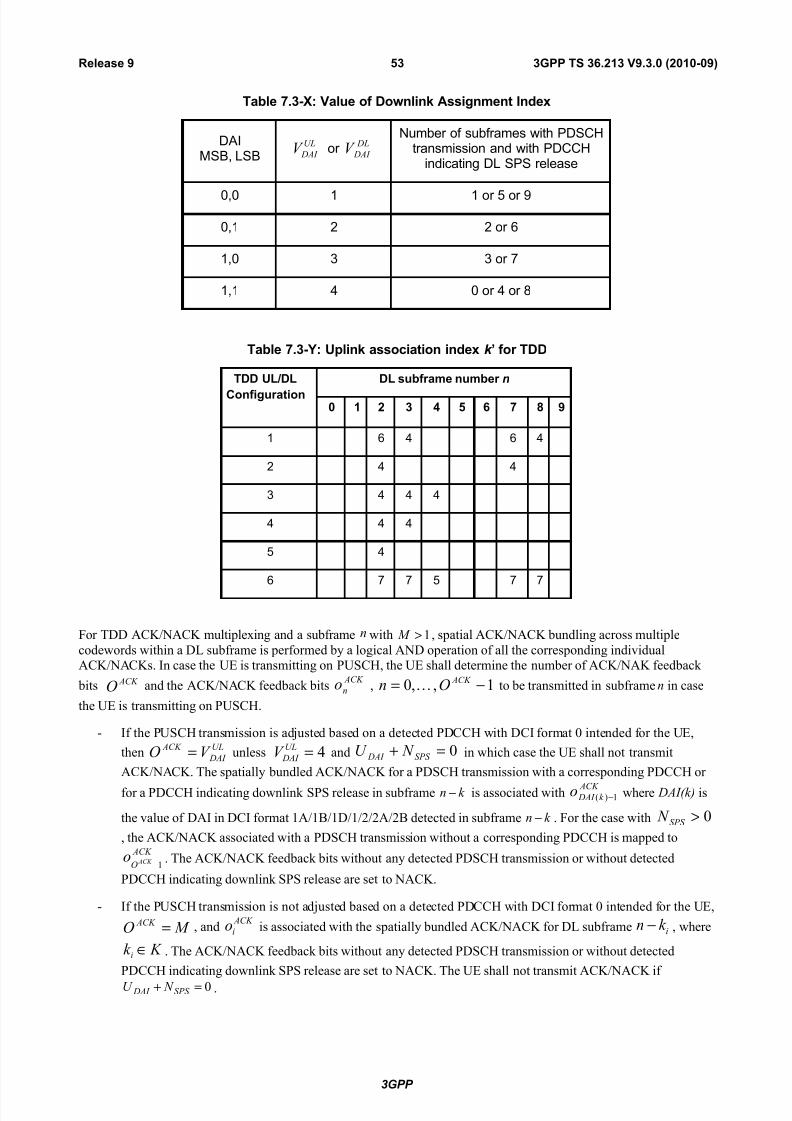
7/29/2019 LTE Procedures 36213-930
http://slidepdf.com/reader/full/lte-procedures-36213-930 53/80
Table 7.3-X: Value of Downlink Assignment Index
DAIMSB, LSB
UL
DAI V or DL
DAI V Number of subframes with PDSCH
transmission and with PDCCHindicating DL SPS release
0,0 1 1 or 5 or 9
0,1 2 2 or 6
1,0 3 3 or 7
1,1 4 0 or 4 or 8
Table 7.3-Y: Uplink association index k ’ for TDD
TDD UL/DL
Configuration
DL subframe number n
0 1 2 3 4 5 6 7 8 9
1 6 4 6 4
2 4 4
3 4 4 4
4 4 4
5 4
6 7 7 5 7 7
For TDD ACK/NACK multiplexing and a subframe n with 1> M , spatial ACK/NACK bundling across multiple
codewords within a DL subframe is performed by a logical AND operation of all the corresponding individualACK/NACKs. In case the UE is transmitting on PUSCH, the UE shall determine the number of ACK/NAK feedback
bits ACK O and the ACK/NACK feedback bits ACK
no , 1,,0 −= ACK On to be transmitted in subframe n in case
the UE is transmitting on PUSCH.
- If the PUSCH transmission is adjusted based on a detected PDCCH with DCI format 0 intended for the UE,
thenUL
DAI
ACK V O = unless 4=UL
DAI V and 0=+ SPS DAI N U in which case the UE shall not transmit
ACK/NACK. The spatially bundled ACK/NACK for a PDSCH transmission with a corresponding PDCCH or
for a PDCCH indicating downlink SPS release in subframe k n − is associated with ACK k DAI o 1)( − where DAI(k) is
the value of DAI in DCI format 1A/1B/1D/1/2/2A/2B detected in subframe k n − . For the case with 0>SPS N
, the ACK/NACK associated with a PDSCH transmission without a corresponding PDCCH is mapped to ACK
O ACK o1− . The ACK/NACK feedback bits without any detected PDSCH transmission or without detected
PDCCH indicating downlink SPS release are set to NACK.
- If the PUSCH transmission is not adjusted based on a detected PDCCH with DCI format 0 intended for the UE,
M O ACK = , and ACK
io is associated with the spatially bundled ACK/NACK for DL subframe ik n − , where
K k i ∈ . The ACK/NACK feedback bits without any detected PDSCH transmission or without detected
PDCCH indicating downlink SPS release are set to NACK. The UE shall not transmit ACK/NACK if
0=+ SPS DAI N U .
3GPP
3GPP TS 36.213 V9.3.0 (2010-09)53Release 9

7/29/2019 LTE Procedures 36213-930
http://slidepdf.com/reader/full/lte-procedures-36213-930 54/80
For TDD when both ACK/NACK and SR are transmitted in the same sub-frame, a UE shall transmit the bundledACK/NACK or the multiple ACK/NAK responses (according to section 10.1) on its assigned ACK/NACK PUCCH
resources for a negative SR transmission. For a positive SR, the UE shall transmit )1(),0( bb on its assigned SR PUCCH
resource using PUCCH format 1b according to section 5.4.1 in [3]. The value of )1(),0( bb are generated according to
Table 7.3-1 from the SPS DAI N U + ACK/NACK responses including ACK in response to PDCCH indicating downlink
SPS release by spatial ACK/NAK bundling across multiple codewords within each PDSCH transmission. For TDD UL-DL configurations 1-6, if 0> DAI U and ( ) 14mod1 +−≠ DAI
DL DAI U V , the UE detects that at least one downlink
assignment has been missed.
Table 7.3-1: Mapping between multiple ACK/NACK responses and )1(),0( bb
Number of ACK among multiple ( SPS DAI N U + ) ACK/NACK
responses)1(),0( bb
0 or None (UE detect at least one DL assignment is missed) 0, 0
1 1, 1
2 1, 0
3 0, 1
4 1, 1
5 1, 0
6 0, 1
7 1, 1
8 1, 0
9 0, 1
For TDD when both ACK/NACK and CQI/PMI or RI are configured to be transmitted in the same sub-frame on
PUCCH, a UE shall transmit CQI/PMI or RI and )1(),0( bb using PUCCH format 2b for normal CP or PUCCH format 2
for extended CP, according to section 5.2.3.4 in [4] with 10 ,aa ′′′′ replaced by )1(),0( bb . The value of )1(),0( bb are
generated according to Table 7.3-1 from the SPS DAI N U + ACK/NACK responses including ACK in response to
PDCCH indicating downlink SPS release by spatial ACK/NACK bundling across multiple codewords within each
PDSCH transmission. For TDD UL-DL configurations 1-6, if 0> DAI U and ( ) 14mod1 +−≠ DAI DL
DAI U V , the UE detects
that at least one downlink assignment has been missed.
When only ACK/NACK or only a positive SR is transmitted a UE shall use PUCCH Format 1a or 1b for theACK/NACK resource and PUCCH Format 1 for the SR resource as defined in section 5.4.1 in [3].
8 Physical uplink shared channel related procedures
For FDD, there shall be 8 HARQ processes in the uplink for non-subframe bundling operation, i.e. normal HARQ
operation, and 4 HARQ processes in the uplink for subframe bundling operation. The subframe bundling operation isconfigured by the parameter ttiBundling provided by higher layers.
In case higher layers configure the use of subframe bundling for FDD and TDD, the subframe bundling operation isonly applied to UL-SCH, such that four consecutive uplink subframes are used.
3GPP
3GPP TS 36.213 V9.3.0 (2010-09)54Release 9

7/29/2019 LTE Procedures 36213-930
http://slidepdf.com/reader/full/lte-procedures-36213-930 55/80
For FDD and normal HARQ operation, the UE shall upon detection of a PDCCH with DCI format 0 and/or a PHICHtransmission in subframe n intended for the UE, adjust the corresponding PUSCH transmission in subframe n+4
according to the PDCCH and PHICH information.
For FDD and subframe bundling operation, the UE shall upon detection of a PDCCH with DCI format 0 in subframe n
intended for the UE, and/or a PHICH transmission in subframe n-5 intended for the UE, adjust the corresponding first
PUSCH transmission in the bundle in subframe n+4 according to the PDCCH and PHICH information.
For FDD and TDD, the NDI as signalled on PDCCH, the RV as determined in section 8.6.1, and the TBS as determined
in section 8.6.2, shall be delivered to higher layers.
For TDD, the number of HARQ processes shall be determined by the DL/UL configuration (Table 4.2-2 of [3]), asindicated in table 8-1.
Table 8-1: Number of synchronous UL HARQ processes for TDD
TDD UL/DLconfiguration
Number of HARQ processes for normal HARQ operation
Number of HARQ processes for subframe bundling operation
0 7 3
1 4 2
2 2 N/A3 3 N/A
4 2 N/A
5 1 N/A
6 6 3
For TDD UL/DL configurations 1-6 and normal HARQ operation, the UE shall upon detection of a PDCCH with DCIformat 0 and/or a PHICH transmission in subframe n intended for the UE, adjust the corresponding PUSCH
transmission in subframe n+k , with k given in Table 8-2, according to the PDCCH and PHICH information.
For TDD UL/DL configuration 0 and normal HARQ operation the UE shall upon detection of a PDCCH with DCI
format 0 and/or a PHICH transmission in subframe n intended for the UE, adjust the corresponding PUSCHtransmission in subframe n+k if the MSB of the UL index in the DCI format 0 is set to 1 or PHICH is received in
subframe n=0 or 5 in the resource corresponding to 0 PHICH I = , as defined in Section 9.1.2, with k given in Table 8-2.
If, for TDD UL/DL configuration 0 and normal HARQ operation, the LSB of the UL index in the DCI format 0 is set to
1 in subframe n or a PHICH is received in subframe n=0 or 5 in the resource corresponding to 1 PHICH I = , as defined in
Section 9.1.2, or PHICH is received in subframe n=1 or 6, the UE shall adjust the corresponding PUSCH transmission
in subframe n+7 . If, for TDD UL/DL configuration 0, both the MSB and LSB of the UL index in the DCI format 0 areset in subframe n, the UE shall adjust the corresponding PUSCH transmission in both subframes n+ k and n+7 , with k
given in Table 8-2
For TDD UL/DL configurations 1 and 6 and subframe bundling operation, the UE shall upon detection of a PDCCH
with DCI format 0 in subframe n intended for the UE, and/or a PHICH transmission intended for the UE in subframe n-
l with l given in Table 8-2a, adjust the corresponding first PUSCH transmission in the bundle in subframe n+k , with k
given in Table 8-2 , according to the PDCCH and PHICH information.
For TDD UL/DL configuration 0 and subframe bundling operation, the UE shall upon detection of a PDCCH with DCI
format 0 in subframe n intended for the UE, and/or a PHICH transmission intended for the UE in subframe n-l with l
given in Table 8-2a, adjust the corresponding first PUSCH transmission in the bundle in subframe n+k , if the MSB of
the UL index in the DCI format 0 is set to 1 or if 0 PHICH I = , as defined in Section 9.1.2, with k given in Table 8-2,
according to the PDCCH and PHICH information. If, for TDD UL/DL configuration 0 and subframe bundling
operation, the LSB of the UL index in the DCI format 0 is set to 1 in subframe n or if 1 PHICH I = , as defined in Section
9.1.2, the UE shall adjust the corresponding first PUSCH transmission in the bundle in subframe n+7 , according to the
PDCCH and PHICH information.
Table 8-2 k for TDD configurations 0-6
TDD UL/DLConfiguratio
DL subframe number n
0 1 2 3 4 5 6 7 8 9
3GPP
3GPP TS 36.213 V9.3.0 (2010-09)55Release 9

7/29/2019 LTE Procedures 36213-930
http://slidepdf.com/reader/full/lte-procedures-36213-930 56/80
n
0 4 6 4 6
1 6 4 6 4
2 4 4
3 4 4 4
4 4 4
5 4
6 7 7 7 7 5
Table 8-2a l for TDD configurations 0, 1 and 6
TDD UL/DLConfiguratio
n
DL subframe number n
0 1 2 3 4 5 6 7 8 9
0 9 6 9 6
1 2 3 2 3
6 5 5 6 6 8
If a UE is configured by higher layers to decode PDCCHs with the CRC scrambled by the C-RNTI, the UE shall decode
the PDCCH according to the combination defined in table 8-3 and transmit the corresponding PUSCH. The scrambling
initialization of this PUSCH corresponding to these PDCCHs and the PUSCH retransmission for the same transport block is by C-RNTI.
Table 8-3: PDCCH configured by C-RNTI
DCI format Search Space
DCI format 0 Common andUE specific by C-RNTI
If a UE is configured by higher layers to decode PDCCHs with the CRC scrambled by the C-RNTI and is also
configured to receive random access procedures initiated by PDCCH orders, the UE shall decode the PDCCH accordingto the combination defined in table 8-4.
Table 8-4: PDCCH configured as PDCCH order to initiate random access procedure
DCI format Search Space
DCI format 1A Common andUE specific by C-RNTI
If a UE is configured by higher layers to decode PDCCHs with the CRC scrambled by the SPS C-RNTI, the UE shalldecode the PDCCH according to the combination defined in table 8-5 and transmit the corresponding PUSCH. The
scrambling initialization of this PUSCH corresponding to these PDCCHs and PUSCH retransmission for the sametransport block is by SPS C-RNTI. The scrambling initialization of initial transmission of this PUSCH without a
corresponding PDCCH and the PUSCH retransmission for the same transport block is by SPS C-RNTI.
3GPP
3GPP TS 36.213 V9.3.0 (2010-09)56Release 9

7/29/2019 LTE Procedures 36213-930
http://slidepdf.com/reader/full/lte-procedures-36213-930 57/80
Table 8-5: PDCCH configured by SPS C-RNTI
DCI format Search Space
DCI format 0 Common andUE specific by C-RNTI
If a UE is configured by higher layers to decode PDCCHs with the CRC scrambled by the Temporary C-RNTIregardless of whether UE is configured or not configured to decode PDCCHs with the CRC scrambled by the C-RNTI,
the UE shall decode the PDCCH according to the combination defined in table 8-6 and transmit the correspondingPUSCH. The scrambling initialization of PUSCH corresponding to these PDCCH is by Temporary C-RNTI.
If a Temporary C-RNTI is set by higher layers, the scrambling of PUSCH corresponding to the Random AccessResponse Grant in Section 6.2 and the PUSCH retransmission for the same transport block is by Temporary C-RNTI.
Else, the scrambling of PUSCH corresponding to the Random Access Response Grant in Section 6.2 and the PUSCHretransmission for the same transport block is by C-RNTI.
Table 8-6: PDCCH configured by Temporary C-RNTI
DCI format Search Space
DCI format 0 Common
If a UE is configured by higher layers to decode PDCCHs with the CRC scrambled by the TPC-PUCCH-RNTI, the UE
shall decode the PDCCH according to the combination defined in table 8-7. The notation 3/3A implies that the UE shallreceive either DCI format 3 or DCI format 3A depending on the configuration.
Table 8-7: PDCCH configured by TPC-PUCCH-RNTI
DCI format Search SpaceDCI format 3/3A Common
If a UE is configured by higher layers to decode PDCCHs with the CRC scrambled by the TPC-PUSCH-RNTI, the UE
shall decode the PDCCH according to the combination defined in table 8.8. The notation 3/3A implies that the UE shallreceive either DCI format 3 or DCI format 3A depending on the configuration.
Table 8-8: PDCCH configured by TPC-PUSCH-RNTI
DCI format Search SpaceDCI format 3/3A Common
8.1 Resource Allocation for PDCCH DCI Format 0
The resource allocation information indicates to a scheduled UE a set of contiguously allocated virtual resource block
indices denoted by VRBn . A resource allocation field in the scheduling grant consists of a resource indication value
( RIV ) corresponding to a starting resource block ( START RB ) and a length in terms of contiguously allocated resource
blocks ( CRBs L ≥ 1). The resource indication value is defined by
if 2/)1(ULRBCRBs N L ≤− then
STARTCRBsULRB )1( RB L N RIV +−=
else
)1()1( STARTULRBCRBs
ULRB
ULRB RB N L N N RIV −−++−=
A UE shall discard PUSCH resource allocation in the corresponding PDCCH with DCI format 0 if consistent controlinformation is not detected.
3GPP
3GPP TS 36.213 V9.3.0 (2010-09)57Release 9

7/29/2019 LTE Procedures 36213-930
http://slidepdf.com/reader/full/lte-procedures-36213-930 58/80
8.2 UE sounding procedure
The following Sounding Reference Symbol (SRS) parameters are UE specific semi-statically configurable by higher
layers:
• Transmission comb TC k , as defined in Section 5.5.3.2 of [3]
• Starting physical resource block assignment RRC n , as defined in Section 5.5.3.2 of [3]
• duration: single or indefinite (until disabled), as defined in [11]
• srs-ConfigIndex ISRS for SRS periodicity and SRS subframe offset offset T , as defined in Table 8.2-1 and Table
8.2-2
• SRS bandwidth SRS B , as defined in Section 5.5.3.2 of [3]
• Frequency hopping bandwidth, hopb , as defined in Section 5.5.3.2 of [3]
• Cyclic shiftcs
SRS n , as defined in Section 5.5.3.1 of [3]
The cell specific SRS transmission bandwidths SRS C are configured by higher layers. The allowable values are given in
Section 5.5.3.2 of [3].
The cell specific SRS transmission sub-frames are configured by higher layers. The allowable values are given in
Section 5.5.3.3 of [3].
When antenna selection is enabled for a UE that supports transmit antenna selection, the index ( )SRS na , of the UE
antenna that transmits the SRS at time nSRS is given by
( ) 2modSRS SRS nna = , for both partial and full sounding bandwidth, and when frequency hopping is disabled (i.e.,
SRS hop Bb ≥ ),
( )
oddiswhen 2mod
eveniswhen2mod/2/)(
⋅++
= K n
K K nnnna
SRS
SRS SRS SRS SRS
β ,
otherwise 0
04modwhere1
=
=K
β
when frequency hopping is enabled (i.e., SRS hop Bb < ),
where values BSRS, bhop, N b, and nSRS are given in Section 5.5.3.2 of [3], and ∏=
=SRS
hop
B
bb
b N K '
' (where 1=hopb N regardless
of the b N value), except when a single SRS transmission is configured for the UE.
For TDD, when one SC-FDMA symbol exists in UpPTS, it can be used for SRS transmission. When two SC-FDMA
symbols exist in UpPTS, both can be used for SRS transmission and both can be assigned to the same UE.
A UE shall not transmit SRS whenever SRS and PUCCH format 2/2a/2b transmissions happen to coincide in the same
subframe.
A UE shall not transmit SRS whenever SRS transmission and PUCCH transmission carrying ACK/NACK and/or
positive SR happen to coincide in the same subframe if the parameter ackNackSRS-SimultaneousTransmission is FALSE . A UE shall transmit SRS whenever SRS transmission and PUCCH transmission carrying ACK/NACK and/or
positive SR happen to coincide in the same subframe if the parameter ackNackSRS-SimultaneousTransmission is TRUE .
In UpPTS, whenever SRS transmission instance overlaps with the PRACH region for preamble format 4 or exceeds the
range of uplink system bandwidth configured in the cell, the UE shall not transmit SRS.
3GPP
3GPP TS 36.213 V9.3.0 (2010-09)58Release 9

7/29/2019 LTE Procedures 36213-930
http://slidepdf.com/reader/full/lte-procedures-36213-930 59/80
The parameter ackNackSRS-SimultaneousTransmission provided by higher layers determines if a UE is configured tosupport the transmission of ACK/NACK on PUCCH and SRS in one subframe. If it is configured to support the
transmission of ACK/NACK on PUCCH and SRS in one subframe, then in the cell specific SRS subframes UE shalltransmit ACK/NACK and SR using the shortened PUCCH format as defined in Section 5.4.1 of [3], where the
ACK/NACK or the SR symbol corresponding to the SRS location is punctured. This shortened PUCCH format shall beused in a cell specific SRS subframe even if the UE does not transmit SRS in that subframe. The cell specific SRS
subframes are defined in Section 5.5.3.3 of [3]. Otherwise, the UE shall use the normal PUCCH format 1/1a/1b asdefined in Section 5.4.1 of [3] for the transmission of ACK/NACK and SR.
The UE specific SRS configuration for SRS periodicity, SRST , and SRS subframe offset, offset T , is defined in Table 8.2-1
and Table 8.2-2, for FDD and TDD, respectively. The periodicity SRST of the SRS transmission is selected from the set
{2, 5, 10, 20, 40, 80, 160, 320} ms or subframes. For the SRS periodicity SRST of 2 ms in TDD, two SRS resources are
configured in a half frame containing UL subframe(s).
SRS transmission instances for TDD with 2SRS >T and for FDD are the subframes satisfying
0mod)10( SRSSRS =−+⋅ T T k n offset f , where for FDD { }9,...,1,0SRS
=k is the subframe index within the frame, for TDD
SRSk is defined in Table 8.2-3. The SRS transmission instances for TDD with 2SRS =T are the subframes satisfying
05mod)( SRS =− offset T k .
A UE shall not transmit SRS whenever SRS and a PUSCH transmission corresponding to a Random Access Response
Grant or a retransmission of the same transport block as part of the contention based random access procedure coincidein the same subframe.
Table 8.2-1: UE Specific SRS Periodicity SRST and Subframe Offset Configuration offset T , FDD
SRS Configuration Index ISRS SRS Periodicity SRST (ms) SRS Subframe Offset offset T
0 – 1 2 ISRS
2 – 6 5 ISRS – 2
7 – 16 10 ISRS – 7
17 – 36 20 ISRS – 17
37 – 76 40 ISRS – 37
77 – 156 80 ISRS – 77
157 – 316 160 ISRS – 157
317 – 636 320 ISRS – 317
637 – 1023 reserved reserved
Table 8.2-2: UE Specific SRS Periodicity SRST and Subframe Offset Configuration offset T , TDD
SRS Configuration Index ISRS SRS Periodicity SRST (ms) SRS Subframe Offset offset T
0 2 0, 1
1 2 0, 2
2 2 1, 2
3GPP
3GPP TS 36.213 V9.3.0 (2010-09)59Release 9
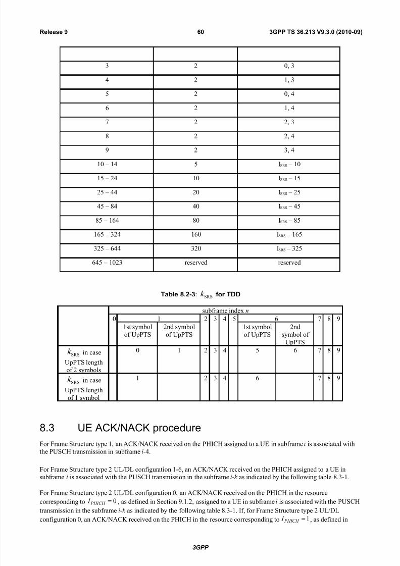
7/29/2019 LTE Procedures 36213-930
http://slidepdf.com/reader/full/lte-procedures-36213-930 60/80
3 2 0, 3
4 2 1, 3
5 2 0, 4
6 2 1, 4
7 2 2, 3
8 2 2, 4
9 2 3, 4
10 – 14 5 ISRS – 10
15 – 24 10 ISRS – 15
25 – 44 20 ISRS – 25
45 – 84 40 ISRS – 45
85 – 164 80 ISRS – 85
165 – 324 160 ISRS – 165
325 – 644 320 ISRS – 325
645 – 1023 reserved reserved
Table 8.2-3: SRSk for TDD
subframe index n
0 1 2 3 4 5 6 7 8 9
1st symbol
of UpPTS
2nd symbol
of UpPTS
1st symbol
of UpPTS
2nd
symbol of UpPTS
SRSk in case
UpPTS lengthof 2 symbols
0 1 2 3 4 5 6 7 8 9
SRSk in case
UpPTS length
of 1 symbol
1 2 3 4 6 7 8 9
8.3 UE ACK/NACK procedure
For Frame Structure type 1, an ACK/NACK received on the PHICH assigned to a UE in subframe i is associated withthe PUSCH transmission in subframe i-4.
For Frame Structure type 2 UL/DL configuration 1-6, an ACK/NACK received on the PHICH assigned to a UE insubframe i is associated with the PUSCH transmission in the subframe i-k as indicated by the following table 8.3-1.
For Frame Structure type 2 UL/DL configuration 0, an ACK/NACK received on the PHICH in the resourcecorresponding to 0 PHICH I = , as defined in Section 9.1.2, assigned to a UE in subframe i is associated with the PUSCH
transmission in the subframe i-k as indicated by the following table 8.3-1. If, for Frame Structure type 2 UL/DL
configuration 0, an ACK/NACK received on the PHICH in the resource corresponding to 1 PHICH I = , as defined in
3GPP
3GPP TS 36.213 V9.3.0 (2010-09)60Release 9

7/29/2019 LTE Procedures 36213-930
http://slidepdf.com/reader/full/lte-procedures-36213-930 61/80
Section 9.1.2, assigned to a UE in subframe i is associated with the PUSCH transmission in the subframe i-6.
Table 8.3-1 k for TDD configurations 0-6
TDD UL/DL
Configuration
DL subframe number i
0 1 2 3 4 5 6 7 8 9
0 7 4 7 4
1 4 6 4 6
2 6 6
3 6 6 6
4 6 6
5 6
6 6 4 7 4 6
The physical layer in the UE shall deliver indications to the higher layers as follows:
For downlink subframe i, if a transport block was transmitted in the associated PUSCH subframe then:
- if ACK is decoded on the PHICH in subframe i, ACK shall be delivered to the higher layers;
- else NACK shall be delivered to the higher layers.
8.4 UE PUSCH Hopping procedure
The UE shall perform PUSCH frequency hopping if the single bit frequency hopping (FH) field in a correspondingPDCCH with DCI format 0 is set to 1 otherwise no PUSCH frequency hopping is performed.
A UE performing PUSCH frequency hopping shall determine its PUSCH resource allocation (RA) for the first slot of a
subframe (S1) including the lowest index PRB ( )(1
nnS
PRB ) in subframe n from the resource allocation field in the latest
PDCCH with DCI format 0 for the same transport block. If there is no PDCCH for the same transport block, the UE
shall determine its hopping type based on
- the hopping information in the most recent semi-persistent scheduling assignment PDCCH, when the initialPUSCH for the same transport block is semi-persistently scheduled or
- the random access response grant for the same transport block, when the PUSCH is initiated by the random
access response grant.
The resource allocation field in DCI format 0 excludes either 1 or 2 bits used for hopping information as indicated by
Table 8.4-1 below where the number of PUSCH resource blocks is defined as
( )
>−
=
−−
=
hoppingPUSCH1 N2Type~
hoppingPUSCH1 N2Type
hoppingPUSCH1Type2mod~
sb
sb
HO
RB
UL
RB
UL
RB
UL
RB
HO
RB
UL
RB
PUSCH
RB
N N
N
N N N
N
3GPP
3GPP TS 36.213 V9.3.0 (2010-09)61Release 9

7/29/2019 LTE Procedures 36213-930
http://slidepdf.com/reader/full/lte-procedures-36213-930 62/80
For type 1 and type 2 PUSCH hopping, 1~ HO
RBHORB += N N if HO
RB N is an odd number where HO
RB N defined in [3].
HORB
HORB
~ N N = in other cases. The size of the resource allocation field in DCI format 0 after excluding either 1 or 2 bits
shall be hopUL N N N y _
UL
RB
UL
RB2 )2/)1((log −+= , where N UL_hop = 1 or 2 bits. The number of contiguous RBs
that can be assigned to a type-1 hopping user is limited to
UL
RB/2 N y . The number of contiguous RBs that can be
assigned to a type-2 hopping user is limited to min
(UL
RB/2 N y , sb N N /PUSCH
RB), where the number of sub-bands
sb N is given by higher layers.
A UE performing PUSCH frequency hopping shall use one of two possible PUSCH frequency hopping types based onthe hopping information. PUSCH hopping type 1 is described in section 8.4.1 and type 2 is described in section 8.4.2.
Table 8.4-1: Number of Hopping Bits NUL_hop vs. System Bandwidth
System BWUL RB N
#Hopping bits for 2nd slot RA
(N UL_hop)
6-49 1
50-110 2
The parameter Hopping-mode provided by higher layers determines if PUSCH frequency hopping is “inter-subframe”
or “intra and inter-subframe”.
8.4.1 Type 1 PUSCH Hopping
For PUSCH hopping type 1 the hopping bit or bits indicated in Table 8.4-1 determine )(~ in PRB as defined in Table 8.4-2.
The lowest index PRB ( 1 ( )S PRBn i ) of the 1st slot RA in subframe i is defined as 1 1 HO
RB( ) ( ) / 2S S PRB PRBn i n i N = + %% , where
1 ( )S PRB START n i RB= , and START RB is obtained from the uplink scheduling grant as in Section 8.4 and Section 8.1.
The lowest index PRB ( )(in PRB ) of the 2nd slot RA in subframe i is defined as HORB( ) ( ) / 2 PRB PRBn i n i N = + %% .
The set of physical resource blocks to be used for PUSCH transmission are CRBs L contiguously allocated resource
blocks from PRB index 1 ( )S PRBn i for the 1st slot, and from PRB index )(in PRB for the 2nd slot, respectively, where CRBs L
is obtained from the uplink scheduling grant as in Section 8.4 and Section 8.1.
If the Hopping-mode is "inter-subframe", the 1st slot RA is applied to even CURRENT_TX_NB, and the 2nd slot RA is
applied to odd CURRENT_TX_NB, where CURRENT_TX_NB is defined in [8].
8.4.2 Type 2 PUSCH Hopping
In PUSCH hopping type 2 the set of physical resource blocks to be used for transmission in slot sn is given by the
scheduling grant together with a predefined pattern according to [3] section 5.3.4. If the system frame number is not
acquired by the UE yet, the UE shall not transmit PUSCH with type-2 hopping and 1 sb N > for TDD, where sb N is
defined in [3].
3GPP
3GPP TS 36.213 V9.3.0 (2010-09)62Release 9

7/29/2019 LTE Procedures 36213-930
http://slidepdf.com/reader/full/lte-procedures-36213-930 63/80
Table 8.4-2: PDCCH DCI Format 0 Hopping Bit Definition
System BWUL RB N
Number of Hopping bits
Information inhopping bits
)(~ in PRB
6 – 49 10 PUSCH
RBS
PRB PUSCH RB N in N mod)(~2/ 1
+ ,
1 Type 2 PUSCH Hopping
50 – 110 2
00 PUSCH RB
S PRB
PUSCH RB N in N mod)(~4/ 1
+
01 PUSCH RB
S PRB
PUSCH RB N in N mod)(~4/ 1
+−
10 PUSCH RB
S PRB
PUSCH RB N in N mod)(~2/ 1
+
11 Type 2 PUSCH Hopping
8.5 UE Reference Symbol procedureIf UL sequence hopping is configured in the cell, it applies to all reference symbols (SRS, PUSCH and PUCCH RS).
8.6 Modulation order, redundancy version and transport blocksize determination
To determine the modulation order, redundancy version and transport block size for the physical uplink shared channel,the UE shall first
− read the “modulation and coding scheme and redundancy version” field ( MCS I ), and
− check the “CQI request” bit, and
− compute the total number of allocated PRBs ( PRB N ) based on the procedure defined in Section 8.1, and
− compute the number of coded symbols for control information.
8.6.1 Modulation order and redundancy version determination
For 280 MCS ≤≤ I , the modulation order ( mQ ) is determined as follows:
− If the UE is capable of supporting 64QAM in PUSCH and has not been configured by higher layers to transmitonly QPSK and 16QAM, the modulation order is given by
'
mQ in Table 8.6.1-1.
− If the UE is not capable of supporting 64QAM in PUSCH or has been configured by higher layers to transmit
only QPSK and 16QAM,'
mQ is first read from Table 8.6.1-1. The modulation order is set to ),4min( '
mm QQ = .
− If the parameter ttiBundling provided by higher layers is set to TRUE , then the resource allocation size is
restricted to 3PRB ≤ N and the modulation order is set to 2=mQ .
For 3129 MCS ≤≤ I , if 29MCS = I , the “CQI request” bit in DCI format 0 is set to 1 and 4PRB ≤ N , the modulation order
is set to 2=mQ . Otherwise, the modulation order shall be determined from the DCI transported in the latest PDCCH
with DCI format 0 for the same transport block using 280MCS
≤≤ I . If there is no PDCCH with DCI format 0 for the
same transport block using 280 MCS ≤≤ I , the modulation order shall be determined from
3GPP
3GPP TS 36.213 V9.3.0 (2010-09)63Release 9
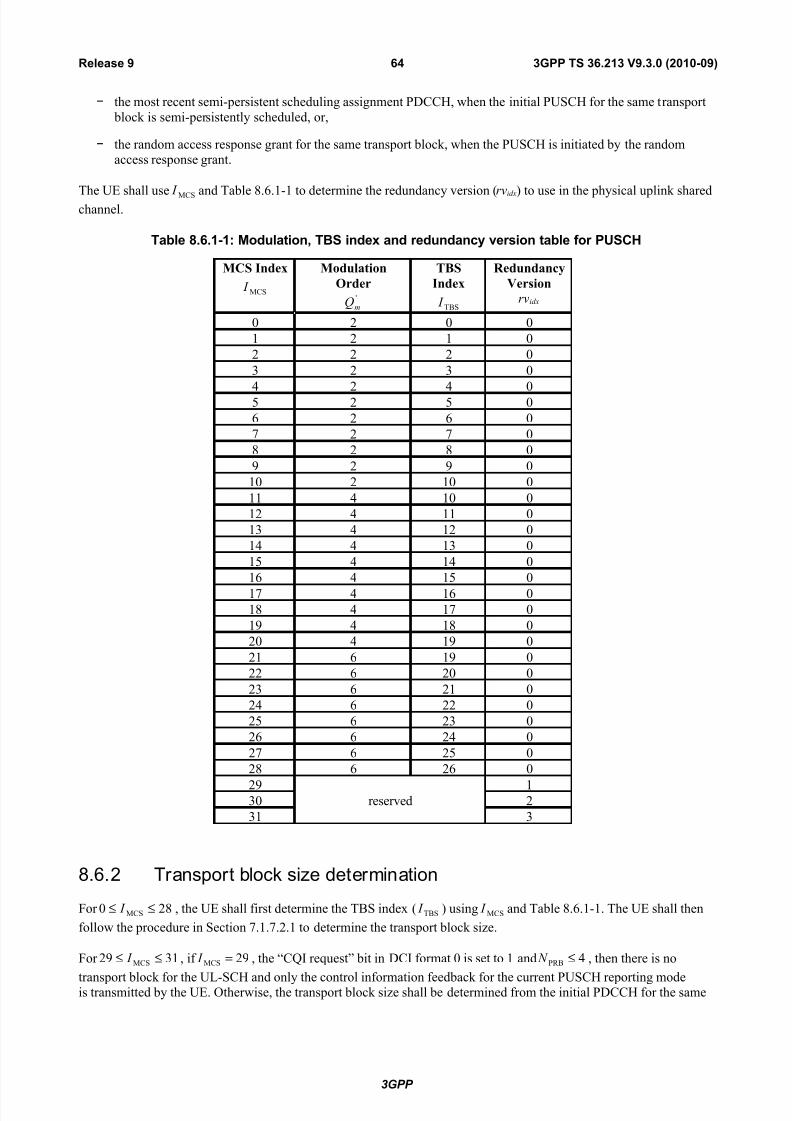
7/29/2019 LTE Procedures 36213-930
http://slidepdf.com/reader/full/lte-procedures-36213-930 64/80
− the most recent semi-persistent scheduling assignment PDCCH, when the initial PUSCH for the same transport
block is semi-persistently scheduled, or,
− the random access response grant for the same transport block, when the PUSCH is initiated by the randomaccess response grant.
The UE shall use MCS I and Table 8.6.1-1 to determine the redundancy version (rvidx) to use in the physical uplink sharedchannel.
Table 8.6.1-1: Modulation, TBS index and redundancy version table for PUSCH
MCS Index
MCS I
Modulation
Order'
mQ
TBS
Index
TBS I
Redundancy
Version
rvidx
0 2 0 0
1 2 1 0
2 2 2 0
3 2 3 0
4 2 4 05 2 5 0
6 2 6 0
7 2 7 0
8 2 8 0
9 2 9 0
10 2 10 0
11 4 10 0
12 4 11 0
13 4 12 0
14 4 13 0
15 4 14 0
16 4 15 0
17 4 16 018 4 17 0
19 4 18 0
20 4 19 0
21 6 19 0
22 6 20 0
23 6 21 0
24 6 22 0
25 6 23 0
26 6 24 0
27 6 25 0
28 6 26 0
29reserved
130 2
31 3
8.6.2 Transport block size determination
For 280 MCS ≤≤ I , the UE shall first determine the TBS index ( TBS I ) using MCS I and Table 8.6.1-1. The UE shall then
follow the procedure in Section 7.1.7.2.1 to determine the transport block size.
For 3129 MCS ≤≤ I , if 29MCS = I , the “CQI request” bit in DCI format 0 is set to 1 and 4PRB ≤ N , then there is no
transport block for the UL-SCH and only the control information feedback for the current PUSCH reporting modeis transmitted by the UE. Otherwise, the transport block size shall be determined from the initial PDCCH for the same
3GPP
3GPP TS 36.213 V9.3.0 (2010-09)64Release 9

7/29/2019 LTE Procedures 36213-930
http://slidepdf.com/reader/full/lte-procedures-36213-930 65/80
transport block using 280 MCS ≤≤ I . If there is no initial PDCCH with DCI format 0 for the same transport block using
280 MCS ≤≤ I , the transport block size shall be determined from
− the most recent semi-persistent scheduling assignment PDCCH, when the initial PUSCH for the same transport
block is semi-persistently scheduled, or,
− the random access response grant for the same transport block, when the PUSCH is initiated by the randomaccess response grant.
8.6.3 Control information MCS offset determination
ACK HARQ
offset
−β , RI
offset β andCQI
offset β shall be configured to values according to Table 8.6.3-1,2,3 with the higher layer
signalled indexes ACK HARQ
offset I −,
RI
offset I , andCQI
offset I , respectively.
Table 8.6.3-1: Mapping of HARQ-ACK offset values and the index signalled by higher layers
ACK HARQ
offset I − ACK HARQ
offset
−β
0 2.000
1 2.500
2 3.125
3 4.000
4 5.000
5 6.250
6 8.000
7 10.000
8 12.625
9 15.875
10 20.000
11 31.000
12 50.000
13 80.000
14 126.000
15 reserved
Table 8.6.3-2: Mapping of RI offset values and the index signalled by higher layers
RI
offset I RI
offset β
0 1.250
1 1.625
3GPP
3GPP TS 36.213 V9.3.0 (2010-09)65Release 9

7/29/2019 LTE Procedures 36213-930
http://slidepdf.com/reader/full/lte-procedures-36213-930 66/80
2 2.000
3 2.500
4 3.125
5 4.000
6 5.000
7 6.250
8 8.000
9 10.000
10 12.625
11 15.875
12 20.000
13 reserved
14 reserved
15 reserved
Table 8.6.3-3: Mapping of CQI offset values and the index signalled by higher layers
CQI
offset I CQI
offset β
0 reserved
1 reserved
2 1.125
3 1.250
4 1.375
5 1.625
6 1.750
7 2.000
8 2.2509 2.500
10 2.875
11 3.125
12 3.500
13 4.000
14 5.000
15 6.250
3GPP
3GPP TS 36.213 V9.3.0 (2010-09)66Release 9
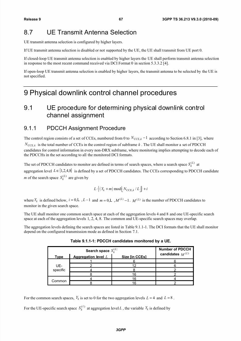
7/29/2019 LTE Procedures 36213-930
http://slidepdf.com/reader/full/lte-procedures-36213-930 67/80
8.7 UE Transmit Antenna Selection
UE transmit antenna selection is configured by higher layers.
If UE transmit antenna selection is disabled or not supported by the UE, the UE shall transmit from UE port 0.
If closed-loop UE transmit antenna selection is enabled by higher layers the UE shall perform transmit antenna selectionin response to the most recent command received via DCI Format 0 in section 5.3.3.2 [4].
If open-loop UE transmit antenna selection is enabled by higher layers, the transmit antenna to be selected by the UE is
not specified.
9 Physical downlink control channel procedures
9.1 UE procedure for determining physical downlink controlchannel assignment
9.1.1 PDCCH Assignment Procedure
The control region consists of a set of CCEs, numbered from 0 to 1,CCE −k N according to Section 6.8.1 in [3], where
k N ,CCE is the total number of CCEs in the control region of subframe k . The UE shall monitor a set of PDCCH
candidates for control information in every non-DRX subframe, where monitoring implies attempting to decode each of
the PDCCHs in the set according to all the monitored DCI formats.
The set of PDCCH candidates to monitor are defined in terms of search spaces, where a search space)( L
k S at
aggregation level { }8,4,2,1∈ L is defined by a set of PDCCH candidates. The CCEs corresponding to PDCCH candidate
m of the search space
)( L
k S are given by
( ){ }CCE,mod /k k L Y m N L i ⋅ + +
where k Y is defined below, 0, , 1i L= −L and ( )0, , 1 Lm M = −L . )( L M is the number of PDCCH candidates to
monitor in the given search space.
The UE shall monitor one common search space at each of the aggregation levels 4 and 8 and one UE-specific searchspace at each of the aggregation levels 1, 2, 4, 8. The common and UE-specific search spaces may overlap.
The aggregation levels defining the search spaces are listed in Table 9.1.1-1. The DCI formats that the UE shall monitor depend on the configured transmission mode as defined in Section 7.1.
Table 9.1.1-1: PDCCH candidates monitored by a UE.
Search space)( L
k S Number of PDCCH
candidates )( L M
Type Aggregation level L Size [in CCEs]
UE-specific
1 6 6
2 12 6
4 8 2
8 16 2
Common4 16 4
8 16 2
For the common search spaces, k Y is set to 0 for the two aggregation levels 4= L and 8= L .
For the UE-specific search space)( L
k S at aggregation level L , the variable k Y is defined by
3GPP
3GPP TS 36.213 V9.3.0 (2010-09)67Release 9

7/29/2019 LTE Procedures 36213-930
http://slidepdf.com/reader/full/lte-procedures-36213-930 68/80
( )1 modk k Y A Y D−= ⋅
where 0RNTI1 ≠=− nY , 39827= A , 65537= D and s2k n= , s
n is the slot number within a radio frame. The
RNTI value used for RNTIn is defined in section 7.1 in downlink and section 8 in uplink.
9.1.2 PHICH Assignment Procedure
For scheduled PUSCH transmissions in subframe n, a UE shall determine the corresponding PHICH resource in
subframe PHICH n k + , where PHICH k is always 4 for FDD and is given in table 9.1.2-1 for TDD. For subframe bundling
operation, the corresponding PHICH resource is associated with the last subframe in the bundle.
Table 9.1.2-1: PHICH k for TDD
TDD UL/DLConfiguratio
n
UL subframe index n
0 1 2 3 4 5 6 7 8 9
0 4 7 6 4 7 6
1 4 6 4 6
2 6 6
3 6 6 6
4 6 6
5 6
6 4 6 6 4 7
The PHICH resource is identified by the index pair ),(seq
PHICH group PHICH nn where
group PHICH n is the PHICH group number and
seq PHICH n is the orthogonal sequence index within the group as defined by:
PHICH SF DMRS
group PHICH
indexlowest RA PRB
seq PHICH
group PHICH PHICH
group PHICH DMRS
indexlowest RA PRB
group PHICH
N n N I n
N I N n I n
2mod)/(
mod)(
_ _
_ _
+=
++=
where
• DMRS n
is mapped from the cyclic shift for DMRS field (according to Table 9.1.2-2) in the most recentDCI format 0 [4] for the transport block associated with the corresponding PUSCH transmission.
DMRS n shall be set to zero, if there is no PDCCH with DCI format 0 for the same transport block, and
• if the initial PUSCH for the same transport block is semi-persistently scheduled, or
• if the initial PUSCH for the same transport block is scheduled by the random access response
grant .
• PHICH SF N is the spreading factor size used for PHICH modulation as described in section 6.9.1 in [3].
•indexlowest
RA PRB I _
_ is the lowest PRB index in the first slot of the corresponding PUSCH transmission
• group PHICH N is the number of PHICH groups configured by higher layers as described in section 6.9 of
[3],
3GPP
3GPP TS 36.213 V9.3.0 (2010-09)68Release 9

7/29/2019 LTE Procedures 36213-930
http://slidepdf.com/reader/full/lte-procedures-36213-930 69/80
• =
=otherwise0
9or 4subframeiniontransmissPUSCHwith0ionconfiguratUL/DLTDDfor 1 n I PHICH
Table 9.1.2-2: Mapping between DMRS n and the cyclic shift for DMRS field in DCI format 0 in [4]
Cyclic Shift for DMRS Field in DCI
format 0 in [4]DMRS n
000 0
001 1
010 2
011 3
100 4
101 5
110 6
111 7
9.2 PDCCH validation for semi-persistent scheduling
A UE shall validate a Semi-Persistent Scheduling assignment PDCCH only if all the following conditions are met:
- the CRC parity bits obtained for the PDCCH payload are scrambled with the Semi-Persistent Scheduling C-
RNTI
- the new data indicator field is set to ‘0’. In case of DCI formats 2, 2A and 2B, the new data indicator field
refers to the one for the enabled transport block.
Validation is achieved if all the fields for the respective used DCI format are set according to Table 9.2-1 or Table 9.2-
1A.
If validation is achieved, the UE shall consider the received DCI information accordingly as a valid semi-persistent
activation or release.
If validation is not achieved, the received DCI format shall be considered by the UE as having been received with a
non-matching CRC.
Table 9.2-1: Special fields for Semi-Persistent Scheduling Activation PDCCH Validation
DCI format 0 DCI format 1/1A DCI format 2/2A/2B
TPC command for
scheduled PUSCH
set to ‘00’ N/A N/A
Cyclic shift DM RS set to ‘000’ N/A N/A
Modulation and codingscheme and
redundancy version
MSB is set to ‘0’ N/A N/A
HARQ process
number
N/A FDD: set to ‘000’
TDD: set to ‘0000’
FDD: set to ‘000’
TDD: set to ‘0000’
Modulation and codingscheme
N/A MSB is set to ‘0’ For the enabledtransport block:
MSB is set to ‘0’
3GPP
3GPP TS 36.213 V9.3.0 (2010-09)69Release 9

7/29/2019 LTE Procedures 36213-930
http://slidepdf.com/reader/full/lte-procedures-36213-930 70/80
Redundancy version N/A set to ‘00’ For the enabledtransport block:
set to ‘00’
Table 9.2-1A: Special fields for Semi-Persistent Scheduling Release PDCCH Validation
DCI format 0 DCI format 1A
TPC command for scheduled
PUSCH
set to ‘00’ N/A
Cyclic shift DM RS set to ‘000’ N/A
Modulation and coding scheme and
redundancy version
set to ‘11111’ N/A
Resource block assignment and
hopping resource allocation
Set to all ‘1’s N/A
HARQ process number N/A FDD: set to ‘000’
TDD: set to ‘0000’Modulation and coding scheme N/A set to ‘11111’
Redundancy version N/A set to ‘00’
Resource block assignment N/A Set to all ‘1’s
For the case that the DCI format indicates a semi-persistent downlink scheduling activation, the TPC command for
PUCCH field shall be used as an index to one of the four PUCCH resource indices configured by higher layers, with themapping defined in Table 9.2-2
Table 9.2-2: PUCCH Resource Index for Downlink Semi-Persistent Scheduling
Value of ‘TPC command for
PUCCH’
)1(
PUCCH
n
‘00’The first PUCCH resource index
configured by the higher layers
‘01’The second PUCCH resource index
configured by the higher layers
‘10’The third PUCCH resource index
configured by the higher layers
‘11’The fourth PUCCH resource index
configured by the higher layers
10 Physical uplink control channel procedures
10.1 UE procedure for determining physical uplink controlchannel assignment
Uplink control information (UCI) in subframe n shall be transmitted
-on PUCCH using format 1/1a/1b or 2/2a/2b if the UE is not transmitting on PUSCH in subframe n
-on PUSCH if the UE is transmitting on PUSCH in subframe n unless the PUSCH transmission corresponds to aRandom Access Response Grant or a retransmission of the same transport block as part of the contention
based random access procedure, in which case UCI is not transmitted
Throughout this section, subframes are numbered in monotonically increasing order; if the last subframe of a radio
frame is denoted as k , the first subframe of the next radio frame is denoted as 1+k .
3GPP
3GPP TS 36.213 V9.3.0 (2010-09)70Release 9

7/29/2019 LTE Procedures 36213-930
http://slidepdf.com/reader/full/lte-procedures-36213-930 71/80
Using the PUCCH formats defined in section 5.4.1 and 5.4.2 in [3], the following combinations of uplink controlinformation on PUCCH are supported:
-Format 1a for 1-bit HARQ-ACK or in case of FDD for 1-bit HARQ-ACK with positive SR
-Format 1b for 2-bit HARQ-ACK or for 2-bit HARQ-ACK with positive SR
-Format 1b for HARQ-ACK with channel selection
-Format 1 for positive SR
-Format 2 for a CQI/PMI or a RI report when not multiplexed with HARQ-ACK
-Format 2a for a CQI/PMI or a RI report multiplexed with 1-bit HARQ-ACK for normal cyclic prefix
-Format 2b for a CQI/PMI or a RI report multiplexed with 2-bit HARQ-ACK for normal cyclic prefix
-Format 2 for a CQI/PMI or a RI report multiplexed with HARQ-ACK for extended cyclic prefix
The scrambling initialization of PUCCH format 2, 2a and 2b is by C-RNTI.
In case of collision between a CQI/PMI/RI and an HARQ-ACK in a same subframe without PUSCH, the CQI/PMI/RI is
multiplexed with HARQ-ACK on PUCCH if the parameter simultaneousAckNackAndCQI provided by higher layers is set
TRUE , otherwise the CQI/PMI/RI is dropped.
In case of collision between a periodic CQI/PMI/RI and an HARQ-ACK in a same subframe with PUSCH, the periodic
CQI/PMI/RI is multiplexed with the HARQ-ACK in the PUSCH transmission in that subframe.
For TDD, two ACK/NACK feedback modes are supported by higher layer configuration.
-ACK/NACK bundling and
-ACK/NACK multiplexing
For TDD UL-DL configuration 5, only ACK/NACK bundling is supported.
TDD ACK/NACK bundling is performed per codeword across M multiple DL subframes associated with a single UL
subframe n, where M is the number of elements in the set K defined in Table 10.1-1, by a logical AND operation of all the individual PDSCH transmission (with and without corresponding PDCCH) ACK/NACKs and ACK in response
to PDCCH indicating downlink SPS release. The bundled 1 or 2 ACK/NACK bits are transmitted using PUCCH format1a or PUCCH format 1b, respectively.
For TDD ACK/NACK multiplexing and a subframe n with 1> M , where M is the number of elements in the set K defined in Table 10.1-1, spatial ACK/NACK bundling across multiple codewords within a DL subframe is performed
by a logical AND operation of all the corresponding individual ACK/NACKs and PUCCH format 1b with channel
selection is used. For TDD ACK/NACK multiplexing and a subframe n with 1= M , spatial ACK/NACK bundlingacross multiple codewords within a DL subframe is not performed, 1 or 2 ACK/NACK bits are transmitted using
PUCCH format 1a or PUCCH format 1b, respectively.
For FDD, the UE shall use PUCCH resource)1(
PUCCHn for transmission of HARQ-ACK in subframe n , where
-for a PDSCH transmission indicated by the detection of a corresponding PDCCH in subframe 4−n , or for a
PDCCH indicating downlink SPS release (defined in section 9.2) in subframe 4−n , the UE shall use(1)PUCCHCCE
)1(PUCCH N nn += , where CCEn is the number of the first CCE used for transmission of the
corresponding DCI assignment and(1)PUCCH N is configured by higher layers.
-for a PDSCH transmission where there is not a corresponding PDCCH detected in subframe 4−n , the value of )1(
PUCCHn is determined according to higher layer configuration and Table 9.2-2.
For TDD ACK/NACK bundling or TDD ACK/NACK multiplexing and a subframe n with 1
= M where M is the
number of elements in the set K defined in Table 10.1-1, the UE shall use PUCCH resource)1(
PUCCHn for transmission
of HARQ-ACK in subframe n , where
3GPP
3GPP TS 36.213 V9.3.0 (2010-09)71Release 9

7/29/2019 LTE Procedures 36213-930
http://slidepdf.com/reader/full/lte-procedures-36213-930 72/80
-If there is PDSCH transmission indicated by the detection of corresponding PDCCH or there is PDCCH
indicating downlink SPS release within subframe(s) k n − , where K k ∈ and K (defined in Table 10.1-1)
is a set of M elements { }0 1 1, , M k k k −L depending on the subframe n and the UL-DL configuration (defined
in Table 4.2-2 in [3]), the UE first selects a p value out of {0, 1, 2, 3} which makes 1 p CCE p N n N +≤ < and
shall use(1) (1)
1( 1) p p CCE PUCCH PUCCH n M m N m N n N += − − × + × + + , where(1)PUCCH N is configured by higher
layers, { }DL RBRB scmax 0, [ ( 4)] / 36 p N N N p = × × −
, and CCEn is the number of the first CCE used for
transmission of the corresponding PDCCH in subframe mn k − and the corresponding m, where mk is the
smallest value in set K such that UE detects a PDCCH in subframe mn k − .
-If there is only a PDSCH transmission where there is not a corresponding PDCCH detected within subframe(s)
k n − , where K k ∈ and K is defined in Table 10.1-1, the value of )1(
PUCCHn is determined according to
higher layer configuration and Table 9.2-2.
Table 10.1-1: Downlink association set index K : { }0 1 1, , M k k k −L for TDD
UL-DLConfiguratio
n
Subframe n
0 1 2 3 4 5 6 7 8 9
0 - - 6 - 4 - - 6 - 4
1 - - 7, 6 4 - - - 7, 6 4 -
2 - - 8, 7, 4, 6 - - - - 8, 7, 4, 6 - -
3 - - 7, 6, 11 6, 5 5, 4 - - - - -
4 - - 12, 8, 7, 11 6, 5, 4, 7 - - - - - -
5 -- 13, 12, 9, 8, 7, 5, 4, 11,
6- - - - - - -
6 - - 7 7 5 - - 7 7 -
For TDD ACK/NACK multiplexing and sub-frame n with 1> M , where M is the number of elements in the set K
defined in Table 10.1-1, denote (1)PUCCH,in as the ACK/NACK resource derived from sub-frame in k − and HARQ-
ACK(i) as the ACK/NACK/DTX response from sub-frame in k − , where ik K ∈ (defined in Table 10.1-1) and
10 −≤≤ M i .
-For a PDSCH transmission or a PDCCH indicating downlink SPS release in sub-frame in k − where ik K ∈ ,
the ACK/NACK resource(1) (1)
1 CCE,PUCCH, PUCCH( 1) p p iin M i N i N n N +
= − − × + × + + , where p is
selected from {0, 1, 2, 3} such that CCE, 1 p i p N n N +≤ < , { }DL RBRB scmax 0, [ ( 4)] / 36 p N N N p = × × −
, CCE,in is
the number of the first CCE used for transmission of the corresponding PDCCH in subframe in k − , and(1)PUCCH N is configured by higher layers.
-For a PDSCH transmission where there is not a corresponding PDCCH detected in subframe in k − , the value
of (1)PUCCH,in is determined according to higher layer configuration and Table 9.2-2.
The UE shall transmit )1(),0( bb on an ACK/NACK resource(1)PUCCHn in sub-frame n using PUCCH format 1b
according to section 5.4.1 in [3]. The value of )1(),0( bb and the ACK/NACK resource(1)PUCCHn are generated by
channel selection according to Table 10.1-2, 10.1-3, and 10.1-4 for M = 2, 3, and 4, respectively. In case )1(),0( bb are
mapped to “N/A,” then the UE shall not transmit ACK/NACK response in sub-frame n .
Table 10.1-2: Transmission of ACK/NACK multiplexing for M = 2
HARQ-ACK(0), HARQ-ACK(1))1(
PUCCHn )1(),0( bb
ACK, ACK (1)
PUCCH,1n 1, 1
3GPP
3GPP TS 36.213 V9.3.0 (2010-09)72Release 9

7/29/2019 LTE Procedures 36213-930
http://slidepdf.com/reader/full/lte-procedures-36213-930 73/80
ACK, NACK/DTX(1)
PUCCH,0n 0, 1
NACK/DTX, ACK (1)
PUCCH,1n 0, 0
NACK/DTX, NACK (1)
PUCCH,1n 1, 0
NACK, DTX(1)
PUCCH,0n 1, 0
DTX, DTX N/A N/A
Table 10.1-3: Transmission of ACK/NACK multiplexing for M = 3
HARQ-ACK(0), HARQ-ACK(1), HARQ-ACK(2))1(
PUCCHn )1(),0( bb
ACK, ACK, ACK
(1)
PUCCH,2n
1, 1
ACK, ACK, NACK/DTX(1)
PUCCH,1n 1, 1
ACK, NACK/DTX, ACK (1)
PUCCH,0n 1, 1
ACK, NACK/DTX, NACK/DTX(1)
PUCCH,0n 0, 1
NACK/DTX, ACK, ACK (1)
PUCCH,2n 1, 0
NACK/DTX, ACK, NACK/DTX(1)
PUCCH,1
n 0, 0
NACK/DTX, NACK/DTX, ACK (1)
PUCCH,2n 0, 0
DTX, DTX, NACK (1)
PUCCH,2n 0, 1
DTX, NACK, NACK/DTX(1)
PUCCH,1n 1, 0
NACK, NACK/DTX, NACK/DTX(1)
PUCCH,0n 1, 0
DTX, DTX, DTX N/A N/A
Table 10.1-4: Transmission of ACK/NACK multiplexing for M = 4
HARQ-ACK(0), HARQ-ACK(1), HARQ-ACK(2), HARQ-ACK(3))1(
PUCCHn )1(),0( bb
ACK, ACK, ACK, ACK (1)
PUCCH,1n 1, 1
ACK, ACK, ACK, NACK/DTX(1)
PUCCH,1n 1, 0
NACK/DTX,NACK/DTX,NACK,DTX
(1)
PUCCH,2n 1, 1
ACK, ACK, NACK/DTX, ACK (1)
PUCCH,1n 1, 0
3GPP
3GPP TS 36.213 V9.3.0 (2010-09)73Release 9

7/29/2019 LTE Procedures 36213-930
http://slidepdf.com/reader/full/lte-procedures-36213-930 74/80
NACK, DTX, DTX, DTX(1)
PUCCH,0n 1, 0
ACK, ACK, NACK/DTX, NACK/DTX(1)
PUCCH,1n 1, 0
ACK, NACK/DTX, ACK, ACK (1)
PUCCH,3n 0, 1
NACK/DTX, NACK/DTX, NACK/DTX, NACK (1)
PUCCH,3n 1, 1
ACK, NACK/DTX, ACK, NACK/DTX(1)
PUCCH,2n 0, 1
ACK, NACK/DTX, NACK/DTX, ACK (1)
PUCCH,0n 0, 1
ACK, NACK/DTX, NACK/DTX, NACK/DTX(1)
PUCCH,0n 1, 1
NACK/DTX, ACK, ACK, ACK (1)
PUCCH,3n 0, 1
NACK/DTX, NACK, DTX, DTX(1)
PUCCH,1n 0, 0
NACK/DTX, ACK, ACK, NACK/DTX(1)
PUCCH,2n 1, 0
NACK/DTX, ACK, NACK/DTX, ACK (1)
PUCCH,3n 1, 0
NACK/DTX, ACK, NACK/DTX, NACK/DTX(1)
PUCCH,1n 0, 1
NACK/DTX, NACK/DTX, ACK, ACK (1)
PUCCH,3n 0, 1
NACK/DTX, NACK/DTX, ACK, NACK/DTX(1)
PUCCH,2n 0, 0
NACK/DTX, NACK/DTX, NACK/DTX, ACK (1)
PUCCH,3n 0, 0
DTX, DTX, DTX, DTX N/A N/A
ACK/NACK repetition is enabled or disabled by a UE specific parameter ackNackRepetition configured by higher
layers. Once enabled, the UE shall repeat any ACK/NACK transmission with a repetition factor ANRep N , where
ANRep N is provided by higher layers and includs the initial ACK/NACK transmission, until ACK/NACK repetition
is disabled by higher layers. For a PDSCH transmission without a corresponding PDCCH detected, the UE shall
transmit the corresponding ACK/NACK response ANRep N times using PUCCH resource)1(
PUCCHn configured by
higher layers. For a PDSCH transmission with a corresponding PDCCH detected, or for a PDCCH indicating
downlink SPS release, the UE shall first transmit the corresponding ACK/NACK response once using PUCCHresource derived from the corresponding PDCCH CCE index (as described in Section 10.1), and repeat the
transmission of the corresponding ACK/NACK response 1ANRep − N times always using PUCCH resource
)1(
ANRepPUCCH,n , where)1(
ANRepPUCCH,n is configured by higher layers.
For TDD, ACK/NACK repetition is only applicable for ACK/NACK bundling and is not applicable for ACK/NACK multiplexing.
3GPP
3GPP TS 36.213 V9.3.0 (2010-09)74Release 9
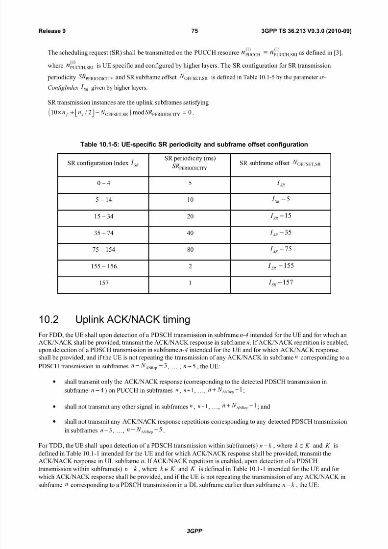
7/29/2019 LTE Procedures 36213-930
http://slidepdf.com/reader/full/lte-procedures-36213-930 75/80
The scheduling request (SR) shall be transmitted on the PUCCH resource)1(
SRIPUCCH,
)1(
PUCCH nn = as defined in [3],
where)1(
SRIPUCCH,n is UE specific and configured by higher layers. The SR configuration for SR transmission
periodicity PERIODICITYSR and SR subframe offset OFFSET,SR N is defined in Table 10.1-5 by the parameter sr-
ConfigIndex SR I given by higher layers.
SR transmission instances are the uplink subframes satisfying
( )OFFSET,SR PERIODICITY10 / 2 mod 0 f sn n N SR× + − = .
Table 10.1-5: UE-specific SR periodicity and subframe offset configuration
SR configuration Index SR I SR periodicity (ms)
PERIODICITYSRSR subframe offset OFFSET,SR N
0 – 4 5 SR I
5 – 14 10 5−SR I
15 – 34 20 15−SR I
35 – 74 40 35−SR I
75 – 154 80 75−SR I
155 – 156 2 155−SR I
157 1 157−SR I
10.2 Uplink ACK/NACK timing
For FDD, the UE shall upon detection of a PDSCH transmission in subframe n-4 intended for the UE and for which an
ACK/NACK shall be provided, transmit the ACK/NACK response in subframe n. If ACK/NACK repetition is enabled,upon detection of a PDSCH transmission in subframe n-4 intended for the UE and for which ACK/NACK response
shall be provided, and if the UE is not repeating the transmission of any ACK/NACK in subframe n corresponding to a
PDSCH transmission in subframes 3ANRep −− N n , … , 5−n , the UE:
• shall transmit only the ACK/NACK response (corresponding to the detected PDSCH transmission insubframe 4−n ) on PUCCH in subframes n , 1+n , …, 1ANRep −+ N n ;
• shall not transmit any other signal in subframes n , 1+n , …, 1ANRep −+ N n ; and
• shall not transmit any ACK/NACK response repetitions corresponding to any detected PDSCH transmission
in subframes 3−n , …, 5ANRep −+ N n .
For TDD, the UE shall upon detection of a PDSCH transmission within subframe(s) k n − , where K k ∈ and K is
defined in Table 10.1-1 intended for the UE and for which ACK/NACK response shall be provided, transmit the
ACK/NACK response in UL subframe n. If ACK/NACK repetition is enabled, upon detection of a PDSCH
transmission within subframe(s) k n − , where K k ∈ and K is defined in Table 10.1-1 intended for the UE and for
which ACK/NACK response shall be provided, and if the UE is not repeating the transmission of any ACK/NACK in
subframe n corresponding to a PDSCH transmission in a DL subframe earlier than subframe k n − , the UE:
3GPP
3GPP TS 36.213 V9.3.0 (2010-09)75Release 9

7/29/2019 LTE Procedures 36213-930
http://slidepdf.com/reader/full/lte-procedures-36213-930 76/80
• shall transmit only the ACK/NACK response (corresponding to the detected PDSCH transmission in
subframe k n − ) on PUCCH in UL subframe n and the next 1ANRep − N UL subframes denoted as 1n , …,
1ANRep − N n ;
• shall not transmit any other signal in UL subframe n , 1n , …, 1ANRep − N n ; and
• shall not transmit any ACK/NACK response repetitions corresponding to any detected PDSCH transmission
in subframes k ni − , where i K k ∈ , i K is the set defined in Table 10.1-1 corresponding to UL subframe in
, and 11 ANRep −≤≤ N i .
For TDD, ACK/NACK bundling, if the UE detects that at least one downlink assignment has been missed as described
in Section 7.3, the UE shall not transmit ACK/NACK in case the UE is not transmitting on PUSCH.
The uplink timing for the ACK corresponding to a detected PDCCH indicating downlink SPS release shall be the sameas the uplink timing for the ACK/NACK corresponding to a detected PDSCH, as defined above.
11 Physical multicast channel related procedures
11.1 UE procedure for receiving the physical multicast channel
The UE shall decode the PMCH when configured by higher layers. The UE may assume that an eNB transmission on
the PMCH is performed according to Section 6.5 of [3].
The MCS I for the PMCH is configured by higher layers. The UE shall use MCS I for the PMCH and Table 7.1.7.1-1 to
determine the modulation order ( mQ ) and TBS index ( TBS I ) used in the PMCH. The UE shall then follow the procedure in Section 7.1.7.2.1 to determine the transport block size, assuming PRB N is equal to
DLRB N .
11.2 UE procedure for receiving MCCH change notification
If a UE is configured by higher layers to decode PDCCHs with the CRC scrambled by the M-RNTI, the UE shall
decode the PDCCH according to the combination defined in table 11.2-1.
Table 11.2-1: PDCCH configured by M-RNTI
DCI format Search Space
DCI format 1C Common
The 8-bit information for MCCH change notification [11], as signalled on the PDCCH, shall be delivered to higher
layers.
3GPP
3GPP TS 36.213 V9.3.0 (2010-09)76Release 9

7/29/2019 LTE Procedures 36213-930
http://slidepdf.com/reader/full/lte-procedures-36213-930 77/80
Annex A (informative):
Change historyChange history
Date TSG # TSG Doc. CR Rev Subject/Comment Old New
2006-09 Draft version created 0.0.0
2006-10 Endorsed by RAN1 0.0.0 0.1.0
2007-01 Inclusion of decisions from RAN1#46bis and RAN1#47 0.1.0 0.1.1
2007-01 Endorsed by RAN1 0.1.1 0.2.0
2007-02 Inclusion of decisions from RAN1#47bis 0.2.0 0.2.1
2007-02 Endorsed by RAN1 0.2.1 0.3.0
2007-02 Editor’s version including decisions from RAN1#48 & RAN1#47bis 0.3.0 0.3.1
2007-03 Updated Editor’s version 0.3.1 0.3.2
2007-03 RAN#35 RP-070171 For information at RAN#35 0.3.2 1.0.0
2007-03 Random access text modified to better reflect RAN1 scope 1.0.0 1.0.1
2007-03 Updated Editor’s version 1.0.1 1.0.2
2007-03 Endorsed by RAN1 1.0.2 1.1.0
2007-05 Updated Editor’s version 1.1.0 1.1.12007-05 Updated Editor’s version 1.1.1 1.1.2
2007-05 Endorsed by RAN1 1.1.2 1.2.0
2007-08 Updated Editor’s version 1.2.0 1.2.1
2007-08 Updated Editor’s version – uplink power control from RAN1#49bis 1.2.1 1.2.2
2007-08 Endorsed by RAN1 1.2.2 1.3.0
2007-09 Updated Editor’s version reflecting RAN#50 decisions 1.3.0 1.3.1
2007-09 Updated Editor’s version reflecting comments 1.3.1 1.3.2
2007-09 Updated Editor’s version reflecting further comments 1.3.2 1.3.3
2007-09 Updated Editor’s version reflecting further comments 1.3.3 1.3.4
2007-09 Updated Edtior’s version reflecting further comments 1.3.4 1.3.5
2007-09 RAN#37 RP-070731 Endorsed by RAN1 1.3.5 2.0.0
2007-09 RAN#37 RP-070737 For approval at RAN#37 2.0.0 2.1.0
12/09/07 RAN_37 RP-070737 - - Approved version 2.1.0 8.0.0
28/11/07 RAN_38 RP-070949 0001 2 Update of 36.213 8.0.0 8.1.0
05/03/08 RAN_39 RP-080145 0002 - Update of TS36.213 according to changes listed in cover sheet 8.1.0 8.2.028/05/08 RAN_40 RP-080434 0003 1 PUCCH timing and other formatting and typo corrections 8.2.0 8.3.0
28/05/08 RAN_40 RP-080434 0006 1 PUCCH power control for non-unicast information 8.2.0 8.3.0
28/05/08 RAN_40 RP-080434 0008 - UE ACK/NACK Procedure 8.2.0 8.3.0
28/05/08 RAN_40 RP-080434 0009 - UL ACK/NACK timing for TDD 8.2.0 8.3.0
28/05/08 RAN_40 RP-080434 0010 - Specification of UL control channel assignment 8.2.0 8.3.0
28/05/08 RAN_40 RP-080434 0011 - Precoding Matrix for 2Tx Open-loop SM 8.2.0 8.3.0
28/05/08 RAN_40 RP-080434 0012 - Clarifications on UE selected CQI reports 8.2.0 8.3.0
28/05/08 RAN_40 RP-080434 0013 1 UL HARQ Operation and Timing 8.2.0 8.3.0
28/05/08 RAN_40 RP-080434 0014 - SRS power control 8.2.0 8.3.0
28/05/08 RAN_40 RP-080434 0015 1 Correction of UE PUSCH frequency hopping procedure 8.2.0 8.3.0
28/05/08 RAN_40 RP-080434 0017 4 Blind PDCCH decoding 8.2.0 8.3.0
28/05/08 RAN_40 RP-080434 0019 1 Tx Mode vs DCI format is clarified 8.2.0 8.3.0
28/05/08 RAN_40 RP-080434 0020 - Resource allocation for distributed VRB 8.2.0 8.3.0
28/05/08 RAN_40 RP-080434 0021 2 Power Headroom 8.2.0 8.3.0
28/05/08 RAN_40 RP-080434 0022 - Clarification for RI reporting in PUCCH and PUSCH reportingmodes 8.2.0 8.3.0
28/05/08 RAN_40 RP-080434 0025 - Correction of the description of PUSCH power control for TDD 8.2.0 8.3.0
28/05/08 RAN_40 RP-080434 0026 - UL ACK/NACK procedure for TDD 8.2.0 8.3.0
28/05/08 RAN_40 RP-080434 0027 - Indication of radio problem detection 8.2.0 8.3.0
28/05/08 RAN_40 RP-080434 0028 - Definition of Relative Narrowband TX Power Indicator 8.2.0 8.3.0
28/05/08 RAN_40 RP-080434 0029 - Calculation of ΔTF(i ) for UL-PC 8.2.0 8.3.0
28/05/08 RAN_40 RP-080434 0030 - CQI reference and set S definition, CQI mode removal, andMiscellanious
8.2.0 8.3.0
28/05/08 RAN_40 RP-080434 0031 - Modulation order and TBS determination for PDSCH and PUSCH 8.2.0 8.3.0
28/05/08 RAN_40 RP-080434 0032 - On Sounding RS 8.2.0 8.3.0
28/05/08 RAN_40 RP-080426 0033 - Multiplexing of rank and CQI/PMI reports on PUCCH 8.2.0 8.3.0
28/05/08 RAN_40 RP-080466 0034 - Timing advance command responding time 8.2.0 8.3.0
09/09/08 RAN_41 RP-080670 37 2 SRS hopping pattern for closed loop antenna selection 8.3.0 8.4.0
09/09/08 RAN_41 RP-080670 39 2 Clarification on uplink power control 8.3.0 8.4.0
09/09/08 RAN_41 RP-080670 41 - Clarification on DCI formats using resource allocation type 2 8.3.0 8.4.0
09/09/08 RAN_41 RP-080670 43 2 Clarification on tree structure of CCE aggregations 8.3.0 8.4.009/09/08 RAN_41 RP-080670 46 2 Correction of the description of PUCCH power control for TDD 8.3.0 8.4.0
09/09/08 RAN_41 RP-080670 47 1 Removal of CR0009 8.3.0 8.4.0
09/09/08 RAN_41 RP-080670 48 1 Correction of mapping of cyclic shift value to PHICH modifier 8.3.0 8.4.0
3GPP
3GPP TS 36.213 V9.3.0 (2010-09)77Release 9

7/29/2019 LTE Procedures 36213-930
http://slidepdf.com/reader/full/lte-procedures-36213-930 78/80
Change historyDate TSG # TSG Doc. CR Rev Subject/Comment Old New
09/09/08 RAN_41 RP-080670 49 - TBS disabling for DCI formats 2 and 2A 8.3.0 8.4.0
09/09/08 RAN_41 RP-080670 50 - Correction of maximum TBS sizes 8.3.0 8.4.0
09/09/08 RAN_41 RP-08067051 -
Completion of the table specifying the number of bits for theperiodic feedback
8.3.0 8.4.0
09/09/08 RAN_41 RP-08067054 -
Clarification of RNTI for PUSCH/PUCCH power control with DCIformats 3/3A
8.3.0 8.4.0
09/09/08 RAN_41 RP-080670 55 1 Clarification on mapping of Differential CQI fields 8.3.0 8.4.0
09/09/08 RAN_41 RP-080670 59 1 PUSCH Power Control 8.3.0 8.4.0
09/09/08 RAN_41 RP-08067060 -
RB restriction and modulation order for CQI-only transmission onPUSCH
8.3.0 8.4.0
09/09/08 RAN_41 RP-080670 61 - Modulation order determination for uplink retransmissions 8.3.0 8.4.0
09/09/08 RAN_41 RP-080670 62 2 Introducing missing L1 parameters into 36.213 8.3.0 8.4.0
09/09/08 RAN_41 RP-080670 63 2 Correcting the range and representation of delta_TF_PUCCH 8.3.0 8.4.0
09/09/08 RAN_41 RP-080670 64 1 Adjusting TBS sizes to for VoIP 8.3.0 8.4.0
09/09/08 RAN_41 RP-080670 67 - Correction to the downlink resource allocation 8.3.0 8.4.0
09/09/08 RAN_41 RP-080670 68 - Removal of special handling for PUSCH mapping in PUCCH region 8.3.0 8.4.0
09/09/08 RAN_41 RP-080670 69 - Correction to the formulas for uplink power control 8.3.0 8.4.0
09/09/08 RAN_41 RP-080670 70 1 Definition of Bit Mapping for DCI Signalling 8.3.0 8.4.0
09/09/08 RAN_41 RP-080670 71 - Clarification on PUSCH TPC commands 8.3.0 8.4.0
09/09/08 RAN_41 RP-080670 72 1 Reference for CQI/PMI Reporting Offset 8.3.0 8.4.0
09/09/08 RAN_41 RP-080670 74 - Correction to the downlink/uplink timing 8.3.0 8.4.0
09/09/08 RAN_41 RP-080670 75 - Correction to the time alignment command 8.3.0 8.4.009/09/08 RAN_41 RP-080670 77 1 Correction of offset signal ling of UL Control information MCS 8.3.0 8.4.0
09/09/08 RAN_41 RP-080670 78 2 DCI format1C 8.3.0 8.4.0
09/09/08 RAN_41 RP-080670 80 - Correction to Precoder Cycl ing for Open-loop Spatial Multiplexing 8.3.0 8.4.0
09/09/08 RAN_41 RP-080670 81 1 Clarifying Periodic CQI Reporting using PUCCH 8.3.0 8.4.0
09/09/08 RAN_41 RP-080670 84 1 CQI reference measurement period 8.3.0 8.4.0
09/09/08 RAN_41 RP-080670 86 - Correction on downlink multi-user MIMO 8.3.0 8.4.0
09/09/08 RAN_41 RP-080670 87 - PUCCH Reporting 8.3.0 8.4.0
09/09/08 RAN_41 RP-080670 88 1 Handling of Uplink Grant in Random Access Response 8.3.0 8.4.0
09/09/08 RAN_41 RP-080670 89 - Correction to UL Hopping operation 8.3.0 8.4.0
09/09/08 RAN_41 RP-080670 90 - DRS EPRE 8.3.0 8.4.0
09/09/08 RAN_41 RP-080670 92 - Uplink ACK/NACK mapping for TDD 8.3.0 8.4.0
09/09/08 RAN_41 RP-080670 93 - UL SRI Parameters Configuration 8.3.0 8.4.0
09/09/08 RAN_41 RP-080670 94 - Miscellaneous updates for 36.213 8.3.0 8.4.0
09/09/08 RAN_41 RP-080670 95 - Clarifying Requirement for Max PDSCH Coding Rate 8.3.0 8.4.0
09/09/08 RAN_41 RP-080670 96 - UE Specific SRS Configuration 8.3.0 8.4.009/09/08 RAN_41 RP-080670 97 - DCI Format 1A changes needed for scheduling Broadcast Control 8.3.0 8.4.0
09/09/08 RAN_41 RP-080670 98 - Processing of TPC bits in the random access response 8.3.0 8.4.0
09/09/08 RAN_41 RP-080670 100 1 Support of multi-bit ACK/NAK transmission in TDD 8.3.0 8.4.0
03/12/08 RAN_42 RP-081075 82 3 Corrections to RI for CQI reporting 8.4.0 8.5.0
03/12/08 RAN_42 RP-081075 83 2 Moving description of large delay CDD to 36.211 8.4.0 8.5.0
03/12/08 RAN_42 RP-081075 102 3 Reception of DCI formats 8.4.0 8.5.0
03/12/08 RAN_42 RP-081075 105 8 Alignment of RAN1/RAN2 specification 8.4.0 8.5.0
03/12/08 RAN_42 RP-081075107 1
General correction of reset of power control and random accessresponse message
8.4.0 8.5.0
03/12/08 RAN_42 RP-081075 108 2 Final details on codebook subset restrictions 8.4.0 8.5.0
03/12/08 RAN_42 RP-081075 109 - Correction on the definition of Pmax 8.4.0 8.5.0
03/12/08 RAN_42 RP-081075 112 2 CQI/PMI reference measurement periods 8.4.0 8.5.0
03/12/08 RAN_42 RP-081075 113 - Correction of introduction of shortened SR 8.4.0 8.5.0
03/12/08 RAN_42 RP-081075 114 - RAN1/2 specification alignment on HARQ operation 8.4.0 8.5.0
03/12/08 RAN_42 RP-081075 115 - Introducing other missing L1 parameters in 36.213 8.4.0 8.5.0
03/12/08 RAN_42 RP-081075 116 - PDCCH blind decoding 8.4.0 8.5.0
03/12/08 RAN_42 RP-081075 117 - PDCCH search space 8.4.0 8.5.0
03/12/08 RAN_42 RP-081075 119 - Delta_TF for PUSCH 8.4.0 8.5.0
03/12/08 RAN_42 RP-081075120 -
Delta_preamble_msg3 parameter values and TPC command in RAresponse
8.4.0 8.5.0
03/12/08 RAN_42 RP-081075 122 1 Correction of offset signaling of uplink control information MCS 8.4.0 8.5.0
03/12/08 RAN_42 RP-081075 124 - Miscellaneous Corrections 8.4.0 8.5.0
03/12/08 RAN_42 RP-081075 125 - Clarification of the uplink index in TDD mode 8.4.0 8.5.0
03/12/08 RAN_42 RP-081075 126 - Clarification of the uplink transmission configurations 8.4.0 8.5.0
03/12/08 RAN_42 RP-081075 127 2 Correction to the PHICH index assignment 8.4.0 8.5.0
03/12/08 RAN_42 RP-081075 128 - Clarification of type-2 PDSCH resource allocation for format 1C 8.4.0 8.5.0
03/12/08 RAN_42 RP-081075 129 - Clarification of uplink grant in random access response 8.4.0 8.5.0
03/12/08 RAN_42 RP-081075 130 - UE sounding procedure 8.4.0 8.5.0
03/12/08 RAN_42 RP-081075134 -
Change for determining DCI format 1A TBS table column indicator for broadcast control
8.4.0 8.5.0
03/12/08 RAN_42 RP-081075 135 - Clarifying UL VRB Allocation 8.4.0 8.5.003/12/08 RAN_42 RP-081075 136 1 Correction for Aperiodic CQI 8.4.0 8.5.0
03/12/08 RAN_42 RP-081075 137 1 Correction for Aperiodic CQI Reporting 8.4.0 8.5.0
03/12/08 RAN_42 RP-081075 138 1 Correction to PUCCH CQI reporting mode for N^DL_RB <= 7 8.4.0 8.5.0
3GPP
3GPP TS 36.213 V9.3.0 (2010-09)78Release 9

7/29/2019 LTE Procedures 36213-930
http://slidepdf.com/reader/full/lte-procedures-36213-930 79/80
Change historyDate TSG # TSG Doc. CR Rev Subject/Comment Old New
03/12/08 RAN_42 RP-081075 140 1 On sounding procedure in TDD 8.4.0 8.5.0
03/12/08 RAN_42 RP-081075 141 1 Alignment of RAN1/RAN3 specification 8.4.0 8.5.0
03/12/08 RAN_42 RP-081075 143 1 TTI bundling 8.4.0 8.5.0
03/12/08 RAN_42 RP-081075 144 1 ACK/NACK transmission on PUSCH for LTE TDD 8.4.0 8.5.0
03/12/08 RAN_42 RP-081075 145 1 Timing relationship between PHICH and its associated PUSCH 8.4.0 8.5.0
03/12/08 RAN_42 RP-081075 147 1 Definition of parameter for downlink reference signal transmitpower 8.4.0 8.5.0
03/12/08 RAN_42 RP-081075 148 1 Radio link monitoring 8.4.0 8.5.0
03/12/08 RAN_42 RP-081075 149 1 Correction in 36.213 related to TDD downlink HARQ processes 8.4.0 8.5.0
03/12/08 RAN_42 RP-081075 151 - Nominal PDSCH-to-RS EPRE Offset for CQI Reporting 8.4.0 8.5.0
03/12/08 RAN_42 RP-081075 152 1 Support of UL ACK/NAK repetition in Rel-8 8.4.0 8.5.0
03/12/08 RAN_42 RP-081075 155 - Clarification of misconfiguration of aperiodic CQI and SR 8.4.0 8.5.0
03/12/08 RAN_42 RP-081075156 1
Correction of control information multiplexing in subframe bundlingmode
8.4.0 8.5.0
03/12/08 RAN_42 RP-081075 157 - Correction to the PHICH index assignment 8.4.0 8.5.0
03/12/08 RAN_42 RP-081075 158 1 UE transmit antenna selection 8.4.0 8.5.0
03/12/08 RAN_42 RP-081075 159 - Clarification of spatial different CQI for CQI reporting Mode 2-1 8.4.0 8.5.0
03/12/08 RAN_42 RP-081075 160 1 Corrections for TDD ACK/NACK bundling and multiplexing 8.4.0 8.5.0
03/12/08 RAN_42 RP-081075 161 - Correction to RI for Open-Loop Spatial Multiplexing 8.4.0 8.5.0
03/12/08 RAN_42 RP-081075 162 - Correction of differential CQI 8.4.0 8.5.0
03/12/08 RAN_42 RP-081075 163 - Inconsistency between PMI definition and codebook index 8.4.0 8.5.0
03/12/08 RAN_42 RP-081075 164 - PDCCH validation for semi-persistent scheduling 8.4.0 8.5.003/12/08 RAN_42 RP-081075
165 1Correction to the UE behavior of PUCCH CQI piggybacked onPUSCH
8.4.0 8.5.0
03/12/08 RAN_42 RP-081075166 -
Correction on SRS procedure when shortened PUCCH format isused
8.4.0 8.5.0
03/12/08 RAN_42 RP-081075167 1
Transmission overlapping of physical channels/signals with PDSCHfor transmission mode 7
8.4.0 8.5.0
03/12/08 RAN_42 RP-081075 169 - Clarification of SRS and SR transmission 8.4.0 8.5.0
03/12/08 RAN_42 RP-081075 171 - Clarification on UE behavior when skipping decoding 8.4.0 8.5.0
03/12/08 RAN_42 RP-081075 172 1 PUSCH Hopping operation corrections 8.4.0 8.5.0
03/12/08 RAN_42 RP-081075 173 - Clarification on message 3 transmission timing 8.4.0 8.5.0
03/12/08 RAN_42 RP-081075 174 - MCS handling for DwPTS 8.4.0 8.5.0
03/12/08 RAN_42 RP-081075175 -
Clarification of UE-specific time domain position for SRtransmission
8.4.0 8.5.0
03/12/08 RAN_42 RP-081075 176 1 Physical layer parameters for CQI reporting 8.4.0 8.5.0
03/12/08 RAN_42 RP-081075 177 - A-periodic CQI clarification for TDD UL/DL configuration 0 8.4.0 8.5.003/12/08 RAN_42 RP-081075179 1
Correction to the definitions of rho_A and rho_B (downlink power allocation)
8.4.0 8.5.0
03/12/08 RAN_42 RP-081075 180 - Clarification of uplink A/N resource indication 8.4.0 8.5.0
03/12/08 RAN_42 RP-081075181 -
PDCCH format 0 for message 3 adaptive retransmission andtransmission of control information in message 3 during contentionbased random access procedure
8.4.0 8.5.0
03/12/08 RAN_42 RP-081075182 -
To Fix the Discrepancy of Uplink Power Control and ChannelCoding of Control Information in PUSCH
8.4.0 8.5.0
03/12/08 RAN_42 RP-081122 183 1 CQI reporting for antenna port 5 8.4.0 8.5.0
03/12/08 RAN_42 RP-081110 168 1 Clarification on path loss definition 8.4.0 8.5.0
04/03/09 RAN_43 RP-090236 184 1 Corrections to Transmitted Rank Indication 8.5.0 8.6.0
04/03/09 RAN_43 RP-090236 185 4 Corrections to transmission modes 8.5.0 8.6.0
04/03/09 RAN_43 RP-090236 186 2 Delta_TF configuration for control only PUSCH 8.5.0 8.6.0
04/03/09 RAN_43 RP-090236 187 1 Correction to concurrent SRS and ACK/NACK transmission 8.5.0 8.6.0
04/03/09 RAN_43 RP-090236 191 1 PDCCH release for semi-persistent scheduling 8.5.0 8.6.0
04/03/09 RAN_43 RP-090236 192 1 Correction on ACKNACK transmission on PUSCH for LTE TDD 8.5.0 8.6.004/03/09 RAN_43
RP-090236193 - Correction to subband differential CQI value to offset level mapping
for aperiodic CQI reporting8.5.0 8.6.0
04/03/09 RAN_43 RP-090236 194 - Correction for DRS Collision handling 8.5.0 8.6.0
04/03/09 RAN_43RP-090236
196 2 Alignment of RAN1/RAN4 specification on UE maximum outputpower
8.5.0 8.6.0
04/03/09 RAN_43 RP-090236 197 - Transmission scheme for transmission mode 7 with SPS C-RNTI 8.5.0 8.6.0
04/03/09 RAN_43RP-090236
198 - Clarifying bandwidth parts for periodic CQI reporting and CQIrefererence period
8.5.0 8.6.0
04/03/09 RAN_43RP-090236
199 2 Correction to the ACK/NACK bundling in case of transmissionmode 3 and 4
8.5.0 8.6.0
04/03/09 RAN_43 RP-090236 200 - ACK/NAK repetition for TDD ACK/NAK multiplexing 8.5.0 8.6.0
04/03/09 RAN_43 RP-090236 201 - Clarifying UL ACK/NAK transmission in TDD 8.5.0 8.6.0
04/03/09 RAN_43 RP-090236 202 - Corrections to UE Transmit Antenna Selection 8.5.0 8.6.0
04/03/09 RAN_43 RP-090236 203 - Correction to UE PUSCH hopping procedure 8.5.0 8.6.0
04/03/09 RAN_43 RP-090236 204 - Correction to PHICH resource association in TTI bundling 8.5.0 8.6.004/03/09 RAN_43 RP-090236 205 - Clarification of the length of resource assignment 8.5.0 8.6.0
04/03/09 RAN_43RP-090236
206 - Correction on ACK/NACK transmission for downlink SPS resourcerelease
8.5.0 8.6.0
04/03/09 RAN_43 RP-090236 207 - Introduction of addit ional values of wideband CQI/PMI periodicities 8.5.0 8.6.0
3GPP
3GPP TS 36.213 V9.3.0 (2010-09)79Release 9

7/29/2019 LTE Procedures 36213-930
http://slidepdf.com/reader/full/lte-procedures-36213-930 80/80
Change historyDate TSG # TSG Doc. CR Rev Subject/Comment Old New
04/03/09 RAN_43 RP-090236 208 2 Correction to CQI/PMI/RI reporting field 8.5.0 8.6.0
04/03/09 RAN_43 RP-090236 209 2 Correction to rho_A definition for CQI calculation 8.5.0 8.6.0
04/03/09 RAN_43 RP-090236 210 - Correction to erroneous cases in PUSCH linear block codes 8.5.0 8.6.0
04/03/09 RAN_43 RP-090236 211 1 Removing RL monitoring start and stop 8.5.0 8.6.0
04/03/09 RAN_43 RP-090236 214 1 Correction to type-1 and type-2 PUSCH hopping 8.5.0 8.6.0
04/03/09 RAN_43 RP-090236 215 - Contradicting statements on determination of CQI subband size 8.5.0 8.6.004/03/09 RAN_43 RP-090236 216 - Corrections to SRS 8.5.0 8.6.0
04/03/09 RAN_43 RP-090236 219 2 Miscellaneous corrections on TDD ACKNACK 8.5.0 8.6.0
04/03/09 RAN_43 RP-090236 221 1 CR for Redundancy Version mapping function for DCI 1C 8.5.0 8.6.0
04/03/09 RAN_43RP-090236
223 - Scrambling of PUSCH corresponding to Random AccessResponse Grant
8.5.0 8.6.0
04/03/09 RAN_43 RP-090236 225 - Removal of SRS with message 3 8.5.0 8.6.0
04/03/09 RAN_43 RP-090236 226 3 PRACH retransmission timing 8.5.0 8.6.0
04/03/09 RAN_43 RP-090236 227 - Clarifying error handling of PDSCH and PUSCH assignments 8.5.0 8.6.0
04/03/09 RAN_43 RP-090236 228 - Clarify PHICH index mapping 8.5.0 8.6.0
04/03/09 RAN_43 RP-090236 229 - Correction of CQI timing 8.5.0 8.6.0
04/03/09 RAN_43 RP-090236 230 - Alignment of CQI parameter names with RRC 8.5.0 8.6.0
04/03/09 RAN_43 RP-090236 231 1 Removal of ‘Off’ values for periodic reporting in L1 8.5.0 8.6.0
04/03/09 RAN_43 RP-090236 232 - Default value of RI 8.5.0 8.6.0
04/03/09 RAN_43 RP-090236 233 1 Clarification of uplink timing adjustments 8.5.0 8.6.0
04/03/09 RAN_43 RP-090236 234 - Clarification on ACK/NAK repetition 8.5.0 8.6.0
27/05/09 RAN_44RP-090529
235 1 Correction to the condition of resetting accumulated uplink power correction
8.6.0 8.7.0
27/05/09 RAN_44RP-090529
236 - Correction to the random access channel parameters received fromhigher layer
8.6.0 8.7.0
27/05/09 RAN_44 RP-090529 237 - Correction on TDD ACKNACK 8.6.0 8.7.0
27/05/09 RAN_44 RP-090529 238 1 Correction on CQI reporting 8.6.0 8.7.0
27/05/09 RAN_44 RP-090529 239 - Correction on the HARQ process number 8.6.0 8.7.0
27/05/09 RAN_44 RP-090529 241 1 CR correction of the description on TTI-bundling 8.6.0 8.7.0
27/05/09 RAN_44RP-090529
242 1 Clarify latest and initial PDCCH for PDSCH and PUSCHtransmisisons, and NDI for SPS activation
8.6.0 8.7.0
27/05/09 RAN_44 RP-090529 243 - Clarify DRS EPRE 8.6.0 8.7.0
27/05/09 RAN_44 RP-090529 244 1 Clarification on TPC commands for SPS 8.6.0 8.7.0
15/09/09 RAN_45 RP-090888 245 1 Correction to PUSCH hopping and PHICH mapping procedures 8.7.0 8.8.0
15/09/09 RAN_45 RP-090888 246 - Clarification on subband indexing in periodic CQI reporting 8.7.0 8.8.0
15/09/09 RAN_45 RP-090888 247 2 Correction to DVRB operation in TDD transmission mode 7 8.7.0 8.8.0
15/09/09 RAN_45 RP-090888 249 - Clarification of concurrent ACKNACK and periodic PMI/RItransmission on PUCCH for TDD
8.7.0 8.8.0
15/09/09 RAN_45 RP-090888 250 - Clarify Inter-cell synchronization text 8.7.0 8.8.0
01/12/09 RAN_46 RP-091172 248 1 Introduction of LTE positioning 8.8.0 9.0.0
01/12/09 RAN_46 RP-091172 254 - Clar ification of PDSCH and PRS in combination for LTE positioning 8.8.0 9.0.0
01/12/09 RAN_46 RP-091177 255 5 Editorial corrections to 36.213 8.8.0 9.0.0
01/12/09 RAN_46 RP-091257 256 1 Introduction of enhanced dual layer transmission 8.8.0 9.0.0
01/12/09 RAN_46 RP-091177 257 1 Add shorter SR periodicity 8.8.0 9.0.0
01/12/09 RAN_46 RP-091256 258 - Introduction of LTE MBMS 8.8.0 9.0.0
17/12/09 RAN_46RP-091257
256 1 Correction by MCC due to wrong implementation of CR0256r1 –Sentence is added to Single-antenna port scheme section 7.1.1
9.0.0 9.0.1
16/03/10 RAN_47RP-100211
259 3 UE behavior when collision of antenna port 7/8 with PBCH or SCHhappened and when distributed VRB is used with antenna port 7
9.0.1 9.1.0
16/03/10 RAN_47 RP-100210 260 1 MCCH change notification using DCI format 1C 9.0.1 9.1.0
16/03/10 RAN_47RP-100211
263 - Correction on PDSCH EPRE and UE-specific RS EPRE for Rel-9enhanced DL transmissions
9.0.1 9.1.0
01/06/10 RAN_48RP-100589
265 - Clarification for TDD when multiplexing ACK/NACK with SR of ACK/NACK with CQI/PMI or RI
9.1.0 9.2.0
01/06/10 RAN_48 RP-100590 268 1 Clarification of PRS EPRE 9.1.0 9.2.0
14/09/10 RAN_49 RP-100900 269 - Clarification on Extended CP support with Transmission Mode 8 9.2.0 9.3.0
3GPP TS 36.213 V9.3.0 (2010-09)80Release 9