LTE Permulaan
48
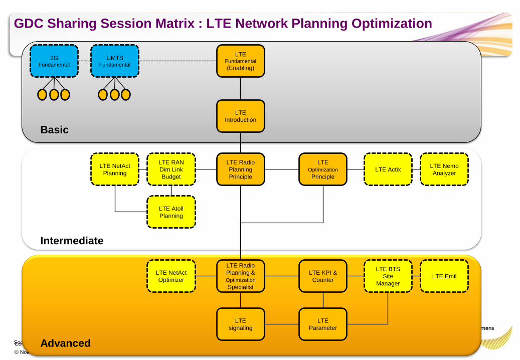
Confidential © Nokia Siemens Networks Soc Classification level GDC Sharing Session Matrix : LTE Network Planning Optimization LTE Fundamental (Enabling) LTE Radio Planning Principle LTE Optimization Principle LTE Introduction LTE Radio Planning & Optimization Specialist LTE KPI & Counter LTE RAN Dim Link Budget LTE NetAct Planning LTE Actix LTE Nemo Analyzer LTE BTS Site Manager LTE Atoll Planning LTE Emil UMTS Fundamental 2G Fundamental LTE Parameter Basic Intermediate Advanced LTE NetAct Optimizer LTE signaling
-
Upload
indra-aminudin -
Category
Documents
-
view
44 -
download
3
description
Introduction of LTE
Transcript of LTE Permulaan
Confidential
© Nokia Siemens Networks
Soc Classification level
GDC Sharing Session Matrix : LTE Network Planning Optimization
LTE Fundamental
(Enabling)
LTE Radio
Planning
Principle
LTE
Optimization
Principle
LTE
Introduction
LTE Radio
Planning &
Optimization
Specialist
LTE KPI &
Counter
LTE RAN
Dim Link
Budget
LTE NetAct
Planning LTE Actix
LTE Nemo
Analyzer
LTE BTS
Site
Manager
LTE Atoll
Planning
LTE Emil
UMTS Fundamental
2G Fundamental
LTE
Parameter
Basic
Intermediate
Advanced
LTE NetAct
Optimizer
LTE
signaling

Confidential
© Nokia Siemens Networks
Soc Classification level
LTE Introduction
Confidential
© Nokia Siemens Networks
Summary
•LTE Overview
•LTE Network Architecture
•LTE Air Interface - DL Air Interface
• - UL Air Interface
• - Physical Layer
•LTE Connection Management
•LTE Mobility Management
Confidential
© Nokia Siemens Networks
LTE Overview
Presentation / Author / Date
Confidential
© Nokia Siemens Networks
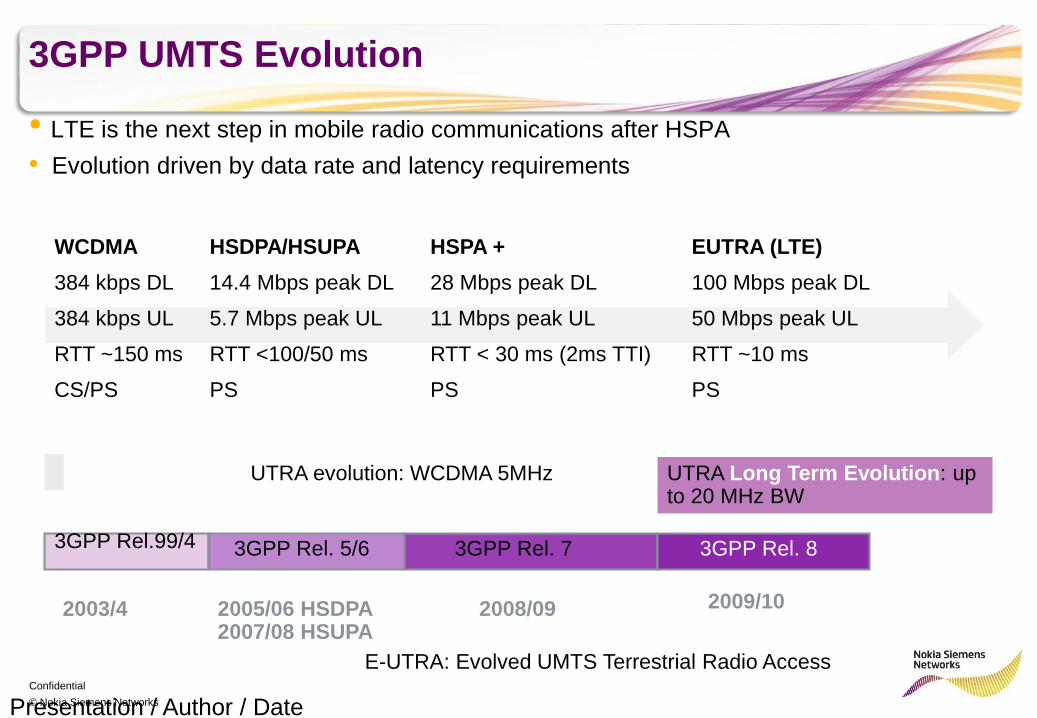
3GPP UMTS Evolution
• LTE is the next step in mobile radio communications after HSPA
• Evolution driven by data rate and latency requirements
Presentation / Author / Date
WCDMA
384 kbps DL
384 kbps UL
RTT ~150 ms
CS/PS
HSDPA/HSUPA
14.4 Mbps peak DL
5.7 Mbps peak UL
RTT <100/50 ms
PS
HSPA +
28 Mbps peak DL
11 Mbps peak UL
RTT < 30 ms (2ms TTI)
PS
EUTRA (LTE)
100 Mbps peak DL
50 Mbps peak UL
RTT ~10 ms
PS
3GPP Rel.99/4 3GPP Rel. 5/6 3GPP Rel. 7 3GPP Rel. 8
2003/4 2005/06 HSDPA 2007/08 HSUPA
2008/09 2009/10
UTRA evolution: WCDMA 5MHz UTRA Long Term Evolution: up to 20 MHz BW
E-UTRA: Evolved UMTS Terrestrial Radio Access
Confidential
© Nokia Siemens Networks
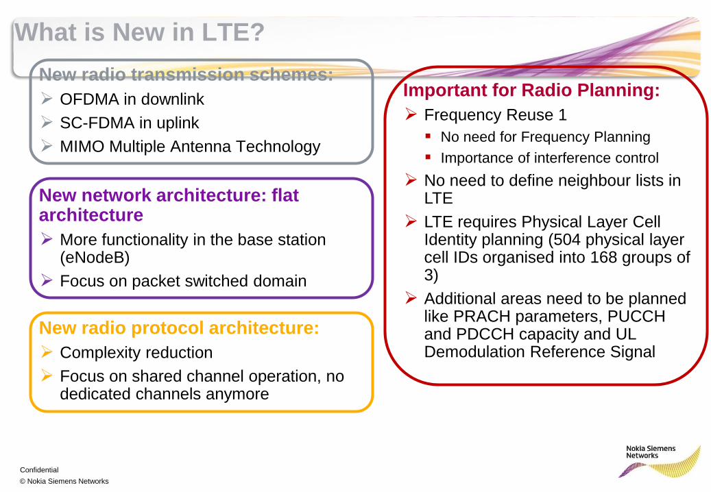
What is New in LTE?
New radio transmission schemes:
OFDMA in downlink
SC-FDMA in uplink
MIMO Multiple Antenna Technology
New network architecture: flat architecture
More functionality in the base station (eNodeB)
Focus on packet switched domain
New radio protocol architecture:
Complexity reduction
Focus on shared channel operation, no dedicated channels anymore
Important for Radio Planning:
Frequency Reuse 1
No need for Frequency Planning
Importance of interference control
No need to define neighbour lists in LTE
LTE requires Physical Layer Cell Identity planning (504 physical layer cell IDs organised into 168 groups of 3)
Additional areas need to be planned like PRACH parameters, PUCCH and PDCCH capacity and UL Demodulation Reference Signal
Confidential
© Nokia Siemens Networks
LTE Architecture Network Elements and Interfaces
Presentation / Author / Date
Confidential
© Nokia Siemens Networks
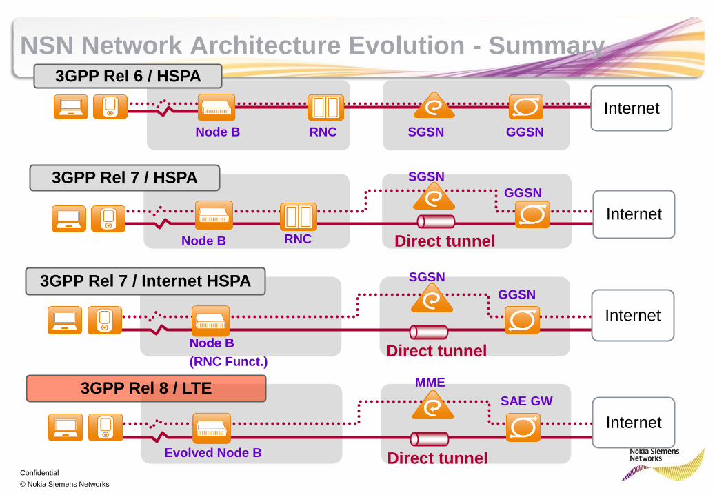
NSN Network Architecture Evolution - Summary
Node B RNC SGSN GGSN
Internet
3GPP Rel 6 / HSPA
Direct tunnel
3GPP Rel 7 / HSPA
Internet
Node B RNC
SGSN
GGSN
Direct tunnel
3GPP Rel 7 / Internet HSPA
Internet
Node B
SGSN
GGSN
Node B
(RNC Funct.)
Direct tunnel
3GPP Rel 8 / LTE
Internet
Evolved Node B
MME
SAE GW
Confidential
© Nokia Siemens Networks
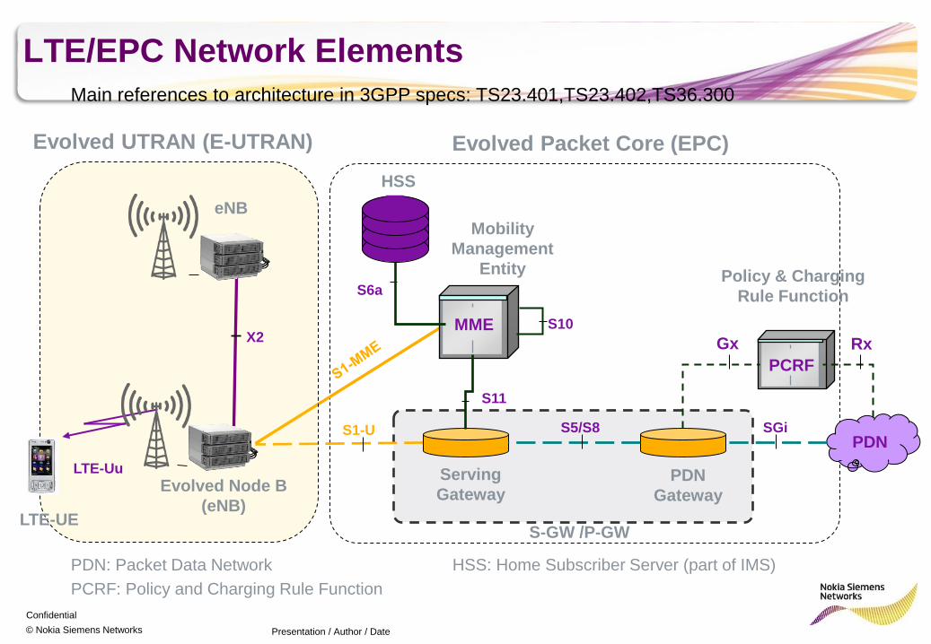
LTE/EPC Network Elements
Presentation / Author / Date
Main references to architecture in 3GPP specs: TS23.401,TS23.402,TS36.300
Evolved UTRAN (E-UTRAN)
MME S10
S6a
Serving
Gateway
S1-U
S11
PDN
Gateway
PDN
Evolved Packet Core (EPC)
PCRF
Gx Rx
SGi S5/S8
HSS
Mobility
Management
Entity Policy & Charging
Rule Function
S-GW /P-GW LTE-UE
Evolved Node B
(eNB)
X2
LTE-Uu
eNB
PDN: Packet Data Network
PCRF: Policy and Charging Rule Function
HSS: Home Subscriber Server (part of IMS)
Confidential
© Nokia Siemens Networks
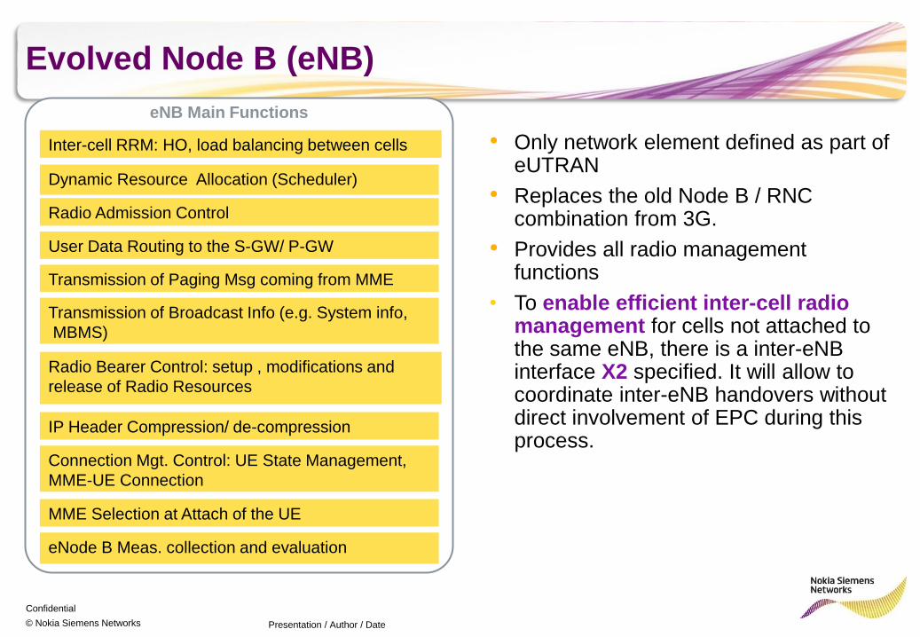
Evolved Node B (eNB)
Presentation / Author / Date
Inter-cell RRM: HO, load balancing between cells
Radio Bearer Control: setup , modifications and
release of Radio Resources
Connection Mgt. Control: UE State Management,
MME-UE Connection
Radio Admission Control
eNode B Meas. collection and evaluation
Dynamic Resource Allocation (Scheduler)
eNB Main Functions
IP Header Compression/ de-compression
MME Selection at Attach of the UE
User Data Routing to the S-GW/ P-GW
Transmission of Paging Msg coming from MME
Transmission of Broadcast Info (e.g. System info,
MBMS)
• Only network element defined as part of eUTRAN
• Replaces the old Node B / RNC combination from 3G.
• Provides all radio management functions
• To enable efficient inter-cell radio management for cells not attached to the same eNB, there is a inter-eNB interface X2 specified. It will allow to coordinate inter-eNB handovers without direct involvement of EPC during this process.
Confidential
© Nokia Siemens Networks
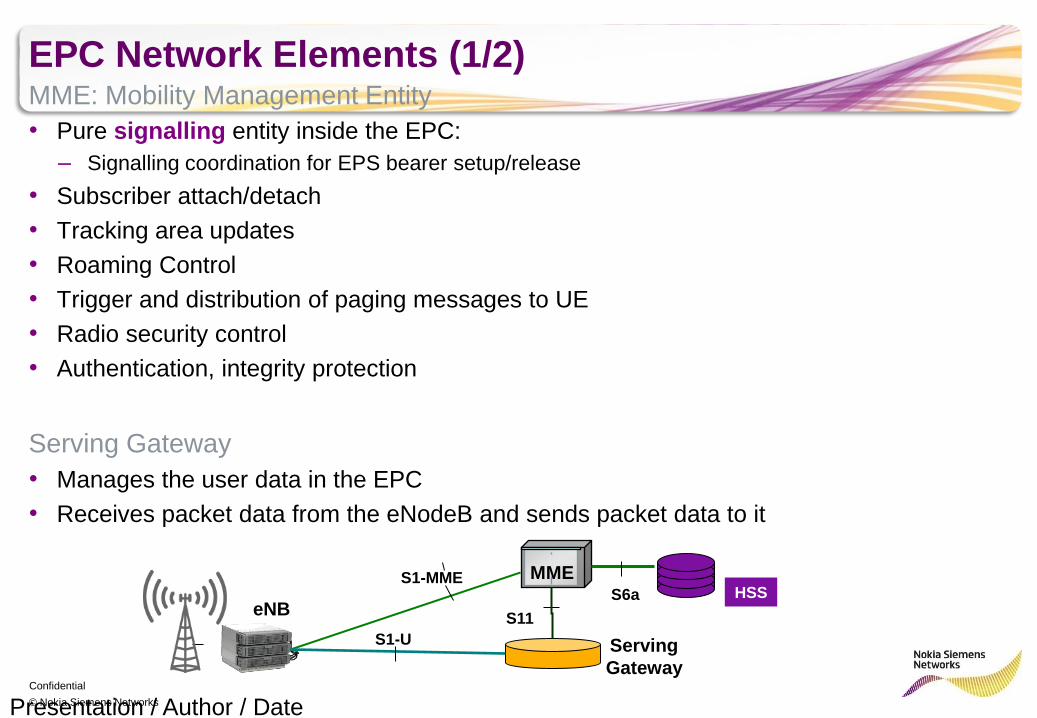
EPC Network Elements (1/2) MME: Mobility Management Entity
• Pure signalling entity inside the EPC:
– Signalling coordination for EPS bearer setup/release
• Subscriber attach/detach
• Tracking area updates
• Roaming Control
• Trigger and distribution of paging messages to UE
• Radio security control
• Authentication, integrity protection
Serving Gateway
• Manages the user data in the EPC
• Receives packet data from the eNodeB and sends packet data to it
Presentation / Author / Date
HSS
eNB
MME
Serving
Gateway
S1-U
S1-MME
S11
S6a
Confidential
© Nokia Siemens Networks
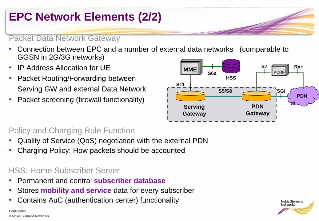
EPC Network Elements (2/2)
Packet Data Network Gateway
• Connection between EPC and a number of external data networks (comparable to GGSN in 2G/3G networks)
• IP Address Allocation for UE
• Packet Routing/Forwarding between
Serving GW and external Data Network
• Packet screening (firewall functionality)
Policy and Charging Rule Function
• Quality of Service (QoS) negotiation with the external PDN
• Charging Policy: How packets should be accounted
HSS: Home Subscriber Server
• Permanent and central subscriber database
• Stores mobility and service data for every subscriber
• Contains AuC (authentication center) functionality
MME
Serving
Gateway
S5/S8
PDN
Gateway
PDN SGi
PCRF
S7 Rx+
S11
HSS S6a
Confidential
© Nokia Siemens Networks
LTE Radio Interface and the X2 Interface
Presentation / Author / Date
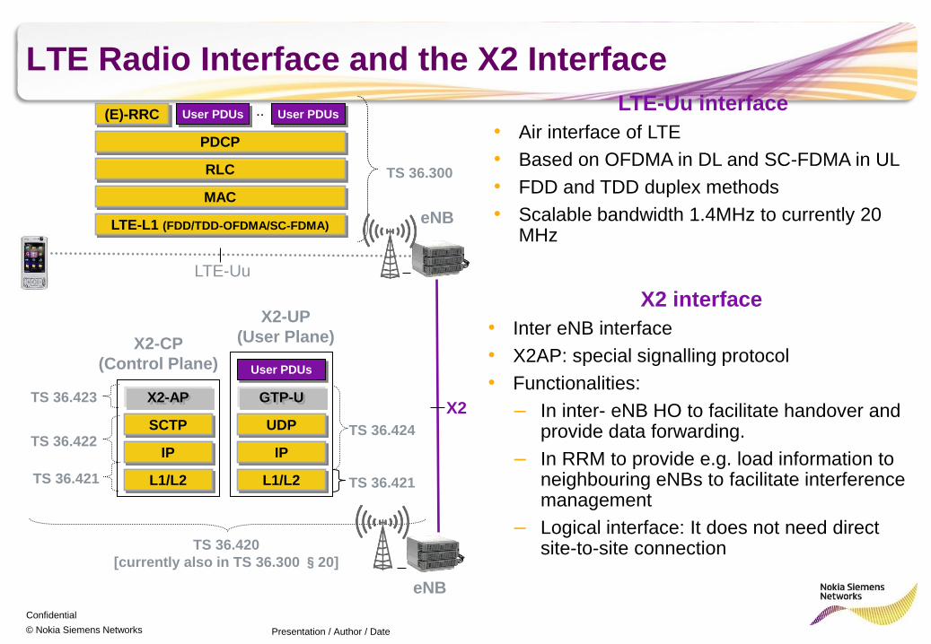
LTE-Uu interface
• Air interface of LTE
• Based on OFDMA in DL and SC-FDMA in UL
• FDD and TDD duplex methods
• Scalable bandwidth 1.4MHz to currently 20 MHz
X2 interface
• Inter eNB interface
• X2AP: special signalling protocol
• Functionalities:
– In inter- eNB HO to facilitate handover and provide data forwarding.
– In RRM to provide e.g. load information to neighbouring eNBs to facilitate interference management
– Logical interface: It does not need direct site-to-site connection
(E)-RRC User PDUs User PDUs
PDCP
..
RLC
MAC
LTE-L1 (FDD/TDD-OFDMA/SC-FDMA)
TS 36.300
eNB
LTE-Uu
eNB
X2
User PDUs
GTP-U
UDP
IP
L1/L2
TS 36.424
X2-UP
(User Plane) X2-CP
(Control Plane)
X2-AP
SCTP
IP
L1/L2 TS 36.421
TS 36.422
TS 36.423
TS 36.421
TS 36.420
[currently also in TS 36.300 §20]
Confidential
© Nokia Siemens Networks
Downlink Air Interface
OFDMA
Presentation / Author / Date
LTE Air Interface
Confidential
© Nokia Siemens Networks
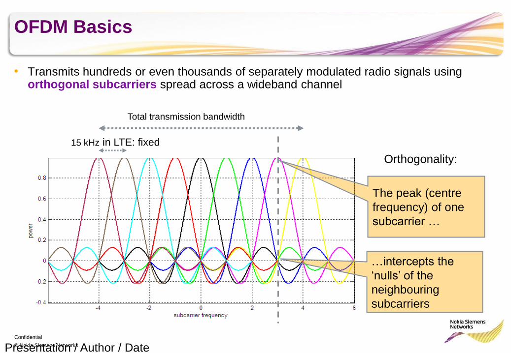
OFDM Basics
• Transmits hundreds or even thousands of separately modulated radio signals using orthogonal subcarriers spread across a wideband channel
Presentation / Author / Date
Orthogonality:
The peak (centre
frequency) of one
subcarrier …
…intercepts the
‘nulls’ of the
neighbouring
subcarriers
15 kHz in LTE: fixed
Total transmission bandwidth
Confidential
© Nokia Siemens Networks
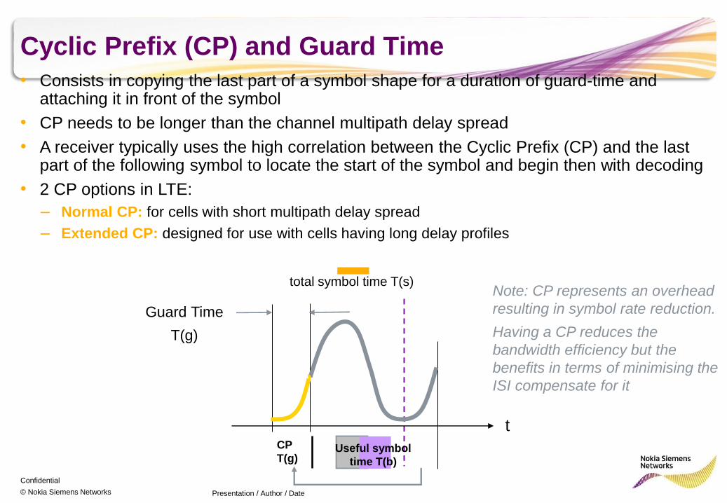
Cyclic Prefix (CP) and Guard Time
Presentation / Author / Date
Note: CP represents an overhead
resulting in symbol rate reduction.
Having a CP reduces the
bandwidth efficiency but the
benefits in terms of minimising the
ISI compensate for it
t
total symbol time T(s)
Guard Time
T(g)
CP
T(g) Useful symbol
time T(b)
• Consists in copying the last part of a symbol shape for a duration of guard-time and attaching it in front of the symbol
• CP needs to be longer than the channel multipath delay spread
• A receiver typically uses the high correlation between the Cyclic Prefix (CP) and the last part of the following symbol to locate the start of the symbol and begin then with decoding
• 2 CP options in LTE:
– Normal CP: for cells with short multipath delay spread
– Extended CP: designed for use with cells having long delay profiles
Confidential
© Nokia Siemens Networks
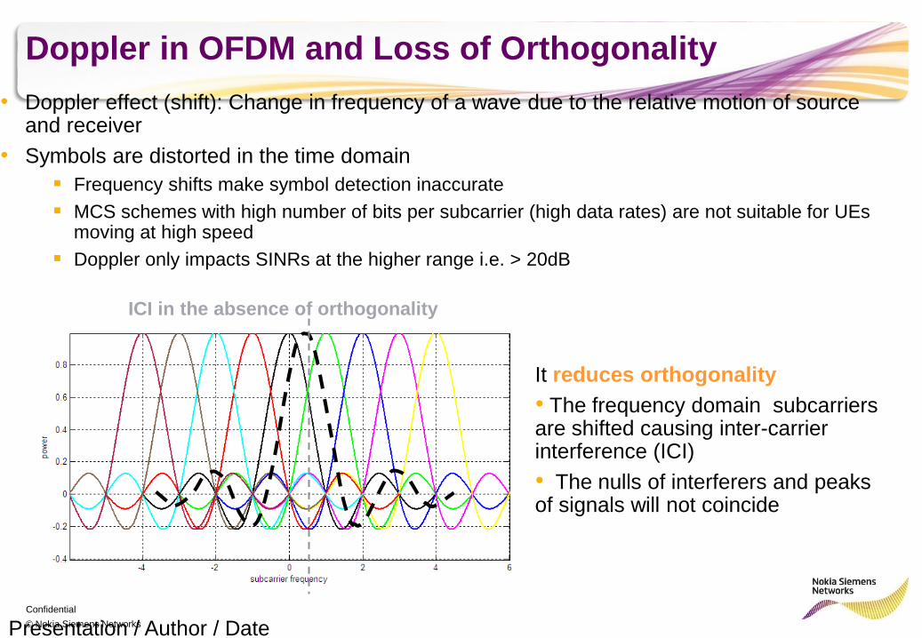
Doppler in OFDM and Loss of Orthogonality
• Doppler effect (shift): Change in frequency of a wave due to the relative motion of source and receiver
• Symbols are distorted in the time domain
Frequency shifts make symbol detection inaccurate
MCS schemes with high number of bits per subcarrier (high data rates) are not suitable for UEs moving at high speed
Doppler only impacts SINRs at the higher range i.e. > 20dB
Presentation / Author / Date
It reduces orthogonality
• The frequency domain subcarriers are shifted causing inter-carrier interference (ICI)
• The nulls of interferers and peaks of signals will not coincide
ICI in the absence of orthogonality
Confidential
© Nokia Siemens Networks
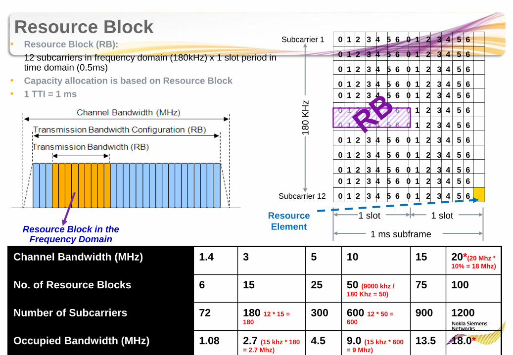
Resource Block
Channel Bandwidth (MHz) 1.4 3 5 10 15 20*(20 Mhz *
10% = 18 Mhz)
No. of Resource Blocks 6 15 25 50 (9000 khz /
180 Khz = 50)
75 100
Number of Subcarriers 72 180 12 * 15 =
180
300 600 12 * 50 =
600
900 1200
Occupied Bandwidth (MHz) 1.08 2.7 (15 khz * 180
= 2.7 Mhz)
4.5 9.0 (15 khz * 600
= 9 Mhz)
13.5 18.0*
Resource Block in the Frequency Domain
0 1 2 3 4 5 6 0 1 2 3 4 5 6
0 1 2 3 4 5 6 0 1 2 3 4 5 6
0 1 2 3 4 5 6 0 1 2 3 4 5 6
0 1 2 3 4 5 6 0 1 2 3 4 5 6
0 1 2 3 4 5 6 0 1 2 3 4 5 6
0 1 2 3 4 5 6 0 1 2 3 4 5 6
0 1 2 3 4 5 6 0 1 2 3 4 5 6
0 1 2 3 4 5 6 0 1 2 3 4 5 6
0 1 2 3 4 5 6 0 1 2 3 4 5 6
0 1 2 3 4 5 6 0 1 2 3 4 5 6
0 1 2 3 4 5 6 0 1 2 3 4 5 6
0 1 2 3 4 5 6 0 1 2 3 4 5 6
Subcarrier 1
Subcarrier 12
18
0 K
Hz
1 slot 1 slot
1 ms subframe
• Resource Block (RB):
12 subcarriers in frequency domain (180kHz) x 1 slot period in time domain (0.5ms)
• Capacity allocation is based on Resource Block
• 1 TTI = 1 ms
Resource
Element
Confidential
© Nokia Siemens Networks
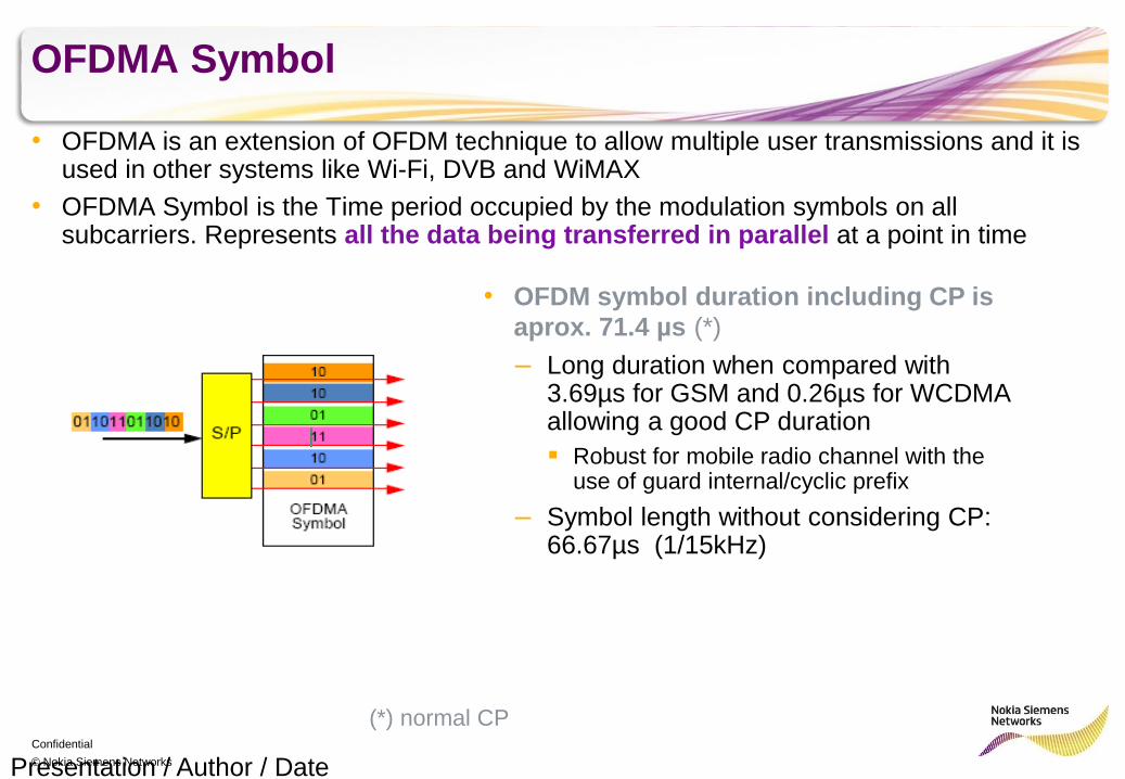
OFDMA Symbol
• OFDMA is an extension of OFDM technique to allow multiple user transmissions and it is used in other systems like Wi-Fi, DVB and WiMAX
• OFDMA Symbol is the Time period occupied by the modulation symbols on all subcarriers. Represents all the data being transferred in parallel at a point in time
Presentation / Author / Date
• OFDM symbol duration including CP is
aprox. 71.4 µs (*)
– Long duration when compared with 3.69µs for GSM and 0.26µs for WCDMA allowing a good CP duration
Robust for mobile radio channel with the use of guard internal/cyclic prefix
– Symbol length without considering CP: 66.67µs (1/15kHz)
(*) normal CP
Confidential
© Nokia Siemens Networks
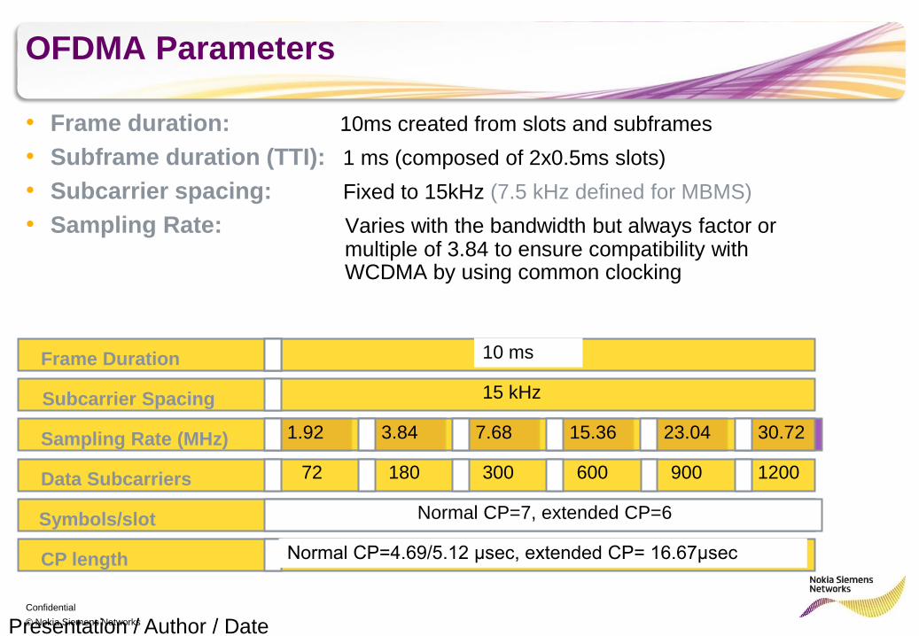
OFDMA Parameters
• Frame duration: 10ms created from slots and subframes
• Subframe duration (TTI): 1 ms (composed of 2x0.5ms slots)
• Subcarrier spacing: Fixed to 15kHz (7.5 kHz defined for MBMS)
• Sampling Rate: Varies with the bandwidth but always factor or multiple of 3.84 to ensure compatibility with WCDMA by using common clocking
Presentation / Author / Date
Frame Duration
Subcarrier Spacing
Sampling Rate (MHz)
Data Subcarriers
Symbols/slot
CP length
1.4MHz 3 MHz 5 MHz 10 MHz 15 MHz 20 MHz
10 ms
15 kHz
Normal CP=7, extended CP=6
Normal CP=4.69/5.12 μsec, extended CP= 16.67μsec
1.92 3.84 7.68 15.36 23.04 30.72
72 180 300 600 900 1200
Confidential
© Nokia Siemens Networks
Uplink Air Interface
SC-FDMA
Presentation / Author / Date
Confidential
© Nokia Siemens Networks
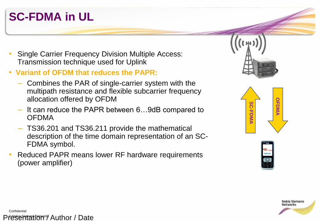
SC-FDMA in UL
• Single Carrier Frequency Division Multiple Access: Transmission technique used for Uplink
• Variant of OFDM that reduces the PAPR:
– Combines the PAR of single-carrier system with the multipath resistance and flexible subcarrier frequency allocation offered by OFDM
– It can reduce the PAPR between 6…9dB compared to OFDMA
– TS36.201 and TS36.211 provide the mathematical description of the time domain representation of an SC-FDMA symbol.
• Reduced PAPR means lower RF hardware requirements (power amplifier)
Presentation / Author / Date
SC
-FD
MA
OF
DM
A
Confidential
© Nokia Siemens Networks
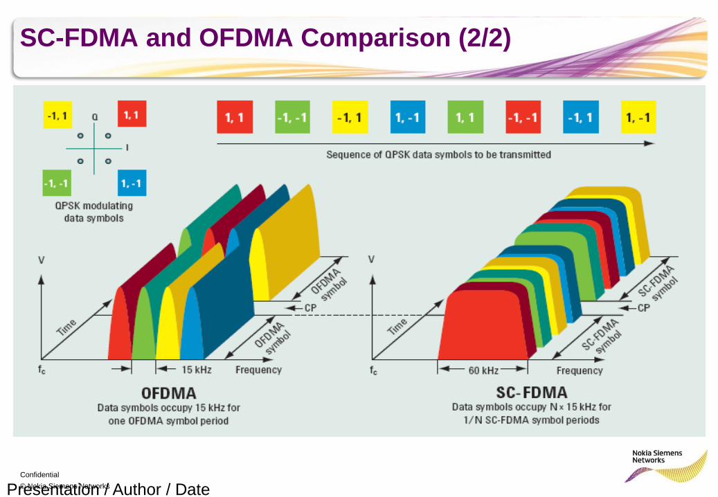
SC-FDMA and OFDMA Comparison (2/2)
Presentation / Author / Date

Confidential
© Nokia Siemens Networks
Uplink Air Interface Technology SC-FDMA
• User multiplexing in frequency domain, a user is allocated different bandwidths (multiples of 180kHz)
– In OFDMA the user multiplexing is in sub-carrier domain: user is allocated Resource Blocks
• One user is always continuous in frequency
• Smallest uplink bandwidth, 12 subcarriers: 180 kHz
– same for OFDMA in downlink
Presentation / Author / Date
• Largest uplink bandwidth: 20 MHz
– same for OFDMA in downlink
– Terminals are required to be able to receive & transmit up to 20 MHz
Confidential
© Nokia Siemens Networks
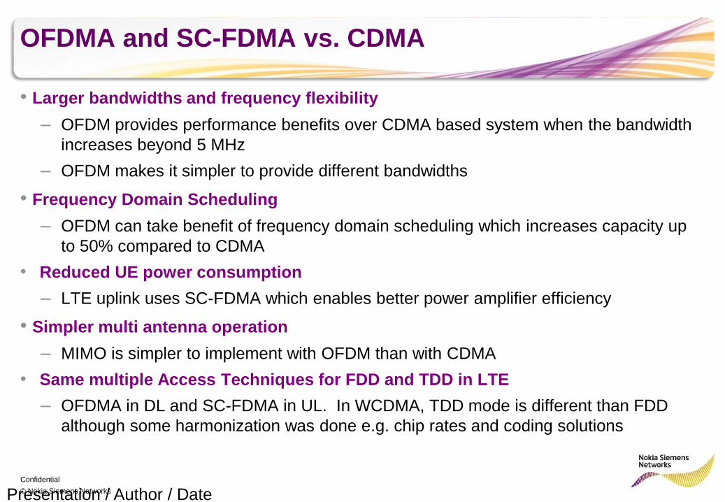
OFDMA and SC-FDMA vs. CDMA
• Larger bandwidths and frequency flexibility
– OFDM provides performance benefits over CDMA based system when the bandwidth
increases beyond 5 MHz
– OFDM makes it simpler to provide different bandwidths
• Frequency Domain Scheduling
– OFDM can take benefit of frequency domain scheduling which increases capacity up
to 50% compared to CDMA
• Reduced UE power consumption
– LTE uplink uses SC-FDMA which enables better power amplifier efficiency
• Simpler multi antenna operation
– MIMO is simpler to implement with OFDM than with CDMA
• Same multiple Access Techniques for FDD and TDD in LTE
– OFDMA in DL and SC-FDMA in UL. In WCDMA, TDD mode is different than FDD
although some harmonization was done e.g. chip rates and coding solutions
Presentation / Author / Date
Confidential
© Nokia Siemens Networks
Physical Layer Structure and Channels
Presentation / Author / Date
Physical Layer
Confidential
© Nokia Siemens Networks
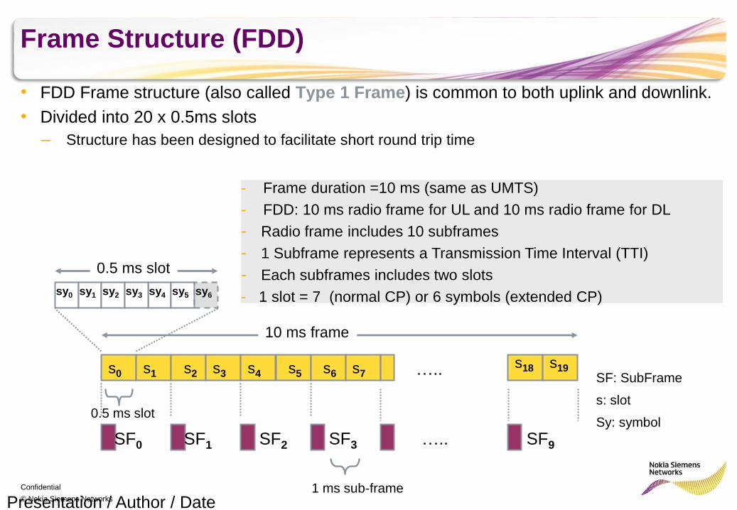
Frame Structure (FDD)
• FDD Frame structure (also called Type 1 Frame) is common to both uplink and downlink.
• Divided into 20 x 0.5ms slots
– Structure has been designed to facilitate short round trip time
Presentation / Author / Date
10 ms frame
0.5 ms slot
s0 s1 s2 s3 s4 s5 s6 s7 s18 s19 …..
1 ms sub-frame
SF0 SF1 SF2 SF9 …..
sy4 sy0 sy1 sy2 sy3 sy5 sy6
0.5 ms slot
SF3
- Frame duration =10 ms (same as UMTS)
- FDD: 10 ms radio frame for UL and 10 ms radio frame for DL
- Radio frame includes 10 subframes
- 1 Subframe represents a Transmission Time Interval (TTI)
- Each subframes includes two slots
- 1 slot = 7 (normal CP) or 6 symbols (extended CP)
SF: SubFrame
s: slot
Sy: symbol
Confidential
© Nokia Siemens Networks
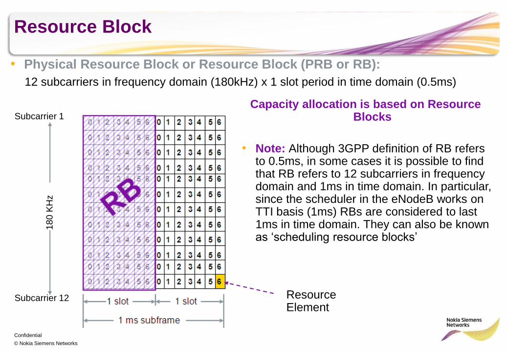
Resource Block
• Physical Resource Block or Resource Block (PRB or RB):
12 subcarriers in frequency domain (180kHz) x 1 slot period in time domain (0.5ms)
Subcarrier 1
Subcarrier 12
18
0 K
Hz
Capacity allocation is based on Resource Blocks
Resource Element
• Note: Although 3GPP definition of RB refers to 0.5ms, in some cases it is possible to find that RB refers to 12 subcarriers in frequency domain and 1ms in time domain. In particular, since the scheduler in the eNodeB works on TTI basis (1ms) RBs are considered to last 1ms in time domain. They can also be known as ‘scheduling resource blocks’
Confidential
© Nokia Siemens Networks
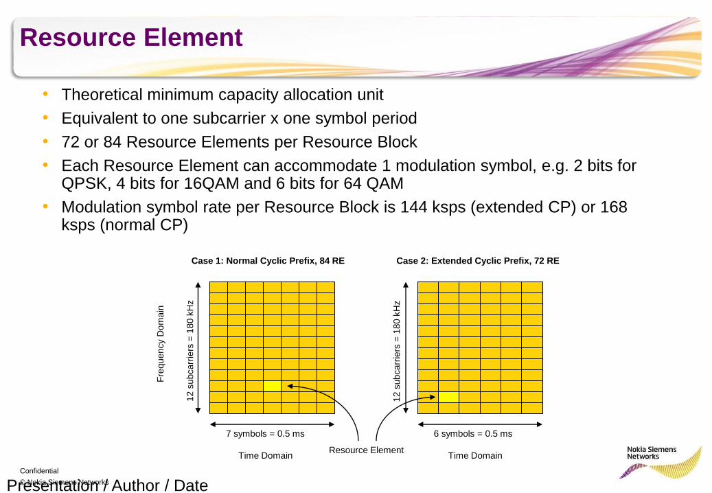
Resource Element
• Theoretical minimum capacity allocation unit
• Equivalent to one subcarrier x one symbol period
• 72 or 84 Resource Elements per Resource Block
• Each Resource Element can accommodate 1 modulation symbol, e.g. 2 bits for QPSK, 4 bits for 16QAM and 6 bits for 64 QAM
• Modulation symbol rate per Resource Block is 144 ksps (extended CP) or 168 ksps (normal CP)
Presentation / Author / Date
Case 1: Normal Cyclic Prefix, 84 RE Case 2: Extended Cyclic Prefix, 72 RE
7 symbols = 0.5 ms 6 symbols = 0.5 ms
Fre
quency D
om
ain
12 s
ubcarr
iers
= 1
80 k
Hz
Resource Element
12 s
ubcarr
iers
= 1
80 k
Hz
Time Domain Time Domain
Confidential
© Nokia Siemens Networks
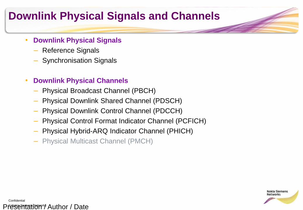
Downlink Physical Signals and Channels
• Downlink Physical Signals
– Reference Signals
– Synchronisation Signals
• Downlink Physical Channels
– Physical Broadcast Channel (PBCH)
– Physical Downlink Shared Channel (PDSCH)
– Physical Downlink Control Channel (PDCCH)
– Physical Control Format Indicator Channel (PCFICH)
– Physical Hybrid-ARQ Indicator Channel (PHICH)
– Physical Multicast Channel (PMCH)
Presentation / Author / Date
Confidential
© Nokia Siemens Networks
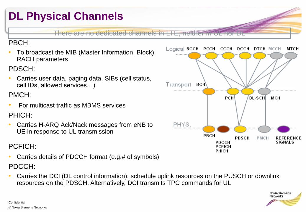
DL Physical Channels
PBCH:
• To broadcast the MIB (Master Information Block), RACH parameters
PDSCH:
• Carries user data, paging data, SIBs (cell status, cell IDs, allowed services…)
PMCH:
• For multicast traffic as MBMS services
PHICH:
• Carries H-ARQ Ack/Nack messages from eNB to UE in response to UL transmission
There are no dedicated channels in LTE, neither in UL nor DL
PCFICH: • Carries details of PDCCH format (e.g.# of symbols)
PDCCH:
• Carries the DCI (DL control information): schedule uplink resources on the PUSCH or downlink resources on the PDSCH. Alternatively, DCI transmits TPC commands for UL

Confidential
© Nokia Siemens Networks
Mapping of DL Physical Channels (I)
• PBCH:
– Occupies the central 72 subcarriers across 4 symbols
– Transmitted during second slot of each 10 ms radio frame on all antennas
• PCFICH:
– Can be transmitted during the first 3 symbols of
each TTI
– Occupies up to 16 RE per TTI
• PHICH:
– Normal CP: Tx during 1st symbol of each TTI
– Extended CP: Tx during first 3 symbols of each TTI
• PDCCH:
– Occupies the RE left from PCFICH and PHICH within the first 3 symbols of each TTI
– Minimum number of symbols are occupied. If PDCCH data is small then it only occupies the 1st symbol
• PDSCH:
– Is allocated the RE not used by signals or other physical channels
Presentation / Author / Date
RB
Confidential
© Nokia Siemens Networks
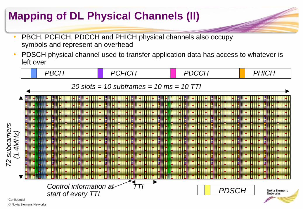
Mapping of DL Physical Channels (II)
PBCH PDCCH PCFICH PHICH
20 slots = 10 subframes = 10 ms = 10 TTI
72 s
ubcarr
iers
(1
.4M
Hz)
PDSCH
• PDSCH physical channel used to transfer application data has access to whatever is left over
• PBCH, PCFICH, PDCCH and PHICH physical channels also occupy symbols and represent an overhead
TTI Control information at start of every TTI
Confidential
© Nokia Siemens Networks
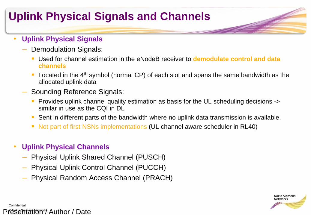
Uplink Physical Signals and Channels
• Uplink Physical Signals
– Demodulation Signals:
Used for channel estimation in the eNodeB receiver to demodulate control and data channels
Located in the 4th symbol (normal CP) of each slot and spans the same bandwidth as the allocated uplink data
– Sounding Reference Signals:
Provides uplink channel quality estimation as basis for the UL scheduling decisions -> similar in use as the CQI in DL
Sent in different parts of the bandwidth where no uplink data transmission is available.
Not part of first NSNs implementations (UL channel aware scheduler in RL40)
• Uplink Physical Channels
– Physical Uplink Shared Channel (PUSCH)
– Physical Uplink Control Channel (PUCCH)
– Physical Random Access Channel (PRACH)
Presentation / Author / Date
Confidential
© Nokia Siemens Networks
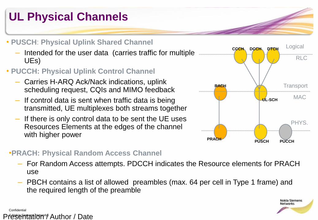
UL Physical Channels
• PUSCH: Physical Uplink Shared Channel
– Intended for the user data (carries traffic for multiple UEs)
• PUCCH: Physical Uplink Control Channel
– Carries H-ARQ Ack/Nack indications, uplink scheduling request, CQIs and MIMO feedback
– If control data is sent when traffic data is being transmitted, UE multiplexes both streams together
– If there is only control data to be sent the UE uses Resources Elements at the edges of the channel with higher power
Presentation / Author / Date
RACH
CCCH DCCH DTCH
UL-SCH
PRACH PUSCH PUCCH
Logical
Transport
PHYS.
RLC
MAC
•PRACH: Physical Random Access Channel
– For Random Access attempts. PDCCH indicates the Resource elements for PRACH use
– PBCH contains a list of allowed preambles (max. 64 per cell in Type 1 frame) and the required length of the preamble
Confidential
© Nokia Siemens Networks
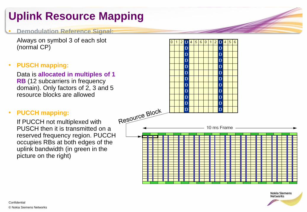
Uplink Resource Mapping
• Demodulation Reference Signal:
Always on symbol 3 of each slot (normal CP)
• PUSCH mapping:
Data is allocated in multiples of 1 RB (12 subcarriers in frequency domain). Only factors of 2, 3 and 5 resource blocks are allowed
• PUCCH mapping:
If PUCCH not multiplexed with PUSCH then it is transmitted on a reserved frequency region. PUCCH occupies RBs at both edges of the uplink bandwidth (in green in the picture on the right)
Confidential
© Nokia Siemens Networks
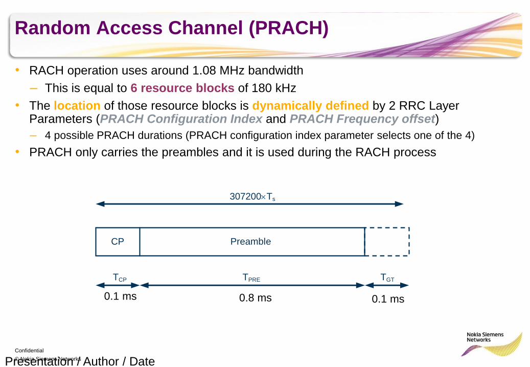
Random Access Channel (PRACH)
• RACH operation uses around 1.08 MHz bandwidth
– This is equal to 6 resource blocks of 180 kHz
• The location of those resource blocks is dynamically defined by 2 RRC Layer Parameters (PRACH Configuration Index and PRACH Frequency offset)
– 4 possible PRACH durations (PRACH configuration index parameter selects one of the 4)
• PRACH only carries the preambles and it is used during the RACH process
Presentation / Author / Date
307200Ts
TPRE TGT TCP
Preamble CP
0.1 ms 0.1 ms 0.8 ms
Confidential
© Nokia Siemens Networks Presentation / Author / Date
b0 b1
QPSK
Im
Re 10
11
00
01
b0 b1b2b3
16QAM
Im
Re
0000
1111
Im
Re
64QAM
b0 b1b2b3 b4 b5
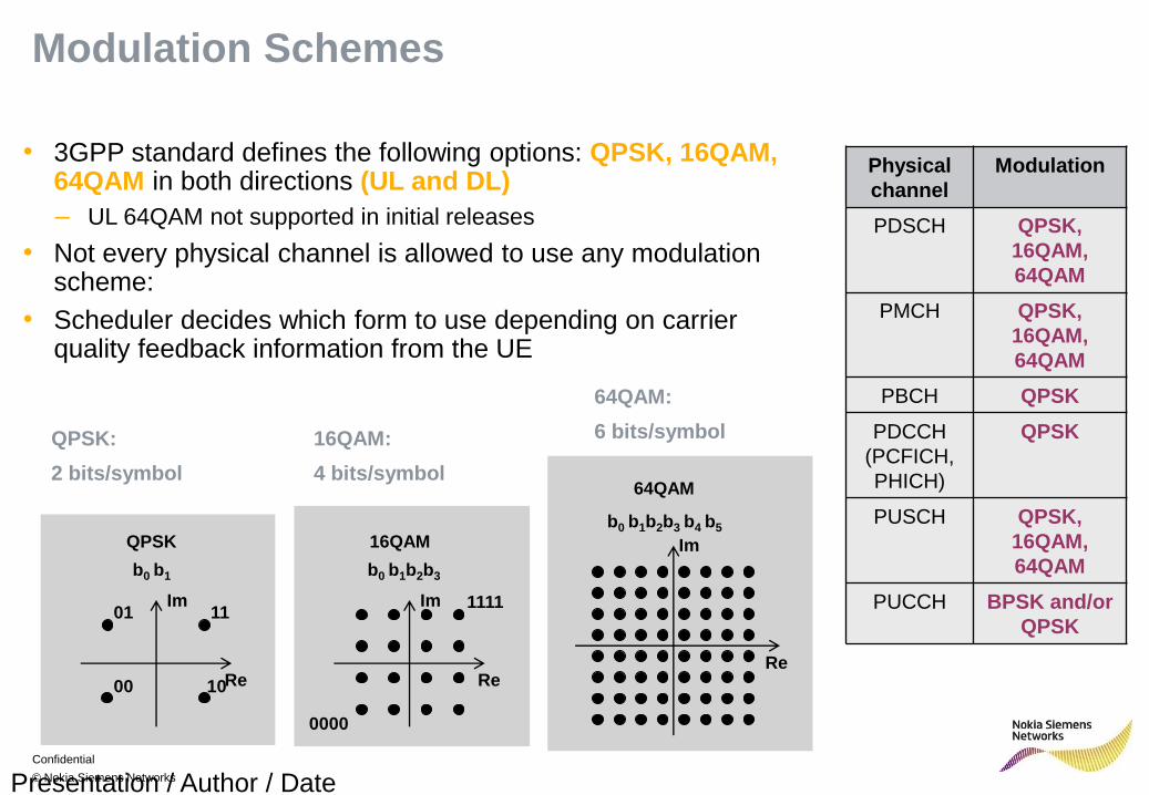
• 3GPP standard defines the following options: QPSK, 16QAM, 64QAM in both directions (UL and DL)
– UL 64QAM not supported in initial releases
• Not every physical channel is allowed to use any modulation scheme:
• Scheduler decides which form to use depending on carrier quality feedback information from the UE
Modulation Schemes
QPSK:
2 bits/symbol
16QAM:
4 bits/symbol
64QAM:
6 bits/symbol
Physical
channel
Modulation
PDSCH QPSK,
16QAM,
64QAM
PMCH QPSK,
16QAM,
64QAM
PBCH QPSK
PDCCH
(PCFICH,
PHICH)
QPSK
PUSCH QPSK,
16QAM,
64QAM
PUCCH BPSK and/or
QPSK
Confidential
© Nokia Siemens Networks
LTE UE Connection Management Overview
Presentation / Author / Date
Confidential
© Nokia Siemens Networks
Mobility and Connection States (1/2)
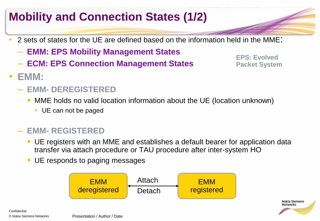
• 2 sets of states for the UE are defined based on the information held in the MME:
– EMM: EPS Mobility Management States
– ECM: EPS Connection Management States
• EMM:
– EMM- DEREGISTERED
MME holds no valid location information about the UE (location unknown)
• UE can not be paged
– EMM- REGISTERED
UE registers with an MME and establishes a default bearer for application data transfer via attach procedure or TAU procedure after inter-system HO
UE responds to paging messages
Presentation / Author / Date
EMM deregistered
EMM registered
Attach
Detach
EPS: Evolved Packet System
Confidential
© Nokia Siemens Networks
Mobility and Connection States (2/2)
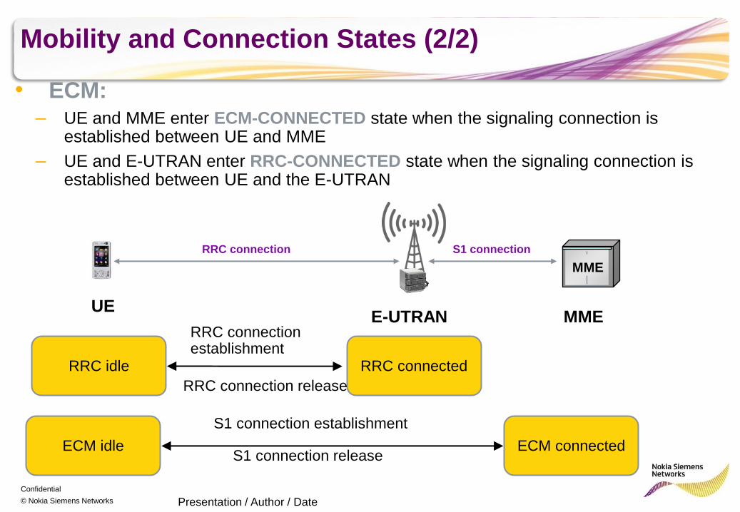
• ECM: – UE and MME enter ECM-CONNECTED state when the signaling connection is
established between UE and MME
– UE and E-UTRAN enter RRC-CONNECTED state when the signaling connection is established between UE and the E-UTRAN
Presentation / Author / Date
ECM idle ECM connected
S1 connection establishment
S1 connection release
RRC idle RRC connected
RRC connection establishment
RRC connection release
UE E-UTRAN MME
MME
S1 connection RRC connection
Confidential
© Nokia Siemens Networks
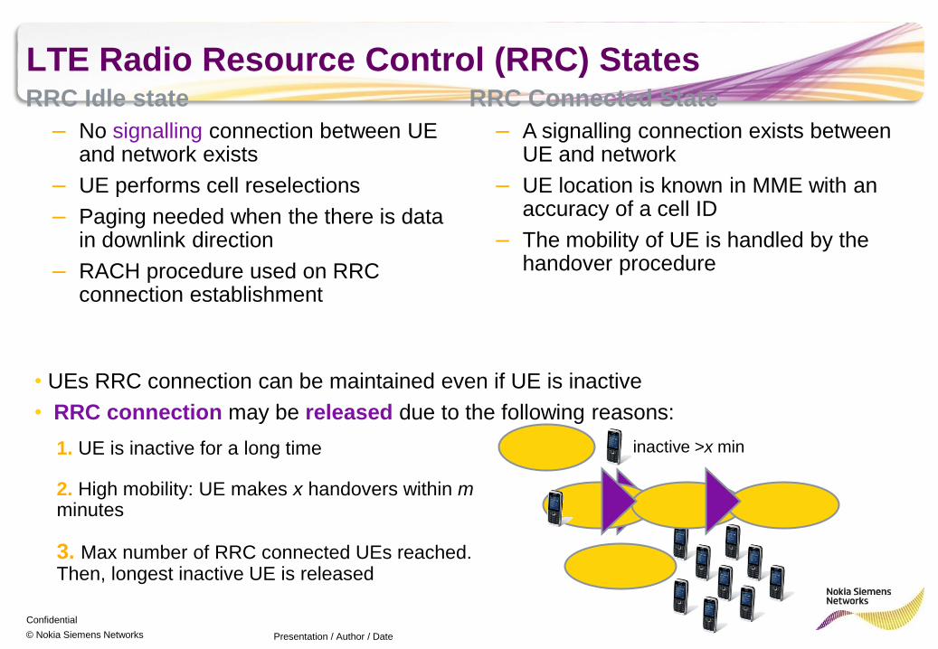
LTE Radio Resource Control (RRC) States RRC Idle state
– No signalling connection between UE and network exists
– UE performs cell reselections
– Paging needed when the there is data in downlink direction
– RACH procedure used on RRC connection establishment
Presentation / Author / Date
• UEs RRC connection can be maintained even if UE is inactive
• RRC connection may be released due to the following reasons:
RRC Connected State
– A signalling connection exists between UE and network
– UE location is known in MME with an accuracy of a cell ID
– The mobility of UE is handled by the handover procedure
inactive >x min
2. High mobility: UE makes x handovers within m minutes
1. UE is inactive for a long time
3. Max number of RRC connected UEs reached. Then, longest inactive UE is released
Confidential
© Nokia Siemens Networks
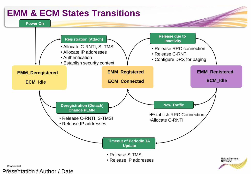
EMM & ECM States Transitions
Presentation / Author / Date
EMM_Deregistered
ECM_Idle
Power On
Registration (Attach)
EMM_Registered
ECM_Connected
• Allocate C-RNTI, S_TMSI
• Allocate IP addresses
• Authentication
• Establish security context
• Release RRC connection
• Release C-RNTI
• Configure DRX for paging
EMM_Registered
ECM_Idle
Release due to
Inactivity
•Establish RRC Connection
•Allocate C-RNTI
New Traffic Deregistration (Detach)
Change PLMN
• Release C-RNTI, S-TMSI
• Release IP addresses
Timeout of Periodic TA
Update
• Release S-TMSI
• Release IP addresses
Confidential
© Nokia Siemens Networks
LTE Mobility Management
Presentation / Author / Date
Confidential
© Nokia Siemens Networks
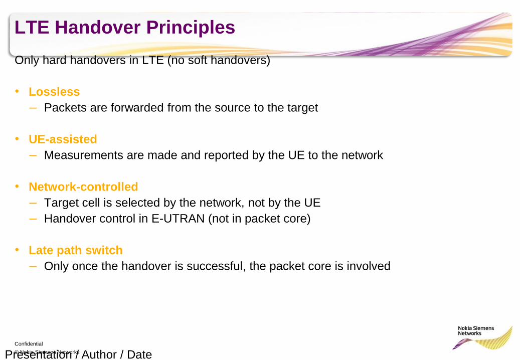
LTE Handover Principles
Only hard handovers in LTE (no soft handovers)
• Lossless
– Packets are forwarded from the source to the target
• UE-assisted
– Measurements are made and reported by the UE to the network
• Network-controlled
– Target cell is selected by the network, not by the UE
– Handover control in E-UTRAN (not in packet core)
• Late path switch
– Only once the handover is successful, the packet core is involved
Presentation / Author / Date
Confidential
© Nokia Siemens Networks
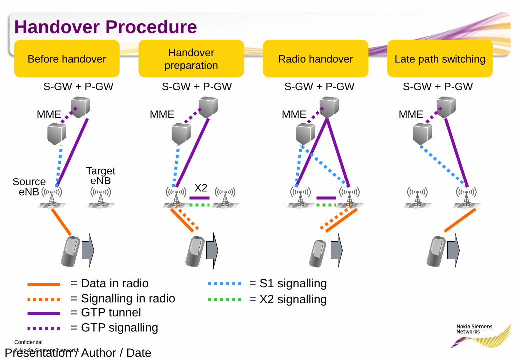
Handover Procedure
Presentation / Author / Date
S-GW + P-GW
MME
Source eNB
Target eNB
MME MME MME
= Data in radio
= Signalling in radio = GTP tunnel
= GTP signalling
= S1 signalling
= X2 signalling
Before handover Handover
preparation Radio handover Late path switching
S-GW + P-GW S-GW + P-GW S-GW + P-GW
X2
Confidential
© Nokia Siemens Networks
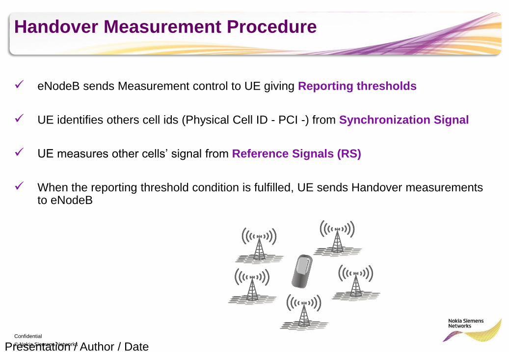
Handover Measurement Procedure
eNodeB sends Measurement control to UE giving Reporting thresholds
UE identifies others cell ids (Physical Cell ID - PCI -) from Synchronization Signal
UE measures other cells’ signal from Reference Signals (RS)
When the reporting threshold condition is fulfilled, UE sends Handover measurements to eNodeB
Presentation / Author / Date
Confidential
© Nokia Siemens Networks
Thank You