LTE Measurements Application Note - dl.cdn-anritsu.com · Measurement point E-UTRA ACLR1 UTRA ACLR1...
391
Revision History Ver. No Date Contents Related product software version 1.00 May 2015 MT8820C/21C LTE Application Note (Ver. 1.00) is based on MT8820C LTE Application Note (Ver. 15.00). Overall: Added MT8821C option model names to MT8820C option model names Overall: Added DL CA and UL CA test procedures for MT8821C Added MT8821C software specification. MX882012C/42C Ver. 23.20 MX882112C/42C Ver. 30.00 2.00 Sep 2015 • 1.5.2 Added FDD-TDD 2,3DL/1UL CA, SISO and MIMO to Supported CA Combination of MT8821C. • 2.4 / 3.6 / 5.3 Added MT8821C connection/RX-measurement/ IP-data-transfer-test procedures for 4DL CA. • 3.3 Added MT8821C measurement procedures for Inter-band UL CA. • 3.7 Added MT8821C UL Throughput measurement procedure for SCC. • 7 Added MT8821C VoLTE Echoback test procedure. • Annex B.2 Added mention of Carrier Leakage Frequency for measurements on MT8821C intra-band contiguous CC. • Annex B.3 Added description about optimization of TCP Throughput by Iperf. • AnnexB.4 Added maximum rate setting for DL 256QAM. MX882012C/42C Ver23.20 MX882112C/42C Ver30.10 3.00 Dec 2015 • 1.2 Supported 6.2.3_2, 6.6.2.1_1, 6.6.2.3_2 of 3GPP Measurement Specification for MT8820C • 2.2 Added MT8820C setting procedures for FDD-TDD 2DL/1UL CA. • 3.4.1 Modified test procedures for MT8820C. • 3.4.5 Modified test procedures for MT8820C. MX882012C/42C Ver23.30 MX882112C/42C Ver30.12 4.00 Jan 2016 • 8 Added MT8821C SMS test procedure. MX882012C/42C Ver23.30 MX882112C/42C Ver30.20 Application Note LTE Measurements Radio Communication Analyzer MT8820C/MT8821C
Transcript of LTE Measurements Application Note - dl.cdn-anritsu.com · Measurement point E-UTRA ACLR1 UTRA ACLR1...
Revision History
Ver. No
Date Contents Related product software version
1.00 May 2015 MT8820C/21C LTE Application Note (Ver. 1.00) is based on MT8820C LTE Application Note (Ver. 15.00). Overall: Added MT8821C option model names to MT8820C option model names Overall: Added DL CA and UL CA test procedures for MT8821C Added MT8821C software specification.
MX882012C/42C Ver. 23.20 MX882112C/42C Ver. 30.00
2.00 Sep 2015 • 1.5.2 Added FDD-TDD 2,3DL/1UL CA, SISO and MIMO to Supported CA Combination of MT8821C. • 2.4 / 3.6 / 5.3 Added MT8821C connection/RX-measurement/ IP-data-transfer-test procedures for 4DL CA. • 3.3 Added MT8821C measurement procedures for Inter-band UL CA. • 3.7 Added MT8821C UL Throughput measurement procedure for SCC. • 7 Added MT8821C VoLTE Echoback test procedure. • Annex B.2 Added mention of Carrier Leakage Frequency for measurements on MT8821C intra-band contiguous CC. • Annex B.3 Added description about optimization of TCP
Throughput by Iperf. • AnnexB.4 Added maximum rate setting for DL 256QAM.
MX882012C/42C Ver23.20 MX882112C/42C Ver30.10
3.00 Dec 2015 • 1.2 Supported 6.2.3_2, 6.6.2.1_1, 6.6.2.3_2 of 3GPP Measurement Specification for MT8820C • 2.2 Added MT8820C setting procedures for FDD-TDD 2DL/1UL CA. • 3.4.1 Modified test procedures for MT8820C. • 3.4.5 Modified test procedures for MT8820C.
MX882012C/42C Ver23.30 MX882112C/42C Ver30.12
4.00 Jan 2016 • 8 Added MT8821C SMS test procedure. MX882012C/42C Ver23.30 MX882112C/42C Ver30.20
Application Note
LTE Measurements Radio Communication Analyzer MT8820C/MT8821C
5.00 Mar 2016 • 1.2 Updated 3GPP measurement standard list (2015-12) • 1.3 Added Band 45, 65-67. • 1.5.2 / 2.5 / 3.7 Added 5DL CA test procedures. • 3.3 / 3.4 / 3.5 Added test procedures associated with updating 3GPP measurement standard list. • 5.4 Added IP Data Application. • 8 Added 4x4 MIMO test procedures.
MX882012C/42C Ver23.30 MX882112C/42C Ver30.30
6.00 Jun 2016 • 1.2 Supported 7.4A.3_H,7.4A.4_H of 3GPP Measurement Specification for MT8821C. • 3.4 Added 7.4A.3_H,7.4A.4_H of 3GPP Measurement Specification for MT8821C test procedure. • 3.4.11 Modified test procedures.
MX882012C/42C Ver23.30 MX882112C/42C Ver30.32
7.00 Oct 2016 • 1.3 Added Band 66, 250. • 2.2.8.3 Added RB Allocation Detail Mode setting method. • 3.2 / 3.3 / 3.4 / 3.5 /3.6 Added test procedures associated with updating 3GPP measurement standard list (2016-03). • 3.3.2.11 Added test procedures associated with updating 3GPP measurement standard list (2016-06). • 9 Added 4x2 MIMO test procedure and Maximum Throughput setting method. • 10 Added CSAT measurement procedure. • 11 Added Antenna Selection measurement procedure. • B.1 Added 4x4 MIMO and DL256QAM conditions.
MX882012C/42C Ver23.30 MX882112C/42C Ver30.40
8.00 Oct 2017 • 1.3 Added Band 48, 68, 69, 70. • 1.1.2.16 / 1.5.2 Added 6DL CA condition. • 2.6, 3.8.2 Added test procedure and Connection Diagram for 5DL CA SISO/2x2MIMO with 2units. • 2.7, Added test procedure and Connection Diagram for 6DL CA SISO with 1unit (TBD) • 2.8 Added test procedure and Connection Diagram for 6DL CA SISO/2x2MIMO with 2units. • 3.3 Added test procedures associated with updating 3GPP measurement standard list. • 3.11 Added SRS(Sounding Reference Signal) Measurements • 3.12 Added RX test procedure for the case including LAA SCell. • 6.3.2.4 Added Measurement Report test procedure for any Intra-Frequencys and Inter-Frequencys. • 6.4 Added UE Capability Information Enquiry • 9.4 Added test procedure for 4DL CA 4x4 MIMO. • 12 Added LAA test procedure. • Annex B.1.2 Added Code Rate display function
MX882012C/42C Ver23.32 MX882112C/42C Ver30.60
2
Contents
LTE Measurement Software.......................................................................................... 5 1. SPECIFICATIONS ...................................................................................................................................... 5 1.1.
3GPP MEASUREMENT SPECIFICATION (3GPP TS 36.521-1 V12.8.0(2015-12)) TABLE .......................... 22 1.2.
OPERATION BANDS ................................................................................................................................ 40 1.3.
BAND 13 SUPPLEMENTARY RF CONFORMANCE MEASUREMENT SPECIFICATION TABLE ............... 42 1.4.
SUPPORTED CA COMBINATION .............................................................................................................. 42 1.5.
The Basic Operations ................................................................................................... 50 2. LTE NON CA ......................................................................................................................................... 50 2.1.
2DL CA WITHOUT UL CA/2DL CA WITH UL CA ...................................................................................... 53 2.2.
3DL CA ................................................................................................................................................ 70 2.3.
4DL CA ................................................................................................................................................ 81 2.4.
5DL CA (ONE MT8821C UNIT CONFIGURATION) ..................................................................................... 87 2.5.
5DL CA (TWO MT8821C UNITS CONFIGURATION) .................................................................................. 91 2.6.
6DL CA (ONE MT8821C UNIT CONFIGURATION) ................................................................................... 102 2.7.
6DL CA (TWO MT8821C UNITS CONFIGURATION) ................................................................................ 102 2.8.
TRX Measurements (Fundamental Measurements) ............................................. 113 3. TX MEASUREMENTS .............................................................................................................................113 3.1.
RX MEASUREMENTS ........................................................................................................................... 150 3.2.
TX MEASUREMENTS FOR CA ............................................................................................................... 154 3.3.
RX MEASUREMENTS FOR CA............................................................................................................... 194 3.4.
RX MEASUREMENTS FOR 3DL CA ....................................................................................................... 201 3.5.
RX MEASUREMENTS FOR 4DL CA ....................................................................................................... 219 3.6.
RX MEASUREMENTS FOR 5DL CA ....................................................................................................... 224 3.7.
RX MEASUREMENTS FOR MT8821C UL CA 2CCS .............................................................................. 225 3.8.
TEST PARAMETERS SUPPORTING 3GPP TEST ITEMS ............................................................................ 231 3.9.
REMOTE COMMANDS LIST SETTING PASS/FAIL JUDGMENT VALUES ..................................................... 237 3.10.
SRS (SOUNDING REFERENCE SIGNAL) MEASUREMENTS .................................................................... 248 3.11.
RX MEASUREMENTS FOR CA INCLUDING LAA SCELL ......................................................................... 249 3.12.
BAND 13 SUPPLEMENTARY RF CONFORMANCE MEASUREMENT ......................... 251 4. PUCCH OVER-PROVISIONING FUNCTIONAL TEST (2.7) ............................................................ 251 4.1.
SPURIOUS EMISSIONS WITH TX GATING (2.9) ............................................................................ 251 4.2.
IP Data Transfer Test ................................................................................................. 253 5. IP DATA TRANSFER TEST FOR NON CA (SINGLE CELL) .......................................................................... 253 5.1.
IP DATA TRANSFER TEST FOR 2DL CA ................................................................................................. 277 5.2.
IP DATA TRANSFER TEST FOR 3/4DL CA .............................................................................................. 294 5.3.
IP DATA APPLICATION .......................................................................................................................... 307 5.4.
3
RRM .............................................................................................................................. 309 6. 1PORT CS FALLBACK/REDIRECTION .................................................................................................... 309 6.1.
CELL RESELECTION ............................................................................................................................. 313 6.2.
MEASUREMENT REPORT ...................................................................................................................... 319 6.3.
UE CAPABILITY INFORMATION ENQUIRY................................................................................................ 322 6.4.
LTE VoLTE Echoback Test (MT8821C Only) .............................................................. 323 7. LTE VOLTE ECHOBACK TEST .............................................................................................................. 323 7.1.
SMS Test (MT8821C Only) .......................................................................................... 336 8. MT8821C UE SMS SEND ............................................................................................................... 336 8.1.
UE MT8821C SMS RECEIVE .......................................................................................................... 336 8.2.
4x2, 4x4 MIMO (MT8821C Only) ................................................................................ 337 9. 4X4 MIMO .......................................................................................................................................... 337 9.1.
4X2 MIMO .......................................................................................................................................... 340 9.2.
3DL CA WITHOUT UL CA ..................................................................................................................... 342 9.3.
4DL CA WITHOUT UL CA ..................................................................................................................... 349 9.4.
MAXIMUM THROUGHPUT ...................................................................................................................... 358 9.5.
IP DATA TRANSFER .............................................................................................................................. 359 9.6.
CSAT (MT8821C Only) ............................................................................................... 360 10. CSAT ............................................................................................................................................... 360 10.1.
ECSAT ............................................................................................................................................. 361 10.2.
Antenna Selection Connection and Measurement ............................................. 363 11. CONNECTION DIAGRAM ..................................................................................................................... 363 11.1.
CONNECTION AND MEASUREMENT PROCEDURE .................................................................................. 363 11.2.
LAA (MT8821C Only) ................................................................................................. 365 12. ALL SUBFRAME TRANSMISSION SETTING ............................................................................................ 365 12.1.
FLEXIBLE TRANSMISSION SCHEDULING SETTING ................................................................................ 366 12.2.
RX MEASUREMENT FOR REFERENCE SENSITIVITY/MAX INPUT LEVEL SETTING .................................... 368 12.3.
Annex A: ARB Waveform List ........................................................................................ 370
A.1. ARB WAVEFORM INSTALLER VERSION: Q007 ...................................................................................... 370 A.2. ARB WAVEFORM INSTALLER VERSION: Q008 ...................................................................................... 370
Annex B: Informative .................................................................................................... 372
B.1. UE DL-SCH RX ................................................................................................................................. 372 B.2. CARRIER LEAKAGE FREQUENCY .......................................................................................................... 386 B.3. ABOUT OPTIMIZATION OF THE TCP THROUGHPUT USING IPERF ............................................................. 388 B.4. SETTING FOR DL 256QAM MAXIMUM THROUGHPUT RATE ................................................................... 390
4
LTE Measurement Software 1. Specifications 1.1.
MT8820C 1.1.1.1.1.1.1. MX882012C/13C (Call Processing)
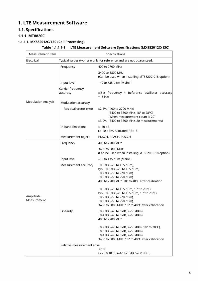
Table 1.1.1.1-1 LTE Measurement Software Specifications (MX882012C/13C)
Measurement Item Specifications
Electrical Typical values (typ.) are only for reference and are not guaranteed.
Modulation Analysis
Frequency 400 to 2700 MHz
3400 to 3800 MHz (Can be used when installing MT8820C-018 option)
Input level –40 to +35 dBm (Main1)
Carrier frequency accuracy ±(Set frequency × Reference oscillator accuracy +15 Hz)
Modulation accuracy
Residual vector error ≤2.5% (400 to 2700 MHz) (3400 to 3800 MHz, 18° to 28°C) (When measurement count is 20) ≤3.0% (3400 to 3800 MHz, 20 measurements)
In-band Emissions ≤–40 dB (≥–10 dBm, Allocated RB≤18)
Measurement object PUSCH, PRACH, PUCCH
Amplitude Measurement
Frequency 400 to 2700 MHz
3400 to 3800 MHz (Can be used when installing MT8820C-018 option)
Input level –60 to +35 dBm (Main1)
Measurement accuracy ±0.5 dB (–20 to +35 dBm), typ. ±0.3 dB (–20 to +35 dBm) ±0.7 dB (–50 to –20 dBm) ±0.9 dB (–60 to –50 dBm) 400 to 2700 MHz, 10° to 40°C after calibration ±0.5 dB (–20 to +35 dBm, 18° to 28°C), typ. ±0.3 dB (–20 to +35 dBm, 18° to 28°C), ±0.7 dB (–50 to –20 dBm), ±0.9 dB (–60 to –50 dBm), 3400 to 3800 MHz, 10° to 40°C after calibration
Linearity ±0.2 dB (–40 to 0 dB, ≥–50 dBm) ±0.4 dB (–40 to 0 dB, ≥–60 dBm) 400 to 2700 MHz ±0.2 dB (–40 to 0 dB, ≥–50 dBm, 18° to 28°C), ±0.3 dB (–40 to 0 dB, ≥–50 dBm) ±0.4 dB (–40 to 0 dB, ≥–60 dBm) 3400 to 3800 MHz, 10° to 40°C after calibration
Relative measurement error <2 dB typ. ±0.10 dB (–40 to 0 dB, ≥–50 dBm)
5
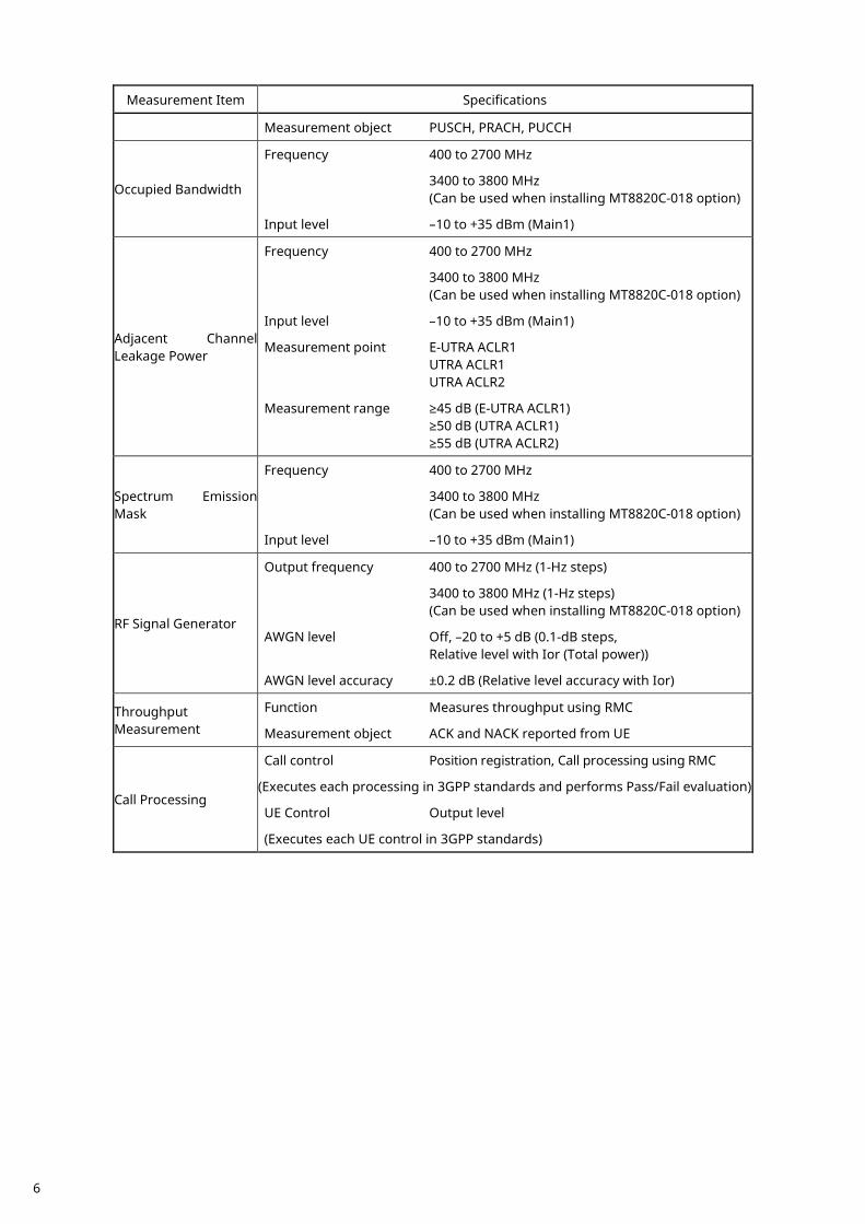
Measurement Item Specifications
Measurement object PUSCH, PRACH, PUCCH
Occupied Bandwidth
Frequency 400 to 2700 MHz
3400 to 3800 MHz (Can be used when installing MT8820C-018 option)
Input level –10 to +35 dBm (Main1)
Adjacent Channel Leakage Power
Frequency 400 to 2700 MHz
3400 to 3800 MHz (Can be used when installing MT8820C-018 option)
Input level –10 to +35 dBm (Main1)
Measurement point E-UTRA ACLR1 UTRA ACLR1 UTRA ACLR2
Measurement range ≥45 dB (E-UTRA ACLR1) ≥50 dB (UTRA ACLR1) ≥55 dB (UTRA ACLR2)
Spectrum Emission Mask
Frequency 400 to 2700 MHz
3400 to 3800 MHz (Can be used when installing MT8820C-018 option)
Input level –10 to +35 dBm (Main1)
RF Signal Generator
Output frequency 400 to 2700 MHz (1-Hz steps)
3400 to 3800 MHz (1-Hz steps) (Can be used when installing MT8820C-018 option)
AWGN level Off, –20 to +5 dB (0.1-dB steps, Relative level with Ior (Total power))
AWGN level accuracy ±0.2 dB (Relative level accuracy with Ior)
Throughput Measurement
Function Measures throughput using RMC
Measurement object ACK and NACK reported from UE
Call Processing
Call control Position registration, Call processing using RMC
(Executes each processing in 3GPP standards and performs Pass/Fail evaluation)
UE Control Output level
(Executes each UE control in 3GPP standards)
6
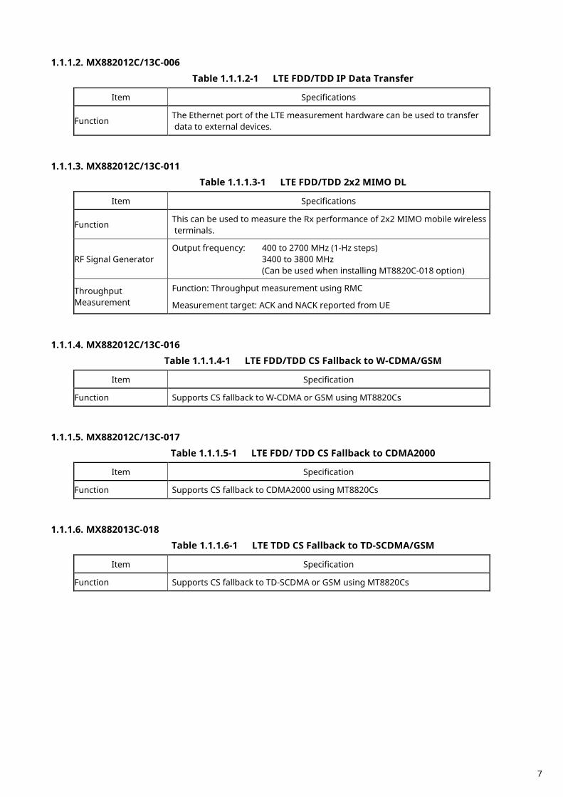
1.1.1.2. MX882012C/13C-006 Table 1.1.1.2-1 LTE FDD/TDD IP Data Transfer
Item Specifications
Function The Ethernet port of the LTE measurement hardware can be used to transfer data to external devices.
1.1.1.3. MX882012C/13C-011
Table 1.1.1.3-1 LTE FDD/TDD 2x2 MIMO DL
Item Specifications
Function This can be used to measure the Rx performance of 2x2 MIMO mobile wireless terminals.
RF Signal Generator Output frequency: 400 to 2700 MHz (1-Hz steps)
3400 to 3800 MHz (Can be used when installing MT8820C-018 option)
Throughput Measurement
Function: Throughput measurement using RMC
Measurement target: ACK and NACK reported from UE
1.1.1.4. MX882012C/13C-016
Table 1.1.1.4-1 LTE FDD/TDD CS Fallback to W-CDMA/GSM
Item Specification
Function Supports CS fallback to W-CDMA or GSM using MT8820Cs
1.1.1.5. MX882012C/13C-017
Table 1.1.1.5-1 LTE FDD/ TDD CS Fallback to CDMA2000
Item Specification
Function Supports CS fallback to CDMA2000 using MT8820Cs
1.1.1.6. MX882013C-018
Table 1.1.1.6-1 LTE TDD CS Fallback to TD-SCDMA/GSM
Item Specification
Function Supports CS fallback to TD-SCDMA or GSM using MT8820Cs
7
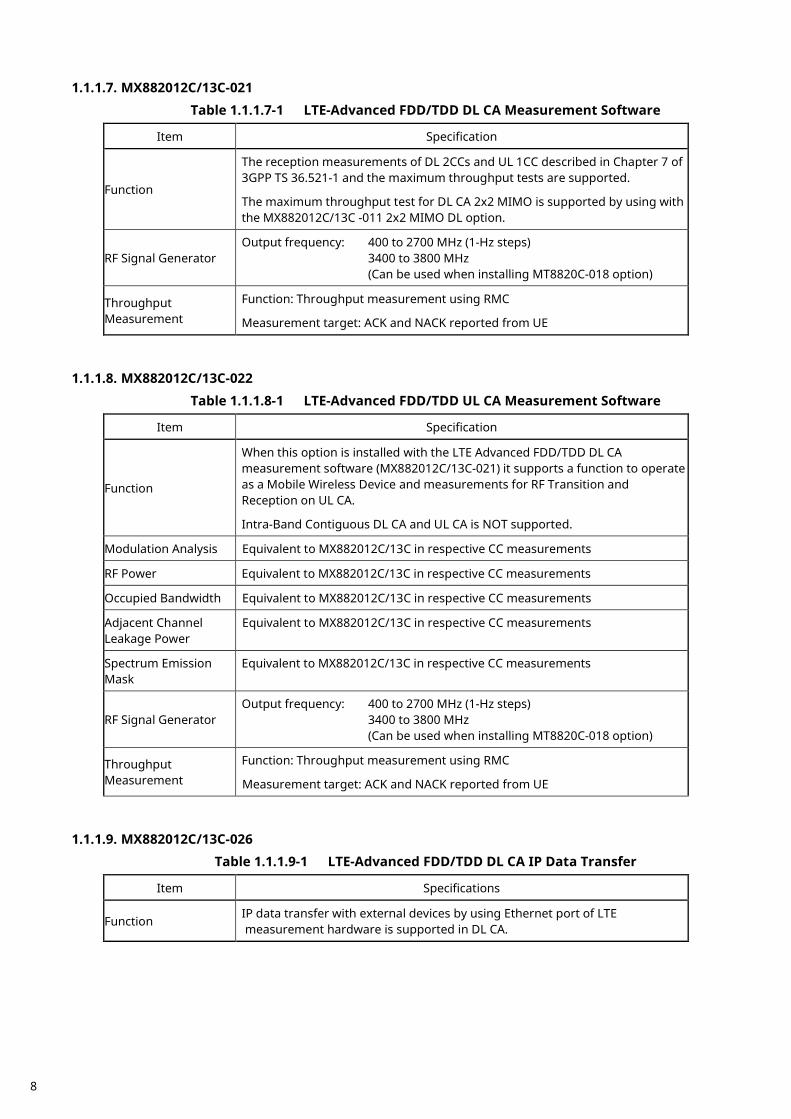
1.1.1.7. MX882012C/13C-021 Table 1.1.1.7-1 LTE-Advanced FDD/TDD DL CA Measurement Software
Item Specification
Function
The reception measurements of DL 2CCs and UL 1CC described in Chapter 7 of 3GPP TS 36.521-1 and the maximum throughput tests are supported.
The maximum throughput test for DL CA 2x2 MIMO is supported by using with the MX882012C/13C -011 2x2 MIMO DL option.
RF Signal Generator Output frequency: 400 to 2700 MHz (1-Hz steps)
3400 to 3800 MHz (Can be used when installing MT8820C-018 option)
Throughput Measurement
Function: Throughput measurement using RMC
Measurement target: ACK and NACK reported from UE
1.1.1.8. MX882012C/13C-022
Table 1.1.1.8-1 LTE-Advanced FDD/TDD UL CA Measurement Software
Item Specification
Function
When this option is installed with the LTE Advanced FDD/TDD DL CA measurement software (MX882012C/13C-021) it supports a function to operate as a Mobile Wireless Device and measurements for RF Transition and Reception on UL CA.
Intra-Band Contiguous DL CA and UL CA is NOT supported.
Modulation Analysis Equivalent to MX882012C/13C in respective CC measurements
RF Power Equivalent to MX882012C/13C in respective CC measurements
Occupied Bandwidth Equivalent to MX882012C/13C in respective CC measurements
Adjacent Channel Leakage Power
Equivalent to MX882012C/13C in respective CC measurements
Spectrum Emission Mask
Equivalent to MX882012C/13C in respective CC measurements
RF Signal Generator Output frequency: 400 to 2700 MHz (1-Hz steps)
3400 to 3800 MHz (Can be used when installing MT8820C-018 option)
Throughput Measurement
Function: Throughput measurement using RMC
Measurement target: ACK and NACK reported from UE
1.1.1.9. MX882012C/13C-026
Table 1.1.1.9-1 LTE-Advanced FDD/TDD DL CA IP Data Transfer
Item Specifications
Function IP data transfer with external devices by using Ethernet port of LTE measurement hardware is supported in DL CA.
8
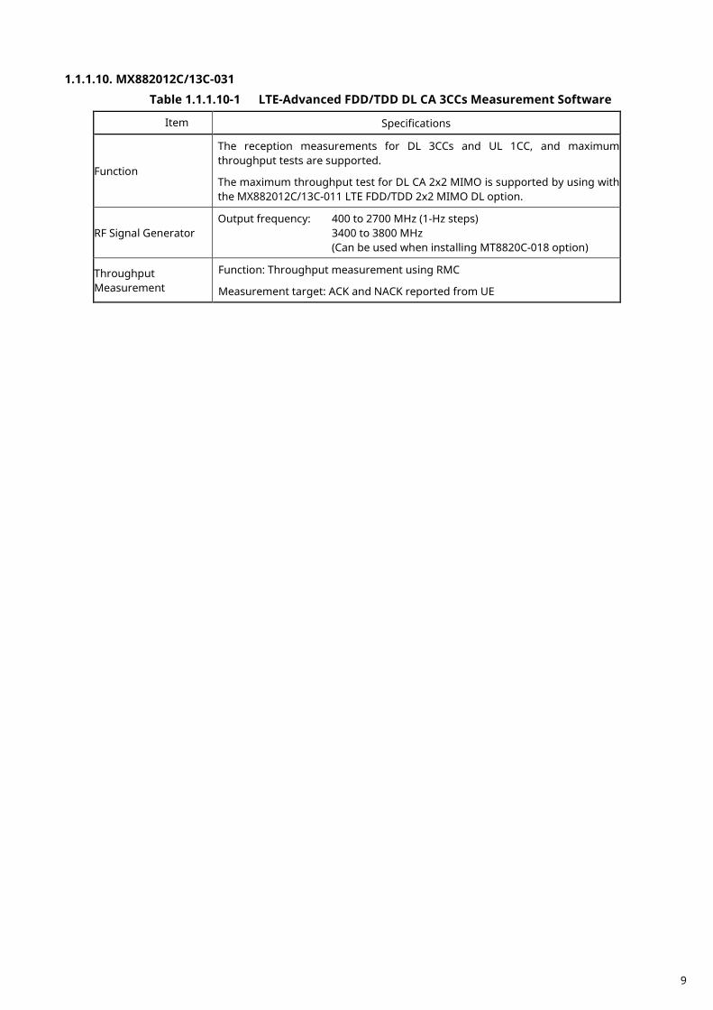
1.1.1.10. MX882012C/13C-031 Table 1.1.1.10-1 LTE-Advanced FDD/TDD DL CA 3CCs Measurement Software
Item Specifications
Function
The reception measurements for DL 3CCs and UL 1CC, and maximum throughput tests are supported.
The maximum throughput test for DL CA 2x2 MIMO is supported by using with the MX882012C/13C-011 LTE FDD/TDD 2x2 MIMO DL option.
RF Signal Generator Output frequency: 400 to 2700 MHz (1-Hz steps)
3400 to 3800 MHz (Can be used when installing MT8820C-018 option)
Throughput Measurement
Function: Throughput measurement using RMC
Measurement target: ACK and NACK reported from UE
9
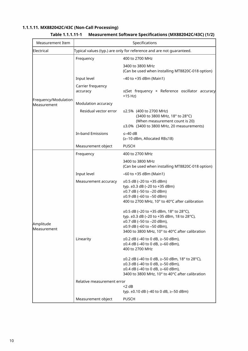
1.1.1.11. MX882042C/43C (Non-Call Processing) Table 1.1.1.11-1 Measurement Software Specifications (MX882042C/43C) (1/2)
Measurement Item Specifications
Electrical Typical values (typ.) are only for reference and are not guaranteed.
Frequency/Modulation Measurement
Frequency 400 to 2700 MHz
3400 to 3800 MHz (Can be used when installing MT8820C-018 option)
Input level –40 to +35 dBm (Main1)
Carrier frequency accuracy ±(Set frequency × Reference oscillator accuracy +15 Hz)
Modulation accuracy
Residual vector error ≤2.5% (400 to 2700 MHz) (3400 to 3800 MHz, 18° to 28°C) (When measurement count is 20) ≤3.0% (3400 to 3800 MHz, 20 measurements)
In-band Emissions ≤–40 dB (≥–10 dBm, Allocated RB≤18)
Measurement object PUSCH
Amplitude Measurement
Frequency 400 to 2700 MHz
3400 to 3800 MHz (Can be used when installing MT8820C-018 option)
Input level –60 to +35 dBm (Main1)
Measurement accuracy ±0.5 dB (–20 to +35 dBm) typ. ±0.3 dB (–20 to +35 dBm) ±0.7 dB (–50 to –20 dBm) ±0.9 dB (–60 to –50 dBm) 400 to 2700 MHz, 10° to 40°C after calibration ±0.5 dB (–20 to +35 dBm, 18° to 28°C), typ. ±0.3 dB (–20 to +35 dBm, 18 to 28°C), ±0.7 dB (–50 to –20 dBm), ±0.9 dB (–60 to –50 dBm), 3400 to 3800 MHz, 10° to 40°C after calibration
Linearity ±0.2 dB (–40 to 0 dB, ≥–50 dBm), ±0.4 dB (–40 to 0 dB, ≥–60 dBm), 400 to 2700 MHz ±0.2 dB (–40 to 0 dB, ≥–50 dBm, 18° to 28°C), ±0.3 dB (–40 to 0 dB, ≥–50 dBm), ±0.4 dB (–40 to 0 dB, ≥–60 dBm), 3400 to 3800 MHz, 10° to 40°C after calibration
Relative measurement error <2 dB typ. ±0.10 dB (–40 to 0 dB, ≥–50 dBm)
Measurement object PUSCH
10
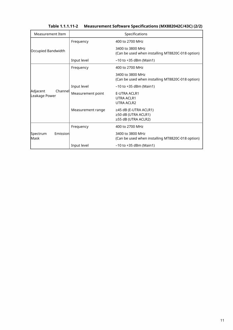
Table 1.1.1.11-2 Measurement Software Specifications (MX882042C/43C) (2/2)
Measurement Item Specifications
Occupied Bandwidth
Frequency 400 to 2700 MHz
3400 to 3800 MHz (Can be used when installing MT8820C-018 option)
Input level –10 to +35 dBm (Main1)
Adjacent Channel Leakage Power
Frequency 400 to 2700 MHz
3400 to 3800 MHz (Can be used when installing MT8820C-018 option)
Input level –10 to +35 dBm (Main1)
Measurement point E-UTRA ACLR1 UTRA ACLR1 UTRA ACLR2
Measurement range ≥45 dB (E-UTRA ACLR1) ≥50 dB (UTRA ACLR1) ≥55 dB (UTRA ACLR2)
Spectrum Emission Mask
Frequency 400 to 2700 MHz
3400 to 3800 MHz (Can be used when installing MT8820C-018 option)
Input level –10 to +35 dBm (Main1)
11
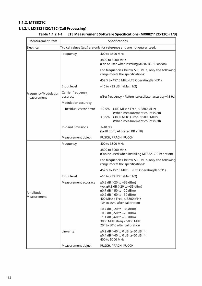
MT8821C 1.1.2.1.1.2.1. MX882112C/13C (Call Processing)
Table 1.1.2.1-1 LTE Measurement Software Specifications (MX882112C/13C) (1/3)
Measurement Item Specifications
Electrical Typical values (typ.) are only for reference and are not guaranteed.
Frequency/Modulation measurement
Frequency 400 to 3800 MHz
3800 to 5000 MHz (Can be used when installing MT8821C-019 option)
For frequencies below 500 MHz, only the following range meets the specifications:
452.5 to 457.5 MHz (LTE OperatingBand31)
Input level –40 to +35 dBm (Main1/2)
Carrier frequency accuracy ±(Set frequency × Reference oscillator accuracy +15 Hz)
Modulation accuracy
Residual vector error ≤ 2.5% (400 MHz ≤ Freq. ≤ 3800 MHz) (When measurement count is 20) ≤ 3.5% (3800 MHz < Freq. ≤ 5000 MHz) (When measurement count is 20)
In-band Emissions ≤–40 dB (≥–10 dBm, Allocated RB ≤ 18)
Measurement object PUSCH, PRACH, PUCCH
Amplitude Measurement
Frequency 400 to 3800 MHz
3800 to 5000 MHz (Can be used when installing MT8821C-019 option)
For frequencies below 500 MHz, only the following range meets the specifications:
452.5 to 457.5 MHz (LTE OperatingBand31)
Input level –60 to +35 dBm (Main1/2)
Measurement accuracy ±0.5 dB (–20 to +35 dBm) typ. ±0.3 dB (–20 to +35 dBm) ±0.7 dB (–50 to –20 dBm) ±0.9 dB (–60 to –50 dBm) 400 MHz ≤ Freq. ≤ 3800 MHz 10° to 40°C after calibration
±0.7 dB (–20 to +35 dBm) ±0.9 dB (–50 to –20 dBm) ±1.1 dB (–60 to –50 dBm) 3800 MHz <freq.≤ 5000 MHz 20° to 30°C after calibration
Linearity ±0.2 dB (–40 to 0 dB, ≥–50 dBm) ±0.4 dB (–40 to 0 dB, ≥–60 dBm) 400 to 5000 MHz
Measurement object PUSCH, PRACH, PUCCH
12
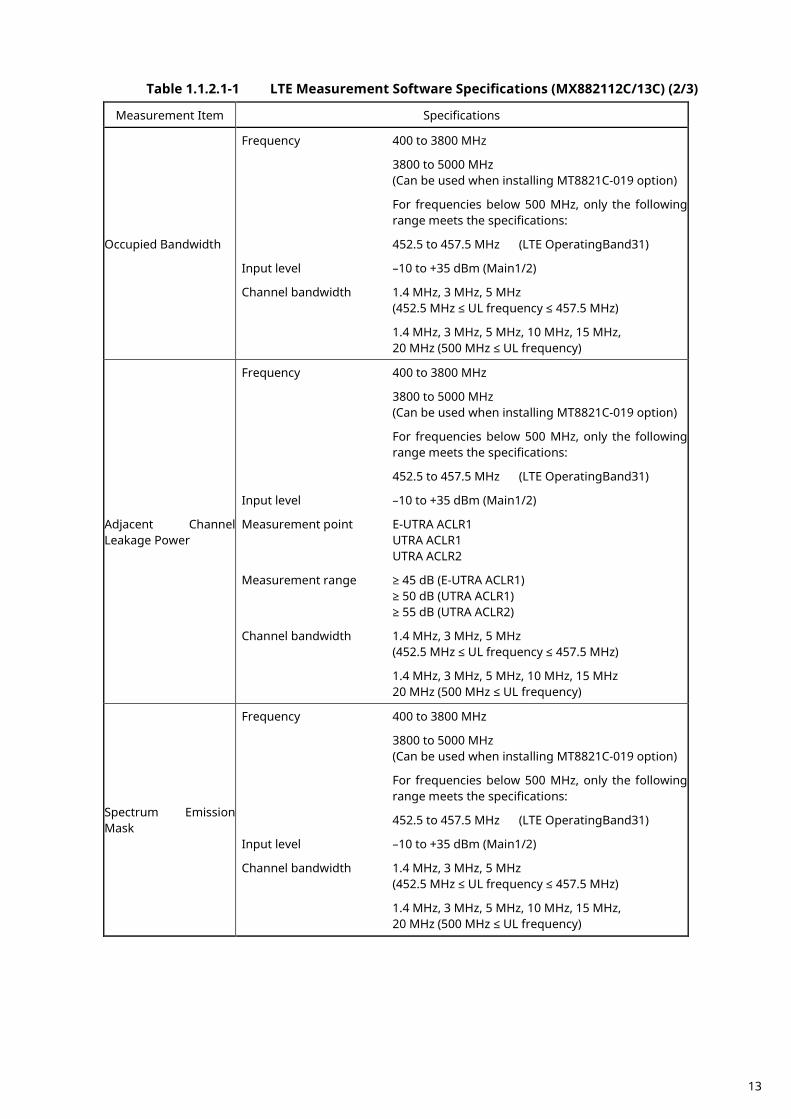
Table 1.1.2.1-1 LTE Measurement Software Specifications (MX882112C/13C) (2/3)
Measurement Item Specifications
Occupied Bandwidth
Frequency 400 to 3800 MHz
3800 to 5000 MHz (Can be used when installing MT8821C-019 option)
For frequencies below 500 MHz, only the following range meets the specifications:
452.5 to 457.5 MHz (LTE OperatingBand31)
Input level –10 to +35 dBm (Main1/2)
Channel bandwidth 1.4 MHz, 3 MHz, 5 MHz (452.5 MHz ≤ UL frequency ≤ 457.5 MHz)
1.4 MHz, 3 MHz, 5 MHz, 10 MHz, 15 MHz, 20 MHz (500 MHz ≤ UL frequency)
Adjacent Channel Leakage Power
Frequency 400 to 3800 MHz
3800 to 5000 MHz (Can be used when installing MT8821C-019 option)
For frequencies below 500 MHz, only the following range meets the specifications:
452.5 to 457.5 MHz (LTE OperatingBand31)
Input level –10 to +35 dBm (Main1/2)
Measurement point E-UTRA ACLR1 UTRA ACLR1 UTRA ACLR2
Measurement range ≥ 45 dB (E-UTRA ACLR1) ≥ 50 dB (UTRA ACLR1) ≥ 55 dB (UTRA ACLR2)
Channel bandwidth 1.4 MHz, 3 MHz, 5 MHz (452.5 MHz ≤ UL frequency ≤ 457.5 MHz)
1.4 MHz, 3 MHz, 5 MHz, 10 MHz, 15 MHz 20 MHz (500 MHz ≤ UL frequency)
Spectrum Emission Mask
Frequency 400 to 3800 MHz
3800 to 5000 MHz (Can be used when installing MT8821C-019 option)
For frequencies below 500 MHz, only the following range meets the specifications:
452.5 to 457.5 MHz (LTE OperatingBand31)
Input level –10 to +35 dBm (Main1/2)
Channel bandwidth 1.4 MHz, 3 MHz, 5 MHz (452.5 MHz ≤ UL frequency ≤ 457.5 MHz)
1.4 MHz, 3 MHz, 5 MHz, 10 MHz, 15 MHz, 20 MHz (500 MHz ≤ UL frequency)
13
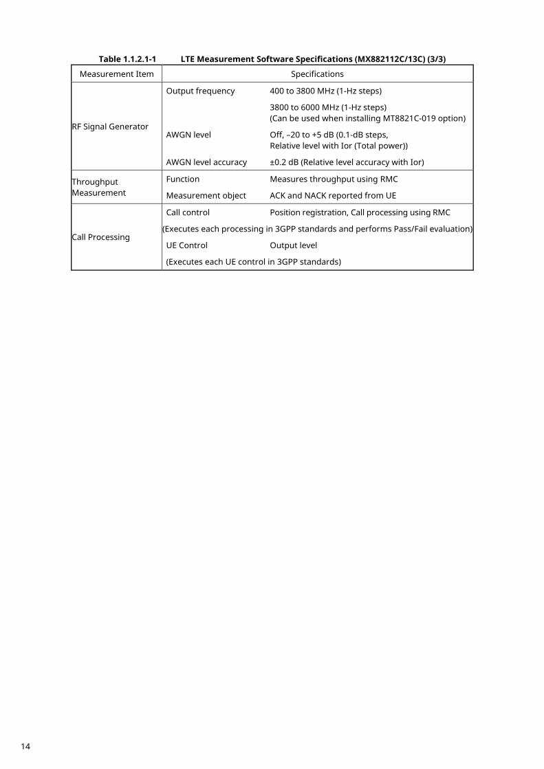
Table 1.1.2.1-1 LTE Measurement Software Specifications (MX882112C/13C) (3/3)
Measurement Item Specifications
RF Signal Generator
Output frequency 400 to 3800 MHz (1-Hz steps)
3800 to 6000 MHz (1-Hz steps) (Can be used when installing MT8821C-019 option)
AWGN level Off, –20 to +5 dB (0.1-dB steps, Relative level with Ior (Total power))
AWGN level accuracy ±0.2 dB (Relative level accuracy with Ior)
Throughput Measurement
Function Measures throughput using RMC
Measurement object ACK and NACK reported from UE
Call Processing
Call control Position registration, Call processing using RMC
(Executes each processing in 3GPP standards and performs Pass/Fail evaluation)
UE Control Output level
(Executes each UE control in 3GPP standards)
14
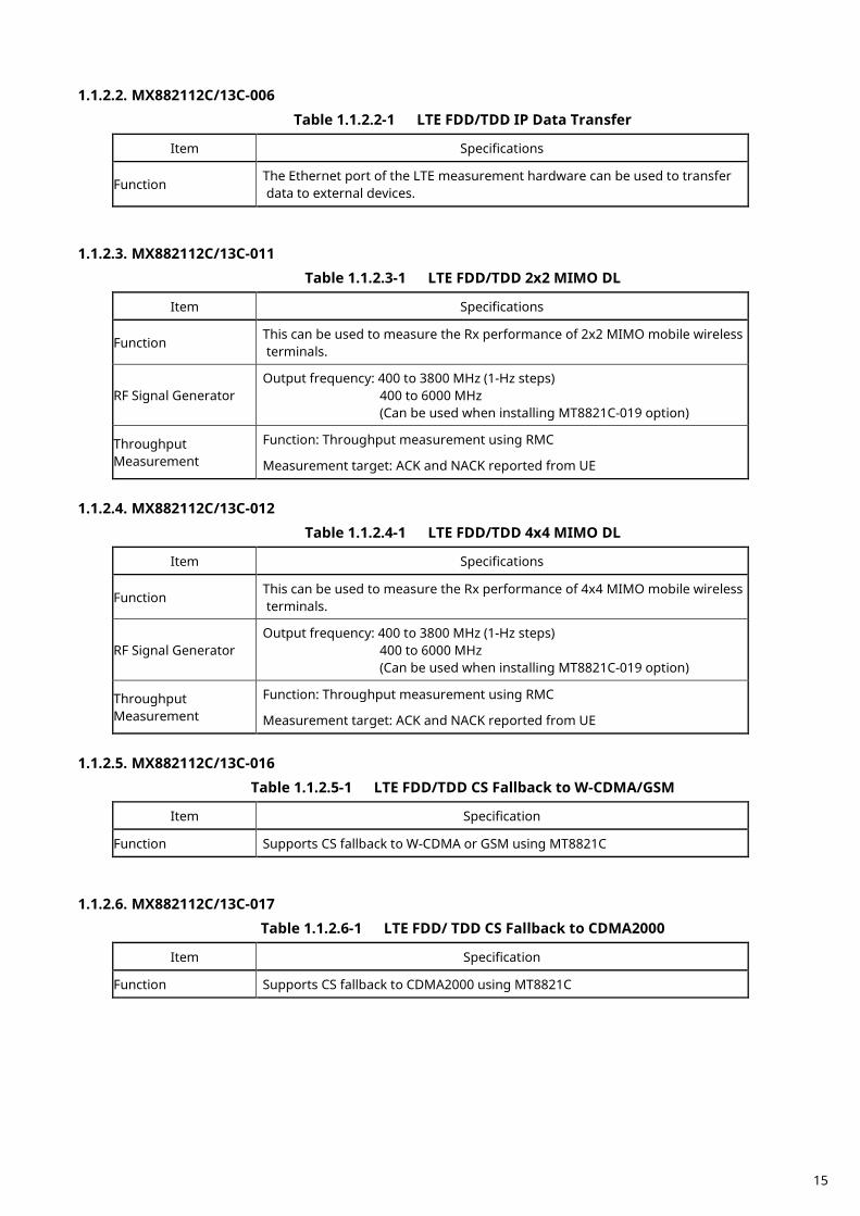
1.1.2.2. MX882112C/13C-006 Table 1.1.2.2-1 LTE FDD/TDD IP Data Transfer
Item Specifications
Function The Ethernet port of the LTE measurement hardware can be used to transfer data to external devices.
1.1.2.3. MX882112C/13C-011
Table 1.1.2.3-1 LTE FDD/TDD 2x2 MIMO DL
Item Specifications
Function This can be used to measure the Rx performance of 2x2 MIMO mobile wireless terminals.
RF Signal Generator Output frequency: 400 to 3800 MHz (1-Hz steps)
400 to 6000 MHz (Can be used when installing MT8821C-019 option)
Throughput Measurement
Function: Throughput measurement using RMC
Measurement target: ACK and NACK reported from UE
1.1.2.4. MX882112C/13C-012
Table 1.1.2.4-1 LTE FDD/TDD 4x4 MIMO DL
Item Specifications
Function This can be used to measure the Rx performance of 4x4 MIMO mobile wireless terminals.
RF Signal Generator Output frequency: 400 to 3800 MHz (1-Hz steps)
400 to 6000 MHz (Can be used when installing MT8821C-019 option)
Throughput Measurement
Function: Throughput measurement using RMC
Measurement target: ACK and NACK reported from UE
1.1.2.5. MX882112C/13C-016
Table 1.1.2.5-1 LTE FDD/TDD CS Fallback to W-CDMA/GSM
Item Specification
Function Supports CS fallback to W-CDMA or GSM using MT8821C
1.1.2.6. MX882112C/13C-017
Table 1.1.2.6-1 LTE FDD/ TDD CS Fallback to CDMA2000
Item Specification
Function Supports CS fallback to CDMA2000 using MT8821C
15

1.1.2.7. MX882113C-018
Table 1.1.2.7-1 LTE TDD CS Fallback to TD-SCDMA/GSM
Item Specification
Function Supports CS fallback to TD-SCDMA or GSM using MT8821C
1.1.2.8. MX882112C/13C-021
Table 1.1.2.8-1 LTE-Advanced FDD/TDD DL CA Measurement Software
Item Specification
Function
The reception measurements for DL 2CCs and UL 1CC described in Chapter 7 of 3GPP TS 36.521-1 and the maximum throughput tests are supported.
The maximum throughput test for DL CA 2x2 MIMO is supported by using with the MX882012C/13C -011 2x2 MIMO DL option.
RF Signal Generator Output frequency: 400 to 2700 MHz (1-Hz steps)
3400 to 3800 MHz (Can be used when installing MT8821C-018 option)
Throughput Measurement
Function: Throughput measurement using RMC
Measurement target: ACK and NACK reported from UE
1.1.2.9. MX882112C/13C-022
Table 1.1.2.9-1 LTE-Advanced FDD/TDD UL CA Measurement Software
Item Specification
Function
This can be used to measure the functions and Tx/Rx performance of UEs at 2CCs UL CA.
Frequency 500 to 3800 MHz 3800 to 4200 MHz (Can be used when installing MT8821C-019 option)
Modulation Analysis Same as MX882112C for CC measurements. The measurement target is only PUSCH.
16
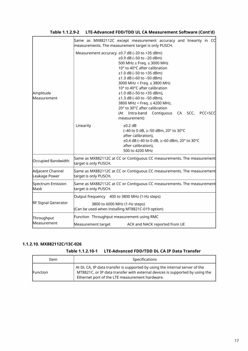
Table 1.1.2.9-2 LTE-Advanced FDD/TDD UL CA Measurement Software (Cont’d)
Amplitude Measurement
Same as MX882112C except measurement accuracy and linearity in CC measurements. The measurement target is only PUSCH.
Measurement accuracy ±0.7 dB (–20 to +35 dBm) ±0.9 dB (–50 to –20 dBm) 500 MHz ≤ Freq. ≤ 3000 MHz 10° to 40°C after calibration ±1.0 dB (–50 to +35 dBm) ±1.3 dB (–60 to –50 dBm) 3000 MHz < Freq. ≤ 3800 MHz 10° to 40°C after calibration ±1.0 dB (–50 to +35 dBm), ±1.3 dB (–60 to –50 dBm), 3800 MHz < Freq. ≤ 4200 MHz, 20° to 30°C after calibration (At Intra-band Contiguous CA SCC, PCC+SCC measurement)
Linearity ±0.2 dB (–40 to 0 dB, ≥–50 dBm, 20° to 30°C after calibration), ±0.4 dB (–40 to 0 dB, ≥–60 dBm, 20° to 30°C after calibration), 500 to 4200 MHz
Occupied Bandwidth Same as MX882112C at CC or Contiguous CC measurements. The measurement target is only PUSCH.
Adjacent Channel Leakage Power
Same as MX882112C at CC or Contiguous CC measurements. The measurement target is only PUSCH.
Spectrum Emission Mask
Same as MX882112C at CC or Contiguous CC measurements. The measurement target is only PUSCH.
RF Signal Generator
Output frequency 400 to 3800 MHz (1-Hz steps)
3800 to 6000 MHz (1-Hz steps) (Can be used when installing MT8821C-019 option)
Throughput Measurement
Function Throughput measurement using RMC
Measurement target ACK and NACK reported from UE
1.1.2.10. MX882112C/13C-026
Table 1.1.2.10-1 LTE-Advanced FDD/TDD DL CA IP Data Transfer
Item Specifications
Function At DL CA, IP data transfer is supported by using the internal server of the MT8821C, or IP data transfer with external devices is supported by using the Ethernet port of the LTE measurement hardware.
17
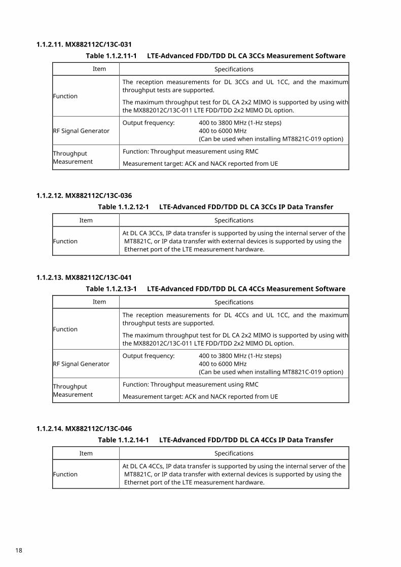
1.1.2.11. MX882112C/13C-031 Table 1.1.2.11-1 LTE-Advanced FDD/TDD DL CA 3CCs Measurement Software
Item Specifications
Function
The reception measurements for DL 3CCs and UL 1CC, and the maximum throughput tests are supported.
The maximum throughput test for DL CA 2x2 MIMO is supported by using with the MX882012C/13C-011 LTE FDD/TDD 2x2 MIMO DL option.
RF Signal Generator Output frequency: 400 to 3800 MHz (1-Hz steps)
400 to 6000 MHz (Can be used when installing MT8821C-019 option)
Throughput Measurement
Function: Throughput measurement using RMC
Measurement target: ACK and NACK reported from UE
1.1.2.12. MX882112C/13C-036
Table 1.1.2.12-1 LTE-Advanced FDD/TDD DL CA 3CCs IP Data Transfer
Item Specifications
Function At DL CA 3CCs, IP data transfer is supported by using the internal server of the MT8821C, or IP data transfer with external devices is supported by using the Ethernet port of the LTE measurement hardware.
1.1.2.13. MX882112C/13C-041
Table 1.1.2.13-1 LTE-Advanced FDD/TDD DL CA 4CCs Measurement Software
Item Specifications
Function
The reception measurements for DL 4CCs and UL 1CC, and the maximum throughput tests are supported.
The maximum throughput test for DL CA 2x2 MIMO is supported by using with the MX882012C/13C-011 LTE FDD/TDD 2x2 MIMO DL option.
RF Signal Generator Output frequency: 400 to 3800 MHz (1-Hz steps)
400 to 6000 MHz (Can be used when installing MT8821C-019 option)
Throughput Measurement
Function: Throughput measurement using RMC
Measurement target: ACK and NACK reported from UE
1.1.2.14. MX882112C/13C-046
Table 1.1.2.14-1 LTE-Advanced FDD/TDD DL CA 4CCs IP Data Transfer
Item Specifications
Function At DL CA 4CCs, IP data transfer is supported by using the internal server of the MT8821C, or IP data transfer with external devices is supported by using the Ethernet port of the LTE measurement hardware.
18
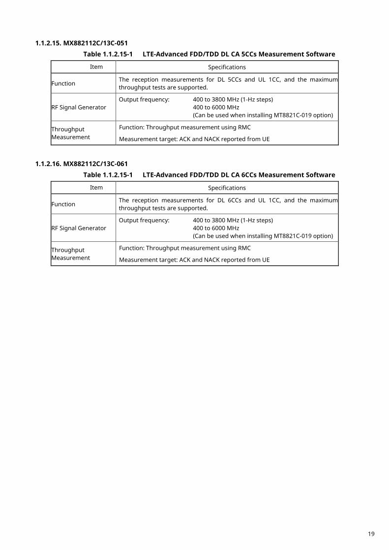
1.1.2.15. MX882112C/13C-051 Table 1.1.2.15-1 LTE-Advanced FDD/TDD DL CA 5CCs Measurement Software
Item Specifications
Function The reception measurements for DL 5CCs and UL 1CC, and the maximum throughput tests are supported.
RF Signal Generator Output frequency: 400 to 3800 MHz (1-Hz steps)
400 to 6000 MHz (Can be used when installing MT8821C-019 option)
Throughput Measurement
Function: Throughput measurement using RMC
Measurement target: ACK and NACK reported from UE 1.1.2.16. MX882112C/13C-061
Table 1.1.2.15-1 LTE-Advanced FDD/TDD DL CA 6CCs Measurement Software
Item Specifications
Function The reception measurements for DL 6CCs and UL 1CC, and the maximum throughput tests are supported.
RF Signal Generator Output frequency: 400 to 3800 MHz (1-Hz steps)
400 to 6000 MHz (Can be used when installing MT8821C-019 option)
Throughput Measurement
Function: Throughput measurement using RMC
Measurement target: ACK and NACK reported from UE
19
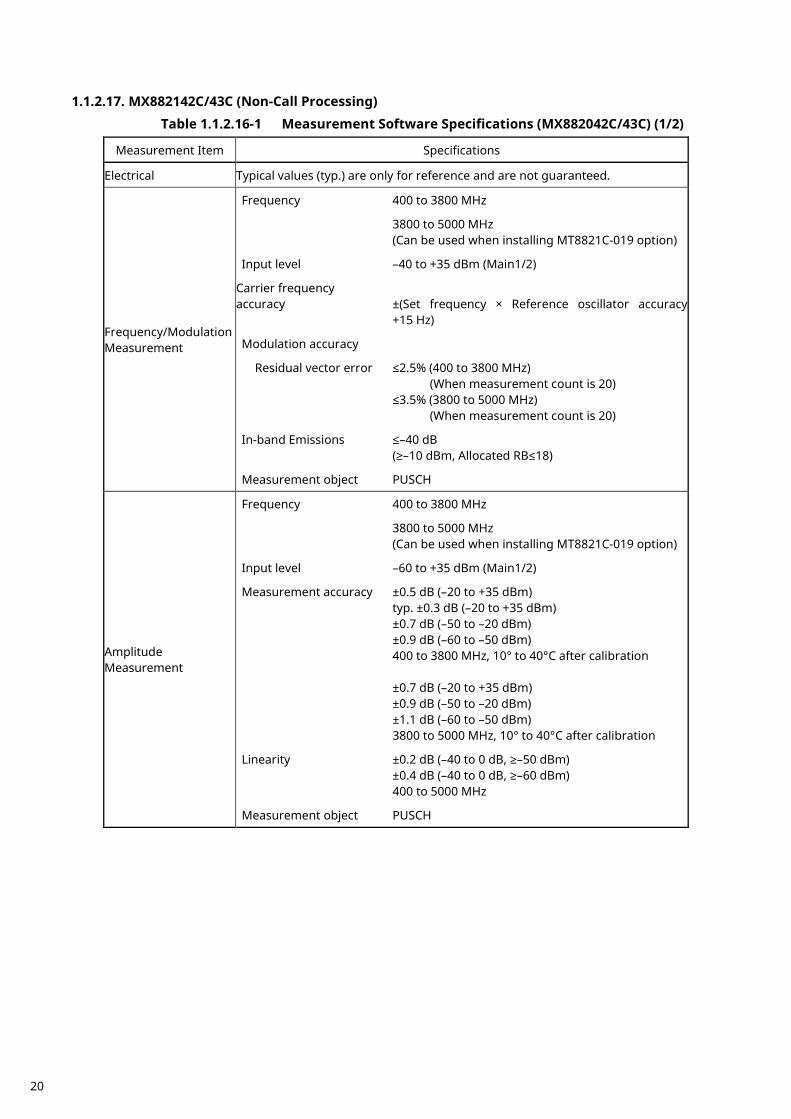
1.1.2.17. MX882142C/43C (Non-Call Processing)
Table 1.1.2.16-1 Measurement Software Specifications (MX882042C/43C) (1/2)
Measurement Item Specifications
Electrical Typical values (typ.) are only for reference and are not guaranteed.
Frequency/Modulation Measurement
Frequency 400 to 3800 MHz
3800 to 5000 MHz (Can be used when installing MT8821C-019 option)
Input level –40 to +35 dBm (Main1/2)
Carrier frequency accuracy ±(Set frequency × Reference oscillator accuracy +15 Hz)
Modulation accuracy
Residual vector error ≤2.5% (400 to 3800 MHz) (When measurement count is 20) ≤3.5% (3800 to 5000 MHz) (When measurement count is 20)
In-band Emissions ≤–40 dB (≥–10 dBm, Allocated RB≤18)
Measurement object PUSCH
Amplitude Measurement
Frequency 400 to 3800 MHz
3800 to 5000 MHz (Can be used when installing MT8821C-019 option)
Input level –60 to +35 dBm (Main1/2)
Measurement accuracy ±0.5 dB (–20 to +35 dBm) typ. ±0.3 dB (–20 to +35 dBm) ±0.7 dB (–50 to –20 dBm) ±0.9 dB (–60 to –50 dBm) 400 to 3800 MHz, 10° to 40°C after calibration ±0.7 dB (–20 to +35 dBm) ±0.9 dB (–50 to –20 dBm) ±1.1 dB (–60 to –50 dBm) 3800 to 5000 MHz, 10° to 40°C after calibration
Linearity ±0.2 dB (–40 to 0 dB, ≥–50 dBm) ±0.4 dB (–40 to 0 dB, ≥–60 dBm) 400 to 5000 MHz
Measurement object PUSCH
20
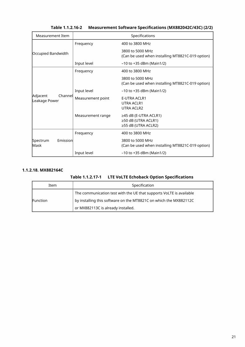
Table 1.1.2.16-2 Measurement Software Specifications (MX882042C/43C) (2/2)
Measurement Item Specifications
Occupied Bandwidth
Frequency 400 to 3800 MHz
3800 to 5000 MHz (Can be used when installing MT8821C-019 option)
Input level –10 to +35 dBm (Main1/2)
Adjacent Channel Leakage Power
Frequency 400 to 3800 MHz
3800 to 5000 MHz (Can be used when installing MT8821C-019 option)
Input level –10 to +35 dBm (Main1/2)
Measurement point E-UTRA ACLR1 UTRA ACLR1 UTRA ACLR2
Measurement range ≥45 dB (E-UTRA ACLR1) ≥50 dB (UTRA ACLR1) ≥55 dB (UTRA ACLR2)
Spectrum Emission Mask
Frequency 400 to 3800 MHz
3800 to 5000 MHz (Can be used when installing MT8821C-019 option)
Input level –10 to +35 dBm (Main1/2)
1.1.2.18. MX882164C
Table 1.1.2.17-1 LTE VoLTE Echoback Option Specifications
Item Specification
Function
The communication test with the UE that supports VoLTE is available
by installing this software on the MT8821C on which the MX882112C
or MX882113C is already installed.
21
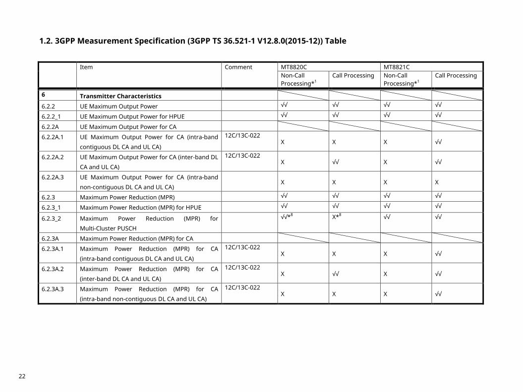
3GPP Measurement Specification (3GPP TS 36.521-1 V12.8.0(2015-12)) Table 1.2.
Item Comment MT8820C MT8821C Non-Call Processing*1
Call Processing Non-Call Processing*1
Call Processing
6 Transmitter Characteristics
6.2.2 UE Maximum Output Power √√ √√ √√ √√
6.2.2_1 UE Maximum Output Power for HPUE √√ √√ √√ √√
6.2.2A UE Maximum Output Power for CA
6.2.2A.1 UE Maximum Output Power for CA (intra-band
contiguous DL CA and UL CA)
12C/13C-022 X X X √√
6.2.2A.2 UE Maximum Output Power for CA (inter-band DL
CA and UL CA)
12C/13C-022 X √√ X √√
6.2.2A.3 UE Maximum Output Power for CA (intra-band
non-contiguous DL CA and UL CA)
X X X X
6.2.3 Maximum Power Reduction (MPR) √√ √√ √√ √√
6.2.3_1 Maximum Power Reduction (MPR) for HPUE √√ √√ √√ √√
6.2.3_2 Maximum Power Reduction (MPR) for
Multi-Cluster PUSCH
√√*8 X*8 √√ √√
6.2.3A Maximum Power Reduction (MPR) for CA
6.2.3A.1 Maximum Power Reduction (MPR) for CA
(intra-band contiguous DL CA and UL CA)
12C/13C-022 X X X √√
6.2.3A.2 Maximum Power Reduction (MPR) for CA
(inter-band DL CA and UL CA)
12C/13C-022 X √√ X √√
6.2.3A.3 Maximum Power Reduction (MPR) for CA
(intra-band non-contiguous DL CA and UL CA)
12C/13C-022 X X X √√
22
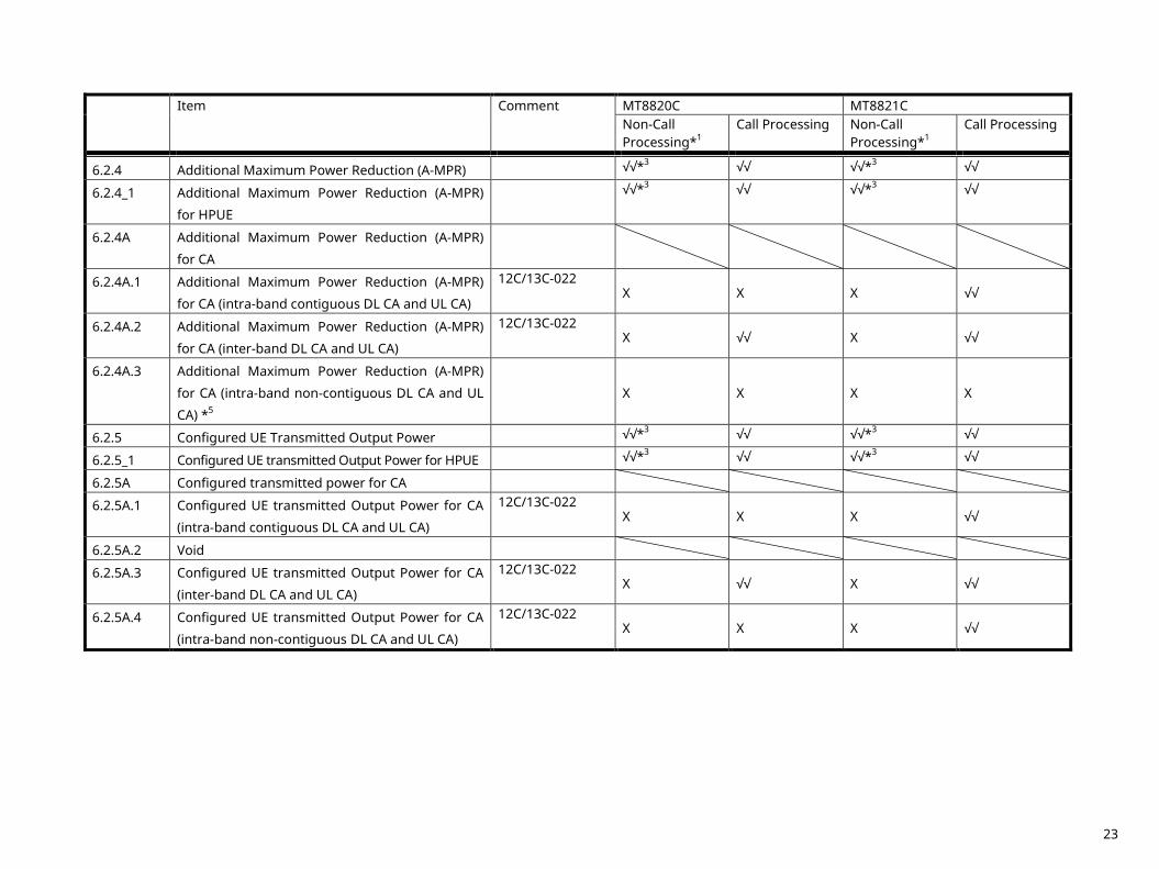
Item Comment MT8820C MT8821C
Non-Call Processing*1
Call Processing Non-Call Processing*1
Call Processing
6.2.4 Additional Maximum Power Reduction (A-MPR) √√*3 √√ √√*3 √√
6.2.4_1 Additional Maximum Power Reduction (A-MPR)
for HPUE
√√*3 √√ √√*3 √√
6.2.4A Additional Maximum Power Reduction (A-MPR)
for CA
6.2.4A.1 Additional Maximum Power Reduction (A-MPR)
for CA (intra-band contiguous DL CA and UL CA)
12C/13C-022 X X X √√
6.2.4A.2 Additional Maximum Power Reduction (A-MPR)
for CA (inter-band DL CA and UL CA)
12C/13C-022 X √√ X √√
6.2.4A.3 Additional Maximum Power Reduction (A-MPR)
for CA (intra-band non-contiguous DL CA and UL
CA) *5
X X X X
6.2.5 Configured UE Transmitted Output Power √√*3 √√ √√*3 √√
6.2.5_1 Configured UE transmitted Output Power for HPUE √√*3 √√ √√*3 √√
6.2.5A Configured transmitted power for CA
6.2.5A.1 Configured UE transmitted Output Power for CA
(intra-band contiguous DL CA and UL CA)
12C/13C-022 X X X √√
6.2.5A.2 Void
6.2.5A.3 Configured UE transmitted Output Power for CA
(inter-band DL CA and UL CA)
12C/13C-022 X √√ X √√
6.2.5A.4 Configured UE transmitted Output Power for CA
(intra-band non-contiguous DL CA and UL CA)
12C/13C-022 X X X √√
23

Item Comment MT8820C MT8821C
Non-Call Processing*1
Call Processing Non-Call Processing*1
Call Processing
6.3 Output Power Dynamics
6.3.1 Void
6.3.2 Minimum Output Power √√ √√ √√ √√
6.3.2A Minimum Output Power for CA
6.3.2A.1 Minimum Output Power for CA
(intra-band contiguous DL CA and UL CA)
12C/13C-022 X X √√ √√
6.3.3 Transmit OFF Power X √√ X √√
6.3.3A UE Transmit OFF Power for CA
6.3.3A.1 UE Transmit OFF Power for CA
(intra-band contiguous DL CA and UL CA)
12C/13C-022 X X X √√
6.3.3A.2 UE Transmit OFF power for CA
(inter-band DL CA and UL CA)
12C/13C-022 X √√ X √√
6.3.3A.3 UE Transmit OFF power for CA
(intra-band non-contiguous DL CA and UL CA)
12C/13C-022 X X X √√
6.3.4 ON/OFF Time Mask
6.3.4.1 General ON/OFF time Mask X √√ X √√
6.3.4.2 PRACH and SRS time Mask
6.3.4.2.1 PRACH time Mask X √√ X √√
6.3.4.2.2 SRS time Mask X √√ X √√
6.3.4A ON/OFF time Mask for CA
6.3.4A.1.1 General ON/OFF time Mask for CA
(intra-band contiguous DL CA and UL CA)
12C/13C-022 X X X √√
6.3.4A.1.2 General ON/OFF time mask for CA
(inter-band DL CA and UL CA)
12C/13C-022 X √√ X √√
6.3.4A.1.3 General ON/OFF time mask for CA
(intra-band non-contiguous DL CA and UL CA)
12C/13C-022 X X X √√
24
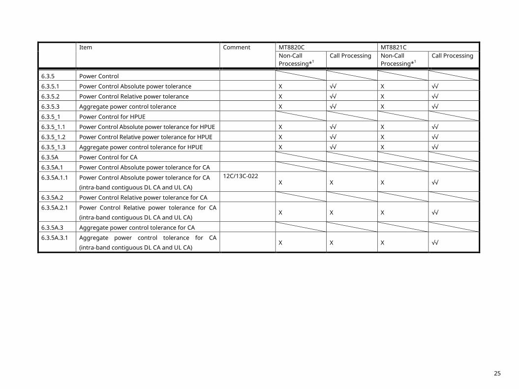
Item Comment MT8820C MT8821C
Non-Call Processing*1
Call Processing Non-Call Processing*1
Call Processing
6.3.5 Power Control
6.3.5.1 Power Control Absolute power tolerance X √√ X √√
6.3.5.2 Power Control Relative power tolerance X √√ X √√
6.3.5.3 Aggregate power control tolerance X √√ X √√
6.3.5_1 Power Control for HPUE
6.3.5_1.1 Power Control Absolute power tolerance for HPUE X √√ X √√
6.3.5_1.2 Power Control Relative power tolerance for HPUE X √√ X √√
6.3.5_1.3 Aggregate power control tolerance for HPUE X √√ X √√
6.3.5A Power Control for CA
6.3.5A.1 Power Control Absolute power tolerance for CA
6.3.5A.1.1 Power Control Absolute power tolerance for CA
(intra-band contiguous DL CA and UL CA)
12C/13C-022 X X X √√
6.3.5A.2 Power Control Relative power tolerance for CA
6.3.5A.2.1 Power Control Relative power tolerance for CA
(intra-band contiguous DL CA and UL CA)
X X X √√
6.3.5A.3 Aggregate power control tolerance for CA
6.3.5A.3.1 Aggregate power control tolerance for CA
(intra-band contiguous DL CA and UL CA)
X X X √√
25
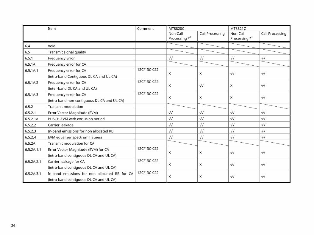
Item Comment MT8820C MT8821C
Non-Call Processing *1
Call Processing Non-Call Processing *1
Call Processing
6.4 Void
6.5 Transmit signal quality
6.5.1 Frequency Error √√ √√ √√ √√
6.5.1A Frequency error for CA
6.5.1A.1 Frequency error for CA
(intra-band Contiguous DL CA and UL CA)
12C/13C-022 X X √√ √√
6.5.1A.2 Frequency error for CA
(inter-band DL CA and UL CA)
12C/13C-022 X √√ X √√
6.5.1A.3 Frequency error for CA
(intra-band non-contiguous DL CA and UL CA)
12C/13C-022 X X X √√
6.5.2 Transmit modulation
6.5.2.1 Error Vector Magnitude (EVM) √√ √√ √√ √√
6.5.2.1A PUSCH-EVM with exclusion period √√ √√ √√ √√
6.5.2.2 Carrier leakage √√ √√ √√ √√
6.5.2.3 In-band emissions for non allocated RB √√ √√ √√ √√
6.5.2.4 EVM equalizer spectrum flatness √√ √√ √√ √√
6.5.2A Transmit modulation for CA
6.5.2A.1.1 Error Vector Magnitude (EVM) for CA
(intra-band contiguous DL CA and UL CA)
12C/13C-022 X X √√ √√
6.5.2A.2.1 Carrier leakage for CA
(intra-band contiguous DL CA and UL CA)
12C/13C-022 X X √√ √√
6.5.2A.3.1 In-band emissions for non allocated RB for CA
(intra-band contiguous DL CA and UL CA)
12C/13C-022 X X √√ √√
26
Item Comment MT8820C MT8821C
Non-Call Processing*1
Call Processing Non-Call Processing*1
Call Processing
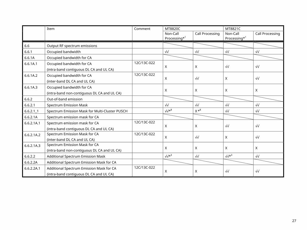
6.6 Output RF spectrum emissions
6.6.1 Occupied bandwidth √√ √√ √√ √√
6.6.1A Occupied bandwidth for CA
6.6.1A.1 Occupied bandwidth for CA
(intra-band contiguous DL CA and UL CA)
12C/13C-022 X X √√ √√
6.6.1A.2 Occupied bandwidth for CA
(inter-band DL CA and UL CA)
12C/13C-022 X √√ X √√
6.6.1A.3 Occupied bandwidth for CA
(intra-band non-contiguous DL CA and UL CA)
X X X X
6.6.2 Out-of-band emission
6.6.2.1 Spectrum Emission Mask √√ √√ √√ √√
6.6.2.1_1 Spectrum Emission Mask for Multi-Cluster PUSCH √√*8 X *8 √√ √√
6.6.2.1A Spectrum emission mask for CA
6.6.2.1A.1 Spectrum emission mask for CA
(intra-band contiguous DL CA and UL CA)
12C/13C-022 X X √√ √√
6.6.2.1A.2 Spectrum Emission Mask for CA (inter-band DL CA and UL CA)
12C/13C-022 X √√ X √√
6.6.2.1A.3 Spectrum Emission Mask for CA (intra-band non-contiguous DL CA and UL CA)
X X X X
6.6.2.2 Additional Spectrum Emission Mask √√*3 √√ √√*3 √√
6.6.2.2A Additional Spectrum Emission Mask for CA
6.6.2.2A.1 Additional Spectrum Emission Mask for CA
(intra-band contiguous DL CA and UL CA)
12C/13C-022 X X √√ √√
27
Item Comment MT8820C MT8821C
Non-Call Processing*1
Call Processing Non-Call Processing*1
Call Processing
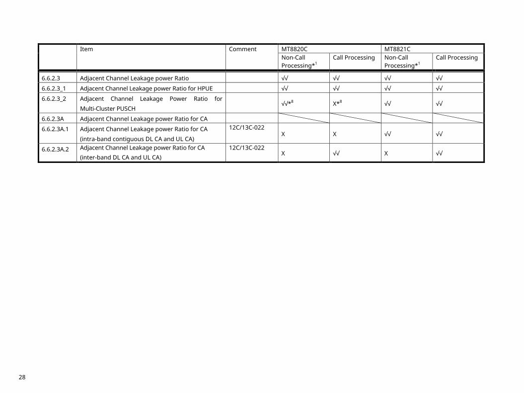
6.6.2.3 Adjacent Channel Leakage power Ratio √√ √√ √√ √√
6.6.2.3_1 Adjacent Channel Leakage power Ratio for HPUE √√ √√ √√ √√
6.6.2.3_2 Adjacent Channel Leakage Power Ratio for
Multi-Cluster PUSCH
√√*8 X*8 √√ √√
6.6.2.3A Adjacent Channel Leakage power Ratio for CA
6.6.2.3A.1 Adjacent Channel Leakage power Ratio for CA
(intra-band contiguous DL CA and UL CA)
12C/13C-022 X X √√ √√
6.6.2.3A.2 Adjacent Channel Leakage power Ratio for CA (inter-band DL CA and UL CA)
12C/13C-022 X √√ X √√
28
Item Comment MT8820C MT8821C
Non-Call Processing*1
Call Processing Non-Call Processing*1
Call Processing
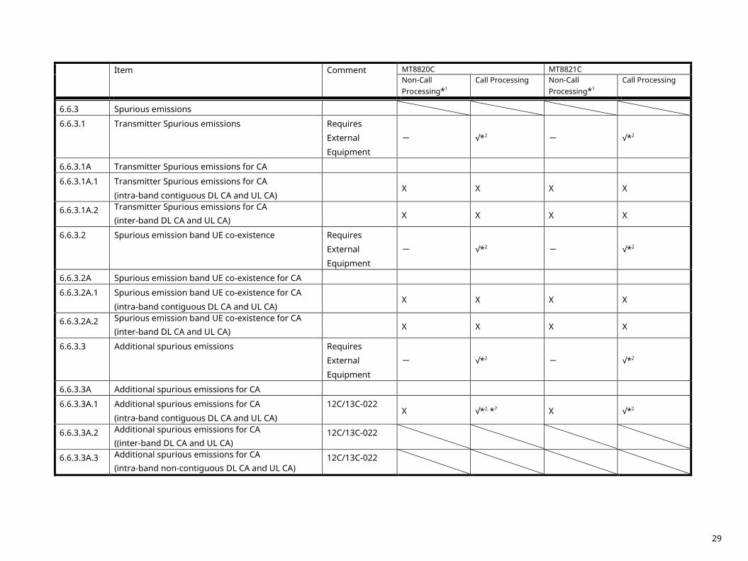
6.6.3 Spurious emissions
6.6.3.1 Transmitter Spurious emissions Requires
External
Equipment
- √*2 - √*2
6.6.3.1A Transmitter Spurious emissions for CA
6.6.3.1A.1 Transmitter Spurious emissions for CA
(intra-band contiguous DL CA and UL CA)
X X X X
6.6.3.1A.2 Transmitter Spurious emissions for CA (inter-band DL CA and UL CA)
X X X X
6.6.3.2 Spurious emission band UE co-existence Requires
External
Equipment
- √*2 - √*2
6.6.3.2A Spurious emission band UE co-existence for CA
6.6.3.2A.1 Spurious emission band UE co-existence for CA
(intra-band contiguous DL CA and UL CA)
X X X X
6.6.3.2A.2 Spurious emission band UE co-existence for CA (inter-band DL CA and UL CA)
X X X X
6.6.3.3 Additional spurious emissions Requires
External
Equipment
- √*2 - √*2
6.6.3.3A Additional spurious emissions for CA
6.6.3.3A.1 Additional spurious emissions for CA
(intra-band contiguous DL CA and UL CA)
12C/13C-022 X √*2, *7 X √*2
6.6.3.3A.2 Additional spurious emissions for CA ((inter-band DL CA and UL CA)
12C/13C-022
6.6.3.3A.3 Additional spurious emissions for CA (intra-band non-contiguous DL CA and UL CA)
12C/13C-022
29
Item Comment MT8820C MT8821C
Non-Call Processing*1
Call Processing Non-Call Processing*1
Call Processing
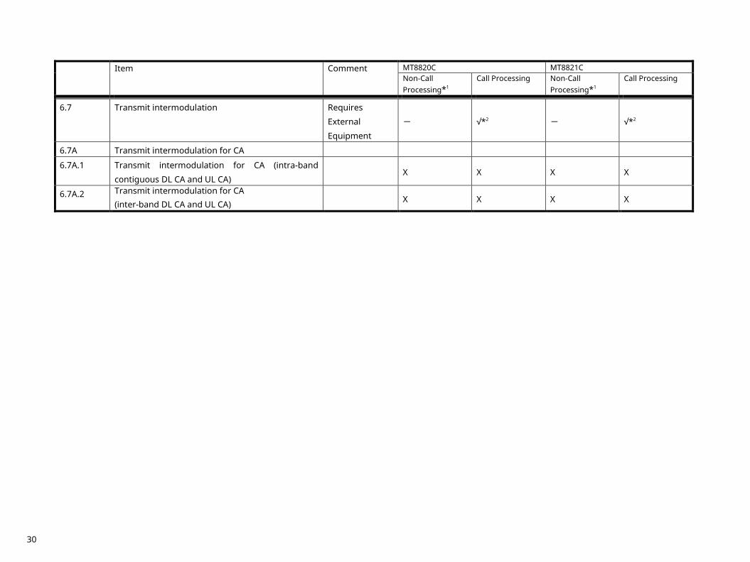
6.7 Transmit intermodulation Requires
External
Equipment
- √*2 - √*2
6.7A Transmit intermodulation for CA
6.7A.1 Transmit intermodulation for CA (intra-band
contiguous DL CA and UL CA)
X X X X
6.7A.2 Transmit intermodulation for CA (inter-band DL CA and UL CA)
X X X X
30
Item Comment MT8820C MT8821C
Non-Call Processing*1
Call Processing Non-Call Processing*1
Call Processing
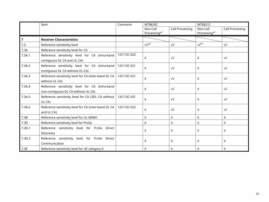
7 Receiver Characteristics
7.3 Reference sensitivity level √√*4 √√ √√*4 √√
7.3A Reference sensitivity level for CA
7.3A.1 Reference sensitivity level for CA (intra-band
contiguous DL CA and UL CA)
12C/13C-022 X √√ X √√
7.3A.2 Reference sensitivity level for CA (intra-band
contiguous DL CA without UL CA)
12C/13C-021 X √√ X √√
7.3A.3 Reference sensitivity level for CA (inter-band DL CA
without UL CA)
12C/13C-021 X √√ X √√
7.3A.4 Reference sensitivity level for CA (intra-band
non-contiguous DL CA without UL CA)
X √√ X √√
7.3A.5 Reference sensitivity level for CA (3DL CA without
UL CA)
12C/13C-031 X √√ X √√
7.3A.6 Reference sensitivity level for CA (inter-band DL CA
and UL CA)
12C/13C-022 X √√ X √√
7.3B Reference sensitivity level for UL-MIMO X X X X
7.3D Reference sensitivity level for ProSe X X X X
7.3D.1 Reference sensitivity level for ProSe Direct
Discovery
X X X X
7.3D.2 Reference sensitivity level for ProSe Direct
Communication
X X X X
7.3E Reference sensitivity level for UE category 0 X X X X
31
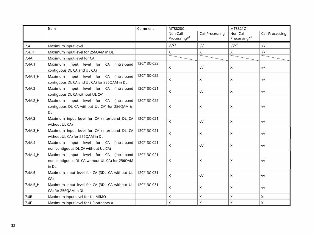
Item Comment MT8820C MT8821C
Non-Call Processing*1
Call Processing Non-Call Processing*1
Call Processing
7.4 Maximum input level √√*4 √√ √√*4 √√
7.4_H Maximum input level for 256QAM in DL X X X √√
7.4A Maximum input level for CA
7.4A.1 Maximum input level for CA (intra-band
contiguous DL CA and UL CA)
12C/13C-022 X √√ X √√
7.4A.1_H Maximum input level for CA (intra-band
contiguous DL CA and UL CA) for 256QAM in DL
12C/13C-022 X X X √√
7.4A.2 Maximum input level for CA (intra-band
contiguous DL CA without UL CA)
12C/13C-021 X √√ X √√
7.4A.2_H Maximum input level for CA (intra-band
contiguous DL CA without UL CA) for 256QAM in
DL
12C/13C-022
X X X √√
7.4A.3 Maximum input level for CA (inter-band DL CA
without UL CA)
12C/13C-021 X √√ X √√
7.4A.3_H Maximum input level for CA (inter-band DL CA
without UL CA) for 256QAM in DL
12C/13C-021 X X X √√
7.4A.4 Maximum input level for CA (intra-band
non-contiguous DL CA without UL CA)
12C/13C-021 X √√ X √√
7.4A.4_H Maximum input level for CA (intra-band
non-contiguous DL CA without UL CA) for 256QAM
in DL
12C/13C-021
X X X √√
7.4A.5 Maximum input level for CA (3DL CA without UL
CA)
12C/13C-031 X √√ X √√
7.4A.5_H Maximum input level for CA (3DL CA without UL
CA) for 256QAM in DL
12C/13C-031 X X X √√
7.4B Maximum input level for UL-MIMO X X X X
7.4E Maximum input level for UE category 0 X X X X
32
Item Comment MT8820C MT8821C
Non-Call Processing*1
Call Processing Non-Call Processing*1
Call Processing
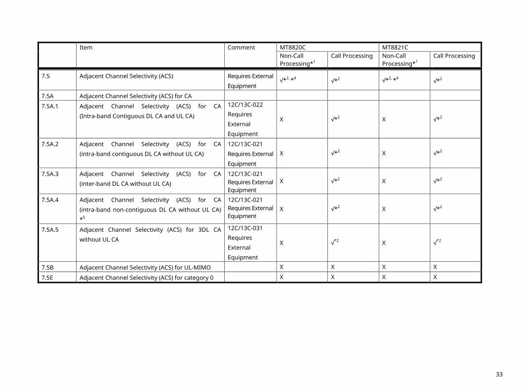
7.5 Adjacent Channel Selectivity (ACS) Requires External
Equipment √*2, *4 √*2 √*2, *4 √*2
7.5A Adjacent Channel Selectivity (ACS) for CA
7.5A.1 Adjacent Channel Selectivity (ACS) for CA
(Intra-band Contiguous DL CA and UL CA)
12C/13C-022 Requires
External
Equipment
X √*2 X √*2
7.5A.2 Adjacent Channel Selectivity (ACS) for CA
(intra-band contiguous DL CA without UL CA)
12C/13C-021
Requires External
Equipment
X √*2 X √*2
7.5A.3 Adjacent Channel Selectivity (ACS) for CA
(inter-band DL CA without UL CA)
12C/13C-021 Requires External Equipment
X √*2 X √*2
7.5A.4 Adjacent Channel Selectivity (ACS) for CA
(intra-band non-contiguous DL CA without UL CA)
*5
12C/13C-021 Requires External Equipment
X √*2 X √*2
7.5A.5 Adjacent Channel Selectivity (ACS) for 3DL CA
without UL CA
12C/13C-031 Requires
External
Equipment
X √*2 X √*2
7.5B Adjacent Channel Selectivity (ACS) for UL-MIMO X X X X
7.5E Adjacent Channel Selectivity (ACS) for category 0 X X X X
33
Item Comment MT8820C MT8821C
Non-Call Processing*1
Call Processing Non-Call Processing*1
Call Processing
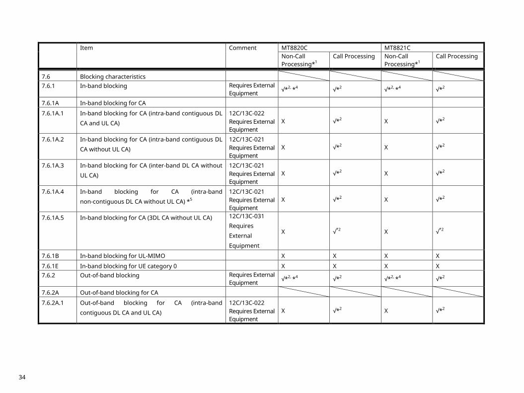
7.6 Blocking characteristics
7.6.1 In-band blocking Requires External Equipment √*2, *4 √*2 √*2, *4 √*2
7.6.1A In-band blocking for CA
7.6.1A.1 In-band blocking for CA (intra-band contiguous DL
CA and UL CA)
12C/13C-022 Requires External Equipment
X √*2 X √*2
7.6.1A.2 In-band blocking for CA (intra-band contiguous DL
CA without UL CA)
12C/13C-021 Requires External Equipment
X √*2 X √*2
7.6.1A.3 In-band blocking for CA (inter-band DL CA without
UL CA)
12C/13C-021 Requires External Equipment
X √*2 X √*2
7.6.1A.4 In-band blocking for CA (intra-band
non-contiguous DL CA without UL CA) *5
12C/13C-021 Requires External Equipment
X √*2 X √*2
7.6.1A.5 In-band blocking for CA (3DL CA without UL CA) 12C/13C-031 Requires
External
Equipment
X √*2 X √*2
7.6.1B In-band blocking for UL-MIMO X X X X
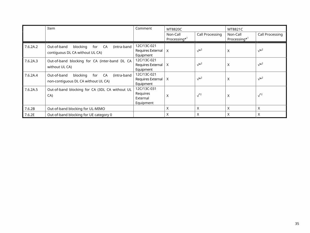
7.6.1E In-band blocking for UE category 0 X X X X 7.6.2 Out-of-band blocking Requires External
Equipment √*2, *4 √*2 √*2, *4 √*2
7.6.2A Out-of-band blocking for CA
7.6.2A.1 Out-of-band blocking for CA (intra-band
contiguous DL CA and UL CA)
12C/13C-022 Requires External Equipment
X √*2 X √*2
34
Item Comment MT8820C MT8821C
Non-Call Processing*1
Call Processing Non-Call Processing*1
Call Processing
7.6.2A.2 Out-of-band blocking for CA (intra-band
contiguous DL CA without UL CA)
12C/13C-021 Requires External Equipment
X √*2 X √*2
7.6.2A.3 Out-of-band blocking for CA (inter-band DL CA
without UL CA)
12C/13C-021 Requires External Equipment
X √*2 X √*2
7.6.2A.4 Out-of-band blocking for CA (intra-band
non-contiguous DL CA without UL CA)
12C/13C-021 Requires External Equipment
X √*2 X √*2
7.6.2A.5 Out-of-band blocking for CA (3DL CA without UL
CA)
12C/13C-031 Requires External Equipment
X √*2 X √*2
7.6.2B Out-of-band blocking for UL-MIMO X X X X
7.6.2E Out-of-band blocking for UE category 0 X X X X
35
Item Comment MT8820C MT8821C
Non-Call Processing*1
Call Processing Non-Call Processing*1
Call Processing
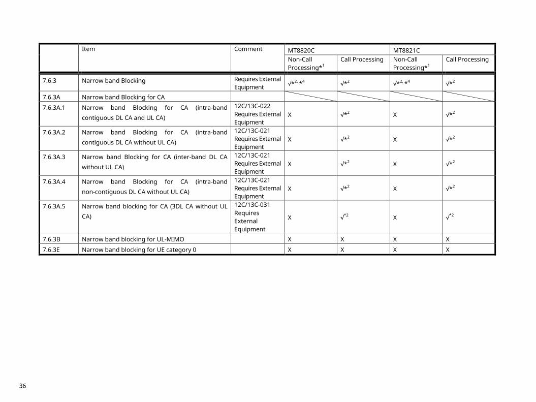
7.6.3 Narrow band Blocking Requires External Equipment √*2, *4 √*2 √*2, *4 √*2
7.6.3A Narrow band Blocking for CA
7.6.3A.1 Narrow band Blocking for CA (intra-band
contiguous DL CA and UL CA)
12C/13C-022 Requires External Equipment
X √*2 X √*2
7.6.3A.2 Narrow band Blocking for CA (intra-band
contiguous DL CA without UL CA)
12C/13C-021 Requires External Equipment
X √*2 X √*2
7.6.3A.3 Narrow band Blocking for CA (inter-band DL CA
without UL CA)
12C/13C-021 Requires External Equipment
X √*2 X √*2
7.6.3A.4 Narrow band Blocking for CA (intra-band
non-contiguous DL CA without UL CA)
12C/13C-021 Requires External Equipment
X √*2 X √*2
7.6.3A.5 Narrow band blocking for CA (3DL CA without UL
CA)
12C/13C-031 Requires External Equipment
X √*2 X √*2
7.6.3B Narrow band blocking for UL-MIMO X X X X
7.6.3E Narrow band blocking for UE category 0 X X X X
36
Item Comment MT8820C MT8821C
Non-Call Processing*1
Call Processing Non-Call Processing*1
Call Processing
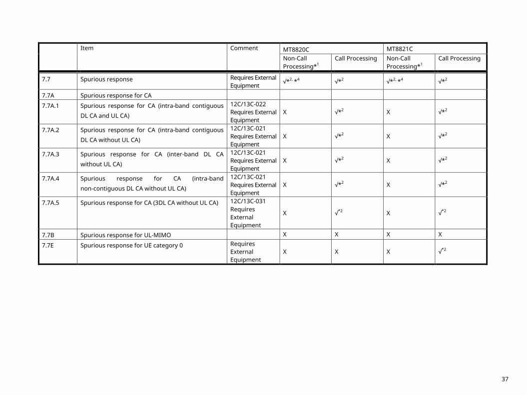
7.7 Spurious response Requires External Equipment
√*2, *4 √*2 √*2, *4 √*2
7.7A Spurious response for CA
7.7A.1 Spurious response for CA (intra-band contiguous
DL CA and UL CA)
12C/13C-022 Requires External Equipment
X √*2 X √*2
7.7A.2 Spurious response for CA (intra-band contiguous
DL CA without UL CA)
12C/13C-021 Requires External Equipment
X √*2 X √*2
7.7A.3 Spurious response for CA (inter-band DL CA
without UL CA)
12C/13C-021 Requires External Equipment
X √*2 X √*2
7.7A.4 Spurious response for CA (intra-band
non-contiguous DL CA without UL CA)
12C/13C-021 Requires External Equipment
X √*2 X √*2
7.7A.5 Spurious response for CA (3DL CA without UL CA) 12C/13C-031 Requires External Equipment
X √*2 X √*2
7.7B Spurious response for UL-MIMO X X X X
7.7E Spurious response for UE category 0 Requires External Equipment
X X X √*2
37
Item Comment MT8820C MT8821C Non-Call Processing*1
Call Processing Non-Call Processing*1
Call Processing
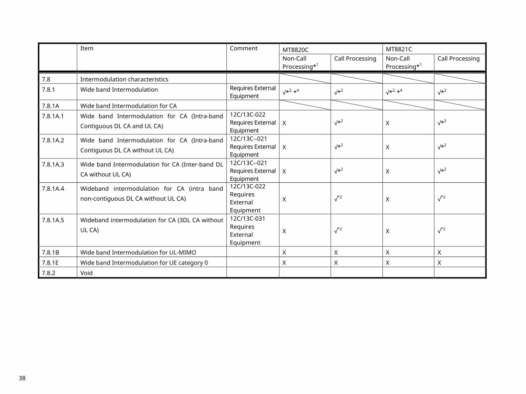
7.8 Intermodulation characteristics
7.8.1 Wide band Intermodulation Requires External Equipment √*2, *4 √*2 √*2, *4 √*2
7.8.1A Wide band Intermodulation for CA
7.8.1A.1 Wide band Intermodulation for CA (Intra-band
Contiguous DL CA and UL CA)
12C/13C-022 Requires External Equipment
X √*2 X √*2
7.8.1A.2 Wide band Intermodulation for CA (Intra-band
Contiguous DL CA without UL CA)
12C/13C--021 Requires External Equipment
X √*2 X √*2
7.8.1A.3 Wide band Intermodulation for CA (Inter-band DL
CA without UL CA)
12C/13C--021 Requires External Equipment
X √*2 X √*2
7.8.1A.4 Wideband intermodulation for CA (intra band
non-contiguous DL CA without UL CA)
12C/13C-022 Requires External Equipment
X √*2 X √*2
7.8.1A.5 Wideband intermodulation for CA (3DL CA without
UL CA)
12C/13C-031 Requires External Equipment
X √*2 X √*2
7.8.1B Wide band Intermodulation for UL-MIMO X X X X
7.8.1E Wide band Intermodulation for UE category 0 X X X X
7.8.2 Void
38
Item Comment MT8820C MT8821C
Non-Call Processing*1
Call Processing Non-Call Processing*1
Call Processing
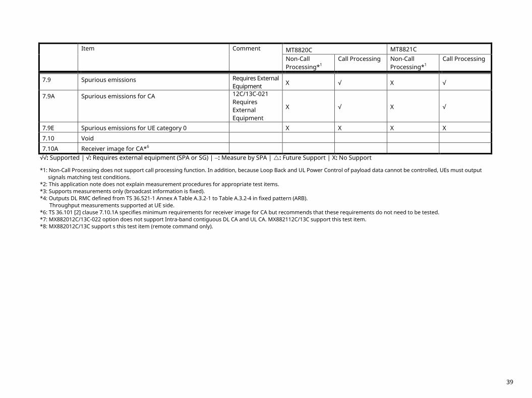
7.9 Spurious emissions Requires External Equipment X √ X √
7.9A Spurious emissions for CA 12C/13C-021 Requires External Equipment
X √ X √
7.9E Spurious emissions for UE category 0 X X X X
7.10 Void
7.10A Receiver image for CA*6 √√: Supported | √: Requires external equipment (SPA or SG) | −: Measure by SPA | : Future Support | X: No Support *1: Non-Call Processing does not support call processing function. In addition, because Loop Back and UL Power Control of payload data cannot be controlled, UEs must output
signals matching test conditions. *2: This application note does not explain measurement procedures for appropriate test items. *3: Supports measurements only (broadcast information is fixed). *4: Outputs DL RMC defined from TS 36.521-1 Annex A Table A.3.2-1 to Table A.3.2-4 in fixed pattern (ARB).
Throughput measurements supported at UE side. *6: TS 36.101 [2] clause 7.10.1A specifies minimum requirements for receiver image for CA but recommends that these requirements do not need to be tested. *7: MX882012C/13C-022 option does not support Intra-band contiguous DL CA and UL CA. MX882112C/13C support this test item. *8: MX882012C/13C support s this test item (remote command only).
39
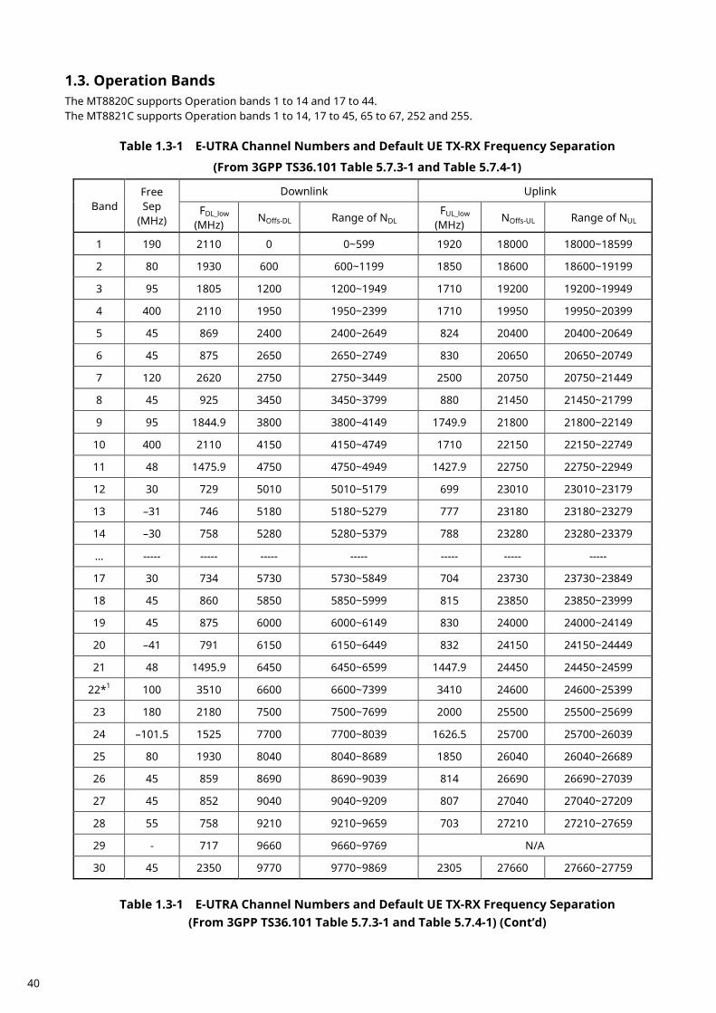
Operation Bands 1.3.The MT8820C supports Operation bands 1 to 14 and 17 to 44. The MT8821C supports Operation bands 1 to 14, 17 to 45, 65 to 67, 252 and 255.
Table 1.3-1 E-UTRA Channel Numbers and Default UE TX-RX Frequency Separation
(From 3GPP TS36.101 Table 5.7.3-1 and Table 5.7.4-1)
Band Free Sep
(MHz)
Downlink Uplink
FDL_low (MHz)
NOffs-DL Range of NDL FUL_low
(MHz) NOffs-UL Range of NUL
1 190 2110 0 0~599 1920 18000 18000~18599
2 80 1930 600 600~1199 1850 18600 18600~19199
3 95 1805 1200 1200~1949 1710 19200 19200~19949
4 400 2110 1950 1950~2399 1710 19950 19950~20399
5 45 869 2400 2400~2649 824 20400 20400~20649
6 45 875 2650 2650~2749 830 20650 20650~20749
7 120 2620 2750 2750~3449 2500 20750 20750~21449
8 45 925 3450 3450~3799 880 21450 21450~21799
9 95 1844.9 3800 3800~4149 1749.9 21800 21800~22149
10 400 2110 4150 4150~4749 1710 22150 22150~22749
11 48 1475.9 4750 4750~4949 1427.9 22750 22750~22949
12 30 729 5010 5010~5179 699 23010 23010~23179
13 –31 746 5180 5180~5279 777 23180 23180~23279
14 –30 758 5280 5280~5379 788 23280 23280~23379
… ----- ----- ----- ----- ----- ----- -----
17 30 734 5730 5730~5849 704 23730 23730~23849
18 45 860 5850 5850~5999 815 23850 23850~23999
19 45 875 6000 6000~6149 830 24000 24000~24149
20 –41 791 6150 6150~6449 832 24150 24150~24449
21 48 1495.9 6450 6450~6599 1447.9 24450 24450~24599
22*1 100 3510 6600 6600~7399 3410 24600 24600~25399
23 180 2180 7500 7500~7699 2000 25500 25500~25699
24 –101.5 1525 7700 7700~8039 1626.5 25700 25700~26039
25 80 1930 8040 8040~8689 1850 26040 26040~26689
26 45 859 8690 8690~9039 814 26690 26690~27039
27 45 852 9040 9040~9209 807 27040 27040~27209
28 55 758 9210 9210~9659 703 27210 27210~27659
29 - 717 9660 9660~9769 N/A
30 45 2350 9770 9770~9869 2305 27660 27660~27759
Table 1.3-1 E-UTRA Channel Numbers and Default UE TX-RX Frequency Separation
(From 3GPP TS36.101 Table 5.7.3-1 and Table 5.7.4-1) (Cont’d)
40
Band Freq Sep
(MHz)
Downlink Uplink
FDL_low (MHz)
NOffs-DL Range of NDL FUL_low (MHz)
NOffs-UL Range of NUL
31 10 462.5 9870 9870~9919 452.5 27760 27760~27809
32 - 1452 9920 9920~10359 N/A
33 0 1900 36000 36000~36199 1900 36000 36000~36199
34 0 2010 36200 36200~36349 2010 36200 36200~36349
35 0 1850 36350 36350~36949 1850 36350 36350~36949
36 0 1930 36950 36950~37549 1930 36950 36950~37549
37 0 1910 37550 37550~37749 1910 37550 37550~37749
38 0 2570 37750 37750~38249 2570 37750 37750~38249
39 0 1880 38250 38250~38649 1880 38250 38250~38649
40 0 2300 38650 38650~39649 2300 38650 38650~39649
41 0 2496 39650 39650~41589 2496 39650 39650~41589
42*1 0 3400 41590 41590~43589 3400 41590 41590~43589
43*1 0 3600 43590 43590~45589 3600 43590 43590~45589
44 0 703 45590 45590~46589 703 45590 45590~46589
45 0 1447 46590 46590~46789 1447 46590 46590~46789
46*2 0 5150 46790 46790~54539 5150 46790 46790~54539
--- --- --- --- --- --- --- ---
48 0 3550 55240 55240~56739 3550 55240 55240~56739 --- --- --- --- --- --- --- ---
65 190 2110 65536 65536~66435 1920 131072 131072~131971
66 400 2110 66436 66436~67335 1710 131972 131972~132671
67 - 738 67336 67336~67535 N/A
68 55 753 67536 67536~67835 698 132672 132672~132971 69 --- 2570 67836 67836~68335 N/A 70 300 1995 68336 68336~68585 1695 132972 132972~133121
70*3 295 1995 68336 68336~68585 1700 133022 133022~133121
--- --- --- --- --- --- --- ---
250*1 0 3550 253644 253644~255143 3550 253644 253644~255143
--- --- --- --- --- --- --- ---
252*2 - 5150 255144 255144~256143 N/A
--- --- --- --- --- ---
255*2 - 5725 260894 260894~262143 N/A
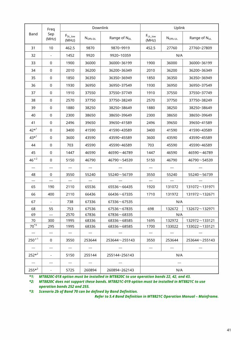
*1: MT8820C-018 option must be installed in MT8820C to use operation bands 22, 42, and 43. *2: MT8820C does not support these bands. MT8821C-019 option must be installed in MT8821C to use
operation bands 252 and 255. *3: Scenario 2b of Band 70 can be defined by Band Definition.
Refer to 5.4 Band Definition in MT8821C Operation Manual – Mainframe.
41
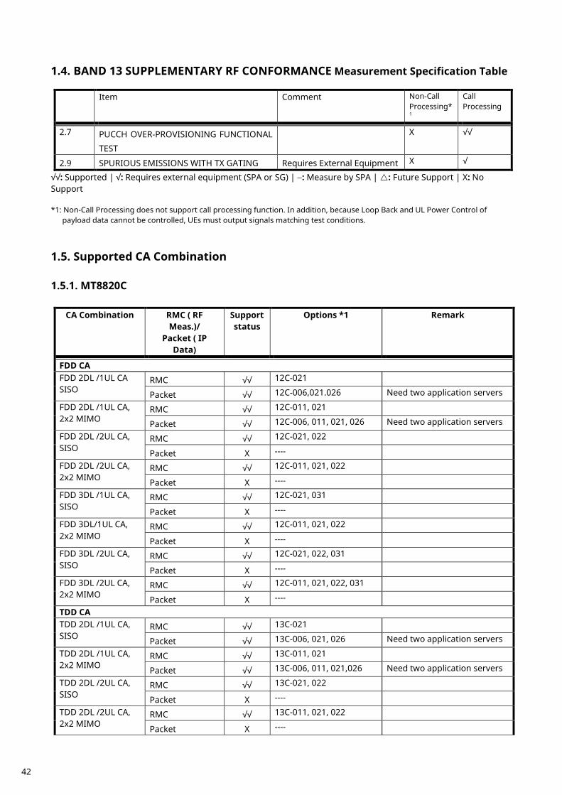
BAND 13 SUPPLEMENTARY RF CONFORMANCE Measurement Specification Table 1.4.
Item Comment Non-Call Processing*1
Call Processing
2.7 PUCCH OVER-PROVISIONING FUNCTIONAL
TEST
X √√
2.9 SPURIOUS EMISSIONS WITH TX GATING Requires External Equipment X √
√√: Supported | √: Requires external equipment (SPA or SG) | −: Measure by SPA | : Future Support | X: No Support *1: Non-Call Processing does not support call processing function. In addition, because Loop Back and UL Power Control of
payload data cannot be controlled, UEs must output signals matching test conditions.
Supported CA Combination 1.5.
MT8820C 1.5.1.
CA Combination RMC ( RF Meas.)/
Packet ( IP Data)
Support status
Options *1 Remark
FDD CA FDD 2DL /1UL CA SISO
RMC √√ 12C-021
Packet √√ 12C-006,021.026 Need two application servers
FDD 2DL /1UL CA, 2x2 MIMO
RMC √√ 12C-011, 021
Packet √√ 12C-006, 011, 021, 026 Need two application servers
FDD 2DL /2UL CA, SISO
RMC √√ 12C-021, 022
Packet X ----
FDD 2DL /2UL CA, 2x2 MIMO
RMC √√ 12C-011, 021, 022
Packet X ----
FDD 3DL /1UL CA, SISO
RMC √√ 12C-021, 031
Packet X ----
FDD 3DL/1UL CA, 2x2 MIMO
RMC √√ 12C-011, 021, 022
Packet X ----
FDD 3DL /2UL CA, SISO
RMC √√ 12C-021, 022, 031
Packet X ----
FDD 3DL /2UL CA, 2x2 MIMO
RMC √√ 12C-011, 021, 022, 031
Packet X ----
TDD CA TDD 2DL /1UL CA, SISO
RMC √√ 13C-021
Packet √√ 13C-006, 021, 026 Need two application servers
TDD 2DL /1UL CA, 2x2 MIMO
RMC √√ 13C-011, 021
Packet √√ 13C-006, 011, 021,026 Need two application servers
TDD 2DL /2UL CA, SISO
RMC √√ 13C-021, 022
Packet X ----
TDD 2DL /2UL CA, 2x2 MIMO
RMC √√ 13C-011, 021, 022
Packet X ----
42
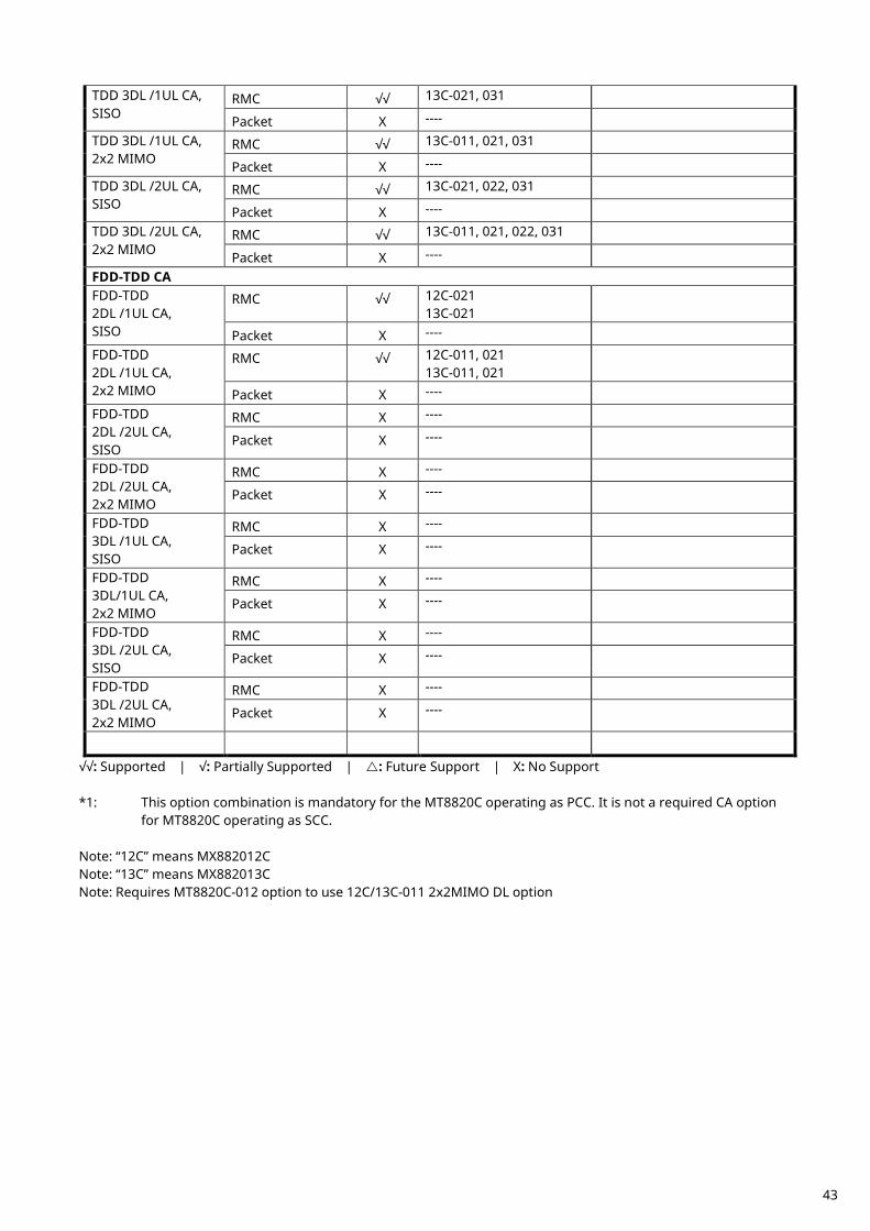
TDD 3DL /1UL CA, SISO
RMC √√ 13C-021, 031
Packet X ----
TDD 3DL /1UL CA, 2x2 MIMO
RMC √√ 13C-011, 021, 031
Packet X ----
TDD 3DL /2UL CA, SISO
RMC √√ 13C-021, 022, 031
Packet X ----
TDD 3DL /2UL CA, 2x2 MIMO
RMC √√ 13C-011, 021, 022, 031
Packet X ----
FDD-TDD CA FDD-TDD 2DL /1UL CA, SISO
RMC √√ 12C-021 13C-021
Packet X ----
FDD-TDD 2DL /1UL CA, 2x2 MIMO
RMC √√ 12C-011, 021 13C-011, 021
Packet X ----
FDD-TDD 2DL /2UL CA, SISO
RMC X ----
Packet X ----
FDD-TDD 2DL /2UL CA, 2x2 MIMO
RMC X ----
Packet X ----
FDD-TDD 3DL /1UL CA, SISO
RMC X ----
Packet X ----
FDD-TDD 3DL/1UL CA, 2x2 MIMO
RMC X ----
Packet X ----
FDD-TDD 3DL /2UL CA, SISO
RMC X ----
Packet X ----
FDD-TDD 3DL /2UL CA, 2x2 MIMO
RMC X ----
Packet X ----
√√: Supported | √: Partially Supported | : Future Support | X: No Support *1: This option combination is mandatory for the MT8820C operating as PCC. It is not a required CA option
for MT8820C operating as SCC. Note: “12C” means MX882012C Note: “13C” means MX882013C Note: Requires MT8820C-012 option to use 12C/13C-011 2x2MIMO DL option
43
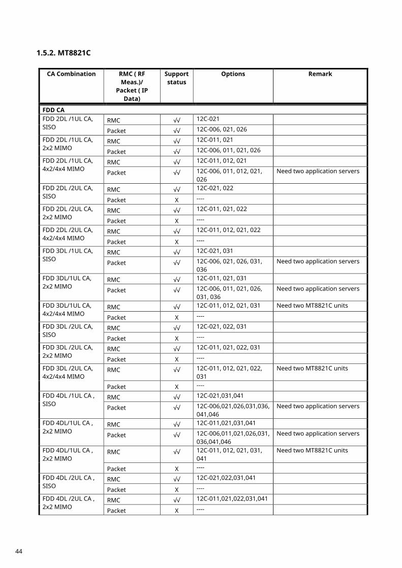
MT8821C 1.5.2.
CA Combination RMC ( RF
Meas.)/ Packet ( IP
Data)
Support status
Options Remark
FDD CA FDD 2DL /1UL CA, SISO
RMC √√ 12C-021
Packet √√ 12C-006, 021, 026
FDD 2DL /1UL CA, 2x2 MIMO
RMC √√ 12C-011, 021
Packet √√ 12C-006, 011, 021, 026
FDD 2DL /1UL CA, 4x2/4x4 MIMO
RMC √√ 12C-011, 012, 021
Packet √√ 12C-006, 011, 012, 021, 026
Need two application servers
FDD 2DL /2UL CA, SISO
RMC √√ 12C-021, 022
Packet X ----
FDD 2DL /2UL CA, 2x2 MIMO
RMC √√ 12C-011, 021, 022
Packet X ----
FDD 2DL /2UL CA, 4x2/4x4 MIMO
RMC √√ 12C-011, 012, 021, 022
Packet X ----
FDD 3DL /1UL CA, SISO
RMC √√ 12C-021, 031
Packet √√ 12C-006, 021, 026, 031, 036
Need two application servers
FDD 3DL/1UL CA, 2x2 MIMO
RMC √√ 12C-011, 021, 031
Packet √√ 12C-006, 011, 021, 026, 031, 036
Need two application servers
FDD 3DL/1UL CA, 4x2/4x4 MIMO
RMC √√ 12C-011, 012, 021, 031 Need two MT8821C units
Packet X ----
FDD 3DL /2UL CA, SISO
RMC √√ 12C-021, 022, 031
Packet X ----
FDD 3DL /2UL CA, 2x2 MIMO
RMC √√ 12C-011, 021, 022, 031
Packet X ----
FDD 3DL /2UL CA, 4x2/4x4 MIMO
RMC √√ 12C-011, 012, 021, 022, 031
Need two MT8821C units
Packet X ----
FDD 4DL /1UL CA , SISO
RMC √√ 12C-021,031,041
Packet √√ 12C-006,021,026,031,036,041,046
Need two application servers
FDD 4DL/1UL CA , 2x2 MIMO
RMC √√ 12C-011,021,031,041
Packet √√ 12C-006,011,021,026,031,036,041,046
Need two application servers
FDD 4DL/1UL CA , 2x2 MIMO
RMC √√ 12C-011, 012, 021, 031, 041
Need two MT8821C units
Packet X ----
FDD 4DL /2UL CA , SISO
RMC √√ 12C-021,022,031,041
Packet X ----
FDD 4DL /2UL CA , 2x2 MIMO
RMC √√ 12C-011,021,022,031,041
Packet X ----
44
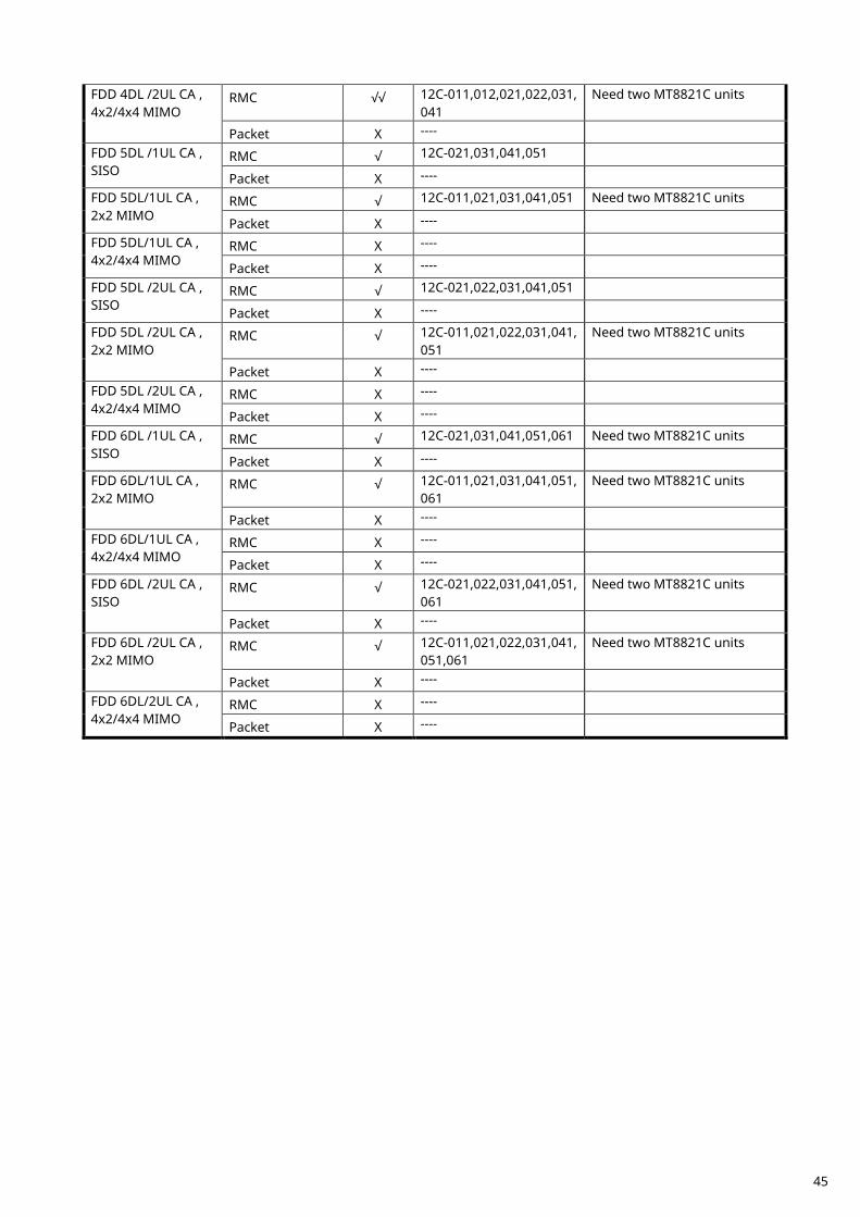
FDD 4DL /2UL CA , 4x2/4x4 MIMO
RMC √√ 12C-011,012,021,022,031,041
Need two MT8821C units
Packet X ----
FDD 5DL /1UL CA , SISO
RMC √ 12C-021,031,041,051
Packet X ----
FDD 5DL/1UL CA , 2x2 MIMO
RMC √ 12C-011,021,031,041,051 Need two MT8821C units
Packet X ----
FDD 5DL/1UL CA , 4x2/4x4 MIMO
RMC X ----
Packet X ----
FDD 5DL /2UL CA , SISO
RMC √ 12C-021,022,031,041,051
Packet X ----
FDD 5DL /2UL CA , 2x2 MIMO
RMC √ 12C-011,021,022,031,041,051
Need two MT8821C units
Packet X ----
FDD 5DL /2UL CA , 4x2/4x4 MIMO
RMC X ----
Packet X ----
FDD 6DL /1UL CA , SISO
RMC √ 12C-021,031,041,051,061 Need two MT8821C units
Packet X ----
FDD 6DL/1UL CA , 2x2 MIMO
RMC √ 12C-011,021,031,041,051,061
Need two MT8821C units
Packet X ----
FDD 6DL/1UL CA , 4x2/4x4 MIMO
RMC X ----
Packet X ----
FDD 6DL /2UL CA , SISO
RMC √ 12C-021,022,031,041,051,061
Need two MT8821C units
Packet X ----
FDD 6DL /2UL CA , 2x2 MIMO
RMC √ 12C-011,021,022,031,041,051,061
Need two MT8821C units
Packet X ----
FDD 6DL/2UL CA , 4x2/4x4 MIMO
RMC X ----
Packet X ----
45
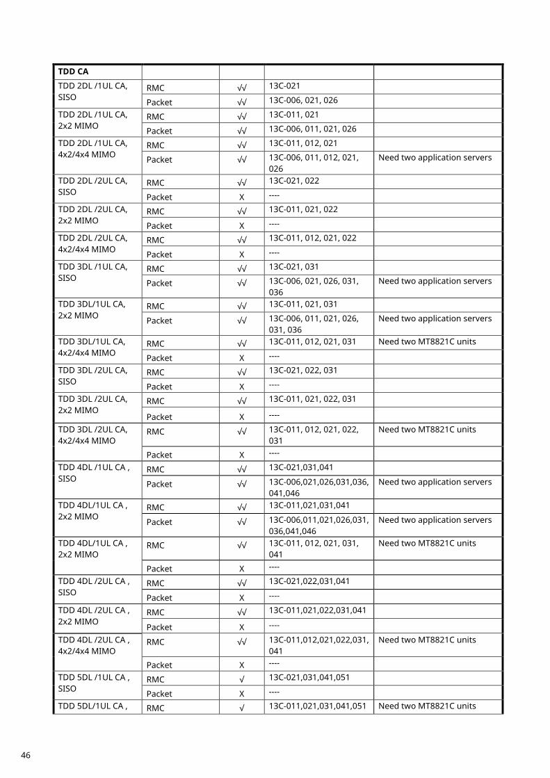
TDD CA
TDD 2DL /1UL CA, SISO
RMC √√ 13C-021
Packet √√ 13C-006, 021, 026
TDD 2DL /1UL CA, 2x2 MIMO
RMC √√ 13C-011, 021
Packet √√ 13C-006, 011, 021, 026
TDD 2DL /1UL CA, 4x2/4x4 MIMO
RMC √√ 13C-011, 012, 021
Packet √√ 13C-006, 011, 012, 021, 026
Need two application servers
TDD 2DL /2UL CA, SISO
RMC √√ 13C-021, 022
Packet X ----
TDD 2DL /2UL CA, 2x2 MIMO
RMC √√ 13C-011, 021, 022
Packet X ----
TDD 2DL /2UL CA, 4x2/4x4 MIMO
RMC √√ 13C-011, 012, 021, 022
Packet X ----
TDD 3DL /1UL CA, SISO
RMC √√ 13C-021, 031
Packet √√ 13C-006, 021, 026, 031, 036
Need two application servers
TDD 3DL/1UL CA, 2x2 MIMO
RMC √√ 13C-011, 021, 031
Packet √√ 13C-006, 011, 021, 026, 031, 036
Need two application servers
TDD 3DL/1UL CA, 4x2/4x4 MIMO
RMC √√ 13C-011, 012, 021, 031 Need two MT8821C units
Packet X ----
TDD 3DL /2UL CA, SISO
RMC √√ 13C-021, 022, 031
Packet X ----
TDD 3DL /2UL CA, 2x2 MIMO
RMC √√ 13C-011, 021, 022, 031
Packet X ----
TDD 3DL /2UL CA, 4x2/4x4 MIMO
RMC √√ 13C-011, 012, 021, 022, 031
Need two MT8821C units
Packet X ----
TDD 4DL /1UL CA , SISO
RMC √√ 13C-021,031,041
Packet √√ 13C-006,021,026,031,036,041,046
Need two application servers
TDD 4DL/1UL CA , 2x2 MIMO
RMC √√ 13C-011,021,031,041
Packet √√ 13C-006,011,021,026,031,036,041,046
Need two application servers
TDD 4DL/1UL CA , 2x2 MIMO
RMC √√ 13C-011, 012, 021, 031, 041
Need two MT8821C units
Packet X ----
TDD 4DL /2UL CA , SISO
RMC √√ 13C-021,022,031,041
Packet X ----
TDD 4DL /2UL CA , 2x2 MIMO
RMC √√ 13C-011,021,022,031,041
Packet X ----
TDD 4DL /2UL CA , 4x2/4x4 MIMO
RMC √√ 13C-011,012,021,022,031,041
Need two MT8821C units
Packet X ----
TDD 5DL /1UL CA , SISO
RMC √ 13C-021,031,041,051
Packet X ----
TDD 5DL/1UL CA , RMC √ 13C-011,021,031,041,051 Need two MT8821C units
46
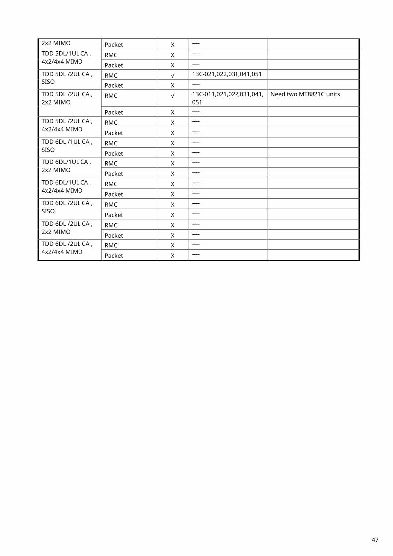
2x2 MIMO Packet X ----
TDD 5DL/1UL CA , 4x2/4x4 MIMO
RMC X ----
Packet X ----
TDD 5DL /2UL CA , SISO
RMC √ 13C-021,022,031,041,051
Packet X ----
TDD 5DL /2UL CA , 2x2 MIMO
RMC √ 13C-011,021,022,031,041,051
Need two MT8821C units
Packet X ----
TDD 5DL /2UL CA , 4x2/4x4 MIMO
RMC X ----
Packet X ----
TDD 6DL /1UL CA , SISO
RMC X ----
Packet X ----
TDD 6DL/1UL CA , 2x2 MIMO
RMC X ----
Packet X ----
TDD 6DL/1UL CA , 4x2/4x4 MIMO
RMC X ----
Packet X ----
TDD 6DL /2UL CA , SISO
RMC X ----
Packet X ----
TDD 6DL /2UL CA , 2x2 MIMO
RMC X ----
Packet X ----
TDD 6DL /2UL CA , 4x2/4x4 MIMO
RMC X ----
Packet X ----
47
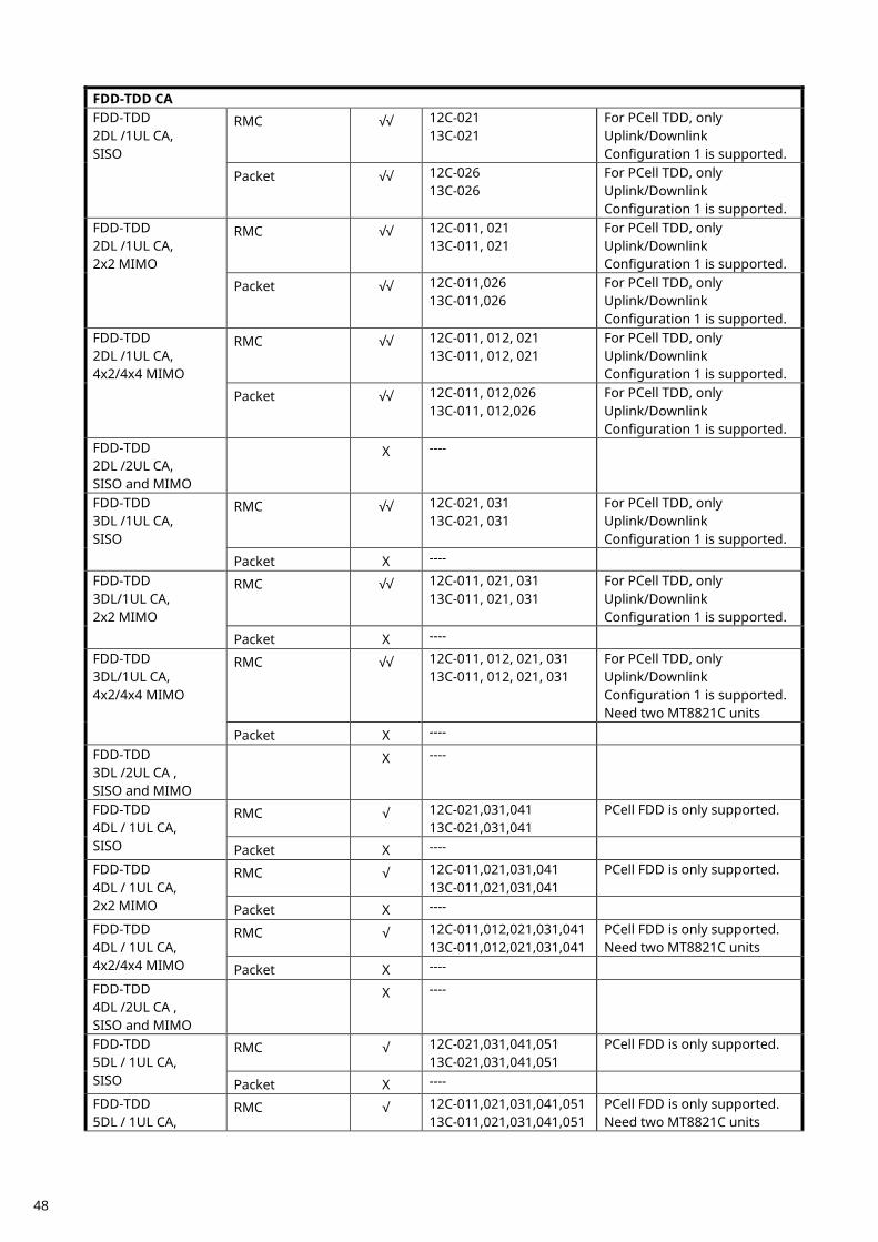
FDD-TDD CA FDD-TDD 2DL /1UL CA, SISO
RMC √√ 12C-021 13C-021
For PCell TDD, only Uplink/Downlink Configuration 1 is supported.
Packet √√ 12C-026 13C-026
For PCell TDD, only Uplink/Downlink Configuration 1 is supported.
FDD-TDD 2DL /1UL CA, 2x2 MIMO
RMC √√ 12C-011, 021 13C-011, 021
For PCell TDD, only Uplink/Downlink Configuration 1 is supported.
Packet √√ 12C-011,026 13C-011,026
For PCell TDD, only Uplink/Downlink Configuration 1 is supported.
FDD-TDD 2DL /1UL CA, 4x2/4x4 MIMO
RMC √√ 12C-011, 012, 021 13C-011, 012, 021
For PCell TDD, only Uplink/Downlink Configuration 1 is supported.
Packet √√ 12C-011, 012,026 13C-011, 012,026
For PCell TDD, only Uplink/Downlink Configuration 1 is supported.
FDD-TDD 2DL /2UL CA, SISO and MIMO
X ----
FDD-TDD 3DL /1UL CA, SISO
RMC √√ 12C-021, 031 13C-021, 031
For PCell TDD, only Uplink/Downlink Configuration 1 is supported.
Packet X ----
FDD-TDD 3DL/1UL CA, 2x2 MIMO
RMC √√ 12C-011, 021, 031 13C-011, 021, 031
For PCell TDD, only Uplink/Downlink Configuration 1 is supported.
Packet X ----
FDD-TDD 3DL/1UL CA, 4x2/4x4 MIMO
RMC √√ 12C-011, 012, 021, 031 13C-011, 012, 021, 031
For PCell TDD, only Uplink/Downlink Configuration 1 is supported. Need two MT8821C units
Packet X ----
FDD-TDD 3DL /2UL CA , SISO and MIMO
X ----
FDD-TDD 4DL / 1UL CA, SISO
RMC √ 12C-021,031,041 13C-021,031,041
PCell FDD is only supported.
Packet X ----
FDD-TDD 4DL / 1UL CA, 2x2 MIMO
RMC √ 12C-011,021,031,041 13C-011,021,031,041
PCell FDD is only supported.
Packet X ----
FDD-TDD 4DL / 1UL CA, 4x2/4x4 MIMO
RMC √ 12C-011,012,021,031,041 13C-011,012,021,031,041
PCell FDD is only supported. Need two MT8821C units
Packet X ----
FDD-TDD 4DL /2UL CA , SISO and MIMO
X ----
FDD-TDD 5DL / 1UL CA, SISO
RMC √ 12C-021,031,041,051 13C-021,031,041,051
PCell FDD is only supported.
Packet X ----
FDD-TDD 5DL / 1UL CA,
RMC √ 12C-011,021,031,041,051 13C-011,021,031,041,051
PCell FDD is only supported. Need two MT8821C units
48
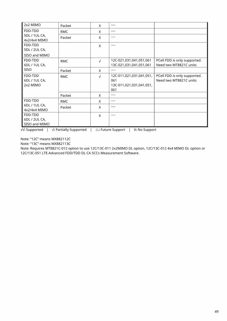
2x2 MIMO Packet X ----
FDD-TDD 5DL / 1UL CA, 4x2/4x4 MIMO
RMC X ----
Packet X ----
FDD-TDD 5DL / 2UL CA, SISO and MIMO
X ----
FDD-TDD 6DL / 1UL CA, SISO
RMC √ 12C-021,031,041,051,061 13C-021,031,041,051,061
PCell FDD is only supported. Need two MT8821C units
Packet X ----
FDD-TDD 6DL / 1UL CA, 2x2 MIMO
RMC √ 12C-011,021,031,041,051,061 13C-011,021,031,041,051,061
PCell FDD is only supported. Need two MT8821C units
Packet X ----
FDD-TDD 6DL / 1UL CA, 4x2/4x4 MIMO
RMC X ----
Packet X ----
FDD-TDD 6DL / 2UL CA, SISO and MIMO
X ----
√√: Supported | √: Partially Supported | : Future Support | X: No Support Note: “12C” means MX882112C Note: “13C” means MX882113C Note: Requires MT8821C-012 option to use 12C/13C-011 2x2MIMO DL option, 12C/13C-012 4x4 MIMO DL option or 12C/13C-051 LTE-Advanced FDD/TDD DL CA 5CCs Measurement Software.
49
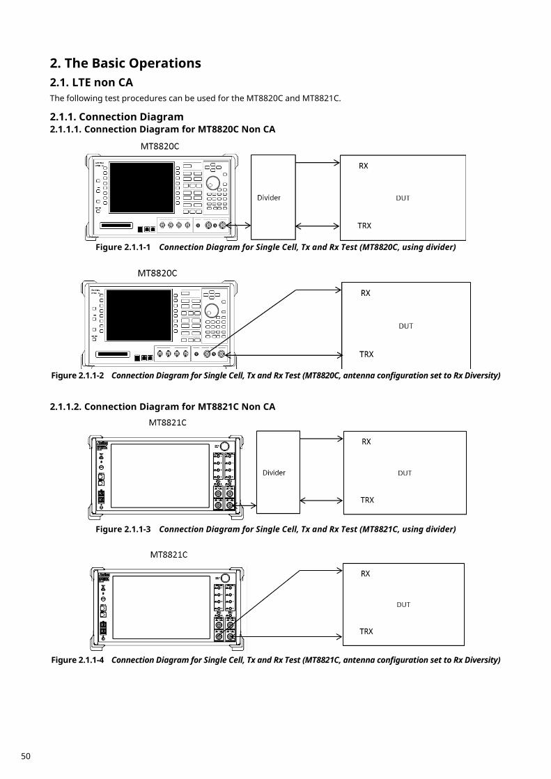
The Basic Operations 2. LTE non CA 2.1.
The following test procedures can be used for the MT8820C and MT8821C.
Connection Diagram 2.1.1.2.1.1.1. Connection Diagram for MT8820C Non CA
Figure 2.1.1-1 Connection Diagram for Single Cell, Tx and Rx Test (MT8820C, using divider)
Figure 2.1.1-2 Connection Diagram for Single Cell, Tx and Rx Test (MT8820C, antenna configuration set to Rx Diversity) 2.1.1.2. Connection Diagram for MT8821C Non CA
Figure 2.1.1-3 Connection Diagram for Single Cell, Tx and Rx Test (MT8821C, using divider)
Figure 2.1.1-4 Connection Diagram for Single Cell, Tx and Rx Test (MT8821C, antenna configuration set to Rx Diversity)
50
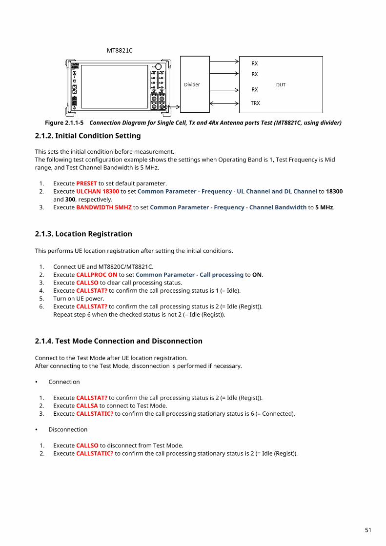
Figure 2.1.1-5 Connection Diagram for Single Cell, Tx and 4Rx Antenna ports Test (MT8821C, using divider)
Initial Condition Setting 2.1.2.
This sets the initial condition before measurement. The following test configuration example shows the settings when Operating Band is 1, Test Frequency is Mid range, and Test Channel Bandwidth is 5 MHz.
1. Execute PRESET to set default parameter. 2. Execute ULCHAN 18300 to set Common Parameter - Frequency - UL Channel and DL Channel to 18300
and 300, respectively. 3. Execute BANDWIDTH 5MHZ to set Common Parameter - Frequency - Channel Bandwidth to 5 MHz.
Location Registration 2.1.3. This performs UE location registration after setting the initial conditions.
1. Connect UE and MT8820C/MT8821C. 2. Execute CALLPROC ON to set Common Parameter - Call processing to ON. 3. Execute CALLSO to clear call processing status. 4. Execute CALLSTAT? to confirm the call processing status is 1 (= Idle). 5. Turn on UE power. 6. Execute CALLSTAT? to confirm the call processing status is 2 (= Idle (Regist)).
Repeat step 6 when the checked status is not 2 (= Idle (Regist)).
Test Mode Connection and Disconnection 2.1.4. Connect to the Test Mode after UE location registration. After connecting to the Test Mode, disconnection is performed if necessary. Connection
1. Execute CALLSTAT? to confirm the call processing status is 2 (= Idle (Regist)). 2. Execute CALLSA to connect to Test Mode. 3. Execute CALLSTATIC? to confirm the call processing stationary status is 6 (= Connected).
Disconnection
1. Execute CALLSO to disconnect from Test Mode. 2. Execute CALLSTATIC? to confirm the call processing stationary status is 2 (= Idle (Regist)).
51
Broadcast Information Update 2.1.5. When changing broadcast information, the UE must be notified of the change using one of the following methods. The method differs according to the UE in use.
A) Execute RRC Connection Reconfiguration Notify the broadcast information update using the RRC Connection Reconfiguration message. It updates information without ending a call. Use this procedure.
1. Execute RRCUPDATE RRCMSG to set Call Processing Parameter - radioResourceConfigCommon Update to RRC Message.
NOTE 1: This setting is required once at the beginning of the measurement sequence. B) Execute Paging
Notify the broadcast information update using Paging. It updates information without ending a call. The MT8821C waits until the Paging information is reflected. Use this procedure when procedure A cannot be used. Waiting time at MT8821C modificationPeriodCoeff [n] x defaultPagingCycle [rf = 10 ms]
NOTE 1: Setting both to the minimum value before position registration minimizes waiting time. (Example) modificationPeriodCoeff (n2) × defaultPagingCycle (rf32) = 640 ms
1. Execute RRCUPDATE PAGING to set Call Processing Parameter - radioResourceConfigCommon
Update to Paging. NOTE 2: This setting is required once at the beginning of the measurement sequence.
C) Turn UE power OFF and ON
Turn the UE power OFF and ON to update the broadcast information. Use this procedure when procedures A and B cannot be used.
1. Disconnect Test Mode (2.1.4). 2. Turn off UE power. 3. Turn on UE power. 4. Execute CALLSTAT? to confirm the call processing status is 2 (= Idle (Regist)).
Repeat steps 4 when the checked status is not 2 (= Idle (Regist)). 5. Connect to Test Mode (2.1.4).
NOTE 1: This procedure is required to update the broadcast information.
52
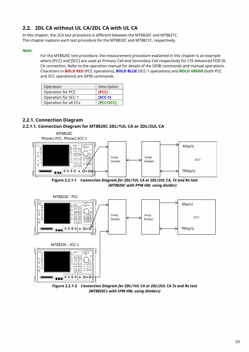
2DL CA without UL CA/2DL CA with UL CA 2.2.In this chapter, the 2CA test procedure is different between the MT8820C and MT8821C. This chapter explains each test procedure for the MT8820C and MT8821C, respectively. Note:
For the MT8820C test procedure, the measurement procedure explained in this chapter is an example where [PCC] and [SCC] are used as Primary Cell and Secondary Cell respectively for LTE-Advanced FDD DL CA connection. Refer to the operation manual for details of the GPIB commands and manual operations. Characters in BOLD RED (PCC operations), BOLD BLUE (SCC-1 operations) and BOLD GREEN (both PCC and SCC operations) are GPIB commands.
Operation Description Operation for PCC [PCC] Operation for SCC-1 [SCC-1] Operation for all CCs [PCC/SCC]
Connection Diagram 2.2.1.2.2.1.1. Connection Diagram for MT8820C 2DL/1UL CA or 2DL/2UL CA
Figure 2.2.1-1 Connection Diagram for 2DL/1UL CA or 2DL/2UL CA, Tx and Rx test
(MT8820C with PPM HW, using divider)
Figure 2.2.1-2 Connection Diagram for 2DL/1UL CA or 2DL/2UL CA Tx and Rx test
(MT8820Cs with SPM HW, using dividers)
53
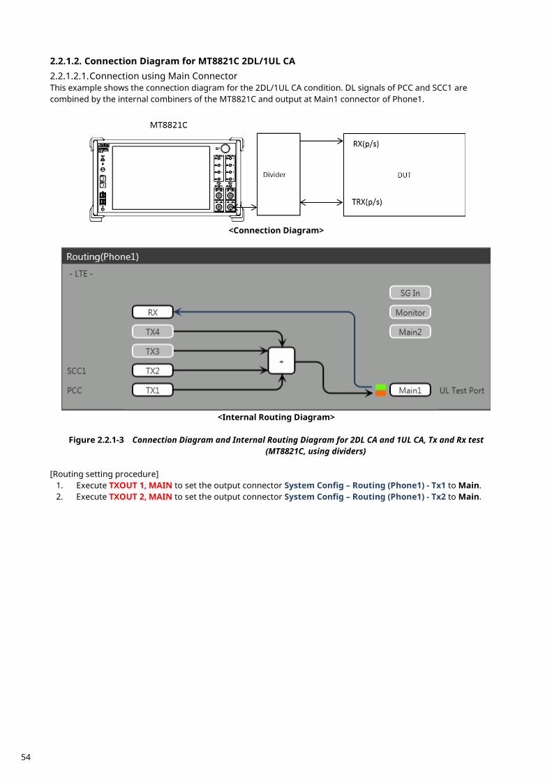
2.2.1.2. Connection Diagram for MT8821C 2DL/1UL CA 2.2.1.2.1. Connection using Main Connector This example shows the connection diagram for the 2DL/1UL CA condition. DL signals of PCC and SCC1 are combined by the internal combiners of the MT8821C and output at Main1 connector of Phone1.
<Connection Diagram>
<Internal Routing Diagram>
Figure 2.2.1-3 Connection Diagram and Internal Routing Diagram for 2DL CA and 1UL CA, Tx and Rx test
(MT8821C, using dividers) [Routing setting procedure]
1. Execute TXOUT 1, MAIN to set the output connector System Config – Routing (Phone1) - Tx1 to Main. 2. Execute TXOUT 2, MAIN to set the output connector System Config – Routing (Phone1) - Tx2 to Main.
54
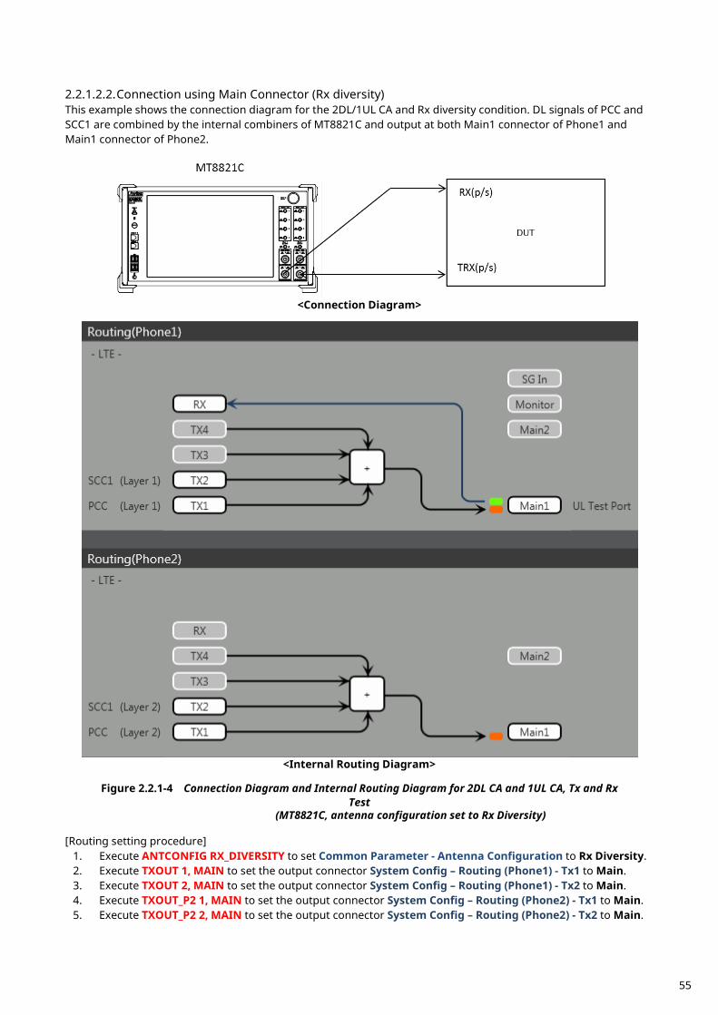
2.2.1.2.2. Connection using Main Connector (Rx diversity) This example shows the connection diagram for the 2DL/1UL CA and Rx diversity condition. DL signals of PCC and SCC1 are combined by the internal combiners of MT8821C and output at both Main1 connector of Phone1 and Main1 connector of Phone2.
<Connection Diagram>
<Internal Routing Diagram>
Figure 2.2.1-4 Connection Diagram and Internal Routing Diagram for 2DL CA and 1UL CA, Tx and Rx
Test (MT8821C, antenna configuration set to Rx Diversity)
[Routing setting procedure]
1. Execute ANTCONFIG RX_DIVERSITY to set Common Parameter - Antenna Configuration to Rx Diversity. 2. Execute TXOUT 1, MAIN to set the output connector System Config – Routing (Phone1) - Tx1 to Main. 3. Execute TXOUT 2, MAIN to set the output connector System Config – Routing (Phone1) - Tx2 to Main. 4. Execute TXOUT_P2 1, MAIN to set the output connector System Config – Routing (Phone2) - Tx1 to Main. 5. Execute TXOUT_P2 2, MAIN to set the output connector System Config – Routing (Phone2) - Tx2 to Main.
55
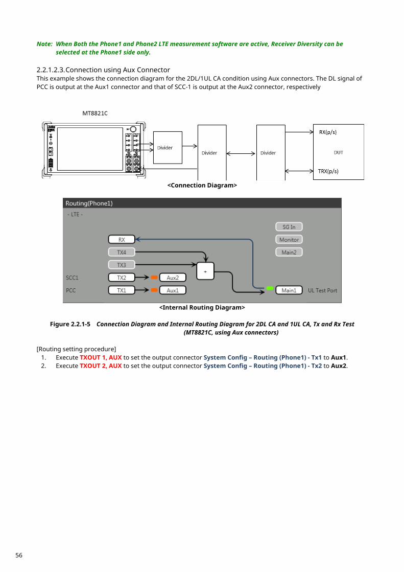
Note: When Both the Phone1 and Phone2 LTE measurement software are active, Receiver Diversity can be selected at the Phone1 side only.
2.2.1.2.3. Connection using Aux Connector This example shows the connection diagram for the 2DL/1UL CA condition using Aux connectors. The DL signal of PCC is output at the Aux1 connector and that of SCC-1 is output at the Aux2 connector, respectively
<Connection Diagram>
<Internal Routing Diagram>
Figure 2.2.1-5 Connection Diagram and Internal Routing Diagram for 2DL CA and 1UL CA, Tx and Rx Test
(MT8821C, using Aux connectors) [Routing setting procedure]
1. Execute TXOUT 1, AUX to set the output connector System Config – Routing (Phone1) - Tx1 to Aux1. 2. Execute TXOUT 2, AUX to set the output connector System Config – Routing (Phone1) - Tx2 to Aux2.
56
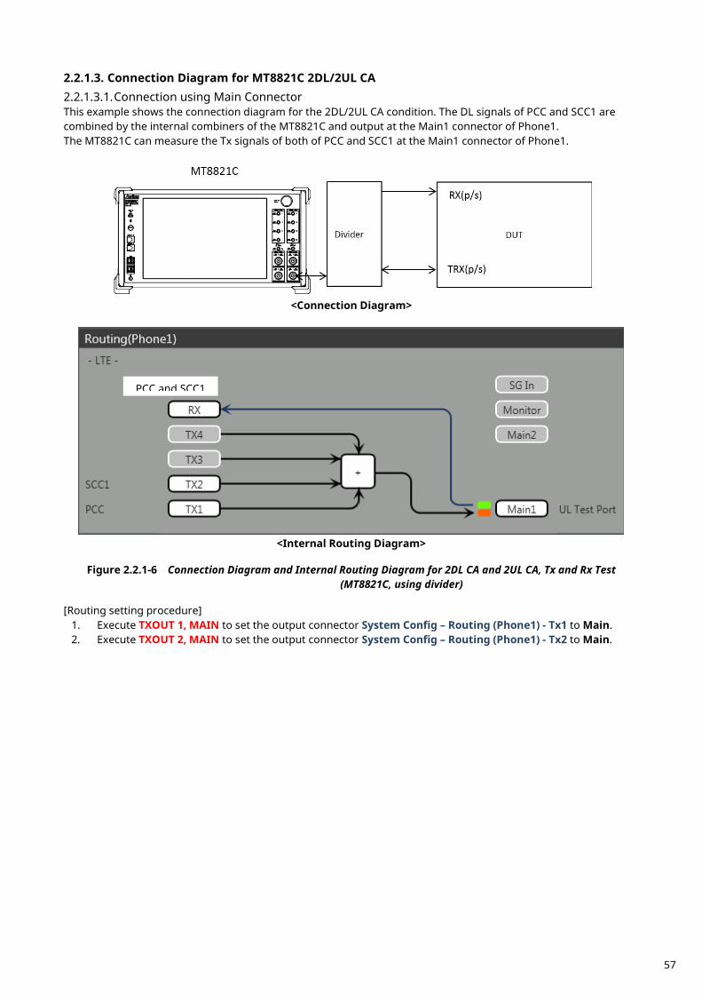
2.2.1.3. Connection Diagram for MT8821C 2DL/2UL CA 2.2.1.3.1. Connection using Main Connector This example shows the connection diagram for the 2DL/2UL CA condition. The DL signals of PCC and SCC1 are combined by the internal combiners of the MT8821C and output at the Main1 connector of Phone1. The MT8821C can measure the Tx signals of both of PCC and SCC1 at the Main1 connector of Phone1.
<Connection Diagram>
<Internal Routing Diagram>
Figure 2.2.1-6 Connection Diagram and Internal Routing Diagram for 2DL CA and 2UL CA, Tx and Rx Test
(MT8821C, using divider) [Routing setting procedure]
1. Execute TXOUT 1, MAIN to set the output connector System Config – Routing (Phone1) - Tx1 to Main. 2. Execute TXOUT 2, MAIN to set the output connector System Config – Routing (Phone1) - Tx2 to Main.
PCC and SCC1
57
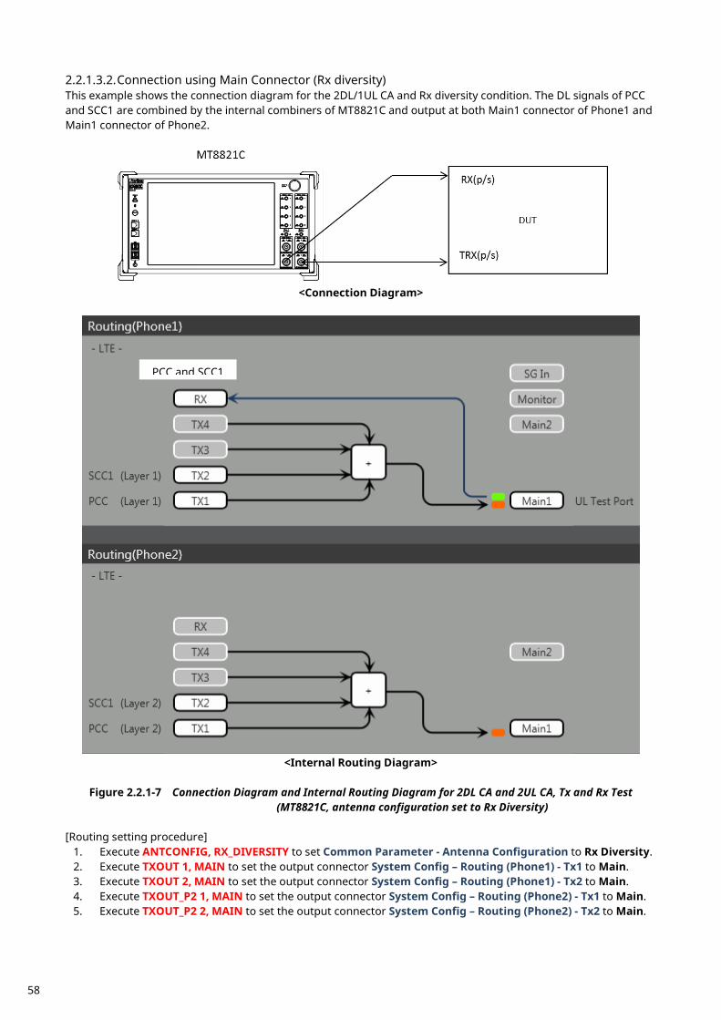
2.2.1.3.2. Connection using Main Connector (Rx diversity) This example shows the connection diagram for the 2DL/1UL CA and Rx diversity condition. The DL signals of PCC and SCC1 are combined by the internal combiners of MT8821C and output at both Main1 connector of Phone1 and Main1 connector of Phone2.
<Connection Diagram>
<Internal Routing Diagram>
Figure 2.2.1-7 Connection Diagram and Internal Routing Diagram for 2DL CA and 2UL CA, Tx and Rx Test
(MT8821C, antenna configuration set to Rx Diversity) [Routing setting procedure]
1. Execute ANTCONFIG, RX_DIVERSITY to set Common Parameter - Antenna Configuration to Rx Diversity. 2. Execute TXOUT 1, MAIN to set the output connector System Config – Routing (Phone1) - Tx1 to Main. 3. Execute TXOUT 2, MAIN to set the output connector System Config – Routing (Phone1) - Tx2 to Main. 4. Execute TXOUT_P2 1, MAIN to set the output connector System Config – Routing (Phone2) - Tx1 to Main. 5. Execute TXOUT_P2 2, MAIN to set the output connector System Config – Routing (Phone2) - Tx2 to Main.
PCC and SCC1
58
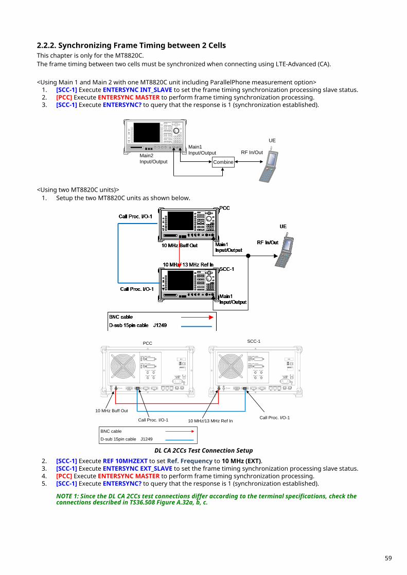
Synchronizing Frame Timing between 2 Cells 2.2.2.This chapter is only for the MT8820C. The frame timing between two cells must be synchronized when connecting using LTE-Advanced (CA). <Using Main 1 and Main 2 with one MT8820C unit including ParallelPhone measurement option>
1. [SCC-1] Execute ENTERSYNC INT_SLAVE to set the frame timing synchronization processing slave status. 2. [PCC] Execute ENTERSYNC MASTER to perform frame timing synchronization processing. 3. [SCC-1] Execute ENTERSYNC? to query that the response is 1 (synchronization established).
Main2 Input/Output
RF In/Out
UE
Combine
Main1 Input/Output
<Using two MT8820C units)>
1. Setup the two MT8820C units as shown below.
Call Proc. I/O-1 Call Proc. I/O-1 10 MHz Buff Out
10 MHz/13 MHz Ref In
PCC
SCC-1
BNC cable
D-sub 15pin cable J1249
DL CA 2CCs Test Connection Setup 2. [SCC-1] Execute REF 10MHZEXT to set Ref. Frequency to 10 MHz (EXT). 3. [SCC-1] Execute ENTERSYNC EXT_SLAVE to set the frame timing synchronization processing slave status. 4. [PCC] Execute ENTERSYNC MASTER to perform frame timing synchronization processing. 5. [SCC-1] Execute ENTERSYNC? to query that the response is 1 (synchronization established).
NOTE 1: Since the DL CA 2CCs test connections differ according to the terminal specifications, check the connections described in TS36.508 Figure A.32a, b, c.
59
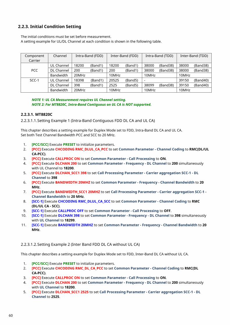
Initial Condition Setting 2.2.3. The initial conditions must be set before measurement. A setting example for UL/DL Channel at each condition is shown in the following table.
Component Carrier
Channel Intra-Band (FDD) Inter-Band (FDD) Intra-Band (TDD) Inter-Band (TDD)
PCC UL Channel 18200 (Band1) 18200 (Band1) 38000 (Band38) 38000 (Band38) DL Channel 200 (Band1) 200 (Band1) 38000 (Band38) 38000 (Band38) Bandwidth 20MHz 10MHz 10MHz 10MHz
SCC-1 UL Channel 18398 (Band1) 20525 (Band5) - 39150 (Band40) DL Channel 398 (Band1) 2525 (Band5) 38099 (Band38) 39150 (Band40) Bandwidth 20MHz 10MHz 10MHz 10MHz
NOTE 1: UL CA Measurement requires UL Channel setting. NOTE 2: For MT8820C, Intra-Band Contiguous on UL CA is NOT supported.
2.2.3.1. MT8820C 2.2.3.1.1. Setting Example 1 (Intra-Band Contiguous FDD DL CA and UL CA) This chapter describes a setting example for Duplex Mode set to FDD, Intra-Band DL CA and UL CA. Set both Test Channel Bandwidth PCC and SCC to 20 MHz.
1. [PCC/SCC] Execute PRESET to initialize parameters. 2. [PCC] Execute CHCODING RMC_DLUL_CA_PCC to set Common Parameter - Channel Coding to RMC(DL/UL
CA-PCC). 3. [PCC] Execute CALLPROC ON to set Common Parameter - Call Processing to ON. 4. [PCC] Execute DLCHAN 200 to set Common Parameter - Frequency - DL Channel to 200 simultaneously
with UL Channel to 18200. 5. [PCC] Execute DLCHAN_SCC1 398 to set Call Processing Parameter - Carrier aggregation SCC-1 - DL
Channel to 398 6. [PCC] Execute BANDWIDTH 20MHZ to set Common Parameter - Frequency - Channel Bandwidth to 20
MHz. 7. [PCC] Execute BANDWIDTH_SCC1 20MHZ to set Call Processing Parameter - Carrier aggregation SCC-1 -
Channel Bandwidth to 20 MHz. 8. [SCC-1] Execute CHCODING RMC_DLUL_CA_SCC to set Common Parameter - Channel Coding to RMC
(DL/UL CA - SCC). 9. [SCC-1] Execute CALLPROC OFF to set Common Parameter - Call Processing to OFF.
10. [SCC-1] Execute DLCHAN 398 to set Common Parameter - Frequency - DL Channel to 398 simultaneously with UL Channel to 18299.
11. [SCC-1] Execute BANDWIDTH 20MHZ to set Common Parameter - Frequency - Channel Bandwidth to 20 MHz.
2.2.3.1.2. Setting Example 2 (Inter Band FDD DL CA without UL CA) This chapter describes a setting example for Duplex Mode set to FDD, Inter-Band DL CA without UL CA.
1. [PCC/SCC] Execute PRESET to initialize parameters. 2. [PCC] Execute CHCODING RMC_DL_CA_PCC to set Common Parameter - Channel Coding to RMC(DL
CA-PCC). 3. [PCC] Execute CALLPROC ON to set Common Parameter - Call Processing to ON. 4. [PCC] Execute DLCHAN 200 to set Common Parameter - Frequency - DL Channel to 200 simultaneously
with UL Channel to 18200. 5. [PCC] Execute DLCHAN_SCC1 2525 to set Call Processing Parameter - Carrier aggregation SCC-1 - DL
Channel to 2525.
60
6. [PCC] Execute BANDWIDTH 10MHZ to set Common Parameter - Frequency - Channel Bandwidth to 10 MHz.
7. [PCC] Execute BANDWIDTH_SCC1 10MHZ to set Call Processing Parameter - Carrier aggregation SCC-1 - Channel Bandwidth to 10 MHz.
8. [SCC-1] Execute CHCODING RMC_DLUL_CA_SCC to set Common Parameter - Channel Coding to RMC (DL/UL CA - SCC).
9. [SCC-1] Execute CALLPROC OFF to set Common Parameter - Call Processing to OFF. 10. [SCC-1] Execute DLCHAN 2525 to set Common Parameter - Frequency - DL Channel to 2525. 11. [SCC-1] Execute BANDWIDTH 10MHZ to set Common Parameter - Frequency - Channel Bandwidth to 10
MHz. 2.2.3.1.3. Setting Example 3 (Intra-Band TDD DL CA without UL CA) This chapter describes a setting example for Duplex Mode set to TDD, Intra-Band DL CA without UL CA. The Uplink/Downlink Configuration is set to 1, and Special Subframe Configuration is set to 4. Follow the procedure in Chapter 2.2.3.1.2 replacing Step 4, 5, 10 and 11, followed by Step 14 and 15 as below.
4. [PCC] Execute DLCHAN 38000 to set Common Parameter - Frequency - DLChannel simultaneously with UL Channel to 38000.
5. [PCC] Execute DLCHAN_SCC1 38099 to set Call Processing Parameter - Carrier aggregation SCC-1 - DL Channel to 38099.
10. [SCC-1] Execute ULCHAN_PCC 38000 to set Call Processing Parameter - Carrier aggregation PCC - UL
Channel to 38000. 11. [SCC-1] Execute DLCHAN 38099 to set Common Parameter – Frequency - DL Channel to 38099. 14. [PCC/SCC] Execute TDDULDLCONF 1 to set Common Parameter - TDD Uplink/Downlink Configuration to
1. 15. [PCC/SCC] Execute TDDSSFCONF 4 to set Common Parameter - TDD Special Subframe Configuration to 4.
NOTE 1: Set same value as Uplink/Downlink Configuration in PCC and SCC. NOTE 2: Set same value as Special Subframe Configuration in PCC and SCC.
2.2.3.1.4. Setting Example 4 (Inter-Band TDD DL CA and UL CA) This chapter describes a setting example for Duplex Mode set to TDD, Inter-Band DL CA and UL CA The Uplink/Downlink Configuration is set to 2, and Special Subframe Configuration is set to 5. Follow the procedure in Chapter 2.2.3.1.1 replacing with Step 4, 5, 10 and 11, followed by Step 12 and 13 as below.
4. [PCC] Execute DLCHAN 38000 to set Common Parameter - Frequency - DL Channel simultaneously with UL Channel to 38000.
5. [PCC] Execute DLCHAN_SCC1 39150 to set Call Processing Parameter - Carrier aggregation SCC-1 - DL Channel to 39150.
10. [SCC-1] Execute DLCHAN 39150 to set Common Parameter - Frequency - DL Channel simultaneously with UL Channel to 39150.
12. [PCC/SCC] Execute TDDULDLCONF 2 to set Common Parameter - TDD Uplink/Downlink Configuration to
2. 13. [PCC/SCC] Execute TDDSSFCONF 5 to set Common Parameter - TDD Special Subframe Configuration to 5.
NOTE 1: Set same value as Uplink/Downlink Configuration in PCC and SCC. NOTE 2: Set same value as Special Subframe Configuration in PCC and SCC.
61
2.2.3.1.5. Setting Example 5 (FDD-TDD DL CA without UL CA for PCell FDD) This chapter describes a setting example for PCC Duplex Mode set to FDD, SCC Duplex Mode set to TDD, DL CA without UL CA. The SCC Uplink/Downlink Configuration is set to 2, and Special Subframe Configuration is set to 5.
1. [PCC/SCC] Execute PRESET to initialize parameters. 2. [PCC] Execute CHCODING RMC_DLUL_CA_PCC to set Common Parameter - Channel Coding to RMC(DL/UL
CA-PCC). 3. [PCC] Execute CALLPROC ON to set Common Parameter - Call Processing to ON. 4. [PCC] Execute DLCHAN 200 to set Common Parameter - Frequency - DL Channel to 200 simultaneously
with UL Channel to 18200. 5. [PCC] Execute DLCHAN_SCC1 38000 to set Call Processing Parameter - Carrier aggregation SCC-1 - DL
Channel to 38000 6. [PCC] Execute BANDWIDTH 10MHZ to set Common Parameter - Frequency - Channel Bandwidth to 10
MHz. 7. [PCC] Execute BANDWIDTH_SCC1 10MHZ to set Call Processing Parameter - Carrier aggregation SCC-1 -
Channel Bandwidth to 10 MHz. 8. [PCC] Execute TDDULDLCONF_SCC1 2 to set Call Processing Parameter - Carrier aggregation SCC-1 - TDD
Uplink/Downlink Configuration to 2. 9. [PCC] Execute TDDSSFCONF_SCC1 5 to set Call Processing Parameter - Carrier aggregation SCC-1 - TDD
Special Subframe Configuration to 5. 10. [SCC-1] Execute CHCODING RMC_DLUL_CA_SCC to set Common Parameter - Channel Coding to RMC
(DL/UL CA - SCC). 11. [SCC-1] Execute CALLPROC OFF to set Common Parameter - Call Processing to OFF. 12. [SCC-1] Execute DLCHAN 38000 to set Common Parameter - Frequency - DL Channel to 38000. 13. [SCC-1] Execute BANDWIDTH 10MHZ to set Common Parameter - Frequency - Channel Bandwidth to 10
MHz. 14. [SCC-1] Execute ULCHAN_PCC 18200 to set Call Processing Parameter - Carrier aggregation PCC - UL
Channel to 18200. 2.2.3.1.6. Setting Example 6 (FDD-TDD DL CA without UL CA for PCell TDD) This chapter describes a setting example for PCC Duplex Mode set to TDD, SCC Duplex Mode set to FDD, DL CA without UL CA. PCC supports only Uplink/Downlink Configuration 1.
1. [PCC/SCC] Execute PRESET to initialize parameters. 2. [PCC] Execute CHCODING RMC_DLUL_CA_PCC to set Common Parameter - Channel Coding to RMC(DL/UL
CA-PCC). 3. [PCC] Execute CALLPROC ON to set Common Parameter - Call Processing to ON. 4. [PCC] Execute DLCHAN 38000 to set Common Parameter - Frequency - DL Channel simultaneously with
UL Channel to 38000. 5. [PCC] Execute DLCHAN_SCC1 200 to set Call Processing Parameter - Carrier aggregation SCC-1 - DL
Channel to 200 6. [PCC] Execute BANDWIDTH 10MHZ to set Common Parameter - Frequency - Channel Bandwidth to 10
MHz. 7. [PCC] Execute BANDWIDTH_SCC1 10MHZ to set Call Processing Parameter - Carrier aggregation SCC-1 -
Channel Bandwidth to 10 MHz. 8. [PCC] Execute TDDULDLCONF 1 to set Common Parameter - TDD Uplink/Downlink Configuration to 1. 9. [PCC] Execute TDDSSFCONF 4 to set Common Parameter - TDD Special Subframe Configuration to 4.
10. [SCC-1] Execute CHCODING RMC_DLUL_CA_SCC to set Common Parameter - Channel Coding to RMC (DL/UL CA - SCC).
11. [SCC-1] Execute CALLPROC OFF to set Common Parameter - Call Processing to OFF. 12. [SCC-1] Execute DLCHAN 200 to set Common Parameter - Frequency - DL Channel to 200. 13. [SCC-1] Execute BANDWIDTH 10MHZ to set Common Parameter - Frequency - Channel Bandwidth to 10
MHz. 14. [SCC-1] Execute ULCHAN_PCC 38000 to set Call Processing Parameter - Carrier aggregation PCC - UL
Channel to 38000. 15. [SCC-1] Execute TDDULDLCONF_PCC 1 to set Call Processing Parameter - Carrier aggregation PCC - TDD
Uplink/Downlink Configuration to 1.
62
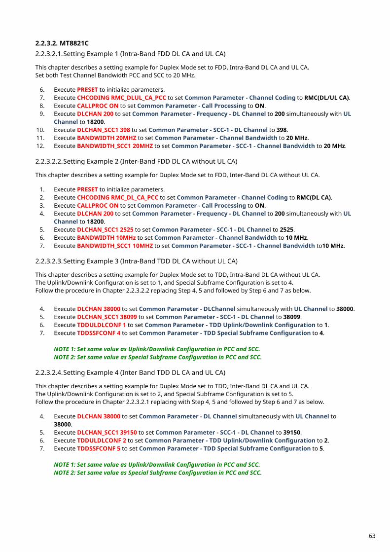
2.2.3.2. MT8821C 2.2.3.2.1. Setting Example 1 (Intra-Band FDD DL CA and UL CA) This chapter describes a setting example for Duplex Mode set to FDD, Intra-Band DL CA and UL CA. Set both Test Channel Bandwidth PCC and SCC to 20 MHz.
6. Execute PRESET to initialize parameters. 7. Execute CHCODING RMC_DLUL_CA_PCC to set Common Parameter - Channel Coding to RMC(DL/UL CA). 8. Execute CALLPROC ON to set Common Parameter - Call Processing to ON. 9. Execute DLCHAN 200 to set Common Parameter - Frequency - DL Channel to 200 simultaneously with UL
Channel to 18200. 10. Execute DLCHAN_SCC1 398 to set Common Parameter - SCC-1 - DL Channel to 398. 11. Execute BANDWIDTH 20MHZ to set Common Parameter - Channel Bandwidth to 20 MHz. 12. Execute BANDWIDTH_SCC1 20MHZ to set Common Parameter - SCC-1 - Channel Bandwidth to 20 MHz. 2.2.3.2.2. Setting Example 2 (Inter-Band FDD DL CA without UL CA) This chapter describes a setting example for Duplex Mode set to FDD, Inter-Band DL CA without UL CA.
1. Execute PRESET to initialize parameters. 2. Execute CHCODING RMC_DL_CA_PCC to set Common Parameter - Channel Coding to RMC(DL CA). 3. Execute CALLPROC ON to set Common Parameter - Call Processing to ON. 4. Execute DLCHAN 200 to set Common Parameter - Frequency - DL Channel to 200 simultaneously with UL
Channel to 18200. 5. Execute DLCHAN_SCC1 2525 to set Common Parameter - SCC-1 - DL Channel to 2525. 6. Execute BANDWIDTH 10MHz to set Common Parameter - Channel Bandwidth to 10 MHz. 7. Execute BANDWIDTH_SCC1 10MHZ to set Common Parameter - SCC-1 - Channel Bandwidth to10 MHz.
2.2.3.2.3. Setting Example 3 (Intra-Band TDD DL CA without UL CA) This chapter describes a setting example for Duplex Mode set to TDD, Intra-Band DL CA without UL CA. The Uplink/Downlink Configuration is set to 1, and Special Subframe Configuration is set to 4. Follow the procedure in Chapter 2.2.3.2.2 replacing Step 4, 5 and followed by Step 6 and 7 as below.
4. Execute DLCHAN 38000 to set Common Parameter - DLChannel simultaneously with UL Channel to 38000. 5. Execute DLCHAN_SCC1 38099 to set Common Parameter - SCC-1 - DL Channel to 38099. 6. Execute TDDULDLCONF 1 to set Common Parameter - TDD Uplink/Downlink Configuration to 1. 7. Execute TDDSSFCONF 4 to set Common Parameter - TDD Special Subframe Configuration to 4.
NOTE 1: Set same value as Uplink/Downlink Configuration in PCC and SCC. NOTE 2: Set same value as Special Subframe Configuration in PCC and SCC.
2.2.3.2.4. Setting Example 4 (Inter Band TDD DL CA and UL CA) This chapter describes a setting example for Duplex Mode set to TDD, Inter-Band DL CA and UL CA. The Uplink/Downlink Configuration is set to 2, and Special Subframe Configuration is set to 5. Follow the procedure in Chapter 2.2.3.2.1 replacing with Step 4, 5 and followed by Step 6 and 7 as below.
4. Execute DLCHAN 38000 to set Common Parameter - DL Channel simultaneously with UL Channel to 38000.
5. Execute DLCHAN_SCC1 39150 to set Common Parameter - SCC-1 - DL Channel to 39150. 6. Execute TDDULDLCONF 2 to set Common Parameter - TDD Uplink/Downlink Configuration to 2. 7. Execute TDDSSFCONF 5 to set Common Parameter - TDD Special Subframe Configuration to 5.
NOTE 1: Set same value as Uplink/Downlink Configuration in PCC and SCC. NOTE 2: Set same value as Special Subframe Configuration in PCC and SCC.
63
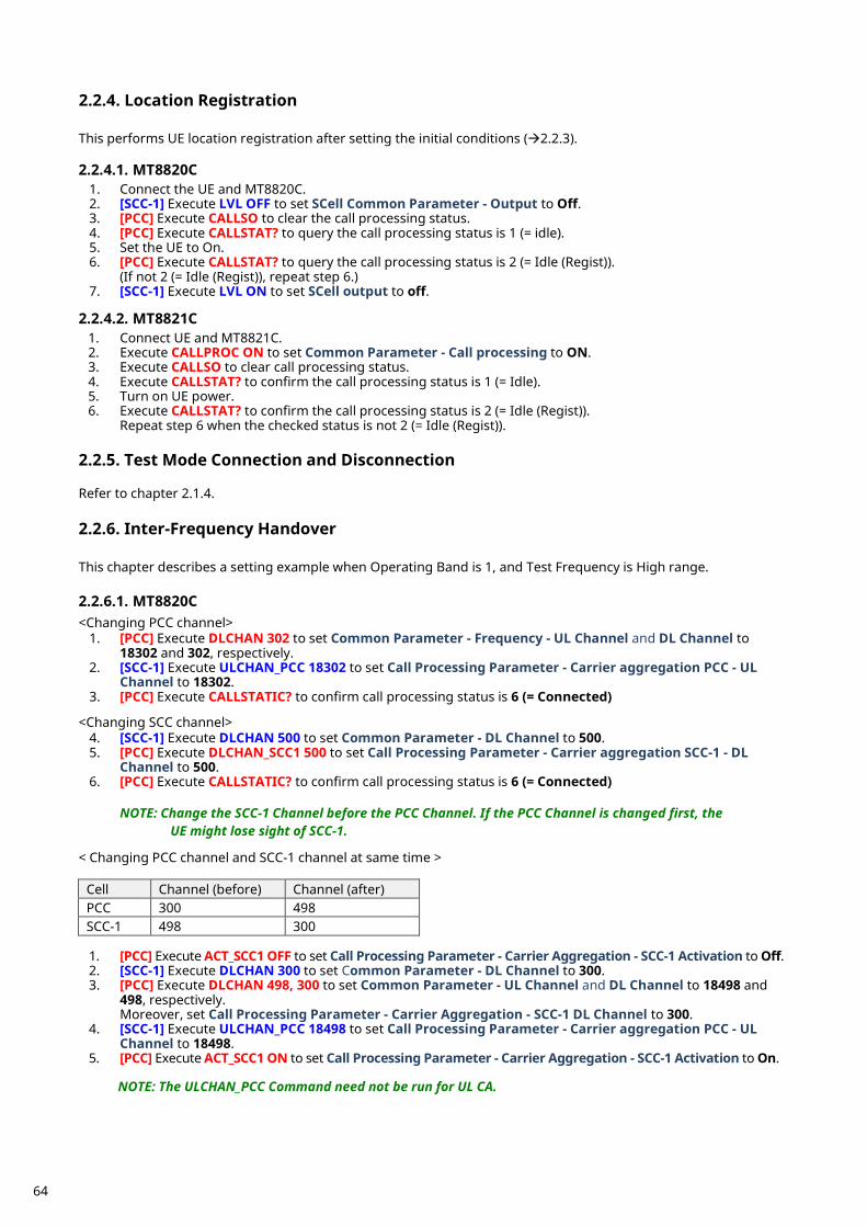
Location Registration 2.2.4. This performs UE location registration after setting the initial conditions (2.2.3). 2.2.4.1. MT8820C
1. Connect the UE and MT8820C. 2. [SCC-1] Execute LVL OFF to set SCell Common Parameter - Output to Off. 3. [PCC] Execute CALLSO to clear the call processing status. 4. [PCC] Execute CALLSTAT? to query the call processing status is 1 (= idle). 5. Set the UE to On. 6. [PCC] Execute CALLSTAT? to query the call processing status is 2 (= Idle (Regist)).
(If not 2 (= Idle (Regist)), repeat step 6.) 7. [SCC-1] Execute LVL ON to set SCell output to off.
2.2.4.2. MT8821C
1. Connect UE and MT8821C. 2. Execute CALLPROC ON to set Common Parameter - Call processing to ON. 3. Execute CALLSO to clear call processing status. 4. Execute CALLSTAT? to confirm the call processing status is 1 (= Idle). 5. Turn on UE power. 6. Execute CALLSTAT? to confirm the call processing status is 2 (= Idle (Regist)).
Repeat step 6 when the checked status is not 2 (= Idle (Regist)).
Test Mode Connection and Disconnection 2.2.5. Refer to chapter 2.1.4.
Inter-Frequency Handover 2.2.6. This chapter describes a setting example when Operating Band is 1, and Test Frequency is High range. 2.2.6.1. MT8820C <Changing PCC channel>
1. [PCC] Execute DLCHAN 302 to set Common Parameter - Frequency - UL Channel and DL Channel to 18302 and 302, respectively.
2. [SCC-1] Execute ULCHAN_PCC 18302 to set Call Processing Parameter - Carrier aggregation PCC - UL Channel to 18302.
3. [PCC] Execute CALLSTATIC? to confirm call processing status is 6 (= Connected) <Changing SCC channel>
4. [SCC-1] Execute DLCHAN 500 to set Common Parameter - DL Channel to 500. 5. [PCC] Execute DLCHAN_SCC1 500 to set Call Processing Parameter - Carrier aggregation SCC-1 - DL
Channel to 500. 6. [PCC] Execute CALLSTATIC? to confirm call processing status is 6 (= Connected)
NOTE: Change the SCC-1 Channel before the PCC Channel. If the PCC Channel is changed first, the
UE might lose sight of SCC-1. < Changing PCC channel and SCC-1 channel at same time >
Cell Channel (before) Channel (after) PCC 300 498 SCC-1 498 300
1. [PCC] Execute ACT_SCC1 OFF to set Call Processing Parameter - Carrier Aggregation - SCC-1 Activation to Off. 2. [SCC-1] Execute DLCHAN 300 to set Common Parameter - DL Channel to 300. 3. [PCC] Execute DLCHAN 498, 300 to set Common Parameter - UL Channel and DL Channel to 18498 and
498, respectively. Moreover, set Call Processing Parameter - Carrier Aggregation - SCC-1 DL Channel to 300.
4. [SCC-1] Execute ULCHAN_PCC 18498 to set Call Processing Parameter - Carrier aggregation PCC - UL Channel to 18498.
5. [PCC] Execute ACT_SCC1 ON to set Call Processing Parameter - Carrier Aggregation - SCC-1 Activation to On.
NOTE: The ULCHAN_PCC Command need not be run for UL CA.
64
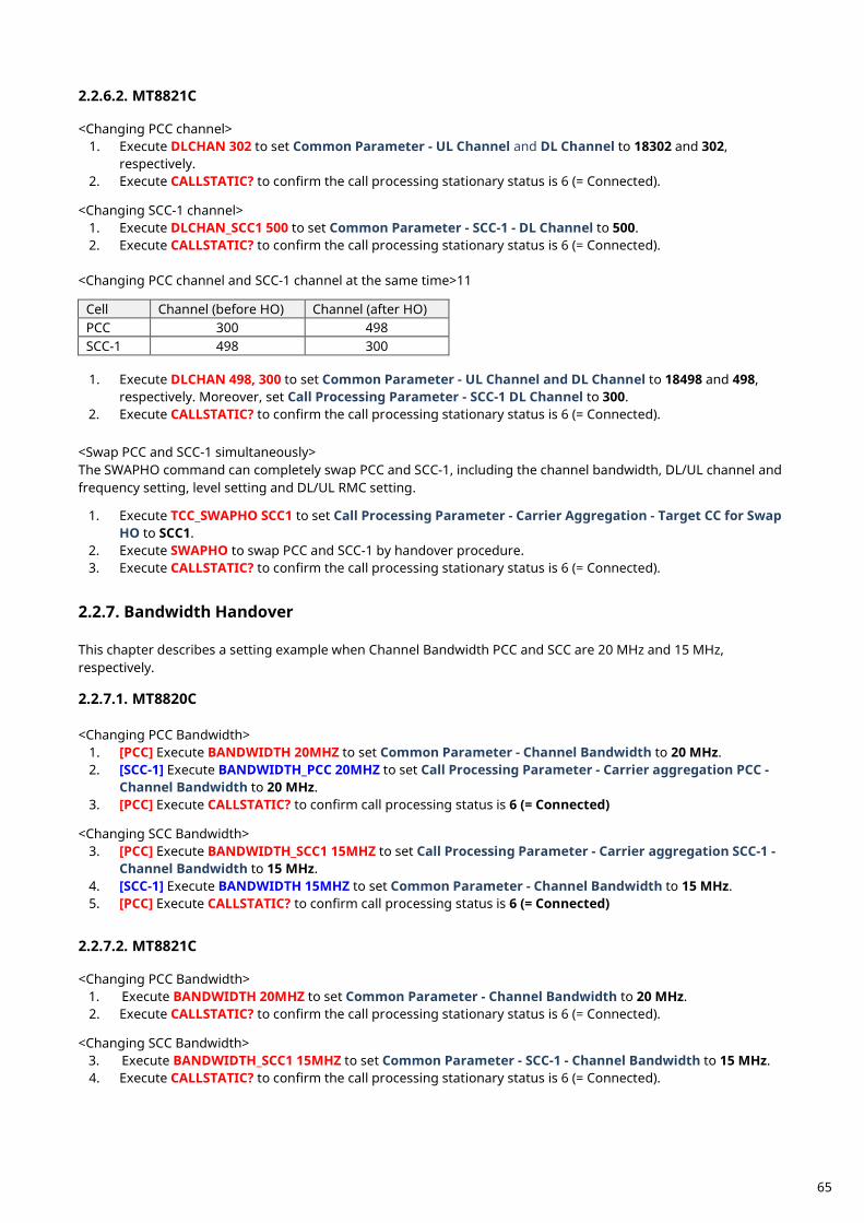
2.2.6.2. MT8821C <Changing PCC channel>
1. Execute DLCHAN 302 to set Common Parameter - UL Channel and DL Channel to 18302 and 302, respectively.
2. Execute CALLSTATIC? to confirm the call processing stationary status is 6 (= Connected). <Changing SCC-1 channel>
1. Execute DLCHAN_SCC1 500 to set Common Parameter - SCC-1 - DL Channel to 500. 2. Execute CALLSTATIC? to confirm the call processing stationary status is 6 (= Connected).
<Changing PCC channel and SCC-1 channel at the same time>11
Cell Channel (before HO) Channel (after HO) PCC 300 498 SCC-1 498 300
1. Execute DLCHAN 498, 300 to set Common Parameter - UL Channel and DL Channel to 18498 and 498,
respectively. Moreover, set Call Processing Parameter - SCC-1 DL Channel to 300. 2. Execute CALLSTATIC? to confirm the call processing stationary status is 6 (= Connected).
<Swap PCC and SCC-1 simultaneously> The SWAPHO command can completely swap PCC and SCC-1, including the channel bandwidth, DL/UL channel and frequency setting, level setting and DL/UL RMC setting.
1. Execute TCC_SWAPHO SCC1 to set Call Processing Parameter - Carrier Aggregation - Target CC for Swap HO to SCC1.
2. Execute SWAPHO to swap PCC and SCC-1 by handover procedure. 3. Execute CALLSTATIC? to confirm the call processing stationary status is 6 (= Connected).
Bandwidth Handover 2.2.7. This chapter describes a setting example when Channel Bandwidth PCC and SCC are 20 MHz and 15 MHz, respectively. 2.2.7.1. MT8820C <Changing PCC Bandwidth>
1. [PCC] Execute BANDWIDTH 20MHZ to set Common Parameter - Channel Bandwidth to 20 MHz. 2. [SCC-1] Execute BANDWIDTH_PCC 20MHZ to set Call Processing Parameter - Carrier aggregation PCC -
Channel Bandwidth to 20 MHz. 3. [PCC] Execute CALLSTATIC? to confirm call processing status is 6 (= Connected)
<Changing SCC Bandwidth>
3. [PCC] Execute BANDWIDTH_SCC1 15MHZ to set Call Processing Parameter - Carrier aggregation SCC-1 - Channel Bandwidth to 15 MHz.
4. [SCC-1] Execute BANDWIDTH 15MHZ to set Common Parameter - Channel Bandwidth to 15 MHz. 5. [PCC] Execute CALLSTATIC? to confirm call processing status is 6 (= Connected)
2.2.7.2. MT8821C <Changing PCC Bandwidth>
1. Execute BANDWIDTH 20MHZ to set Common Parameter - Channel Bandwidth to 20 MHz. 2. Execute CALLSTATIC? to confirm the call processing stationary status is 6 (= Connected).
<Changing SCC Bandwidth>
3. Execute BANDWIDTH_SCC1 15MHZ to set Common Parameter - SCC-1 - Channel Bandwidth to 15 MHz. 4. Execute CALLSTATIC? to confirm the call processing stationary status is 6 (= Connected).
65
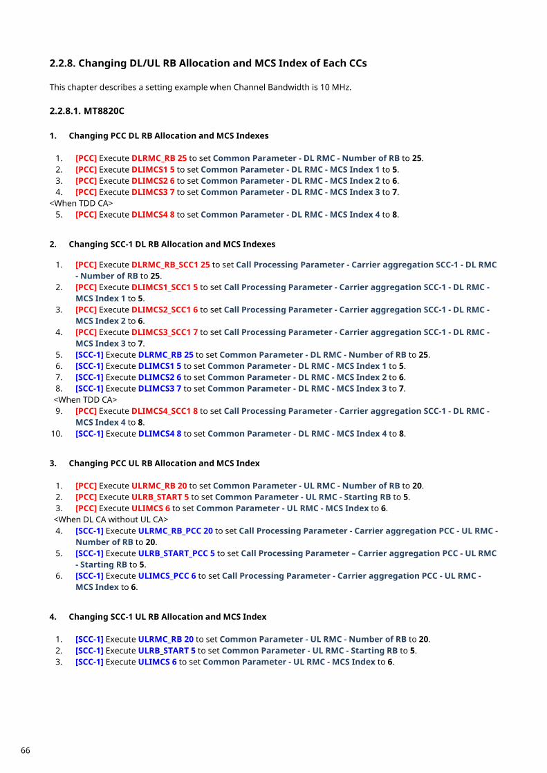
Changing DL/UL RB Allocation and MCS Index of Each CCs 2.2.8. This chapter describes a setting example when Channel Bandwidth is 10 MHz. 2.2.8.1. MT8820C 1. Changing PCC DL RB Allocation and MCS Indexes
1. [PCC] Execute DLRMC_RB 25 to set Common Parameter - DL RMC - Number of RB to 25. 2. [PCC] Execute DLIMCS1 5 to set Common Parameter - DL RMC - MCS Index 1 to 5. 3. [PCC] Execute DLIMCS2 6 to set Common Parameter - DL RMC - MCS Index 2 to 6. 4. [PCC] Execute DLIMCS3 7 to set Common Parameter - DL RMC - MCS Index 3 to 7.
<When TDD CA> 5. [PCC] Execute DLIMCS4 8 to set Common Parameter - DL RMC - MCS Index 4 to 8.
2. Changing SCC-1 DL RB Allocation and MCS Indexes
1. [PCC] Execute DLRMC_RB_SCC1 25 to set Call Processing Parameter - Carrier aggregation SCC-1 - DL RMC - Number of RB to 25.
2. [PCC] Execute DLIMCS1_SCC1 5 to set Call Processing Parameter - Carrier aggregation SCC-1 - DL RMC - MCS Index 1 to 5.
3. [PCC] Execute DLIMCS2_SCC1 6 to set Call Processing Parameter - Carrier aggregation SCC-1 - DL RMC - MCS Index 2 to 6.
4. [PCC] Execute DLIMCS3_SCC1 7 to set Call Processing Parameter - Carrier aggregation SCC-1 - DL RMC - MCS Index 3 to 7.
5. [SCC-1] Execute DLRMC_RB 25 to set Common Parameter - DL RMC - Number of RB to 25. 6. [SCC-1] Execute DLIMCS1 5 to set Common Parameter - DL RMC - MCS Index 1 to 5. 7. [SCC-1] Execute DLIMCS2 6 to set Common Parameter - DL RMC - MCS Index 2 to 6. 8. [SCC-1] Execute DLIMCS3 7 to set Common Parameter - DL RMC - MCS Index 3 to 7. <When TDD CA> 9. [PCC] Execute DLIMCS4_SCC1 8 to set Call Processing Parameter - Carrier aggregation SCC-1 - DL RMC -
MCS Index 4 to 8. 10. [SCC-1] Execute DLIMCS4 8 to set Common Parameter - DL RMC - MCS Index 4 to 8. 3. Changing PCC UL RB Allocation and MCS Index
1. [PCC] Execute ULRMC_RB 20 to set Common Parameter - UL RMC - Number of RB to 20. 2. [PCC] Execute ULRB_START 5 to set Common Parameter - UL RMC - Starting RB to 5. 3. [PCC] Execute ULIMCS 6 to set Common Parameter - UL RMC - MCS Index to 6. <When DL CA without UL CA> 4. [SCC-1] Execute ULRMC_RB_PCC 20 to set Call Processing Parameter - Carrier aggregation PCC - UL RMC -
Number of RB to 20. 5. [SCC-1] Execute ULRB_START_PCC 5 to set Call Processing Parameter – Carrier aggregation PCC - UL RMC
- Starting RB to 5. 6. [SCC-1] Execute ULIMCS_PCC 6 to set Call Processing Parameter - Carrier aggregation PCC - UL RMC -
MCS Index to 6. 4. Changing SCC-1 UL RB Allocation and MCS Index
1. [SCC-1] Execute ULRMC_RB 20 to set Common Parameter - UL RMC - Number of RB to 20. 2. [SCC-1] Execute ULRB_START 5 to set Common Parameter - UL RMC - Starting RB to 5. 3. [SCC-1] Execute ULIMCS 6 to set Common Parameter - UL RMC - MCS Index to 6.
66
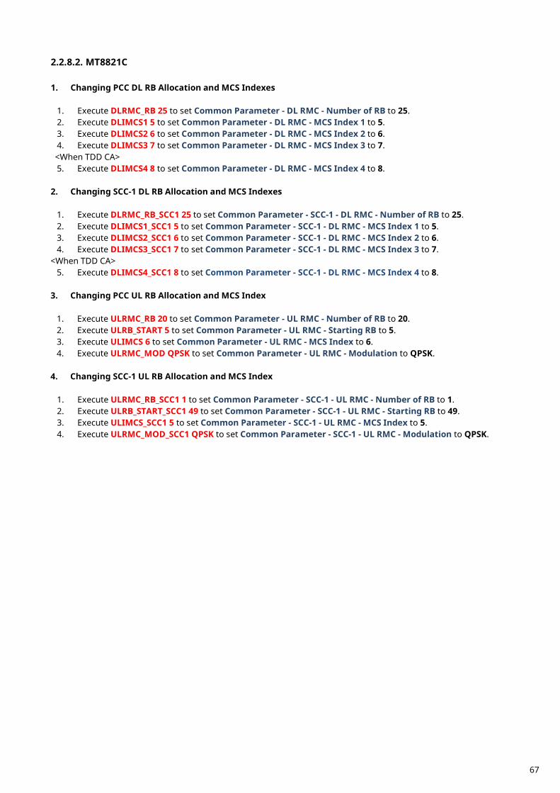
2.2.8.2. MT8821C 1. Changing PCC DL RB Allocation and MCS Indexes
1. Execute DLRMC_RB 25 to set Common Parameter - DL RMC - Number of RB to 25. 2. Execute DLIMCS1 5 to set Common Parameter - DL RMC - MCS Index 1 to 5. 3. Execute DLIMCS2 6 to set Common Parameter - DL RMC - MCS Index 2 to 6. 4. Execute DLIMCS3 7 to set Common Parameter - DL RMC - MCS Index 3 to 7. <When TDD CA> 5. Execute DLIMCS4 8 to set Common Parameter - DL RMC - MCS Index 4 to 8.
2. Changing SCC-1 DL RB Allocation and MCS Indexes
1. Execute DLRMC_RB_SCC1 25 to set Common Parameter - SCC-1 - DL RMC - Number of RB to 25. 2. Execute DLIMCS1_SCC1 5 to set Common Parameter - SCC-1 - DL RMC - MCS Index 1 to 5. 3. Execute DLIMCS2_SCC1 6 to set Common Parameter - SCC-1 - DL RMC - MCS Index 2 to 6. 4. Execute DLIMCS3_SCC1 7 to set Common Parameter - SCC-1 - DL RMC - MCS Index 3 to 7.
<When TDD CA> 5. Execute DLIMCS4_SCC1 8 to set Common Parameter - SCC-1 - DL RMC - MCS Index 4 to 8.
3. Changing PCC UL RB Allocation and MCS Index
1. Execute ULRMC_RB 20 to set Common Parameter - UL RMC - Number of RB to 20. 2. Execute ULRB_START 5 to set Common Parameter - UL RMC - Starting RB to 5. 3. Execute ULIMCS 6 to set Common Parameter - UL RMC - MCS Index to 6. 4. Execute ULRMC_MOD QPSK to set Common Parameter - UL RMC - Modulation to QPSK.
4. Changing SCC-1 UL RB Allocation and MCS Index
1. Execute ULRMC_RB_SCC1 1 to set Common Parameter - SCC-1 - UL RMC - Number of RB to 1. 2. Execute ULRB_START_SCC1 49 to set Common Parameter - SCC-1 - UL RMC - Starting RB to 49. 3. Execute ULIMCS_SCC1 5 to set Common Parameter - SCC-1 - UL RMC - MCS Index to 5. 4. Execute ULRMC_MOD_SCC1 QPSK to set Common Parameter - SCC-1 - UL RMC - Modulation to QPSK.
67
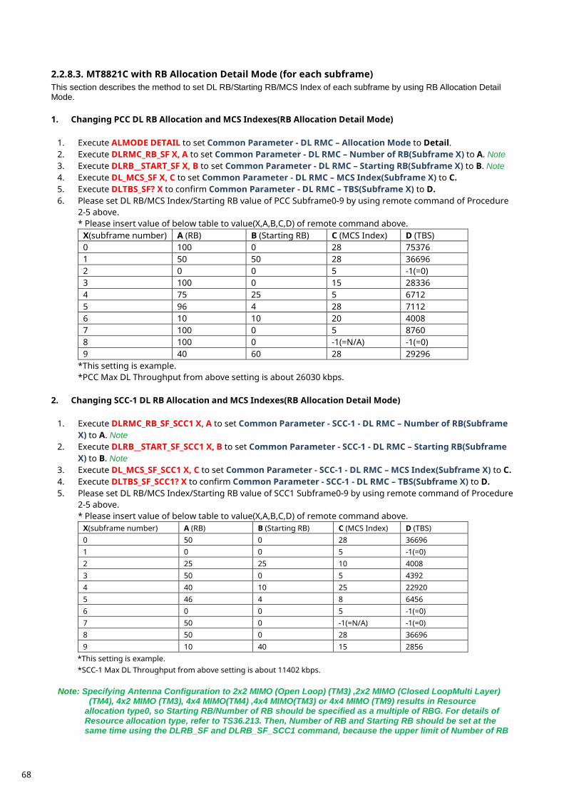
2.2.8.3. MT8821C with RB Allocation Detail Mode (for each subframe) This section describes the method to set DL RB/Starting RB/MCS Index of each subframe by using RB Allocation Detail Mode. 1. Changing PCC DL RB Allocation and MCS Indexes(RB Allocation Detail Mode)
1. Execute ALMODE DETAIL to set Common Parameter - DL RMC – Allocation Mode to Detail. 2. Execute DLRMC_RB_SF X, A to set Common Parameter - DL RMC – Number of RB(Subframe X) to A. Note 3. Execute DLRB__START_SF X, B to set Common Parameter - DL RMC – Starting RB(Subframe X) to B. Note 4. Execute DL_MCS_SF X, C to set Common Parameter - DL RMC – MCS Index(Subframe X) to C. 5. Execute DLTBS_SF? X to confirm Common Parameter - DL RMC – TBS(Subframe X) to D. 6. Please set DL RB/MCS Index/Starting RB value of PCC Subframe0-9 by using remote command of Procedure
2-5 above. * Please insert value of below table to value(X,A,B,C,D) of remote command above.
X(subframe number) A (RB) B (Starting RB) C (MCS Index) D (TBS) 0 100 0 28 75376 1 50 50 28 36696 2 0 0 5 -1(=0) 3 100 0 15 28336 4 75 25 5 6712 5 96 4 28 7112 6 10 10 20 4008 7 100 0 5 8760 8 100 0 -1(=N/A) -1(=0) 9 40 60 28 29296
*This setting is example. *PCC Max DL Throughput from above setting is about 26030 kbps.
2. Changing SCC-1 DL RB Allocation and MCS Indexes(RB Allocation Detail Mode)
1. Execute DLRMC_RB_SF_SCC1 X, A to set Common Parameter - SCC-1 - DL RMC – Number of RB(Subframe X) to A. Note
2. Execute DLRB__START_SF_SCC1 X, B to set Common Parameter - SCC-1 - DL RMC – Starting RB(Subframe X) to B. Note
3. Execute DL_MCS_SF_SCC1 X, C to set Common Parameter - SCC-1 - DL RMC – MCS Index(Subframe X) to C. 4. Execute DLTBS_SF_SCC1? X to confirm Common Parameter - SCC-1 - DL RMC – TBS(Subframe X) to D. 5. Please set DL RB/MCS Index/Starting RB value of SCC1 Subframe0-9 by using remote command of Procedure
2-5 above. * Please insert value of below table to value(X,A,B,C,D) of remote command above.
X(subframe number) A (RB) B (Starting RB) C (MCS Index) D (TBS) 0 50 0 28 36696 1 0 0 5 -1(=0) 2 25 25 10 4008 3 50 0 5 4392 4 40 10 25 22920 5 46 4 8 6456 6 0 0 5 -1(=0) 7 50 0 -1(=N/A) -1(=0) 8 50 0 28 36696 9 10 40 15 2856
*This setting is example. *SCC-1 Max DL Throughput from above setting is about 11402 kbps.
Note: Specifying Antenna Configuration to 2x2 MIMO (Open Loop) (TM3) ,2x2 MIMO (Closed LoopMulti Layer) (TM4), 4x2 MIMO (TM3), 4x4 MIMO(TM4) ,4x4 MIMO(TM3) or 4x4 MIMO (TM9) results in Resource allocation type0, so Starting RB/Number of RB should be specified as a multiple of RBG. For details of Resource allocation type, refer to TS36.213. Then, Number of RB and Starting RB should be set at the same time using the DLRB_SF and DLRB_SF_SCC1 command, because the upper limit of Number of RB
68

depends on Starting RB.Addition, Number of RB and Starting RB should be set at the same time using the DLRB_SF andDLRB_SF_SCC1 command if DCI Format for Single Antenna is 1(256QAM is Enabled).
Measurement Restrictions When Allocation Mode is Detail, there are the following restrictions. This function doesn’t support FDD/TDD 3CA, 4CA, 5CA and Joint 3CA, 4x4 MIMO 2CA. This function doesn’t support UL nonCA and CA. About Joint TDD-FDD 2CA, ULDL Configuration1 only is supported.(*)
*Other Configurations are not supported
69
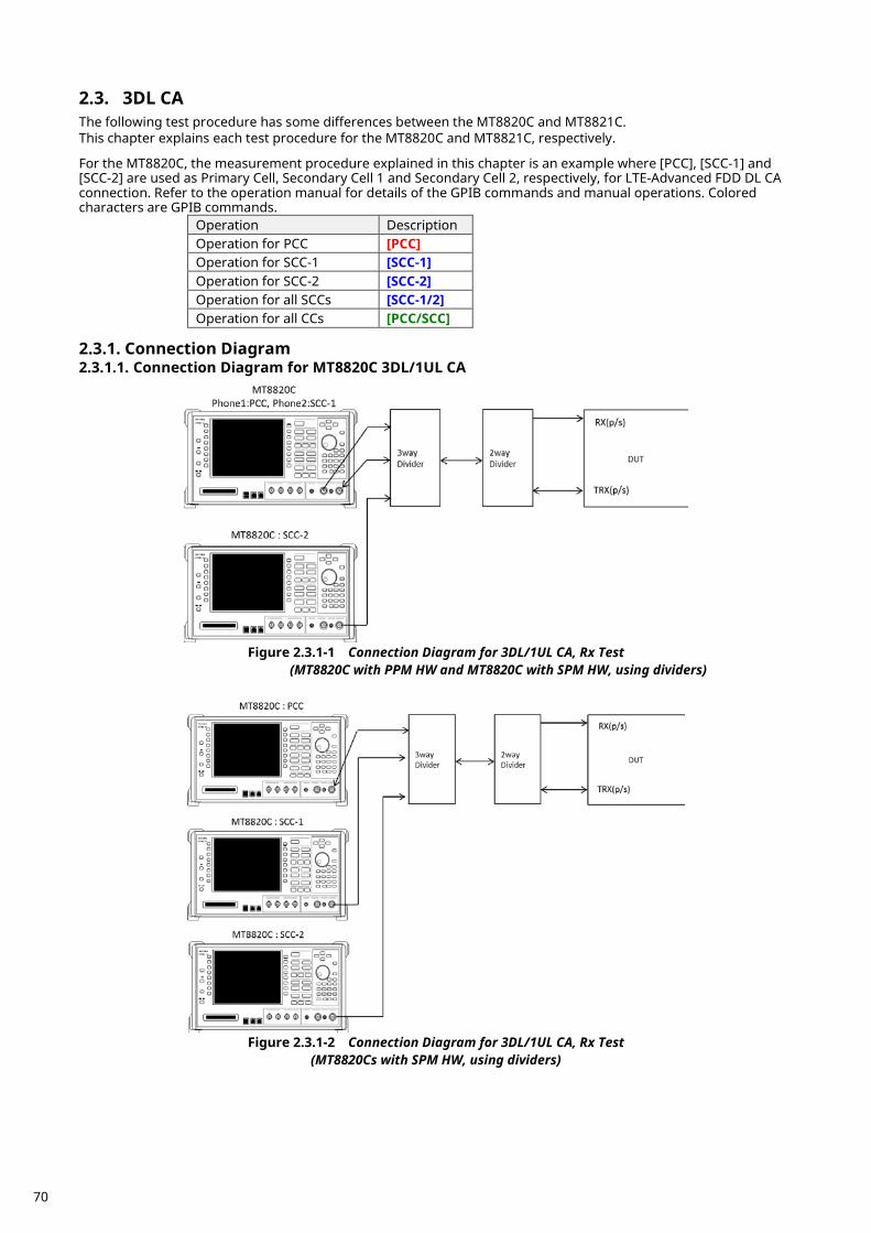
3DL CA 2.3.The following test procedure has some differences between the MT8820C and MT8821C. This chapter explains each test procedure for the MT8820C and MT8821C, respectively. For the MT8820C, the measurement procedure explained in this chapter is an example where [PCC], [SCC-1] and [SCC-2] are used as Primary Cell, Secondary Cell 1 and Secondary Cell 2, respectively, for LTE-Advanced FDD DL CA connection. Refer to the operation manual for details of the GPIB commands and manual operations. Colored characters are GPIB commands.
Operation Description Operation for PCC [PCC] Operation for SCC-1 [SCC-1] Operation for SCC-2 [SCC-2] Operation for all SCCs [SCC-1/2] Operation for all CCs [PCC/SCC]
Connection Diagram 2.3.1.
2.3.1.1. Connection Diagram for MT8820C 3DL/1UL CA
Figure 2.3.1-1 Connection Diagram for 3DL/1UL CA, Rx Test
(MT8820C with PPM HW and MT8820C with SPM HW, using dividers)
Figure 2.3.1-2 Connection Diagram for 3DL/1UL CA, Rx Test
(MT8820Cs with SPM HW, using dividers)
70
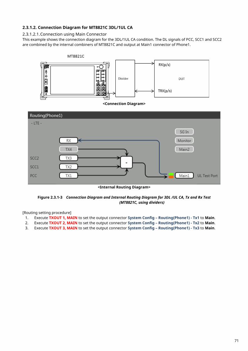
2.3.1.2. Connection Diagram for MT8821C 3DL/1UL CA 2.3.1.2.1. Connection using Main Connector This example shows the connection diagram for the 3DL/1UL CA condition. The DL signals of PCC, SCC1 and SCC2 are combined by the internal combiners of MT8821C and output at Main1 connector of Phone1.
<Connection Diagram>
<Internal Routing Diagram>
Figure 2.3.1-3 Connection Diagram and Internal Routing Diagram for 3DL /UL CA, Tx and Rx Test
(MT8821C, using dividers) [Routing setting procedure]
1. Execute TXOUT 1, MAIN to set the output connector System Config – Routing(Phone1) - Tx1 to Main. 2. Execute TXOUT 2, MAIN to set the output connector System Config – Routing(Phone1) - Tx2 to Main. 3. Execute TXOUT 3, MAIN to set the output connector System Config – Routing(Phone1) - Tx3 to Main.
71
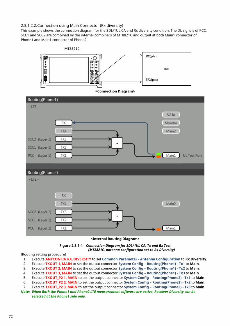
2.3.1.2.2. Connection using Main Connector (Rx diversity) This example shows the connection diagram for the 3DL/1UL CA and Rx diversity condition. The DL signals of PCC, SCC1 and SCC2 are combined by the internal combiners of MT8821C and output at both Main1 connector of Phone1 and Main1 connector of Phone2.
<Connection Diagram>
<Internal Routing Diagram>
Figure 2.3.1-4 Connection Diagram for 3DL/1UL CA, Tx and Rx Test
(MT8821C, antenna configuration set to Rx Diversity) [Routing setting procedure]
1. Execute ANTCONFIG RX_DIVERSITY to set Common Parameter - Antenna Configuration to Rx Diversity. 2. Execute TXOUT 1, MAIN to set the output connector System Config – Routing(Phone1) - Tx1 to Main. 3. Execute TXOUT 2, MAIN to set the output connector System Config – Routing(Phone1) - Tx2 to Main. 4. Execute TXOUT 3, MAIN to set the output connector System Config – Routing(Phone1) - Tx3 to Main. 5. Execute TXOUT_P2 1, MAIN to set the output connector System Config – Routing(Phone2) - Tx1 to Main. 6. Execute TXOUT_P2 2, MAIN to set the output connector System Config – Routing(Phone2) - Tx2 to Main. 7. Execute TXOUT_P2 3, MAIN to set the output connector System Config – Routing(Phone2) - Tx3 to Main.
Note: When Both the Phone1 and Phone2 LTE measurement software are active, Receiver Diversity can be selected at the Phone1 side only.
72
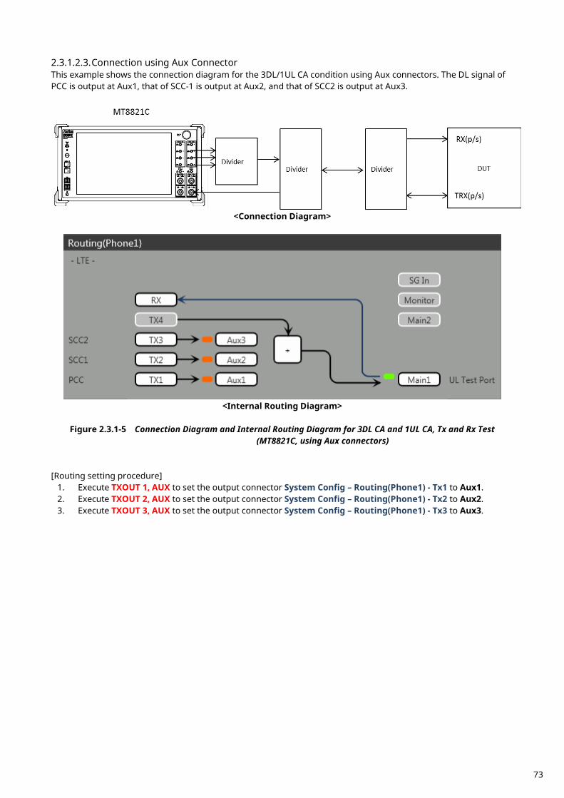
2.3.1.2.3. Connection using Aux Connector This example shows the connection diagram for the 3DL/1UL CA condition using Aux connectors. The DL signal of PCC is output at Aux1, that of SCC-1 is output at Aux2, and that of SCC2 is output at Aux3.
<Connection Diagram>
<Internal Routing Diagram>
Figure 2.3.1-5 Connection Diagram and Internal Routing Diagram for 3DL CA and 1UL CA, Tx and Rx Test
(MT8821C, using Aux connectors) [Routing setting procedure]
1. Execute TXOUT 1, AUX to set the output connector System Config – Routing(Phone1) - Tx1 to Aux1. 2. Execute TXOUT 2, AUX to set the output connector System Config – Routing(Phone1) - Tx2 to Aux2. 3. Execute TXOUT 3, AUX to set the output connector System Config – Routing(Phone1) - Tx3 to Aux3.
73
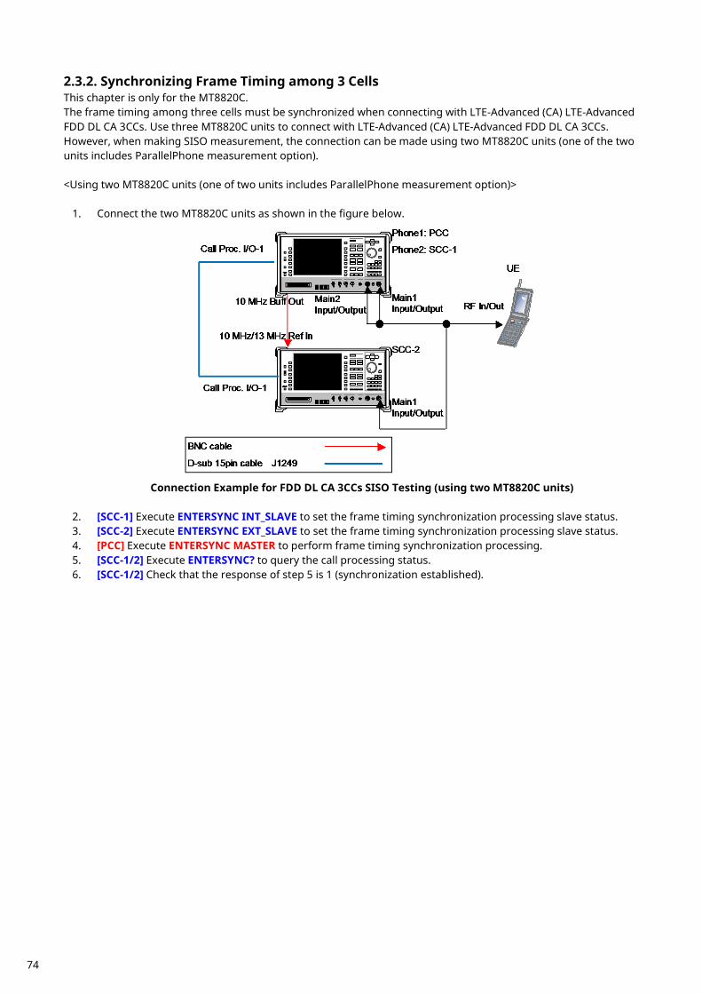
Synchronizing Frame Timing among 3 Cells 2.3.2.This chapter is only for the MT8820C. The frame timing among three cells must be synchronized when connecting with LTE-Advanced (CA) LTE-Advanced FDD DL CA 3CCs. Use three MT8820C units to connect with LTE-Advanced (CA) LTE-Advanced FDD DL CA 3CCs. However, when making SISO measurement, the connection can be made using two MT8820C units (one of the two units includes ParallelPhone measurement option). <Using two MT8820C units (one of two units includes ParallelPhone measurement option)>
1. Connect the two MT8820C units as shown in the figure below.
Connection Example for FDD DL CA 3CCs SISO Testing (using two MT8820C units)
2. [SCC-1] Execute ENTERSYNC INT_SLAVE to set the frame timing synchronization processing slave status. 3. [SCC-2] Execute ENTERSYNC EXT_SLAVE to set the frame timing synchronization processing slave status. 4. [PCC] Execute ENTERSYNC MASTER to perform frame timing synchronization processing. 5. [SCC-1/2] Execute ENTERSYNC? to query the call processing status. 6. [SCC-1/2] Check that the response of step 5 is 1 (synchronization established).
74
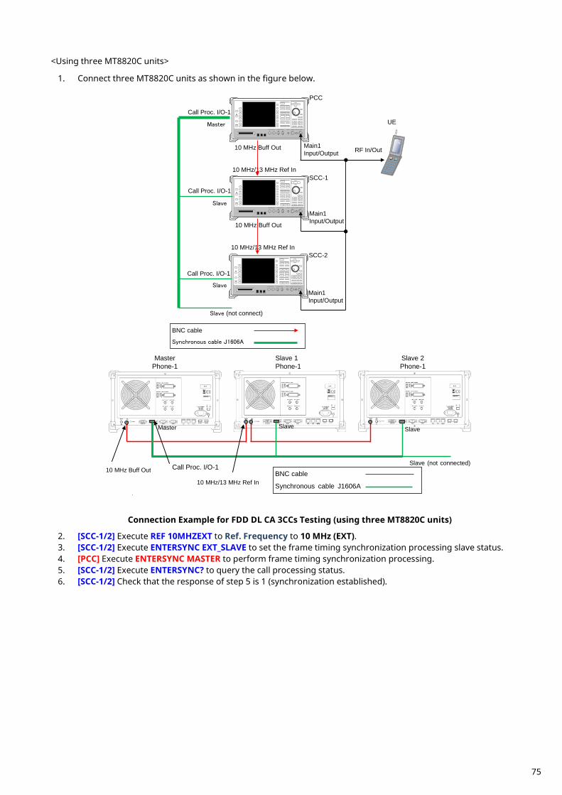
<Using three MT8820C units>
1. Connect three MT8820C units as shown in the figure below.
Main1 Input/Output RF In/Out
UE
Main1 Input/Output
10 MHz/13 MHz Ref In
Call Proc. I/O-1
Call Proc. I/O-1
10 MHz Buff Out
PCC
SCC-1
BNC cable
Synchronous cable J1606A
10 MHz/13 MHz Ref In
10 MHz Buff Out
Main1 Input/Output
Master
Slave
Slave (not connect)
Call Proc. I/O-1
SCC-2
Slave
Call Proc. I/O-1 10 MHz Buff Out
10 MHz/13 MHz Ref In
Master Phone-1
Slave 1 Phone-1
Slave 2 Phone-1
BNC cable
Synchronous cable J1606A
Slave Slave Master
Slave (not connected)
Connection Example for FDD DL CA 3CCs Testing (using three MT8820C units)
2. [SCC-1/2] Execute REF 10MHZEXT to Ref. Frequency to 10 MHz (EXT). 3. [SCC-1/2] Execute ENTERSYNC EXT_SLAVE to set the frame timing synchronization processing slave status. 4. [PCC] Execute ENTERSYNC MASTER to perform frame timing synchronization processing. 5. [SCC-1/2] Execute ENTERSYNC? to query the call processing status. 6. [SCC-1/2] Check that the response of step 5 is 1 (synchronization established).
75
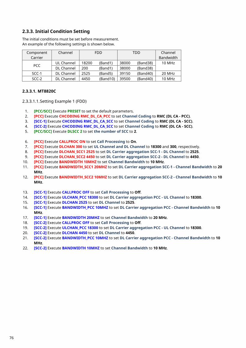
Initial Condition Setting 2.3.3. The initial conditions must be set before measurement. An example of the following settings is shown below.
Component Carrier
Channel FDD TDD Channel Bandwidth
PCC UL Channel 18200 (Band1) 38000 (Band38) 10 MHz DL Channel 200 (Band1) 38000 (Band38)
SCC-1 DL Channel 2525 (Band5) 39150 (Band40) 20 MHz SCC-2 DL Channel 4450 (Band10) 39500 (Band40) 10 MHz
2.3.3.1. MT8820C 2.3.3.1.1. Setting Example 1 (FDD)
1. [PCC/SCC] Execute PRESET to set the default parameters. 2. [PCC] Execute CHCODING RMC_DL_CA_PCC to set Channel Coding to RMC (DL CA - PCC). 3. [SCC-1] Execute CHCODING RMC_DL_CA_SCC to set Channel Coding to RMC (DL CA - SCC). 4. [SCC-2] Execute CHCODING RMC_DL_CA_SCC to set Channel Coding to RMC (DL CA - SCC). 5. [PCC/SCC] Execute DLSCC 2 to set the number of SCC to 2.
6. [PCC] Execute CALLPROC ON to set Call Processing to On. 7. [PCC] Execute DLCHAN 300 to set UL Channel and DL Channel to 18300 and 300, respectively. 8. [PCC] Execute DLCHAN_SCC1 2525 to set DL Carrier aggregation SCC-1 - DL Channel to 2525. 9. [PCC] Execute DLCHAN_SCC2 4450 to set DL Carrier aggregation SCC-2 - DL Channel to 4450.
10. [PCC] Execute BANDWIDTH 10MHZ to set Channel Bandwidth to 10 MHz. 11. [PCC] Execute BANDWIDTH_SCC1 20MHZ to set DL Carrier aggregation SCC-1 - Channel Bandwidth to 20
MHz. 12. [PCC] Execute BANDWIDTH_SCC2 10MHZ to set DL Carrier aggregation SCC-2 - Channel Bandwidth to 10
MHz.
13. [SCC-1] Execute CALLPROC OFF to set Call Processing to Off. 14. [SCC-1] Execute ULCHAN_PCC 18300 to set DL Carrier aggregation PCC - UL Channel to 18300. 15. [SCC-1] Execute DLCHAN 2525 to set DL Channel to 2525. 16. [SCC-1] Execute BANDWIDTH_PCC 10MHZ to set DL Carrier aggregation PCC - Channel Bandwidth to 10
MHz. 17. [SCC-1] Execute BANDWIDTH 20MHZ to set Channel Bandwidth to 20 MHz. 18. [SCC-2] Execute CALLPROC OFF to set Call Processing to Off. 19. [SCC-2] Execute ULCHAN_PCC 18300 to set DL Carrier aggregation PCC - UL Channel to 18300. 20. [SCC-2] Execute DLCHAN 4450 to set DL Channel to 4450. 21. [SCC-2] Execute BANDWIDTH_PCC 10MHZ to set DL Carrier aggregation PCC - Channel Bandwidth to 10
MHz. 22. [SCC-2] Execute BANDWIDTH 10MHZ to set Channel Bandwidth to 10 MHz.
76
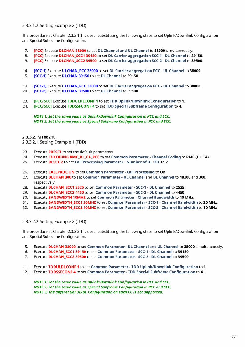
2.3.3.1.2. Setting Example 2 (TDD) The procedure at Chapter 2.3.3.1.1 is used, substituting the following steps to set Uplink/Downlink Configuration and Special Subframe Configuration.
7. [PCC] Execute DLCHAN 38000 to set DL Channel and UL Channel to 38000 simultaneously. 8. [PCC] Execute DLCHAN_SCC1 39150 to set DL Carrier aggregation SCC-1 - DL Channel to 39150. 9. [PCC] Execute DLCHAN_SCC2 39500 to set DL Carrier aggregation SCC-2 - DL Channel to 39500.
14. [SCC-1] Execute ULCHAN_PCC 38000 to set DL Carrier aggregation PCC - UL Channel to 38000. 15. [SCC-1] Execute DLCHAN 39150 to set DL Channel to 39150. 19. [SCC-2] Execute ULCHAN_PCC 38000 to set DL Carrier aggregation PCC - UL Channel to 38000. 20. [SCC-2] Execute DLCHAN 39500 to set DL Channel to 39500. 23. [PCC/SCC] Execute TDDULDLCONF 1 to set TDD Uplink/Downlink Configuration to 1. 24. [PCC/SCC] Execute TDDSSFCONF 4 to set TDD Special Subframe Configuration to 4.
NOTE 1: Set the same value as Uplink/Downlink Configuration in PCC and SCC. NOTE 2: Set the same value as Special Subframe Configuration in PCC and SCC.
2.3.3.2. MT8821C 2.3.3.2.1. Setting Example 1 (FDD) 23. Execute PRESET to set the default parameters. 24. Execute CHCODING RMC_DL_CA_PCC to set Common Parameter - Channel Coding to RMC (DL CA). 25. Execute DLSCC 2 to set Call Processing Parameter - Number of DL SCC to 2.
26. Execute CALLPROC ON to set Common Parameter - Call Processing to On. 27. Execute DLCHAN 300 to set Common Parameter - UL Channel and DL Channel to 18300 and 300,
respectively. 28. Execute DLCHAN_SCC1 2525 to set Common Parameter - SCC-1 - DL Channel to 2525. 29. Execute DLCHAN_SCC2 4450 to set Common Parameter - SCC-2 - DL Channel to 4450. 30. Execute BANDWIDTH 10MHZ to set Common Parameter - Channel Bandwidth to 10 MHz. 31. Execute BANDWIDTH_SCC1 20MHZ to set Common Parameter - SCC-1 - Channel Bandwidth to 20 MHz. 32. Execute BANDWIDTH_SCC2 10MHZ to set Common Parameter - SCC-2 - Channel Bandwidth to 10 MHz. 2.3.3.2.2. Setting Example 2 (TDD) The procedure at Chapter 2.3.3.2.1 is used, substituting the following steps to set Uplink/Downlink Configuration and Special Subframe Configuration.
5. Execute DLCHAN 38000 to set Common Parameter - DL Channel and UL Channel to 38000 simultaneously. 6. Execute DLCHAN_SCC1 39150 to set Common Parameter - SCC-1 - DL Channel to 39150. 7. Execute DLCHAN_SCC2 39500 to set Common Parameter - SCC-2 - DL Channel to 39500.
11. Execute TDDULDLCONF 1 to set Common Parameter - TDD Uplink/Downlink Configuration to 1. 12. Execute TDDSSFCONF 4 to set Common Parameter - TDD Special Subframe Configuration to 4.
NOTE 1: Set the same value as Uplink/Downlink Configuration in PCC and SCC. NOTE 2: Set the same value as Special Subframe Configuration in PCC and SCC. NOTE 3: The differential UL/DL Configuration on each CC is not supported.
77
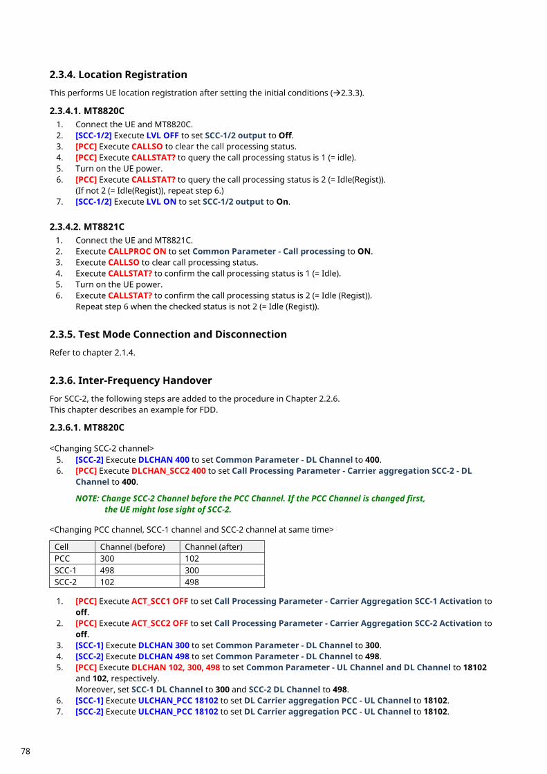
Location Registration 2.3.4. This performs UE location registration after setting the initial conditions (2.3.3). 2.3.4.1. MT8820C
1. Connect the UE and MT8820C. 2. [SCC-1/2] Execute LVL OFF to set SCC-1/2 output to Off. 3. [PCC] Execute CALLSO to clear the call processing status. 4. [PCC] Execute CALLSTAT? to query the call processing status is 1 (= idle). 5. Turn on the UE power. 6. [PCC] Execute CALLSTAT? to query the call processing status is 2 (= Idle(Regist)).
(If not 2 (= Idle(Regist)), repeat step 6.) 7. [SCC-1/2] Execute LVL ON to set SCC-1/2 output to On.
2.3.4.2. MT8821C
1. Connect the UE and MT8821C. 2. Execute CALLPROC ON to set Common Parameter - Call processing to ON. 3. Execute CALLSO to clear call processing status. 4. Execute CALLSTAT? to confirm the call processing status is 1 (= Idle). 5. Turn on the UE power. 6. Execute CALLSTAT? to confirm the call processing status is 2 (= Idle (Regist)).
Repeat step 6 when the checked status is not 2 (= Idle (Regist)).
Test Mode Connection and Disconnection 2.3.5. Refer to chapter 2.1.4.
Inter-Frequency Handover 2.3.6. For SCC-2, the following steps are added to the procedure in Chapter 2.2.6. This chapter describes an example for FDD. 2.3.6.1. MT8820C <Changing SCC-2 channel>
5. [SCC-2] Execute DLCHAN 400 to set Common Parameter - DL Channel to 400. 6. [PCC] Execute DLCHAN_SCC2 400 to set Call Processing Parameter - Carrier aggregation SCC-2 - DL
Channel to 400. NOTE: Change SCC-2 Channel before the PCC Channel. If the PCC Channel is changed first,
the UE might lose sight of SCC-2. <Changing PCC channel, SCC-1 channel and SCC-2 channel at same time>
Cell Channel (before) Channel (after) PCC 300 102 SCC-1 498 300 SCC-2 102 498
1. [PCC] Execute ACT_SCC1 OFF to set Call Processing Parameter - Carrier Aggregation SCC-1 Activation to
off. 2. [PCC] Execute ACT_SCC2 OFF to set Call Processing Parameter - Carrier Aggregation SCC-2 Activation to
off. 3. [SCC-1] Execute DLCHAN 300 to set Common Parameter - DL Channel to 300. 4. [SCC-2] Execute DLCHAN 498 to set Common Parameter - DL Channel to 498. 5. [PCC] Execute DLCHAN 102, 300, 498 to set Common Parameter - UL Channel and DL Channel to 18102
and 102, respectively. Moreover, set SCC-1 DL Channel to 300 and SCC-2 DL Channel to 498.
6. [SCC-1] Execute ULCHAN_PCC 18102 to set DL Carrier aggregation PCC - UL Channel to 18102. 7. [SCC-2] Execute ULCHAN_PCC 18102 to set DL Carrier aggregation PCC - UL Channel to 18102.
78
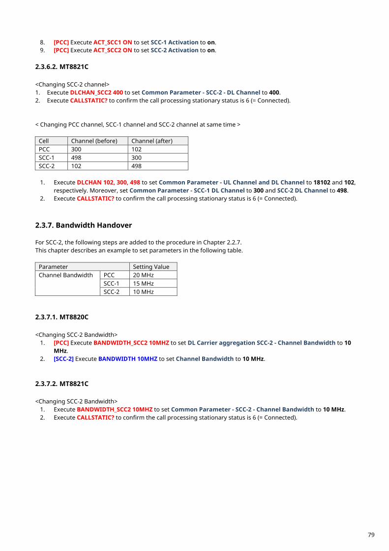
8. [PCC] Execute ACT_SCC1 ON to set SCC-1 Activation to on. 9. [PCC] Execute ACT_SCC2 ON to set SCC-2 Activation to on.
2.3.6.2. MT8821C <Changing SCC-2 channel> 1. Execute DLCHAN_SCC2 400 to set Common Parameter - SCC-2 - DL Channel to 400. 2. Execute CALLSTATIC? to confirm the call processing stationary status is 6 (= Connected). < Changing PCC channel, SCC-1 channel and SCC-2 channel at same time >
Cell Channel (before) Channel (after) PCC 300 102 SCC-1 498 300 SCC-2 102 498
1. Execute DLCHAN 102, 300, 498 to set Common Parameter - UL Channel and DL Channel to 18102 and 102,
respectively. Moreover, set Common Parameter - SCC-1 DL Channel to 300 and SCC-2 DL Channel to 498. 2. Execute CALLSTATIC? to confirm the call processing stationary status is 6 (= Connected).
Bandwidth Handover 2.3.7. For SCC-2, the following steps are added to the procedure in Chapter 2.2.7. This chapter describes an example to set parameters in the following table.
Parameter Setting Value Channel Bandwidth PCC 20 MHz
SCC-1 15 MHz SCC-2 10 MHz
2.3.7.1. MT8820C <Changing SCC-2 Bandwidth>
1. [PCC] Execute BANDWIDTH_SCC2 10MHZ to set DL Carrier aggregation SCC-2 - Channel Bandwidth to 10 MHz.
2. [SCC-2] Execute BANDWIDTH 10MHZ to set Channel Bandwidth to 10 MHz. 2.3.7.2. MT8821C <Changing SCC-2 Bandwidth>
1. Execute BANDWIDTH_SCC2 10MHZ to set Common Parameter - SCC-2 - Channel Bandwidth to 10 MHz. 2. Execute CALLSTATIC? to confirm the call processing stationary status is 6 (= Connected).
79
Changing DL/UL RB Allocation and MCS Index of Each CCs 2.3.8.The change procedure for DL/UL RB allocation and MCS Index for PCC and SCC is same as 2CA (refer to Chapter 2.2.8). This chapter focuses on SCC-2 and describes how to change the SCC-2 DL RB allocation and MCS Index. 2.3.8.1. MT8820C 1. Changing SCC-2 DL RB Allocation and MCS Indexes For SCC-2, the following steps are added to the procedure in Chapter 2.2.8. This chapter describes an example where the Channel Bandwidth is 10 MHz. 1. [PCC] Execute DLIMCS1_SCC2 11 to set DL Carrier aggregation SCC-2 - DL RMC - MCS Index 1 to 11. 2. [PCC] Execute DLIMCS2_SCC2 12 to set DL Carrier aggregation SCC-2 - DL RMC - MCS Index 2 to 12. 3. [PCC] Execute DLIMCS3_SCC2 13 to set DL Carrier aggregation SCC-2 - DL RMC - MCS Index 3 to 13.
4. [SCC-2] Execute DLRMC_RB 25 to set DL RMC - Number of RB to 25. 5. [SCC-2] Execute DLIMCS1 11 to set DL RMC - MCS Index 1 to 11. 6. [SCC-2] Execute DLIMCS2 12 to set DL RMC - MCS Index 2 to 12. 7. [SCC-2] Execute DLIMCS3 13 to set DL RMC - MCS Index 3 to 13. <When TDD CA> 8. [PCC] Execute DLIMCS1_SCC4 8 to set DL Carrier aggregation SCC-2 - DL RMC - MCS Index 4 to 8. 9. [SCC-1] Execute DLIMCS4 8 to set DL RMC - MCS Index 4 to 8. 2.3.8.2. MT8821C 1. Changing SCC-2 DL RB Allocation and MCS Indexes For SCC-2, the following steps are added to the procedure in Chapter 2.2.8 This chapter describes an example where the Channel Bandwidth is 10 MHz.
1. Execute DLIMCS1_SCC2 11 to set Common Parameter - SCC-2 - DL RMC - MCS Index 1 to 11. 2. Execute DLIMCS2_SCC2 12 to set Common Parameter - SCC-2 - DL RMC - MCS Index 2 to 12. 3. Execute DLIMCS3_SCC2 13 to set Common Parameter - SCC-2 - DL RMC - MCS Index 3 to 13.
<When TDD CA> 4. Execute DLIMCS4_SCC2 8 to set Common Parameter - SCC-2 - DL RMC - MCS Index 4 to 8.
80
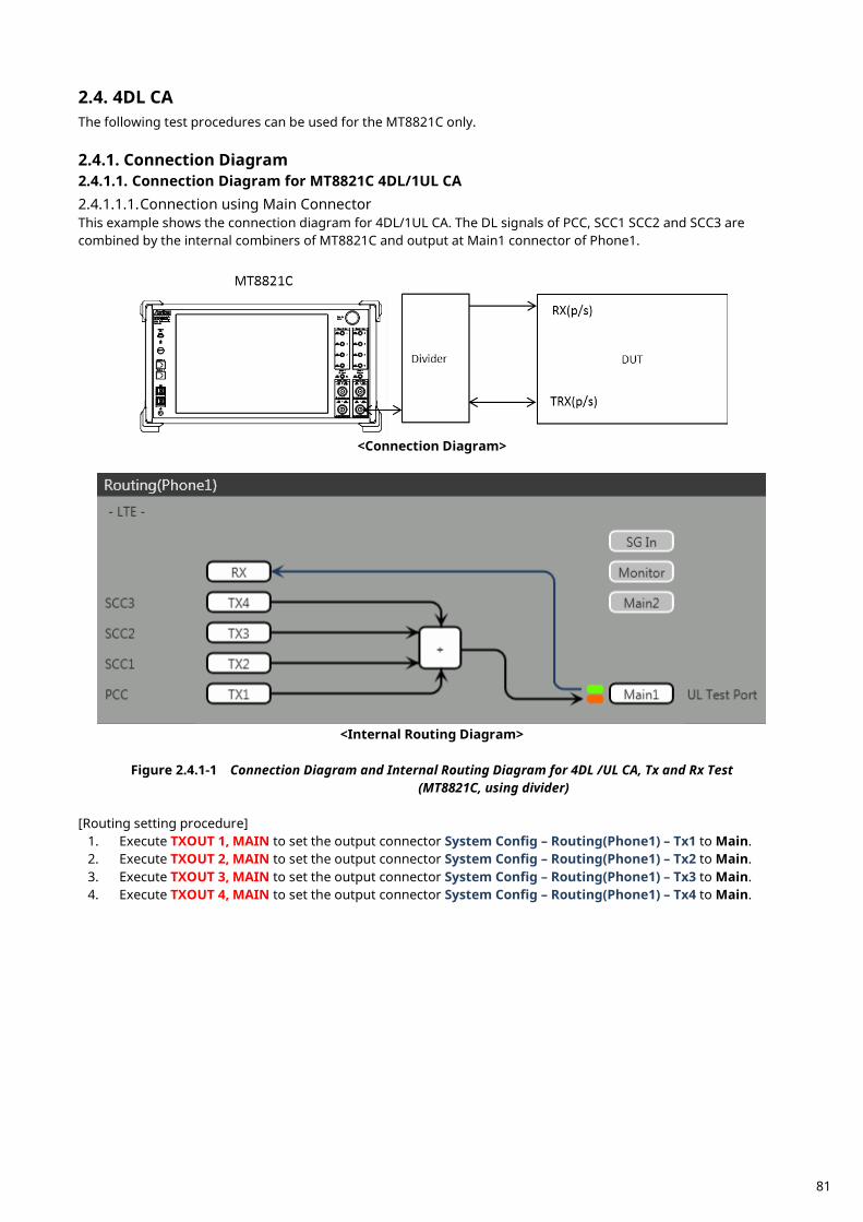
4DL CA 2.4.The following test procedures can be used for the MT8821C only.
Connection Diagram 2.4.1.2.4.1.1. Connection Diagram for MT8821C 4DL/1UL CA 2.4.1.1.1. Connection using Main Connector This example shows the connection diagram for 4DL/1UL CA. The DL signals of PCC, SCC1 SCC2 and SCC3 are combined by the internal combiners of MT8821C and output at Main1 connector of Phone1.
<Connection Diagram>
<Internal Routing Diagram>
Figure 2.4.1-1 Connection Diagram and Internal Routing Diagram for 4DL /UL CA, Tx and Rx Test
(MT8821C, using divider) [Routing setting procedure]
1. Execute TXOUT 1, MAIN to set the output connector System Config – Routing(Phone1) – Tx1 to Main. 2. Execute TXOUT 2, MAIN to set the output connector System Config – Routing(Phone1) – Tx2 to Main. 3. Execute TXOUT 3, MAIN to set the output connector System Config – Routing(Phone1) – Tx3 to Main. 4. Execute TXOUT 4, MAIN to set the output connector System Config – Routing(Phone1) – Tx4 to Main.
81
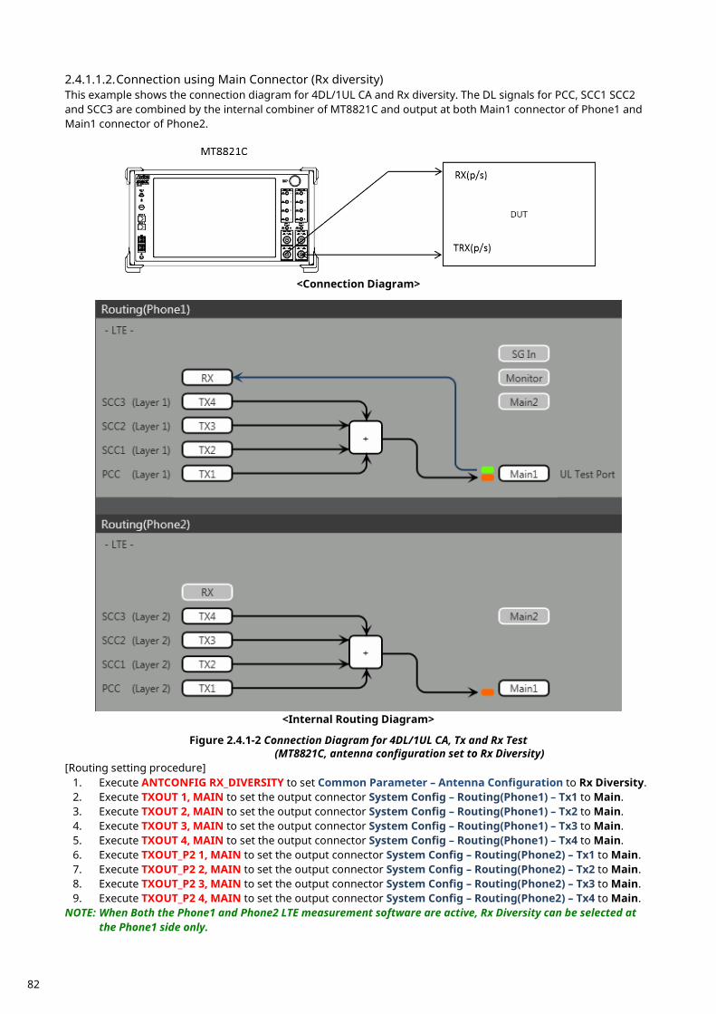
2.4.1.1.2. Connection using Main Connector (Rx diversity) This example shows the connection diagram for 4DL/1UL CA and Rx diversity. The DL signals for PCC, SCC1 SCC2 and SCC3 are combined by the internal combiner of MT8821C and output at both Main1 connector of Phone1 and Main1 connector of Phone2.
<Connection Diagram>
<Internal Routing Diagram>
Figure 2.4.1-2 Connection Diagram for 4DL/1UL CA, Tx and Rx Test
(MT8821C, antenna configuration set to Rx Diversity) [Routing setting procedure]
1. Execute ANTCONFIG RX_DIVERSITY to set Common Parameter – Antenna Configuration to Rx Diversity. 2. Execute TXOUT 1, MAIN to set the output connector System Config – Routing(Phone1) – Tx1 to Main. 3. Execute TXOUT 2, MAIN to set the output connector System Config – Routing(Phone1) – Tx2 to Main. 4. Execute TXOUT 3, MAIN to set the output connector System Config – Routing(Phone1) – Tx3 to Main. 5. Execute TXOUT 4, MAIN to set the output connector System Config – Routing(Phone1) – Tx4 to Main. 6. Execute TXOUT_P2 1, MAIN to set the output connector System Config – Routing(Phone2) – Tx1 to Main. 7. Execute TXOUT_P2 2, MAIN to set the output connector System Config – Routing(Phone2) – Tx2 to Main. 8. Execute TXOUT_P2 3, MAIN to set the output connector System Config – Routing(Phone2) – Tx3 to Main. 9. Execute TXOUT_P2 4, MAIN to set the output connector System Config – Routing(Phone2) – Tx4 to Main.
NOTE: When Both the Phone1 and Phone2 LTE measurement software are active, Rx Diversity can be selected at the Phone1 side only.
82
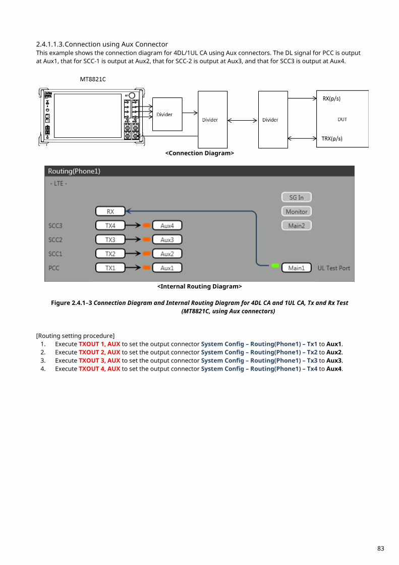
2.4.1.1.3. Connection using Aux Connector This example shows the connection diagram for 4DL/1UL CA using Aux connectors. The DL signal for PCC is output at Aux1, that for SCC-1 is output at Aux2, that for SCC-2 is output at Aux3, and that for SCC3 is output at Aux4.
<Connection Diagram>
<Internal Routing Diagram>
Figure 2.4.1–3 Connection Diagram and Internal Routing Diagram for 4DL CA and 1UL CA, Tx and Rx Test
(MT8821C, using Aux connectors) [Routing setting procedure]
1. Execute TXOUT 1, AUX to set the output connector System Config – Routing(Phone1) – Tx1 to Aux1. 2. Execute TXOUT 2, AUX to set the output connector System Config – Routing(Phone1) – Tx2 to Aux2. 3. Execute TXOUT 3, AUX to set the output connector System Config – Routing(Phone1) – Tx3 to Aux3. 4. Execute TXOUT 4, AUX to set the output connector System Config – Routing(Phone1) – Tx4 to Aux4.
83

Initial Condition Setting 2.4.2. The initial conditions must be set before measurement. An example of the following settings is shown below.
Component Carrier
Channel FDD TDD Channel Bandwidth
PCC UL Channel 18300 (Band1) 38000 (Band38) 10 MHz DL Channel 300 (Band1) 38000 (Band38)
SCC–1 DL Channel 2525 (Band5) 39150 (Band40) 20 MHz SCC–2 DL Channel 4450 (Band10) 39500 (Band40) 10 MHz SCC–2 DL Channel 444 (Band10) 38144 (Band40) 20 MHz
2.4.2.1. MT8821C 2.4.2.1.1. Setting Example 1 (FDD)
1. Execute PRESET to set the default parameters. 2. Execute CHCODING RMC_DL_CA_PCC to set Common Parameter – Channel Coding to RMC (DL CA). 3. Execute DLSCC 3 to set Call Processing Parameter – Number of DL SCC to 3.
4. Execute CALLPROC ON to set Common Parameter – Call Processing to On. 5. Execute DLCHAN 300 to set Common Parameter – UL Channel and DL Channel to 18300 and 300,
respectively. 6. Execute DLCHAN_SCC1 2525 to set Common Parameter – SCC-1 – DL Channel to 2525. 7. Execute DLCHAN_SCC2 4450 to set Common Parameter – SCC-2 – DL Channel to 4450. 8. Execute DLCHAN_SCC3 444 to set Common Parameter – SCC-3 – DL Channel to 444. 9. Execute BANDWIDTH 10MHZ to set Common Parameter - Channel Bandwidth to 10 MHz.
10. Execute BANDWIDTH_SCC1 20MHZ to set Common Parameter – SCC-1 – Channel Bandwidth to 20 MHz. 11. Execute BANDWIDTH_SCC2 10MHZ to set Common Parameter – SCC-2 – Channel Bandwidth to 10 MHz. 12. Execute BANDWIDTH_SCC3 20MHZ to set Common Parameter – SCC-3 – Channel Bandwidth to 20 MHz. 2.4.2.1.2. Setting Example 2 (TDD) The procedure described in Chapter 2.3.3.2.1 is used, but substituting the following steps to set Uplink/Downlink Configuration and Special Subframe Configuration.
5. Execute DLCHAN 38000 to set Common Parameter – DL Channel and UL Channel to 38000 simultaneously.
6. Execute DLCHAN_SCC1 39150 to set Common Parameter – SCC-1 – DL Channel to 39150. 7. Execute DLCHAN_SCC2 39500 to set Common Parameter – SCC-2 – DL Channel to 39500. 8. Execute DLCHAN_SCC3 38144 to set Common Parameter – SCC-3 – DL Channel to 38144.
13. Execute TDDULDLCONF 1 to set Common Parameter – TDD Uplink/Downlink Configuration to 1. 14. Execute TDDSSFCONF 4 to set Common Parameter – TDD Special Subframe Configuration to 4.
NOTE 1: Set the same value as Uplink/Downlink Configuration in PCC and SCC. NOTE 2: Set the same value as Special Subframe Configuration in PCC and SCC. NOTE 3: The differential UL/DL Configuration on each CC is not supported.
84
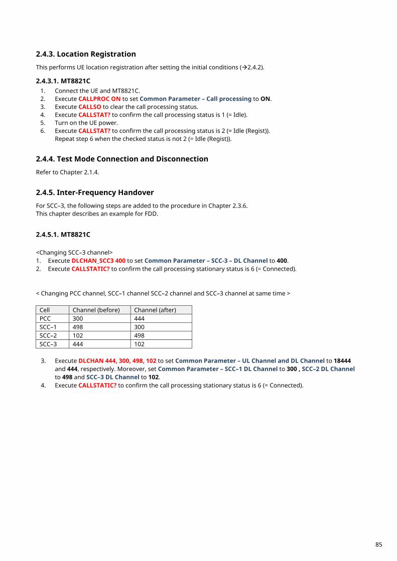
Location Registration 2.4.3. This performs UE location registration after setting the initial conditions (2.4.2). 2.4.3.1. MT8821C
1. Connect the UE and MT8821C. 2. Execute CALLPROC ON to set Common Parameter – Call processing to ON. 3. Execute CALLSO to clear the call processing status. 4. Execute CALLSTAT? to confirm the call processing status is 1 (= Idle). 5. Turn on the UE power. 6. Execute CALLSTAT? to confirm the call processing status is 2 (= Idle (Regist)).
Repeat step 6 when the checked status is not 2 (= Idle (Regist)).
Test Mode Connection and Disconnection 2.4.4. Refer to Chapter 2.1.4.
Inter-Frequency Handover 2.4.5. For SCC–3, the following steps are added to the procedure in Chapter 2.3.6. This chapter describes an example for FDD. 2.4.5.1. MT8821C <Changing SCC–3 channel> 1. Execute DLCHAN_SCC3 400 to set Common Parameter – SCC-3 – DL Channel to 400. 2. Execute CALLSTATIC? to confirm the call processing stationary status is 6 (= Connected). < Changing PCC channel, SCC–1 channel SCC–2 channel and SCC–3 channel at same time >
Cell Channel (before) Channel (after) PCC 300 444 SCC–1 498 300 SCC–2 102 498 SCC–3 444 102
3. Execute DLCHAN 444, 300, 498, 102 to set Common Parameter – UL Channel and DL Channel to 18444
and 444, respectively. Moreover, set Common Parameter – SCC–1 DL Channel to 300 , SCC–2 DL Channel to 498 and SCC–3 DL Channel to 102.
4. Execute CALLSTATIC? to confirm the call processing stationary status is 6 (= Connected).
85
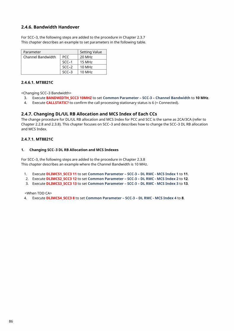
Bandwidth Handover 2.4.6. For SCC–3, the following steps are added to the procedure in Chapter 2.3.7 This chapter describes an example to set parameters in the following table.
Parameter Setting Value Channel Bandwidth PCC 20 MHz
SCC–1 15 MHz SCC–2 10 MHz SCC–3 10 MHz
2.4.6.1. MT8821C <Changing SCC–3 Bandwidth>
3. Execute BANDWIDTH_SCC3 10MHZ to set Common Parameter – SCC-3 – Channel Bandwidth to 10 MHz. 4. Execute CALLSTATIC? to confirm the call processing stationary status is 6 (= Connected).
Changing DL/UL RB Allocation and MCS Index of Each CCs 2.4.7.The change procedure for DL/UL RB allocation and MCS Index for PCC and SCC is the same as 2CA/3CA (refer to Chapter 2.2.8 and 2.3.8). This chapter focuses on SCC–3 and describes how to change the SCC–3 DL RB allocation and MCS Index. 2.4.7.1. MT8821C 1. Changing SCC–3 DL RB Allocation and MCS Indexes For SCC–3, the following steps are added to the procedure in Chapter 2.3.8 This chapter describes an example where the Channel Bandwidth is 10 MHz.
1. Execute DLIMCS1_SCC3 11 to set Common Parameter – SCC-3 – DL RMC - MCS Index 1 to 11. 2. Execute DLIMCS2_SCC3 12 to set Common Parameter – SCC-3 – DL RMC - MCS Index 2 to 12. 3. Execute DLIMCS3_SCC3 13 to set Common Parameter – SCC-3 – DL RMC - MCS Index 3 to 13.
<When TDD CA> 4. Execute DLIMCS4_SCC3 8 to set Common Parameter – SCC-3 – DL RMC - MCS Index 4 to 8.
86
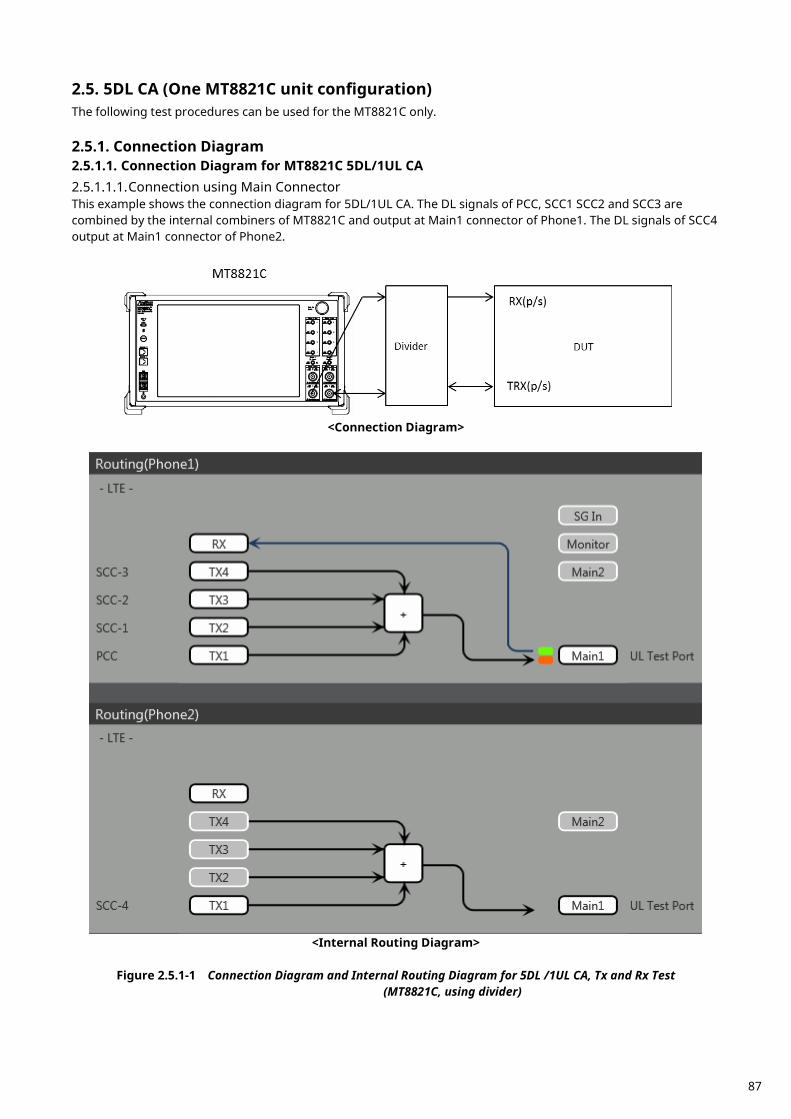
5DL CA (One MT8821C unit configuration) 2.5.The following test procedures can be used for the MT8821C only.
Connection Diagram 2.5.1.2.5.1.1. Connection Diagram for MT8821C 5DL/1UL CA 2.5.1.1.1. Connection using Main Connector This example shows the connection diagram for 5DL/1UL CA. The DL signals of PCC, SCC1 SCC2 and SCC3 are combined by the internal combiners of MT8821C and output at Main1 connector of Phone1. The DL signals of SCC4 output at Main1 connector of Phone2.
<Connection Diagram>
<Internal Routing Diagram>
Figure 2.5.1-1 Connection Diagram and Internal Routing Diagram for 5DL /1UL CA, Tx and Rx Test
(MT8821C, using divider)
87
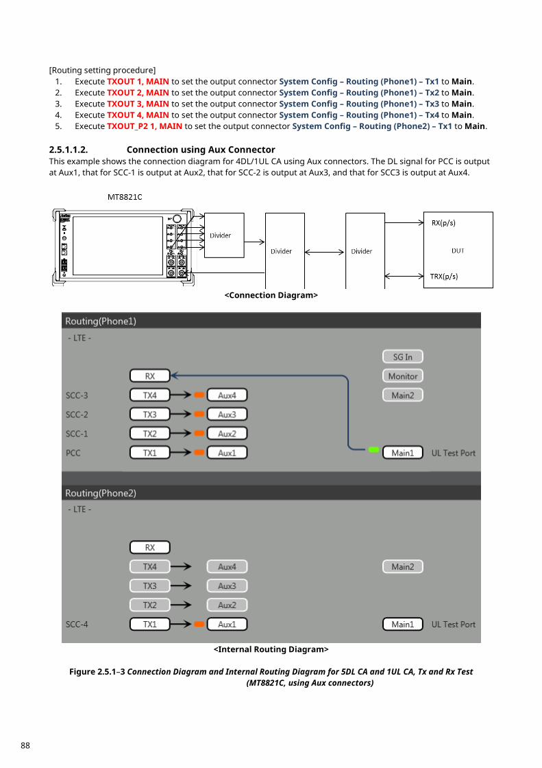
[Routing setting procedure]
1. Execute TXOUT 1, MAIN to set the output connector System Config – Routing (Phone1) – Tx1 to Main. 2. Execute TXOUT 2, MAIN to set the output connector System Config – Routing (Phone1) – Tx2 to Main. 3. Execute TXOUT 3, MAIN to set the output connector System Config – Routing (Phone1) – Tx3 to Main. 4. Execute TXOUT 4, MAIN to set the output connector System Config – Routing (Phone1) – Tx4 to Main. 5. Execute TXOUT_P2 1, MAIN to set the output connector System Config – Routing (Phone2) – Tx1 to Main.
2.5.1.1.2. Connection using Aux Connector This example shows the connection diagram for 4DL/1UL CA using Aux connectors. The DL signal for PCC is output at Aux1, that for SCC-1 is output at Aux2, that for SCC-2 is output at Aux3, and that for SCC3 is output at Aux4.
<Connection Diagram>
<Internal Routing Diagram>
Figure 2.5.1–3 Connection Diagram and Internal Routing Diagram for 5DL CA and 1UL CA, Tx and Rx Test
(MT8821C, using Aux connectors)
88

[Routing setting procedure] 1. Execute TXOUT 1, AUX to set the output connector System Config – Routing(Phone1) – Tx1 to Aux1. 2. Execute TXOUT 2, AUX to set the output connector System Config – Routing(Phone1) – Tx2 to Aux2. 3. Execute TXOUT 3, AUX to set the output connector System Config – Routing(Phone1) – Tx3 to Aux3. 4. Execute TXOUT 4, AUX to set the output connector System Config – Routing(Phone1) – Tx4 to Aux4. 5. Execute TXOUT_P2 1, AUX to set the output connector System Config – Routing(Phone2) – Tx1 to Aux1.
Initial Condition Setting 2.5.2. The initial conditions must be set before measurement. An example of the following settings is shown below.
Component Carrier
Channel FDD TDD Channel Bandwidth
PCC UL Channel 18300 (Band1) 38000 (Band38) 10 MHz DL Channel 300 (Band1) 38000 (Band38)
SCC–1 DL Channel 2525 (Band5) 39150 (Band40) 20 MHz SCC–2 DL Channel 4450 (Band10) 39500 (Band40) 10 MHz SCC–3 DL Channel 444 (Band1) 38144 (Band40) 20 MHz SCC–4 DL Channel 1575 (Band3) 38450 (Band39) 10 MHz
2.5.2.1. MT8821C 2.5.2.1.1. Setting Example 1 (FDD)
1. Execute PRESET to set the default parameters. 2. Execute CHCODING RMC_DL_CA_PCC to set Common Parameter – Channel Coding to RMC (DL CA). 3. Execute DLSCC 4 to set Call Processing Parameter – Number of DL SCC to 4.
4. Execute CALLPROC ON to set Common Parameter – Call Processing to On. 5. Execute DUP_CC_SRC SCC2 to set Common Parameter – SCC4- Duplicate CC Source to SCC2. 6. Execute DLCHAN 300 to set Common Parameter – UL Channel and DL Channel to 18300 and 300,
respectively. 7. Execute DLCHAN_SCC1 2525 to set Common Parameter – SCC-1 – DL Channel to 2525. 8. Execute DLCHAN_SCC2 4450 to set Common Parameter – SCC-2 – DL Channel to 4450. 9. Execute DLCHAN_SCC3 444 to set Common Parameter – SCC-3 – DL Channel to 444.
10. Execute DLCHAN_SCC4 1575 to set Common Parameter – SCC-4 – DL Channel to 1575. 11. Execute BANDWIDTH 10MHZ to set Common Parameter - Channel Bandwidth to 10 MHz. 12. Execute BANDWIDTH_SCC1 20MHZ to set Common Parameter – SCC-1 – Channel Bandwidth to 20 MHz. 13. Execute BANDWIDTH_SCC2 10MHZ to set Common Parameter – SCC-2 – Channel Bandwidth to 10 MHz. 14. Execute BANDWIDTH_SCC3 20MHZ to set Common Parameter – SCC-3 – Channel Bandwidth to 20 MHz. 2.5.2.1.2. Setting Example 2 (TDD) The procedure described in Chapter 2.3.3.2.1 is used, but substituting the following steps to set Uplink/Downlink Configuration and Special Subframe Configuration.
6. Execute DLCHAN 38000 to set Common Parameter – DL Channel and UL Channel to 38000 simultaneously.
7. Execute DLCHAN_SCC1 39150 to set Common Parameter – SCC-1 – DL Channel to 39150. 8. Execute DLCHAN_SCC2 39500 to set Common Parameter – SCC-2 – DL Channel to 39500. 9. Execute DLCHAN_SCC3 38144 to set Common Parameter – SCC-3 – DL Channel to 38144.
10. Execute DLCHAN_SCC4 38450 to set Common Parameter – SCC-4 – DL Channel to 38450. 15. Execute TDDULDLCONF 1 to set Common Parameter – TDD Uplink/Downlink Configuration to 1. 16. Execute TDDSSFCONF 4 to set Common Parameter – TDD Special Subframe Configuration to 4.
NOTE 1: Set the same value as Uplink/Downlink Configuration in PCC and SCC. NOTE 2: Set the same value as Special Subframe Configuration in PCC and SCC. NOTE 3: The differential UL/DL Configuration on each CC is not supported.
89
Location Registration 2.5.3. This performs UE location registration after setting the initial conditions (2.5.2). 2.5.3.1. MT8821C
1. Connect the UE and MT8821C. 2. Execute CALLPROC ON to set Common Parameter – Call processing to ON. 3. Execute CALLSO to clear the call processing status. 4. Execute CALLSTAT? to confirm the call processing status is 1 (= Idle). 5. Turn on the UE power. 6. Execute CALLSTAT? to confirm the call processing status is 2 (= Idle (Regist)).
Repeat step 6 when the checked status is not 2 (= Idle (Regist)).
Test Mode Connection and Disconnection 2.5.4. Refer to Chapter 2.1.4.
Inter-Frequency Handover 2.5.5. For SCC–4, the following steps are added to the procedure in Chapter2.4.5 This chapter describes an example for FDD. 2.5.5.1. MT8821C <Changing SCC–4 channel> 1. Execute DLCHAN_SCC4 1550 to set Common Parameter – SCC-4 – DL Channel to 1550. 2. Execute CALLSTATIC? to confirm the call processing stationary status is 6 (= Connected).
90
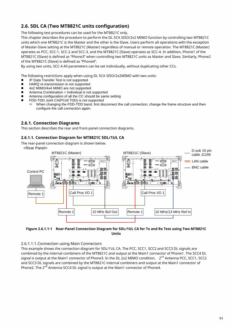
5DL CA (Two MT8821C units configuration) 2.6.The following test procedures can be used for the MT8821C only. This chapter describes the procedure to perform the DL 5CA SISO/2x2 MIMO function by controlling two MT8821C units which one MT8821C is the Master and the other is the Slave. Users perform all operations with the exception of Master-Slave setting at the MT8821C (Master) regardless of manual or remote operation. The MT8821C (Master) operates as PCC, SCC-1, SCC-2 and SCC-3, and the MT8821C (Slave) operates as SCC-4. In addition, Phone1 of the MT8821C (Slave) is defined as “Phone3” when controlling two MT8821C units as Master and Slave. Similarly, Phone2 of the MT8821C (Slave) is defined as “Phone4”. By using two units, SCC-4 All parameters can be set individually, without duplicating other CCs. The following restrictions apply when using DL 5CA SISO/2x2MIMO with two units: IP Data Transfer Test is not supported HARQ re-transmission is not supported 4x2 MIMO/4x4 MIMO are not supported Antenna Combination = Individual is not supported Antenna configuration of all the CC should be same setting FDD-TDD Joint CA(PCell TDD) is not supported
When changing the FDD-TDD band, first disconnect the call connection, change the frame structure and then configure the call connection again.
Connection Diagrams 2.6.1.This section describes the rear and front-panel connection diagrams. 2.6.1.1. Connection Diagram for MT8821C 5DL/1UL CA The rear-panel connection diagram is shown below.
Figure 2.6.1.1-1 Rear-Panel Connection Diagram for 5DL/1UL CA for Tx and Rx Test using Two MT8821C
Units 2.6.1.1.1. Connection using Main Connectors This example shows the connection diagram for 5DL/1UL CA. The PCC, SCC1, SCC2 and SCC3 DL signals are combined by the internal combiners of the MT8821C and output at the Main1 connector of Phone1. The SCC4 DL signal is output at the Main1 connector of Phone3. In the DL 2x2 MIMO condition, 2nd Antenna PCC, SCC1, SCC2 and SCC3 DL signals are combined by the MT8821C internal combiners and output at the Main1 connector of Phone2. The 2nd Antenna SCC4 DL signal is output at the Main1 connector of Phone4.
MT8821C (Master) MT8821C (Slave)
Control PC
Remote 1 Call Proc I/O 1 Call Proc I/O 1
Remote 2 Remote 1 10 MHz Buf Out 10 MHz/13 MHz Ref In
<Rear Panel> D-sub 15 pin cable J1249
LAN cable
BNC cable
91
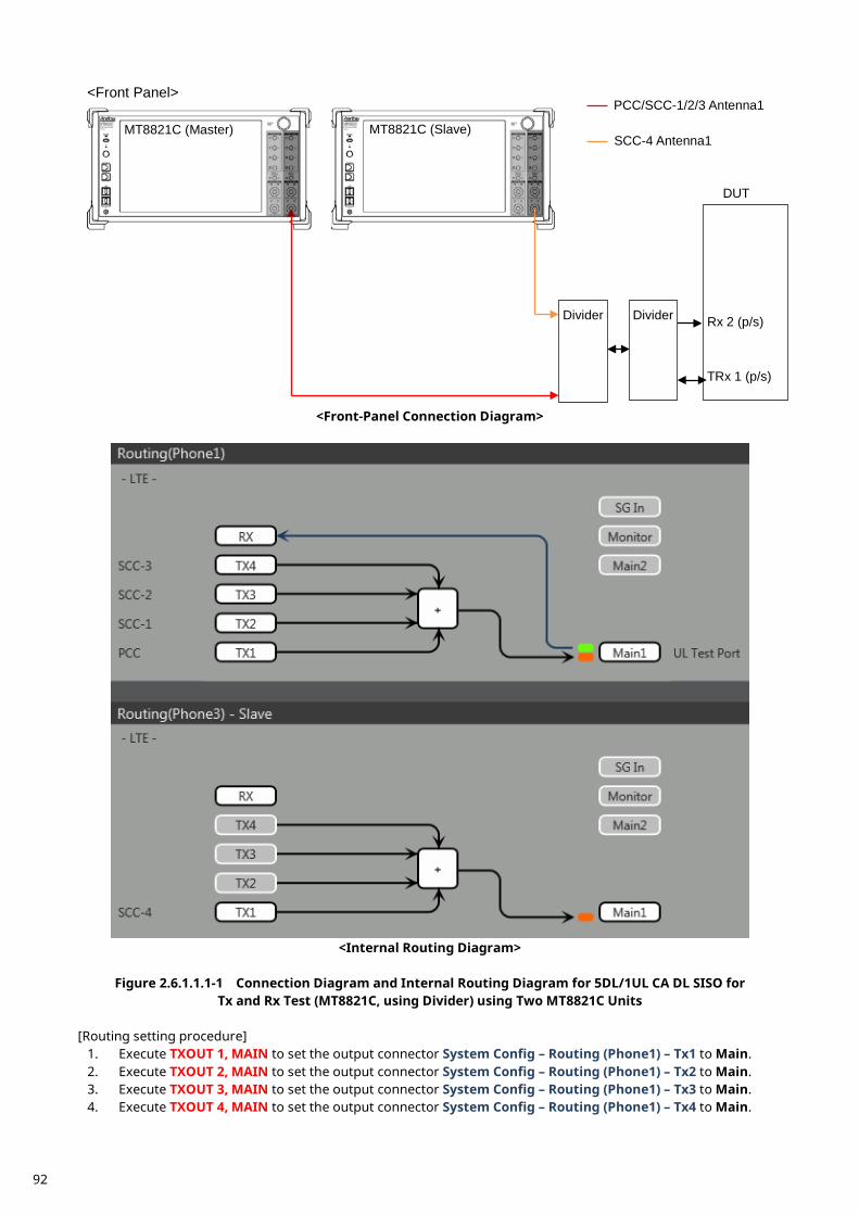
<Front-Panel Connection Diagram>
<Internal Routing Diagram>
Figure 2.6.1.1.1-1 Connection Diagram and Internal Routing Diagram for 5DL/1UL CA DL SISO for
Tx and Rx Test (MT8821C, using Divider) using Two MT8821C Units [Routing setting procedure]
1. Execute TXOUT 1, MAIN to set the output connector System Config – Routing (Phone1) – Tx1 to Main. 2. Execute TXOUT 2, MAIN to set the output connector System Config – Routing (Phone1) – Tx2 to Main. 3. Execute TXOUT 3, MAIN to set the output connector System Config – Routing (Phone1) – Tx3 to Main. 4. Execute TXOUT 4, MAIN to set the output connector System Config – Routing (Phone1) – Tx4 to Main.
Rx 2 (p/s)
TRx 1 (p/s)
DUT
Divider
MT8821C (Master) MT8821C (Slave)
<Front Panel>
SCC-4 Antenna1
PCC/SCC-1/2/3 Antenna1
Divider
92
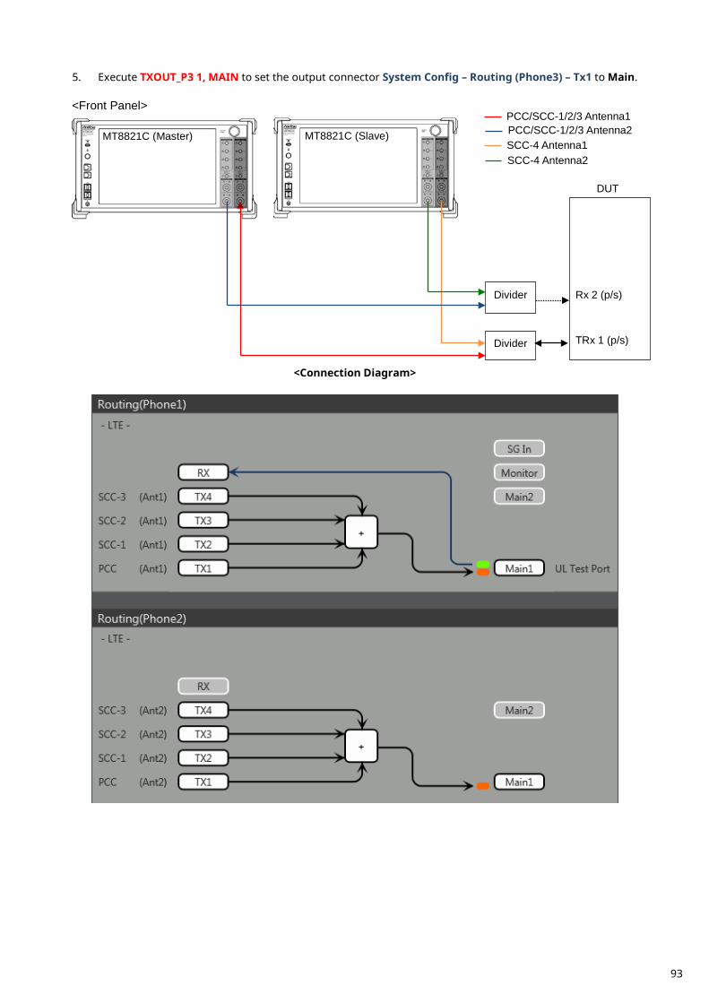
5. Execute TXOUT_P3 1, MAIN to set the output connector System Config – Routing (Phone3) – Tx1 to Main.
<Connection Diagram>
Rx 2 (p/s)
TRx 1 (p/s)
DUT
Divider
Divider
MT8821C (Master) MT8821C (Slave)
<Front Panel>
SCC-4 Antenna1 PCC/SCC-1/2/3 Antenna2 PCC/SCC-1/2/3 Antenna1
SCC-4 Antenna2
93
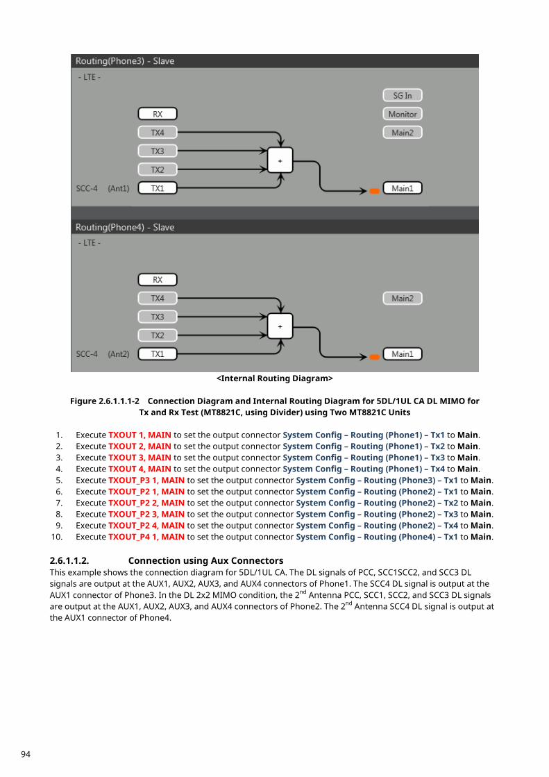
<Internal Routing Diagram>
Figure 2.6.1.1.1-2 Connection Diagram and Internal Routing Diagram for 5DL/1UL CA DL MIMO for
Tx and Rx Test (MT8821C, using Divider) using Two MT8821C Units
1. Execute TXOUT 1, MAIN to set the output connector System Config – Routing (Phone1) – Tx1 to Main. 2. Execute TXOUT 2, MAIN to set the output connector System Config – Routing (Phone1) – Tx2 to Main. 3. Execute TXOUT 3, MAIN to set the output connector System Config – Routing (Phone1) – Tx3 to Main. 4. Execute TXOUT 4, MAIN to set the output connector System Config – Routing (Phone1) – Tx4 to Main. 5. Execute TXOUT_P3 1, MAIN to set the output connector System Config – Routing (Phone3) – Tx1 to Main. 6. Execute TXOUT_P2 1, MAIN to set the output connector System Config – Routing (Phone2) – Tx1 to Main. 7. Execute TXOUT_P2 2, MAIN to set the output connector System Config – Routing (Phone2) – Tx2 to Main. 8. Execute TXOUT_P2 3, MAIN to set the output connector System Config – Routing (Phone2) – Tx3 to Main. 9. Execute TXOUT_P2 4, MAIN to set the output connector System Config – Routing (Phone2) – Tx4 to Main.
10. Execute TXOUT_P4 1, MAIN to set the output connector System Config – Routing (Phone4) – Tx1 to Main. 2.6.1.1.2. Connection using Aux Connectors This example shows the connection diagram for 5DL/1UL CA. The DL signals of PCC, SCC1SCC2, and SCC3 DL signals are output at the AUX1, AUX2, AUX3, and AUX4 connectors of Phone1. The SCC4 DL signal is output at the AUX1 connector of Phone3. In the DL 2x2 MIMO condition, the 2nd Antenna PCC, SCC1, SCC2, and SCC3 DL signals are output at the AUX1, AUX2, AUX3, and AUX4 connectors of Phone2. The 2nd Antenna SCC4 DL signal is output at the AUX1 connector of Phone4.
94
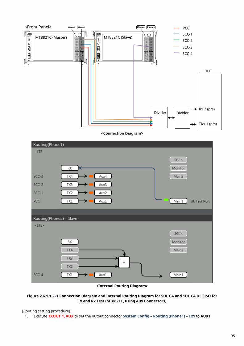
<Connection Diagram>
<Internal Routing Diagram>
Figure 2.6.1.1.2–1 Connection Diagram and Internal Routing Diagram for 5DL CA and 1UL CA DL SISO for
Tx and Rx Test (MT8821C, using Aux Connectors) [Routing setting procedure]
1. Execute TXOUT 1, AUX to set the output connector System Config – Routing (Phone1) – Tx1 to AUX1.
Rx 2 (p/s)
TRx 1 (p/s)
DUT
MT8821C (Master) MT8821C (Slave)
<Front Panel> Phone1 Phone2 Phone3 Phone4
SCC-1
SCC-2
PCC
SCC-3
Divider
SCC-4
Divider
95
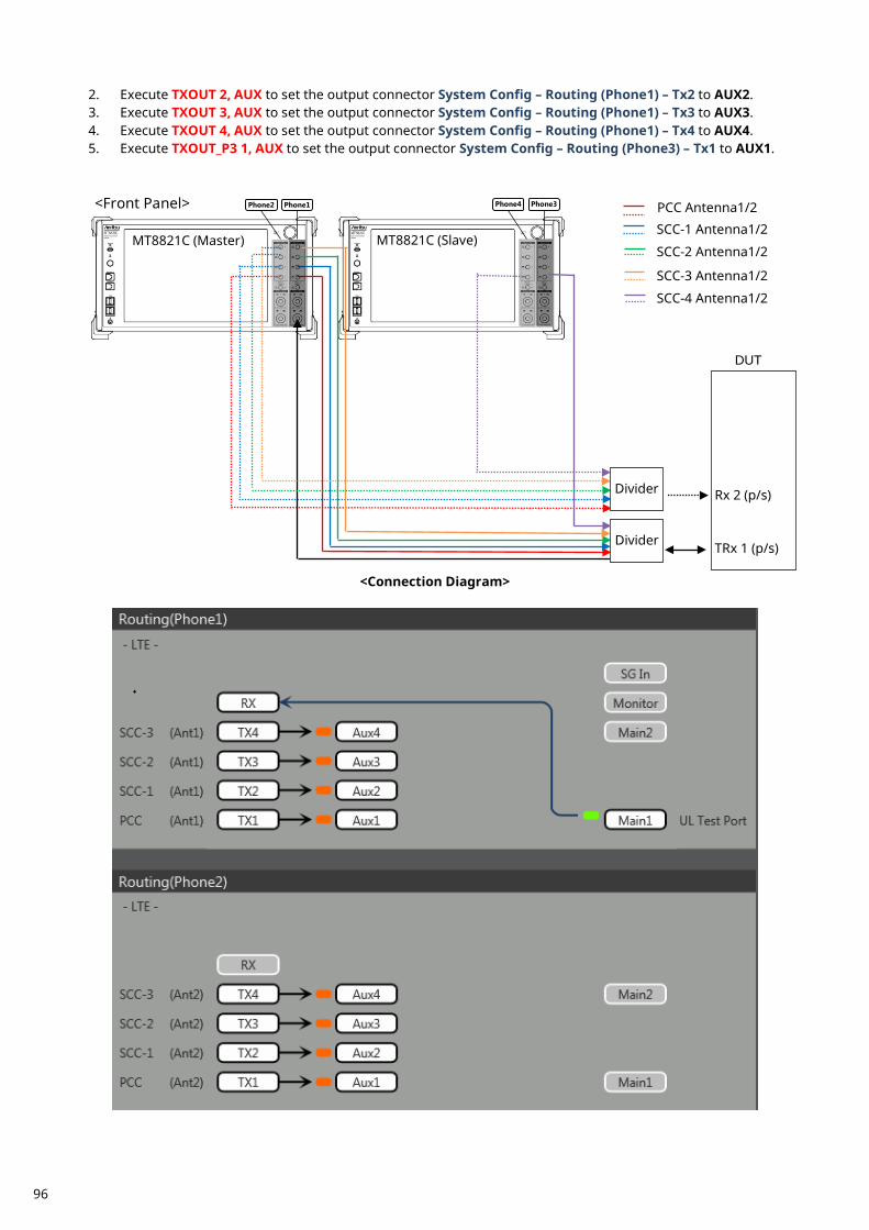
2. Execute TXOUT 2, AUX to set the output connector System Config – Routing (Phone1) – Tx2 to AUX2. 3. Execute TXOUT 3, AUX to set the output connector System Config – Routing (Phone1) – Tx3 to AUX3. 4. Execute TXOUT 4, AUX to set the output connector System Config – Routing (Phone1) – Tx4 to AUX4. 5. Execute TXOUT_P3 1, AUX to set the output connector System Config – Routing (Phone3) – Tx1 to AUX1.
<Connection Diagram>
Rx 2 (p/s)
TRx 1 (p/s)
DUT
MT8821C (Master) MT8821C (Slave)
<Front Panel> Phone1 Phone2 Phone3 Phone4
SCC-1 Antenna1/2
SCC-2 Antenna1/2
PCC Antenna1/2
SCC-3 Antenna1/2
Divider
SCC-4 Antenna1/2
Divider
96
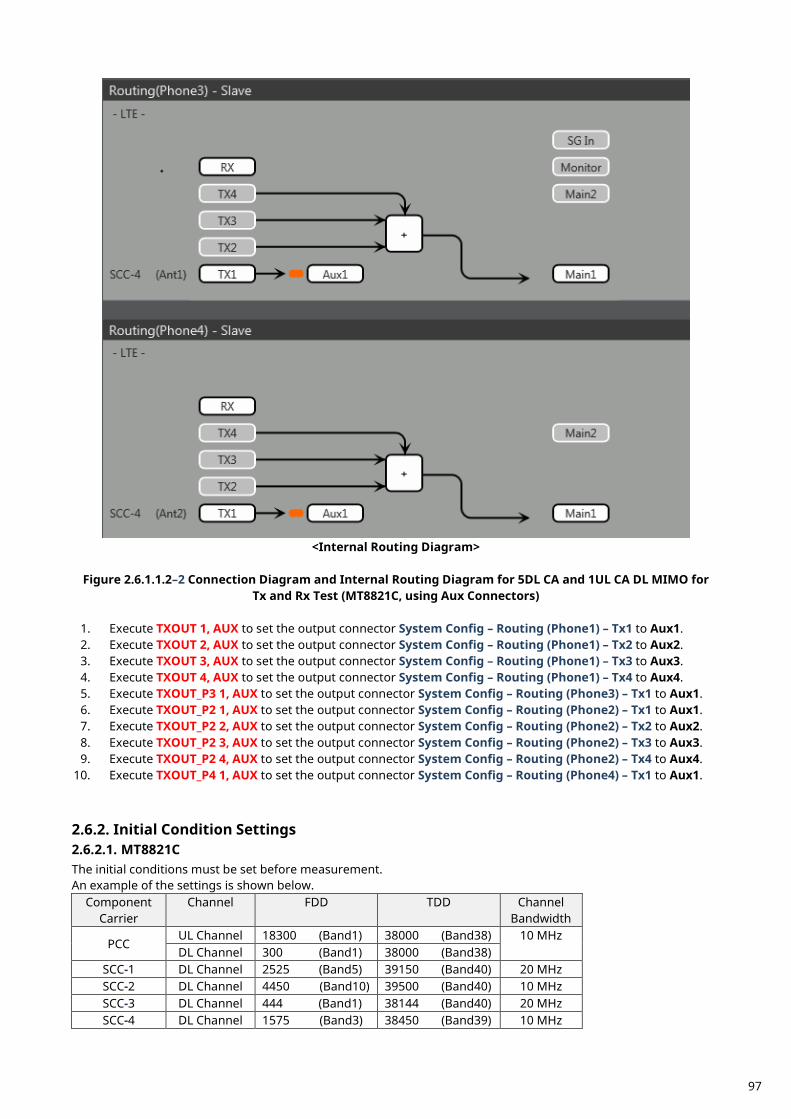
<Internal Routing Diagram>
Figure 2.6.1.1.2–2 Connection Diagram and Internal Routing Diagram for 5DL CA and 1UL CA DL MIMO for
Tx and Rx Test (MT8821C, using Aux Connectors)
1. Execute TXOUT 1, AUX to set the output connector System Config – Routing (Phone1) – Tx1 to Aux1. 2. Execute TXOUT 2, AUX to set the output connector System Config – Routing (Phone1) – Tx2 to Aux2. 3. Execute TXOUT 3, AUX to set the output connector System Config – Routing (Phone1) – Tx3 to Aux3. 4. Execute TXOUT 4, AUX to set the output connector System Config – Routing (Phone1) – Tx4 to Aux4. 5. Execute TXOUT_P3 1, AUX to set the output connector System Config – Routing (Phone3) – Tx1 to Aux1. 6. Execute TXOUT_P2 1, AUX to set the output connector System Config – Routing (Phone2) – Tx1 to Aux1. 7. Execute TXOUT_P2 2, AUX to set the output connector System Config – Routing (Phone2) – Tx2 to Aux2. 8. Execute TXOUT_P2 3, AUX to set the output connector System Config – Routing (Phone2) – Tx3 to Aux3. 9. Execute TXOUT_P2 4, AUX to set the output connector System Config – Routing (Phone2) – Tx4 to Aux4.
10. Execute TXOUT_P4 1, AUX to set the output connector System Config – Routing (Phone4) – Tx1 to Aux1.
Initial Condition Settings 2.6.2.2.6.2.1. MT8821C The initial conditions must be set before measurement. An example of the settings is shown below.
Component Carrier
Channel FDD TDD Channel Bandwidth
PCC UL Channel 18300 (Band1) 38000 (Band38) 10 MHz DL Channel 300 (Band1) 38000 (Band38)
SCC-1 DL Channel 2525 (Band5) 39150 (Band40) 20 MHz SCC-2 DL Channel 4450 (Band10) 39500 (Band40) 10 MHz SCC-3 DL Channel 444 (Band1) 38144 (Band40) 20 MHz SCC-4 DL Channel 1575 (Band3) 38450 (Band39) 10 MHz
97
2.6.2.1.1. Master-Slave Synchronization Procedure This section describes the initial procedure for synchronizing the two MT8821C units. Note: The same software version must be installed in both the MT8821C Master and Slave units. 1. Connect the cables and connectors as shown in section 9.3.21.1. 2. Load and select the LTE measurement software at Phone1/2 in the MT8821C (Master). 3. Load and select the LTE measurement software at Phone1/2 in the MT8821C (Slave). 4. Set the Master-Slave operating mode to Slave in the MT8821C (Slave) (NOTE 1). 5. Set the Master-Slave operating mode to Master in the MT8821C (Master) (NOTE 2).
NOTE 1: Set the Master-Slave operating mode at the MT8821C (Slave) before setting the Master-Slave operating mode at the MT8821C (Master).
NOTE 2: The synchronization process is performed automatically.
NOTE 3: When setting the Master-Slave operating mode to Slave, the IP addresses for the Remote 1 and Remote 2 ports are set to the following addresses automatically. When changing IP addresses for the MT8821C (Master) from the default values, do not use the following addresses.
MT8821C (Slave) IP Address
IP Address Subnet mMask Default gGateway Remote 1 192.168.20.5 255.255.255.0 192.168.20.1 Remote 2 192.168.20.6 255.255.255.0 192.168.20.1
2.6.2.1.2. Setting Example 1 (FDD)
1. Execute PRESET to set the default parameters. 2. Execute CHCODING RMC_DL_CA_PCC to set Common Parameter – Channel Coding to RMC (DL CA). 3. Execute DLSCC 4 to set Call Processing Parameter – Number of DL SCC to 4. 4. Execute CALLPROC ON to set Common Parameter – Call Processing to On. 5. Execute TXSIGSRC RT_DLSIG to set Common Parameter – Tx Signal Source to Real time generated DL
signal. <When DL 2x2 MIMO >
6. Execute ANTCONFIG OPEN_LOOP to set Common Parameter – Antenna Configuration to 2x2MIMO (Open Loop).
7. Execute DLCHAN 300 to set Common Parameter – UL Channel and DL Channel to 18300 and 300, respectively.
8. Execute DLCHAN_SCC1 2525 to set Common Parameter – SCC-1 – DL Channel to 2525. 9. Execute DLCHAN_SCC2 4450 to set Common Parameter – SCC-2 – DL Channel to 4450.
10. Execute DLCHAN_SCC3 444 to set Common Parameter – SCC-3 – DL Channel to 444. 11. Execute DLCHAN_SCC4 1575 to set Common Parameter – SCC-4 – DL Channel to 1575. 12. Execute BANDWIDTH 10MHZ to set Common Parameter - Channel Bandwidth to 10 MHz. 13. Execute BANDWIDTH_SCC1 20MHZ to set Common Parameter – SCC-1 – Channel Bandwidth to 20 MHz. 14. Execute BANDWIDTH_SCC2 10MHZ to set Common Parameter – SCC-2 – Channel Bandwidth to 10 MHz. 15. Execute BANDWIDTH_SCC3 20MHZ to set Common Parameter – SCC-3 – Channel Bandwidth to 20 MHz. 16. Execute BANDWIDTH_SCC4 10MHZ to set Common Parameter – SCC-4 – Channel Bandwidth to 10 MHz. 2.6.2.1.3. Setting Example 2 (TDD) Use the procedure described in section 2.6.2.1.2, but substitute the following steps to set the Uplink/Downlink Configuration and Special Subframe Configuration.
7. Execute DLCHAN 38000 to set Common Parameter – DL Channel and UL Channel to 38000 simultaneously.
8. Execute DLCHAN_SCC1 39150 to set Common Parameter – SCC-1 – DL Channel to 39150.
98
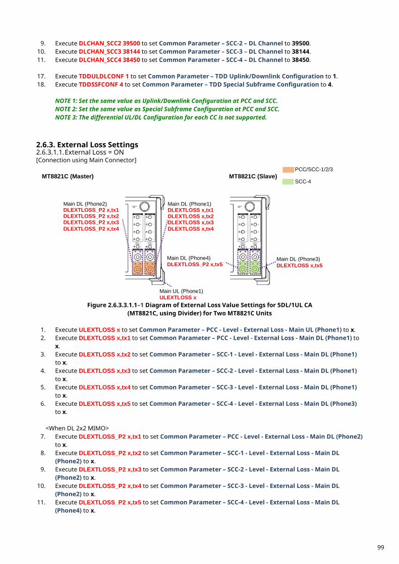
9. Execute DLCHAN_SCC2 39500 to set Common Parameter – SCC-2 – DL Channel to 39500. 10. Execute DLCHAN_SCC3 38144 to set Common Parameter – SCC-3 – DL Channel to 38144. 11. Execute DLCHAN_SCC4 38450 to set Common Parameter – SCC-4 – DL Channel to 38450. 17. Execute TDDULDLCONF 1 to set Common Parameter – TDD Uplink/Downlink Configuration to 1. 18. Execute TDDSSFCONF 4 to set Common Parameter – TDD Special Subframe Configuration to 4.
NOTE 1: Set the same value as Uplink/Downlink Configuration at PCC and SCC. NOTE 2: Set the same value as Special Subframe Configuration at PCC and SCC. NOTE 3: The differential UL/DL Configuration for each CC is not supported.
External Loss Settings 2.6.3.2.6.3.1.1. External Loss = ON [Connection using Main Connector]
Figure 2.6.3.3.1.1–1 Diagram of External Loss Value Settings for 5DL/1UL CA
(MT8821C, using Divider) for Two MT8821C Units
1. Execute ULEXTLOSS x to set Common Parameter – PCC - Level - External Loss - Main UL (Phone1) to x. 2. Execute DLEXTLOSS x,tx1 to set Common Parameter – PCC - Level - External Loss - Main DL (Phone1) to
x. 3. Execute DLEXTLOSS x,tx2 to set Common Parameter – SCC-1 - Level - External Loss - Main DL (Phone1)
to x. 4. Execute DLEXTLOSS x,tx3 to set Common Parameter – SCC-2 - Level - External Loss - Main DL (Phone1)
to x. 5. Execute DLEXTLOSS x,tx4 to set Common Parameter – SCC-3 - Level - External Loss - Main DL (Phone1)
to x. 6. Execute DLEXTLOSS x,tx5 to set Common Parameter – SCC-4 - Level - External Loss - Main DL (Phone3)
to x.
<When DL 2x2 MIMO> 7. Execute DLEXTLOSS_P2 x,tx1 to set Common Parameter – PCC - Level - External Loss - Main DL (Phone2)
to x. 8. Execute DLEXTLOSS_P2 x,tx2 to set Common Parameter – SCC-1 - Level - External Loss - Main DL
(Phone2) to x. 9. Execute DLEXTLOSS_P2 x,tx3 to set Common Parameter – SCC-2 - Level - External Loss - Main DL
(Phone2) to x. 10. Execute DLEXTLOSS_P2 x,tx4 to set Common Parameter – SCC-3 - Level - External Loss - Main DL
(Phone2) to x. 11. Execute DLEXTLOSS_P2 x,tx5 to set Common Parameter – SCC-4 - Level - External Loss - Main DL
(Phone4) to x.
MT8821C (Master) MT8821C (Slave)
Main UL (Phone1) ULEXTLOSS x
PCC/SCC-1/2/3
SCC-4
Main DL (Phone1) DLEXTLOSS x,tx1 DLEXTLOSS x,tx2 DLEXTLOSS x,tx3 DLEXTLOSS x,tx4
Main DL (Phone2) DLEXTLOSS_P2 x,tx1 DLEXTLOSS_P2 x,tx2 DLEXTLOSS_P2 x,tx3 DLEXTLOSS_P2 x,tx4
Main DL (Phone4) DLEXTLOSS_P2 x,tx5
Main DL (Phone3) DLEXTLOSS x,tx5
99
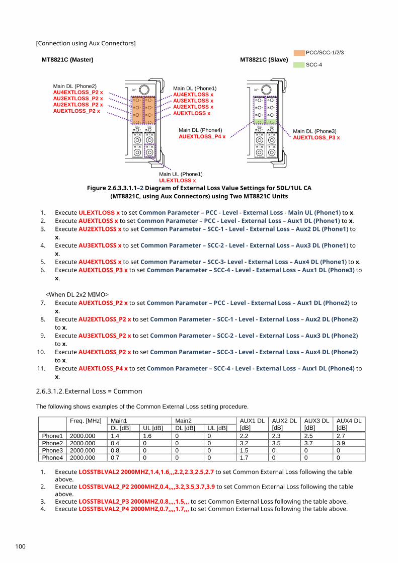
[Connection using Aux Connectors]
Figure 2.6.3.3.1.1–2 Diagram of External Loss Value Settings for 5DL/1UL CA
(MT8821C, using Aux Connectors) using Two MT8821C Units
1. Execute ULEXTLOSS x to set Common Parameter – PCC - Level - External Loss - Main UL (Phone1) to x. 2. Execute AUEXTLOSS x to set Common Parameter – PCC - Level - External Loss – Aux1 DL (Phone1) to x. 3. Execute AU2EXTLOSS x to set Common Parameter – SCC-1 - Level - External Loss – Aux2 DL (Phone1) to
x. 4. Execute AU3EXTLOSS x to set Common Parameter – SCC-2 - Level - External Loss – Aux3 DL (Phone1) to
x. 5. Execute AU4EXTLOSS x to set Common Parameter – SCC-3- Level - External Loss – Aux4 DL (Phone1) to x. 6. Execute AUEXTLOSS_P3 x to set Common Parameter – SCC-4 - Level - External Loss – Aux1 DL (Phone3) to
x.
<When DL 2x2 MIMO> 7. Execute AUEXTLOSS_P2 x to set Common Parameter – PCC - Level - External Loss – Aux1 DL (Phone2) to
x. 8. Execute AU2EXTLOSS_P2 x to set Common Parameter – SCC-1 - Level - External Loss – Aux2 DL (Phone2)
to x. 9. Execute AU3EXTLOSS_P2 x to set Common Parameter – SCC-2 - Level - External Loss – Aux3 DL (Phone2)
to x. 10. Execute AU4EXTLOSS_P2 x to set Common Parameter – SCC-3 - Level - External Loss – Aux4 DL (Phone2)
to x. 11. Execute AUEXTLOSS_P4 x to set Common Parameter – SCC-4 - Level - External Loss – Aux1 DL (Phone4) to
x. 2.6.3.1.2. External Loss = Common The following shows examples of the Common External Loss setting procedure.
Freq. [MHz] Main1 Main2 AUX1 DL [dB]
AUX2 DL [dB]
AUX3 DL [dB]
AUX4 DL [dB] DL [dB] UL [dB] DL [dB] UL [dB]
Phone1 2000.000 1.4 1.6 0 0 2.2 2.3 2.5 2.7 Phone2 2000.000 0.4 0 0 0 3.2 3.5 3.7 3.9 Phone3 2000.000 0.8 0 0 0 1.5 0 0 0 Phone4 2000.000 0.7 0 0 0 1.7 0 0 0
1. Execute LOSSTBLVAL2 2000MHZ,1.4,1.6,,,2.2,2.3,2.5,2.7 to set Common External Loss following the table
above. 2. Execute LOSSTBLVAL2_P2 2000MHZ,0.4,,,,3.2,3.5,3.7,3.9 to set Common External Loss following the table
above. 3. Execute LOSSTBLVAL2_P3 2000MHZ,0.8,,,,1.5,,, to set Common External Loss following the table above. 4. Execute LOSSTBLVAL2_P4 2000MHZ,0.7,,,,1.7,,, to set Common External Loss following the table above.
MT8821C (Master) MT8821C (Slave)
Main UL (Phone1) ULEXTLOSS x
PCC/SCC-1/2/3
SCC-4
Main DL (Phone1) AU4EXTLOSS x AU3EXTLOSS x AU2EXTLOSS x AUEXTLOSS x
Main DL (Phone2) AU4EXTLOSS_P2 x AU3EXTLOSS_P2 x AU2EXTLOSS_P2 x AUEXTLOSS_P2 x
Main DL (Phone4) AUEXTLOSS_P4 x
Main DL (Phone3) AUEXTLOSS_P3 x
100
Note: This Common External Loss value is an example.
Location Registration 2.6.4.This performs UE location registration after setting the initial conditions (2.6.2). 2.6.4.1. MT8821C
1. Connect the UE and MT8821C. 2. Execute CALLPROC ON to set Common Parameter – Call processing to ON. 3. Execute CALLSO to clear the call processing status. 4. Execute CALLSTAT? to confirm the call processing status is 1 (= Idle). 5. Turn on the UE power. 6. Execute CALLSTAT? to confirm the call processing status is 2 (= Idle (Regist)).
Repeat step 6 when the checked status is not 2 (= Idle (Regist)).
Test Mode Connection and Disconnection 2.6.5. Refer to chapter 2.1.4.
Inter-Frequency Handover 2.6.6. For SCC-4, the following steps are added to the procedure in section 2.4.5 This section describes an example for FDD. 2.6.6.1. MT8821C <Changing SCC-4 channel> 3. Execute DLCHAN_SCC4 1550 to set Common Parameter – SCC-4 – DL Channel to 1550. 4. Execute CALLSTATIC? to confirm the call processing stationary status is 6 (= Connected).
101
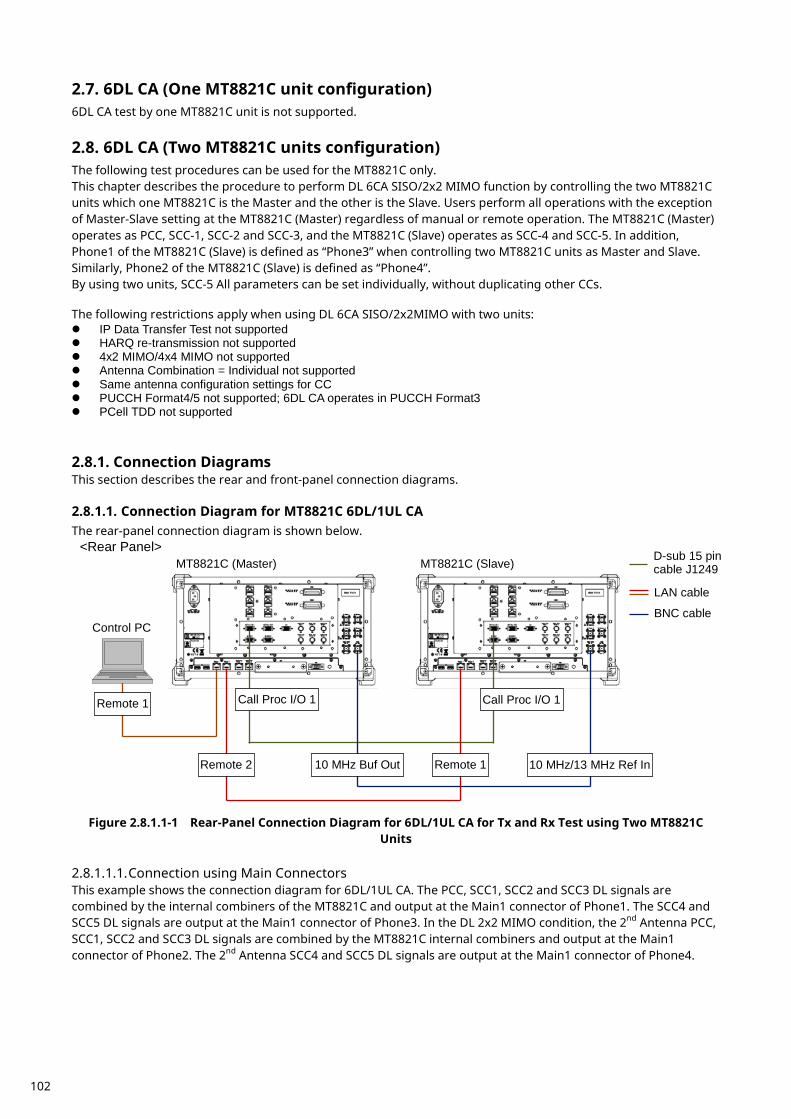
6DL CA (One MT8821C unit configuration) 2.7.6DL CA test by one MT8821C unit is not supported.
6DL CA (Two MT8821C units configuration) 2.8.The following test procedures can be used for the MT8821C only. This chapter describes the procedure to perform DL 6CA SISO/2x2 MIMO function by controlling the two MT8821C units which one MT8821C is the Master and the other is the Slave. Users perform all operations with the exception of Master-Slave setting at the MT8821C (Master) regardless of manual or remote operation. The MT8821C (Master) operates as PCC, SCC-1, SCC-2 and SCC-3, and the MT8821C (Slave) operates as SCC-4 and SCC-5. In addition, Phone1 of the MT8821C (Slave) is defined as “Phone3” when controlling two MT8821C units as Master and Slave. Similarly, Phone2 of the MT8821C (Slave) is defined as “Phone4”. By using two units, SCC-5 All parameters can be set individually, without duplicating other CCs.
The following restrictions apply when using DL 6CA SISO/2x2MIMO with two units: IP Data Transfer Test not supported HARQ re-transmission not supported 4x2 MIMO/4x4 MIMO not supported Antenna Combination = Individual not supported Same antenna configuration settings for CC PUCCH Format4/5 not supported; 6DL CA operates in PUCCH Format3 PCell TDD not supported
Connection Diagrams 2.8.1.This section describes the rear and front-panel connection diagrams. 2.8.1.1. Connection Diagram for MT8821C 6DL/1UL CA The rear-panel connection diagram is shown below.
Figure 2.8.1.1-1 Rear-Panel Connection Diagram for 6DL/1UL CA for Tx and Rx Test using Two MT8821C
Units 2.8.1.1.1. Connection using Main Connectors This example shows the connection diagram for 6DL/1UL CA. The PCC, SCC1, SCC2 and SCC3 DL signals are combined by the internal combiners of the MT8821C and output at the Main1 connector of Phone1. The SCC4 and SCC5 DL signals are output at the Main1 connector of Phone3. In the DL 2x2 MIMO condition, the 2nd Antenna PCC, SCC1, SCC2 and SCC3 DL signals are combined by the MT8821C internal combiners and output at the Main1 connector of Phone2. The 2nd Antenna SCC4 and SCC5 DL signals are output at the Main1 connector of Phone4.
MT8821C (Master) MT8821C (Slave)
Control PC
Remote 1 Call Proc I/O 1 Call Proc I/O 1
Remote 2 Remote 1 10 MHz Buf Out 10 MHz/13 MHz Ref In
<Rear Panel> D-sub 15 pin cable J1249
LAN cable
BNC cable
102
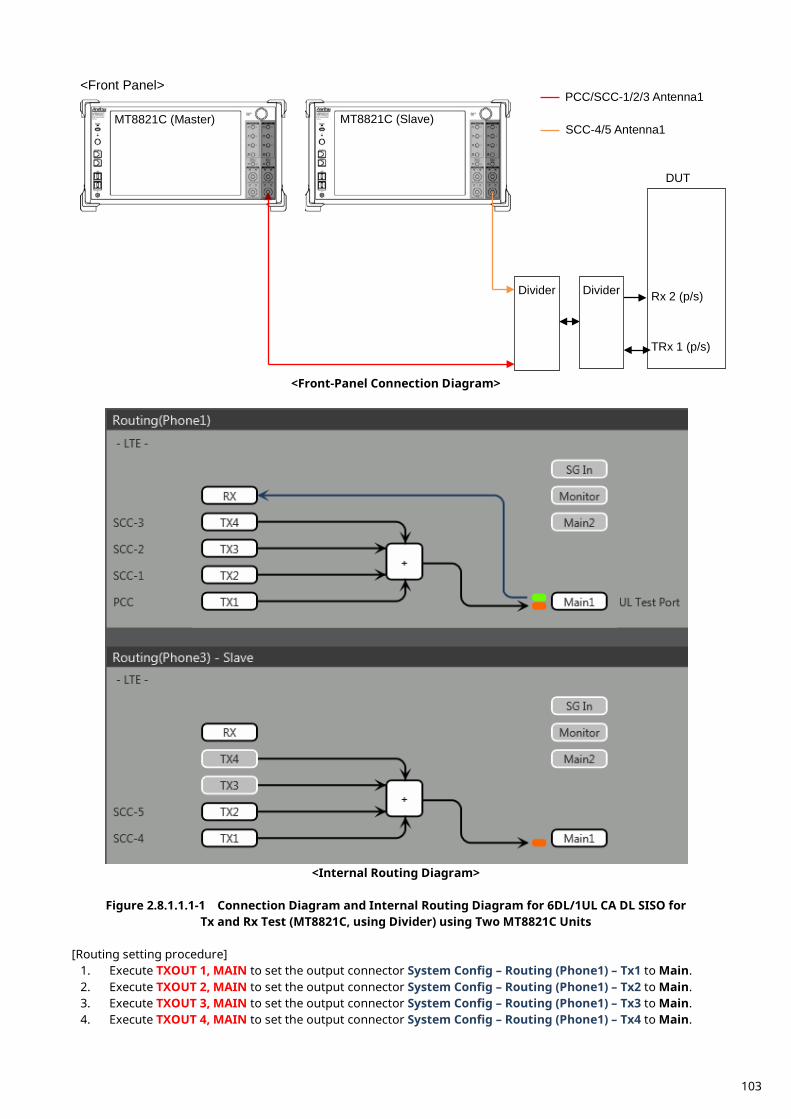
<Front-Panel Connection Diagram>
<Internal Routing Diagram>
Figure 2.8.1.1.1-1 Connection Diagram and Internal Routing Diagram for 6DL/1UL CA DL SISO for
Tx and Rx Test (MT8821C, using Divider) using Two MT8821C Units [Routing setting procedure]
1. Execute TXOUT 1, MAIN to set the output connector System Config – Routing (Phone1) – Tx1 to Main. 2. Execute TXOUT 2, MAIN to set the output connector System Config – Routing (Phone1) – Tx2 to Main. 3. Execute TXOUT 3, MAIN to set the output connector System Config – Routing (Phone1) – Tx3 to Main. 4. Execute TXOUT 4, MAIN to set the output connector System Config – Routing (Phone1) – Tx4 to Main.
Rx 2 (p/s)
TRx 1 (p/s)
DUT
Divider
MT8821C (Master) MT8821C (Slave)
<Front Panel>
SCC-4/5 Antenna1
PCC/SCC-1/2/3 Antenna1
Divider
103
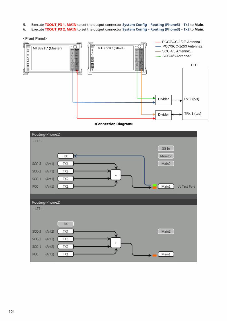
5. Execute TXOUT_P3 1, MAIN to set the output connector System Config – Routing (Phone3) – Tx1 to Main. 6. Execute TXOUT_P3 2, MAIN to set the output connector System Config – Routing (Phone3) – Tx2 to Main.
<Connection Diagram>
Rx 2 (p/s)
TRx 1 (p/s)
DUT
Divider
Divider
MT8821C (Master) MT8821C (Slave)
<Front Panel>
SCC-4/5 Antenna1 PCC/SCC-1/2/3 Antenna2 PCC/SCC-1/2/3 Antenna1
SCC-4/5 Antenna2
104
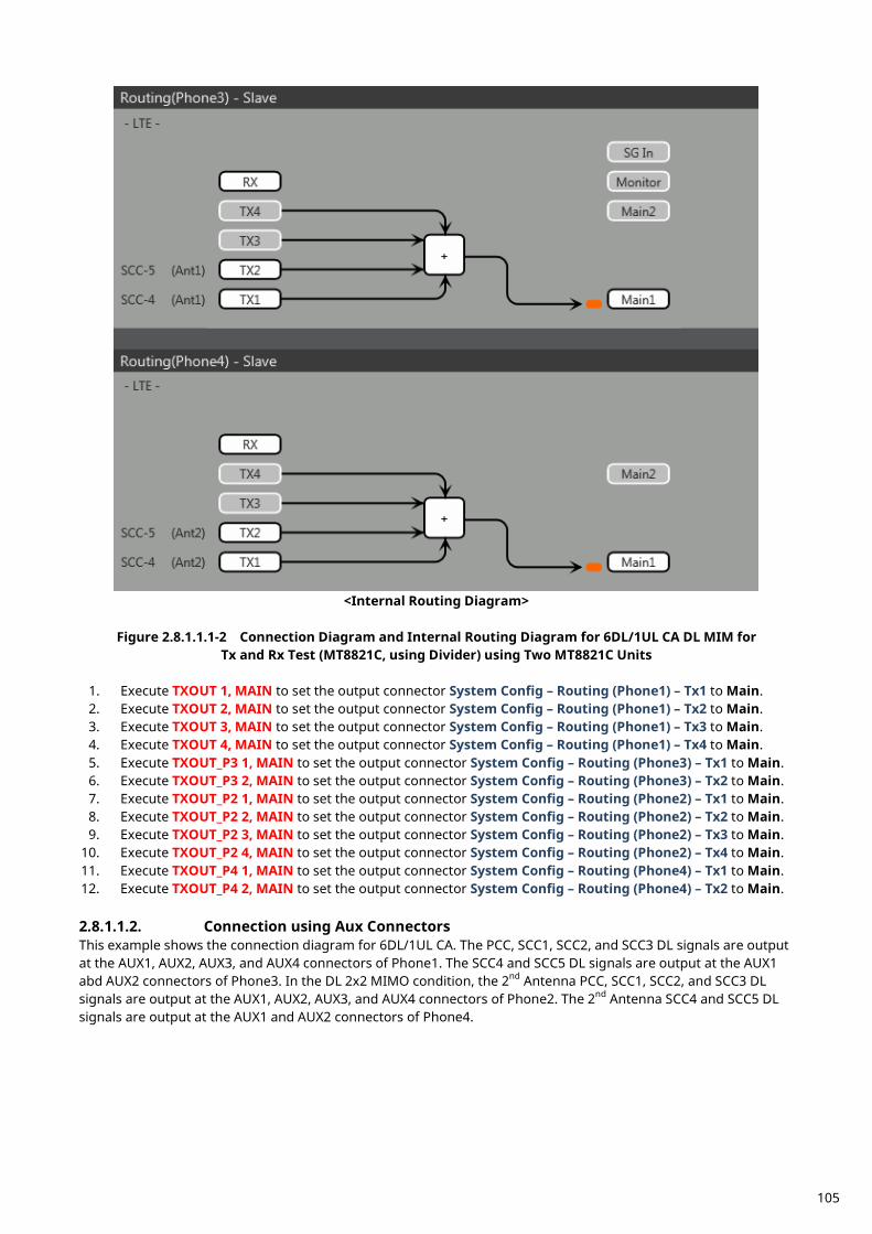
<Internal Routing Diagram>
Figure 2.8.1.1.1-2 Connection Diagram and Internal Routing Diagram for 6DL/1UL CA DL MIM for
Tx and Rx Test (MT8821C, using Divider) using Two MT8821C Units
1. Execute TXOUT 1, MAIN to set the output connector System Config – Routing (Phone1) – Tx1 to Main. 2. Execute TXOUT 2, MAIN to set the output connector System Config – Routing (Phone1) – Tx2 to Main. 3. Execute TXOUT 3, MAIN to set the output connector System Config – Routing (Phone1) – Tx3 to Main. 4. Execute TXOUT 4, MAIN to set the output connector System Config – Routing (Phone1) – Tx4 to Main. 5. Execute TXOUT_P3 1, MAIN to set the output connector System Config – Routing (Phone3) – Tx1 to Main. 6. Execute TXOUT_P3 2, MAIN to set the output connector System Config – Routing (Phone3) – Tx2 to Main. 7. Execute TXOUT_P2 1, MAIN to set the output connector System Config – Routing (Phone2) – Tx1 to Main. 8. Execute TXOUT_P2 2, MAIN to set the output connector System Config – Routing (Phone2) – Tx2 to Main. 9. Execute TXOUT_P2 3, MAIN to set the output connector System Config – Routing (Phone2) – Tx3 to Main.
10. Execute TXOUT_P2 4, MAIN to set the output connector System Config – Routing (Phone2) – Tx4 to Main. 11. Execute TXOUT_P4 1, MAIN to set the output connector System Config – Routing (Phone4) – Tx1 to Main. 12. Execute TXOUT_P4 2, MAIN to set the output connector System Config – Routing (Phone4) – Tx2 to Main. 2.8.1.1.2. Connection using Aux Connectors This example shows the connection diagram for 6DL/1UL CA. The PCC, SCC1, SCC2, and SCC3 DL signals are output at the AUX1, AUX2, AUX3, and AUX4 connectors of Phone1. The SCC4 and SCC5 DL signals are output at the AUX1 abd AUX2 connectors of Phone3. In the DL 2x2 MIMO condition, the 2nd Antenna PCC, SCC1, SCC2, and SCC3 DL signals are output at the AUX1, AUX2, AUX3, and AUX4 connectors of Phone2. The 2nd Antenna SCC4 and SCC5 DL signals are output at the AUX1 and AUX2 connectors of Phone4.
105
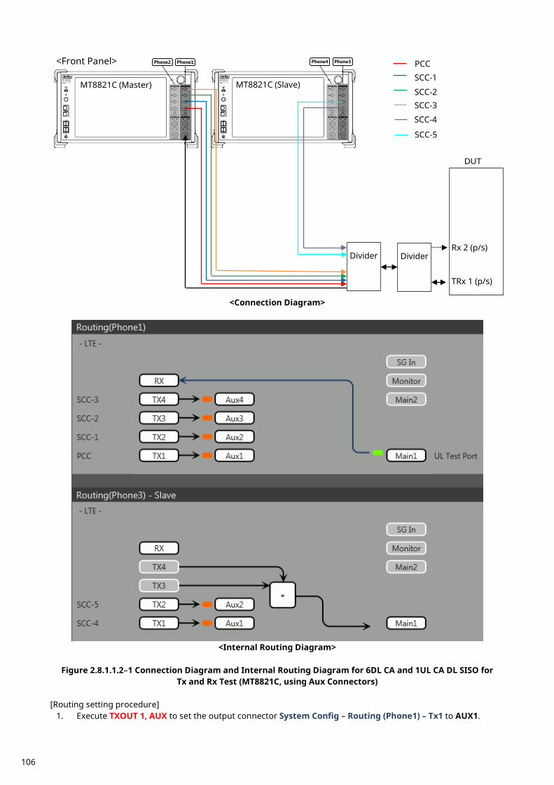
<Connection Diagram>
<Internal Routing Diagram>
Figure 2.8.1.1.2–1 Connection Diagram and Internal Routing Diagram for 6DL CA and 1UL CA DL SISO for
Tx and Rx Test (MT8821C, using Aux Connectors) [Routing setting procedure]
1. Execute TXOUT 1, AUX to set the output connector System Config – Routing (Phone1) – Tx1 to AUX1.
Rx 2 (p/s)
TRx 1 (p/s)
DUT
MT8821C (Master) MT8821C (Slave)
<Front Panel> Phone1 Phone2 Phone3 Phone4
SCC-1
SCC-2
PCC
SCC-3
Divider
SCC-4
Divider
SCC-5
106
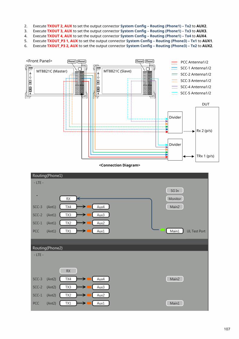
2. Execute TXOUT 2, AUX to set the output connector System Config – Routing (Phone1) – Tx2 to AUX2. 3. Execute TXOUT 3, AUX to set the output connector System Config – Routing (Phone1) – Tx3 to AUX3. 4. Execute TXOUT 4, AUX to set the output connector System Config – Routing (Phone1) – Tx4 to AUX4. 5. Execute TXOUT_P3 1, AUX to set the output connector System Config – Routing (Phone3) – Tx1 to AUX1. 6. Execute TXOUT_P3 2, AUX to set the output connector System Config – Routing (Phone3) – Tx2 to AUX2.
<Connection Diagram>
Rx 2 (p/s)
TRx 1 (p/s)
DUT
MT8821C (Master) MT8821C (Slave)
<Front Panel> Phone1 Phone2 Phone3 Phone4
SCC-1 Antenna1/2
SCC-2 Antenna1/2
PCC Antenna1/2
SCC-3 Antenna1/2 SCC-4 Antenna1/2
Divider
SCC-5 Antenna1/2
Divider
107
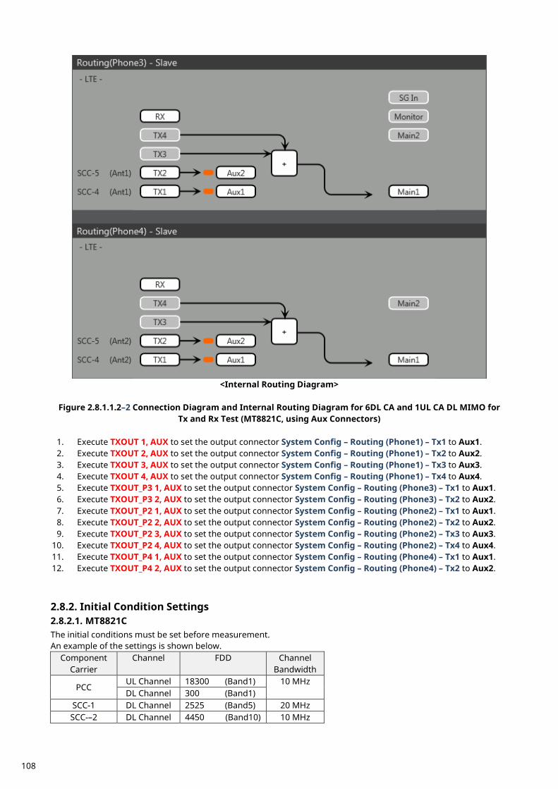
<Internal Routing Diagram>
Figure 2.8.1.1.2–2 Connection Diagram and Internal Routing Diagram for 6DL CA and 1UL CA DL MIMO for
Tx and Rx Test (MT8821C, using Aux Connectors)
1. Execute TXOUT 1, AUX to set the output connector System Config – Routing (Phone1) – Tx1 to Aux1. 2. Execute TXOUT 2, AUX to set the output connector System Config – Routing (Phone1) – Tx2 to Aux2. 3. Execute TXOUT 3, AUX to set the output connector System Config – Routing (Phone1) – Tx3 to Aux3. 4. Execute TXOUT 4, AUX to set the output connector System Config – Routing (Phone1) – Tx4 to Aux4. 5. Execute TXOUT_P3 1, AUX to set the output connector System Config – Routing (Phone3) – Tx1 to Aux1. 6. Execute TXOUT_P3 2, AUX to set the output connector System Config – Routing (Phone3) – Tx2 to Aux2. 7. Execute TXOUT_P2 1, AUX to set the output connector System Config – Routing (Phone2) – Tx1 to Aux1. 8. Execute TXOUT_P2 2, AUX to set the output connector System Config – Routing (Phone2) – Tx2 to Aux2. 9. Execute TXOUT_P2 3, AUX to set the output connector System Config – Routing (Phone2) – Tx3 to Aux3.
10. Execute TXOUT_P2 4, AUX to set the output connector System Config – Routing (Phone2) – Tx4 to Aux4. 11. Execute TXOUT_P4 1, AUX to set the output connector System Config – Routing (Phone4) – Tx1 to Aux1. 12. Execute TXOUT_P4 2, AUX to set the output connector System Config – Routing (Phone4) – Tx2 to Aux2.
Initial Condition Settings 2.8.2.2.8.2.1. MT8821C The initial conditions must be set before measurement. An example of the settings is shown below.
Component Carrier
Channel FDD Channel Bandwidth
PCC UL Channel 18300 (Band1) 10 MHz DL Channel 300 (Band1)
SCC-1 DL Channel 2525 (Band5) 20 MHz SCC-–2 DL Channel 4450 (Band10) 10 MHz
108
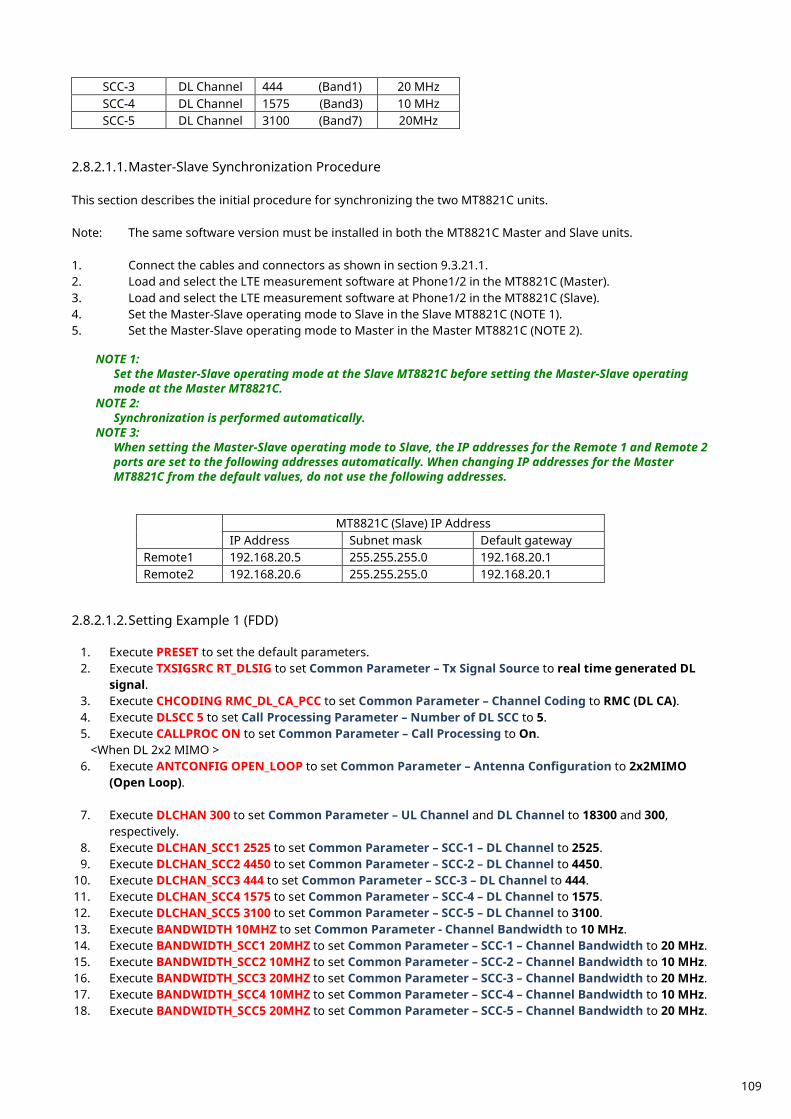
SCC-3 DL Channel 444 (Band1) 20 MHz SCC-4 DL Channel 1575 (Band3) 10 MHz SCC-5 DL Channel 3100 (Band7) 20MHz
2.8.2.1.1. Master-Slave Synchronization Procedure This section describes the initial procedure for synchronizing the two MT8821C units. Note: The same software version must be installed in both the MT8821C Master and Slave units. 1. Connect the cables and connectors as shown in section 9.3.21.1. 2. Load and select the LTE measurement software at Phone1/2 in the MT8821C (Master). 3. Load and select the LTE measurement software at Phone1/2 in the MT8821C (Slave). 4. Set the Master-Slave operating mode to Slave in the Slave MT8821C (NOTE 1). 5. Set the Master-Slave operating mode to Master in the Master MT8821C (NOTE 2).
NOTE 1: Set the Master-Slave operating mode at the Slave MT8821C before setting the Master-Slave operating mode at the Master MT8821C.
NOTE 2: Synchronization is performed automatically.
NOTE 3: When setting the Master-Slave operating mode to Slave, the IP addresses for the Remote 1 and Remote 2 ports are set to the following addresses automatically. When changing IP addresses for the Master MT8821C from the default values, do not use the following addresses.
MT8821C (Slave) IP Address IP Address Subnet mask Default gateway
Remote1 192.168.20.5 255.255.255.0 192.168.20.1 Remote2 192.168.20.6 255.255.255.0 192.168.20.1
2.8.2.1.2. Setting Example 1 (FDD)
1. Execute PRESET to set the default parameters. 2. Execute TXSIGSRC RT_DLSIG to set Common Parameter – Tx Signal Source to real time generated DL
signal. 3. Execute CHCODING RMC_DL_CA_PCC to set Common Parameter – Channel Coding to RMC (DL CA). 4. Execute DLSCC 5 to set Call Processing Parameter – Number of DL SCC to 5. 5. Execute CALLPROC ON to set Common Parameter – Call Processing to On.
<When DL 2x2 MIMO > 6. Execute ANTCONFIG OPEN_LOOP to set Common Parameter – Antenna Configuration to 2x2MIMO
(Open Loop).
7. Execute DLCHAN 300 to set Common Parameter – UL Channel and DL Channel to 18300 and 300, respectively.
8. Execute DLCHAN_SCC1 2525 to set Common Parameter – SCC-1 – DL Channel to 2525. 9. Execute DLCHAN_SCC2 4450 to set Common Parameter – SCC-2 – DL Channel to 4450.
10. Execute DLCHAN_SCC3 444 to set Common Parameter – SCC-3 – DL Channel to 444. 11. Execute DLCHAN_SCC4 1575 to set Common Parameter – SCC-4 – DL Channel to 1575. 12. Execute DLCHAN_SCC5 3100 to set Common Parameter – SCC-5 – DL Channel to 3100. 13. Execute BANDWIDTH 10MHZ to set Common Parameter - Channel Bandwidth to 10 MHz. 14. Execute BANDWIDTH_SCC1 20MHZ to set Common Parameter – SCC-1 – Channel Bandwidth to 20 MHz. 15. Execute BANDWIDTH_SCC2 10MHZ to set Common Parameter – SCC-2 – Channel Bandwidth to 10 MHz. 16. Execute BANDWIDTH_SCC3 20MHZ to set Common Parameter – SCC-3 – Channel Bandwidth to 20 MHz. 17. Execute BANDWIDTH_SCC4 10MHZ to set Common Parameter – SCC-4 – Channel Bandwidth to 10 MHz. 18. Execute BANDWIDTH_SCC5 20MHZ to set Common Parameter – SCC-5 – Channel Bandwidth to 20 MHz.
109
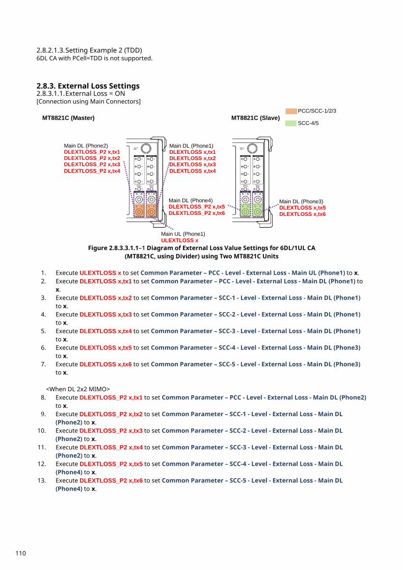
2.8.2.1.3. Setting Example 2 (TDD) 6DL CA with PCell=TDD is not supported.
External Loss Settings 2.8.3.2.8.3.1.1. External Loss = ON [Connection using Main Connectors]
Figure 2.8.3.3.1.1–1 Diagram of External Loss Value Settings for 6DL/1UL CA
(MT8821C, using Divider) using Two MT8821C Units
1. Execute ULEXTLOSS x to set Common Parameter – PCC - Level - External Loss - Main UL (Phone1) to x. 2. Execute DLEXTLOSS x,tx1 to set Common Parameter – PCC - Level - External Loss - Main DL (Phone1) to
x. 3. Execute DLEXTLOSS x,tx2 to set Common Parameter – SCC-1 - Level - External Loss - Main DL (Phone1)
to x. 4. Execute DLEXTLOSS x,tx3 to set Common Parameter – SCC-2 - Level - External Loss - Main DL (Phone1)
to x. 5. Execute DLEXTLOSS x,tx4 to set Common Parameter – SCC-3 - Level - External Loss - Main DL (Phone1)
to x. 6. Execute DLEXTLOSS x,tx5 to set Common Parameter – SCC-4 - Level - External Loss - Main DL (Phone3)
to x. 7. Execute DLEXTLOSS x,tx6 to set Common Parameter – SCC-5 - Level - External Loss - Main DL (Phone3)
to x.
<When DL 2x2 MIMO> 8. Execute DLEXTLOSS_P2 x,tx1 to set Common Parameter – PCC - Level - External Loss - Main DL (Phone2)
to x. 9. Execute DLEXTLOSS_P2 x,tx2 to set Common Parameter – SCC-1 - Level - External Loss - Main DL
(Phone2) to x. 10. Execute DLEXTLOSS_P2 x,tx3 to set Common Parameter – SCC-2 - Level - External Loss - Main DL
(Phone2) to x. 11. Execute DLEXTLOSS_P2 x,tx4 to set Common Parameter – SCC-3 - Level - External Loss - Main DL
(Phone2) to x. 12. Execute DLEXTLOSS_P2 x,tx5 to set Common Parameter – SCC-4 - Level - External Loss - Main DL
(Phone4) to x. 13. Execute DLEXTLOSS_P2 x,tx6 to set Common Parameter – SCC-5 - Level - External Loss - Main DL
(Phone4) to x.
MT8821C (Master) MT8821C (Slave)
Main UL (Phone1) ULEXTLOSS x
PCC/SCC-1/2/3
SCC-4/5
Main DL (Phone1) DLEXTLOSS x,tx1 DLEXTLOSS x,tx2 DLEXTLOSS x,tx3 DLEXTLOSS x,tx4
Main DL (Phone2) DLEXTLOSS_P2 x,tx1 DLEXTLOSS_P2 x,tx2 DLEXTLOSS_P2 x,tx3 DLEXTLOSS_P2 x,tx4
Main DL (Phone4) DLEXTLOSS_P2 x,tx5 DLEXTLOSS_P2 x,tx6
Main DL (Phone3) DLEXTLOSS x,tx5 DLEXTLOSS x,tx6
110
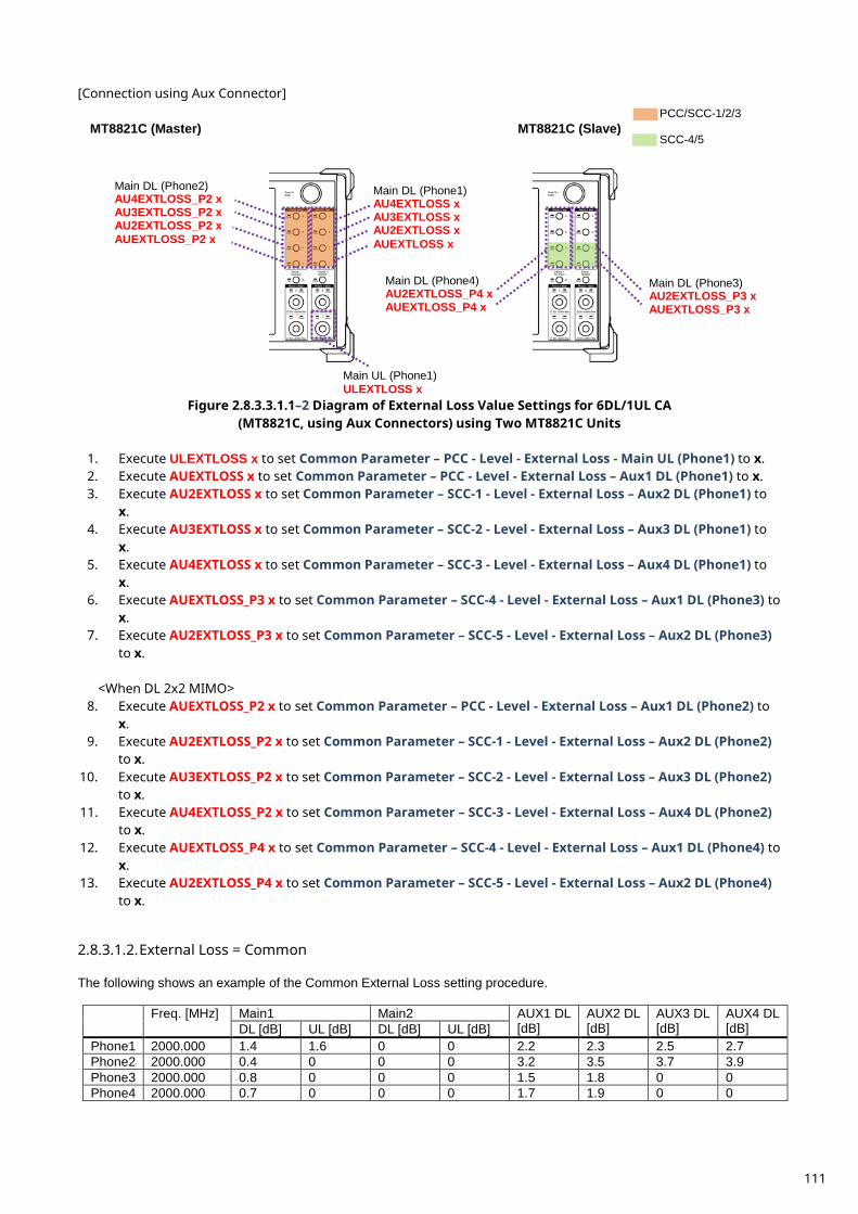
[Connection using Aux Connector]
Figure 2.8.3.3.1.1–2 Diagram of External Loss Value Settings for 6DL/1UL CA
(MT8821C, using Aux Connectors) using Two MT8821C Units
1. Execute ULEXTLOSS x to set Common Parameter – PCC - Level - External Loss - Main UL (Phone1) to x. 2. Execute AUEXTLOSS x to set Common Parameter – PCC - Level - External Loss – Aux1 DL (Phone1) to x. 3. Execute AU2EXTLOSS x to set Common Parameter – SCC-1 - Level - External Loss – Aux2 DL (Phone1) to
x. 4. Execute AU3EXTLOSS x to set Common Parameter – SCC-2 - Level - External Loss – Aux3 DL (Phone1) to
x. 5. Execute AU4EXTLOSS x to set Common Parameter – SCC-3 - Level - External Loss – Aux4 DL (Phone1) to
x. 6. Execute AUEXTLOSS_P3 x to set Common Parameter – SCC-4 - Level - External Loss – Aux1 DL (Phone3) to
x. 7. Execute AU2EXTLOSS_P3 x to set Common Parameter – SCC-5 - Level - External Loss – Aux2 DL (Phone3)
to x.
<When DL 2x2 MIMO> 8. Execute AUEXTLOSS_P2 x to set Common Parameter – PCC - Level - External Loss – Aux1 DL (Phone2) to
x. 9. Execute AU2EXTLOSS_P2 x to set Common Parameter – SCC-1 - Level - External Loss – Aux2 DL (Phone2)
to x. 10. Execute AU3EXTLOSS_P2 x to set Common Parameter – SCC-2 - Level - External Loss – Aux3 DL (Phone2)
to x. 11. Execute AU4EXTLOSS_P2 x to set Common Parameter – SCC-3 - Level - External Loss – Aux4 DL (Phone2)
to x. 12. Execute AUEXTLOSS_P4 x to set Common Parameter – SCC-4 - Level - External Loss – Aux1 DL (Phone4) to
x. 13. Execute AU2EXTLOSS_P4 x to set Common Parameter – SCC-5 - Level - External Loss – Aux2 DL (Phone4)
to x. 2.8.3.1.2. External Loss = Common The following shows an example of the Common External Loss setting procedure.
Freq. [MHz] Main1 Main2 AUX1 DL [dB]
AUX2 DL [dB]
AUX3 DL [dB]
AUX4 DL [dB] DL [dB] UL [dB] DL [dB] UL [dB]
Phone1 2000.000 1.4 1.6 0 0 2.2 2.3 2.5 2.7 Phone2 2000.000 0.4 0 0 0 3.2 3.5 3.7 3.9 Phone3 2000.000 0.8 0 0 0 1.5 1.8 0 0 Phone4 2000.000 0.7 0 0 0 1.7 1.9 0 0
MT8821C (Master) MT8821C (Slave)
Main UL (Phone1) ULEXTLOSS x
PCC/SCC-1/2/3
SCC-4/5
Main DL (Phone1) AU4EXTLOSS x AU3EXTLOSS x AU2EXTLOSS x AUEXTLOSS x
Main DL (Phone2) AU4EXTLOSS_P2 x AU3EXTLOSS_P2 x AU2EXTLOSS_P2 x AUEXTLOSS_P2 x
Main DL (Phone4) AU2EXTLOSS_P4 x AUEXTLOSS_P4 x
Main DL (Phone3) AU2EXTLOSS_P3 x AUEXTLOSS_P3 x
111
1. Execute LOSSTBLVAL2 2000MHZ,1.4,1.6,,,2.2,2.3,2.5,2.7 to set Common External Loss following the table above.
2. Execute LOSSTBLVAL2_P2 2000MHZ,0.4,,,,3.2,3.5,3.7,3.9 to set Common External Loss following the table above.
3. Execute LOSSTBLVAL2_P3 2000MHZ,0.8,,,,1.5,1.8,, to set Common External Loss following the table above. 4. Execute LOSSTBLVAL2_P4 2000MHZ,0.7,,,,1.7,1.9,, to set Common External Loss following the table above.
Note: This Common External Loss value is an example.
Location Registration 2.8.4.This performs UE location registration after setting the initial conditions (2.8.2). 2.8.4.1. MT8821C
1. Connect the UE and MT8821C. 2. Execute CALLPROC ON to set Common Parameter – Call processing to ON. 3. Execute CALLSO to clear the call processing status. 4. Execute CALLSTAT? to confirm the call processing status is 1 (= Idle). 5. Turn on the UE power. 6. Execute CALLSTAT? to confirm the call processing status is 2 (= Idle (Regist)).
Repeat step 6 when the checked status is not 2 (= Idle (Regist)).
Test Mode Connection and Disconnection 2.8.5. Refer to section 2.1.4.
Inter-Frequency Handover 2.8.6. For SCC-5, the following steps are added to the procedure in section 2.4.5 This section describes an example for FDD. 2.8.6.1. MT8821C <Changing SCC-5 channel> 1. Execute DLCHAN_SCC5 3298 to set Common Parameter – SCC-5 – DL Channel to 3298. 2. Execute CALLSTATIC? to confirm the call processing stationary status is 6 (= Connected).
112
TRX Measurements (Fundamental Measurements) 3. This chapter describes how to test TRX measurement using GPIB remote control software commands. For details of GPIB commands and manual operation, refer to the LTE operation manual. GPIB commands are in red bold. At Normal UE, the UE power class is assumed to be Class3. At HPUE, the UE power class is assumed to be Class1. Before starting TRX measurement, do the following to ensure the call processing status is connected.
1. Initial Condition Setting(2.1.2) 2. Broadcast Information Update(2.1.5) 3. Location registration(2.1.3) 4. Test Mode Connection(2.1.4)
Then, set the average count for each measurement items to 20 times, except for special conditions.
TX Measurements 3.1.The following test procedures can be used for both the MT8820C and MT8821C.
UE Maximum Output Power (6.2.2) 3.1.1. This chapter describes UL measurement examples where (Modulation, RB) is (QPSK, 1), or (QPSK, PartialRB) [Pass/Fail evaluation limits value setting]
1. Execute PWR_AVG 20 to set the average count of power measurement to 20 times. 2. Execute TP_MAXPWR_LL 20.3 to set TX1 - Max. Power (QPSK/1RB/PartialRB) Pass/Fail lower limit to 20.3 dBm. 3. Execute TP_MAXPWR_UL 25.7 to set TX1 - Max. Power (QPSK/1RB/PartialRB) Pass/Fail upper limit to 25.7 dBm.
[(QPSK, 1RB) measurements]
4. Execute TESTPRM TX_MAXPWR_Q_1 to set Test Parameter to TX1 - Max. Power (QPSK/1RB). 5. Execute ULRB_POS MIN to set UL RB Position to Min (#0). 6. Execute SWP to measure the power. 7. Execute POWER? AVG to read the TX power measurement result. 8. Execute POWERPASS? to check that the TX power measurement Pass/Fail judgment is Pass. 9. Execute ULRB_POS MAX to set UL RB Position to Max (#max).
10. Execute steps 6 to 8. [(QPSK, PartialRB) measurements]
4. Execute TESTPRM TX_MAXPWR_Q_P to set Test Parameter to TX1 - Max. Power (QPSK/PartialRB). 5. Execute steps 5 to 9.
NOTE 1: At 1RB allocation, Min (#0), Mid (#Nrb/2), and Max (#max) used in this application note
each correspond to RB #0, RB #[NRBUL/2] and RB #max, respectively, described in TS 36.521-1.
NOTE 2: At PartialRB allocation Min (#0) and Max (#max) used in this application note
each correspond to RB #0 and RB# (max +1 - RB allocation),respectively, described in TS 36.521-1.
NOTE 3: The 1RB allocation UL RB Position is divided as follows: When BWChannel > TC, Min (#0) and Max (#max) When BWChannel – TC, Min (#0) When BWChannel = (FUL_high - FUL_low), Min (#0), Mid (#Nrb/2) and Max (#max)
NOTE 4: The UL RB Position of PartialRB allocation is Min (#0).
NOTE 5: The usual Pass/Fail evaluation value is set to the Band 1 default value described in TS36.521-1. Since the evaluation value differs according to the Band, set the evaluation value described in
TS36.521-1 Table 6.2.2.5-1 at: •TP_MAXPWR_LL •TP_MAXPWR_UL For the Pass/Fail evaluation values, refer to Chapter 3.7.4 Test Parameter Limit in MT8820C operation manual or Chapter 2.9.4 Test Parameter Limit in MT8821C operation manual.
113
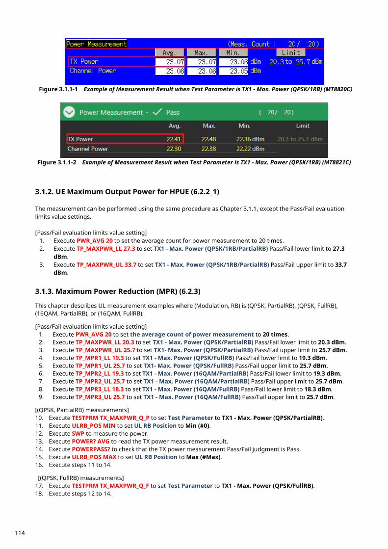
Figure 3.1.1-1 Example of Measurement Result when Test Parameter is TX1 - Max. Power (QPSK/1RB) (MT8820C)
Figure 3.1.1-2 Example of Measurement Result when Test Parameter is TX1 - Max. Power (QPSK/1RB) (MT8821C)
UE Maximum Output Power for HPUE (6.2.2_1) 3.1.2. The measurement can be performed using the same procedure as Chapter 3.1.1, except the Pass/Fail evaluation limits value settings. [Pass/Fail evaluation limits value setting]
1. Execute PWR_AVG 20 to set the average count for power measurement to 20 times. 2. Execute TP_MAXPWR_LL 27.3 to set TX1 - Max. Power (QPSK/1RB/PartialRB) Pass/Fail lower limit to 27.3
dBm. 3. Execute TP_MAXPWR_UL 33.7 to set TX1 - Max. Power (QPSK/1RB/PartialRB) Pass/Fail upper limit to 33.7
dBm.
Maximum Power Reduction (MPR) (6.2.3) 3.1.3. This chapter describes UL measurement examples where (Modulation, RB) is (QPSK, PartialRB), (QPSK, FullRB), (16QAM, PartialRB), or (16QAM, FullRB). [Pass/Fail evaluation limits value setting]
1. Execute PWR_AVG 20 to set the average count of power measurement to 20 times. 2. Execute TP_MAXPWR_LL 20.3 to set TX1 - Max. Power (QPSK/PartialRB) Pass/Fail lower limit to 20.3 dBm. 3. Execute TP_MAXPWR_UL 25.7 to set TX1- Max. Power (QPSK/PartialRB) Pass/Fail upper limit to 25.7 dBm. 4. Execute TP_MPR1_LL 19.3 to set TX1 - Max. Power (QPSK/FullRB) Pass/Fail lower limit to 19.3 dBm. 5. Execute TP_MPR1_UL 25.7 to set TX1- Max. Power (QPSK/FullRB) Pass/Fail upper limit to 25.7 dBm. 6. Execute TP_MPR2_LL 19.3 to set TX1 - Max. Power (16QAM/PartialRB) Pass/Fail lower limit to 19.3 dBm. 7. Execute TP_MPR2_UL 25.7 to set TX1 - Max. Power (16QAM/PartialRB) Pass/Fail upper limit to 25.7 dBm. 8. Execute TP_MPR3_LL 18.3 to set TX1 - Max. Power (16QAM/FullRB) Pass/Fail lower limit to 18.3 dBm. 9. Execute TP_MPR3_UL 25.7 to set TX1 - Max. Power (16QAM/FullRB) Pass/Fail upper limit to 25.7 dBm.
[(QPSK, PartialRB) measurements] 10. Execute TESTPRM TX_MAXPWR_Q_P to set Test Parameter to TX1 - Max. Power (QPSK/PartialRB). 11. Execute ULRB_POS MIN to set UL RB Position to Min (#0). 12. Execute SWP to measure the power. 13. Execute POWER? AVG to read the TX power measurement result. 14. Execute POWERPASS? to check that the TX power measurement Pass/Fail judgment is Pass. 15. Execute ULRB_POS MAX to set UL RB Position to Max (#Max). 16. Execute steps 11 to 14. [(QPSK, FullRB) measurements] 17. Execute TESTPRM TX_MAXPWR_Q_F to set Test Parameter to TX1 - Max. Power (QPSK/FullRB). 18. Execute steps 12 to 14.
114
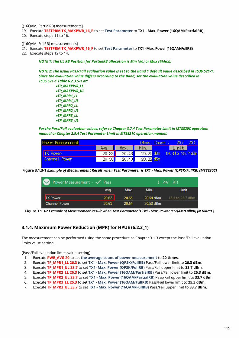
[(16QAM, PartialRB) measurements] 19. Execute TESTPRM TX_MAXPWR_16_P to set Test Parameter to TX1 - Max. Power (16QAM/PartialRB). 20. Execute steps 11 to 16. [(16QAM, FullRB) measurements] 21. Execute TESTPRM TX_MAXPWR_16_F to set Test Parameter to TX1 - Max. Power (16QAM/FullRB). 22. Execute steps 12 to 14. NOTE 1: The UL RB Position for PartialRB allocation is Min (#0) or Max (#Max).
NOTE 2: The usual Pass/Fail evaluation value is set to the Band 1 default value described in TS36.521-1. Since the evaluation value differs according to the Band, set the evaluation value described in TS36.521-1 Table 6.2.3.5-1 at:
•TP_MAXPWR_LL •TP_MAXPWR_UL •TP_MPR1_LL •TP_MPR1_UL •TP_MPR2_LL •TP_MPR2_UL •TP_MPR3_LL •TP_MPR3_UL
For the Pass/Fail evaluation values, refer to Chapter 3.7.4 Test Parameter Limit in MT8820C operation manual or Chapter 2.9.4 Test Parameter Limit in MT8821C operation manual.
Figure 3.1.3-1 Example of Measurement Result when Test Parameter is TX1 - Max. Power (QPSK/FullRB) (MT8820C)
Figure 3.1.3-2 Example of Measurement Result when Test Parameter is TX1 - Max. Power (16QAM/FullRB) (MT8821C)
Maximum Power Reduction (MPR) for HPUE (6.2.3_1) 3.1.4. The measurement can be performed using the same procedure as Chapter 3.1.3 except the Pass/Fail evaluation limits value setting. [Pass/Fail evaluation limits value setting]
1. Execute PWR_AVG 20 to set the average count of power measurement to 20 times. 2. Execute TP_MPR1_LL 26.3 to set TX1 - Max. Power (QPSK/FullRB) Pass/Fail lower limit to 26.3 dBm. 3. Execute TP_MPR1_UL 33.7 to set TX1- Max. Power (QPSK/FullRB) Pass/Fail upper limit to 33.7 dBm. 4. Execute TP_MPR2_LL 26.3 to set TX1 - Max. Power (16QAM/PartialRB) Pass/Fail lower limit to 26.3 dBm. 5. Execute TP_MPR2_UL 33.7 to set TX1 - Max. Power (16QAM/PartialRB) Pass/Fail upper limit to 33.7 dBm. 6. Execute TP_MPR3_LL 25.3 to set TX1 - Max. Power (16QAM/FullRB) Pass/Fail lower limit to 25.3 dBm. 7. Execute TP_MPR3_UL 33.7 to set TX1 - Max. Power (16QAM/FullRB) Pass/Fail upper limit to 33.7 dBm.
115
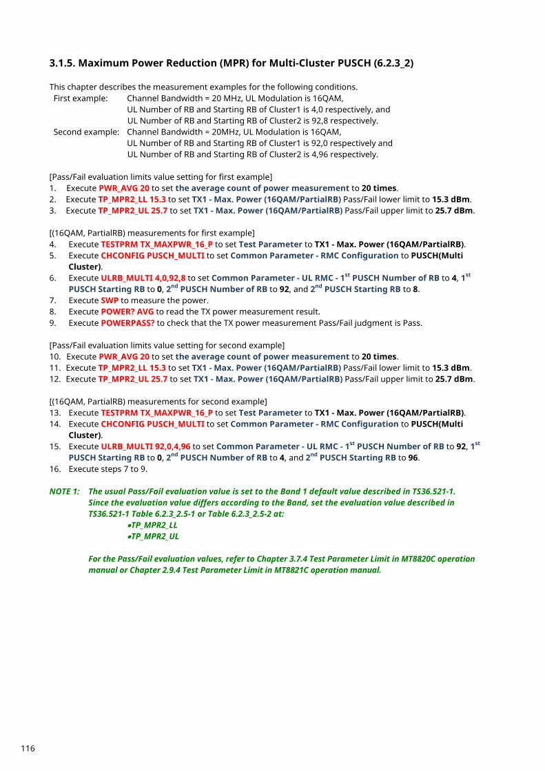
Maximum Power Reduction (MPR) for Multi-Cluster PUSCH (6.2.3_2) 3.1.5. This chapter describes the measurement examples for the following conditions. First example: Channel Bandwidth = 20 MHz, UL Modulation is 16QAM,
UL Number of RB and Starting RB of Cluster1 is 4,0 respectively, and UL Number of RB and Starting RB of Cluster2 is 92,8 respectively.
Second example: Channel Bandwidth = 20MHz, UL Modulation is 16QAM, UL Number of RB and Starting RB of Cluster1 is 92,0 respectively and UL Number of RB and Starting RB of Cluster2 is 4,96 respectively.
[Pass/Fail evaluation limits value setting for first example] 1. Execute PWR_AVG 20 to set the average count of power measurement to 20 times. 2. Execute TP_MPR2_LL 15.3 to set TX1 - Max. Power (16QAM/PartialRB) Pass/Fail lower limit to 15.3 dBm. 3. Execute TP_MPR2_UL 25.7 to set TX1 - Max. Power (16QAM/PartialRB) Pass/Fail upper limit to 25.7 dBm. [(16QAM, PartialRB) measurements for first example] 4. Execute TESTPRM TX_MAXPWR_16_P to set Test Parameter to TX1 - Max. Power (16QAM/PartialRB). 5. Execute CHCONFIG PUSCH_MULTI to set Common Parameter - RMC Configuration to PUSCH(Multi
Cluster). 6. Execute ULRB_MULTI 4,0,92,8 to set Common Parameter - UL RMC - 1st PUSCH Number of RB to 4, 1st
PUSCH Starting RB to 0, 2nd PUSCH Number of RB to 92, and 2nd PUSCH Starting RB to 8. 7. Execute SWP to measure the power. 8. Execute POWER? AVG to read the TX power measurement result. 9. Execute POWERPASS? to check that the TX power measurement Pass/Fail judgment is Pass. [Pass/Fail evaluation limits value setting for second example] 10. Execute PWR_AVG 20 to set the average count of power measurement to 20 times. 11. Execute TP_MPR2_LL 15.3 to set TX1 - Max. Power (16QAM/PartialRB) Pass/Fail lower limit to 15.3 dBm. 12. Execute TP_MPR2_UL 25.7 to set TX1 - Max. Power (16QAM/PartialRB) Pass/Fail upper limit to 25.7 dBm. [(16QAM, PartialRB) measurements for second example] 13. Execute TESTPRM TX_MAXPWR_16_P to set Test Parameter to TX1 - Max. Power (16QAM/PartialRB). 14. Execute CHCONFIG PUSCH_MULTI to set Common Parameter - RMC Configuration to PUSCH(Multi
Cluster). 15. Execute ULRB_MULTI 92,0,4,96 to set Common Parameter - UL RMC - 1st PUSCH Number of RB to 92, 1st
PUSCH Starting RB to 0, 2nd PUSCH Number of RB to 4, and 2nd PUSCH Starting RB to 96. 16. Execute steps 7 to 9. NOTE 1: The usual Pass/Fail evaluation value is set to the Band 1 default value described in TS36.521-1. Since the evaluation value differs according to the Band, set the evaluation value described in TS36.521-1 Table 6.2.3_2.5-1 or Table 6.2.3_2.5-2 at:
•TP_MPR2_LL •TP_MPR2_UL
For the Pass/Fail evaluation values, refer to Chapter 3.7.4 Test Parameter Limit in MT8820C operation manual or Chapter 2.9.4 Test Parameter Limit in MT8821C operation manual.
116
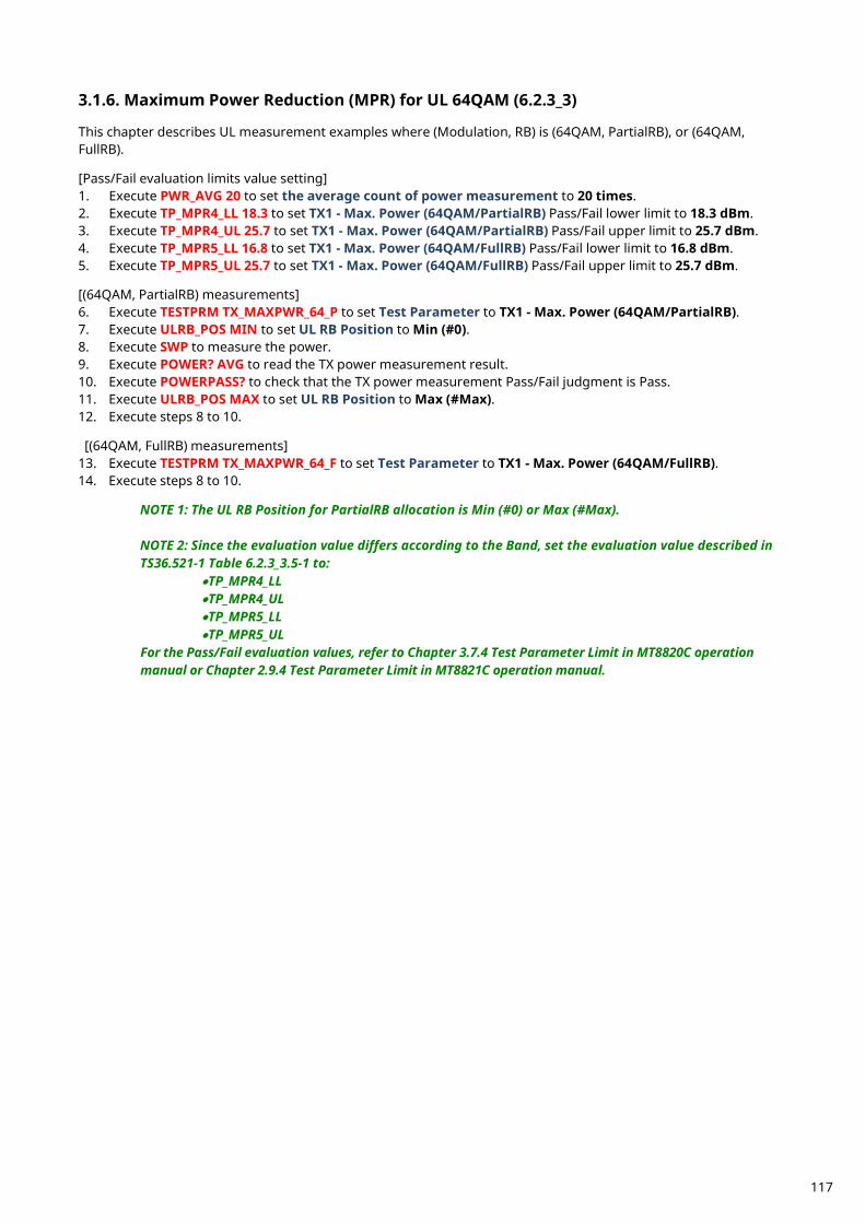
Maximum Power Reduction (MPR) for UL 64QAM (6.2.3_3) 3.1.6. This chapter describes UL measurement examples where (Modulation, RB) is (64QAM, PartialRB), or (64QAM, FullRB). [Pass/Fail evaluation limits value setting] 1. Execute PWR_AVG 20 to set the average count of power measurement to 20 times. 2. Execute TP_MPR4_LL 18.3 to set TX1 - Max. Power (64QAM/PartialRB) Pass/Fail lower limit to 18.3 dBm. 3. Execute TP_MPR4_UL 25.7 to set TX1 - Max. Power (64QAM/PartialRB) Pass/Fail upper limit to 25.7 dBm. 4. Execute TP_MPR5_LL 16.8 to set TX1 - Max. Power (64QAM/FullRB) Pass/Fail lower limit to 16.8 dBm. 5. Execute TP_MPR5_UL 25.7 to set TX1 - Max. Power (64QAM/FullRB) Pass/Fail upper limit to 25.7 dBm. [(64QAM, PartialRB) measurements] 6. Execute TESTPRM TX_MAXPWR_64_P to set Test Parameter to TX1 - Max. Power (64QAM/PartialRB). 7. Execute ULRB_POS MIN to set UL RB Position to Min (#0). 8. Execute SWP to measure the power. 9. Execute POWER? AVG to read the TX power measurement result. 10. Execute POWERPASS? to check that the TX power measurement Pass/Fail judgment is Pass. 11. Execute ULRB_POS MAX to set UL RB Position to Max (#Max). 12. Execute steps 8 to 10. [(64QAM, FullRB) measurements] 13. Execute TESTPRM TX_MAXPWR_64_F to set Test Parameter to TX1 - Max. Power (64QAM/FullRB). 14. Execute steps 8 to 10. NOTE 1: The UL RB Position for PartialRB allocation is Min (#0) or Max (#Max).
NOTE 2: Since the evaluation value differs according to the Band, set the evaluation value described in TS36.521-1 Table 6.2.3_3.5-1 to:
•TP_MPR4_LL •TP_MPR4_UL •TP_MPR5_LL •TP_MPR5_UL
For the Pass/Fail evaluation values, refer to Chapter 3.7.4 Test Parameter Limit in MT8820C operation manual or Chapter 2.9.4 Test Parameter Limit in MT8821C operation manual.
117
Maximum Power Reduction (MPR) for Multi-Cluster PUSCH with UL 64QAM (6.2.3_4) 3.1.7. This chapter describes the measurement examples for the following conditions. First example: Channel Bandwidth = 20 MHz, UL Modulation is 64QAM,
UL Number of RB and Starting RB of Cluster1 is 4,0 respectively, and UL Number of RB and Starting RB of Cluster2 is 92,8 respectively.
Second example: Channel Bandwidth = 20MHz, UL Modulation is 64QAM, UL Number of RB and Starting RB of Cluster1 is 92,0 respectively and UL Number of RB and Starting RB of Cluster2 is 4,96 respectively.
[Pass/Fail evaluation limits value setting for the first example] 1. Execute PWR_AVG 20 to set the average count of power measurement to 20 times. 2. Execute TP_MPR4_LL 15.3 to set TX1 - Max. Power (64QAM/PartialRB) Pass/Fail lower limit to 15.3 dBm. 3. Execute TP_MPR4_UL 25.7 to set TX1 - Max. Power (64QAM/PartialRB) Pass/Fail upper limit to 25.7 dBm. [Measurements for the first example] 4. Execute TESTPRM TX_MAXPWR_64_P to set Test Parameter to TX1 - Max. Power (64QAM/PartialRB). 5. Execute CHCONFIG PUSCH_MULTI to set Common Parameter - RMC Configuration to PUSCH(Multi
Cluster). 6. Execute ULRB_MULTI 4,0,92,8 to set Common Parameter - UL RMC - 1st PUSCH Number of RB to 4, 1st
PUSCH Starting RB to 0, 2nd PUSCH Number of RB to 92, and 2nd PUSCH Starting RB to 8. 7. Execute SWP to measure the power. 8. Execute POWER? AVG to read the TX power measurement result. 9. Execute POWERPASS? to check that the TX power measurement Pass/Fail judgment is Pass. [Pass/Fail evaluation limits value setting for the second example] 10. Execute PWR_AVG 20 to set the average count of power measurement to 20 times. 11. Execute TP_MPR4_LL 15.3 to set TX1 - Max. Power (64QAM/PartialRB) Pass/Fail lower limit to 15.3 dBm. 12. Execute TP_MPR4_UL 25.7 to set TX1 - Max. Power (64QAM/PartialRB) Pass/Fail upper limit to 25.7 dBm. [Measurements for the second example] 13. Execute TESTPRM TX_MAXPWR_64_P to set Test Parameter to TX1 - Max. Power (64QAM/PartialRB). 14. Execute CHCONFIG PUSCH_MULTI to set Common Parameter - RMC Configuration to PUSCH(Multi
Cluster). 15. Execute ULRB_MULTI 92,0,4,96 to set Common Parameter - UL RMC - 1st PUSCH Number of RB to 92, 1st
PUSCH Starting RB to 0, 2nd PUSCH Number of RB to 4, and 2nd PUSCH Starting RB to 96. 16. Execute steps 7 to 9. NOTE 1: Since the evaluation value differs according to the Band, set the evaluation value described in TS36.521-1 Table 6.2.3_4.5-1 to:
•TP_MPR4_LL •TP_MPR4_UL
For the Pass/Fail evaluation values, refer to Chapter 3.7.4 Test Parameter Limit in MT8820C operation manual or Chapter 2.9.4 Test Parameter Limit in MT8821C operation manual.
118

Configured UE transmitted Output Power (6.2.5) 3.1.8. This chapter describes a UL measurement example where (Modulation, RB) is (QPSK, PartialRB). [Pass/Fail evaluation limits value setting]
1. Execute PWR_AVG 20 to set the average count of Power measurement to 20 times. 2. Execute TP_CONFPWR1_TOL 7.7 to set TX2 - Configured UE transmitted Output Power (Test Point 1)
Pass/Fail Judgment. 3. Execute TP_CONFPWR2_TOL 6.7 to set TX2 - Configured UE transmitted Output Power (Test Point 2)
Pass/Fail Judgment. 4. Execute TP_CONFPWR3_TOL 5.7 to set TX2 - Configured UE transmitted Output Power (Test Point 3)
Pass/Fail Judgment. [Measurements]
5. Execute TESTPRM TX_CONF_PWR1 to set Test Parameter to TX2 - Configured Power (Test Point 1). 6. Execute SWP to measure power. 7. Execute POWER? AVG to read the TX Power measurement result. 8. Execute POWERPASS? to check that the TX Power measurement Pass/Fail judgment is Pass. 9. Execute TESTPRM TX_CONF_PWR2 to set Test Parameter to TX2 - Configured Power (Test Point 2).
10. Execute steps 6 to 8. 11. Execute TESTPRM TX_CONF_PWR3 to set Test Parameter to TX2 - Configured Power (Test Point 3). 12. Execute steps 6 to 8. NOTE 1: The UL RB Position of PartialRB allocation is Min (#0). NOTE 2: The Pass/Fail evaluation value is initialized as described in TS36.521-1 Table 6.2.5.5-1 and used when the Carrier Frequency is 3 GHz or less. When the Carrier Frequency exceeds 3 GHz, set
•TP_CONFPWR1_TOL 8.0 •TP_CONFPWR2_TOL 7.0 •TP_CONFPWR3_TOL 6.0 as described in TS36.521-1 Table 6.2.5.5-1.
For the Pass/Fail evaluation values, refer to Chapter 3.7.4 Test Parameter Limit in MT8820C operation manual or Chapter 2.9.4 Test Parameter Limit in MT8821C operation manual.
Figure 3.1.8-1 Example of Measurement Result when Test Parameter is TX2 - Configured Power (Test Point 1)
(MT8820C)
Figure 3.1.8-2 Example of Measurement Result when Test Parameter is TX2 - Configured Power (Test Point 1)
(MT8821C)
119
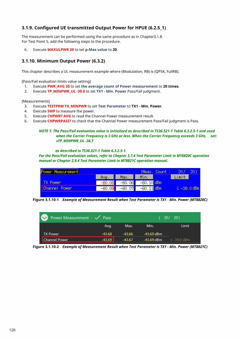
Configured UE transmitted Output Power for HPUE (6.2.5_1) 3.1.9. The measurement can be performed using the same procedure as in Chapter3.1.8. For Test Point 5, add the following steps to the procedure.
6. Execute MAXULPWR 20 to set p-Max value to 20.
Minimum Output Power (6.3.2) 3.1.10. This chapter describes a UL measurement example where (Modulation, RB) is (QPSK, FullRB). [Pass/Fail evaluation limits value setting]
1. Execute PWR_AVG 20 to set the average count of Power measurement to 20 times. 2. Execute TP_MINPWR_UL -39.0 to set TX1 - Min. Power Pass/Fail judgment.
[Measurements]
3. Execute TESTPRM TX_MINPWR to set Test Parameter to TX1 - Min. Power. 4. Execute SWP to measure the power. 5. Execute CHPWR? AVG to read the Channel Power measurement result. 6. Execute CHPWRPASS? to check that the Channel Power measurement Pass/Fail judgment is Pass.
NOTE 1: The Pass/Fail evaluation value is initialized as described in TS36.521-1 Table 6.3.2.5-1 and used when the Carrier Frequency is 3 GHz or less. When the Carrier Frequency exceeds 3 GHz, set:
•TP_MINPWR_UL -38.7 as described in TS36.521-1 Table 6.3.2.5-1.
For the Pass/Fail evaluation values, refer to Chapter 3.7.4 Test Parameter Limit in MT8820C operation manual or Chapter 2.9.4 Test Parameter Limit in MT8821C operation manual.
Figure 3.1.10-1 Example of Measurement Result when Test Parameter is TX1 - Min. Power (MT8820C)
Figure 3.1.10-2 Example of Measurement Result when Test Parameter is TX1 - Min. Power (MT8821C)
120
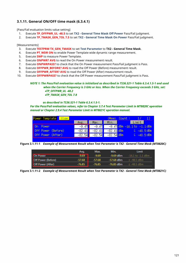
General ON/OFF time mask (6.3.4.1) 3.1.11. [Pass/Fail evaluation limits value setting]
1. Execute TP_OFFPWR_UL -48.5 to set TX2 - General Time Mask Off Power Pass/Fail judgment. 2. Execute TP_TMASK_GEN_TOL 7.5 to set TX2 - General Time Mask On Power Pass/Fail judgment.
[Measurements]
3. Execute TESTPRM TX_GEN_TMASK to set Test Parameter to TX2 - General Time Mask. 4. Execute PT_WDR ON to enable Power Template wide dynamic range measurement. 5. Execute SWP to measure Power Template. 6. Execute ONPWR? AVG to read the On Power measurement result. 7. Execute ONPWRPASS? to check that the On Power measurement Pass/Fail judgment is Pass. 8. Execute OFFPWR_BEFORE? AVG to read the Off Power (Before) measurement result. 9. Execute OFFPWR_AFTER? AVG to read the Off Power (After) measurement result.
10. Execute OFFPWRPASS? to check that the Off Power measurement Pass/Fail judgment is Pass.
NOTE 1: The Pass/Fail evaluation value is initialized as described in TS36.521-1 Table 6.3.4.1.5-1 and used when the Carrier Frequency is 3 GHz or less. When the Carrier Frequency exceeds 3 GHz, set:
•TP_OFFPWR_UL -48.2 •TP_TMASK_GEN_TOL 7.8
as described in TS36.521-1 Table 6.3.4.1.5-1.
For the Pass/Fail evaluation values, refer to Chapter 3.7.4 Test Parameter Limit in MT8820C operation manual or Chapter 2.9.4 Test Parameter Limit in MT8821C operation manual.
Figure 3.1.11-1 Example of Measurement Result when Test Parameter is TX2 - General Time Mask (MT8820C)
Figure 3.1.11-2 Example of Measurement Result when Test Parameter is TX2 - General Time Mask (MT8821C)
121
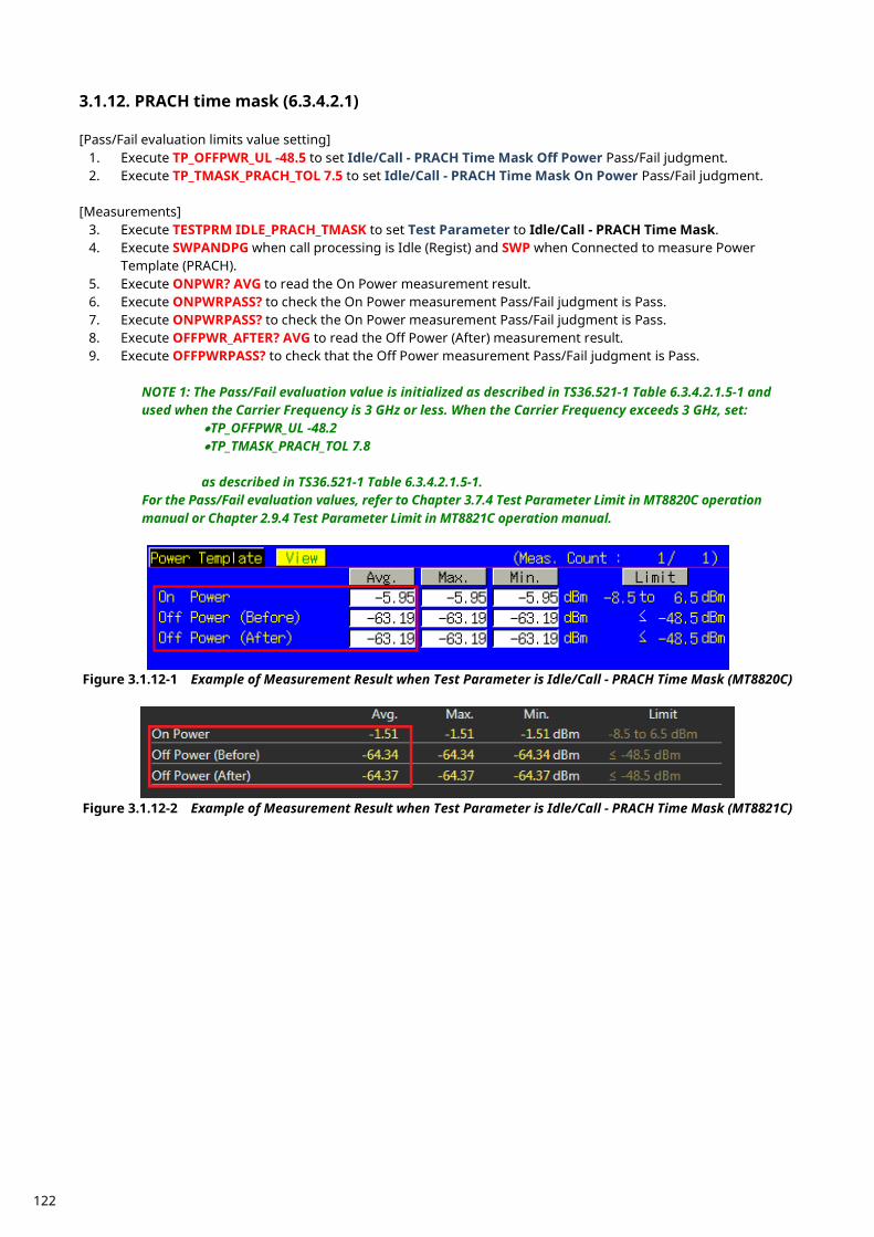
PRACH time mask (6.3.4.2.1) 3.1.12. [Pass/Fail evaluation limits value setting]
1. Execute TP_OFFPWR_UL -48.5 to set Idle/Call - PRACH Time Mask Off Power Pass/Fail judgment. 2. Execute TP_TMASK_PRACH_TOL 7.5 to set Idle/Call - PRACH Time Mask On Power Pass/Fail judgment.
[Measurements]
3. Execute TESTPRM IDLE_PRACH_TMASK to set Test Parameter to Idle/Call - PRACH Time Mask. 4. Execute SWPANDPG when call processing is Idle (Regist) and SWP when Connected to measure Power
Template (PRACH). 5. Execute ONPWR? AVG to read the On Power measurement result. 6. Execute ONPWRPASS? to check the On Power measurement Pass/Fail judgment is Pass. 7. Execute ONPWRPASS? to check the On Power measurement Pass/Fail judgment is Pass. 8. Execute OFFPWR_AFTER? AVG to read the Off Power (After) measurement result. 9. Execute OFFPWRPASS? to check that the Off Power measurement Pass/Fail judgment is Pass.
NOTE 1: The Pass/Fail evaluation value is initialized as described in TS36.521-1 Table 6.3.4.2.1.5-1 and used when the Carrier Frequency is 3 GHz or less. When the Carrier Frequency exceeds 3 GHz, set:
•TP_OFFPWR_UL -48.2 •TP_TMASK_PRACH_TOL 7.8 as described in TS36.521-1 Table 6.3.4.2.1.5-1.
For the Pass/Fail evaluation values, refer to Chapter 3.7.4 Test Parameter Limit in MT8820C operation manual or Chapter 2.9.4 Test Parameter Limit in MT8821C operation manual.
Figure 3.1.12-1 Example of Measurement Result when Test Parameter is Idle/Call - PRACH Time Mask (MT8820C)
Figure 3.1.12-2 Example of Measurement Result when Test Parameter is Idle/Call - PRACH Time Mask (MT8821C)
122
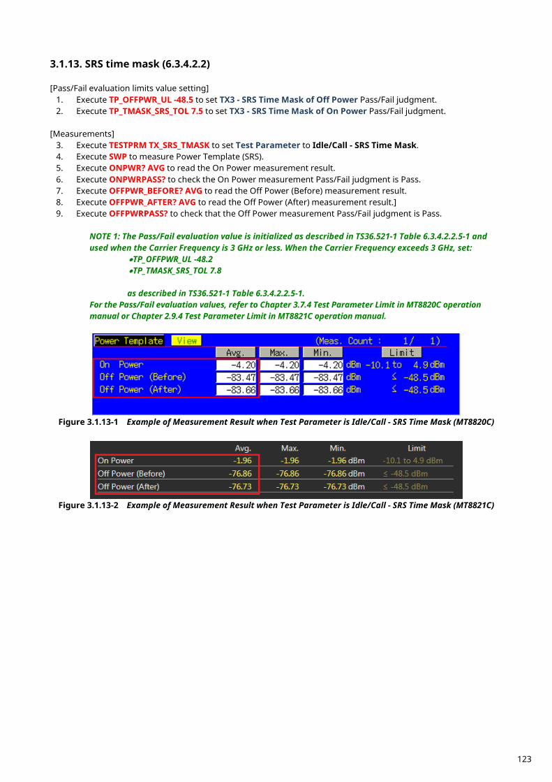
SRS time mask (6.3.4.2.2) 3.1.13. [Pass/Fail evaluation limits value setting]
1. Execute TP_OFFPWR_UL -48.5 to set TX3 - SRS Time Mask of Off Power Pass/Fail judgment. 2. Execute TP_TMASK_SRS_TOL 7.5 to set TX3 - SRS Time Mask of On Power Pass/Fail judgment.
[Measurements]
3. Execute TESTPRM TX_SRS_TMASK to set Test Parameter to Idle/Call - SRS Time Mask. 4. Execute SWP to measure Power Template (SRS). 5. Execute ONPWR? AVG to read the On Power measurement result. 6. Execute ONPWRPASS? to check the On Power measurement Pass/Fail judgment is Pass. 7. Execute OFFPWR_BEFORE? AVG to read the Off Power (Before) measurement result. 8. Execute OFFPWR_AFTER? AVG to read the Off Power (After) measurement result.] 9. Execute OFFPWRPASS? to check that the Off Power measurement Pass/Fail judgment is Pass.
NOTE 1: The Pass/Fail evaluation value is initialized as described in TS36.521-1 Table 6.3.4.2.2.5-1 and used when the Carrier Frequency is 3 GHz or less. When the Carrier Frequency exceeds 3 GHz, set:
•TP_OFFPWR_UL -48.2 •TP_TMASK_SRS_TOL 7.8 as described in TS36.521-1 Table 6.3.4.2.2.5-1.
For the Pass/Fail evaluation values, refer to Chapter 3.7.4 Test Parameter Limit in MT8820C operation manual or Chapter 2.9.4 Test Parameter Limit in MT8821C operation manual.
Figure 3.1.13-1 Example of Measurement Result when Test Parameter is Idle/Call - SRS Time Mask (MT8820C)
Figure 3.1.13-2 Example of Measurement Result when Test Parameter is Idle/Call - SRS Time Mask (MT8821C)
123
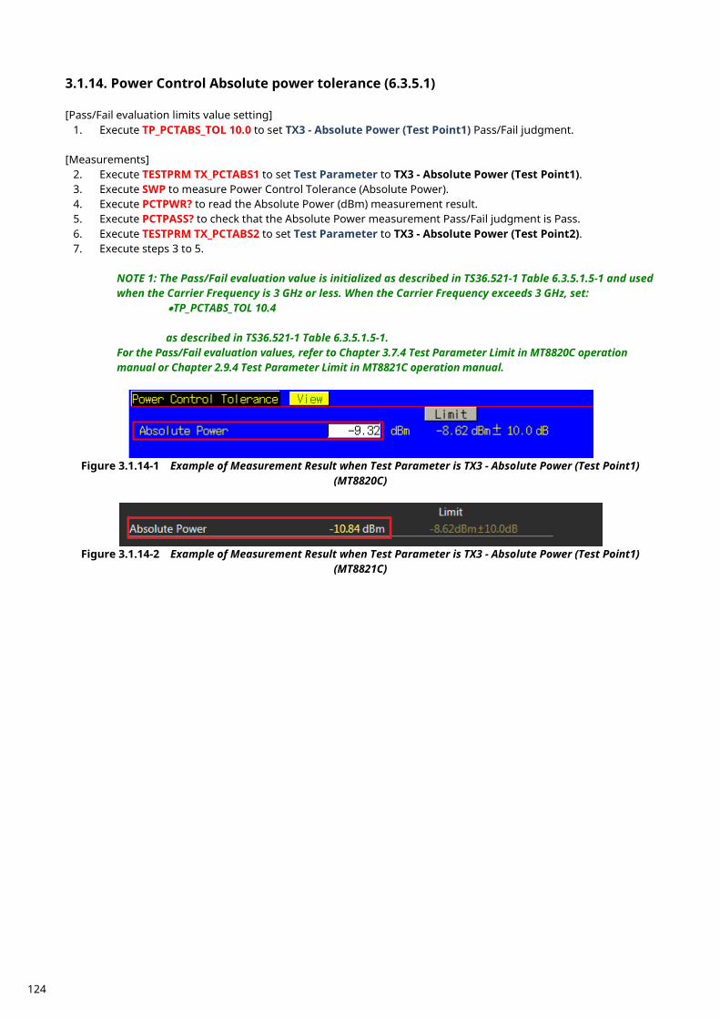
Power Control Absolute power tolerance (6.3.5.1) 3.1.14. [Pass/Fail evaluation limits value setting]
1. Execute TP_PCTABS_TOL 10.0 to set TX3 - Absolute Power (Test Point1) Pass/Fail judgment. [Measurements]
2. Execute TESTPRM TX_PCTABS1 to set Test Parameter to TX3 - Absolute Power (Test Point1). 3. Execute SWP to measure Power Control Tolerance (Absolute Power). 4. Execute PCTPWR? to read the Absolute Power (dBm) measurement result. 5. Execute PCTPASS? to check that the Absolute Power measurement Pass/Fail judgment is Pass. 6. Execute TESTPRM TX_PCTABS2 to set Test Parameter to TX3 - Absolute Power (Test Point2). 7. Execute steps 3 to 5.
NOTE 1: The Pass/Fail evaluation value is initialized as described in TS36.521-1 Table 6.3.5.1.5-1 and used when the Carrier Frequency is 3 GHz or less. When the Carrier Frequency exceeds 3 GHz, set:
•TP_PCTABS_TOL 10.4 as described in TS36.521-1 Table 6.3.5.1.5-1.
For the Pass/Fail evaluation values, refer to Chapter 3.7.4 Test Parameter Limit in MT8820C operation manual or Chapter 2.9.4 Test Parameter Limit in MT8821C operation manual.
Figure 3.1.14-1 Example of Measurement Result when Test Parameter is TX3 - Absolute Power (Test Point1)
(MT8820C)
Figure 3.1.14-2 Example of Measurement Result when Test Parameter is TX3 - Absolute Power (Test Point1)
(MT8821C)
124
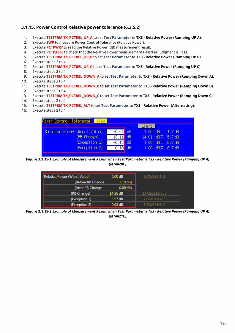
Power Control Relative power tolerance (6.3.5.2) 3.1.15.
1. Execute TESTPRM TX_PCTREL_UP_A to set Test Parameter to TX3 - Relative Power (Ramping UP A). 2. Execute SWP to measure Power Control Tolerance (Relative Power). 3. Execute PCTPWR? to read the Relative Power (dB) measurement result. 4. Execute PCTPASS? to check that the Relative Power measurement Pass/Fail judgment is Pass. 5. Execute TESTPRM TX_PCTREL_UP_B to set Test Parameter to TX3 - Relative Power (Ramping UP B). 6. Execute steps 2 to 4. 7. Execute TESTPRM TX_PCTREL_UP_C to set Test Parameter to TX3 - Relative Power (Ramping UP C). 8. Execute steps 2 to 4. 9. Execute TESTPRM TX_PCTREL_DOWN_A to set Test Parameter to TX3 - Relative Power (Ramping Down A).
10. Execute steps 2 to 4. 11. Execute TESTPRM TX_PCTREL_DOWN_B to set Test Parameter to TX3 - Relative Power (Ramping Down B). 12. Execute steps 2 to 4. 13. Execute TESTPRM TX_PCTREL_DOWN_C to set Test Parameter to TX3 - Relative Power (Ramping Down C). 14. Execute steps 2 to 4. 15. Execute TESTPRM TX_PCTREL_ALT to set Test Parameter to TX3 - Relative Power (Alternating). 16. Execute steps 2 to 4.
Figure 3.1.15-1 Example of Measurement Result when Test Parameter is TX3 - Relative Power (Ramping UP A)
(MT8820C)
Figure 3.1.15-2 Example of Measurement Result when Test Parameter is TX3 - Relative Power (Ramping UP A)
(MT8821C)
125
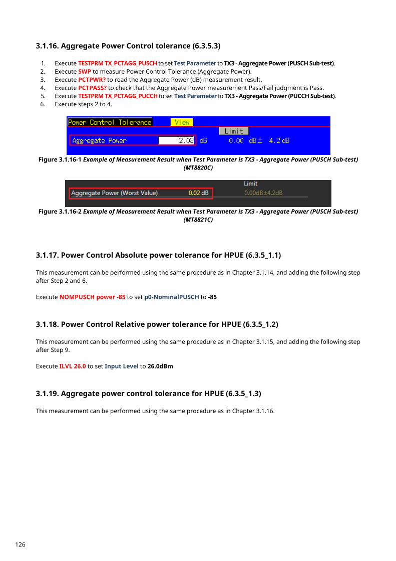
Aggregate Power Control tolerance (6.3.5.3) 3.1.16.
1. Execute TESTPRM TX_PCTAGG_PUSCH to set Test Parameter to TX3 - Aggregate Power (PUSCH Sub-test). 2. Execute SWP to measure Power Control Tolerance (Aggregate Power). 3. Execute PCTPWR? to read the Aggregate Power (dB) measurement result. 4. Execute PCTPASS? to check that the Aggregate Power measurement Pass/Fail judgment is Pass. 5. Execute TESTPRM TX_PCTAGG_PUCCH to set Test Parameter to TX3 - Aggregate Power (PUCCH Sub-test). 6. Execute steps 2 to 4.
Figure 3.1.16-1 Example of Measurement Result when Test Parameter is TX3 - Aggregate Power (PUSCH Sub-test)
(MT8820C)
Figure 3.1.16-2 Example of Measurement Result when Test Parameter is TX3 - Aggregate Power (PUSCH Sub-test)
(MT8821C)
Power Control Absolute power tolerance for HPUE (6.3.5_1.1) 3.1.17. This measurement can be performed using the same procedure as in Chapter 3.1.14, and adding the following step after Step 2 and 6. Execute NOMPUSCH power -85 to set p0-NominalPUSCH to -85
Power Control Relative power tolerance for HPUE (6.3.5_1.2) 3.1.18. This measurement can be performed using the same procedure as in Chapter 3.1.15, and adding the following step after Step 9. Execute ILVL 26.0 to set Input Level to 26.0dBm
Aggregate power control tolerance for HPUE (6.3.5_1.3) 3.1.19. This measurement can be performed using the same procedure as in Chapter 3.1.16.
126
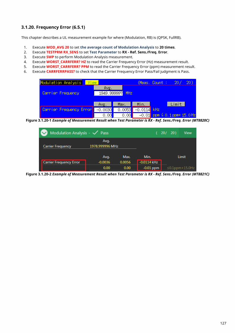
Frequency Error (6.5.1) 3.1.20. This chapter describes a UL measurement example for where (Modulation, RB) is (QPSK, FullRB).
1. Execute MOD_AVG 20 to set the average count of Modulation Analysis to 20 times. 2. Execute TESTPRM RX_SENS to set Test Parameter to RX - Ref. Sens./Freq. Error. 3. Execute SWP to perform Modulation Analysis measurement. 4. Execute WORST_CARRFERR? HZ to read the Carrier Frequency Error (Hz) measurement result. 5. Execute WORST_CARRFERR? PPM to read the Carrier Frequency Error (ppm) measurement result. 6. Execute CARRFERRPASS? to check that the Carrier Frequency Error Pass/Fail judgment is Pass.
Figure 3.1.20-1 Example of Measurement Result when Test Parameter is RX - Ref. Sens./Freq. Error (MT8820C)
Figure 3.1.20-2 Example of Measurement Result when Test Parameter is RX - Ref. Sens./Freq. Error (MT8821C)
127
Error Vector Magnitude (EVM) - PUSCH (6.5.2.1) 3.1.21. This chapter describes UL measurement examples where (Modulation, RB) is (QPSK, PartialRB), (QPSK, FullRB), (16QAM, PartialRB) or (16QAM, FullRB).
1. Execute MOD_AVG 20 to set the average count of Modulation Analysis to 20 times. [(QPSK, PartialRB) measurements]
2. Execute TESTPRM TX_MAXPWR_Q_P to set Test Parameter to TX1 - Max. Power (QPSK/PartialRB). 3. Execute ULRB_POS MIN to set UL RB Position to Min (#0). 4. Execute SWP to measure Modulation Analysis. 5. Execute EVM? AVG to read the EVM measurement result. 6. Execute EVMPASS? to check that the EVM Pass/Fail judgment is Pass. 7. Execute RSEVM? AVG to read the Reference Signal EVM measurement result. 8. Execute RSEVMPASS? to check that the Reference Signal EVM Pass/Fail judgment is Pass. 9. Execute ULRB_POS MAX to set UL RB Position to Max (#max).
10. Execute steps 4 to 8. 11. Execute TESTPRM TX_M40DBM_Q_P to set Test Parameter to TX1 - EVM/IBE/LEAK @ -40 dBm
(QPSK/PartialRB) 12. Execute steps 3 to 10. [(QPSK, FullRB) measurements] 13. Execute TESTPRM TX_MAXPWR_Q_F to set Test Parameter to TX1 - Max. Power (QPSK/FullRB). 14. Execute steps 4 to 8. 15. Execute TESTPRM TX_M40DBM_Q_F to set Test Parameter to TX1 - EVM @ -40 dBm (QPSK/Full RB). 16. Execute steps 4 to 8. [(16QAM, PartialRB) measurements] 17. Execute TESTPRM TX_MAXPWR_16_P to set Test Parameter to TX1 - Max. Power (16QAM/PartialRB). 18. Execute steps 3 to 10. 19. Execute TESTPRM TX_M40DBM_16_P to set Test Parameter to TX1 - EVM @ -40 dBm (16QAM/Partial RB). 20. Execute steps 3 to 10. [(16QAM, FullRB) measurements] 21. Execute TESTPRM TX_MAXPWR_16_F to set Test Parameter to TX1 - Max. Power (16QAM/FullRB). 22. Execute steps 4 to 8. 23. Execute TESTPRM TX_M40DBM_16_F to set Test Parameter to TX1 - EVM @ -40 dBm (16QAM/Full RB). 24. Execute steps 4 to 8. NOTE 1: The UL RB Position for PartialRB allocation is Min (#0) or Max (#max).
128
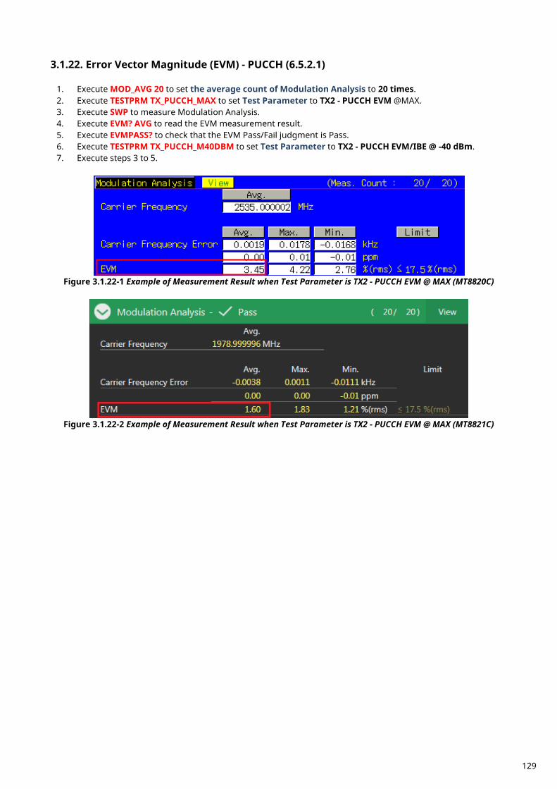
Error Vector Magnitude (EVM) - PUCCH (6.5.2.1) 3.1.22.
1. Execute MOD_AVG 20 to set the average count of Modulation Analysis to 20 times. 2. Execute TESTPRM TX_PUCCH_MAX to set Test Parameter to TX2 - PUCCH EVM @MAX. 3. Execute SWP to measure Modulation Analysis. 4. Execute EVM? AVG to read the EVM measurement result. 5. Execute EVMPASS? to check that the EVM Pass/Fail judgment is Pass. 6. Execute TESTPRM TX_PUCCH_M40DBM to set Test Parameter to TX2 - PUCCH EVM/IBE @ -40 dBm. 7. Execute steps 3 to 5.
Figure 3.1.22-1 Example of Measurement Result when Test Parameter is TX2 - PUCCH EVM @ MAX (MT8820C)
Figure 3.1.22-2 Example of Measurement Result when Test Parameter is TX2 - PUCCH EVM @ MAX (MT8821C)
129
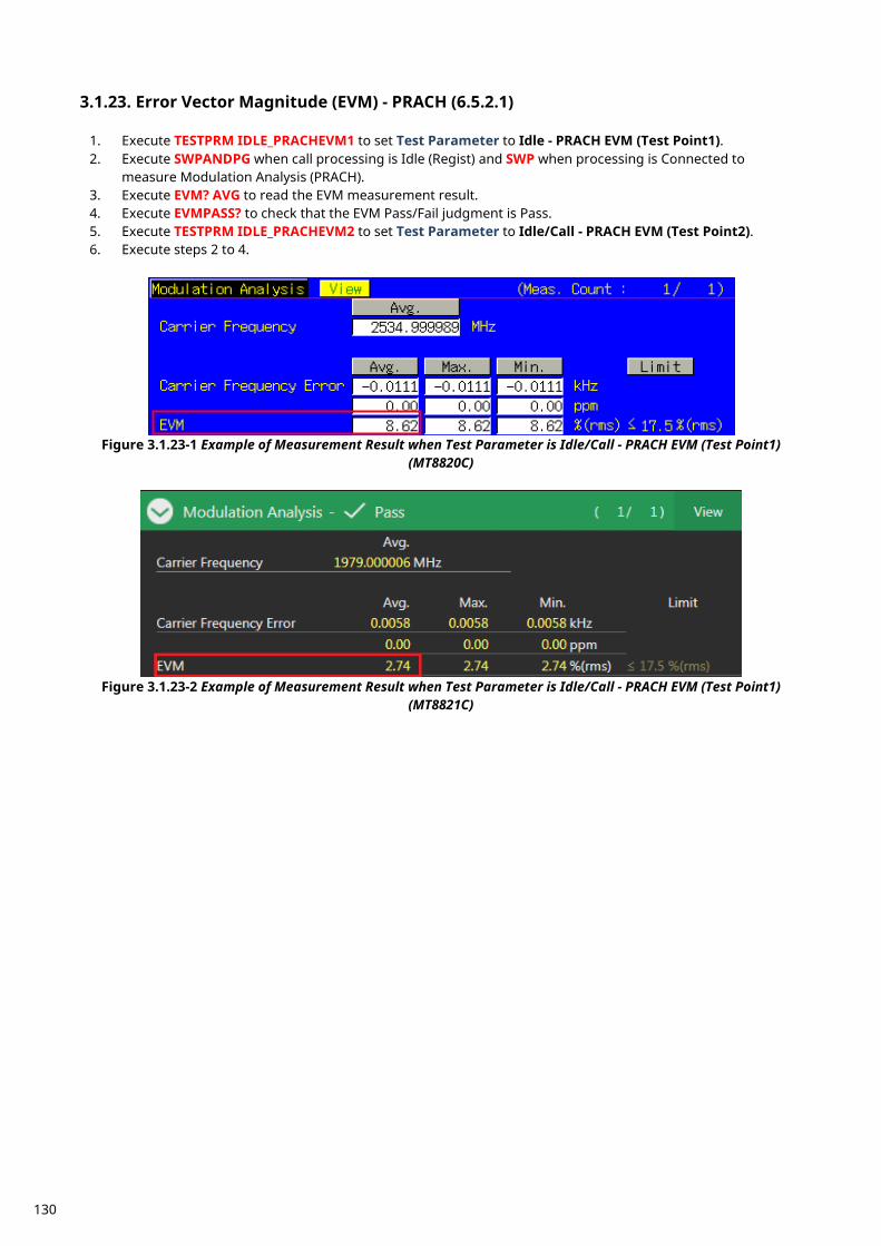
Error Vector Magnitude (EVM) - PRACH (6.5.2.1) 3.1.23.
1. Execute TESTPRM IDLE_PRACHEVM1 to set Test Parameter to Idle - PRACH EVM (Test Point1). 2. Execute SWPANDPG when call processing is Idle (Regist) and SWP when processing is Connected to
measure Modulation Analysis (PRACH). 3. Execute EVM? AVG to read the EVM measurement result. 4. Execute EVMPASS? to check that the EVM Pass/Fail judgment is Pass. 5. Execute TESTPRM IDLE_PRACHEVM2 to set Test Parameter to Idle/Call - PRACH EVM (Test Point2). 6. Execute steps 2 to 4.
Figure 3.1.23-1 Example of Measurement Result when Test Parameter is Idle/Call - PRACH EVM (Test Point1)
(MT8820C)
Figure 3.1.23-2 Example of Measurement Result when Test Parameter is Idle/Call - PRACH EVM (Test Point1)
(MT8821C)
130
Error Vector Magnitude (EVM) for UL 64QAM (6.5.2.1_1) 3.1.24. This chapter describes UL measurement examples where (Modulation, RB) is (64QAM, PartialRB) or (64QAM, FullRB).
1. Execute MOD_AVG 20 to set the average count of Modulation Analysis to 20 times. [(64QAM, PartialRB) measurements]
2. Execute TESTPRM TX_MAXPWR_64_P to set Test Parameter to TX1 - Max. Power (64QAM/PartialRB). 3. Execute ULRB_POS MIN to set UL RB Position to Min (#0). 4. Execute SWP to measure Modulation Analysis. 5. Execute EVM? AVG to read the EVM measurement result. 6. Execute EVMPASS? to check that the EVM Pass/Fail judgment is Pass. 7. Execute RSEVM? AVG to read the Reference Signal EVM measurement result. 8. Execute RSEVMPASS? to check that the Reference Signal EVM Pass/Fail judgment is Pass. 9. Execute ULRB_POS MAX to set UL RB Position to Max (#max).
10. Execute steps 4 to 8. 11. Execute TESTPRM TX_M40DBM_64_P to set Test Parameter to TX1 - EVM/IBE/LEAK @ -40 dBm
(64QAM/PartialRB) 12. Execute steps 3 to 10. [(64QAM, FullRB) measurements] 13. Execute TESTPRM TX_MAXPWR_64_F to set Test Parameter to TX1 - Max. Power (64QAM/FullRB). 14. Execute steps 4 to 8. 15. Execute TESTPRM TX_M40DBM_64_F to set Test Parameter to TX1 - EVM @ -40 dBm (64QAM/Full RB). 16. Execute steps 4 to 8. NOTE 1: The UL RB Position for PartialRB allocation is Min (#0) or Max (#max).
131
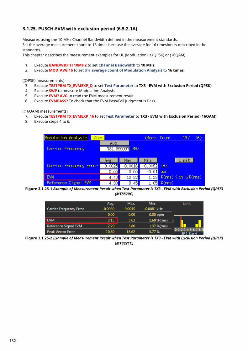
PUSCH-EVM with exclusion period (6.5.2.1A) 3.1.25. Measures using the 10 MHz Channel Bandwidth defined in the measurement standards. Set the average measurement count to 16 times because the average for 16 timeslots is described in the standards. This chapter describes the measurement examples for UL (Modulation) is (QPSK) or (16QAM).
1. Execute BANDWIDTH 10MHZ to set Channel Bandwidth to 10 MHz. 2. Execute MOD_AVG 16 to set the average count of Modulation Analysis to 16 times.
[(QPSK) measurements]
3. Execute TESTPRM TX_EVMEXP_Q to set Test Parameter to TX3 - EVM with Exclusion Period (QPSK). 4. Execute SWP to measure Modulation Analysis. 5. Execute EVM? AVG to read the EVM measurement result. 6. Execute EVMPASS? To check that the EVM Pass/Fail judgment is Pass.
[(16QAM) measurements]
7. Execute TESTPRM TX_EVMEXP_16 to set Test Parameter to TX3 - EVM with Exclusion Period (16QAM). 8. Execute steps 4 to 6.
Figure 3.1.25-1 Example of Measurement Result when Test Parameter is TX3 - EVM with Exclusion Period (QPSK)
(MT8820C)
Figure 3.1.25-2 Example of Measurement Result when Test Parameter is TX3 - EVM with Exclusion Period (QPSK)
(MT8821C)
132
Carrier leakage (6.5.2.2) 3.1.26. This chapter describes a UL measurement example where (Modulation, RB) is (QPSK, PartialRB).
1. Execute MOD_AVG 20 to set the average count of Modulation Analysis to 20 times. 2. Execute TESTPRM TX_0DBM to set Test Parameter to TX1 - IBE/LEAK @ 0 dBm. 3. Execute ULRB_POS MIN to set UL RB Position to Min(#0). 4. Execute SWP to measure Modulation Analysis. 5. Execute CARRLEAK? MAX to read the Carrier Leakage measurement result. 6. Execute CARRLEAKPASS? to check that the Carrier Leakage Pass/Fail judgment is Pass. 7. Execute ULRB_POS MAX to set UL RB Position to Max(#max) 8. Execute steps 4 to 6. 9. Execute TESTPRM TX_M30DBM to set Test Parameter to TX1 - IBE/LEAK @ -30 dBm.
10. Execute steps 3 to 8. 11. Execute TESTPRM TX_M40DBM_Q_P to set Test Parameter to TX1 - EVM/IBE/LEAK @ -40 dBm
(QPSK/PartialRB). 12. Execute steps 3 to 8. NOTE 1: The UL RB Position of PartialRB allocation is Min (#0) or Max (#max).
In-band emissions for non allocated RB - PUSCH (6.5.2.3) 3.1.27. This chapter describes a UL measurement example where (Modulation, RB) is (QPSK, PartialRB).
1. Execute MOD_AVG 20 to set the average count of Modulation Analysis to 20 times. 2. Execute TESTPRM TX_0DBM to set Test Parameter to TX1 - IBE/LEAK @ 0 dBm. 3. Execute ULRB_POS MIN to set UL RB Position to Min(#0). 4. Execute SWP to measure Modulation Analysis. 5. Execute INBANDE_GEN? MAX to read the In-band Emissions (General) measurement result. 6. Execute INBANDE_IMG? MAX to read the In-band Emissions (IQ Image) measurement result. 7. Execute INBANDE_LEAK? MAX to read the In-band Emissions (Carrier Leakage) measurement result. 8. Execute INBANDEPASS? to check that the In-band Emissions Pass/Fail judgment is Pass. 9. Execute ULRB_POS MAX to set UL RB Position to Max(#max).
10. Execute steps 4 to 8. 11. Execute TESTPRM TX_M30DBM to set Test Parameter to TX1 - IBE/LEAK @ -30 dBm. 12. Execute steps 3 to 10. 13. Execute TESTPRM TX_M40DBM_Q_P to set Test Parameter to TX1 - EVM/IBE/LEAK @ -40 dBm
(QPSK/PartialRB). 14. Execute steps 3 to 10. NOTE 1: The UL RB Position for PartialRB allocation is Min (#0) or Max (#max).
133
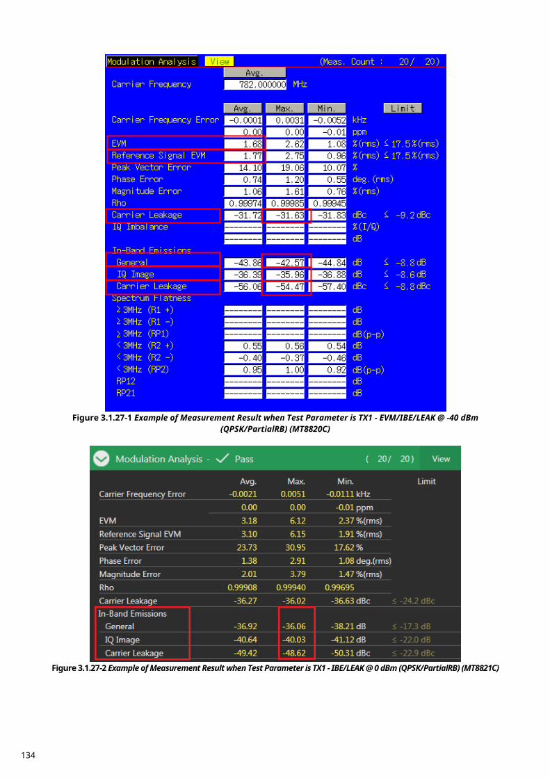
Figure 3.1.27-1 Example of Measurement Result when Test Parameter is TX1 - EVM/IBE/LEAK @ -40 dBm
(QPSK/PartialRB) (MT8820C)
Figure 3.1.27-2 Example of Measurement Result when Test Parameter is TX1 - IBE/LEAK @ 0 dBm (QPSK/PartialRB) (MT8821C)
134

In-band emissions for non allocated RB - PUCCH (6.5.2.3) 3.1.28.
1. Execute MOD_AVG 20 to set the average count of Modulation Analysis to 20 times. 2. Execute TESTPRM TX_PUCCH_0DBM to set Test Parameter to TX2 - PUCCH IBE @ 0 dBm. 3. Execute SWP to measure Modulation Analysis. 4. Execute INBANDE_GEN? MAX to read the In-band Emissions (General) measurement result. 5. Execute INBANDE_IMG? MAX to read the In-band Emissions (IQ Image) measurement result. 6. Execute INBANDE_LEAK? MAX to read the In-band Emissions (Carrier Leakage) measurement result. 7. Execute INBANDEPASS? to check that the In-band Emissions Pass/Fail judgment is Pass. 8. Execute TESTPRM TX_PUCCH_M30DBM to set Test Parameter to TX2 - PUCCH IBE @ -30 dBm. 9. Execute steps 3 to 7.
10. Execute TESTPRM TX_PUCCH_M40DBM to set Test Parameter to TX2 - PUCCH EVM/IBE @ -40 dBm. 11. Execute steps 3 to 7. NOTE 1: The UL RB Position for PartialRB allocation is Min (#0) or Max (#max).
Figure 3.1.28-1 Example of Measurement Result when Test Parameter is TX2 - PUCCH IBE @ 0 dBm (MT8820C)
135
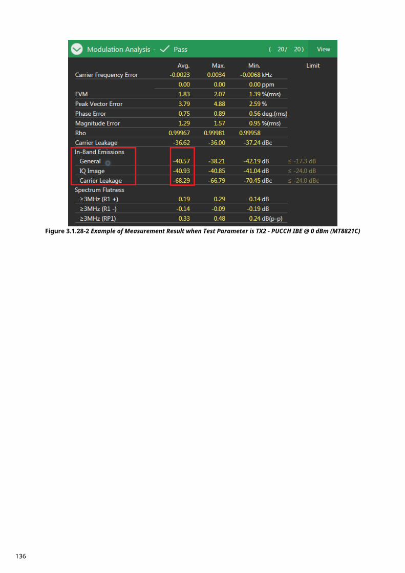
Figure 3.1.28-2 Example of Measurement Result when Test Parameter is TX2 - PUCCH IBE @ 0 dBm (MT8821C)
136
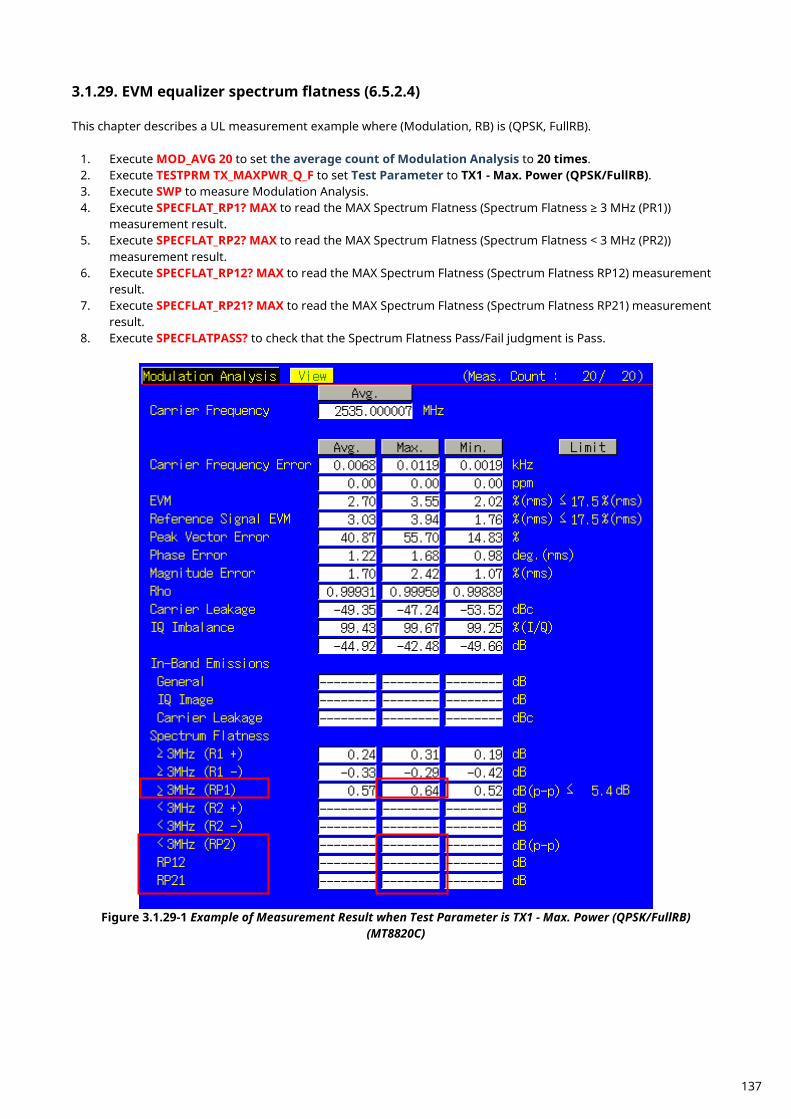
EVM equalizer spectrum flatness (6.5.2.4) 3.1.29. This chapter describes a UL measurement example where (Modulation, RB) is (QPSK, FullRB).
1. Execute MOD_AVG 20 to set the average count of Modulation Analysis to 20 times. 2. Execute TESTPRM TX_MAXPWR_Q_F to set Test Parameter to TX1 - Max. Power (QPSK/FullRB). 3. Execute SWP to measure Modulation Analysis. 4. Execute SPECFLAT_RP1? MAX to read the MAX Spectrum Flatness (Spectrum Flatness ≥ 3 MHz (PR1))
measurement result. 5. Execute SPECFLAT_RP2? MAX to read the MAX Spectrum Flatness (Spectrum Flatness < 3 MHz (PR2))
measurement result. 6. Execute SPECFLAT_RP12? MAX to read the MAX Spectrum Flatness (Spectrum Flatness RP12) measurement
result. 7. Execute SPECFLAT_RP21? MAX to read the MAX Spectrum Flatness (Spectrum Flatness RP21) measurement
result. 8. Execute SPECFLATPASS? to check that the Spectrum Flatness Pass/Fail judgment is Pass.
Figure 3.1.29-1 Example of Measurement Result when Test Parameter is TX1 - Max. Power (QPSK/FullRB)
(MT8820C)
137
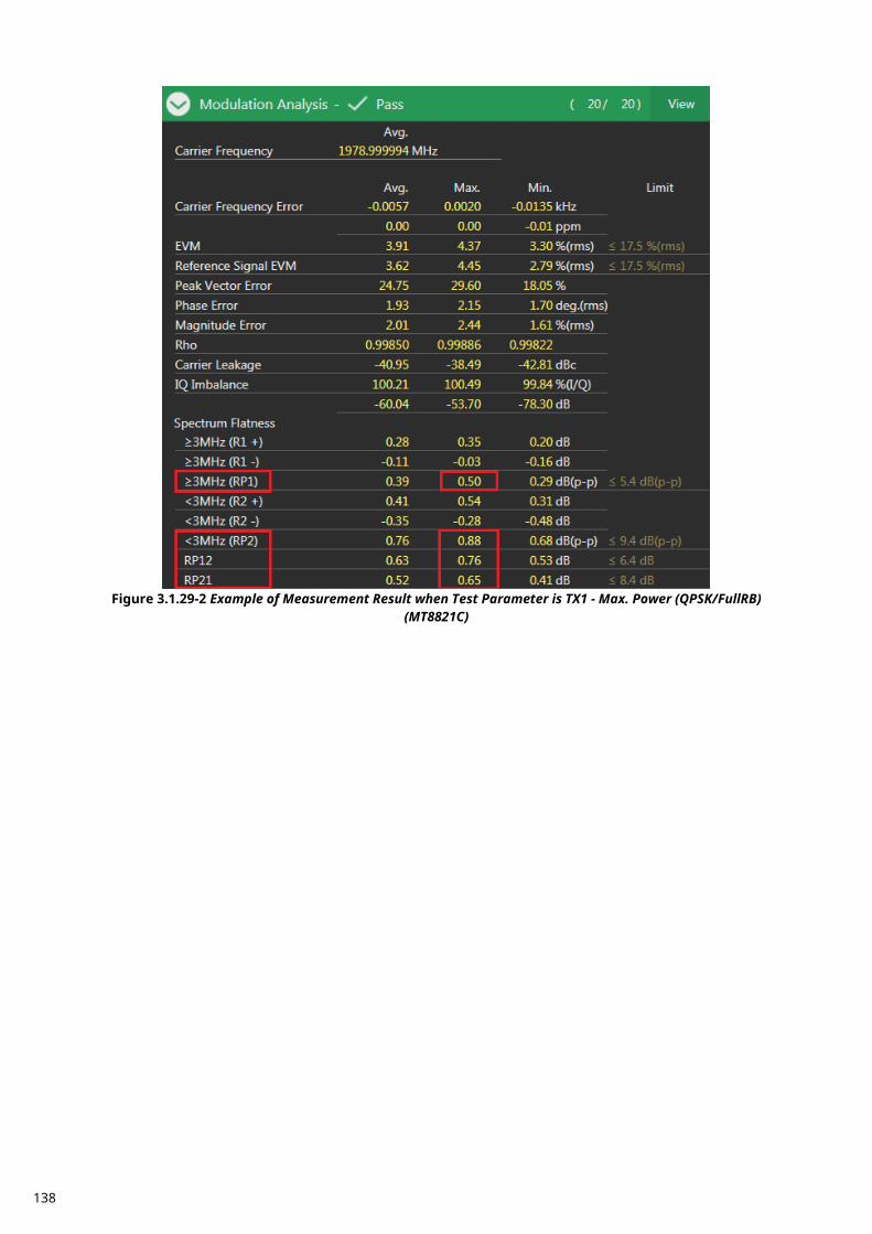
Figure 3.1.29-2 Example of Measurement Result when Test Parameter is TX1 - Max. Power (QPSK/FullRB)
(MT8821C)
138
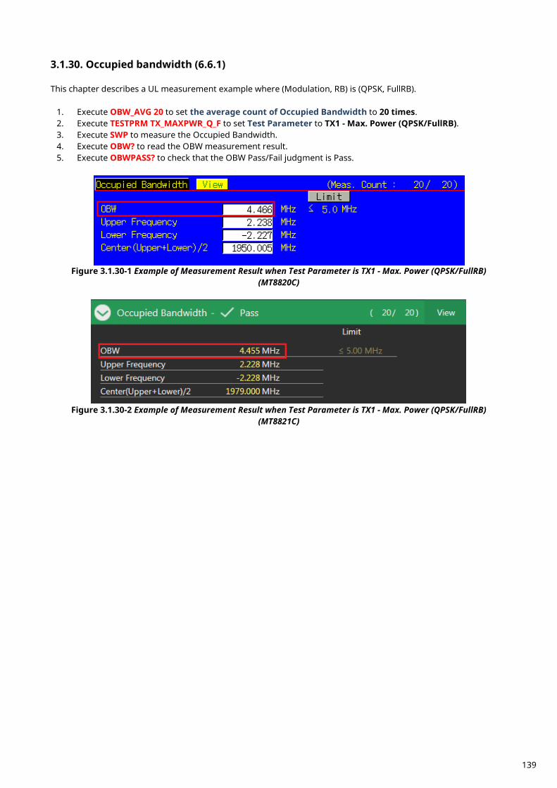
Occupied bandwidth (6.6.1) 3.1.30. This chapter describes a UL measurement example where (Modulation, RB) is (QPSK, FullRB).
1. Execute OBW_AVG 20 to set the average count of Occupied Bandwidth to 20 times. 2. Execute TESTPRM TX_MAXPWR_Q_F to set Test Parameter to TX1 - Max. Power (QPSK/FullRB). 3. Execute SWP to measure the Occupied Bandwidth. 4. Execute OBW? to read the OBW measurement result. 5. Execute OBWPASS? to check that the OBW Pass/Fail judgment is Pass.
Figure 3.1.30-1 Example of Measurement Result when Test Parameter is TX1 - Max. Power (QPSK/FullRB)
(MT8820C)
Figure 3.1.30-2 Example of Measurement Result when Test Parameter is TX1 - Max. Power (QPSK/FullRB)
(MT8821C)
139
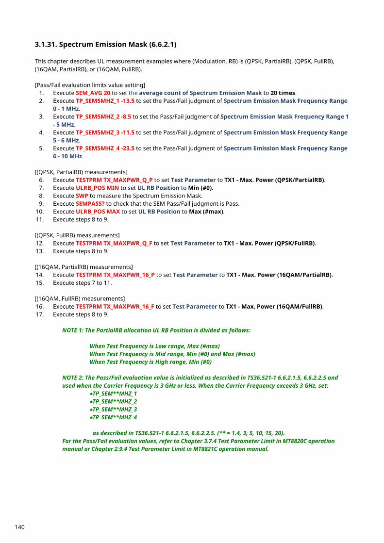
Spectrum Emission Mask (6.6.2.1) 3.1.31. This chapter describes UL measurement examples where (Modulation, RB) is (QPSK, PartialRB), (QPSK, FullRB), (16QAM, PartialRB), or (16QAM, FullRB). [Pass/Fail evaluation limits value setting]
1. Execute SEM_AVG 20 to set the average count of Spectrum Emission Mask to 20 times. 2. Execute TP_SEM5MHZ_1 -13.5 to set the Pass/Fail judgment of Spectrum Emission Mask Frequency Range
0 - 1 MHz. 3. Execute TP_SEM5MHZ_2 -8.5 to set the Pass/Fail judgment of Spectrum Emission Mask Frequency Range 1
- 5 MHz. 4. Execute TP_SEM5MHZ_3 -11.5 to set the Pass/Fail judgment of Spectrum Emission Mask Frequency Range
5 - 6 MHz. 5. Execute TP_SEM5MHZ_4 -23.5 to set the Pass/Fail judgment of Spectrum Emission Mask Frequency Range
6 - 10 MHz. [(QPSK, PartialRB) measurements]
6. Execute TESTPRM TX_MAXPWR_Q_P to set Test Parameter to TX1 - Max. Power (QPSK/PartialRB). 7. Execute ULRB_POS MIN to set UL RB Position to Min (#0). 8. Execute SWP to measure the Spectrum Emission Mask. 9. Execute SEMPASS? to check that the SEM Pass/Fail judgment is Pass.
10. Execute ULRB_POS MAX to set UL RB Position to Max (#max). 11. Execute steps 8 to 9. [(QPSK, FullRB) measurements] 12. Execute TESTPRM TX_MAXPWR_Q_F to set Test Parameter to TX1 - Max. Power (QPSK/FullRB). 13. Execute steps 8 to 9. [(16QAM, PartialRB) measurements] 14. Execute TESTPRM TX_MAXPWR_16_P to set Test Parameter to TX1 - Max. Power (16QAM/PartialRB). 15. Execute steps 7 to 11. [(16QAM, FullRB) measurements] 16. Execute TESTPRM TX_MAXPWR_16_F to set Test Parameter to TX1 - Max. Power (16QAM/FullRB). 17. Execute steps 8 to 9. NOTE 1: The PartialRB allocation UL RB Position is divided as follows: When Test Frequency is Low range, Max (#max) When Test Frequency is Mid range, Min (#0) and Max (#max) When Test Frequency is High range, Min (#0)
NOTE 2: The Pass/Fail evaluation value is initialized as described in TS36.521-1 6.6.2.1.5, 6.6.2.2.5 and used when the Carrier Frequency is 3 GHz or less. When the Carrier Frequency exceeds 3 GHz, set:
•TP_SEM**MHZ_1 •TP_SEM**MHZ_2 •TP_SEM**MHZ_3 •TP_SEM**MHZ_4 as described in TS36.521-1 6.6.2.1.5, 6.6.2.2.5. (** = 1.4, 3, 5, 10, 15, 20).
For the Pass/Fail evaluation values, refer to Chapter 3.7.4 Test Parameter Limit in MT8820C operation manual or Chapter 2.9.4 Test Parameter Limit in MT8821C operation manual.
140
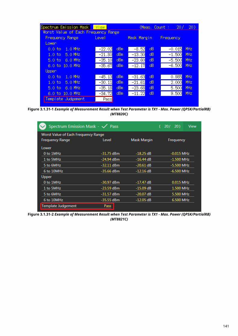
Figure 3.1.31-1 Example of Measurement Result when Test Parameter is TX1 - Max. Power (QPSK/PartialRB)
(MT8820C)
Figure 3.1.31-2 Example of Measurement Result when Test Parameter is TX1 - Max. Power (QPSK/PartialRB)
(MT8821C)
141
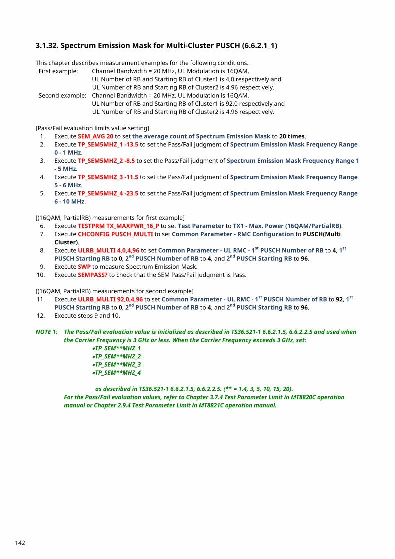
Spectrum Emission Mask for Multi-Cluster PUSCH (6.6.2.1_1) 3.1.32. This chapter describes measurement examples for the following conditions. First example: Channel Bandwidth = 20 MHz, UL Modulation is 16QAM,
UL Number of RB and Starting RB of Cluster1 is 4,0 respectively and UL Number of RB and Starting RB of Cluster2 is 4,96 respectively.
Second example: Channel Bandwidth = 20 MHz, UL Modulation is 16QAM, UL Number of RB and Starting RB of Cluster1 is 92,0 respectively and UL Number of RB and Starting RB of Cluster2 is 4,96 respectively.
[Pass/Fail evaluation limits value setting]
1. Execute SEM_AVG 20 to set the average count of Spectrum Emission Mask to 20 times. 2. Execute TP_SEM5MHZ_1 -13.5 to set the Pass/Fail judgment of Spectrum Emission Mask Frequency Range
0 - 1 MHz. 3. Execute TP_SEM5MHZ_2 -8.5 to set the Pass/Fail judgment of Spectrum Emission Mask Frequency Range 1
- 5 MHz. 4. Execute TP_SEM5MHZ_3 -11.5 to set the Pass/Fail judgment of Spectrum Emission Mask Frequency Range
5 - 6 MHz. 5. Execute TP_SEM5MHZ_4 -23.5 to set the Pass/Fail judgment of Spectrum Emission Mask Frequency Range
6 - 10 MHz. [(16QAM, PartialRB) measurements for first example]
6. Execute TESTPRM TX_MAXPWR_16_P to set Test Parameter to TX1 - Max. Power (16QAM/PartialRB). 7. Execute CHCONFIG PUSCH_MULTI to set Common Parameter - RMC Configuration to PUSCH(Multi
Cluster). 8. Execute ULRB_MULTI 4,0,4,96 to set Common Parameter - UL RMC - 1st PUSCH Number of RB to 4, 1st
PUSCH Starting RB to 0, 2nd PUSCH Number of RB to 4, and 2nd PUSCH Starting RB to 96. 9. Execute SWP to measure Spectrum Emission Mask.
10. Execute SEMPASS? to check that the SEM Pass/Fail judgment is Pass. [(16QAM, PartialRB) measurements for second example] 11. Execute ULRB_MULTI 92,0,4,96 to set Common Parameter - UL RMC - 1st PUSCH Number of RB to 92, 1st
PUSCH Starting RB to 0, 2nd PUSCH Number of RB to 4, and 2nd PUSCH Starting RB to 96. 12. Execute steps 9 and 10. NOTE 1: The Pass/Fail evaluation value is initialized as described in TS36.521-1 6.6.2.1.5, 6.6.2.2.5 and used when
the Carrier Frequency is 3 GHz or less. When the Carrier Frequency exceeds 3 GHz, set: •TP_SEM**MHZ_1 •TP_SEM**MHZ_2 •TP_SEM**MHZ_3 •TP_SEM**MHZ_4 as described in TS36.521-1 6.6.2.1.5, 6.6.2.2.5. (** = 1.4, 3, 5, 10, 15, 20).
For the Pass/Fail evaluation values, refer to Chapter 3.7.4 Test Parameter Limit in MT8820C operation manual or Chapter 2.9.4 Test Parameter Limit in MT8821C operation manual.
142
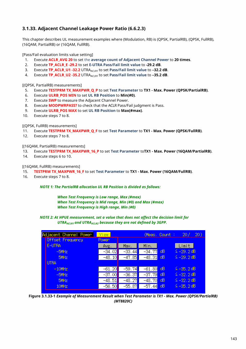
Adjacent Channel Leakage Power Ratio (6.6.2.3) 3.1.33. This chapter describes UL measurement examples where (Modulation, RB) is (QPSK, PartialRB), (QPSK, FullRB), (16QAM, PartialRB) or (16QAM, FullRB). [Pass/Fail evaluation limits value setting]
1. Execute ACLR_AVG 20 to set the average count of Adjacent Channel Power to 20 times. 2. Execute TP_ACLR_E -29.2 to set E-UTRA Pass/Fail limit value to -29.2 dB. 3. Execute TP_ACLR_U1 -32.2 UTRAACLR1 to set Pass/Fail limit value to –32.2 dB. 4. Execute TP_ACLR_U2 -35.2 UTRAACLR1 to set Pass/Fail limit value to –35.2 dB.
[(QPSK, PartialRB) measurements]
5. Execute TESTPRM TX_MAXPWR_Q_P to set Test Parameter to TX1 - Max. Power (QPSK/PartialRB). 6. Execute ULRB_POS MIN to set UL RB Position to Min(#0). 7. Execute SWP to measure the Adjacent Channel Power. 8. Execute MODPWRPASS? to check that the ACLR Pass/Fail judgment is Pass. 9. Execute ULRB_POS MAX to set UL RB Position to Max(#max).
10. Execute steps 7 to 8. [(QPSK, FullRB) measurements] 11. Execute TESTPRM TX_MAXPWR_Q_F to set Test Parameter to TX1 - Max. Power (QPSK/FullRB). 12. Execute steps 7 to 8. [(16QAM, PartialRB) measurements] 13. Execute TESTPRM TX_MAXPWR_16_P to set Test Parameter toTX1 - Max. Power (16QAM/PartialRB). 14. Execute steps 6 to 10. [(16QAM, FullRB) measurements] 15. TESTPRM TX_MAXPWR_16_F to set Test Parameter to TX1 - Max. Power (16QAM/FullRB). 16. Execute steps 7 to 8. NOTE 1: The PartialRB allocation UL RB Position is divided as follows: When Test Frequency is Low range, Max (#max) When Test Frequency is Mid range, Min (#0) and Max (#max) When Test Frequency is High range, Min (#0)
NOTE 2: At HPUE measurement, set a value that does not affect the decision limit for UTRAACLR1 and UTRAACLR2 because they are not defined by 3GPP.
Figure 3.1.33-1 Example of Measurement Result when Test Parameter is TX1 - Max. Power (QPSK/PartialRB)
(MT8820C)
143
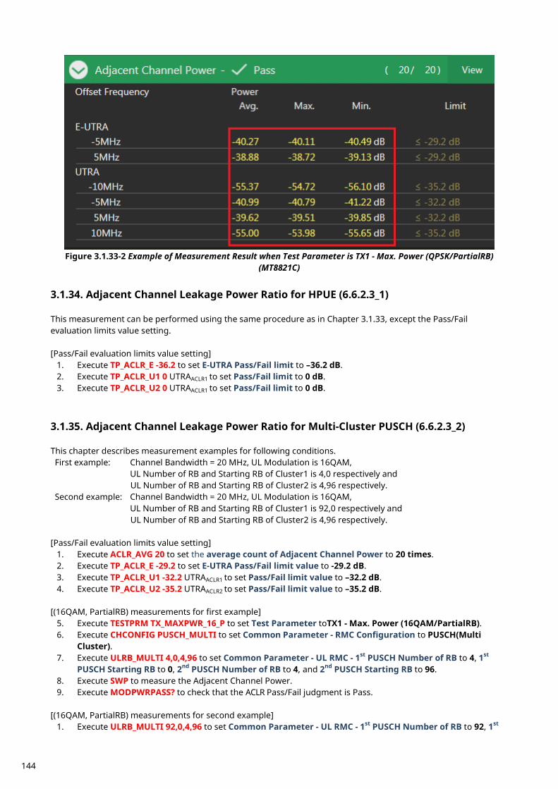
Figure 3.1.33-2 Example of Measurement Result when Test Parameter is TX1 - Max. Power (QPSK/PartialRB)
(MT8821C)
Adjacent Channel Leakage Power Ratio for HPUE (6.6.2.3_1) 3.1.34. This measurement can be performed using the same procedure as in Chapter 3.1.33, except the Pass/Fail evaluation limits value setting. [Pass/Fail evaluation limits value setting]
1. Execute TP_ACLR_E -36.2 to set E-UTRA Pass/Fail limit to –36.2 dB. 2. Execute TP_ACLR_U1 0 UTRAACLR1 to set Pass/Fail limit to 0 dB. 3. Execute TP_ACLR_U2 0 UTRAACLR1 to set Pass/Fail limit to 0 dB.
Adjacent Channel Leakage Power Ratio for Multi-Cluster PUSCH (6.6.2.3_2) 3.1.35. This chapter describes measurement examples for following conditions. First example: Channel Bandwidth = 20 MHz, UL Modulation is 16QAM,
UL Number of RB and Starting RB of Cluster1 is 4,0 respectively and UL Number of RB and Starting RB of Cluster2 is 4,96 respectively.
Second example: Channel Bandwidth = 20 MHz, UL Modulation is 16QAM, UL Number of RB and Starting RB of Cluster1 is 92,0 respectively and UL Number of RB and Starting RB of Cluster2 is 4,96 respectively.
[Pass/Fail evaluation limits value setting]
1. Execute ACLR_AVG 20 to set the average count of Adjacent Channel Power to 20 times. 2. Execute TP_ACLR_E -29.2 to set E-UTRA Pass/Fail limit value to -29.2 dB. 3. Execute TP_ACLR_U1 -32.2 UTRAACLR1 to set Pass/Fail limit value to –32.2 dB. 4. Execute TP_ACLR_U2 -35.2 UTRAACLR2 to set Pass/Fail limit value to –35.2 dB.
[(16QAM, PartialRB) measurements for first example]
5. Execute TESTPRM TX_MAXPWR_16_P to set Test Parameter toTX1 - Max. Power (16QAM/PartialRB). 6. Execute CHCONFIG PUSCH_MULTI to set Common Parameter - RMC Configuration to PUSCH(Multi
Cluster). 7. Execute ULRB_MULTI 4,0,4,96 to set Common Parameter - UL RMC - 1st PUSCH Number of RB to 4, 1st
PUSCH Starting RB to 0, 2nd PUSCH Number of RB to 4, and 2nd PUSCH Starting RB to 96. 8. Execute SWP to measure the Adjacent Channel Power. 9. Execute MODPWRPASS? to check that the ACLR Pass/Fail judgment is Pass.
[(16QAM, PartialRB) measurements for second example]
1. Execute ULRB_MULTI 92,0,4,96 to set Common Parameter - UL RMC - 1st PUSCH Number of RB to 92, 1st
144
PUSCH Starting RB to 0, 2nd PUSCH Number of RB to 4, and 2nd PUSCH Starting RB to 96. 2. Execute steps 8 and 9.
Adjacent Channel Leakage power Ratio for UL 64QAM (6.6.2.3_3) 3.1.36. This chapter describes UL measurement examples where (Modulation, RB) is (64QAM, PartialRB) or (64QAM, FullRB). [Pass/Fail evaluation limits value setting]
1. Execute ACLR_AVG 20 to set the average count of Adjacent Channel Power to 20 times. 2. Execute TP_ACLR_E -29.2 to set E-UTRA Pass/Fail limit value to –29.2 dB. 3. Execute TP_ACLR_U1 -32.2 UTRAACLR1 to set Pass/Fail limit value to –32.2 dB. 4. Execute TP_ACLR_U2 -35.2 UTRAACLR1 to set Pass/Fail limit value to –35.2 dB.
[(64QAM, PartialRB) measurements]
5. Execute TESTPRM TX_MAXPWR_64_P to set Test Parameter to TX1 - Max. Power (64QAM/PartialRB). 6. Execute ULRB_POS MIN to set UL RB Position to Min(#0). 7. Execute SWP to measure the Adjacent Channel Power. 8. Execute MODPWRPASS? to check that the ACLR Pass/Fail judgment is Pass. 9. Execute ULRB_POS MAX to set UL RB Position to Max(#max).
10. Execute steps 7 to 8. [(64QAM, FullRB) measurements] 11. Execute TESTPRM TX_MAXPWR_64_F to set Test Parameter to TX1 - Max. Power (64QAM/FullRB). 12. Execute steps 7 to 8. NOTE 1: The UL RB Position for PartialRB allocation is Min (#0) or Max (#Max).
Adjacent Channel Leakage power Ratio for Multi-Cluster PUSCH with UL 64QAM 3.1.37.(6.6.2.3_4) This chapter describes measurement examples for following conditions. First example: Channel Bandwidth = 20 MHz, UL Modulation is 64QAM,
UL Number of RB and Starting RB of Cluster1 is 4,0 respectively and UL Number of RB and Starting RB of Cluster2 is 4,96 respectively.
Second example: Channel Bandwidth = 20 MHz, UL Modulation is 64QAM, UL Number of RB and Starting RB of Cluster1 is 92,0 respectively and UL Number of RB and Starting RB of Cluster2 is 4,96 respectively.
[Pass/Fail evaluation limits value setting]
1. Execute ACLR_AVG 20 to set the average count of Adjacent Channel Power to 20 times. 2. Execute TP_ACLR_E -29.2 to set E-UTRA Pass/Fail limit value to –29.2 dB. 3. Execute TP_ACLR_U1 -32.2 UTRAACLR1 to set Pass/Fail limit value to –32.2 dB. 4. Execute TP_ACLR_U2 -35.2 UTRAACLR2 to set Pass/Fail limit value to –35.2 dB.
[Measurements for the first example]
5. Execute TESTPRM TX_MAXPWR_64_P to set Test Parameter toTX1 - Max. Power (64QAM/PartialRB). 6. Execute CHCONFIG PUSCH_MULTI to set Common Parameter - RMC Configuration to PUSCH(Multi
Cluster). 7. Execute ULRB_MULTI 4,0,4,96 to set Common Parameter - UL RMC - 1st PUSCH Number of RB to 4, 1st
PUSCH Starting RB to 0, 2nd PUSCH Number of RB to 4, and 2nd PUSCH Starting RB to 96. 8. Execute SWP to measure the Adjacent Channel Power. 9. Execute MODPWRPASS? to check that the ACLR Pass/Fail judgment is Pass.
[Measurements for the second example] 10. Execute ULRB_MULTI 92,0,4,96 to set Common Parameter - UL RMC - 1st PUSCH Number of RB to 92, 1st
145
PUSCH Starting RB to 0, 2nd PUSCH Number of RB to 4, and 2nd PUSCH Starting RB to 96. 11. Execute steps 8 and 9.
NOTE 1: The UL RB Position for PartialRB allocation differs depending on the Configuration ID at TS36.521–1 Table 6.6.2.3_4.4.1-1.
Additional Maximum Power Reduction (A-MPR) (6.2.4) 3.1.38. Because there are no test parameters supporting Additional Maximum Power Reduction tests and Additional Spectrum Emission Mask tests, select the basic parameter (TX1 - Max. Power (QPSK/FullRB)) and set parameters and standard values required for the test individually. This chapter describes UL measurement examples where (Modulation, RB) are (QPSK, PartialRB), (QPSK, FullRB), (16QAM, PartialRB) or(16QAM, FullRB) when additionalSpectrumEmission is NS_03 and Test Frequency is Mid range.
1. Execute BAND 2 to set Operating Band to 2. 2. Execute PWR_AVG 20 to set the average count of Power Measurement to 20 times. 3. Execute SEM_AVG 20 to set the average count of Spectrum Emission Mask to 20 times. 4. Execute TESTPRM TX_MAXPWR_Q_F to set Test parameter to TX1 - Max. Power(QPSK/FullRB). 5. Execute ALLMEASITEMS_OFF to set all fundamental measurement items to OFF. 6. Execute PWR_MEAS ON to set Power measurement to ON. 7. Execute SEM_MEAS ON to set Spectrum Emission Mask measurement to ON. 8. Execute SIB2_NS NS_03 to set additionalSpectrumEmission to NS_03.
[(QPSK, PartialRB) measurements]
9. Execute ULRMC_MOD QPSK to set UL RMC modulation to QPSK. 10. Execute ULRMC_RB 8 to set UL RB number to 8. 11. Execute ULRB_POS MIN to set UL RB Position to Min(#0). 12. Execute TP_MPR1_UL 25.7 to set TX Power measurement Pass/Fail upper limit to 25.7 dBm. 13. Execute TP_MPR1_LL 19.3 to set TX Power measurement Pass/Fail lower limit 19.3 dBm. 14. Execute SWP to measure the power. 15. Execute POWER? AVG to read the Tx Power measurement result. 16. Execute POWERPASS? to check the measurement result is PASS. 17. Execute SEMPASS? to check the SEM result is PASS. 18. Execute ULRB_POS MAX to set UL RB Position to Max (#max). 19. Execute step 14 to 17. 20. Execute ULRMC_RB 6 to set UL RB number to 6. 21. Execute ULRB_POS MIN to set UL RB Position to Min(#0). 22. Execute TP_MPR1_UL 25.7 to set TX Power measurement Pass/Fail upper limit to 25.7 dBm. 23. Execute TP_MPR1_LL 20.3 to set TX Power measurement Pass/Fail lower limit 20.3 dBm. 24. Execute step 14 to 17. 25. Execute ULRB_POS MAX to set UL RB Position to Max(#max). 26. Execute steps 14 to 17. [(QPSK, FullRB) measurements] 27. Execute ULRMC_RB 25 to set UL RB number to 25. 28. Execute TP_MPR1_UL 25.7 to set TX Power measurement Pass/Fail upper limit to 25.7 dBm. 29. Execute TP_MPR1_LL 18.3 to set TX Power measurement Pass/Fail lower limit to 18.3 dBm. 30. Execute steps 14 to 17. [(16QAM, PartialRB) measurements] 31. Execute ULRMC_MOD 16QAM to set UL RMC modulation method to 16QAM. 32. Execute ULRMC_RB 8 to set UL RB number to 8. 33. Execute ULRB_POS MIN to set UL RB Position to Min (#0). 34. Execute TP_MPR1_UL 25.7 to set TX Power measurement Pass/Fail upper limit to 25.7 dBm. 35. Execute TP_MPR1_LL 18.3 to set TX Power measurement Pass/Fail lower limit to 18.3 dBm. 36. Execute steps 14 to 17. 37. Execute ULRB_POS MAX to set UL RB Position to Max (#max).
146
38. Execute steps 14 to 17. [(16QAM, FullRB) measurements] 39. Execute ULRMC_RB 25 to set UL RB number to 25. 40. Execute TP_MPR1_UL 25.7 to set TX Power measurement Pass/Fail upper limit to 25.7 dBm. 41. Execute TP_MPR1_LL 16.8 to set TX Power measurement Pass/Fail lower limit to 16.8 dBm. 42. Execute steps 14 to 17. NOTE 1: The UL RB Position for PartialRB allocation differs depending on the Configuration ID at
TS36.521–1 Table 6. 2. 4.4.1-1 through 6.2.4.4.1-19. NOTE 2: There is no need to set separately because the Pass/Fail evaluation value for Spectrum Emission Mask measurement changes in accordance with the additionalSpectrumEmission setting.
NOTE 3: The usual Pass/Fail evaluation value is set to the Band 1 default value described in TS36.521-1. Since the evaluation value differs according to the Band, set the evaluation value described in
TS36.521-1 Table 6.2.4.5-1 at: TP_MPR1_LL TP_MPR1_UL
For the Pass/Fail evaluation values, refer to Chapter 3.7.4 Test Parameter Limit in MT8820C operation manual or Chapter 2.9.4 Test Parameter Limit in MT8821C operation manual.
Additional Maximum Power Reduction (A-MPR) for HPUE (6.2.4_1) 3.1.39. Because there are no test parameters supporting Additional Maximum Power Reduction for HPUE test, select the basic parameter (TX1 - Max. Power (QPSK/FullRB)) and set parameters and the pass/fail evaluation limits for each test condition/requirement. This chapter describes UL measurement examples where (Modulation, RB) are (QPSK, PartialRB), (QPSK, FullRB), (16QAM, PartialRB) or (16QAM, FullRB) when additionalSpectrumEmission is NS_06 and Test Frequency is Mid range.
1. Execute BAND 14 to set Operating Band to 2. 2. Execute PWR_AVG 20 to set the average count of power measurement to 20 times. 3. Execute SEM_AVG 20 to set the average count of Spectrum Emission Mask to 20 times. 4. Execute TESTPRM TX_MAXPWR_Q_F to set Test parameter to TX1 - Max. Power (QPSK/FullRB). 5. Execute ALLMEASITEMS_OFF to set fundamental measurement items to OFF at one time. 6. Execute PWR_MEAS ON to set Power measurement to ON. 7. Execute SEM_MEAS ON to set Spectrum Emission Mask measurement to ON. 8. Execute SIB2_NS NS_06 to set additionalSpectrumEmission to NS_06.
[(QPSK, PartialRB) measurements]
9. Execute ULRMC_MOD QPSK to set UL RMC modulation to QPSK. 10. Execute ULRMC_RB 8 to set UL RB number to 8. 11. Execute ULRB_POS MIN to set UL RB Position to Min (#0). 12. Execute TP_MPR1_UL 33.7 to set TX Power measurement Pass/Fail upper limit to 33.7 dBm. 13. Execute TP_MPR1_LL 26.3 to set TX Power measurement Pass/Fail lower limit to 26.3 dBm. 14. Execute SWP to measure the power. 15. Execute POWER? AVG to read the TX Power measurement result. 16. Execute POWERPASS? to check the measurement result is PASS. 17. Execute SEMPASS? to check the SEM result is PASS. 18. Execute ULRB_POS MAX to set UL RB Position to Max (#max). 19. Execute step 14 to 17.
147

[(QPSK, FullRB) measurements] 20. Execute ULRMC_RB 25 to set UL RB number to 25. 21. Execute TP_MPR1_UL 33.7 to set TX Power measurement Pass/Fail upper limit to 33.7 dBm. 22. Execute TP_MPR1_LL 26.3 to set TX Power measurement Pass/Fail lower limit to 26.3 dBm. 23. Execute steps 14 to 17. [(16QAM, PartialRB) measurements] 24. Execute ULRMC_MOD 16QAM to set UL RMC modulation method to 16QAM. 25. Execute ULRMC_RB 8 to set UL RB number to 8. 26. Execute ULRB_POS MIN to set UL RB Position to Min(#0). 27. Execute TP_MPR1_UL 33.7 to set TX Power measurement Pass/Fail upper limit to 33.7 dBm. 28. Execute TP_MPR1_LL 26.3 to set TX Power measurement Pass/Fail lower limit to 26.3 dBm. 29. Execute steps 14 to 17. 30. Execute ULRB_POS MAX to set UL RB Position to Max(#max). 31. Execute steps 14 to 17.
NOTE 1: The UL RB Position for PartialRB allocation is divided as follows: When Test Frequency is Low range, Max (#max) When Test Frequency is Mid range, Min (#0) and Max (#max) When Test Frequency is High range, Min (#0)
NOTE 2: There is no need to set separately because the Pass/Fail evaluation value for Spectrum Emission Mask measurement changes in accordance with the additionalSpectrumEmission setting.
NOTE 3: The usual Pass/Fail evaluation value is set to the Band 1 default value described in TS36.521-1. Since the evaluation value differs according to the Band, set the evaluation value described in
TS36.521-1 Table 6.2.4_1.5-1 at: TP_MPR1_LL TP_MPR1_UL
For the Pass/Fail evaluation values, refer to Chapter 3.7.4 Test Parameter Limit in MT8820C operation manual or Chapter 2.9.4 Test Parameter Limit in MT8821C operation manual.
Additional Maximum Power Reduction (A-MPR) for UL 64QAM (6.2.4_2) 3.1.40. Because there are no test parameters supporting Additional Maximum Power Reduction for UL 64QAM test, select the basic parameter (TX1 - Max. Power (64QAM/FullRB)) and set parameters and the pass/fail evaluation limits for each test condition/requirement. This chapter describes UL measurement examples where (Modulation, RB) are (64QAM, PartialRB) or (64QAM, FullRB) when additionalSpectrumEmission is NS_03 and Test Frequency is Mid range.
1. Execute BAND 2 to set Operating Band to 2. 2. Execute PWR_AVG 20 to set the average count of Power Measurement to 20 times. 3. Execute SEM_AVG 20 to set the average count of Spectrum Emission Mask to 20 times. 4. Execute TESTPRM TX_MAXPWR_64_F to set Test parameter to TX1 - Max. Power(64QAM/FullRB). 5. Execute ALLMEASITEMS_OFF to set all fundamental measurement items to OFF. 6. Execute PWR_MEAS ON to set Power measurement to ON. 7. Execute SEM_MEAS ON to set Spectrum Emission Mask measurement to ON. 8. Execute SIB2_NS NS_03 to set additionalSpectrumEmission to NS_03.
[(64QAM, PartialRB) measurements]
9. Execute ULRMC_MOD 64QAM to set UL RMC modulation to 64QAM. 10. Execute ULRMC_RB 8 to set UL RB number to 8. 11. Execute ULRB_POS MIN to set UL RB Position to Min(#0). 12. Execute TP_MPR5_UL 25.7 to set TX Power measurement Pass/Fail upper limit to 25.7 dBm. 13. Execute TP_MPR5_LL 16.8 to set TX Power measurement Pass/Fail lower limit 16.8 dBm.
148
14. Execute SWP to measure the power. 15. Execute POWER? AVG to read the Tx Power measurement result. 16. Execute POWERPASS? to check the measurement result is PASS. 17. Execute SEMPASS? to check the SEM result is PASS. 18. Execute ULRB_POS MAX to set UL RB Position to Max (#max). 19. Execute step 14 to 17. [(64QAM, FullRB) measurements] 20. Execute ULRMC_RB 25 to set UL RB number to 25. 21. Execute TP_MPR5_UL 25.7 to set TX Power measurement Pass/Fail upper limit to 25.7 dBm. 22. Execute TP_MPR5_LL 14.8 to set TX Power measurement Pass/Fail lower limit to 14.8 dBm. 23. Execute steps 14 to 17. NOTE 1: The UL RB Position for PartialRB allocation differs depending on the Configuration ID at
TS36.521–1 Table 6. 2. 4_2.4.1-1 to 6.2.4_2.4.1-19.
NOTE 2: There is no need to set separately because the Pass/Fail evaluation value for Spectrum Emission Mask measurement changes in accordance with the additionalSpectrumEmission setting.
NOTE 3: The usual Pass/Fail evaluation value is set to the Band 1 default value described in TS36.521-1. Since the evaluation value differs according to the Band, set the evaluation value described in
TS36.521-1 Table 6.2.4_2.5-1 to 6.2.4_2.5-21 at: TP_MPR5_LL TP_MPR5_UL
For the Pass/Fail evaluation values, refer to Chapter 3.7.4 Test Parameter Limit in MT8820C operation manual or Chapter 2.9.4 Test Parameter Limit in MT8821C operation manual.
Additional Spectrum Emission Mask (6.6.2.2) 3.1.41. This measurement can be performed using the same procedure as in Chapter 3.1.38.
Additional Spectrum Emission Mask for UL 64QAM (6.6.2.2_1) 3.1.42. This measurement can be performed using the same procedure as in Chapter 3.1.40.
149
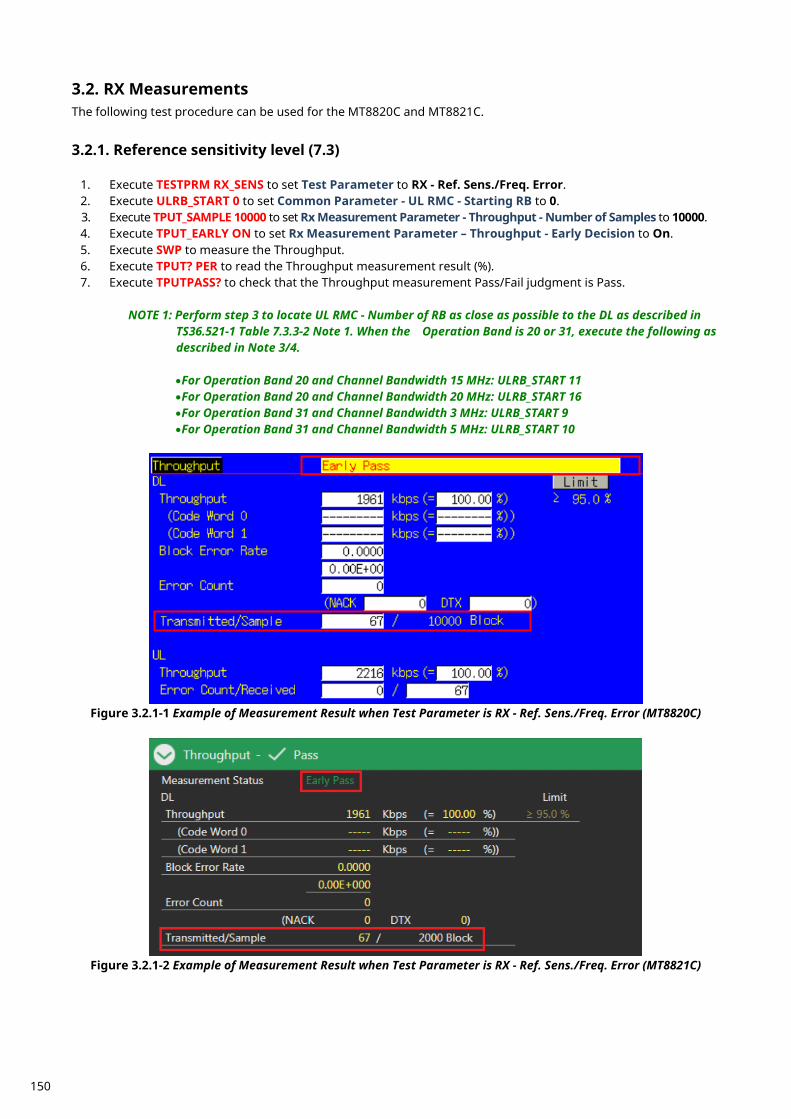
RX Measurements 3.2.The following test procedure can be used for the MT8820C and MT8821C.
Reference sensitivity level (7.3) 3.2.1.
1. Execute TESTPRM RX_SENS to set Test Parameter to RX - Ref. Sens./Freq. Error. 2. Execute ULRB_START 0 to set Common Parameter - UL RMC - Starting RB to 0. 3. Execute TPUT_SAMPLE 10000 to set Rx Measurement Parameter - Throughput - Number of Samples to 10000. 4. Execute TPUT_EARLY ON to set Rx Measurement Parameter – Throughput - Early Decision to On. 5. Execute SWP to measure the Throughput. 6. Execute TPUT? PER to read the Throughput measurement result (%). 7. Execute TPUTPASS? to check that the Throughput measurement Pass/Fail judgment is Pass.
NOTE 1: Perform step 3 to locate UL RMC - Number of RB as close as possible to the DL as described in
TS36.521-1 Table 7.3.3-2 Note 1. When the Operation Band is 20 or 31, execute the following as described in Note 3/4.
•For Operation Band 20 and Channel Bandwidth 15 MHz: ULRB_START 11 •For Operation Band 20 and Channel Bandwidth 20 MHz: ULRB_START 16 •For Operation Band 31 and Channel Bandwidth 3 MHz: ULRB_START 9 •For Operation Band 31 and Channel Bandwidth 5 MHz: ULRB_START 10
Figure 3.2.1-1 Example of Measurement Result when Test Parameter is RX - Ref. Sens./Freq. Error (MT8820C)
Figure 3.2.1-2 Example of Measurement Result when Test Parameter is RX - Ref. Sens./Freq. Error (MT8821C)
150
Maximum input level with 4 Rx antenna ports (7.4_1) 3.2.2. The following test configuration example shows the settings when Operating Band is 3, Test Frequency is Mid range, and Test Channel Bandwidth is 5 MHz.
1. Execute BAND 3 to set Common Parameter - Frequency – Operation Band to 3. 2. Execute TESTPRM RX_SENS to set Test Parameter to RX - Ref. Sens./Freq. Error. 3. Execute ULRB_START 0 to set Common Parameter - Level – Output Level to -99.0. 4. Execute OLVL -99.0 to set Common Parameter - Frequency – Operation Band to 3. 5. Execute TPUT_SAMPLE 10000 to set Rx Measurement Parameter - Throughput - Number of Samples to 10000. 6. Execute TPUT_EARLY ON to set Rx Measurement Parameter – Throughput - Early Decision to On. 7. Execute SWP to measure the Throughput. 8. Execute TPUT? PER to read the Throughput measurement result (%). 9. Execute TPUTPASS? to check that the Throughput measurement Pass/Fail judgment is Pass.
NOTE 1: Perform step 3 to locate UL RMC - Number of RB as close as possible to the DL as described in
TS36.521-1 Table 7.3.3-2 Note 1. When the Operation Band is 20 or 31, execute the following as described in Note 3/4.
•For Operation Band 20 and Channel Bandwidth 15 MHz: ULRB_START 11 •For Operation Band 20 and Channel Bandwidth 20 MHz: ULRB_START 16 •For Operation Band 31 and Channel Bandwidth 3 MHz: ULRB_START 9 •For Operation Band 31 and Channel Bandwidth 5 MHz: ULRB_START 10
NOTE 2: Since the output power depends on the Operation Bnad and Channel bandwidth, set the output
power according to TS 36.521-1 Table 7.3_1.5.1.
Maximum input level (7.4) 3.2.3.
1. Execute TESTPRM RX_MAX to set Test Parameter to RX - Max. Input Level. 2. Execute ULRB_START 0 to set Common Parameter - UL RMC - Starting RB to 0. 3. Execute TPUT_SAMPLE 10000 to set Rx Measurement Parameter - Throughput - Number of Sample to
10000. 4. Execute TPUT_EARLY ON to set Rx Measurement Parameter - Throughput - Early Decision to On. 5. Execute SWP to measure the Throughput. 6. Execute TPUT? PER to read the Throughput measurement result (%). 7. Execute TPUTPASS? to check that the Throughput measurement Pass/Fail judgment is Pass.
NOTE 1: When the Carrier Frequency exceeds 3 GHz, set:
•Output Level –26.0 dBm as described in TS36.521-1 Table 7.4.5-1.
NOTE 2: Perform step 3 to locate UL RMC - Number of RB as close as possible to the DL as described in
TS36.521-1 Table 7.3.3-2 Note 1. When the Operation Band is 20 or 31, execute the following as described in Note 3/4.
•For Operation Band 20 and Channel Bandwidth 15 MHz: ULRB_START 11 •For Operation Band 20 and Channel Bandwidth 20 MHz: ULRB_START 16 •For Operation Band 31 and Channel Bandwidth 3 MHz: ULRB_START 9 •For Operation Band 31 and Channel Bandwidth 5 MHz: ULRB_START 10
151
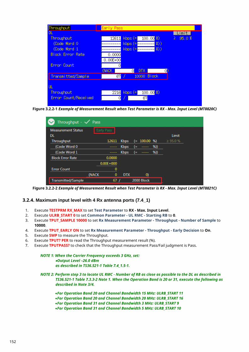
Figure 3.2.2-1 Example of Measurement Result when Test Parameter is RX - Max. Input Level (MT8820C)
Figure 3.2.2-2 Example of Measurement Result when Test Parameter is RX - Max. Input Level (MT8821C)
Maximum input level with 4 Rx antenna ports (7.4_1) 3.2.4.
1. Execute TESTPRM RX_MAX to set Test Parameter to RX - Max. Input Level. 2. Execute ULRB_START 0 to set Common Parameter - UL RMC - Starting RB to 0. 3. Execute TPUT_SAMPLE 10000 to set Rx Measurement Parameter - Throughput - Number of Sample to
10000. 4. Execute TPUT_EARLY ON to set Rx Measurement Parameter - Throughput - Early Decision to On. 5. Execute SWP to measure the Throughput. 6. Execute TPUT? PER to read the Throughput measurement result (%). 7. Execute TPUTPASS? to check that the Throughput measurement Pass/Fail judgment is Pass.
NOTE 1: When the Carrier Frequency exceeds 3 GHz, set:
•Output Level –26.0 dBm as described in TS36.521-1 Table 7.4_1.5-1.
NOTE 2: Perform step 3 to locate UL RMC - Number of RB as close as possible to the DL as described in
TS36.521-1 Table 7.3.3-2 Note 1. When the Operation Band is 20 or 31, execute the following as described in Note 3/4.
•For Operation Band 20 and Channel Bandwidth 15 MHz: ULRB_START 11 •For Operation Band 20 and Channel Bandwidth 20 MHz: ULRB_START 16 •For Operation Band 31 and Channel Bandwidth 3 MHz: ULRB_START 9 •For Operation Band 31 and Channel Bandwidth 5 MHz: ULRB_START 10
152
Maximum input level for 256QAM in DL (7.4_H) (MT8821C Only) 3.2.5.
1. Execute DLRMC_256QAM to set DL RMC – 256QAM to Enabled. 2. Execute TESTPRM RX_MAX to set Test Parameter to RX - Max. Input Level. 3. Execute ULRB_START 0 to set Common Parameter - UL RMC - Starting RB to 0. 4. Execute OLVL -27.7 to set Common Parameter - Output Level to -27.7dBm. 5. Execute TPUT_SAMPLE 10000 to set Rx Measurement Parameter - Throughput - Number of Sample to
10000. 6. Execute TPUT_EARLY ON to set Rx Measurement Parameter - Throughput - Early Decision to On. 7. Execute SWP to measure the Throughput. 8. Execute TPUT? PER to read the Throughput measurement result (%). 9. Execute TPUTPASS? to check that the Throughput measurement Pass/Fail judgment is Pass.
NOTE 1: When the Carrier Frequency exceeds 3 GHz, set:
•Output Level –28.0 dBm as described in TS36.521-1 Table 7.4_H.5-1.
Spurious emissions (7.9) 3.2.6. Perform Rx spurious emission tests using an external spectrum analyzer.
1. Connect the MT8821C, spectrum analyzer and UE. 2. Execute CALLDROP OFF to set Call Processing Parameter - Call Drop function to OFF. 3. Execute ULRMC_RB 0 to set Common Parameter - UL RMC - Number of RB to 0. 4. Execute DLRMC_RB 0 to set Common Parameter - DL RMC - Number of RB to 0. 5. Measure the Rx spurious emissions using the spectrum analyzer. 6. Check that maximum level at each frequency bandwidth is lower than the standardized value.
NOTE 1: Refer to 3GPP TS36.508 Annex A, Figure A.8 for the connection between the MT8821C, spectrum analyzer and UE.
153

TX Measurements for CA 3.3.
TX Measurements for Inter-band CA 3.3.1.This chapter explains the test procedure for Inter–band CA measurement specified in 3GPP TS 36.521–1. On the MT8821C, available argument of Pass/Fail limit value setting varies according to CA Configuration (Inter-band CA, Intra-band contiguous CA or Intra-band non-contiguous CA). For details, refer to Chapter 3.10.
Table 3.3-1: Available argument according to CA Configuration CA Configuration Argument MT8820C MT8821C
Inter-band CA INTER — ✓ Intra-band contiguous CA CONTCC — ✓
Intra-band non-contiguous CA NONCONT — ✓ The following test procedures are different between the MT8820C and MT8821C. This chapter explains each test procedure for the MT8820C and MT8821C. 3.3.1.1. UE Maximum Output Power for CA (inter-band DL CA and UL CA) (6.2.2A.2) 3.3.1.1.1. MT8820C This measurement item is not supported by MT8820C. Refer to Chapter 1.2. Measurement result for each CC can be obtained by following procedure. [Acceptable Value Setting] 1. [PCC/SCC] Execute PWR_AVG 20 to set the average count for Power Measurement to 20 2. [PCC/SCC] Execute TP_MAXPWR_LL 19.3 to set TX1 – Max. Power (QPSK/1RB/PartialRB) Pass/Fail lower limit
to 19.3 dBm. 3. [PCC/SCC] Execute TP_MAXPWR_UL 25.7 to set TX1 – Max. Power (QPSK/1RB/PartialRB) Pass/Fail upper
limit to 25.7 dBm. [(QPSK, 1RB) measurements] 4. [PCC/SCC] Execute TESTPRM TX_MAXPWR_Q_1 to set Test Parameter to TX1 – Max. Power (QPSK/1RB). 5. [PCC/SCC] Execute ULRMC_RB 1 to set UL RMC – Number of RB to 1. 6. [PCC/SCC] Execute ULRB_POS MIN to set UL RB Position to Min(#0). 7. [PCC/SCC] Execute SWP to measure the Power. 8. [PCC/SCC] Execute POWER? AVG to read the TX power measurement result. 9. [PCC/SCC] Execute POWERPASS? to check that the TX power measurement Pass/Fail judgment is Pass. [(QPSK, PartialRB) measurements] 10. [PCC/SCC] Execute TESTPRM TX_MAXPWR_Q_P to set Test Parameter to TX1 – Max. Power
(QPSK/PartialRB). 11. Execute steps 7 to 9. 3.3.1.1.2. MT8821C [Acceptable Value Setting]
1. Execute PWR_AVG 20 to set the average count for Power Measurement to 20 2. Execute TP_MAXPWR_LL 19.3, INTER to set TX1 – Max. Power (QPSK/1RB/PartialRB) Pass/Fail lower limit
to 19.3 dBm. 3. Execute TP_MAXPWR_UL 25.7, INTER to set TX1 – Max. Power (QPSK/1RB/PartialRB) Pass/Fail upper limit
to 25.7 dBm. [(QPSK, 1RB) measurements]
4. Execute TESTPRM TX_MAXPWR_Q_1 to set Test Parameter to TX1 – Max. Power(QPSK/1RB). 5. Execute ULRB_POS MIN to set PCC UL RB Position to Min(#0). 6. Execute ULRB_POS_SCC1 MIN to set SCC–1 UL RB Position to Min(#0). 7. Execute SWP to measure the Power. 8. Execute POWER? AVG to read the TX power measurement result.
154
9. Execute POWERPASS? to check that the TX power measurement Pass/Fail judgment is Pass.
NOTE 1: The PartialRB allocation UL RB Position is divided as follows: When Test Frequency is Low range, Min (#0) When Test Frequency is High range, Max (#max)
NOTE 2: Since the evaluation value differs according to E-UTRA CA Configuration, set the evaluation value
described in TS36.521-1 Table 6.2.2A.2.5-1 to: •TP_MAXPWR_LL •TP_MAXPWR_UL
NOTE 3: The tolerance (lower limit) can be relaxed by 1.5dB for transmission bandwidths confined within
FUL_low and FUL_low + 4 MHz or FUL_high – 4 MHz and FUL_high. 3.3.1.2. Maximum Power Reduction (MPR) for CA (inter-band DL CA and UL CA) (6.2.3A.2) This chapter describes the measurement examples for when the UL (Modulation, RB) is (QPSK, FullRB) or (16QAM, FullRB). Example (Partial RB): PCC NRB = 100, SCC NRB = 50, NRB_alloc = 30
PCC and SCC RB allocations (LCRB@RBstart) are P_18@0 and S_12@0, respectively 3.3.1.2.1. MT8820C This measurement item is not supported by MT8820C. Refer to Chapter 1.2. Measurement result for each CC can be obtained by following procedure. [Acceptable Value Setting]
1. [PCC/SCC] Execute PWR_AVG 20 to set average count of Power measurement to 20. 2. [PCC/SCC] Execute TP_MPR1_LL 19.3 to set TX1 – Max. Power (QPSK/FullRB) Pass/Fail lower limit to 19.3
dBm. 3. [PCC/SCC] Execute TP_MPR1_UL 25.7 to set TX1 – Max. Power (QPSK/FullRB) Pass/Fail upper limit to 25.7
dBm. 4. [PCC/SCC] Execute TP_MPR2_LL 19.3 to set TX1 – Max. Power (16QAM/PartialRB) Pass/Fail lower limit to
19.3 dBm. 5. [PCC/SCC] Execute TP_MPR2_UL 25.7 to set TX1 – Max. Power (16QAM/PartialRB) Pass/Fail upper limit to
25.7 dBm. 6. [PCC/SCC] Execute TP_MPR3_LL 19.3 to set TX1 - Max. Power (16QAM/FullRB) Pass/Fail lower limit to 19.3
dBm. 7. [PCC/SCC] Execute TP_MPR3_UL 25.7 to set TX1 - Max. Power (16QAM/FullRB) Pass/Fail upper limit to
25.7 dBm. [(QPSK, FullRB) measurements]
8. [PCC/SCC] Execute TESTPRM TX_MAXPWR_Q_F to set Test Parameter to TX1 – Max. Power(QPSK/FullRB). 9. [PCC/SCC] Execute SWP to measure the power.
10. [PCC/SCC] Execute POWER? AVG to read the TX power measurement result. 11. [PCC/SCC] Execute POWERPASS? to check that the TX power measurement Pass/Fail judgment is Pass. [(16QAM, PartialRB) measurements] 12. [PCC/SCC] Execute TESTPRM TX_MAXPWR_16_P to set Test Parameter to TX1 – Max. Power
(16QAM/PartialRB). 13. [PCC] Execute ULRMC_RB 18 to set Common Parameter – UL RMC – Number of RB to 18. 14. [SCC-1] Execute ULRMC_RB 12 to set Common Parameter – UL RMC – Number of RB to 12.
(For other Configuration ID setting, Set Common Parameter - PCC/SCC-1 – UL RMC-Number of RB and Starting RB according to TS36.521–1 Table 6.2.3A.2.4.1-1.)
15. Execute steps 9 to 11. [(16QAM, FullRB ) measurements] 16. [PCC/SCC] Execute TESTPRM TX_MAXPWR_16_F to set Test Parameter to TX1 – Max. Power
(16QAM/FullRB). 17. Execute steps 9 to 11.
155
3.3.1.2.2. MT8821C [Acceptable Value Setting]
1. Execute PWR_AVG 20 to set average count of Power measurement to 20. 2. Execute TP_MAXPWR_LL 19.3, INTER to set TX1 – Max. Power (QPSK/PartialRB) Pass/Fail lower limit to
19.3 dBm. 3. Execute TP_MAXPWR_UL 25.7, INTER to set TX1 – Max. Power (QPSK/PartialRB) Pass/Fail upper limit to
25.7 dBm. 4. Execute TP_MPR1_LL 19.3, INTER to set TX1 – Max. Power (QPSK/FullRB) Pass/Fail lower limit to 19.3
dBm. 5. Execute TP_MPR1_UL 25.7, INTER to set TX1 – Max. Power (QPSK/FullRB) Pass/Fail upper limit to 25.7
dBm. 6. Execute TP_MPR2_LL 19.3, INTER to set TX1 – Max. Power (16QAM/PartialRB) Pass/Fail lower limit to 19.3
dBm. 7. Execute TP_MPR2_UL 25.7, INTER to set TX1 – Max. Power (16QAM/PartialRB) Pass/Fail upper limit to
25.7 dBm. 8. Execute TP_MPR3_LL 19.3, INTER to set TX1 – Max. Power (16QAM/FullRB) Pass/Fail lower limit to 19.3
dBm. 9. Execute TP_MPR3_UL 25.7, INTER to set TX1 – Max. Power (16QAM/FullRB) Pass/Fail upper limit to 25.7
dBm. [(QPSK, PartialRB) measurements] 10. Execute TESTPRM TX_MAXPWR_Q_P to set Test Parameter to TX1 – Max. Power(QPSK/FullRB). 11. Execute ULRMC_RB 18 to set Common Parameter – UL RMC – Number of RB to 18. 12. Execute ULRMC_RB_SCC1 12 to set Common Parameter – SCC–1 – UL RMC – Number of RB to 12.
(For other Configuration ID setting, Set Common Parameter - PCC/SCC-1 – UL RMC-Number of RB and Starting RB according to TS36.521–1 Table 6.2.3A.2.4.1-1.)
13. Execute ULRB_POS MIN to set PCC UL RB Position to Min (#0). 14. Execute ULRB_POS_SCC1 MIN to set SCC-1 UL RB Position to Min (#0). 15. Execute SWP to measure the power. 16. Execute POWER? AVG to read the TX power measurement result. 17. Execute POWERPASS? to check that the TX power measurement Pass/Fail judgment is Pass. [(QPSK, FullRB) measurements] 18. Execute TESTPRM TX_MAXPWR_Q_F to set Test Parameter to TX1 – Max. Power(QPSK/FullRB). 19. Execute steps 15 to 17. [(16QAM, PartialRB) measurements] 20. Execute TESTPRM TX_MAXPWR_16_P to set Test Parameter to TX1 – Max. Power(16QAM/PartialRB). 21. Execute steps 11 to 17. [(16QAM, FullRB ) measurements] 22. Execute TESTPRM TX_MAXPWR_16_F to set Test Parameter to TX1 – Max. Power(16QAM/FullRB). 23. Execute steps 15 to 17.
NOTE 1: The PartialRB allocation UL RB Position is divided as follows: When Test Frequency is Low range, Min (#0) When Test Frequency is High range, Max (#max)
NOTE 1: Since the evaluation value differs according to the Configuration ID, set the evaluation value
described in TS36.521-1 Table 6.2.3A.2.5-1 to: •TP_MAXPWR_LL •TP_MAXPWR_UL •TP_MPR1_LL •TP_MPR1_UL •TP_MPR2_LL •TP_MPR2_UL •TP_MPR3_LL •TP_MPR3_UL
156
3.3.1.3. Additional Maximum Power Reduction (A-MPR) for CA (inter-band DL CA and UL CA) (6.2.4A.2) This chapter describes the measurement examples when for UL (Modulation, RB) is (QPSK, PartialRB), (QPSK, FullRB), (16QAM, PartialRB) or (16QAM, FullRB), additionalSpectrumEmission is NS_03, additionalSpectrumEmissionSCell is NS_03 and Test Frequency is Mid range. Example (Partial RB): PCC NRB = 100, SCC NRB = 100
PCC and SCC RB allocations (LCRB@RBstart) are P_10@0 and S_10@0, respectively 3.3.1.3.1. MT8820C 6.2.4A.2 is not supported by MT8820C (6.6.2.2A.2 is supported). Refer to Chapter 1.2. Measurement result for each CC can be obtained by following procedure.
1. [PCC/SCC] Execute PWR_AVG 20 to set the average count of Power Measurement to 20 times. 2. [PCC/SCC] Execute SEM_AVG 20 to set the average count of Spectrum Emission Mask to 20 times. 3. [PCC/SCC] Execute SIB2_NS NS_03 to set additionalSpectrumEmission to NS_03. 4. [PCC/SCC] Execute TESTPRM TX_MAXPWR_Q_F to set Test Parameter to TX1 – Max. Power(QPSK/FullRB). 5. [PCC/SCC] Execute ALLMEASITEMS_OFF to set all fundamental measurement items to OFF. 6. [PCC/SCC] Execute PWR_MEAS ON to set Power Measurement to ON. 7. [PCC/SCC] Execute SEM_MEAS ON to set Spectrum Emission Mask Measurement to ON.
[(QPSK, PartialRB/FullRB) measurements]
8. [PCC] Execute ULRMC_RB 10 to set Common Parameter – UL RMC – Number of RB to 10. 9. [SCC-1] Execute ULRMC_RB 10 to set Common Parameter – UL RMC – Number of RB to 10.
(For other Configuration ID setting, Set Common Parameter - PCC/SCC-1 – UL RMC-Number of RB and Starting RB according to the Configuration ID.)
10. [PCC/SCC] Execute TP_MPR1_UL 25.7 to set TX Power measurement Pass/Fail upper limit to 25.7 dBm. 11. [PCC/SCC] Execute TP_MPR1_LL 19.3 to set TX Power measurement Pass/Fail lower limit to 19.3 dBm. 12. [PCC/SCC] Execute SWP to measure the power. 13. [PCC/SCC] Execute POWER? AVG to read the TX Power measurement result. 14. [PCC/SCC] Execute POWERPASS? to check that the TX Power Pass/Fail judgment is Pass. 15. [PCC/SCC] Execute SEMPASS? to check that SEM Pass/Fail judgment is Pass. [(16QAM, PartialRB/FullRB) measurements] 16. [PCC/SCC] Execute TESTPRM TX_MAXPWR_16_F to set Test Parameter to TX1 – Max. Power
(16QAM/FullRB). 17. Execute steps 8 to 15. 3.3.1.3.2. MT8821C
1. Execute PWR_AVG 20 to set the average count of Power Measurement to 20 times. 2. Execute SEM_AVG 20 to set the average count of Spectrum Emission Mask to 20 times. 3. Execute SIB2_NS NS_03 to set additionalSpectrumEmission to NS_03. 4. Execute NS_SCC1 NS_03 to set additionalSpectrumEmissionSCell to NS_03. 5. Execute TESTPRM TX_MAXPWR_Q_F to set Test Parameter to TX1 – Max. Power(QPSK/FullRB). 6. Execute ALLMEASITEMS_OFF to set all fundamental measurement items to OFF. 7. Execute PWR_MEAS ON to set Power Measurement to ON. 8. Execute SEM_MEAS ON to set Spectrum Emission Mask Measurement to ON.
[(QPSK, PartialRB/FullRB) measurements]
9. Execute ULRMC_RB 10 to set Common Parameter – UL RMC – Number of RB to 10. 10. Execute ULRMC_RB_SCC1 10 to set Common Parameter – SCC–1 – UL RMC – Number of RB to 10.
(For other Configuration ID setting, Set Common Parameter - PCC/SCC-1 – UL RMC-Number of RB and Starting RB according to the Configuration ID.)
11. Execute TP_MPR1_UL 25.7, INTER to set TX Power measurement Pass/Fail upper limit to 25.7 dBm. 12. Execute TP_MPR1_LL 19.3, INTER to set TX Power measurement Pass/Fail lower limit to 19.3 dBm. 13. Execute SWP to measure the power. 14. Execute POWER? AVG to read the TX Power measurement result. 15. Execute POWERPASS? to check that the TX Power Pass/Fail judgment is Pass. 16. Execute SEMPASS? PCC to check that the PCC SEM Pass/Fail judgment is Pass.
157
17. Execute SEMPASS? SCC1 to check that the SCC–1 SEM Pass/Fail judgment is Pass. [(16QAM, PartialRB/FullRB) measurements] 18. Execute TESTPRM TX_MAXPWR_16_F to set Test Parameter to TX1 – Max. Power(16QAM/FullRB). 19. Execute steps 9 to 18.
NOTE 1: The Band 1 tolerance value defined in TS36.521–1 is set as the initial value for Pass/Fail judgment. The following Pass/Fail judgment values are set according to the Configuration ID.
•TP_MPR1_LL •TP_MPR1_UL
3.3.1.4. Additional Maximum Power Reduction (A-MPR) for CA (inter-band DL CA and UL CA) for UL 64QAM (6.2.4A.2_1) This chapter describes the measurement examples when for UL (Modulation, RB) is (64QAM, PartialRB) or (64QAM, FullRB), additionalSpectrumEmission is NS_03, additionalSpectrumEmissionSCell is NS_03 and Test Frequency is Mid range. Example (Partial RB): PCC NRB = 100, SCC NRB = 100
PCC and SCC RB allocations (LCRB@RBstart) are P_10@0 and S_10@0, respectively 3.3.1.4.1. MT8820C 6.2.4A.2_1 is not supported by MT8820C (6.6.2.2A.2_1 is supported). Refer to Chapter 1.2. Measurement result for each CC can be obtained by following procedure.
1. [PCC/SCC] Execute PWR_AVG 20 to set the average count of Power Measurement to 20 times. 2. [PCC/SCC] Execute SEM_AVG 20 to set the average count of Spectrum Emission Mask to 20 times. 3. [PCC/SCC] Execute SIB2_NS NS_03 to set additionalSpectrumEmission to NS_03. 4. [PCC/SCC] Execute NS_SCC1 NS_03 to set additionalSpectrumEmissionSCell to NS_03. 5. [PCC/SCC] Execute TESTPRM TX_MAXPWR_16_P to set Test Parameter to TX1 – Max.
Power(16QAM/PartialRB). 6. [PCC/SCC] Execute ULRMC_MOD 64QAM to set ULRMC - Modulation to 64QAM. 7. [PCC/SCC] Execute ULRMC_64QAM ENABLED to set ULRMC – 64QAM to Enabled. 8. [PCC/SCC] Execute ALLMEASITEMS_OFF to set all fundamental measurement items to OFF. 9. [PCC/SCC] Execute PWR_MEAS ON to set Power Measurement to ON.
10. [PCC/SCC] Execute SEM_MEAS ON to set Spectrum Emission Mask Measurement to ON. [(64QAM, PartialRB) measurements] 11. [PCC] Execute ULRMC_RB 10 to set Common Parameter – UL RMC – Number of RB to 10. 12. [SCC-1] Execute ULRMC_RB 10 to set Common Parameter – UL RMC – Number of RB to 10.
(For other Configuration ID setting, Set Common Parameter - PCC/SCC-1 – UL RMC-Number of RB and Starting RB according to the Configuration ID.)
13. [PCC/SCC] Execute TP_MPR4_UL 25.7, INTER to set TX Power measurement Pass/Fail upper limit to 25.7 dBm.
14. [PCC/SCC] Execute TP_MPR4_LL 19.3, INTER to set TX Power measurement Pass/Fail lower limit to 19.3 dBm.
15. [PCC/SCC] Execute SWP to measure the power. 16. [PCC/SCC] Execute POWER? AVG to read the TX Power measurement result. 17. [PCC/SCC] Execute POWERPASS? to check that the TX Power Pass/Fail judgment is Pass. 18. [PCC/SCC] Execute SEMPASS? to check that SEM Pass/Fail judgment is Pass. [(64QAM, FullRB) measurements] 19. [PCC/SCC] Execute TESTPRM TX_MAXPWR_64_F to set Test Parameter to TX1 – Max. Power
(64QAM/FullRB). 20. Execute steps 13 to 18. 3.3.1.4.2. MT8821C
1. Execute PWR_AVG 20 to set the average count of Power Measurement to 20 times. 2. Execute SEM_AVG 20 to set the average count of Spectrum Emission Mask to 20 times. 3. Execute SIB2_NS NS_03 to set additionalSpectrumEmission to NS_03.
158
4. Execute NS_SCC1 NS_03 to set additionalSpectrumEmissionSCell to NS_03. 5. Execute TESTPRM TX_MAXPWR_64_P to set Test Parameter to TX1 – Max. Power(64QAM/PartialRB). 6. Execute ALLMEASITEMS_OFF to set all fundamental measurement items to OFF. 7. Execute PWR_MEAS ON to set Power Measurement to ON. 8. Execute SEM_MEAS ON to set Spectrum Emission Mask Measurement to ON.
[(64QAM, PartialRB) measurements]
9. Execute ULRMC_RB 10 to set Common Parameter – UL RMC – Number of RB to 10. 10. Execute ULRMC_RB_SCC1 10 to set Common Parameter – SCC–1 – UL RMC – Number of RB to 10.
(For other Configuration ID setting, Set Common Parameter - PCC/SCC-1 – UL RMC-Number of RB and Starting RB according to the Configuration ID.)
11. Execute TP_MPR4_UL 25.7, INTER to set TX Power measurement Pass/Fail upper limit to 25.7 dBm. 12. Execute TP_MPR4_LL 19.3, INTER to set TX Power measurement Pass/Fail lower limit to 19.3 dBm. 13. Execute SWP to measure the power. 14. Execute POWER? AVG to read the TX Power measurement result. 15. Execute POWERPASS? to check that the TX Power Pass/Fail judgment is Pass. 16. Execute SEMPASS? PCC to check that the PCC SEM Pass/Fail judgment is Pass. 17. Execute SEMPASS? SCC1 to check that the SCC–1 SEM Pass/Fail judgment is Pass. [(64QAM, FullRB) measurements] 18. Execute TESTPRM TX_MAXPWR_64_F to set Test Parameter to TX1 – Max. Power(64QAM/FullRB). 19. Execute steps 11 to 17.
NOTE 1: The UL RB Position for PartialRB allocation differs depending on the additionalSpectrumEmission and the Configuration ID at TS36.521–1 Table 6.2.4A.2_1.4.1-1 to 6.2.4A.2_1.4.1-9.
NOTE 2: Since the evaluation value differs according to the Configuration ID, set the evaluation value
described in TS36.521-1 Table 6.2.4A.2_1.5-1 to 6.2.4A.2_1.5-8 to: •TP_MPR4_LL •TP_MPR4_UL
3.3.1.5. Configured UE Transmitted Output Power for CA (inter-band DL CA and UL CA) (6.2.5A.3) 3.3.1.5.1. MT8820C This measurement item is not supported by MT8820C. Refer to Chapter 1.2. Measurement result for each CC can be obtained by following procedure. [Acceptable Value Setting]
1. [PCC/SCC] Execute PWR_AVG 20 to set the average count of Power measurement to 20 times. 2. [PCC/SCC] Execute TP_CONFPWR1_TOL 7.7 to set TX2 – Configured UE transmitted Output Power (Test
Point 1) Pass/Fail Judgment. 3. [PCC/SCC] Execute TP_CONFPWR2_TOL 6.7 to set TX2 – Configured UE transmitted Output Power (Test
Point 2) Pass/Fail Judgment. 4. [PCC/SCC] Execute TP_CONFPWR3_TOL 5.7 to set TX2 – Configured UE transmitted Output Power (Test
Point 3) Pass/Fail Judgment. [Measurements]
5. [PCC/SCC] Execute TESTPRM TX_CONF_PWR1 to set Test Parameter to TX2 – Configured Power (Test Point 1).
6. [PCC/SCC] Execute SWP to measure the power. 7. [PCC/SCC] Execute POWER? AVG to read the TX Power measurement result. 8. [PCC/SCC] Execute TESTPRM TX_CONF_PWR2 to set Test Parameter to TX2 – Configured Power (Test
Point 2). 9. Execute steps 6 to 7.
10. [PCC/SCC] Execute TESTPRM TX_CONF_PWR3 to set Test Parameter to TX2 – Configured Power (Test Point 3).
11. Execute steps 6 to 7.
159
3.3.1.5.2. MT8821C [Acceptable Value Setting]
1. Execute PWR_AVG 20 to set the average count of Power measurement to 20 times. 2. Execute TP_CONFPWR1_TOL 7.7, INTER to set TX2 – Configured UE transmitted Output Power (Test
Point 1) Pass/Fail Judgment. 3. Execute TP_CONFPWR2_TOL 6.7, INTER to set TX2 – Configured UE transmitted Output Power (Test
Point 2) Pass/Fail Judgment. 4. Execute TP_CONFPWR3_TOL 5.7, INTER to set TX2 – Configured UE transmitted Output Power (Test
Point 3) Pass/Fail Judgment. [Measurements]
5. Execute TESTPRM TX_CONF_PWR1 to set Test Parameter to TX2 – Configured Power(Test Point 1). 6. Execute SWP to measure the power. 7. Execute POWER? AVG to read the TX Power measurement result. 8. Execute TESTPRM TX_CONF_PWR2 to set Test Parameter to TX2 – Configured Power(Test Point 2). 9. Execute steps 6 to 7.
10. Execute TESTPRM TX_CONF_PWR3 to set Test Parameter to TX2 – Configured Power(Test Point 3). 11. Execute steps 6 to 7.
NOTE 1: The relief requirement ΔTIB,c is applied to each band for Inter–band CA Refer to TS36.521–1 Table 6.2.5.3-2 for ΔTIB,c. The following conditions are applied to compatible UEs with more than one Inter–band CA Configuration.
For carrier frequency f ≤ 1 GHz: mean value of ΔTIB,c in compatible Band Configuration For carrier frequency > 1 GHz: maximum value of ΔTIB,c in compatible Band Configuration
3.3.1.6. Minimum Output Power 3.3.1.6.1. MT8820C [Acceptable Value Setting]
1. [PCC/SCC] Execute PWR_AVG 20 to set the average count of Power measurement to 20 times. 2. [PCC/SCC] Execute TP_MINPWR_UL -39.0 to set TX1 – Min. Power Pass/Fail judgment.
[Measurements]
3. [PCC/SCC] Execute TESTPRM TX_MINPWR to set Test Parameter to TX1 – Min. Power. 4. [PCC/SCC] Execute SWP to measure the power. 5. [PCC/SCC] Execute CHPWR? AVG to read the Channel Power measurement result. 6. [PCC/SCC] Execute CHPWRPASS? to check that the Channel Power measurement Pass/Fail judgment is Pass.
3.3.1.6.2. MT8821C [Acceptable Value Setting]
1. Execute PWR_AVG 20 to set the average count of Power measurement to 20 times. 2. Execute TP_MINPWR_UL -39.0 to set TX1 – Min. Power Pass/Fail judgment.
[Measurements]
3. Execute TESTPRM TX_MINPWR to set Test Parameter to TX1 – Min. Power. 4. Execute SWP to measure the power. 5. Execute CHPWR? AVG,PCC to read the PCC Channel Power measurement result. 6. Execute CHPWRPASS? PCC to check that the PCC Channel Power measurement Pass/Fail judgment is Pass. 7. Execute CHPWR? AVG,SCC1 to read SCC–1 Channel Power measurement result. 8. Execute CHPWRPASS? SCC1 to check that the SCC–1 Channel Power measurement Pass/Fail judgment is
Pass.
NOTE 1: Pass/Fail judgment values differ depending on the Carrier Frequency f.
160
f ≤ 3.0GHz : ≤ –39 dBm (initial value) 3.0GHz < f ≤ 4.2GHz : ≤ –38.7 dBm
3.3.1.7. UE Transmit OFF Power for CA (inter-band DL CA and UL CA) (6.3.3A.2) Refer to Chapter 3.3.1.7 3.3.1.8. General ON/OFF Time Mask for CA (inter-band DL CA and UL CA) (6.3.4A.1.2) 3.3.1.8.1. MT8820C [Acceptable Value Setting]
1. [PCC/SCC] Execute TP_OFFPWR_UL -48.5 to set TX2 – General Time Mask Off Power Pass/Fail judgment. 2. [PCC/SCC] Execute TP_TMASK_GEN_TOL 7.5 to set TX2 – General Time Mask On Power Pass/Fail
judgment. [Measurements]
3. [PCC/SCC] Execute TESTPRM TX_GEN_TMASK to set Test Parameter to TX2 – General Time Mask. 4. [PCC/SCC] Execute PT_WDR ON to enable Power Template Wide Dynamic Range measurement. 5. [PCC/SCC] Execute SWP to measure the Power Template. 6. [PCC/SCC] Execute ONPWR? AVG to read the On Power measurement result. 7. [PCC/SCC] Execute ONPWRPASS? to check that the On Power measurement Pass/Fail judgment is Pass. 8. [PCC/SCC] Execute OFFPWR_BEFORE? AVG to read the Off Power (Before) measurement result. 9. [PCC/SCC] Execute OFFPWR_AFTER? AVG to read the Off Power (After) measurement result.
10. [PCC/SCC] Execute OFFPWRPASS? to check that the Off Power measurement Pass/Fail judgment is Pass. 3.3.1.8.2. MT8821C [Acceptable Value Setting]
1. Execute TP_OFFPWR_UL -48.5 to set TX2 – General Time Mask Off Power Pass/Fail judgment. 2. Execute TP_TMASK_GEN_TOL 7.5 to set TX2 – General Time Mask On Power Pass/Fail judgment.
[Measurements]
3. Execute TESTPRM TX_GEN_TMASK to set Test Parameter to TX2 – General Time Mask. 4. Execute PT_WDR ON to enable Power Template Wide Dynamic Range measurement. 5. Execute SWP to measure the Power Template. 6. Execute ONPWR? AVG,PCC to read the PCC On Power measurement result. 7. Execute ONPWRPASS? PCC to check that the PCC On Power measurement Pass/Fail judgment is Pass. 8. Execute OFFPWR_BEFORE? AVG,PCC to read the PCC Off Power (Before) measurement result. 9. Execute OFFPWR_AFTER? AVG,PCC to read the PCC Off Power (After) measurement result.
10. Execute OFFPWRPASS? PCC to check that the PCC Off Power measurement Pass/Fail judgment is Pass. 11. Execute ONPWR? AVG,SCC1 to read the SCC–1 On Power measurement result. 12. Execute ONPWRPASS? SCC1 to check that the SCC–1 On Power measurement Pass/Fail judgment is Pass. 13. Execute OFFPWR_BEFORE? AVG,SCC1 to read the SCC–1 Off Power (Before) measurement result. 14. Execute OFFPWR_AFTER? AVG,SCC1 to read the SCC–1 Off Power (After) measurement result. 15. Execute OFFPWRPASS? SCC to check that the SCC–1 Off Power measurement Pass/Fail judgment is Pass.
NOTE 1: Pass/Fail judgment values for Transmitted Off Power differ depending on the Carrier Frequency f
f ≤ 3.0GHz : ≤ –48.5 dBm (initial value) 3.0GHz < f ≤ 4.2GHz : ≤ –48.2 dBm
NOTE 2: ON Power tolerance values differ depending on the Carrier Frequency f
f ≤ 3.0GHz : ±7.5 dB (initial value) 3.0GHz < f ≤ 4.2GHz : ±7.8 dB
161
3.3.1.9. Power Control Absolute power tolerance for CA (inter-band DL CA and UL CA) (6.3.5A.1.2) 3.3.1.9.1. MT8820C This measurement item is not supported by MT8820C. Refer to Chapter 1.2. Measurement result for each CC can be obtained by following procedure. [Acceptable Value Setting]
1. [PCC/SCC] Execute TP_PCTABS_TOL 10.0 to set TX3 – Absolute Power (Test Point1) Pass/Fail judgment. [Measurements]
2. [PCC/SCC] Execute TESTPRM TX_PCTABS1 to set Test Parameter toTX3 – Absolute Power (Test Point1). 3. [PCC/SCC] Execute SWP to measure the Power Control Tolerance (Absolute Power). 4. [PCC/SCC] Execute PCTPWR? to read the Absolute Power (dBm) measurement result. 5. [PCC/SCC] Execute PCTPASS? to check that the Absolute Power measurement Pass/Fail judgment is Pass. 6. [PCC/SCC] Execute TESTPRM TX_PCTABS2 to set Test Parameter to TX3 – Absolute Power (Test Point2). 7. Execute step 3 to 5.
3.3.1.9.2. MT8821C [Acceptable Value Setting]
1. Execute TP_PCTABS_TOL 10.0 to set TX3 – Absolute Power (Test Point1) Pass/Fail judgment. [Measurements]
2. Execute TESTPRM TX_PCTABS1 to set Test Parameter to TX3 – Absolute Power (Test Point1). 3. Execute SWP to measure the Power Control Tolerance (Absolute Power). 4. Execute PCTPWR? PCC to read the PCC Absolute Power (dBm) measurement result. 5. Execute PCTPASS? PCC to check that the PCC Absolute Power measurement Pass/Fail judgment is Pass. 6. Execute PCTPWR? SCC1 to read the SCC–1 Absolute Power (dBm) measurement result. 7. Execute PCTPASS? SCC1 to check that the SCC–1 Absolute Power measurement Pass/Fail judgment is Pass. 8. Execute TESTPRM TX_PCTABS2 to set Test Parameter to TX3 – Absolute Power (Test Point2). 9. Execute step 3 to 7.
NOTE 1: The Pass/Fail judgment value for Expected Measured Power differs depending the Carrier
Frequency f.
f ≤ 3.0GHz : ≤ 10.0 dBm (as the initial value) 3.0GHz < f ≤ 4.2GHz : ≤ 10.4 dBm
3.3.1.10. Power Control Relative power tolerance for CA (inter-band DL CA and UL CA) (6.3.5A.2.2) 3.3.1.10.1. MT8820C This measurement item is not supported by MT8820C. Refer to Chapter 1.2. Measurement result for each CC can be obtained by following procedure. [Measurements]
1. [PCC/SCC] Execute TESTPRM TX_PCTREL_UP_A to set Test Parameter to TX3 – Relative Power(Ramping Up A).
2. [PCC/SCC] Execute SWP to measure the Power Control Tolerance (Relative Power). 3. [PCC/SCC] Execute PCTPWR? to read the Relative Power (dB) measurement result. 4. [PCC/SCC] Execute PCTPASS? to check that the Relative Power measurement Pass/Fail judgment is Pass. 5. [PCC/SCC] Execute TESTPRM TX_PCTREL_UP_B to set Test Parameter to TX3 – Relative Power(Ramping Up
B). 6. Execute steps 2 to 4. 7. [PCC/SCC] Execute TESTPRM TX_PCTREL_UP_C to set Test Parameter to TX3 – Relative Power(Ramping Up
C). 8. Execute steps 2 to 4. 9. [PCC/SCC] Execute TESTPRM TX_PCTREL_DOWN_A to set Test Parameter to TX3 – Relative
Power(Ramping Down A).
162
10. Execute steps 2 to 4. 11. [PCC/SCC] Execute TESTPRM TX_PCTREL_DOWN_B to set Test Parameter to TX3 – Relative
Power(Ramping Down B). 12. Execute steps 2 to 4. 13. [PCC/SCC] Execute TESTPRM TX_PCTREL_DOWN_C to set Test Parameter to TX3 – Relative
Power(Ramping Down C). 14. Execute steps 2 to 4. 15. [PCC/SCC] Execute TESTPRM TX_PCTREL_ALT to set Test Parameter to TX3 – Relative Power(Alternating). 16. Execute steps 2 to 4. 3.3.1.10.2. MT8821C [Measurements]
1. Execute TESTPRM TX_PCTREL_UP_A to set Test Parameter to TX3 – Relative Power (Ramping Up A). 2. Execute SWP to measure the Power Control Tolerance (Relative Power). 3. Execute PCTPWR? PCC to read the PCC Relative Power (dB) measurement result. 4. Execute PCTPASS? PCC to check that the PCC Relative Power measurement Pass/Fail judgment is Pass. 5. Execute PCTPWR? SCC1 to read the SCC–1 Relative Power (dB) measurement result. 6. Execute PCTPASS? SCC1 to check that the SCC-1 Relative Power measurement Pass/Fail judgment is Pass. 7. Execute TESTPRM TX_PCTREL_UP_B to set Test Parameter to TX3 – Relative Power (Ramping Up B). 8. Execute steps 2 to 6. 9. Execute TESTPRM TX_PCTREL_UP_C to set Test Parameter to TX3 – Relative Power (Ramping Up C).
10. Execute steps 2 to 6. 11. Execute TESTPRM TX_PCTREL_DOWN_A to set Test Parameter to TX3 – Relative Power(Ramping Down A). 12. Execute steps 2 to 6. 13. Execute TESTPRM TX_PCTREL_DOWN_B to set Test Parameter to TX3 – Relative Power(Ramping Down B). 14. Execute steps 2 to 6. 15. Execute TESTPRM TX_PCTREL_DOWN_C to set Test Parameter to TX3 – Relative Power(Ramping Down C). 16. Execute steps 2 to 6. 17. Execute TESTPRM TX_PCTREL_ALT to set Test Parameter to TX3 – Relative Power(Alternating). 18. Execute steps 2 to 6.
NOTE 1: The UL RB Position of PartialRB allocation is Min (#0).
NOTE 2: The tolerance for RB Change subframe is varied for transmission bandwidths confined within FUL_low and FUL_low + 4 MHz or FUL_high – 4 MHz and FUL_high.
3.3.1.11. Aggregate power control tolerance for CA (inter-band DL CA and UL CA) (6.3.5A.3.2) 3.3.1.11.1. MT8820C This measurement item is not supported by MT8820C. Refer to Chapter 1.2. Measurement result for each CC can be obtained by following procedure. [Measurements]
1. [PCC/SCC] Execute TESTPRM TX_PCTAGG_PUSCH to set Test Parameter to TX3 – Aggregate Power (PUSCH Sub–test).
2. [PCC/SCC] Execute SWP to measure the Power Control Tolerance (Aggregate Power). 3. [PCC/SCC] Execute PCTPWR? to read the Aggregate Power (dB) measurement result. 4. [PCC/SCC] Execute PCTPASS? to check that the Aggregate Power measurement Pass/Fail judgment is Pass.
3.3.1.11.2. MT8821C [Measurements]
1. Execute TESTPRM TX_PCTAGG_PUSCH to set Test Parameter to TX3 – Aggregate Power (PUSCH Sub-test). 2. Execute SWP to measure the Power Control Tolerance (Aggregate Power). 3. Execute PCTPWR? PCC to read the PCC Aggregate Power (dB) measurement result. 4. Execute PCTPASS? PCC to check that the PCC Aggregate Power measurement Pass/Fail judgment is Pass. 5. Execute PCTPWR? SCC1 to read the SCC–1 Aggregate Power (dB) measurement result. 6. Execute PCTPASS? SCC1 to check that the SCC–1 Aggregate Power measurement Pass/Fail judgment is Pass.
163
3.3.1.12. Frequency error for CA (inter-band DL CA and UL CA) (6.5.1A.2) 3.3.1.12.1. MT8820C [Measurements]
1. [PCC/SCC] Execute MOD_AVG 20 to set the average count of Modulation Analysis to 20 times. 2. [PCC/SCC] Execute TESTPRM RX_SENS to set Test Parameter to RX – Ref. Sens./Freq. Error. 3. [PCC/SCC] Execute SWP to measure the Modulation Analysis. 4. [PCC/SCC] Execute WORST_CARRFERR? HZ to read the Carrier Frequency Error (Hz) measurement result. 5. [PCC/SCC] Execute WORST_CARRFERR? PPM to read the Carrier Frequency Error (ppm) measurement result. 6. [PCC/SCC] Execute CARRFERRPASS? To check that the Carrier Frequency Error Pass/Fail judgment is Pass.
3.3.1.12.2. MT8821C [Measurements]
1. Execute MOD_AVG 20 to set the average count of Modulation Analysis to 20 times. 2. Execute TESTPRM RX_SENS to set Test Parameter to RX – Ref. Sens./Freq. Error. 3. Execute SWP to measure the Modulation Analysis. 4. Execute WORST_CARRFERR? HZ,PCC to read the PCC Carrier Frequency Error (Hz) measurement result. 5. Execute WORST_CARRFERR? PPM,PCC to read the PCC Carrier Frequency Error (ppm) measurement result. 6. Execute CARRFERRPASS? PCC to check that the PCC Carrier Frequency Error Pass/Fail judgment is Pass. 7. Execute WORST_CARRFERR? HZ,SCC1 to read the SCC–1 Carrier Frequency Error (Hz) measurement result. 8. Execute WORST_CARRFERR? PPM,SCC1 to read the SCC–1 Carrier Frequency Error (ppm) measurement
result. 9. Execute CARRFERRPASS? SCC1 to check that the SCC–1 Carrier Frequency Error Pass/Fail judgment is Pass.
3.3.1.13. Error Vector Magnitude (EVM) for CA (inter-band DL CA and UL CA) (6.5.2A.1.2) This chapter describes measurement examples for UL where (Modulation, RB) is (QPSK, PartialRB), (QPSK, FullRB), (16QAM, PartialRB) or (16QAM, FullRB). First example: PCC NRB = 100, SCC NRB = 100, NRB_alloc = 18, Modulation = QPSK
PCC and SCC RB allocations (LCRB@RBstart) are P_18@0 and S_0@0, respectively Second example: PCC NRB = 100, SCC NRB = 100, NRB_alloc = 100, Modulation = QPSK,
PCC and SCC RB allocations (LCRB@RBstart) are P_100@0 and S_0@0 respectively Third example: PCC NRB = 100, SCC NRB = 100, NRB_alloc = 18, Modulation = 16QAM
PCC and SCC RB allocations (LCRB@RBstart) are P_18@0 and S_0@0, respectively Fourth example: PCC NRB = 100, SCC NRB = 100, NRB_alloc = 100, Modulation = 16QAM
PCC and SCC RB allocations (LCRB@RBstart) are P_100@0 and S_0@0, respectively 3.3.1.13.1. MT8820C
1. [PCC/SCC] Execute MOD_AVG 20 to set the average count of Modulation Analysis to 20 times. [(QPSK, PartialRB) measurements]
2. [PCC/SCC] Execute TESTPRM TX_MAXPWR_Q_P to set Test Parameter to TX1 – Max. Power (QPSK/PartialRB).
3. [PCC] Execute ULRMC_RB 18 to set Common Parameter – UL RMC – Number of RB to 18. 4. [SCC-1] Execute ULRMC_RB 0 to set Common Parameter – UL RMC – Number of RB to 0. 5. [PCC/SCC] Execute SWP to measure the Modulation Analysis. 6. [PCC] Execute EVM? AVG to read the EVM measurement result. 7. [PCC] Execute EVMPASS? to check that the EVM Pass/Fail judgment is Pass. 8. [PCC] Execute RSEVM? AVG to read the Reference Signal EVM measurement result. 9. [PCC] Execute RSEVMPASS? to check that the Reference Signal EVM Pass/Fail judgment is Pass.
10. [PCC/SCC] Execute TESTPRM TX_M40DBM_Q_P to set Test Parameter to TX1 – EVM/IBE/LEAK @ –40 dBm (QPSK/PartialRB).
11. Execute steps 2 to 8. [(QPSK, FullRB) measurements] 12. [PCC/SCC] Execute TESTPRM TX_MAXPWR_Q_F to set Test Parameter to TX1 – Max. Power (QPSK/FullRB). 13. Execute steps 4 to 8. 14. [PCC/SCC] Execute TESTPRM TX_M40DBM_Q_F to set Test Parameter to TX1 – EVM/IBE/LEAK @ –40 dBm
(QPSK/FullRB).
164
15. Execute steps 4 to 8. [(16QAM, PartialRB) measurements] 16. [PCC/SCC] Execute TESTPRM TX_MAXPWR_16_P to set Test Parameter to TX1 – Max. Power
(16QAM/PartialRB). 17. Execute steps 2 to 8. 18. [PCC/SCC] Execute TESTPRM TX_M40DBM_16_P to set Test Parameter to TX1 – EVM @ –40 dBm
(16QAM/PartialRB). 19. Execute steps 2 to 8. [(16QAM, FullRB) measurements] 20. [PCC/SCC] Execute TESTPRM TX_MAXPWR_16_F to set Test Parameter to TX1 – Max. Power
(16QAM/FullRB). 21. Execute steps 4 to 8. 22. [PCC/SCC] Execute TESTPRM TX_M40DBM_16_F to set Test Parameter to TX1 – EVM @ –40 dBm
(16QAM/FullRB). 23. Execute steps 4 to 8. 3.3.1.13.2. MT8821C
1. Execute MOD_AVG 20 to set the average count of Modulation Analysis to 20 times. [(QPSK, PartialRB) measurements]
2. Execute TESTPRM TX_MAXPWR_Q_P to set Test Parameter to TX1 – Max. Power (QPSK/PartialRB). 3. Execute ULRMC_RB 18 to set Common Parameter – UL RMC – Number of RB to 18. 4. Execute ULRB_START 0 to set Common Parameter – UL RMC – Starting RB to 0. 5. Execute ULRMC_RB_SCC1 0 to set Common Parameter – SCC-1 – UL RMC – Number of RB to 0. 6. Execute ULRB_START_SCC1 0 to set Common Parameter – SCC-1 UL RMC – Starting RB to 0. 7. Execute SWP to measure the Modulation Analysis. 8. Execute EVM? AVG,PCC to read the PCC EVM measurement result. 9. Execute EVMPASS? PCC to check that the PCC EVM Pass/Fail judgment is Pass.
10. Execute RSEVM? AVG,PCC to read the PCC Reference Signal EVM measurement result. 11. Execute RSEVMPASS? PCC to check that the PCC Reference Signal EVM Pass/Fail judgment is Pass. 12. Execute TESTPRM TX_M40DBM_Q_P to set Test Parameter to TX1 – EVM/IBE/LEAK @ –40 dBm
(QPSK/PartialRB). 13. Execute steps 3 to 11. [(QPSK, FullRB) measurements] 14. Execute TESTPRM TX_MAXPWR_Q_F to set Test Parameter to TX1 – Max. Power (QPSK/FullRB). 15. Execute steps 4 to 11. 16. Execute TESTPRM TX_M40DBM_Q_F to set Test Parameter to TX1 – EVM/IBE/LEAK @ –40 dBm
(QPSK/FullRB). 17. Execute steps 4 to 11. [(16QAM, PartialRB) measurements] 18. Execute TESTPRM TX_MAXPWR_16_P to set Test Parameter to TX1 – Max. Power (16QAM/PartialRB). 19. Execute steps 3 to 11. 20. Execute TESTPRM TX_M40DBM_16_P to set Test Parameter to TX1 – EVM @ –40 dBm (16QAM/PartialRB). 21. Execute steps 3 to 11. [(16QAM, FullRB) measurements] 22. Execute TESTPRM TX_MAXPWR_16_F to set Test Parameter to TX1 – Max. Power (16QAM/FullRB). 23. Execute steps 4 to 11. 24. Execute TESTPRM TX_M40DBM_16_F to set Test Parameter to TX1 – EVM @ –40 dBm (16QAM/FullRB). 25. Execute steps 4 to 11.
NOTE 1: The Input Level may vary depending on the Carrier Frequency f.
f ≤ 3.0GHz : –36.8 dBm ± 3.2dB
165
3.0GHz < f ≤ 4.2GHz : –36.5 dBm ± 3.5dB 3.3.1.14. Error Vector Magnitude (EVM) for CA (inter-band DL CA and UL CA) for UL 64QAM (6.5.2A.1.2_1) This chapter describes measurement examples for UL where (Modulation, RB) is (64QAM, PartialRB) or (64QAM, FullRB). First example: PCC NRB = 100, SCC NRB = 100, NRB_alloc = 18, Modulation = 64QAM
PCC and SCC RB allocations (LCRB@RBstart) are P_18@0 and S_0@0, respectively Second example: PCC NRB = 100, SCC NRB = 100, NRB_alloc = 100, Modulation = 64QAM
PCC and SCC RB allocations (LCRB@RBstart) are P_100@0 and S_0@0 respectively 3.3.1.14.1. MT8820C
1. [PCC/SCC] Execute MOD_AVG 20 to set the average count of Modulation Analysis to 20 times.
[(64QAM, PartialRB) measurements] 2. [PCC/SCC] Execute TESTPRM TX_MAXPWR_16_P to set Test Parameter to TX1 – Max. Power
(16QAM/PartialRB). 3. [PCC/SCC] Execute ULRMC_MOD 64QAM to set ULRMC - Modulation to 64QAM. 4. [PCC/SCC] Execute ULRMC_64QAM ENABLED to set ULRMC – 64QAM to Enabled. 5. [PCC/SCC] Execute SWP to measure the Modulation Analysis. 6. [PCC] Execute EVM? AVG to read the EVM measurement result. 7. Check that the measurement result of 7 does not exceed 8%. 8. [PCC] Execute RSEVM? AVG to read the Reference Signal EVM measurement result. 9. Check that the measurement result of 9 does not exceed 8%.
10. [PCC/SCC] Execute TESTPRM TX_M40DBM_16_P to set Test Parameter to TX1 – EVM/IBE/LEAK @ –40 dBm (16QAM/PartialRB).
11. Execute steps 3 to 9. [(64QAM, FullRB) measurements] 12. [PCC/SCC] Execute TESTPRM TX_MAXPWR_16_F to set Test Parameter to TX1 – Max. Power
(16QAM/FullRB). 13. [PCC/SCC] Execute ULRMC_MOD 64QAM to set ULRMC - Modulation to 64QAM. 14. [PCC/SCC] Execute ULRMC_64QAM ENABLED to set ULRMC – 64QAM to Enabled. 15. [PCC/SCC] Execute SWP to measure the Modulation Analysis. 16. [PCC] Execute EVM? AVG to read the EVM measurement result. 17. Check that the measurement result of 7 does not exceed 8%. 18. [PCC] Execute RSEVM? AVG to read the Reference Signal EVM measurement result. 19. Check that the measurement result of 9 does not exceed 8%. 20. [PCC/SCC] Execute TESTPRM TX_M40DBM_16_F to set Test Parameter to TX1 – EVM/IBE/LEAK @ –40 dBm
(16QAM/FullRB). 21. Execute steps 13 to 19. 3.3.1.14.2. MT8821C
1. Execute MOD_AVG 20 to set the average count of Modulation Analysis to 20 times. [(64QAM, PartialRB) measurements]
2. Execute TESTPRM TX_MAXPWR_64_P to set Test Parameter to TX1 – Max. Power (64QAM/PartialRB). 3. Execute SWP to measure the Modulation Analysis. 4. Execute EVM? AVG,PCC to read the PCC EVM measurement result. 5. Execute EVMPASS? PCC to check that the PCC EVM Pass/Fail judgment is Pass. 6. Execute RSEVM? AVG,PCC to read the PCC Reference Signal EVM measurement result. 7. Execute RSEVMPASS? PCC to check that the PCC Reference Signal EVM Pass/Fail judgment is Pass. 8. Execute TESTPRM TX_M40DBM_64_P to set Test Parameter to TX1 – EVM/IBE/LEAK @ –40 dBm
(64QAM/PartialRB). 9. Execute steps 3 to 7.
[(64QAM, FullRB) measurements] 10. Execute TESTPRM TX_MAXPWR_64_F to set Test Parameter to TX1 – Max. Power (64QAM/FullRB).
166
11. Execute SWP to measure the Modulation Analysis. 12. Execute EVM? AVG,PCC to read the PCC EVM measurement result. 13. Execute EVMPASS? PCC to check that the PCC EVM Pass/Fail judgment is Pass. 14. Execute RSEVM? AVG,PCC to read the PCC Reference Signal EVM measurement result. 15. Execute RSEVMPASS? PCC to check that the PCC Reference Signal EVM Pass/Fail judgment is Pass. 16. Execute TESTPRM TX_M40DBM_64_F to set Test Parameter to TX1 – EVM/IBE/LEAK @ –40 dBm
(64QAM/FullRB). 17. Execute steps 11 to 15.
NOTE 1: The Input Level may vary depending on the Carrier Frequency f.
f ≤ 3.0GHz : –36.8 dBm ± 3.2dB 3.0GHz < f ≤ 4.2GHz : –36.5 dBm ± 3.5dB
3.3.1.15. Carrier leakage for CA (inter-band DL CA and UL CA) (6.5.2A.2.2) 3.3.1.15.1. MT8820C [Measurements]
1. [PCC/SCC] Execute MOD_AVG 20 to set the average count of Modulation Analysis to 20 times. 2. [PCC/SCC] Execute TESTPRM TX_0DBM to set Test Parameter to TX1 – IBE/LEAK @ 0 dBm. 3. [PCC/SCC] Execute SWP to measure the Modulation Analysis. 4. [PCC] Execute CARRLEAK? MAX to read the Carrier Leakage measurement result. 5. [PCC] Execute CARRLEAKPASS? to check that the Carrier Leakage Pass/Fail judgment is Pass. 6. [PCC/SCC] Execute TESTPRM TX_M30DBM to set Test Parameter to TX1 – IBE/LEAK @ –30 dBm. 7. Execute steps 3 to 5. 8. [PCC/SCC] Execute TESTPRM TX_M40DBM_Q_P to set Test Parameter to TX1 – EVM/IBE/LEAK @ –40 dBm
(QPSK/PartialRB). 9. Execute steps 3 to 5.
3.3.1.15.2. MT8821C [Measurements]
1. Execute MOD_AVG 20 to set the average count of Modulation Analysis to 20 times. 2. Execute TESTPRM TX_0DBM to set Test Parameter to TX1 – IBE/LEAK @ 0 dBm. 3. Execute SWP to measure the Modulation Analysis. 4. Execute CARRLEAK? MAX,PCC to read the PCC Carrier Leakage measurement result. 5. Execute CARRLEAKPASS? PCC to check that the PCC Carrier Leakage Pass/Fail judgment is Pass. 6. Execute TESTPRM TX_M30DBM to set Test Parameter to TX1 – IBE/LEAK @ –30 dBm. 7. Execute steps 3 to 5. 8. Execute TESTPRM TX_M40DBM_Q_P to set Test Parameter to TX1 – EVM/IBE/LEAK @ –40 dBm
(QPSK/PartialRB). 9. Execute steps 3 to 5.
NOTE 1: The input Level may vary depending on the Carrier Frequency f under TX1 – IBE/LEAK @ –0dBm
condition.
f ≤ 3.0GHz : 3.2 dBm ± 3.2dB 3.0GHz < f ≤ 4.2GHz : 3.5 dBm ± 3.5dB
NOTE 2: The input Level may vary depending on the Carrier Frequency f under TX1 – IBE/LEAK @ –30dBm
condition.
f ≤ 3.0GHz : –26.8 dBm ± 3.2dB 3.0GHz < f ≤ 4.2GHz : –26.5 dBm ± 3.5dB
NOTE 3: The input Level may vary depending on the Carrier Frequency f under TX1 – EVM/IBE/LEAK @ –
40dBm condition.
f ≤ 3.0GHz : –36.8 dBm ± 3.2dB 3.0GHz < f ≤ 4.2GHz : –36.5 dBm ± 3.5dB
167
3.3.1.16. In-band emissions for non allocated RB for CA (inter-band DL CA and UL CA) (6.5.2A.3.2) 3.3.1.16.1. MT8820C [Acceptable Value Setting]
1. [PCC/SCC] Execute MOD_AVG 20 to set the average count of Modulation Analysis to 20 times. 2. [PCC/SCC] Execute TP_INBANDE_GEN_A -29.2 to set General Pass/Fail judgment of TX1 - IBE/LEAK @ 0/–
30/–40 dBm. 3. [PCC/SCC] Execute TP_INBANDE_GEN_B -24.2 to set General Pass/Fail judgment of TX1 - IBE/LEAK @ 0/–
30/–40 dBm. 4. [PCC/SCC] Execute TP_INBANDE_GEN_C -2.2 to set General Pass/Fail judgment of TX1 - IBE/LEAK @ 0/–30/–
40 dBm. 5. [PCC/SCC] Execute TP_INBANDE_GEN_D -56.2 to set General Pass/Fail judgment of TX1 - IBE/LEAK @ 0/–
30/–40 dBm. 6. [PCC/SCC] Execute TP_INBANDE_IMG –24.2 to set IQ Image Pass/Fail judgment of TX1 - IBE/LEAK @ 0/–30/–
40 dBm. 7. [PCC/SCC] Execute TP_INBANDE_LEAK_0DBM –24.2 to set Carrier Leakage Pass/Fail judgment of TX1 –
IBE/LEAK @ 0 dBm. 8. [PCC/SCC] Execute TP_INBANDE_LEAK_M30DBM –19.2 to set Carrier Leakage Pass/Fail judgment of TX1 –
IBE/LEAK @ –30 dBm. 9. [PCC/SCC] Execute TP_INBANDE_LEAK_M40DBM –9.2 to set Carrier Leakage Pass/Fail judgment of TX1 –
IBE/LEAK @ –40 dBm. [Measurements] 10. [PCC/SCC] Execute TESTPRM TX_0DBM to set Test Parameter to TX1 – IBE/LEAK @ 0 dBm. 11. [PCC/SCC] Execute SWP to measure the Modulation Analysis. 12. [PCC] Execute INBANDE_GEN? MAX to read the In–Band Emissions (General) measurement result. 13. [PCC] Execute INBANDE_IMG? MAX to read the In–Band Emissions (IQ Image) measurement result. 14. [PCC] Execute INBANDE_LEAK? MAX to read the In–Band Emissions (Carrier Leakage) measurement result. 15. [PCC] Execute INBANDEPASS? to check that the In–Band Emissions Pass/Fail judgment is Pass. 16. [PCC/SCC] Execute TESTPRM TX_M30DBM to set Test Parameter to TX1 – IBE/LEAK @ –30 dBm. 17. Execute steps 11 to 15. 18. [PCC/SCC] Execute TESTPRM TX_M40DBM_Q_P to set Test Parameter to TX1 – EVM/IBE/LEAK @ –40 dBm
(QPSK/PartialRB). 19. Execute steps 11 to 15. 3.3.1.16.2. MT8821C [Acceptable Value Setting]
1. Execute MOD_AVG 20 to set the average count of Modulation Analysis to 20 times. 2. Execute TP_INBANDE_GEN_A -29.2, PCC to set General Pass/Fail judgment of TX1 - IBE/LEAK @ 0/–30/–40
dBm for PCC. 3. Execute TP_INBANDE_GEN_B -24.2, PCC to set General Pass/Fail judgment of TX1 - IBE/LEAK @ 0/–30/–40
dBm for PCC. 4. Execute TP_INBANDE_GEN_C -2.2, PCC to set General Pass/Fail judgment of TX1 - IBE/LEAK @ 0/–30/–40
dBm for PCC. 5. Execute TP_INBANDE_GEN_D -56.2, PCC to set General Pass/Fail judgment of TX1 - IBE/LEAK @ 0/–30/–40
dBm for PCC. 6. Execute TP_INBANDE_IMG –24.2, PCC to set IQ Image Pass/Fail judgment of TX1 - IBE/LEAK @ 0/–30/–40
dBm for PCC. 7. Execute TP_INBANDE_LEAK_0DBM –24.2, PCC to set Carrier Leakage Pass/Fail judgment of TX1 – IBE/LEAK
@ 0 dBm for PCC. 8. Execute TP_INBANDE_LEAK_M30DBM –19.2, PCC to set Carrier Leakage Pass/Fail judgment of TX1 –
IBE/LEAK @ –30 dBm for PCC. 9. Execute TP_INBANDE_LEAK_M40DBM –9.2, PCC to set Carrier Leakage Pass/Fail judgment of TX1 –
IBE/LEAK @ –40 dBm for PCC. 10. Execute TP_INBANDE_GEN_A -29.2, SCC1 to set General Pass/Fail judgment of TX1 – IBE/LEAK @ 0/–30/–40
dBm for SCC–1. 11. Execute TP_INBANDE_GEN_B -24.2, SCC1 to set General Pass/Fail judgment of TX1 – IBE/LEAK @ 0/–30/–40
dBm for SCC–1. 12. Execute TP_INBANDE_GEN_C -2.2, SCC1 to set General Pass/Fail judgment of TX1 – IBE/LEAK @ 0/–30/–40
168
dBm for SCC–1. 13. Execute TP_INBANDE_GEN_D -56.2, SCC1 to set General Pass/Fail judgment of TX1 – IBE/LEAK @ 0/–30/–40
dBm for SCC–1. 14. Execute TP_INBANDE_IMG –24.2, SCC1 to set IQ Image Pass/Fail judgment of TX1 – IBE/LEAK @ 0/–30/–40
dBm for SCC–1. 15. Execute TP_INBANDE_LEAK_0DBM –24.2, SCC1 to set Carrier Leakage Pass/Fail judgment of TX1 – IBE/LEAK
@ 0 dBm for SCC–1. 16. Execute TP_INBANDE_LEAK_M30DBM –19.2, SCC1 to set Carrier Leakage Pass/Fail judgment of TX1 –
IBE/LEAK @ –30 dBm for SCC–1. 17. Execute TP_INBANDE_LEAK_M40DBM –9.2, SCC1 to set Carrier Leakage Pass/Fail judgment of TX1 –
IBE/LEAK @ –40 dBm for SCC–1. [Measurements] 18. Execute TESTPRM TX_0DBM to set Test Parameter to TX1 – IBE/LEAK @ 0 dBm. 19. Execute SWP to measure the Modulation Analysis. 20. Execute INBANDE_GEN? MAX,PCC to read the PCC In–Band Emissions (General) measurement result. 21. Execute INBANDE_IMG? MAX,PCC to read the PCC In–Band Emissions (IQ Image) measurement result. 22. Execute INBANDE_LEAK? MAX,PCC to read the PCC In–Band Emissions (Carrier Leakage) measurement
result. 23. Execute INBANDEPASS? PCC to check that the PCC In–Band Emissions Pass/Fail judgment is Pass. 24. Execute TESTPRM TX_M30DBM to set Test Parameter to TX1 – IBE/LEAK @ –30 dBm. 25. Execute steps 19 to 23. 26. Execute TESTPRM TX_M40DBM_Q_P to set Test Parameter to TX1 – EVM/IBE/LEAK @ –40 dBm
(QPSK/PartialRB). 27. Execute steps 19 to 23.
NOTE 1: The input Level may vary depending on the Carrier Frequency f under TX1 –IBE/LEAK @ –0dBm condition.
f ≤ 3.0GHz : 3.2 dBm ± 3.2dB 3.0GHz < f ≤ 4.2GHz : 3.5 dBm ± 3.5dB
NOTE 2: The input Level may vary depending on the Carrier Frequency f under TX1 –IBE/LEAK @ –30dBm
condition.
f ≤ 3.0GHz : –26.8 dBm ± 3.2dB 3.0GHz < f ≤ 4.2GHz : –26.5 dBm ± 3.5dB
NOTE 3: The input Level may vary depending on the Carrier Frequency f under TX1 – EVM/IBE/LEAK @ –
40dBm condition.
f ≤ 3.0GHz : –36.8 dBm ± 3.2dB 3.0GHz < f ≤ 4.2GHz : –36.5 dBm ± 3.5dB
NOTE 4: When Carrier centre frequency < 1GHz and Input Level > 10dBm, IQ Image Pass/Fail judgment
value shall be -27.2dBm.
169
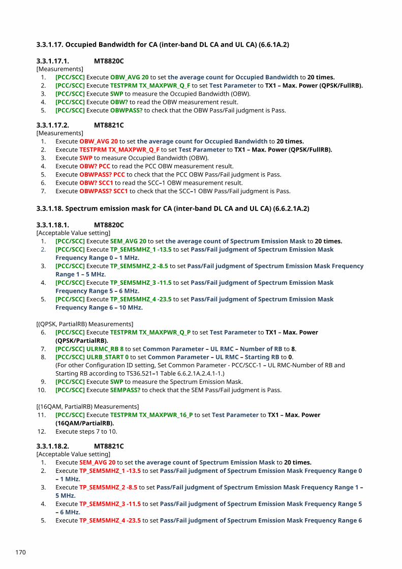
3.3.1.17. Occupied Bandwidth for CA (inter-band DL CA and UL CA) (6.6.1A.2) 3.3.1.17.1. MT8820C [Measurements]
1. [PCC/SCC] Execute OBW_AVG 20 to set the average count for Occupied Bandwidth to 20 times. 2. [PCC/SCC] Execute TESTPRM TX_MAXPWR_Q_F to set Test Parameter to TX1 – Max. Power (QPSK/FullRB). 3. [PCC/SCC] Execute SWP to measure the Occupied Bandwidth (OBW). 4. [PCC/SCC] Execute OBW? to read the OBW measurement result. 5. [PCC/SCC] Execute OBWPASS? to check that the OBW Pass/Fail judgment is Pass.
3.3.1.17.2. MT8821C [Measurements]
1. Execute OBW_AVG 20 to set the average count for Occupied Bandwidth to 20 times. 2. Execute TESTPRM TX_MAXPWR_Q_F to set Test Parameter to TX1 – Max. Power (QPSK/FullRB). 3. Execute SWP to measure Occupied Bandwidth (OBW). 4. Execute OBW? PCC to read the PCC OBW measurement result. 5. Execute OBWPASS? PCC to check that the PCC OBW Pass/Fail judgment is Pass. 6. Execute OBW? SCC1 to read the SCC–1 OBW measurement result. 7. Execute OBWPASS? SCC1 to check that the SCC–1 OBW Pass/Fail judgment is Pass.
3.3.1.18. Spectrum emission mask for CA (inter-band DL CA and UL CA) (6.6.2.1A.2) 3.3.1.18.1. MT8820C [Acceptable Value setting]
1. [PCC/SCC] Execute SEM_AVG 20 to set the average count of Spectrum Emission Mask to 20 times. 2. [PCC/SCC] Execute TP_SEM5MHZ_1 -13.5 to set Pass/Fail judgment of Spectrum Emission Mask
Frequency Range 0 – 1 MHz. 3. [PCC/SCC] Execute TP_SEM5MHZ_2 -8.5 to set Pass/Fail judgment of Spectrum Emission Mask Frequency
Range 1 – 5 MHz. 4. [PCC/SCC] Execute TP_SEM5MHZ_3 -11.5 to set Pass/Fail judgment of Spectrum Emission Mask
Frequency Range 5 – 6 MHz. 5. [PCC/SCC] Execute TP_SEM5MHZ_4 -23.5 to set Pass/Fail judgment of Spectrum Emission Mask
Frequency Range 6 – 10 MHz. [(QPSK, PartialRB) Measurements]
6. [PCC/SCC] Execute TESTPRM TX_MAXPWR_Q_P to set Test Parameter to TX1 – Max. Power (QPSK/PartialRB).
7. [PCC/SCC] ULRMC_RB 8 to set Common Parameter – UL RMC – Number of RB to 8. 8. [PCC/SCC] ULRB_START 0 to set Common Parameter – UL RMC – Starting RB to 0.
(For other Configuration ID setting, Set Common Parameter - PCC/SCC-1 – UL RMC-Number of RB and Starting RB according to TS36.521–1 Table 6.6.2.1A.2.4.1-1.)
9. [PCC/SCC] Execute SWP to measure the Spectrum Emission Mask. 10. [PCC/SCC] Execute SEMPASS? to check that the SEM Pass/Fail judgment is Pass. [(16QAM, PartialRB) Measurements] 11. [PCC/SCC] Execute TESTPRM TX_MAXPWR_16_P to set Test Parameter to TX1 – Max. Power
(16QAM/PartialRB). 12. Execute steps 7 to 10. 3.3.1.18.2. MT8821C [Acceptable Value setting]
1. Execute SEM_AVG 20 to set the average count of Spectrum Emission Mask to 20 times. 2. Execute TP_SEM5MHZ_1 -13.5 to set Pass/Fail judgment of Spectrum Emission Mask Frequency Range 0
– 1 MHz. 3. Execute TP_SEM5MHZ_2 -8.5 to set Pass/Fail judgment of Spectrum Emission Mask Frequency Range 1 –
5 MHz. 4. Execute TP_SEM5MHZ_3 -11.5 to set Pass/Fail judgment of Spectrum Emission Mask Frequency Range 5
– 6 MHz. 5. Execute TP_SEM5MHZ_4 -23.5 to set Pass/Fail judgment of Spectrum Emission Mask Frequency Range 6
170
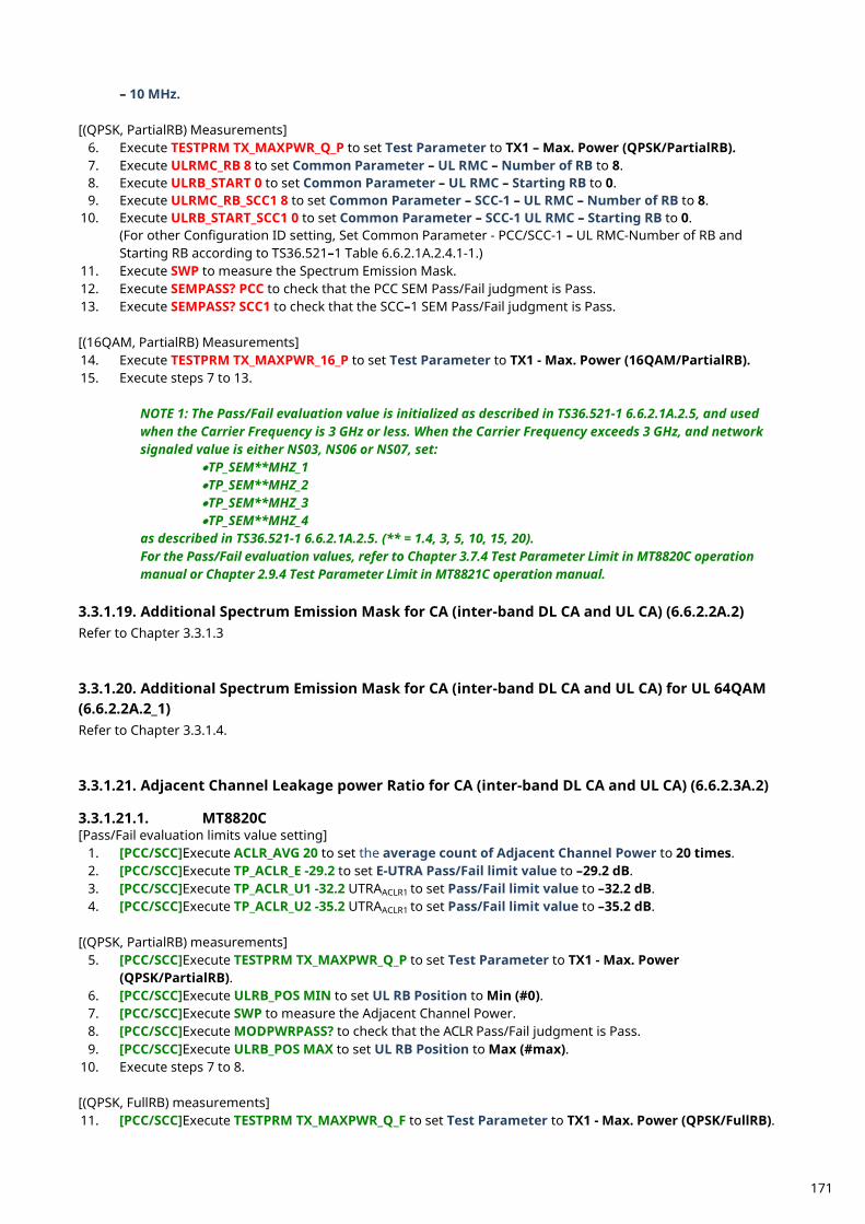
– 10 MHz. [(QPSK, PartialRB) Measurements]
6. Execute TESTPRM TX_MAXPWR_Q_P to set Test Parameter to TX1 – Max. Power (QPSK/PartialRB). 7. Execute ULRMC_RB 8 to set Common Parameter – UL RMC – Number of RB to 8. 8. Execute ULRB_START 0 to set Common Parameter – UL RMC – Starting RB to 0. 9. Execute ULRMC_RB_SCC1 8 to set Common Parameter – SCC-1 – UL RMC – Number of RB to 8.
10. Execute ULRB_START_SCC1 0 to set Common Parameter – SCC-1 UL RMC – Starting RB to 0. (For other Configuration ID setting, Set Common Parameter - PCC/SCC-1 – UL RMC-Number of RB and Starting RB according to TS36.521–1 Table 6.6.2.1A.2.4.1-1.)
11. Execute SWP to measure the Spectrum Emission Mask. 12. Execute SEMPASS? PCC to check that the PCC SEM Pass/Fail judgment is Pass. 13. Execute SEMPASS? SCC1 to check that the SCC–1 SEM Pass/Fail judgment is Pass. [(16QAM, PartialRB) Measurements] 14. Execute TESTPRM TX_MAXPWR_16_P to set Test Parameter to TX1 - Max. Power (16QAM/PartialRB). 15. Execute steps 7 to 13.
NOTE 1: The Pass/Fail evaluation value is initialized as described in TS36.521-1 6.6.2.1A.2.5, and used when the Carrier Frequency is 3 GHz or less. When the Carrier Frequency exceeds 3 GHz, and network signaled value is either NS03, NS06 or NS07, set:
•TP_SEM**MHZ_1 •TP_SEM**MHZ_2 •TP_SEM**MHZ_3 •TP_SEM**MHZ_4
as described in TS36.521-1 6.6.2.1A.2.5. (** = 1.4, 3, 5, 10, 15, 20). For the Pass/Fail evaluation values, refer to Chapter 3.7.4 Test Parameter Limit in MT8820C operation manual or Chapter 2.9.4 Test Parameter Limit in MT8821C operation manual.
3.3.1.19. Additional Spectrum Emission Mask for CA (inter-band DL CA and UL CA) (6.6.2.2A.2) Refer to Chapter 3.3.1.3 3.3.1.20. Additional Spectrum Emission Mask for CA (inter-band DL CA and UL CA) for UL 64QAM (6.6.2.2A.2_1) Refer to Chapter 3.3.1.4. 3.3.1.21. Adjacent Channel Leakage power Ratio for CA (inter-band DL CA and UL CA) (6.6.2.3A.2) 3.3.1.21.1. MT8820C [Pass/Fail evaluation limits value setting]
1. [PCC/SCC]Execute ACLR_AVG 20 to set the average count of Adjacent Channel Power to 20 times. 2. [PCC/SCC]Execute TP_ACLR_E -29.2 to set E-UTRA Pass/Fail limit value to –29.2 dB. 3. [PCC/SCC]Execute TP_ACLR_U1 -32.2 UTRAACLR1 to set Pass/Fail limit value to –32.2 dB. 4. [PCC/SCC]Execute TP_ACLR_U2 -35.2 UTRAACLR1 to set Pass/Fail limit value to –35.2 dB.
[(QPSK, PartialRB) measurements]
5. [PCC/SCC]Execute TESTPRM TX_MAXPWR_Q_P to set Test Parameter to TX1 - Max. Power (QPSK/PartialRB).
6. [PCC/SCC]Execute ULRB_POS MIN to set UL RB Position to Min (#0). 7. [PCC/SCC]Execute SWP to measure the Adjacent Channel Power. 8. [PCC/SCC]Execute MODPWRPASS? to check that the ACLR Pass/Fail judgment is Pass. 9. [PCC/SCC]Execute ULRB_POS MAX to set UL RB Position to Max (#max).
10. Execute steps 7 to 8. [(QPSK, FullRB) measurements] 11. [PCC/SCC]Execute TESTPRM TX_MAXPWR_Q_F to set Test Parameter to TX1 - Max. Power (QPSK/FullRB).
171
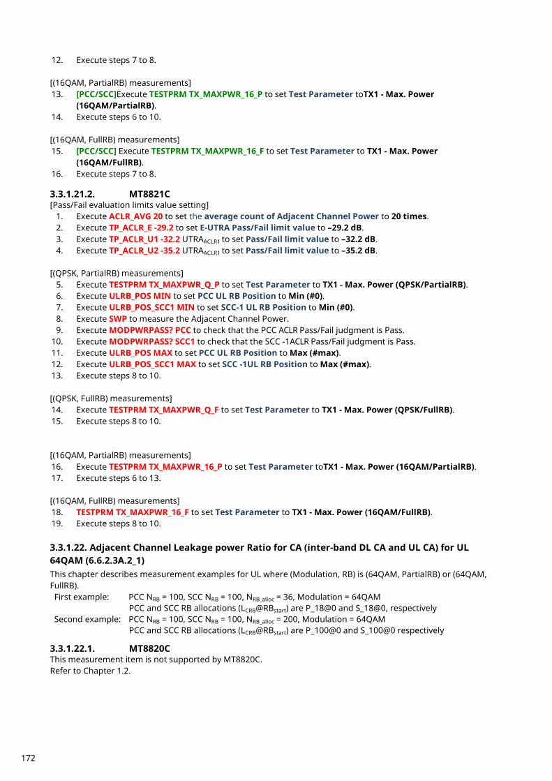
12. Execute steps 7 to 8. [(16QAM, PartialRB) measurements] 13. [PCC/SCC]Execute TESTPRM TX_MAXPWR_16_P to set Test Parameter toTX1 - Max. Power
(16QAM/PartialRB). 14. Execute steps 6 to 10. [(16QAM, FullRB) measurements] 15. [PCC/SCC] Execute TESTPRM TX_MAXPWR_16_F to set Test Parameter to TX1 - Max. Power
(16QAM/FullRB). 16. Execute steps 7 to 8. 3.3.1.21.2. MT8821C [Pass/Fail evaluation limits value setting]
1. Execute ACLR_AVG 20 to set the average count of Adjacent Channel Power to 20 times. 2. Execute TP_ACLR_E -29.2 to set E-UTRA Pass/Fail limit value to –29.2 dB. 3. Execute TP_ACLR_U1 -32.2 UTRAACLR1 to set Pass/Fail limit value to –32.2 dB. 4. Execute TP_ACLR_U2 -35.2 UTRAACLR1 to set Pass/Fail limit value to –35.2 dB.
[(QPSK, PartialRB) measurements]
5. Execute TESTPRM TX_MAXPWR_Q_P to set Test Parameter to TX1 - Max. Power (QPSK/PartialRB). 6. Execute ULRB_POS MIN to set PCC UL RB Position to Min (#0). 7. Execute ULRB_POS_SCC1 MIN to set SCC-1 UL RB Position to Min (#0). 8. Execute SWP to measure the Adjacent Channel Power. 9. Execute MODPWRPASS? PCC to check that the PCC ACLR Pass/Fail judgment is Pass.
10. Execute MODPWRPASS? SCC1 to check that the SCC -1ACLR Pass/Fail judgment is Pass. 11. Execute ULRB_POS MAX to set PCC UL RB Position to Max (#max). 12. Execute ULRB_POS_SCC1 MAX to set SCC -1UL RB Position to Max (#max). 13. Execute steps 8 to 10. [(QPSK, FullRB) measurements] 14. Execute TESTPRM TX_MAXPWR_Q_F to set Test Parameter to TX1 - Max. Power (QPSK/FullRB). 15. Execute steps 8 to 10. [(16QAM, PartialRB) measurements] 16. Execute TESTPRM TX_MAXPWR_16_P to set Test Parameter toTX1 - Max. Power (16QAM/PartialRB). 17. Execute steps 6 to 13. [(16QAM, FullRB) measurements] 18. TESTPRM TX_MAXPWR_16_F to set Test Parameter to TX1 - Max. Power (16QAM/FullRB). 19. Execute steps 8 to 10. 3.3.1.22. Adjacent Channel Leakage power Ratio for CA (inter-band DL CA and UL CA) for UL 64QAM (6.6.2.3A.2_1) This chapter describes measurement examples for UL where (Modulation, RB) is (64QAM, PartialRB) or (64QAM, FullRB). First example: PCC NRB = 100, SCC NRB = 100, NRB_alloc = 36, Modulation = 64QAM
PCC and SCC RB allocations (LCRB@RBstart) are P_18@0 and S_18@0, respectively Second example: PCC NRB = 100, SCC NRB = 100, NRB_alloc = 200, Modulation = 64QAM
PCC and SCC RB allocations (LCRB@RBstart) are P_100@0 and S_100@0 respectively 3.3.1.22.1. MT8820C This measurement item is not supported by MT8820C. Refer to Chapter 1.2.
172
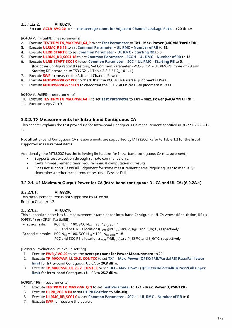
3.3.1.22.2. MT8821C 1. Execute ACLR_AVG 20 to set the average count for Adjacent Channel Leakage Ratio to 20 times. [(64QAM, PartialRB) measurements] 2. Execute TESTPRM TX_MAXPWR_64_P to set Test Parameter to TX1 - Max. Power (64QAM/PartialRB). 3. Execute ULRMC_RB 18 to set Common Parameter – UL RMC – Number of RB to 18. 4. Execute ULRB_START 0 to set Common Parameter – UL RMC – Starting RB to 0. 5. Execute ULRMC_RB_SCC1 18 to set Common Parameter – SCC-1 – UL RMC – Number of RB to 18. 6. Execute ULRB_START_SCC1 0 to set Common Parameter – SCC-1 UL RMC – Starting RB to 0.
(For other Configuration ID setting, Set Common Parameter - PCC/SCC-1 – UL RMC-Number of RB and Starting RB according to TS36.521–1 Table 6.6.2.3A.2_1.4.1-1.)
7. Execute SWP to measure the Adjacent Channel Power. 8. Execute MODPWRPASS? PCC to check that the PCC ACLR Pass/Fail judgment is Pass. 9. Execute MODPWRPASS? SCC1 to check that the SCC -1ACLR Pass/Fail judgment is Pass. [(64QAM, FullRB) measurements] 10. Execute TESTPRM TX_MAXPWR_64_F to set Test Parameter to TX1 – Max. Power (64QAM/FullRB). 11. Execute steps 7 to 9.
TX Measurements for Intra-band Contiguous CA 3.3.2.This chapter explains the test procedure for Intra–band Contiguous CA measurement specified in 3GPP TS 36.521–1. Not all Intra–band Contiguous CA measurements are supported by MT8820C. Refer to Table 1.2 for the list of supported measurement items. Additionally, the MT8820C has the following limitations for Intra–band contiguous CA measurement. Supports test execution through remote commands only. Certain measurement items require manual computation of results. Does not support Pass/Fail judgement for some measurement items, requiring user to manually
determine whether measurement results is Pass or Fail. 3.3.2.1. UE Maximum Output Power for CA (intra-band contiguous DL CA and UL CA) (6.2.2A.1) 3.3.2.1.1. MT8820C This measurement item is not supported by MT8820C. Refer to Chapter 1.2. 3.3.2.1.2. MT8821C This subsection describes UL measurement examples for Intra-band Contiguous UL CA where (Modulation, RB) is (QPSK, 1) or (QPSK, PartialRB) First example: PCC NRB = 100, SCC NRB = 25, NRB_alloc = 1
PCC and SCC RB allocations(LCRB@RBstart) are P_1@0 and S_0@0, respectively Second example: PCC NRB = 100, SCC NRB = 100, NRB_alloc = 18
PCC and SCC RB allocations(LCRB@RBstart) are P_18@0 and S_0@0, respectively [Pass/Fail evaluation limit value setting]
1. Execute PWR_AVG 20 to set the average count for Power Measurement to 20 2. Execute TP_MAXPWR_LL 20.3, CONTCC to set TX1 – Max. Power (QPSK/1RB/PartialRB) Pass/Fail lower
limit for Intra–band Contiguous UL CA to 20.3 dBm. 3. Execute TP_MAXPWR_UL 25.7, CONTCC to set TX1 – Max. Power (QPSK/1RB/PartialRB) Pass/Fail upper
limit for Intra–band Contiguous UL CA to 25.7 dBm. [(QPSK, 1RB) measurements]
4. Execute TESTPRM TX_MAXPWR_Q_1 to set Test Parameter to TX1 – Max. Power (QPSK/1RB). 5. Execute ULRB_POS MIN to set UL RB Position to Min(#0). 6. Execute ULRMC_RB_SCC1 0 to set Common Parameter – SCC-1 – UL RMC – Number of RB to 0. 7. Execute SWP to measure the power.
173
8. Execute POWER? AVG to read the TX power measurement result. 9. Execute POWERPASS? to check that the TX power measurement Pass/Fail judgment is Pass.
[(QPSK, PartialRB) measurements] 10. Execute TESTPRM TX_MAXPWR_Q_P to set Test Parameter to TX1 – Max. Power (QPSK/PartialRB). 11. Execute step 5 to 9.
NOTE 1: The tolerance (lower limit) can be relaxed by 1.5dB for transmission bandwidths confined within FUL_low and FUL_low + 4 MHz or FUL_high – 4 MHz and FUL_high.
NOTE 2: Pass/Fail judgment value varies depending on the CA Configuration.
The following judgment values are set in accordance with TS36.521–1 Table 6.2.2A.1.5–1. •TP_MAXPWR_LL •TP_MAXPWR_UL
For the Pass/Fail evaluation values, refer to Chapter 3.7.4 Test Parameter Limit in MT8820C operation manual or Chapter 2.9.4 Test Parameter Limit in MT8821C operation manual.
3.3.2.2. Maximum Power Reduction (MPR) for CA (intra-band contiguous DL CA and UL CA) (6.2.3A.1) 3.3.2.2.1. MT8820C This measurement item is not supported by MT8820C. Refer to Chapter 1.2. 3.3.2.2.2. MT8821C This chapter describes UL measurement examples for Intra–band contiguous UL CA measurement where (Modulation, RB) is (QPSK, FullRB), (16QAM, PartialRB), or (16QAM, FullRB). First example: PCC NRB = 100, SCC NRB = 25, NRB_alloc = 125, Modulation = QPSK
PCC and SCC RB allocations (LCRB@RBstart) are P_100@0 and S_25@0, respectively Second example: PCC NRB = 100, SCC NRB = 100, NRB_alloc = 18, Modulation = 16QAM
PCC and SCC RB allocations (LCRB@RBstart) are P_18@0 and S_0@0, respectively Third example: PCC NRB = 100, SCC NRB = 100, NRB_alloc = 200, Modulation = 16QAM
PCC and SCC RB allocations (LCRB@RBstart) are P_100@0 and S_100@0, respectively [Pass/Fail evaluation limits value setting]
1. Execute PWR_AVG 20 to set the average count of Power measurement to 20 times. 2. Execute TP_MPR1_LL 18.3, CONTCC to set TX1 – Max. Power (QPSK/FullRB) Pass/Fail lower limit for Intra–
band Contiguous UL CA to 18.3 dBm. 3. Execute TP_MPR1_UL 25.7, CONTCC to set TX1 – Max. Power (QPSK/FullRB) Pass/Fail upper limit for
Intra–band Contiguous UL CA to 25.7 dBm. 4. Execute TP_MPR2_LL 19.3, CONTCC to set TX1 – Max. Power (16QAM/PartialRB) Pass/Fail lower limit for
Intra–band Contiguous UL CA to 19.3 dBm. 5. Execute TP_MPR2_UL 25.7, CONTCC to set TX1 – Max. Power (16QAM/PartialRB) Pass/Fail upper limit for
Intra–band Contiguous UL CA to 25.7 dBm. 6. Execute TP_MPR3_LL 16.8, CONTCC to set TX1 – Max. Power (16QAM/FullRB) Pass/Fail lower limit for
Intra–band Contiguous UL CA to 16.8 dBm. 7. Execute TP_MPR3_UL 25.7, CONTCC to set TX1 - Max. Power (16QAM/FullRB) Pass/Fail upper limit for
Intra–band Contiguous UL CA to 25.7 dBm. [(QPSK, FullRB) measurements]
8. Execute TESTPRM TX_MAXPWR_Q_F to set Test Parameter to TX1 – Max. Power (QPSK/FullRB). 9. Execute SWP to measure the power.
10. Execute POWER? AVG to read the TX power measurement result. 11. Execute POWERPASS? to check that the TX power measurement Pass/Fail judgment is Pass. [(16QAM, PartialRB) measurements] 12. Execute TESTPRM TX_MAXPWR_16_P to set Test Parameter to TX1 – Max. Power (16QAM/PartialRB). 13. Execute ULRMC_RB 18 to set Common Parameter – UL RMC – Number of RB to 18.
174
14. Execute ULRMC_RB_SCC1 0 to set Common Parameter – SCC–1 – UL RMC – Number of RB to 0. 15. Execute steps 9 to 11. [(16QAM, FullRB ) measurements] 16. Execute TESTPRM TX_MAXPWR_16_F to set Test Parameter to TX1 – Max. Power (16QAM/FullRB). 17. Execute steps 9 to 11.
NOTE 1: The tolerance for MPR measurement differs depending on the Configuration ID at TS36.521–1 Table 6.2.3A.1.5-1 or 6.2.3A.1.5-1.
NOTE 2: Pass/Fail judgment value varies depending on the Configuration ID.
The following Pass/Fail judgment values are set accord ance with TS36.521–1 Table 6.2.3A.1.5–1 or 6.2.3A.1.5-2.
•TP_MPR1_LL •TP_MPR1_UL •TP_MPR2_LL •TP_MPR2_UL •TP_MPR3_LL •TP_MPR3_UL
For the Pass/Fail evaluation values, refer to Chapter 3.7.4 Test Parameter Limit in MT8820C operation manual or Chapter 2.9.4 Test Parameter Limit in MT8821C operation manual.
3.3.2.3. Maximum Power Reduction (MPR) for CA (intra-band contiguous DL CA and UL CA) for UL 64QAM (6.2.3A.1_1) 3.3.2.3.1. MT8820C This measurement item is not supported by MT8820C. Refer to Chapter 1.2. 3.3.2.3.2. MT8821C This chapter describes UL measurement examples for Intra–band contiguous UL CA measurement where (Modulation, RB) is (64QAM, PartialRB), or (64QAM, FullRB). First example: PCC NRB = 100, SCC NRB = 25, NRB_alloc = 8, Modulation = 64QAM
PCC and SCC RB allocations (LCRB@RBstart) are P_8@0 and S_0@0, respectively Second example: PCC NRB = 100, SCC NRB = 100, NRB_alloc = 200, Modulation = 64QAM
PCC and SCC RB allocations (LCRB@RBstart) are P_100@0 and S_100@0, respectively [Pass/Fail evaluation limits value setting]
1. Execute PWR_AVG 20 to set the average count of Power measurement to 20 times. 2. Execute TP_MPR4_LL 18.3, CONTCC to set TX1 – Max. Power (64QAM/PartialRB) Pass/Fail lower limit for
Intra–band Contiguous UL CA to 18.3 dBm. 3. Execute TP_MPR4_UL 25.7, CONTCC to set TX1 – Max. Power (64QAM/PartialRB) Pass/Fail upper limit for
Intra–band Contiguous UL CA to 25.7 dBm. 4. Execute TP_MPR5_LL 16.8, CONTCC to set TX1 – Max. Power (64QAM/FullRB) Pass/Fail lower limit for
Intra–band Contiguous UL CA to 16.8 dBm. 5. Execute TP_MPR5_UL 25.7, CONTCC to set TX1 - Max. Power (64QAM/FullRB) Pass/Fail upper limit for
Intra–band Contiguous UL CA to 25.7 dBm. [(64QAM, PartialRB) measurements]
6. Execute TESTPRM TX_MAXPWR_64_P to set Test Parameter to TX1 – Max. Power (64QAM/PartialRB). 7. Execute ULRMC_RB 8 to set Common Parameter – UL RMC – Number of RB to 8. 8. Execute ULRMC_RB_SCC1 0 to set Common Parameter – SCC–1 – UL RMC – Number of RB to 0. 9. Execute SWP to measure the power.
10. Execute POWER? AVG to read the TX power measurement result. 11. Execute POWERPASS? to check that the TX power measurement Pass/Fail judgment is Pass. [(64QAM, FullRB) measurements] 12. Execute TESTPRM TX_MAXPWR_64_F to set Test Parameter to TX1 – Max. Power (64QAM/FullRB). 13. Execute steps 9 to 11.
175
NOTE 1: Pass/Fail judgment value varies depending on the Configuration ID. The following Pass/Fail judgment values are set accordance with TS36.521–1 Table 6.2.3A.1_1.5–1 or 6.2.3A.1_1.5-2.
•TP_MPR4_LL •TP_MPR4_UL •TP_MPR5_LL •TP_MPR5_UL
For the Pass/Fail evaluation values, refer to Chapter 3.7.4 Test Parameter Limit in MT8820C operation manual or Chapter 2.9.4 Test Parameter Limit in MT8821C operation manual.
3.3.2.4. Additional Maximum Power Reduction (A-MPR) for CA (intra-band contiguous DL CA and UL CA) (6.2.4A.1) 3.3.2.4.1. MT8820C This measurement item is not supported by MT8820C. Refer to Chapter 1.2. 3.3.2.4.2. MT8821C This chapter describes UL measurement examples for Intra–band contiguous UL CA measurement where (Modulation, RB) is (QPSK, PartialRB), (QPSK, FullRB), or (16QAM, PartialRB) and Test Frequency is Mid range. First example: additionalSpectrumEmission is NS_01
PCC NRB = 75, SCC NRB = 75, NRB_alloc = 1, Modulation = QPSK PCC and SCC RB allocations (LCRB@RBstart) are P_1@0 and S_0@0, respectively
Second example: additionalSpectrumEmission is NS_04, PCC NRB = 100, SCC NRB = 50, NRB_alloc = 18, Modulation = 16QAM PCC and SCC RB allocations (LCRB@RBstart) are P_0@0 and S_18@0, respectively
1. Execute PWR_AVG 20 to set to measure Power average count of Power Measurement to 20 times. 2. Execute SEM_AVG 20 to set to measure Power average count of Spectrum Emission Mask to 20 times. 3. Execute SIB2_NS NS_01 set to Call Processing Parameter – additionalSpectrumEmission to NS_01. 4. Execute NS_SCC1 NS_01 set to Call Processing Parameter – additionalSpectrumEmissionSCell to NS_01. 5. Execute TESTPRM TX_MAXPWR_Q_F to set Test Parameter to TX1 – Max. Power (QPSK/FullRB). 6. Execute ALLMEASITEMS_OFF to set all fundamental measurement items to OFF. 7. Execute PWR_MEAS ON to set Power Measurement to ON. 8. Execute SEM_MEAS ON to set Spectrum Emission Mask Measurement to ON.
[(QPSK, PartialRB/FullRB) measurements]
9. Execute ULRMC_RB 18 to set Common Parameter – UL RMC – Number of RB to 18. 10. Execute ULRB_START 0 to set Common Parameter – UL RMC – Starting RB to 0. 11. Execute ULRMC_RB_SCC1 0 to set Common Parameter – SCC-1 – UL RMC – Number of RB to 0. 12. Execute ULRB_START_SCC1 0 to set Common Parameter – SCC-1 UL RMC – Starting RB to 0. 13. Execute TP_MPR1_UL 25.7, CONTCC to set TX Power measurement Pass/Fail upper limit to 25.7 dBm. 14. Execute TP_MPR1_LL 5.3, CONTCC to set TX Power measurement Pass/Fail lower limit 5.3 dBm. 15. Execute SWP to measure the power. 16. Execute POWER? AVG to read the TX Power measurement result. 17. Execute POWERPASS? to check that the TX Power Pass/Fail judgment is Pass. 18. Execute SEMPASS? to check that the SEM Pass/Fail judgment is Pass. [(16QAM, PartialRB) measurements] 19. Execute SIB2_NS NS_04 set to Call Processing Parameter – additionalSpectrumEmission to NS_04. 20. Execute TESTPRM TX_MAXPWR_16_P to set Test Parameter toTX1 – Max. Power (16QAM/PartialRB). 21. Execute ULRMC_RB 0 to set Common Parameter – UL RMC – Number of RB to 0. 22. Execute ULRMC_RB_SCC1 15 to set Common Parameter – SCC-1 – UL RMC - Number of RB to 15. 23. Execute ULRB_START_SCC1 0 to set Common Parameter – SCC-1 – UL RMC - Starting RB to 0. 24. Execute TP_MPR2_UL 25.7, CONTCC to set TX Power measurement Pass/Fail upper limit to 25.7 dBm. 25. Execute TP_MPR2_LL 20.3, CONTCC to set TX Power measurement Pass/Fail lower limit to 20.3 dBm. 26. Execute steps 15 to 18. NOTE 1: The tolerance for A–MPR measurement differs depending on the Configuration ID in TS36.521–1 Table
6.2.4A.1.5–1 through 6.
176
The Band 1 determination value defined at TS36.521–1 is set as the Pass/Fail judgment default value. Therefore, re–input is required after the Configuration ID for:
•TP_MPR1_LL •TP_MPR1_UL
For the Pass/Fail evaluation values, refer to Chapter 3.7.4 Test Parameter Limit in MT8820C operation manual or Chapter 2.9.4 Test Parameter Limit in MT8821C operation manual.
3.3.2.5. Additional Maximum Power Reduction (A-MPR) for CA (intra-band contiguous DL CA and UL CA) for 64QAM (6.2.4A.1_1) 3.3.2.5.1. MT8820C This measurement item is not supported by MT8820C. Refer to Chapter 1.2. 3.3.2.5.2. MT8821C This chapter describes UL measurement examples for Intra–band contiguous UL CA measurement where additionalSpectrumEmission is NS_01, (Modulation, RB) is (64QAM, PartialRB) or (64QAM, FullRB) and Test Frequency is Mid range. First example: additionalSpectrumEmission is NS_01
PCC NRB = 75, SCC NRB = 75, NRB_alloc = 1, Modulation = 64QAM PCC and SCC RB allocations (LCRB@RBstart) are P_1@0 and S_0@0, respectively
Second example: additionalSpectrumEmission is NS_01, PCC NRB = 75, SCC NRB = 75, NRB_alloc = 150, Modulation = 64QAM PCC and SCC RB allocations (LCRB@RBstart) are P_75@0 and S_75@0, respectively
1. Execute PWR_AVG 20 to set to measure Power average count of Power Measurement to 20 times. 2. Execute SEM_AVG 20 to set to measure Power average count of Spectrum Emission Mask to 20 times. 3. Execute SIB2_NS NS_01 set to Call Processing Parameter – additionalSpectrumEmission to NS_01. 4. Execute NS_SCC1 NS_01 set to Call Processing Parameter – additionalSpectrumEmissionSCell to NS_01. 5. Execute TESTPRM TX_MAXPWR_64_P to set Test Parameter to TX1 – Max. Power (64QAM/PartialRB). 6. Execute ALLMEASITEMS_OFF to set all fundamental measurement items to OFF. 7. Execute PWR_MEAS ON to set Power Measurement to ON. 8. Execute SEM_MEAS ON to set Spectrum Emission Mask Measurement to ON.
[(64QAM, PartialRB) measurements]
9. Execute ULRMC_RB 1 to set Common Parameter – UL RMC – Number of RB to 1. 10. Execute ULRB_START 0 to set Common Parameter – UL RMC – Starting RB to 0. 11. Execute ULRMC_RB_SCC1 0 to set Common Parameter – SCC-1 – UL RMC – Number of RB to 0. 12. Execute ULRB_START_SCC1 0 to set Common Parameter – SCC-1 UL RMC – Starting RB to 0. 13. Execute TP_MPR4_UL 25.7, CONTCC to set TX Power measurement Pass/Fail upper limit to 25.7 dBm. 14. Execute TP_MPR4_LL 5.3, CONTCC to set TX Power measurement Pass/Fail lower limit 5.3 dBm. 15. Execute SWP to measure the power. 16. Execute POWER? AVG to read the TX Power measurement result. 17. Execute POWERPASS? to check that the TX Power Pass/Fail judgment is Pass. 18. Execute SEMPASS? to check that the SEM Pass/Fail judgment is Pass. [(64QAM, FullRB) measurements] 19. Execute ULRMC_RB 75 to set Common Parameter – UL RMC – Number of RB to 75. 20. Execute ULRMC_RB_SCC1 75 to set Common Parameter – SCC-1 – UL RMC - Number of RB to 75. 21. Execute TP_MPR2_UL 25.7, CONTCC to set TX Power measurement Pass/Fail upper limit to 25.7 dBm. 22. Execute TP_MPR2_LL 11.3, CONTCC to set TX Power measurement Pass/Fail lower limit to 11.3 dBm. 23. Execute steps 15 to 18. NOTE 1: The UL RB Position for PartialRB allocation differs depending on the additionalSpectrumEmission and
the Configuration ID. See TS36.521–1 Table 6. 2.4A.1_1.4-1 through 6.2.4A.1_1.4-8.
NOTE 2: Pass/Fail judgment value varies depending on Configuration ID.
The following Pass/Fail judgment values are set accordance with TS36.521–1 Table 6.2.4A.1_1.5–1 through 6.2.4A.1_1.5-6.
177
•TP_MPR4_LL •TP_MPR4_UL
For the Pass/Fail evaluation values, refer to Chapter 3.7.4 Test Parameter Limit in MT8820C operation manual or Chapter 2.9.4 Test Parameter Limit in MT8821C operation manual.
3.3.2.6. Configured UE transmitted Output Power for CA (intra-band contiguous DL CA and UL CA) (6.2.5A.1) 3.3.2.6.1. MT8820C This measurement item is not supported by MT8820C. Refer to Chapter 1.2. 3.3.2.6.2. MT8821C [Pass/Fail evaluation limits value setting]
1. Execute PWR_AVG 20 to set the average count of Power measurement to 20 times. 2. Execute TP_CONFPWR1_TOL 7.7,CONTCC to set TX2 – Configured UE transmitted Output Power (Test
Point 1) Pass/Fail Judgment for Contiguous CC. 3. Execute TP_CONFPWR2_TOL 6.7,CONTCC to set TX2 – Configured UE transmitted Output Power (Test
Point 2) Pass/Fail Judgment for Contiguous CC. 4. Execute TP_CONFPWR3_TOL 5.7,CONTCC to set TX2 – Configured UE transmitted Output Power (Test
Point 3) Pass/Fail Judgment for Contiguous CC. [Measurements]
5. Execute TESTPRM TX_CONF_PWR1 to set Test Parameter toTX2 – Configured Power (Test Point 1). 6. Execute ULRMC_RB_SCC1 0 to set Common Parameter – SCC-1 – UL RMC – Number of RB to 0. 7. Execute SWP to measure the power. 8. Execute POWER? AVG to read the TX Power measurement result. 9. Execute TESTPRM TX_CONF_PWR2 to set Test Parameter to TX2 – Configured Power (Test Point 2).
10. Execute steps 6 to 8. 11. Execute TESTPRM TX_CONF_PWR3 to set Test Parameter to TX2 – Configured Power (Test Point 3). 12. Execute 6 to 8.
NOTE 1: The tolerance (lower limit) can be relaxed by 1.5dB for transmission bandwidths confined within FUL_low and FUL_low + 4 MHz or FUL_high – 4 MHz and FUL_high.
NOTE 2: Pass/Fail judgment values vary depending on the Carrier Frequency f.
f – 3.0 GHz :pMax ±7.7 dBm (at Test Point 1)
: pMax ±6.7 dBm (at Test Point 2) : pMax ±5.7 dBm (at Test Point 3)
3.0 GHz < f ≤ 4.2 GHz : pMax ±8.0 dBm (at Test Point 1) : pMax ±7.0 dBm (at Test Point 2)
: pMax ±6.0 dBm (at Test Point 3)
178
3.3.2.7. Minimum Output Power for CA (intra-band contiguous DL CA and UL CA) (6.3.2A.1) 3.3.2.7.1. MT8820C This measurement item is not supported by MT8820C. Refer to Chapter 1.2. 3.3.2.7.2. MT8821C This subsection describes an example of intra–band measurement. [Pass/Fail evaluation limits value setting]
1. Execute PWR_AVG 20 to set the average count of Power measurement to 20 times. 2. Execute TP_MINPWR_UL -39.0, PCC to set TX1 – Min. Power Pass/Fail judgment for PCC. 3. Execute TP_MINPWR_UL -39.0, SCC1 to set TX1 – Min. Power Pass/Fail judgment for SCC-1.
[Measurements]
4. Execute TESTPRM TX_MINPWR to set Test Parameter to TX1 – Min. Power. 5. Execute SWP to measure the power. 6. Execute CHPWR? AVG, PCC to read the Channel Power measurement result for PCC. 7. Execute CHPWR? AVG, SCC1 to read the Channel Power measurement result for SCC–1. 8. Execute CHPWRPASS? PCC to check that the Channel Power measurement Pass/Fail judgment for PCC is Pass. 9. Execute CHPWRPASS? SCC-1 to check that the Channel Power measurement Pass/Fail judgment for SCC–1 is
Pass. 10. Execute CHPWRPASS? to check that the Channel Power measurement Pass/Fail judgment for all CCs is Pass.
NOTE 2: Pass/Fail judgment values differ depending on the Carrier Frequency f.
f ≤ 3.0GHz : ≤ –39 dBm (as the initial value) 3.0GHz < f ≤ 4.2GHz : ≤ –38.7 dBm
3.3.2.8. UE Transmit OFF power for CA (intra-band contiguous DL CA and UL CA) (6.3.3A.1) Refer to Chapter 3.3.2.7. 3.3.2.9. General ON/OFF time mask for CA (intra-band contiguous DL CA and UL CA) (6.3.4A.1.1) 3.3.2.9.1. MT8820C This measurement item is not supported by MT8820C. Refer to Chapter 1.2. 3.3.2.9.2. MT8821C This subsection describes an example of intra–band measurement. [Pass/Fail evaluation limits value setting]
1. Execute TP_OFFPWR_UL -48.5, PCC to set TX2 – General Time Mask Off Power Pass/Fail judgment for PCC. 2. Execute TP_TMASK_GEN_TOL 7.5, PCC to set TX2 – General Time Mask On Power Pass/Fail judgment for PCC. 3. Execute TP_OFFPWR_UL -48.5, SCC1 to set TX2 – General Time Mask Off Power Pass/Fail judgment for SCC1. 4. Execute TP_TMASK_GEN_TOL 7.5, SCC1 to set TX2 – General Time Mask On Power Pass/Fail judgment for SCC1.
[Measurements]
5. Execute TESTPRM TX_GEN_TMASK to set Test Parameter to TX2 – General Time Mask. 6. Execute PT_WDR ON to enable Power Template Wide Dynamic Range measurement. 7. Execute SWP to measure the Power Template.
The following procedure is for validating the PCC result. 8. Execute ONPWR? AVG, PCC to read the On Power measurement result for PCC. 9. Execute ONPWRPASS? PCC to check that the On Power measurement Pass/Fail judgment for PCC is Pass.
10. Execute OFFPWR_BEFORE? AVG, PCC to read the Off Power (Before) measurement result for PCC. 11. Execute OFFPWR_AFTER? AVG, PCC to read the Off Power (After) measurement result for PCC. 12. Execute OFFPWRPASS? PCC to check that the Off Power measurement Pass/Fail judgment for PCC is Pass.
The following procedure is for validating the SCC–1 result. 13. Execute ONPWR? AVG, SCC1 to read the On Power measurement result for SCC–1. 14. Execute ONPWRPASS? SCC1 to check that the On Power measurement Pass/Fail judgment for SCC–1 is Pass. 15. Execute OFFPWR_BEFORE? AVG, SCC1 to read the Off Power (Before) measurement result for SCC–1. 16. Execute OFFPWR_AFTER? AVG, SCC1 to read the Off Power (After) measurement result for SCC–1.
179
17. Execute OFFPWRPASS? SCC1 to check that the Off Power measurement Pass/Fail judgment for SCC–1 is Pass.
NOTE: Pass/Fail judgment values for Transmitted Off Power differ depending on the Carrier Frequency f. f ≤ 3.0 GHz: ≤–48.5 dBm (initial value) 3.0GHz < f ≤ 4.2 GHz: ≤–48.2 dBm
3.3.2.10. Power Control Absolute power tolerance for CA (intra-band contiguous DL CA and UL CA) (6.3.5A.1.1) 3.3.2.10.1. MT8820C This measurement item is not supported by MT8820C. Refer to Chapter 1.2. 3.3.2.10.2. MT8821C This subsection describes an example of intra–band measurement. [Pass/Fail evaluation limits value setting]
1. Execute TP_PCTABS_TOL 10.0, PCC to set TX3 – Absolute Power (Test Point1/2) Pass/Fail judgment for PCC. 2. Execute TP_PCTABS_TOL 10.0, SCC1 to set TX3 – Absolute Power (Test Point1/2) Pass/Fail judgment for
SCC–1. [Measurements]
3. Execute TESTPRM TX_PCTABS1 to set Test Parameter toTX3 – Absolute Power (Test Point1). 4. Execute SWP to measure Power Control Tolerance(Absolute Power). 5. Execute PCTPWR? PCC to read the Absolute Power (dBm) measurement result for PCC. 6. Execute PCTPWR? SCC1 to read the Absolute Power (dBm) measurement result for SCC-1. 7. Execute PCTPASS? PCC to check that the Absolute Power measurement Pass/Fail judgment for PCC is Pass. 8. Execute PCTPASS? SCC1 to check that the Absolute Power measurement Pass/Fail judgment for SCC-1 is
Pass. 9. Execute PCTPASS? to check that the Absolute Power measurement Pass/Fail judgment for all CCs is Pass. 10. Execute TESTPRM TX_PCTABS2 to set Test Parameter to TX3 - Absolute Power (Test Point2). 11. Execute steps 4 to 9.
NOTE: The Pass/Fail judgment value for Expected Measured Power differs depending on the Carrier
Frequency f.
f ≤ 3.0 GHz: ≤10.0 dBm (initial value) 3.0GHz < f ≤ 4.2 GHz: ≤10.4 dBm
180
3.3.2.11. Power Control Relative power tolerance for CA (intra-band contiguous DL CA and UL CA) (6.3.5A.2.1) 3.3.2.11.1. MT8820C This measurement item is not supported by MT8820C. Refer to Chapter 1.2. 3.3.2.11.2. MT8821C This subsection describes an example of intra–band measurement. [Pass/Fail evaluation limits value setting] 1. Execute TP_PCTREL_INC_LL -1.7, PCC to set TX3 – Relative Power (SCC power increase) Pass/Fail lower limit
for PCC. 2. Execute TP_PCTREL_INC_UL 1.8, PCC to set TX3 – Relative Power (SCC power increase) Pass/Fail upper limit
for PCC. 3. Execute TP_PCTREL_INC_E_LL -6.7, PCC to set TX3 – Relative Power (SCC power increase) lower limit of the
Exception points for PCC. 4. Execute TP_PCTREL_INC_E_UL 6.8, PCC to set TX3 – Relative Power (SCC power increase) upper limit of the
Exception points for PCC. 5. Execute TP_PCTREL_INC_LL 4.2, SCC1 to set TX3 – Relative Power (SCC power increase) Pass/Fail lower limit
for SCC-1. 6. Execute TP_PCTREL_INC_UL 13.7, SCC1 to set TX3 – Relative Power (SCC power increase) Pass/Fail upper
limit for SCC-1. 7. Execute TP_PCTREL_INC_E_LL 2.2, SCC1 to set TX3 – Relative Power (SCC power increase) lower limit of the
Exception points for SCC-1. 8. Execute TP_PCTREL_INC_E_UL 15.8, SCC1 to set TX3 – Relative Power (SCC power increase) upper limit of
the Exception points for SCC-1. 9. Execute TP_PCTREL_INC_ULPWR 1.0 (See NOTE 1). 10. Execute TP_PCTREL_INC_REFSET 2.0 (See NOTE 2). 11. Execute TP_PCTREL_DEC_LL -1.8, PCC to set TX3 – Relative Power (SCC power decrease) Pass/Fail lower limit
for PCC. 12. Execute TP_PCTREL_DEC_UL 1.7, PCC to set TX3 – Relative Power (SCC power decrease) Pass/Fail upper limit
for PCC. 13. Execute TP_PCTREL_DEC_E_LL -6.8, PCC to set TX3 – Relative Power (SCC power decrease) lower limit of the
Exception points for PCC. 14. Execute TP_PCTREL_DEC_E_UL 6.7, PCC to set TX3 – Relative Power (SCC power decrease) upper limit of the
Exception points for PCC. 15. Execute TP_PCTREL_DEC_LL -13.8, SCC1 to set TX3 – Relative Power (SCC power decrease) Pass/Fail lower
limit for SCC-1. 16. Execute TP_PCTREL_DEC_UL -4.2, SCC1 to set TX3 – Relative Power (SCC power decrease) Pass/Fail upper
limit for SCC-1. 17. Execute TP_PCTREL_DEC_E_LL -15.8, SCC1 to set TX3 – Relative Power (SCC power decrease) lower limit of
the Exception points for SCC-1. 18. Execute TP_PCTREL_DEC_E_UL -2.2, SCC1 to set TX3 – Relative Power (SCC power decrease) upper limit of
the Exception points for SCC-1. 19. Execute TP_PCTREL_DEC_ULPWR 1.0 (See NOTE 3). 20. Execute TP_PCTREL_DEC_REFSET 2.0 (See NOTE 4). 21. Execute TP_PCTREL_INCTOG_LL 4.3, PCC to set TX3 – Relative Power (PCC/SCC power increase) Pass/Fail
lower limit for PCC. 22. Execute TP_PCTREL_INCTOG_UL 13.8, PCC to set TX3 – Relative Power (PCC/SCC power increase) Pass/Fail
upper limit for PCC. 23. Execute TP_PCTREL_INCTOG_E_LL 2.3, PCC to set TX3 – Relative Power (PCC/SCC power increase) lower limit
of the Exception points for PCC. 24. Execute TP_PCTREL_INCTOG_E_UL 15.8, PCC to set TX3 – Relative Power (PCC/SCC power increase) upper
limit of the Exception points for PCC. 25. Execute TP_PCTREL_INCTOG_LL 4.3, SCC1 to set TX3 – Relative Power (PCC/SCC power increase) Pass/Fail
lower limit for SCC-1. 26. Execute TP_PCTREL_INCTOG_UL 13.8, SCC1 to set TX3 – Relative Power (PCC/SCC power increase) Pass/Fail
upper limit for SCC-1.
181
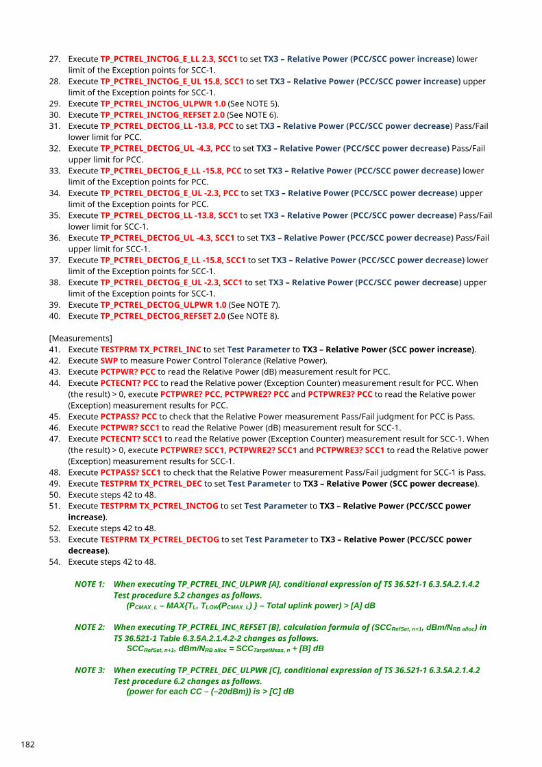
27. Execute TP_PCTREL_INCTOG_E_LL 2.3, SCC1 to set TX3 – Relative Power (PCC/SCC power increase) lower limit of the Exception points for SCC-1.
28. Execute TP_PCTREL_INCTOG_E_UL 15.8, SCC1 to set TX3 – Relative Power (PCC/SCC power increase) upper limit of the Exception points for SCC-1.
29. Execute TP_PCTREL_INCTOG_ULPWR 1.0 (See NOTE 5). 30. Execute TP_PCTREL_INCTOG_REFSET 2.0 (See NOTE 6). 31. Execute TP_PCTREL_DECTOG_LL -13.8, PCC to set TX3 – Relative Power (PCC/SCC power decrease) Pass/Fail
lower limit for PCC. 32. Execute TP_PCTREL_DECTOG_UL -4.3, PCC to set TX3 – Relative Power (PCC/SCC power decrease) Pass/Fail
upper limit for PCC. 33. Execute TP_PCTREL_DECTOG_E_LL -15.8, PCC to set TX3 – Relative Power (PCC/SCC power decrease) lower
limit of the Exception points for PCC. 34. Execute TP_PCTREL_DECTOG_E_UL -2.3, PCC to set TX3 – Relative Power (PCC/SCC power decrease) upper
limit of the Exception points for PCC. 35. Execute TP_PCTREL_DECTOG_LL -13.8, SCC1 to set TX3 – Relative Power (PCC/SCC power decrease) Pass/Fail
lower limit for SCC-1. 36. Execute TP_PCTREL_DECTOG_UL -4.3, SCC1 to set TX3 – Relative Power (PCC/SCC power decrease) Pass/Fail
upper limit for SCC-1. 37. Execute TP_PCTREL_DECTOG_E_LL -15.8, SCC1 to set TX3 – Relative Power (PCC/SCC power decrease) lower
limit of the Exception points for SCC-1. 38. Execute TP_PCTREL_DECTOG_E_UL -2.3, SCC1 to set TX3 – Relative Power (PCC/SCC power decrease) upper
limit of the Exception points for SCC-1. 39. Execute TP_PCTREL_DECTOG_ULPWR 1.0 (See NOTE 7). 40. Execute TP_PCTREL_DECTOG_REFSET 2.0 (See NOTE 8). [Measurements] 41. Execute TESTPRM TX_PCTREL_INC to set Test Parameter to TX3 – Relative Power (SCC power increase). 42. Execute SWP to measure Power Control Tolerance (Relative Power). 43. Execute PCTPWR? PCC to read the Relative Power (dB) measurement result for PCC. 44. Execute PCTECNT? PCC to read the Relative power (Exception Counter) measurement result for PCC. When
(the result) > 0, execute PCTPWRE? PCC, PCTPWRE2? PCC and PCTPWRE3? PCC to read the Relative power (Exception) measurement results for PCC.
45. Execute PCTPASS? PCC to check that the Relative Power measurement Pass/Fail judgment for PCC is Pass. 46. Execute PCTPWR? SCC1 to read the Relative Power (dB) measurement result for SCC-1. 47. Execute PCTECNT? SCC1 to read the Relative power (Exception Counter) measurement result for SCC-1. When
(the result) > 0, execute PCTPWRE? SCC1, PCTPWRE2? SCC1 and PCTPWRE3? SCC1 to read the Relative power (Exception) measurement results for SCC-1.
48. Execute PCTPASS? SCC1 to check that the Relative Power measurement Pass/Fail judgment for SCC-1 is Pass. 49. Execute TESTPRM TX_PCTREL_DEC to set Test Parameter to TX3 – Relative Power (SCC power decrease). 50. Execute steps 42 to 48. 51. Execute TESTPRM TX_PCTREL_INCTOG to set Test Parameter to TX3 – Relative Power (PCC/SCC power
increase). 52. Execute steps 42 to 48. 53. Execute TESTPRM TX_PCTREL_DECTOG to set Test Parameter to TX3 – Relative Power (PCC/SCC power
decrease). 54. Execute steps 42 to 48.
NOTE 1: When executing TP_PCTREL_INC_ULPWR [A], conditional expression of TS 36.521-1 6.3.5A.2.1.4.2 Test procedure 5.2 changes as follows.
(PCMAX_L – MAX{TL, TLOW(PCMAX_L) } – Total uplink power) > [A] dB
NOTE 2: When executing TP_PCTREL_INC_REFSET [B], calculation formula of (SCCRefSet, n+1, dBm/NRB alloc) in TS 36.521-1 Table 6.3.5A.2.1.4.2-2 changes as follows.
SCCRefSet, n+1, dBm/NRB alloc = SCCTargetMeas, n + [B] dB
NOTE 3: When executing TP_PCTREL_DEC_ULPWR [C], conditional expression of TS 36.521-1 6.3.5A.2.1.4.2 Test procedure 6.2 changes as follows.
(power for each CC – (–20dBm)) is > [C] dB
182
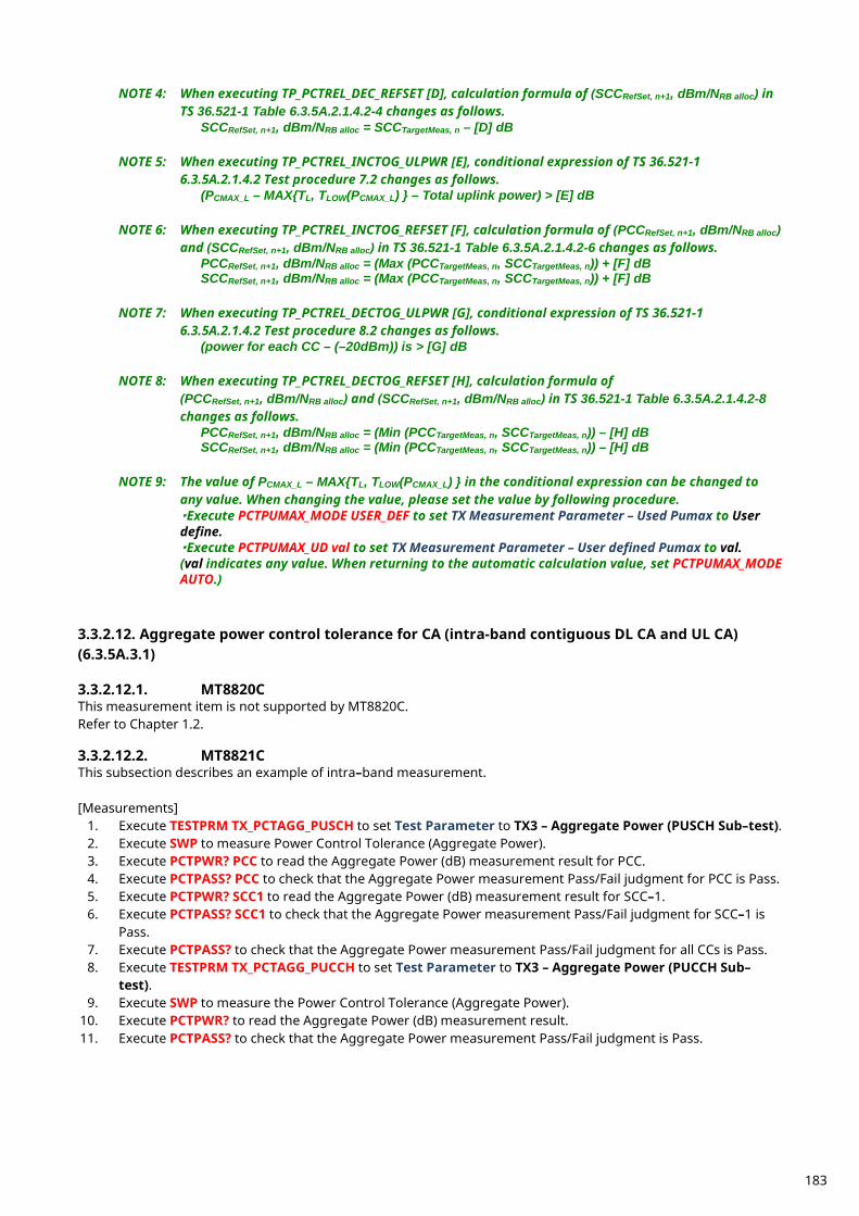
NOTE 4: When executing TP_PCTREL_DEC_REFSET [D], calculation formula of (SCCRefSet, n+1, dBm/NRB alloc) in TS 36.521-1 Table 6.3.5A.2.1.4.2-4 changes as follows.
SCCRefSet, n+1, dBm/NRB alloc = SCCTargetMeas, n – [D] dB
NOTE 5: When executing TP_PCTREL_INCTOG_ULPWR [E], conditional expression of TS 36.521-1 6.3.5A.2.1.4.2 Test procedure 7.2 changes as follows.
(PCMAX_L – MAX{TL, TLOW(PCMAX_L) } – Total uplink power) > [E] dB
NOTE 6: When executing TP_PCTREL_INCTOG_REFSET [F], calculation formula of (PCCRefSet, n+1, dBm/NRB alloc) and (SCCRefSet, n+1, dBm/NRB alloc) in TS 36.521-1 Table 6.3.5A.2.1.4.2-6 changes as follows.
PCCRefSet, n+1, dBm/NRB alloc = (Max (PCCTargetMeas, n, SCCTargetMeas, n)) + [F] dB SCCRefSet, n+1, dBm/NRB alloc = (Max (PCCTargetMeas, n, SCCTargetMeas, n)) + [F] dB
NOTE 7: When executing TP_PCTREL_DECTOG_ULPWR [G], conditional expression of TS 36.521-1
6.3.5A.2.1.4.2 Test procedure 8.2 changes as follows. (power for each CC – (–20dBm)) is > [G] dB
NOTE 8: When executing TP_PCTREL_DECTOG_REFSET [H], calculation formula of
(PCCRefSet, n+1, dBm/NRB alloc) and (SCCRefSet, n+1, dBm/NRB alloc) in TS 36.521-1 Table 6.3.5A.2.1.4.2-8 changes as follows.
PCCRefSet, n+1, dBm/NRB alloc = (Min (PCCTargetMeas, n, SCCTargetMeas, n)) – [H] dB SCCRefSet, n+1, dBm/NRB alloc = (Min (PCCTargetMeas, n, SCCTargetMeas, n)) – [H] dB
NOTE 9: The value of PCMAX_L – MAX{TL, TLOW(PCMAX_L) } in the conditional expression can be changed to
any value. When changing the value, please set the value by following procedure. ・Execute PCTPUMAX_MODE USER_DEF to set TX Measurement Parameter – Used Pumax to User define. ・Execute PCTPUMAX_UD val to set TX Measurement Parameter – User defined Pumax to val. (val indicates any value. When returning to the automatic calculation value, set PCTPUMAX_MODE AUTO.)
3.3.2.12. Aggregate power control tolerance for CA (intra-band contiguous DL CA and UL CA) (6.3.5A.3.1) 3.3.2.12.1. MT8820C This measurement item is not supported by MT8820C. Refer to Chapter 1.2. 3.3.2.12.2. MT8821C This subsection describes an example of intra–band measurement. [Measurements]
1. Execute TESTPRM TX_PCTAGG_PUSCH to set Test Parameter to TX3 – Aggregate Power (PUSCH Sub–test). 2. Execute SWP to measure Power Control Tolerance (Aggregate Power). 3. Execute PCTPWR? PCC to read the Aggregate Power (dB) measurement result for PCC. 4. Execute PCTPASS? PCC to check that the Aggregate Power measurement Pass/Fail judgment for PCC is Pass. 5. Execute PCTPWR? SCC1 to read the Aggregate Power (dB) measurement result for SCC–1. 6. Execute PCTPASS? SCC1 to check that the Aggregate Power measurement Pass/Fail judgment for SCC–1 is
Pass. 7. Execute PCTPASS? to check that the Aggregate Power measurement Pass/Fail judgment for all CCs is Pass. 8. Execute TESTPRM TX_PCTAGG_PUCCH to set Test Parameter to TX3 – Aggregate Power (PUCCH Sub–
test). 9. Execute SWP to measure the Power Control Tolerance (Aggregate Power).
10. Execute PCTPWR? to read the Aggregate Power (dB) measurement result. 11. Execute PCTPASS? to check that the Aggregate Power measurement Pass/Fail judgment is Pass.
183
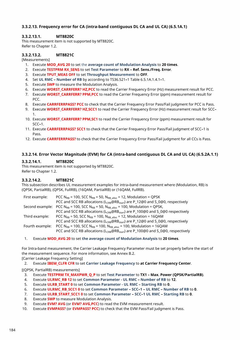
3.3.2.13. Frequency error for CA (intra-band contiguous DL CA and UL CA) (6.5.1A.1) 3.3.2.13.1. MT8820C This measurement item is not supported by MT8820C. Refer to Chapter 1.2. 3.3.2.13.2. MT8821C [Measurements]
1. Execute MOD_AVG 20 to set the average count of Modulation Analysis to 20 times. 2. Execute TESTPRM RX_SENS to set Test Parameter to RX – Ref. Sens./Freq. Error. 3. Execute TPUT_MEAS OFF to set Throughput Measurement to OFF. 4. Set UL RMC – Number of RB by according to TS36.521–1 Table 6.5.1A.1.4.1–1. 5. Execute SWP to measure the Modulation Analysis. 6. Execute WORST_CARRFERR? HZ,PCC to read the Carrier Frequency Error (Hz) measurement result for PCC. 7. Execute WORST_CARRFERR? PPM,PCC to read the Carrier Frequency Error (ppm) measurement result for
PCC. 8. Execute CARRFERRPASS? PCC to check that the Carrier Frequency Error Pass/Fail judgment for PCC is Pass. 9. Execute WORST_CARRFERR? HZ,SCC1 to read the Carrier Frequency Error (Hz) measurement result for SCC–
1. 10. Execute WORST_CARRFERR? PPM,SC1 to read the Carrier Frequency Error (ppm) measurement result for
SCC–1. 11. Execute CARRFERRPASS? SCC1 to check that the Carrier Frequency Error Pass/Fail judgment of SCC–1 is
Pass. 12. Execute CARRFERRPASS? to check that the Carrier Frequency Error Pass/Fail judgment for all CCs is Pass.
3.3.2.14. Error Vector Magnitude (EVM) for CA (intra-band contiguous DL CA and UL CA) (6.5.2A.1.1) 3.3.2.14.1. MT8820C This measurement item is not supported by MT8820C. Refer to Chapter 1.2. 3.3.2.14.2. MT8821C This subsection describes UL measurement examples for intra–band measurement where (Modulation, RB) is (QPSK, PartialRB), (QPSK, FullRB), (16QAM, PartialRB) or (16QAM, FullRB). First example: PCC NRB = 100, SCC NRB = 50, NRB_alloc = 12, Modulation = QPSK
PCC and SCC RB allocations (LCRB@RBstart) are P_12@0 and S_0@0, respectively Second example: PCC NRB = 100, SCC NRB = 50, NRB_alloc = 100, Modulation = QPSK,
PCC and SCC RB allocations (LCRB@RBstart) are P_100@0 and S_0@0 respectively Third example: PCC NRB = 50, SCC NRB = 100, NRB_alloc = 12, Modulation = 16QAM
PCC and SCC RB allocations (LCRB@RBstart) are P_12@0 and S_0@0, respectively Fourth example: PCC NRB = 100, SCC NRB = 100, NRB_alloc = 100, Modulation = 16QAM
PCC and SCC RB allocations (LCRB@RBstart) are P_100@0 and S_0@0, respectively
1. Execute MOD_AVG 20 to set the average count of Modulation Analysis to 20 times. For Intra-band measurement, the Carrier Leakage Frequency Parameter must be set properly before the start of the measurement sequence. For more information, see Annex B.2. [Carrier Leakage Frequency Setting]
2. Execute IBEM_CLFR CFR to set Carrier Leakage Frequency to at Carrier Frequency Center. [(QPSK, PartialRB) measurements]
3. Execute TESTPRM TX_MAXPWR_Q_P to set Test Parameter to TX1 – Max. Power (QPSK/PartialRB). 4. Execute ULRMC_RB 12 to set Common Parameter - UL RMC – Number of RB to 12. 5. Execute ULRB_START 0 to set Common Parameter - UL RMC – Starting RB to 0. 6. Execute ULRMC_RB_SCC1 0 to set Common Parameter – SCC–1 – UL RMC – Number of RB to 0. 7. Execute ULRB_START_SCC1 0 to set Common Parameter – SCC–1 UL RMC – Starting RB to 0. 8. Execute SWP to measure Modulation Analysis. 9. Execute EVM? AVG (or EVM? AVG,PCC) to read the EVM measurement result.
10. Execute EVMPASS? (or EVMPASS? PCC) to check that the EVM Pass/Fail judgment is Pass.
184
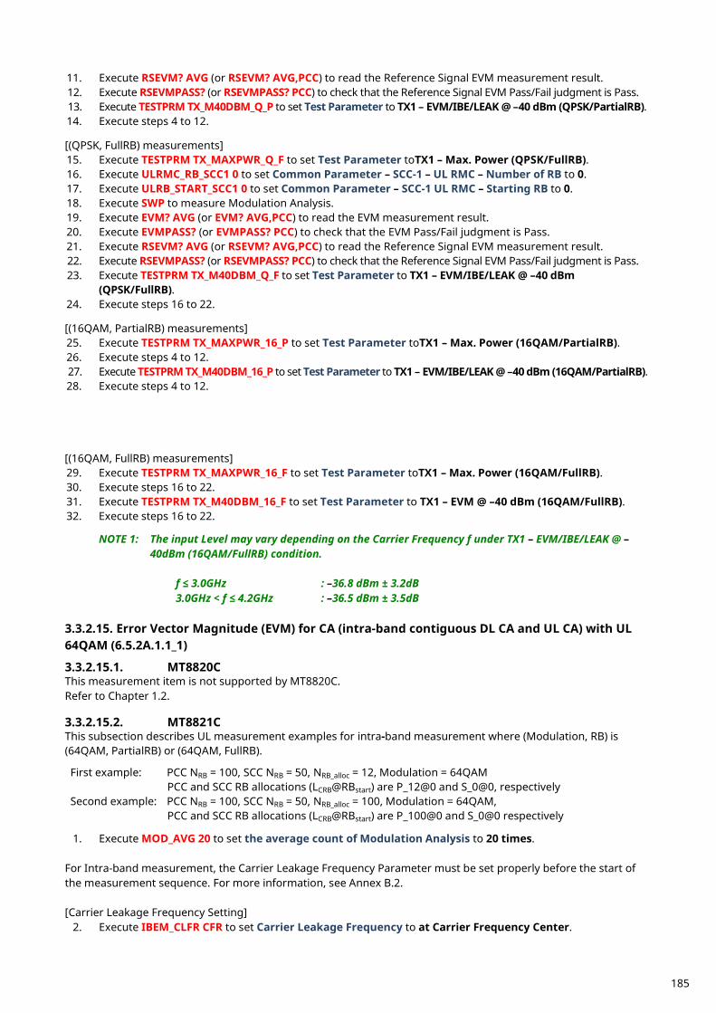
11. Execute RSEVM? AVG (or RSEVM? AVG,PCC) to read the Reference Signal EVM measurement result. 12. Execute RSEVMPASS? (or RSEVMPASS? PCC) to check that the Reference Signal EVM Pass/Fail judgment is Pass. 13. Execute TESTPRM TX_M40DBM_Q_P to set Test Parameter to TX1 – EVM/IBE/LEAK @ –40 dBm (QPSK/PartialRB). 14. Execute steps 4 to 12. [(QPSK, FullRB) measurements] 15. Execute TESTPRM TX_MAXPWR_Q_F to set Test Parameter toTX1 – Max. Power (QPSK/FullRB). 16. Execute ULRMC_RB_SCC1 0 to set Common Parameter – SCC-1 – UL RMC – Number of RB to 0. 17. Execute ULRB_START_SCC1 0 to set Common Parameter – SCC-1 UL RMC – Starting RB to 0. 18. Execute SWP to measure Modulation Analysis. 19. Execute EVM? AVG (or EVM? AVG,PCC) to read the EVM measurement result. 20. Execute EVMPASS? (or EVMPASS? PCC) to check that the EVM Pass/Fail judgment is Pass. 21. Execute RSEVM? AVG (or RSEVM? AVG,PCC) to read the Reference Signal EVM measurement result. 22. Execute RSEVMPASS? (or RSEVMPASS? PCC) to check that the Reference Signal EVM Pass/Fail judgment is Pass. 23. Execute TESTPRM TX_M40DBM_Q_F to set Test Parameter to TX1 – EVM/IBE/LEAK @ –40 dBm
(QPSK/FullRB). 24. Execute steps 16 to 22. [(16QAM, PartialRB) measurements] 25. Execute TESTPRM TX_MAXPWR_16_P to set Test Parameter toTX1 – Max. Power (16QAM/PartialRB). 26. Execute steps 4 to 12. 27. Execute TESTPRM TX_M40DBM_16_P to set Test Parameter to TX1 – EVM/IBE/LEAK @ –40 dBm (16QAM/PartialRB). 28. Execute steps 4 to 12. [(16QAM, FullRB) measurements] 29. Execute TESTPRM TX_MAXPWR_16_F to set Test Parameter toTX1 – Max. Power (16QAM/FullRB). 30. Execute steps 16 to 22. 31. Execute TESTPRM TX_M40DBM_16_F to set Test Parameter to TX1 – EVM @ –40 dBm (16QAM/FullRB). 32. Execute steps 16 to 22.
NOTE 1: The input Level may vary depending on the Carrier Frequency f under TX1 – EVM/IBE/LEAK @ –40dBm (16QAM/FullRB) condition.
f ≤ 3.0GHz : –36.8 dBm ± 3.2dB 3.0GHz < f ≤ 4.2GHz : –36.5 dBm ± 3.5dB
3.3.2.15. Error Vector Magnitude (EVM) for CA (intra-band contiguous DL CA and UL CA) with UL 64QAM (6.5.2A.1.1_1) 3.3.2.15.1. MT8820C This measurement item is not supported by MT8820C. Refer to Chapter 1.2. 3.3.2.15.2. MT8821C This subsection describes UL measurement examples for intra-band measurement where (Modulation, RB) is (64QAM, PartialRB) or (64QAM, FullRB). First example: PCC NRB = 100, SCC NRB = 50, NRB_alloc = 12, Modulation = 64QAM
PCC and SCC RB allocations (LCRB@RBstart) are P_12@0 and S_0@0, respectively Second example: PCC NRB = 100, SCC NRB = 50, NRB_alloc = 100, Modulation = 64QAM,
PCC and SCC RB allocations (LCRB@RBstart) are P_100@0 and S_0@0 respectively
1. Execute MOD_AVG 20 to set the average count of Modulation Analysis to 20 times. For Intra-band measurement, the Carrier Leakage Frequency Parameter must be set properly before the start of the measurement sequence. For more information, see Annex B.2. [Carrier Leakage Frequency Setting]
2. Execute IBEM_CLFR CFR to set Carrier Leakage Frequency to at Carrier Frequency Center.
185
[First example measurements] 3. Execute TESTPRM TX_MAXPWR_64_P to set Test Parameter to TX1 – Max. Power (64QAM/PartialRB). 4. Execute ULRMC_RB 12 to set Common Parameter - UL RMC – Number of RB to 12. 5. Execute ULRB_START 0 to set Common Parameter - UL RMC – Starting RB to 0. 6. Execute ULRMC_RB_SCC1 0 to set Common Parameter – SCC–1 – UL RMC – Number of RB to 0. 7. Execute ULRB_START_SCC1 0 to set Common Parameter – SCC–1 UL RMC – Starting RB to 0. 8. Execute SWP to measure Modulation Analysis. 9. Execute EVM? AVG (or EVM? AVG,PCC) to read the EVM measurement result.
10. Execute EVMPASS? (or EVMPASS? PCC) to check that the EVM Pass/Fail judgment is Pass. 11. Execute RSEVM? AVG (or RSEVM? AVG,PCC) to read the Reference Signal EVM measurement result. 12. Execute RSEVMPASS? (or RSEVMPASS? PCC) to check that the Reference Signal EVM Pass/Fail judgment is Pass. 13. Execute TESTPRM TX_M40DBM_64_P to set Test Parameter to TX1 – EVM/IBE/LEAK @ –40 dBm
(64QAM/PartialRB). 14. Execute steps 4 to 12. [Second example measurements] 15. Execute TESTPRM TX_MAXPWR_64_F to set Test Parameter toTX1 – Max. Power (64QAM/FullRB). 16. Execute ULRMC_RB_SCC1 0 to set Common Parameter – SCC-1 – UL RMC – Number of RB to 0. 17. Execute ULRB_START_SCC1 0 to set Common Parameter – SCC-1 UL RMC – Starting RB to 0. 18. Execute SWP to measure Modulation Analysis. 19. Execute EVM? AVG (or EVM? AVG,PCC) to read the EVM measurement result. 20. Execute EVMPASS? (or EVMPASS? PCC) to check that the EVM Pass/Fail judgment is Pass. 21. Execute RSEVM? AVG (or RSEVM? AVG,PCC) to read the Reference Signal EVM measurement result. 22. Execute RSEVMPASS? (or RSEVMPASS? PCC) to check that the Reference Signal EVM Pass/Fail judgment is Pass. 23. Execute TESTPRM TX_M40DBM_64_F to set Test Parameter to TX1 – EVM/IBE/LEAK @ –40 dBm
(64QAM/FullRB). 24. Execute steps 16 to 22.
NOTE 1: The input Level may vary depending on the Carrier Frequency f under TX1 – EVM/IBE/LEAK @ –40dBm (64QAM/FullRB) condition.
f ≤ 3.0GHz : –36.8 dBm ± 3.2dB 3.0GHz < f ≤ 4.2GHz : –36.5 dBm ± 3.5dB
3.3.2.16. Carrier leakage for CA (intra-band contiguous DL CA and UL CA) (6.5.2A.2.1) 3.3.2.16.1. MT8820C This measurement item is not supported by MT8820C. Refer to Chapter 1.2. 3.3.2.16.2. MT8821C This subsection describes an example of intra–band measurement. Example: PCC NRB = 100, SCC NRB = 50, NRB_alloc = 12, Modulation = QPSK
PCC and SCC RB allocations (LCRB@RBstart) are P_18@0 and S_0@0, respectively For Intra-band measurement, Carrier Leakage Frequency Parameter must be set properly before the start of the measurement sequence. For more information, see Annex B.2. [Carrier Leakage Frequency Setting]
1. Execute IBEM_CLFR CFR to set Carrier Leakage Frequency to at Carrier Frequency Center. [Measurements]
2. Execute MOD_AVG 20 to set the average count of Modulation Analysis to 20 times. 3. Execute TESTPRM TX_0DBM to set Test Parameter to TX1 – IBE/LEAK @ 0 dBm. 4. Execute ULRMC_RB_PCC 18 to set Common Parameter – PCC – UL RMC – Number of RB to 18.
(For other Configuration ID setting, set UL RMC – Number of RB and Starting RB according to TS36.521–1 Table 6.5.2A.2.1.4.1–1.)
5. Execute ULRMC_RB_SCC1 0 to set Common Parameter - SCC–1 – UL RMC – Number of RB to 0. 6. Execute SWP to measure the Modulation Analysis. 7. Execute CARRLEAK? MAX (or CARRLEAK? MAX,PCC) to read the Carrier Leakage measurement result. 8. Execute CARRLEAKPASS? (or CARRLEAKPASS? PCC) to check that the Carrier Leakage Pass/Fail judgment is
Pass.
186
9. Execute TESTPRM TX_M30DBM to set Test Parameter to TX1 – IBE/LEAK @ –30 dBm. 10. Execute steps 4 to 8. 11. Execute TESTPRM TX_M40DBM_Q_P to set Test Parameter toTX1 – EVM/IBE/LEAK @ –40 dBm
(QPSK/PartialRB). 12. Execute steps 4 to 8.
NOTE 1: The input level varies depending on the Carrier Frequency f under the TX1–IBE/LEAK @ 0dBm condition.
f ≤ 3.0 GHz: 3.2 dBm ±3.2 dB 3.0 GHz < f ≤ 4.2 GHz: 3.5 dBm ±3.5 dB
NOTE 2: The input level varies depending on the Carrier Frequency f under TX1–IBE/LEAK @ –30dBm
condition.
f ≤ 3.0 GHz: –26.8 dBm ±3.2 dB 3.0 GHz < f ≤ 4.2 GHz: –26.5 dBm ± 3.5 dB
NOTE 3: The input level varies depending on the Carrier Frequency f under the TX1–EVM/IBE/LEAK @ –
40dBm condition.
f ≤ 3.0 GHz: –36.8 dBm ±3.2dB 3.0GHz < f ≤ 4.2 GHz: –36.5 dBm ±3.5dB
3.3.2.17. In-band emissions for non allocated RB for CA (intra-band contiguous DL CA and UL CA) (6.5.2A.3.1) 3.3.2.17.1. MT8820C This measurement item is not supported by MT8820C. Refer to Chapter 1.2. 3.3.2.17.2. MT8821C This subsection describes an example of intra–band measurement. Example: PCC NRB = 100, SCC NRB = 50, NRB_alloc = 12, Modulation = QPSK
PCC and SCC RB allocations (LCRB@RBstart) are P_12@0 and S_0@0, respectively For Intra–band measurement, the Carrier Leakage Frequency Parameter must be set properly before the start of measurement sequence. For more information, see Annex B.2. [Carrier Leakage Frequency Setting]
1. Execute IBEM_CLFR CFR to set Carrier Leakage Frequency to at Carrier Frequency Center. [Pass/Fail evaluation limits value setting]
2. Execute MOD_AVG 20 to set the average count of Modulation Analysis to 20 times. 3. Execute TP_INBANDE_GEN_A -29.2 (or TP_INBANDE_GEN_A -29.2, PCC) to set General Pass/Fail judgment of
TX1 - IBE/LEAK @ 0/–30/–40 dBm for PCC. 4. Execute TP_INBANDE_GEN_B -24.2 (or TP_INBANDE_GEN_B -24.2, PCC) to set General Pass/Fail judgment of
TX1 - IBE/LEAK @ 0/–30/–40 dBm for PCC. 5. Execute TP_INBANDE_GEN_C -2.2 (or TP_INBANDE_GEN_C -2.2, PCC) to set General Pass/Fail judgment of
TX1 - IBE/LEAK @ 0/–30/–40 dBm for PCC. 6. Execute TP_INBANDE_GEN_D -56.2 (or TP_INBANDE_GEN_D -56.2, PCC) to set General Pass/Fail judgment of
TX1 - IBE/LEAK @ 0/–30/–40 dBm for PCC. 7. Execute TP_INBANDE_IMG –24.2 (or TP_INBANDE_IMG –24.2, PCC) to set General Pass/Fail judgment of TX1
- IBE/LEAK @ 0/–30/–40 dBm for PCC. 8. Execute TP_INBANDE_LEAK_0DBM –24.2 (or TP_INBANDE_LEAK_0DBM –24.2, PCC) to set General Pass/Fail
judgment of TX1 – IBE/LEAK @ 0 dBm for PCC. 9. Execute TP_INBANDE_LEAK_M30DBM –19.2 (or TP_INBANDE_LEAK_M30DBM –19.2, PCC) to set General
Pass/Fail judgment of TX1 – IBE/LEAK @ –30 dBm for PCC. 10. Execute TP_INBANDE_LEAK_M40DBM –9.2 (or TP_INBANDE_LEAK_M40DBM –9.2, PCC) to set General
Pass/Fail judgment of TX1 – IBE/LEAK @ –40 dBm for PCC. 11. Execute TP_INBANDE_GEN_A -29.2, SCC1 to set General Pass/Fail judgment of TX1 – IBE/LEAK @ 0/–30/–40
dBm for SCC–1. 12. Execute TP_INBANDE_GEN_B -24.2, SCC1 to set General Pass/Fail judgment of TX1 – IBE/LEAK @ 0/–30/–40
dBm for SCC–1.
187
13. Execute TP_INBANDE_GEN_C -2.2, SCC1 to set General Pass/Fail judgment of TX1 – IBE/LEAK @ 0/–30/–40 dBm for SCC–1.
14. Execute TP_INBANDE_GEN_D -56.2, SCC1 to set General Pass/Fail judgment of TX1 – IBE/LEAK @ 0/–30/–40 dBm for SCC–1.
15. Execute TP_INBANDE_IMG –24.2, SCC1 to set General Pass/Fail judgment of TX1 – IBE/LEAK @ 0/–30/–40 dBm for SCC–1.
16. Execute TP_INBANDE_LEAK_0DBM –24.2, SCC1 to set General Pass/Fail judgment of TX1 – IBE/LEAK @ 0 dBm for SCC–1.
17. Execute TP_INBANDE_LEAK_M30DBM –19.2, SCC1 to set General Pass/Fail judgment of TX1 – IBE/LEAK @ –30 dBm for SCC–1.
18. Execute TP_INBANDE_LEAK_M40DBM –9.2, SCC1 to set General Pass/Fail judgment of TX1 – IBE/LEAK @ –40 dBm for SCC–1.
[Measurements for test configuration of first example] 19. Execute TESTPRM TX_0DBM to set Test Parameter to TX1 – IBE/LEAK @ 0 dBm. 20. Execute ULRMC_RB 12 to set Common Parameter – UL RMC – Number of RB to 12.
(For other Configuration ID setting, set Common Parameter – UL RMC – Number of RB and Starting RB according to TS36.521–1 Table 6.5.2A.3.1.4.1–1.)
21. Execute ULRMC_RB_SCC1 0 to set Common Parameter – SCC-1 – UL RMC - Number of RB to 0. 22. Execute SWP to measure the Modulation Analysis. 23. Execute INBANDE_GEN? MAX (or INBANDE_GEN? MAX, PCC) to read the In–band Emissions (General)
measurement result of PCC (allocated component carrier). 24. Execute INBANDE_IMG? MAX (or INBANDE_IMG? MAX, PCC) to read the In–band Emissions (IQ Image)
measurement result of PCC (allocated component carrier). 25. Execute INBANDE_LEAK? MAX (or INBANDE_LEAK? MAX, PCC) to read the In–band Emissions (Carrier
Leakage) measurement result of PCC (allocated component carrier). 26. Execute INBANDEPASS? (or INBANDEPASS? PCC) to check that the In–band Emissions Pass/Fail judgment of
PCC (allocated component carrier) is Pass. 27. Execute INBANDE_GEN? MAX, SCC1 to read the In–band Emissions (General) measurement result of SCC-1
(not allocated component carrier). 28. Execute INBANDE_IMG? MAX, SCC1 to read the In–band Emissions (IQ Image) measurement result of SCC-1
(not allocated component carrier). 29. Execute INBANDE_LEAK? MAX, SCC1 to read the In–band Emissions (Carrier Leakage) measurement result
of SCC-1 (not allocated component carrier). 30. Execute INBANDEPASS? SCC1 to check that the In–band Emissions Pass/Fail judgment of SCC-1 (not
allocated component carrier) is Pass. 31. Execute TESTPRM TX_M30DBM to set Test Parameter to TX1 – IBE/LEAK @ –30 dBm. 32. Execute steps 20 to 30. 33. Execute TESTPRM TX_M40DBM_Q_P to set Test Parameter to TX1 – EVM/IBE/LEAK @ –40 dBm
(QPSK/PartialRB). 34. Execute steps 20 to 30. 3.3.2.18. Occupied bandwidth for CA (intra-band contiguous DL CA and UL CA) (6.6.1A.1) 3.3.2.18.1. MT8820C This measurement item is not supported by MT8820C. Refer to Chapter 1.2. 3.3.2.18.2. MT8821C This subsection describes an example of intra–band measurement. [Measurements]
1. Execute OBW_AVG 20 to set the average count for Occupied Bandwidth to 20 times. 2. Execute TESTPRM TX_MAXPWR_Q_F to set Test Parameter to TX1 – Max. Power (QPSK/FullRB). 3. Execute SWP to measure the Occupied Bandwidth (OBW). 4. Execute OBW? to read the OBW measurement result. 5. Execute OBWPASS? to check that the OBW Pass/Fail judgment is Pass.
188
3.3.2.19. Spectrum Emission Mask for CA (intra-band contiguous DL CA and UL CA) (6.6.2.1A.1) 3.3.2.19.1. MT8820C This measurement item is not supported by MT8820C. Refer to Chapter 1.2. 3.3.2.19.2. MT8821C This subsection describes examples of inter-band measurement. First Example: BWChannel_CA is 39.8 MHz,
PCC NRB = 100, SCC NRB = 100, NRB_alloc = 200, Modulation = QPSK, PCC and SCC RB allocations (LCRB@RBstart) are P_100@0 and S_100@0, respectively
Second Example: BWChannel_CA is 39.8 MHz, PCC NRB = 100, SCC NRB = 100, NRB_alloc = 18, Modulation = QPSK, PCC and SCC RB allocations (LCRB@RBstart) are P_18@0 and S_0@0, respectively
Third Example: BWChannel_CA is 29.9 MHz, PCC NRB = 100, SCC NRB = 50, NRB_alloc = 150, Modulation = 16QAM, PCC and SCC RB allocations (LCRB@RBstart) are P_100@0 and S_50@0, respectively
Fourth Example: BWChannel_CA is 29.9 MHz, PCC NRB = 100, SCC NRB = 50, NRB_alloc = 12, Modulation = 16QAM, PCC and SCC RB allocations (LCRB@RBstart) are P_12@0 and S_0@0, respectively
[Pass/Fail evaluation limits value setting for BWChannel_CA 39.8 MHz]
1. Execute SEM_AVG 20 to set the average count of Spectrum Emission Mask to 20 times. 2. Execute TP_SEM_CONTCC_1 -22.5 to set the Pass/Fail judgment for Spectrum Emission Mask Frequency
Range 0 – 1 MHz. 3. Execute TP_SEM_CONTCC _2 -8.5 to set the Pass/Fail judgment for Spectrum Emission Mask Frequency
Range 1 – 5 MHz. 4. Execute TP_SEM_CONTCC _3 -11.5 to set the Pass/Fail judgment for Spectrum Emission Mask Frequency
Range 5 – 39.8 MHz. 5. Execute TP_SEM_CONTCC _4 -23.5 to set the Pass/Fail judgment for Spectrum Emission Mask Frequency
Range 39.8 – 44.8 MHz. [(QPSK, FullRB) Measurements for BWChannel_CA 39.8 MHz]
6. Execute TESTPRM TX_MAXPWR_Q_F to set Test Parameter to TX1 – Max. Power (QPSK/FullRB). 7. Execute ULRMC_RB 100 to set Common Parameter - UL RMC – Number of RB to 100. 8. Execute ULRMC_RB_SCC1 100 to set Common Parameter – SCC-1 – UL RMC – Number of RB to 100.
(For other Configuration ID setting, Set Common Parameter – PCC/SCC-1 -– UL RMC-Number of RB and Starting RB according to TS36.521–1 Table 6.6.2.1A.1.4.1–1.)
9. Execute SWP to measure Spectrum Emission Mask. 10. Execute TTL_WORST_SEM_LV? to check the spectrum worst value level. 11. Execute SEMPASS? to check that the SEM Pass/Fail judgment is Pass. [(QPSK, PartialRB) Measurements for BWChannel_CA 39.8 MHz] 12. Execute TESTPRM TX_MAXPWR_Q_P to set Test Parameter to TX1 – Max. Power (QPSK/PartialRB). 13. Execute ULRMC_RB 18 to set Common Parameter – UL RMC – Number of RB to 18. 14. Execute ULRB_START 0 to set Common Parameter – UL RMC – Starting RB to 0. 15. Execute ULRMC_RB_SCC1 0 to set Common Parameter – SCC-1 – UL RMC - Number of RB to 0.
(For other Configuration ID setting, Set Common Parameter - PCC/SCC-1 – UL RMC-Number of RB and Starting RB according to TS36.521–1 Table 6.6.2.1A.1.4.1–1.)
16. Execute steps 9 to 11. [Pass/Fail evaluation limits value setting for BWChannel_CA 29.9 MHz]
1. Execute SEM_AVG 20 to set the average count of Spectrum Emission Mask to 20 times. 2. Execute TP_SEM_CONTCC_1 -21.0 to set the Pass/Fail judgment for Spectrum Emission Mask Frequency
Range 0 - 1 MHz. 3. Execute TP_SEM_CONTCC _2 -8.5 to set the Pass/Fail judgment for Spectrum Emission Mask Frequency
Range 1 - 5 MHz. 4. Execute TP_SEM_CONTCC _3 -11.5 to set the Pass/Fail judgment for Spectrum Emission Mask Frequency
Range 5 – 24.95 MHz.
189
5. Execute TP_SEM_CONTCC _4 -23.5 to set the Pass/Fail judgment for Spectrum Emission Mask Frequency Range 24.95 – 34.9 MHz.
[(16QAM, FullRB) Measurements for BWChannel_CA 29.9 MHz]
6. Execute TESTPRM TX_MAXPWR_16_F to set Test Parameter to TX1 – Max. Power (16QAM/FullRB). 7. Execute ULRMC_RB 100 to set Common Parameter – UL RMC – Number of RB to 100. 8. Execute ULRMC_RB_SCC1 100 to set Common Parameter – SCC-1 – UL RMC – Number of RB to 100.
(For other Configuration ID setting, Set Common Parameter – PCC/SCC–1 – UL RMC-Number of RB and Starting RB according to TS36.521–1 Table 6.6.2.1A.1.4.1–1.)
9. Execute steps 9 to 11. [(16QAM, PartialRB) Measurements for BWChannel_CA 29.9MHz]
1. Execute TESTPRM TX_MAXPWR_16_P to set Test Parameter to TX1 – Max. Power (16QAM/PartialRB). 2. Execute ULRMC_RB 12 to set Common Parameter – UL RMC – Number of RB to 12. 3. Execute ULRMC_RB_SCC1 0 to set Common Parameter – SCC–1 – UL RMC – Number of RB to 0.
(For other Configuration ID setting, set Common Parameter - PCC/SCC–1 UL RMC-Number of RB and Starting RB according to TS36.521–1 Table 6.6.2.1A.1.4.1–1.)
4. Execute steps 9 to 11. 3.3.2.20. Additional Spectrum Emission Mask for CA (intra-band contiguous DL CA and UL CA) (6.6.2.2A.1) Refer to Chapter 3.3.2.4. 3.3.2.21. Additional Spectrum Emission Mask for CA (intra-band contiguous DL CA and UL CA) for UL 64QAM (6.6.2.2A.1_1) Refer to Chapter 3.3.2.5. 3.3.2.22. Adjacent Channel Leakage power Ratio for CA (intra-band contiguous DL CA and UL CA) (6.6.2.3A.1) 3.3.2.22.1. MT8820C This measurement item is not supported by MT8820C. Refer to Chapter 1.2. 3.3.2.22.2. MT8821C This subsection describes an example of intra–band measurement. [Measurements]
2. Execute ACLR_AVG 20 to set the average count for Adjacent Channel Leakage Ratio to 20 times. 3. Execute TESTPRM TX_MAXPWR_Q_F to set Test Parameter to TX1 – Max. Power (QPSK/FullRB). 4. Execute SWP to measure the Adjacent Channel Power. 5. Execute TTL_MODPWR? to read the ACLR measurement result. 6. Execute MODPWRPASS? to check that the ACLR Pass/Fail judgment is Pass.
3.3.2.23. Adjacent Channel Leakage power Ratio for CA (intra-band contiguous DL CA and UL CA) for UL 64QAM (6.6.2.3A.1_1) 3.3.2.23.1. MT8820C This measurement item is not supported by MT8820C. Refer to Chapter 1.2. 3.3.2.23.2. MT8821C This subsection describes an example of intra–band measurement. [Measurements]
7. Execute ACLR_AVG 20 to set the average count for Adjacent Channel Leakage Ratio to 20 times. 8. Execute TESTPRM TX_MAXPWR_64_F to set Test Parameter to TX1 – Max. Power (64QAM/FullRB).
190
9. Execute SWP to measure the Adjacent Channel Power. 10. Execute TTL_MODPWR? to read the ACLR measurement result. 11. Execute MODPWRPASS? to check that the ACLR Pass/Fail judgment is Pass.
TX Measurements for Intra-band Non-Contiguous CA 3.3.3. 3.3.3.1. UE Maximum Output Power for CA (intra-band non-contiguous DL CA and UL CA) (6.2.2A.3) This measurement item is not yet supported by MT8820C and MT8821C. Refer to chapter 1.2. 3.3.3.2. Maximum Power Reduction (MPR) for CA (intra-band non-contiguous DL CA and UL CA) (6.2.3A.3) 3.3.3.2.1. MT8820C This measurement item is not yet supported by MT8820C. Refer to chapter 1.2. 3.3.3.2.2. MT8821C Measurement can be done by same procedure as inter-band CA measurement except for Pass/Fail evaluation limits value setting. Refer to chapter 3.3.1.2. [Pass/Fail Evaluation Limits Value Setting]
1. Execute PWR_AVG 20 to set average count of Power measurement to 20. 2. Execute TP_MPR2_LL 19.3, NONCONT to set TX1 – Max. Power (16QAM/PartialRB) Pass/Fail lower limit to
19.3 dBm. 3. Execute TP_MPR2_UL 25.7, NONCONT to set TX1 – Max. Power (16QAM/PartialRB) Pass/Fail upper limit
to 25.7 dBm. 4. Execute TP_MPR3_LL 19.3, NONCONT to set TX1 – Max. Power (16QAM/FullRB) Pass/Fail lower limit to
19.3 dBm. 5. Execute TP_MPR3_UL 25.7, NONCONT to set TX1 – Max. Power (16QAM/FullRB) Pass/Fail upper limit to
25.7 dBm. 3.3.3.3. Additional Maximum Power Reduction (A-MPR) for CA (intra-band non-contiguous DL CA and UL CA) (6.2.4A.3) This measurement item is not yet supported by MT8820C and MT8821C. Refer to chapter 1.2. 3.3.3.4. Configured UE transmitted Output Power for CA (intra-band non-contiguous DL CA and UL CA) (6.2.5A.4) 3.3.3.4.1. MT8820C This measurement item is not yet supported by MT8820C. Refer to chapter 1.2. 3.3.3.4.2. MT8821C Measurement can be done by same procedure as inter-band CA measurement except for Pass/Fail evaluation limits value setting. Refer to chapter 3.3.1.5. When Configuration ID is 4, Pass/Fail evaluation limits value setting procedure is as follows. [Pass/Fail evaluation limits value setting]
1. Execute TP_CONFPWR1_LL -17.7, NONCONT to set TX2 – Configured UE transmitted Output Power (Test Point 1) Pass/Fail lower limit.
2. Execute TP_CONFPWR1_UL -2.3, NONCONT to set TX2 – Configured UE transmitted Output Power (Test Point 1) Pass/Fail upper limit.
3. Execute TP_CONFPWR2_LL 3.3, NONCONT to set TX2 – Configured UE transmitted Output Power (Test Point 2) Pass/Fail lower limit.
191
4. Execute TP_CONFPWR2_UL 16.7, NONCONT to set TX2 – Configured UE transmitted Output Power (Test Point 2) Pass/Fail upper limit.
5. Execute TP_CONFPWR3_LL 9.3, NONCONT to set TX2 – Configured UE transmitted Output Power (Test Point 3) Pass/Fail lower limit.
6. Execute TP_CONFPWR3_UL 20.7, NONCONT to set TX2 – Configured UE transmitted Output Power (Test Point 3) Pass/Fail upper limit.
3.3.3.5. UE Transmit OFF Power for CA (intra-band non-contiguous DL CA and UL CA) (6.3.3A.3) Refer to chapter 3.3.3.6. 3.3.3.6. General ON/OFF Time Mask for CA (intra-band non-contiguous DL CA and UL CA) (6.3.4A.1.3) 3.3.3.6.1. MT8820C This measurement item is not yet supported by MT8820C. Refer to chapter 1.2. 3.3.3.6.2. MT8821C Measurement procedure is the same with inter-band CA measurement. Refer to chapter 3.3.1.8. 3.3.3.7. Power Control Absolute power tolerance for CA (intra-band non-contiguous DL CA and UL CA) (6.3.5A.1.3) Measurement procedure is the same with inter-band CA measurement. Refer to chapter 3.3.1.9. 3.3.3.8. Power Control Relative power tolerance for CA (intra-band non-contiguous DL CA and UL CA) (6.3.5A.2.3) Measurement procedure is the same with intra-band contiguous CA measurement. Refer to chapter 3.3.2.11. 3.3.3.9. Aggregate power control tolerance for CA (intra-band non-contiguous DL CA and UL CA) (6.3.5A.3.3) Measurement procedure is the same with inter-band CA measurement. Refer to chapter 3.3.1.11. 3.3.3.10. Frequency error for CA (intra-band non-contiguous DL CA and UL CA) (6.5.1A.3) 3.3.3.10.1. MT8820C This measurement item is not yet supported by MT8820C. Refer to chapter 1.2. 3.3.3.10.2. MT8821C Measurement procedure is the same with inter-band CA measurement. Refer to chapter 3.3.1.12. 3.3.3.11. Error Vector Magnitude (EVM) for CA (intra-band non-contiguous DL CA and UL CA) (6.5.2A.1.3) Measurement procedure is the same with inter-band CA measurement. Refer to chapter 3.3.1.13. 3.3.3.12. Carrier leakage for CA (intra-band non-contiguous DL CA and UL CA) (6.5.2A.2.3) Measurement procedure is the same with inter-band CA measurement. Refer to chapter 3.3.1.15.
192
3.3.3.13. In-band emissions for non allocated RB for CA (intra-band non-contiguous DL CA and UL CA) (6.5.2A.3.3) Measurement procedure is the same with inter-band CA measurement. Refer to chapter 3.3.1.16. 3.3.3.14. Occupied bandwidth for CA (intra-band non-contiguous DL CA and UL CA) (6.6.1A.3) 3.3.3.14.1. MT8820C This measurement item is not yet supported by MT8820C. Refer to chapter 1.2. 3.3.3.14.2. MT8821C Measurement procedure is the same with inter-band CA measurement. Refer to chapter 3.3.1.17. 3.3.3.15. Spectrum emission mask for CA (intra-band non-contiguous DL CA and UL CA) (6.6.2.1A.3) 3.3.3.15.1. MT8820C This measurement item is not yet supported by MT8820C. Refer to chapter 1.2. 3.3.3.15.2. MT8821C Measurement procedure is the same with inter-band CA measurement. Refer to chapter 3.3.1.18. 3.3.3.16. Additional Spectrum Emission Mask for CA (intra-band non-contiguous DL CA and UL CA) (6.6.2.2A.3) Measurement procedure is the same with inter-band CA measurement. Refer to chapter 3.3.1.3. 3.3.3.17. Adjacent Channel Leakage power Ratio for CA (intra-band non-contiguous DL CA and UL CA) (6.6.2.3A.3) 3.3.3.17.1. MT8820C This measurement item is not yet supported by MT8820C. Refer to chapter 1.2. 3.3.3.17.2. MT8821C Measurement procedure is the same with inter-band CA measurement. Refer to chapter 3.3.1.21. 3.3.3.18. Adjacent Channel Leakage power Ratio for CA (intra-band non-contiguous DL CA and UL CA) for UL 64QAM (6.6.2.3A.3_1) 3.3.3.18.1. MT8820C This measurement item is not yet supported by MT8820C. Refer to chapter 1.2. 3.3.3.18.2. MT8821C Measurement procedure is the same with inter-band CA measurement. Refer to chapter 3.3.1.22.
193
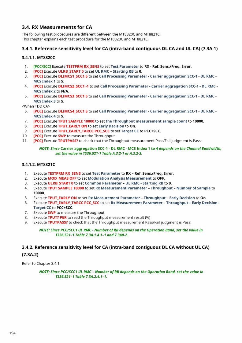
RX Measurements for CA 3.4.The following test procedures are different between the MT8820C and MT8821C. This chapter explains each test procedure for the MT8820C and MT8821C.
Reference sensitivity level for CA (intra-band contiguous DL CA and UL CA) (7.3A.1) 3.4.1. 3.4.1.1. MT8820C
1. [PCC/SCC] Execute TESTPRM RX_SENS to set Test Parameter to RX - Ref. Sens./Freq. Error. 2. [PCC] Execute ULRB_START 0 to set UL RMC – Starting RB to 0. 3. [PCC] Execute DLIMCS1_SCC1 5 to set Call Processing Parameter - Carrier aggregation SCC-1 - DL RMC -
MCS Index 1 to 5. 4. [PCC] Execute DLIMCS2_SCC1 -1 to set Call Processing Parameter - Carrier aggregation SCC-1 - DL RMC -
MCS Index 2 to N/A. 5. [PCC] Execute DLIMCS3_SCC1 5 to set Call Processing Parameter - Carrier aggregation SCC-1 - DL RMC -
MCS Index 3 to 5. <When TDD CA>
6. [PCC] Execute DLIMCS4_SCC1 5 to set Call Processing Parameter - Carrier aggregation SCC-1 - DL RMC - MCS Index 4 to 5.
7. [PCC] Execute TPUT SAMPLE 10000 to set the Throughput measurement sample count to 10000. 8. [PCC] Execute TPUT_EARLY ON to set Early Decision to On. 9. [PCC] Execute TPUT_EARLY_TARCC PCC_SCC to set Target CC to PCC+SCC.
10. [PCC] Execute SWP to measure the Throughput. 11. [PCC] Execute TPUTPASS? to check that the Throughput measurement Pass/Fail judgment is Pass.
NOTE: Since Carrier aggregation SCC-1 - DL RMC - MCS Index 1 to 4 depends on the Channel Bandwidth, set the value in TS36.521-1 Table A.3.2-1 or A.3.2-2.
3.4.1.2. MT8821C
1. Execute TESTPRM RX_SENS to set Test Parameter to RX – Ref. Sens./Freq. Error. 2. Execute MOD_MEAS OFF to set Modulation Analysis Measurement to OFF. 3. Execute ULRB_START 0 to set Common Parameter – UL RMC - Starting RB to 0. 4. Execute TPUT SAMPLE 10000 to set Rx Measurement Parameter – Throughput – Number of Sample to
10000. 5. Execute TPUT_EARLY ON to set Rx Measurement Parameter – Throughput – Early Decision to On. 6. Execute TPUT_EARLY_TARCC PCC_SCC to set Rx Measurement Parameter – Throughput – Early Decision -
Target CC to PCC+SCC. 7. Execute SWP to measure the Throughput. 8. Execute TPUT? PER to read the Throughput measurement result (%) 9. Execute TPUTPASS? to check that the Throughput measurement Pass/Fail judgment is Pass.
NOTE: Since PCC/SCC1 UL RMC - Number of RB depends on the Operation Band, set the value in
TS36.521–1 Table 7.3A.1.4.1–1 and 7.3A0-2.
Reference sensitivity level for CA (intra-band contiguous DL CA without UL CA) 3.4.2.(7.3A.2) Refer to Chapter 3.4.1.
NOTE: Since PCC/SCC1 UL RMC – Number of RB depends on the Operation Band, set the value in TS36.521–1 Table 7.3A.2.4.1–1.
194
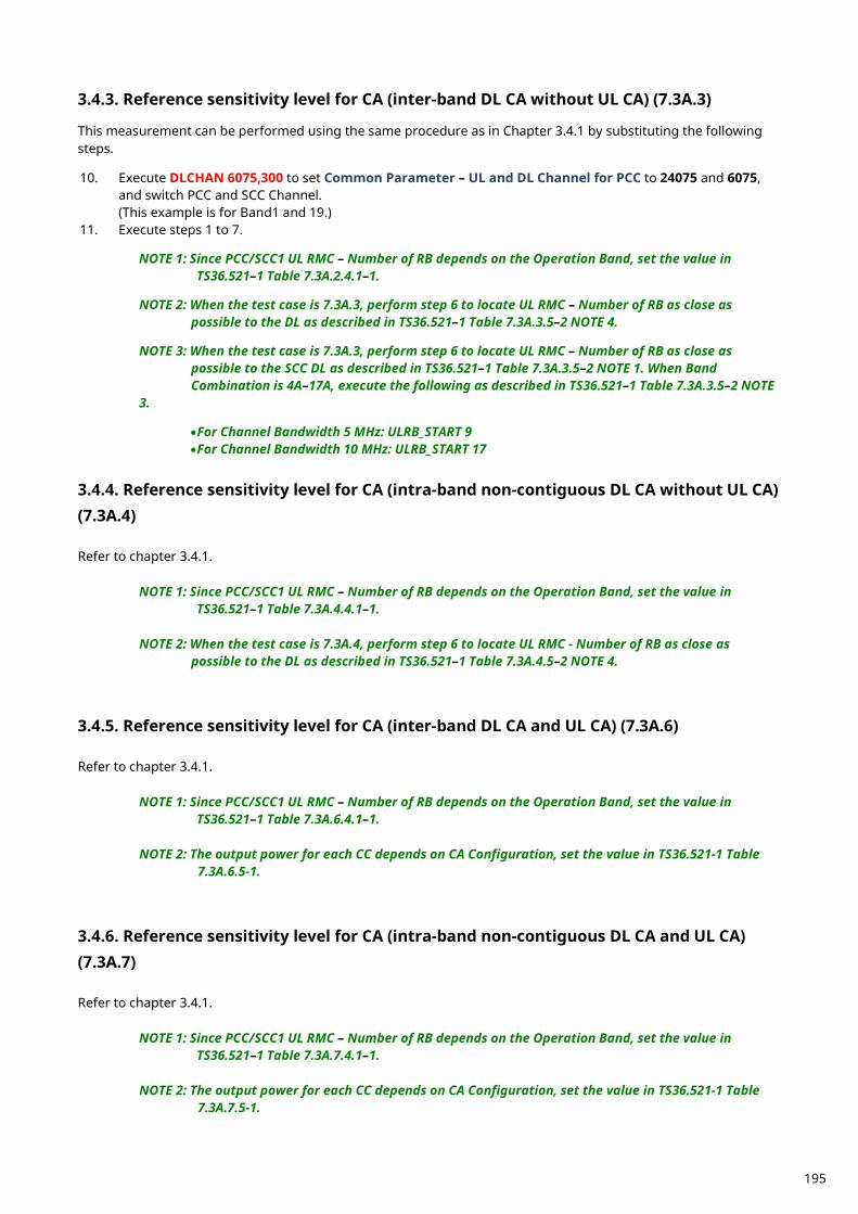
Reference sensitivity level for CA (inter-band DL CA without UL CA) (7.3A.3) 3.4.3. This measurement can be performed using the same procedure as in Chapter 3.4.1 by substituting the following steps. 10. Execute DLCHAN 6075,300 to set Common Parameter – UL and DL Channel for PCC to 24075 and 6075,
and switch PCC and SCC Channel. (This example is for Band1 and 19.)
11. Execute steps 1 to 7.
NOTE 1: Since PCC/SCC1 UL RMC – Number of RB depends on the Operation Band, set the value in TS36.521–1 Table 7.3A.2.4.1–1.
NOTE 2: When the test case is 7.3A.3, perform step 6 to locate UL RMC – Number of RB as close as
possible to the DL as described in TS36.521–1 Table 7.3A.3.5–2 NOTE 4.
NOTE 3: When the test case is 7.3A.3, perform step 6 to locate UL RMC – Number of RB as close as possible to the SCC DL as described in TS36.521–1 Table 7.3A.3.5–2 NOTE 1. When Band Combination is 4A–17A, execute the following as described in TS36.521–1 Table 7.3A.3.5–2 NOTE
3. •For Channel Bandwidth 5 MHz: ULRB_START 9 •For Channel Bandwidth 10 MHz: ULRB_START 17
Reference sensitivity level for CA (intra-band non-contiguous DL CA without UL CA) 3.4.4.(7.3A.4) Refer to chapter 3.4.1.
NOTE 1: Since PCC/SCC1 UL RMC – Number of RB depends on the Operation Band, set the value in TS36.521–1 Table 7.3A.4.4.1–1.
NOTE 2: When the test case is 7.3A.4, perform step 6 to locate UL RMC - Number of RB as close as
possible to the DL as described in TS36.521–1 Table 7.3A.4.5–2 NOTE 4.
Reference sensitivity level for CA (inter-band DL CA and UL CA) (7.3A.6) 3.4.5. Refer to chapter 3.4.1.
NOTE 1: Since PCC/SCC1 UL RMC – Number of RB depends on the Operation Band, set the value in TS36.521–1 Table 7.3A.6.4.1–1.
NOTE 2: The output power for each CC depends on CA Configuration, set the value in TS36.521-1 Table
7.3A.6.5-1.
Reference sensitivity level for CA (intra-band non-contiguous DL CA and UL CA) 3.4.6.(7.3A.7) Refer to chapter 3.4.1.
NOTE 1: Since PCC/SCC1 UL RMC – Number of RB depends on the Operation Band, set the value in TS36.521–1 Table 7.3A.7.4.1–1.
NOTE 2: The output power for each CC depends on CA Configuration, set the value in TS36.521-1 Table
7.3A.7.5-1.
195
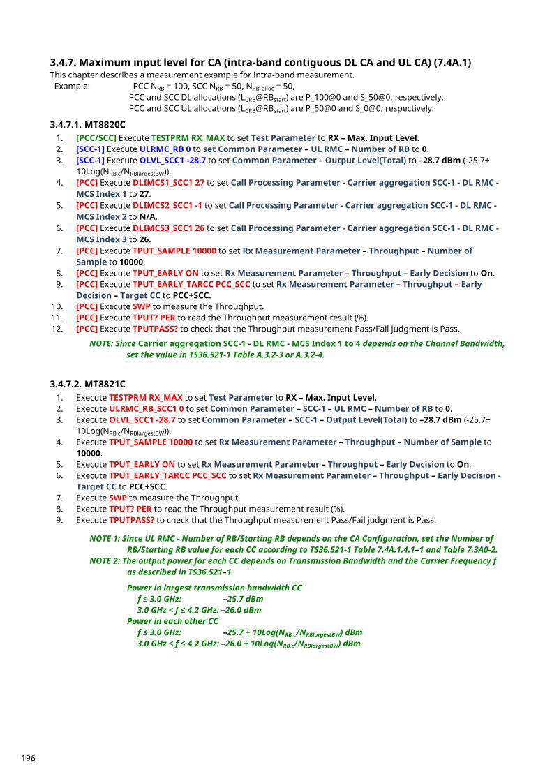
Maximum input level for CA (intra-band contiguous DL CA and UL CA) (7.4A.1) 3.4.7.This chapter describes a measurement example for intra-band measurement. Example: PCC NRB = 100, SCC NRB = 50, NRB_alloc = 50,
PCC and SCC DL allocations (LCRB@RBstart) are P_100@0 and S_50@0, respectively. PCC and SCC UL allocations (LCRB@RBstart) are P_50@0 and S_0@0, respectively.
3.4.7.1. MT8820C
1. [PCC/SCC] Execute TESTPRM RX_MAX to set Test Parameter to RX – Max. Input Level. 2. [SCC-1] Execute ULRMC_RB 0 to set Common Parameter – UL RMC – Number of RB to 0. 3. [SCC-1] Execute OLVL_SCC1 -28.7 to set Common Parameter – Output Level(Total) to –28.7 dBm (-25.7+
10Log(NRB,c/NRBlargestBW)). 4. [PCC] Execute DLIMCS1_SCC1 27 to set Call Processing Parameter - Carrier aggregation SCC-1 - DL RMC -
MCS Index 1 to 27. 5. [PCC] Execute DLIMCS2_SCC1 -1 to set Call Processing Parameter - Carrier aggregation SCC-1 - DL RMC -
MCS Index 2 to N/A. 6. [PCC] Execute DLIMCS3_SCC1 26 to set Call Processing Parameter - Carrier aggregation SCC-1 - DL RMC -
MCS Index 3 to 26. 7. [PCC] Execute TPUT_SAMPLE 10000 to set Rx Measurement Parameter – Throughput – Number of
Sample to 10000. 8. [PCC] Execute TPUT_EARLY ON to set Rx Measurement Parameter – Throughput – Early Decision to On. 9. [PCC] Execute TPUT_EARLY_TARCC PCC_SCC to set Rx Measurement Parameter – Throughput – Early
Decision – Target CC to PCC+SCC. 10. [PCC] Execute SWP to measure the Throughput. 11. [PCC] Execute TPUT? PER to read the Throughput measurement result (%). 12. [PCC] Execute TPUTPASS? to check that the Throughput measurement Pass/Fail judgment is Pass.
NOTE: Since Carrier aggregation SCC-1 - DL RMC - MCS Index 1 to 4 depends on the Channel Bandwidth, set the value in TS36.521-1 Table A.3.2-3 or A.3.2-4.
3.4.7.2. MT8821C 1. Execute TESTPRM RX_MAX to set Test Parameter to RX – Max. Input Level. 2. Execute ULRMC_RB_SCC1 0 to set Common Parameter – SCC-1 – UL RMC – Number of RB to 0. 3. Execute OLVL_SCC1 -28.7 to set Common Parameter – SCC-1 – Output Level(Total) to –28.7 dBm (-25.7+
10Log(NRB,c/NRBlargestBW)). 4. Execute TPUT_SAMPLE 10000 to set Rx Measurement Parameter – Throughput – Number of Sample to
10000. 5. Execute TPUT_EARLY ON to set Rx Measurement Parameter – Throughput – Early Decision to On. 6. Execute TPUT_EARLY_TARCC PCC_SCC to set Rx Measurement Parameter – Throughput – Early Decision -
Target CC to PCC+SCC. 7. Execute SWP to measure the Throughput. 8. Execute TPUT? PER to read the Throughput measurement result (%). 9. Execute TPUTPASS? to check that the Throughput measurement Pass/Fail judgment is Pass.
NOTE 1: Since UL RMC - Number of RB/Starting RB depends on the CA Configuration, set the Number of RB/Starting RB value for each CC according to TS36.521-1 Table 7.4A.1.4.1–1 and Table 7.3A0-2.
NOTE 2: The output power for each CC depends on Transmission Bandwidth and the Carrier Frequency f as described in TS36.521–1.
Power in largest transmission bandwidth CC
f ≤ 3.0 GHz: –25.7 dBm 3.0 GHz < f ≤ 4.2 GHz: –26.0 dBm
Power in each other CC f ≤ 3.0 GHz: –25.7 + 10Log(NRB,c/NRBlargestBW) dBm 3.0 GHz < f ≤ 4.2 GHz: –26.0 + 10Log(NRB,c/NRBlargestBW) dBm
196
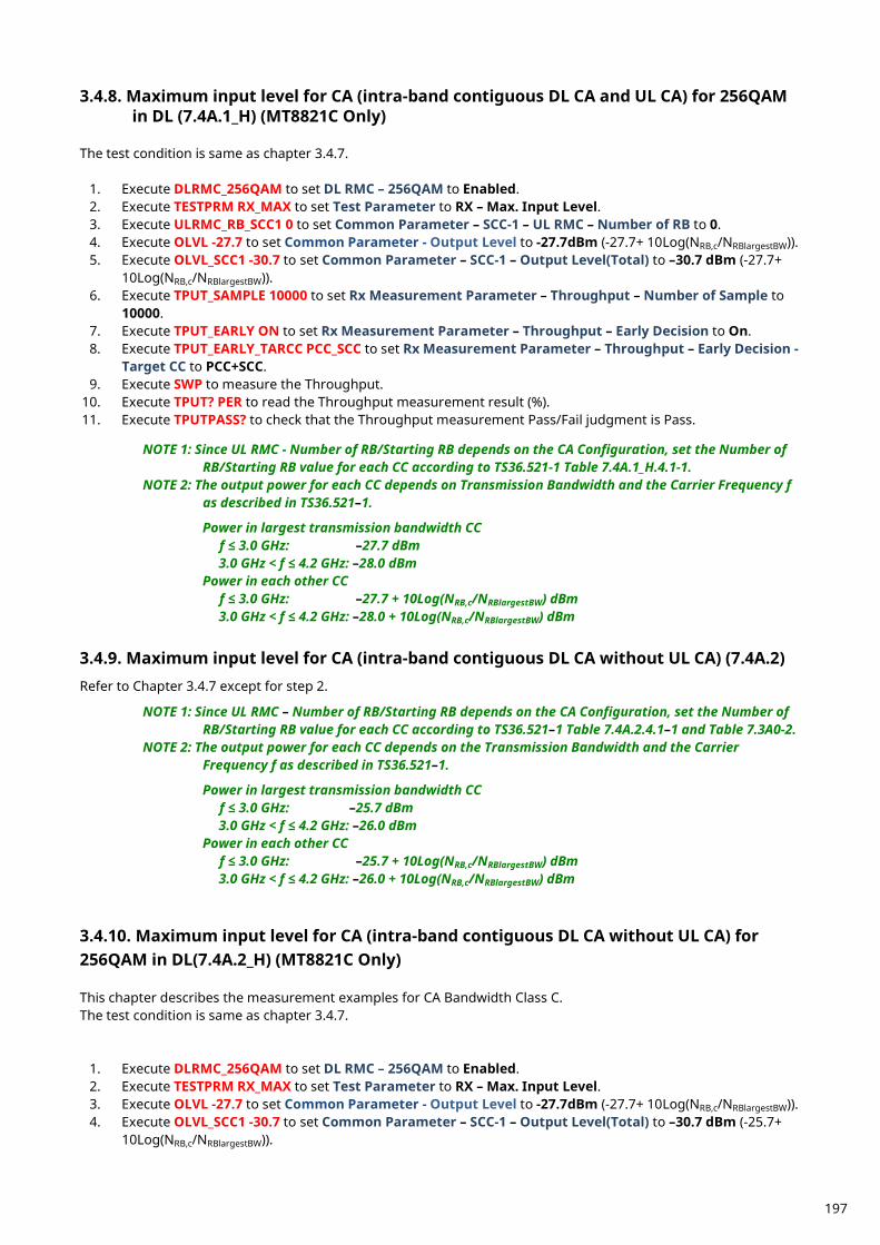
Maximum input level for CA (intra-band contiguous DL CA and UL CA) for 256QAM 3.4.8.in DL (7.4A.1_H) (MT8821C Only)
The test condition is same as chapter 3.4.7.
1. Execute DLRMC_256QAM to set DL RMC – 256QAM to Enabled. 2. Execute TESTPRM RX_MAX to set Test Parameter to RX – Max. Input Level. 3. Execute ULRMC_RB_SCC1 0 to set Common Parameter – SCC-1 – UL RMC – Number of RB to 0. 4. Execute OLVL -27.7 to set Common Parameter - Output Level to -27.7dBm (-27.7+ 10Log(NRB,c/NRBlargestBW)). 5. Execute OLVL_SCC1 -30.7 to set Common Parameter – SCC-1 – Output Level(Total) to –30.7 dBm (-27.7+
10Log(NRB,c/NRBlargestBW)). 6. Execute TPUT_SAMPLE 10000 to set Rx Measurement Parameter – Throughput – Number of Sample to
10000. 7. Execute TPUT_EARLY ON to set Rx Measurement Parameter – Throughput – Early Decision to On. 8. Execute TPUT_EARLY_TARCC PCC_SCC to set Rx Measurement Parameter – Throughput – Early Decision -
Target CC to PCC+SCC. 9. Execute SWP to measure the Throughput.
10. Execute TPUT? PER to read the Throughput measurement result (%). 11. Execute TPUTPASS? to check that the Throughput measurement Pass/Fail judgment is Pass.
NOTE 1: Since UL RMC - Number of RB/Starting RB depends on the CA Configuration, set the Number of RB/Starting RB value for each CC according to TS36.521-1 Table 7.4A.1_H.4.1-1.
NOTE 2: The output power for each CC depends on Transmission Bandwidth and the Carrier Frequency f as described in TS36.521–1.
Power in largest transmission bandwidth CC
f ≤ 3.0 GHz: –27.7 dBm 3.0 GHz < f ≤ 4.2 GHz: –28.0 dBm
Power in each other CC f ≤ 3.0 GHz: –27.7 + 10Log(NRB,c/NRBlargestBW) dBm 3.0 GHz < f ≤ 4.2 GHz: –28.0 + 10Log(NRB,c/NRBlargestBW) dBm
Maximum input level for CA (intra-band contiguous DL CA without UL CA) (7.4A.2) 3.4.9. Refer to Chapter 3.4.7 except for step 2.
NOTE 1: Since UL RMC – Number of RB/Starting RB depends on the CA Configuration, set the Number of RB/Starting RB value for each CC according to TS36.521–1 Table 7.4A.2.4.1–1 and Table 7.3A0-2.
NOTE 2: The output power for each CC depends on the Transmission Bandwidth and the Carrier Frequency f as described in TS36.521–1.
Power in largest transmission bandwidth CC
f ≤ 3.0 GHz: –25.7 dBm 3.0 GHz < f ≤ 4.2 GHz: –26.0 dBm
Power in each other CC f ≤ 3.0 GHz: –25.7 + 10Log(NRB,c/NRBlargestBW) dBm 3.0 GHz < f ≤ 4.2 GHz: –26.0 + 10Log(NRB,c/NRBlargestBW) dBm
Maximum input level for CA (intra-band contiguous DL CA without UL CA) for 3.4.10.256QAM in DL(7.4A.2_H) (MT8821C Only) This chapter describes the measurement examples for CA Bandwidth Class C. The test condition is same as chapter 3.4.7.
1. Execute DLRMC_256QAM to set DL RMC – 256QAM to Enabled. 2. Execute TESTPRM RX_MAX to set Test Parameter to RX – Max. Input Level. 3. Execute OLVL -27.7 to set Common Parameter - Output Level to -27.7dBm (-27.7+ 10Log(NRB,c/NRBlargestBW)). 4. Execute OLVL_SCC1 -30.7 to set Common Parameter – SCC-1 – Output Level(Total) to –30.7 dBm (-25.7+
10Log(NRB,c/NRBlargestBW)).
197
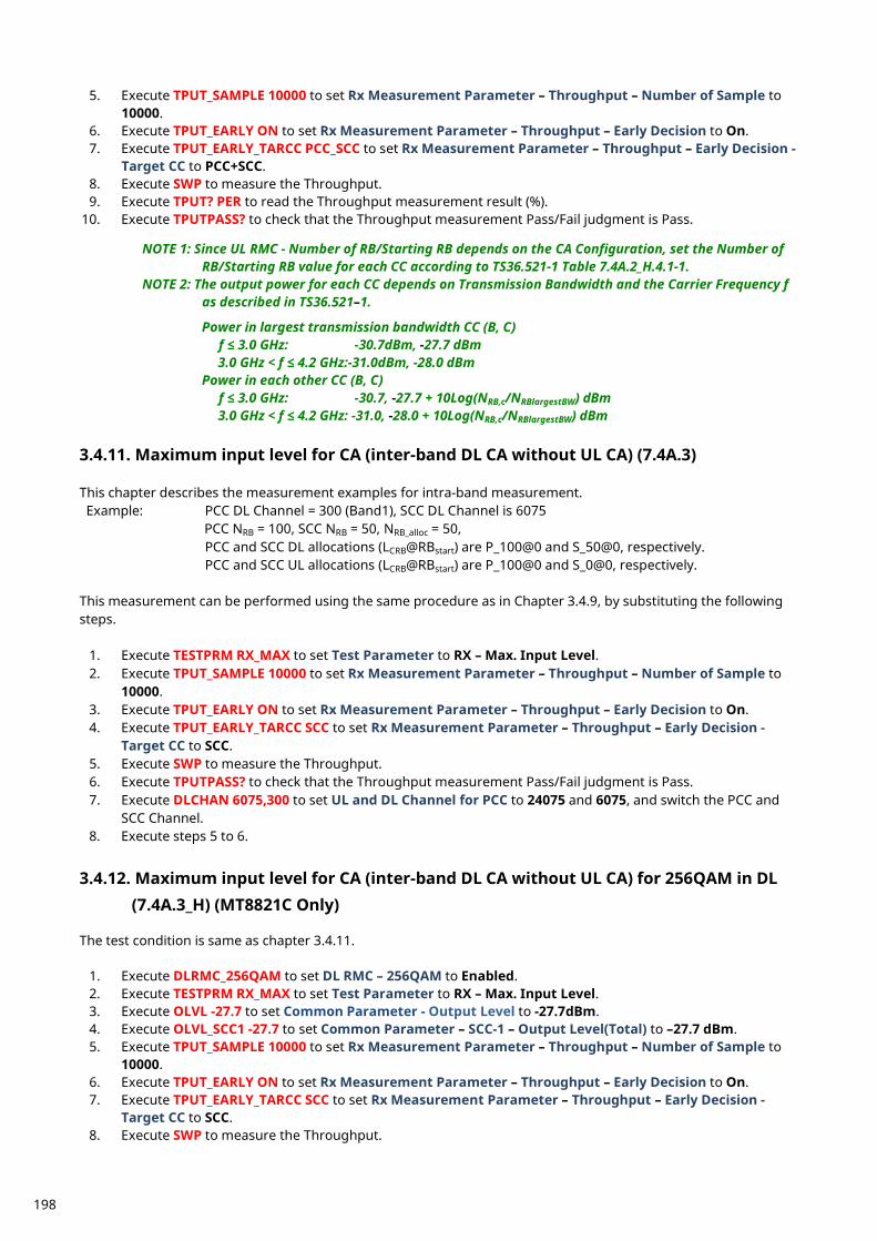
5. Execute TPUT_SAMPLE 10000 to set Rx Measurement Parameter – Throughput – Number of Sample to 10000.
6. Execute TPUT_EARLY ON to set Rx Measurement Parameter – Throughput – Early Decision to On. 7. Execute TPUT_EARLY_TARCC PCC_SCC to set Rx Measurement Parameter – Throughput – Early Decision -
Target CC to PCC+SCC. 8. Execute SWP to measure the Throughput. 9. Execute TPUT? PER to read the Throughput measurement result (%).
10. Execute TPUTPASS? to check that the Throughput measurement Pass/Fail judgment is Pass. NOTE 1: Since UL RMC - Number of RB/Starting RB depends on the CA Configuration, set the Number of
RB/Starting RB value for each CC according to TS36.521-1 Table 7.4A.2_H.4.1-1. NOTE 2: The output power for each CC depends on Transmission Bandwidth and the Carrier Frequency f
as described in TS36.521–1.
Power in largest transmission bandwidth CC (B, C) f ≤ 3.0 GHz: -30.7dBm, -27.7 dBm 3.0 GHz < f ≤ 4.2 GHz:-31.0dBm, -28.0 dBm
Power in each other CC (B, C) f ≤ 3.0 GHz: -30.7, -27.7 + 10Log(NRB,c/NRBlargestBW) dBm 3.0 GHz < f ≤ 4.2 GHz: -31.0, -28.0 + 10Log(NRB,c/NRBlargestBW) dBm
Maximum input level for CA (inter-band DL CA without UL CA) (7.4A.3) 3.4.11. This chapter describes the measurement examples for intra-band measurement. Example: PCC DL Channel = 300 (Band1), SCC DL Channel is 6075
PCC NRB = 100, SCC NRB = 50, NRB_alloc = 50, PCC and SCC DL allocations (LCRB@RBstart) are P_100@0 and S_50@0, respectively. PCC and SCC UL allocations (LCRB@RBstart) are P_100@0 and S_0@0, respectively.
This measurement can be performed using the same procedure as in Chapter 3.4.9, by substituting the following steps.
1. Execute TESTPRM RX_MAX to set Test Parameter to RX – Max. Input Level. 2. Execute TPUT_SAMPLE 10000 to set Rx Measurement Parameter – Throughput – Number of Sample to
10000. 3. Execute TPUT_EARLY ON to set Rx Measurement Parameter – Throughput – Early Decision to On. 4. Execute TPUT_EARLY_TARCC SCC to set Rx Measurement Parameter – Throughput – Early Decision -
Target CC to SCC. 5. Execute SWP to measure the Throughput. 6. Execute TPUTPASS? to check that the Throughput measurement Pass/Fail judgment is Pass. 7. Execute DLCHAN 6075,300 to set UL and DL Channel for PCC to 24075 and 6075, and switch the PCC and
SCC Channel. 8. Execute steps 5 to 6.
Maximum input level for CA (inter-band DL CA without UL CA) for 256QAM in DL 3.4.12.(7.4A.3_H) (MT8821C Only)
The test condition is same as chapter 3.4.11.
1. Execute DLRMC_256QAM to set DL RMC – 256QAM to Enabled. 2. Execute TESTPRM RX_MAX to set Test Parameter to RX – Max. Input Level. 3. Execute OLVL -27.7 to set Common Parameter - Output Level to -27.7dBm. 4. Execute OLVL_SCC1 -27.7 to set Common Parameter – SCC-1 – Output Level(Total) to –27.7 dBm. 5. Execute TPUT_SAMPLE 10000 to set Rx Measurement Parameter – Throughput – Number of Sample to
10000. 6. Execute TPUT_EARLY ON to set Rx Measurement Parameter – Throughput – Early Decision to On. 7. Execute TPUT_EARLY_TARCC SCC to set Rx Measurement Parameter – Throughput – Early Decision -
Target CC to SCC. 8. Execute SWP to measure the Throughput.
198
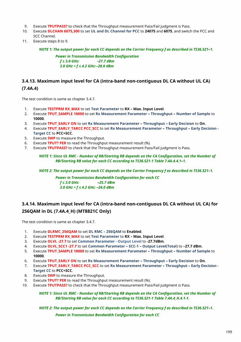
9. Execute TPUTPASS? to check that the Throughput measurement Pass/Fail judgment is Pass. 10. Execute DLCHAN 6075,300 to set UL and DL Channel for PCC to 24075 and 6075, and switch the PCC and
SCC Channel. 11. Execute steps 8 to 9.
NOTE 1: The output power for each CC depends on the Carrier Frequency f as described in TS36.521–1.
Power in Transmission Bandwidth Configuration f ≤ 3.0 GHz: -27.7 dBm 3.0 GHz < f ≤ 4.2 GHz:--28.0 dBm
Maximum input level for CA (intra-band non-contiguous DL CA without UL CA) 3.4.13.(7.4A.4) The test condition is same as chapter 3.4.7.
1. Execute TESTPRM RX_MAX to set Test Parameter to RX – Max. Input Level. 2. Execute TPUT_SAMPLE 10000 to set Rx Measurement Parameter – Throughput – Number of Sample to
10000. 3. Execute TPUT_EARLY ON to set Rx Measurement Parameter – Throughput – Early Decision to On. 4. Execute TPUT_EARLY_TARCC PCC_SCC to set Rx Measurement Parameter – Throughput – Early Decision -
Target CC to PCC+SCC. 5. Execute SWP to measure the Throughput. 6. Execute TPUT? PER to read the Throughput measurement result (%). 7. Execute TPUTPASS? to check that the Throughput measurement Pass/Fail judgment is Pass.
NOTE 1: Since UL RMC - Number of RB/Starting RB depends on the CA Configuration, set the Number of RB/Starting RB value for each CC according to TS36.521-1 Table 7.4A.4.4.1–1.
NOTE 2: The output power for each CC depends on the Carrier Frequency f as described in TS36.521–1.
Power in Transmission Bandwidth Configuration for each CC f ≤ 3.0 GHz: –25.7 dBm 3.0 GHz < f ≤ 4.2 GHz: –26.0 dBm
Maximum input level for CA (intra-band non-contiguous DL CA without UL CA) for 3.4.14.256QAM in DL (7.4A.4_H) (MT8821C Only) The test condition is same as chapter 3.4.7.
1. Execute DLRMC_256QAM to set DL RMC – 256QAM to Enabled. 2. Execute TESTPRM RX_MAX to set Test Parameter to RX – Max. Input Level. 3. Execute OLVL -27.7 to set Common Parameter - Output Level to -27.7dBm. 4. Execute OLVL_SCC1 -27.7 to set Common Parameter – SCC-1 – Output Level(Total) to –27.7 dBm. 5. Execute TPUT_SAMPLE 10000 to set Rx Measurement Parameter – Throughput – Number of Sample to
10000. 6. Execute TPUT_EARLY ON to set Rx Measurement Parameter – Throughput – Early Decision to On. 7. Execute TPUT_EARLY_TARCC PCC_SCC to set Rx Measurement Parameter – Throughput – Early Decision -
Target CC to PCC+SCC. 8. Execute SWP to measure the Throughput. 9. Execute TPUT? PER to read the Throughput measurement result (%).
10. Execute TPUTPASS? to check that the Throughput measurement Pass/Fail judgment is Pass. NOTE 1: Since UL RMC - Number of RB/Starting RB depends on the CA Configuration, set the Number of
RB/Starting RB value for each CC according to TS36.521-1 Table 7.4A.4_H.4.1-1. NOTE 2: The output power for each CC depends on the Carrier Frequency f as described in TS36.521–1.
Power in Transmission Bandwidth Configuration for each CC
199
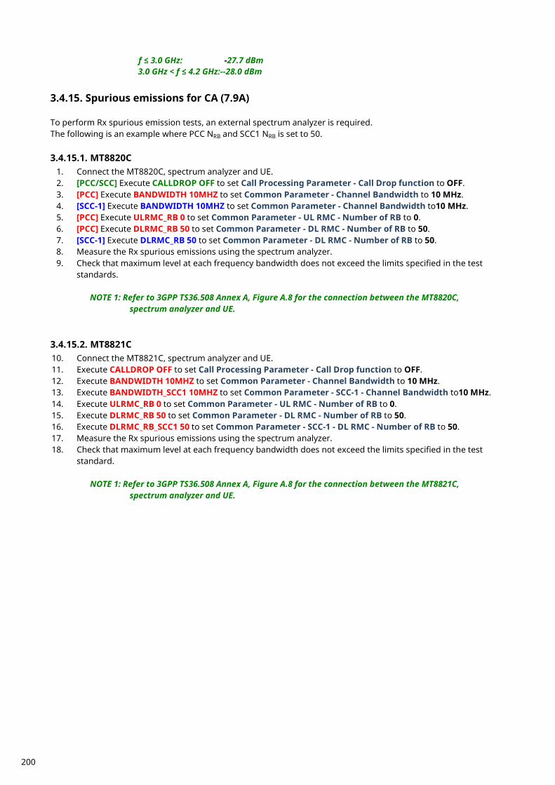
f ≤ 3.0 GHz: -27.7 dBm 3.0 GHz < f ≤ 4.2 GHz:--28.0 dBm
Spurious emissions for CA (7.9A) 3.4.15. To perform Rx spurious emission tests, an external spectrum analyzer is required. The following is an example where PCC NRB and SCC1 NRB is set to 50. 3.4.15.1. MT8820C
1. Connect the MT8820C, spectrum analyzer and UE. 2. [PCC/SCC] Execute CALLDROP OFF to set Call Processing Parameter - Call Drop function to OFF. 3. [PCC] Execute BANDWIDTH 10MHZ to set Common Parameter - Channel Bandwidth to 10 MHz. 4. [SCC-1] Execute BANDWIDTH 10MHZ to set Common Parameter - Channel Bandwidth to10 MHz. 5. [PCC] Execute ULRMC_RB 0 to set Common Parameter - UL RMC - Number of RB to 0. 6. [PCC] Execute DLRMC_RB 50 to set Common Parameter - DL RMC - Number of RB to 50. 7. [SCC-1] Execute DLRMC_RB 50 to set Common Parameter - DL RMC - Number of RB to 50. 8. Measure the Rx spurious emissions using the spectrum analyzer. 9. Check that maximum level at each frequency bandwidth does not exceed the limits specified in the test
standards. NOTE 1: Refer to 3GPP TS36.508 Annex A, Figure A.8 for the connection between the MT8820C, spectrum analyzer and UE. 3.4.15.2. MT8821C 10. Connect the MT8821C, spectrum analyzer and UE. 11. Execute CALLDROP OFF to set Call Processing Parameter - Call Drop function to OFF. 12. Execute BANDWIDTH 10MHZ to set Common Parameter - Channel Bandwidth to 10 MHz. 13. Execute BANDWIDTH_SCC1 10MHZ to set Common Parameter - SCC-1 - Channel Bandwidth to10 MHz. 14. Execute ULRMC_RB 0 to set Common Parameter - UL RMC - Number of RB to 0. 15. Execute DLRMC_RB 50 to set Common Parameter - DL RMC - Number of RB to 50. 16. Execute DLRMC_RB_SCC1 50 to set Common Parameter - SCC-1 - DL RMC - Number of RB to 50. 17. Measure the Rx spurious emissions using the spectrum analyzer. 18. Check that maximum level at each frequency bandwidth does not exceed the limits specified in the test
standard. NOTE 1: Refer to 3GPP TS36.508 Annex A, Figure A.8 for the connection between the MT8821C, spectrum analyzer and UE.
200
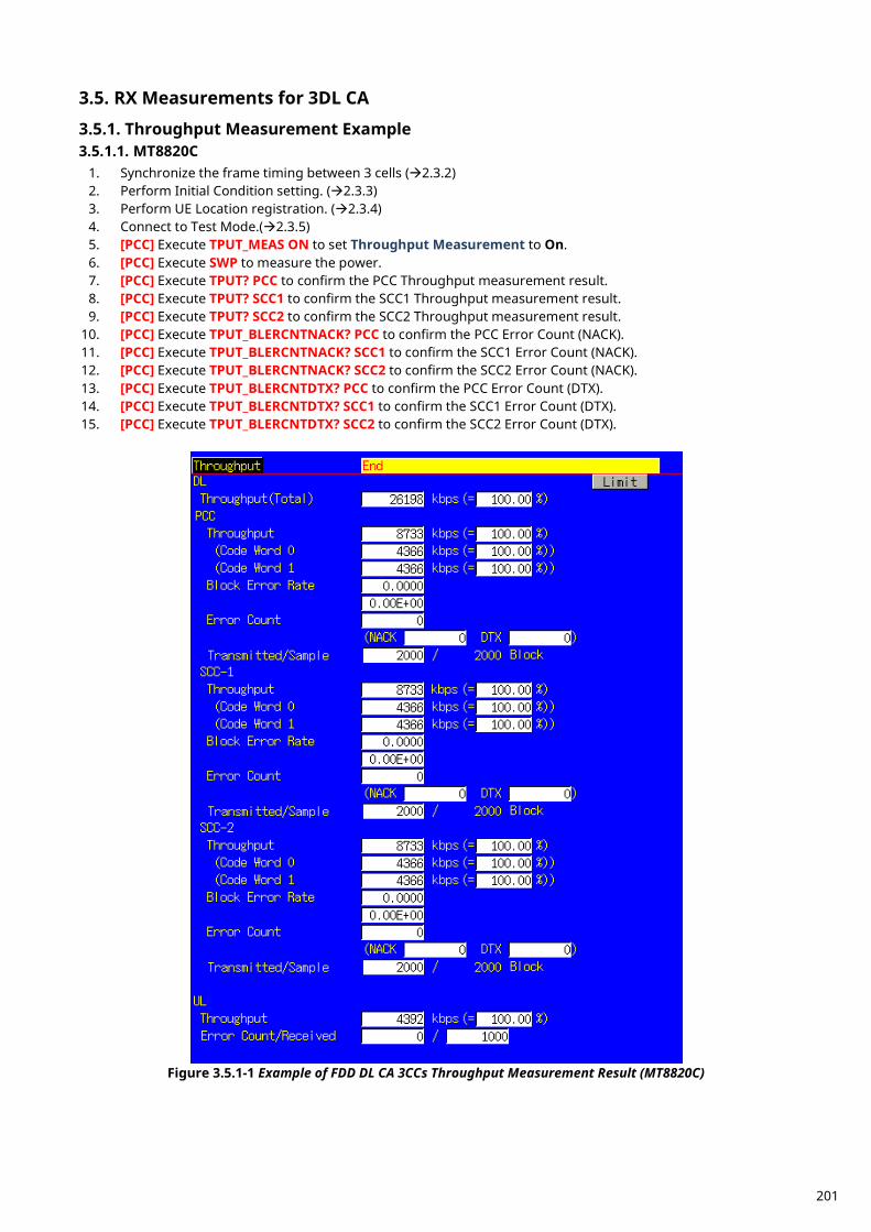
RX Measurements for 3DL CA 3.5.
Throughput Measurement Example 3.5.1.3.5.1.1. MT8820C
1. Synchronize the frame timing between 3 cells (2.3.2) 2. Perform Initial Condition setting. (2.3.3) 3. Perform UE Location registration. (2.3.4) 4. Connect to Test Mode.(2.3.5) 5. [PCC] Execute TPUT_MEAS ON to set Throughput Measurement to On. 6. [PCC] Execute SWP to measure the power. 7. [PCC] Execute TPUT? PCC to confirm the PCC Throughput measurement result. 8. [PCC] Execute TPUT? SCC1 to confirm the SCC1 Throughput measurement result. 9. [PCC] Execute TPUT? SCC2 to confirm the SCC2 Throughput measurement result.
10. [PCC] Execute TPUT_BLERCNTNACK? PCC to confirm the PCC Error Count (NACK). 11. [PCC] Execute TPUT_BLERCNTNACK? SCC1 to confirm the SCC1 Error Count (NACK). 12. [PCC] Execute TPUT_BLERCNTNACK? SCC2 to confirm the SCC2 Error Count (NACK). 13. [PCC] Execute TPUT_BLERCNTDTX? PCC to confirm the PCC Error Count (DTX). 14. [PCC] Execute TPUT_BLERCNTDTX? SCC1 to confirm the SCC1 Error Count (DTX). 15. [PCC] Execute TPUT_BLERCNTDTX? SCC2 to confirm the SCC2 Error Count (DTX).
Figure 3.5.1-1 Example of FDD DL CA 3CCs Throughput Measurement Result (MT8820C)
201
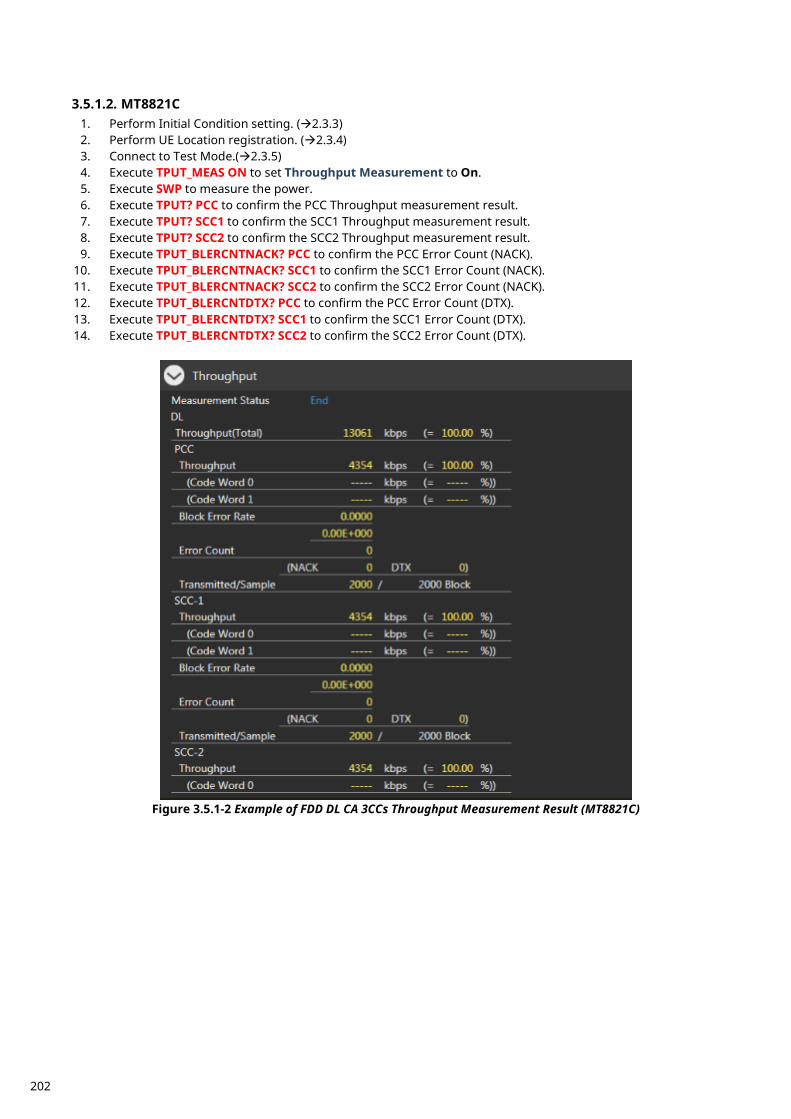
3.5.1.2. MT8821C
1. Perform Initial Condition setting. (2.3.3) 2. Perform UE Location registration. (2.3.4) 3. Connect to Test Mode.(2.3.5) 4. Execute TPUT_MEAS ON to set Throughput Measurement to On. 5. Execute SWP to measure the power. 6. Execute TPUT? PCC to confirm the PCC Throughput measurement result. 7. Execute TPUT? SCC1 to confirm the SCC1 Throughput measurement result. 8. Execute TPUT? SCC2 to confirm the SCC2 Throughput measurement result. 9. Execute TPUT_BLERCNTNACK? PCC to confirm the PCC Error Count (NACK).
10. Execute TPUT_BLERCNTNACK? SCC1 to confirm the SCC1 Error Count (NACK). 11. Execute TPUT_BLERCNTNACK? SCC2 to confirm the SCC2 Error Count (NACK). 12. Execute TPUT_BLERCNTDTX? PCC to confirm the PCC Error Count (DTX). 13. Execute TPUT_BLERCNTDTX? SCC1 to confirm the SCC1 Error Count (DTX). 14. Execute TPUT_BLERCNTDTX? SCC2 to confirm the SCC2 Error Count (DTX).
Figure 3.5.1-2 Example of FDD DL CA 3CCs Throughput Measurement Result (MT8821C)
202
Reference sensitivity level for CA (3DL with Intra-band contiguous CA) (7.3A.5) 3.5.2.This chapter describes a measurement example for 3DL with intra-band contiguous CA measurement. Example: PCC DL Channel = 39705 (Band41), SCC1 DL Channel = 39849 (Band41),
SCC2 DL Channel = 40020 (Band41) Lowest NRB_agg, PCC NRB = 100, SCC1 NRB = 100, SCC2 NRB = 75, PCC and SCC1 and SCC2 DL allocations (LCRB@RBstart) are P_100@0 and S1_100@0 and S2_75@0, respectively. PCC UL allocations (LCRB@RBstart) are P_50@0.
3.5.2.1. MT8820C
1. [PCC/SCC] Execute TESTPRM RX_SENS to set Test Parameter to RX - Ref. Sens./Freq. Error. 2. [PCC] Execute DLIMCS1_SCC1 5 to set Call Processing Parameter - Carrier aggregation SCC-1 - DL RMC -
MCS Index 1 to 5. 3. [PCC] Execute DLIMCS2_SCC1 -1 to set Call Processing Parameter - Carrier aggregation SCC-1 - DL RMC -
MCS Index 2 to N/A. 4. [PCC] Execute DLIMCS3_SCC1 5 to set Call Processing Parameter - Carrier aggregation SCC-1 - DL RMC -
MCS Index 3 to 5. 5. [PCC] Execute DLIMCS4_SCC1 5 to set Call Processing Parameter - Carrier aggregation SCC-1 - DL RMC -
MCS Index 4 to 5. 6. [PCC] Execute DLIMCS1_SCC2 5 to set Call Processing Parameter - Carrier aggregation SCC-2 - DL RMC -
MCS Index 1 to 5. 7. [PCC] Execute DLIMCS2_SCC2 -1 to set Call Processing Parameter - Carrier aggregation SCC-2 - DL RMC -
MCS Index 2 to N/A. 8. [PCC] Execute DLIMCS3_SCC2 5 to set Call Processing Parameter - Carrier aggregation SCC-2 - DL RMC -
MCS Index 3 to 5. 9. [PCC] Execute DLIMCS4_SCC2 5 to set Call Processing Parameter - Carrier aggregation SCC-2 - DL RMC -
MCS Index 4 to 5. 10. [PCC] Execute TPUT SAMPLE 10000 to set the Throughput measurement sample count to 10000. 11. [PCC] Execute TPUT_EARLY ON to set Early Decision to On. 12. [PCC] Execute TPUT_EARLY_TARCC PCC_SCC to set Target CC to PCC+SCC. 13. [PCC] Execute SWP to measure the Throughput. 14. [PCC] Execute TPUT? PER to read the Throughput measurement result (%). 15. [PCC] Execute TPUTPASS? to check that the Throughput measurement Pass/Fail judgment is Pass.
NOTE: Since the following parameters depend on the Channel Bandwidth, please set the values according to Table A.3.2-1 or A.3.2-2 in TS36.521-1. However, set DL RMC - MCS Index 4 only for TDD Bands. Carrier aggregation SCC-1 - DL RMC - MCS Index 1 to 4 Carrier aggregation SCC-2 - DL RMC - MCS Index 1 to 4
3.5.2.2. MT8821C
1. Execute TESTPRM RX_SENS to set Test Parameter to RX – Ref. Sens./Freq. Error. 2. Execute TPUT SAMPLE 10000 to set Rx Measurement Parameter – Throughput – Number of Sample to
10000. 3. Execute TPUT_EARLY ON to set Rx Measurement Parameter – Throughput – Early Decision to On.
<Ver30.40 or above> 4. Execute TPUT_EARLY_TARCC EACH to set Rx Measurement Parameter - Target CC to Each. 5. Execute TPUT_EARLY_EACH ON,ON,ON,OFF,OFF to set Rx Measurement Parameter - PCC, Rx
Measurement Parameter – SCC-1 and Rx Measurement Parameter - SCC-2 to On. 6. Execute SWP to measure the Throughput. 7. Execute TPUT? PER to read the Throughput measurement result (%)
203
8. Execute TPUTPASS? to check that the Throughput measurement Pass/Fail judgment is Pass. <Ver30.35 or lower>
4. Execute TPUT_EARLY_TARCC PCC_SCC to set Rx Measurement Parameter – Throughput – Early Decision - Target CC to PCC+SCC.
5. Execute SWP to measure the Throughput. 6. Execute TPUT? PER to read the Throughput measurement result (%) 7. Execute TPUTPASS? to check that the Throughput measurement Pass/Fail judgment is Pass.
NOTE 1: Since UL RMC - Number of RB/Starting RB depends on the Operation Band, please set the
Number of RB/Starting RB value for each CC according to TS36.521-1 Table 7.3A.5.4.1-1 and Table 7.3.5-2.
NOTE 2: Set the output power for each CC according to TS36.521-1 Table 7.3A.5.5-1.
Reference sensitivity level for CA (3DL with Inter-band CA) (7.3A.5) 3.5.3.This chapter describes a measurement example for 3DL with inter-band CA measurement. Example: PCC DL Channel = 300 (Band1), SCC1 DL Channel = 1850 (Band3),
SCC2 DL Channel = 6100 (Band19) PCC NRB = 100, SCC1 NRB = 100, SCC2 NRB = 50, PCC and SCC1 and SCC2 DL allocations (LCRB@RBstart) are P_100@0 and S1_100@0 and S2_50@0, respectively. PCC UL allocations (LCRB@RBstart) are P_45@0.
3.5.3.1. MT8820C
1. [PCC/SCC] Execute TESTPRM RX_SENS to set Test Parameter to RX - Ref. Sens./Freq. Error. 2. [PCC] Execute DLIMCS1_SCC1 5 to set Call Processing Parameter - Carrier aggregation SCC-1 - DL RMC -
MCS Index 1 to 5. 3. [PCC] Execute DLIMCS2_SCC1 -1 to set Call Processing Parameter - Carrier aggregation SCC-1 - DL RMC -
MCS Index 2 to N/A. 4. [PCC] Execute DLIMCS3_SCC1 5 to set Call Processing Parameter - Carrier aggregation SCC-1 - DL RMC -
MCS Index 3 to 5. 5. [PCC] Execute DLIMCS1_SCC2 5 to set Call Processing Parameter - Carrier aggregation SCC-2 - DL RMC -
MCS Index 1 to 5. 6. [PCC] Execute DLIMCS2_SCC2 -1 to set Call Processing Parameter - Carrier aggregation SCC-2 - DL RMC -
MCS Index 2 to N/A. 7. [PCC] Execute DLIMCS3_SCC2 5 to set Call Processing Parameter - Carrier aggregation SCC-2 - DL RMC -
MCS Index 3 to 5. 8. [PCC] Execute TPUT SAMPLE 10000 to set the Throughput measurement sample count to 10000. 9. [PCC] Execute TPUT_EARLY ON to set Early Decision to On.
10. [PCC] Execute TPUT_EARLY_TARCC PCC_SCC to set Target CC to PCC+SCC. 11. [PCC] Execute SWP to measure the Throughput. 12. [PCC] Execute TPUT? PER to read the Throughput measurement result (%). 13. [PCC] Execute TPUTPASS? to check that the Throughput measurement Pass/Fail judgment is Pass.
NOTE: Since the following parameters depend on the Channel Bandwidth, please set the values according to Table A.3.2-1 or A.3.2-2 in TS36.521-1. However, set DL RMC - MCS Index 4 only for TDD Bands. Carrier aggregation SCC-1 - DL RMC - MCS Index 1 to 4 Carrier aggregation SCC-2 - DL RMC - MCS Index 1 to 4
204
3.5.3.2. MT8821C
1. Execute TESTPRM RX_SENS to set Test Parameter to RX – Ref. Sens./Freq. Error. 2. Execute TPUT SAMPLE 10000 to set Rx Measurement Parameter – Throughput – Number of Sample to
10000. 3. Execute TPUT_EARLY ON to set Rx Measurement Parameter – Throughput – Early Decision to On.
<Ver30.40 or above> 4. Execute TPUT_EARLY_TARCC EACH to set Rx Measurement Parameter - Target CC to Each. 5. Execute TPUT_EARLY_EACH ON,ON,ON,OFF,OFF to set Rx Measurement Parameter - PCC, Rx
Measurement Parameter – SCC-1 and Rx Measurement Parameter - SCC-2 to On. 6. Execute SWP to measure the Throughput. 7. Execute TPUT? PER to read the Throughput measurement result (%) 8. Execute TPUTPASS? to check that the Throughput measurement Pass/Fail judgment is Pass.
<Ver30.35 or lower> 4. Execute TPUT_EARLY_TARCC PCC_SCC to set Rx Measurement Parameter – Throughput – Early Decision -
Target CC to PCC+SCC. 5. Execute SWP to measure the Throughput. 6. Execute TPUT? PER to read the Throughput measurement result (%) 7. Execute TPUTPASS? to check that the Throughput measurement Pass/Fail judgment is Pass.
NOTE 1: Since UL RMC - Number of RB/Starting RB depends on the Operation Band, set the Number of
RB/Starting RB value for each CC according to TS36.521-1 Table 7.3A.5.4.1-2 and Table 7.3.5-2. NOTE 2: Set the output power for each CC according to TS36.521-1 Table 7.3A.5.5-3.
Reference sensitivity level for CA (3DL with Intra-band contiguous + Inter-band CA) 3.5.4.(7.3A.5) This chapter describes a measurement example for 3DL with intra-band contiguous and inter-band CA measurement. Example: PCC DL Channel = 1300 (Band3), SCC1 DL Channel = 1498 (Band3),
SCC2 DL Channel = 3100 (Band7) Highest NRB_agg, PCC NRB = 100, SCC1 NRB = 100, SCC2 NRB = 100, PCC and SCC1 and SCC2 DL allocations (LCRB@RBstart) are P_100@0 and S1_100@0 and S2_100@0, respectively. PCC UL allocations (LCRB@RBstart) are P_100@0.
3.5.4.1. MT8820C
1. [PCC/SCC] Execute TESTPRM RX_SENS to set Test Parameter to RX - Ref. Sens./Freq. Error. 2. [PCC] Execute DLIMCS1_SCC1 5 to set Call Processing Parameter - Carrier aggregation SCC-1 - DL RMC -
MCS Index 1 to 5. 3. [PCC] Execute DLIMCS2_SCC1 -1 to set Call Processing Parameter - Carrier aggregation SCC-1 - DL RMC -
MCS Index 2 to N/A. 4. [PCC] Execute DLIMCS3_SCC1 5 to set Call Processing Parameter - Carrier aggregation SCC-1 - DL RMC -
MCS Index 3 to 5. 5. [PCC] Execute DLIMCS1_SCC2 5 to set Call Processing Parameter - Carrier aggregation SCC-2 - DL RMC -
MCS Index 1 to 5. 6. [PCC] Execute DLIMCS2_SCC2 -1 to set Call Processing Parameter - Carrier aggregation SCC-2 - DL RMC -
MCS Index 2 to N/A. 7. [PCC] Execute DLIMCS3_SCC2 5 to set Call Processing Parameter - Carrier aggregation SCC-2 - DL RMC -
MCS Index 3 to 5. 8. [PCC] Execute TPUT SAMPLE 10000 to set the Throughput measurement sample count to 10000. 9. [PCC] Execute TPUT_EARLY ON to set Early Decision to On.
10. [PCC] Execute TPUT_EARLY_TARCC PCC_SCC to set Target CC to PCC+SCC.
205
11. [PCC] Execute SWP to measure the Throughput. 12. [PCC] Execute TPUT? PER to read the Throughput measurement result (%). 13. [PCC] Execute TPUTPASS? to check that the Throughput measurement Pass/Fail judgment is Pass.
NOTE: Since the following parameters depend on the Channel Bandwidth, please set the values according to Table A.3.2-1 or A.3.2-2 in TS36.521-1. However, set DL RMC - MCS Index 4 only for TDD Bands. Carrier aggregation SCC-1 - DL RMC - MCS Index 1 to 4 Carrier aggregation SCC-2 - DL RMC - MCS Index 1 to 4
3.5.4.2. MT8821C
1. Execute TESTPRM RX_SENS to set Test Parameter to RX – Ref. Sens./Freq. Error. 2. Execute TPUT SAMPLE 10000 to set Rx Measurement Parameter – Throughput – Number of Sample to
10000. 3. Execute TPUT_EARLY ON to set Rx Measurement Parameter – Throughput – Early Decision to On.
<Ver30.40 or above> 4. Execute TPUT_EARLY_TARCC EACH to set Rx Measurement Parameter - Target CC to Each. 5. Execute TPUT_EARLY_EACH ON,ON,ON,OFF,OFF to set Rx Measurement Parameter - PCC, Rx
Measurement Parameter – SCC-1 and Rx Measurement Parameter - SCC-2 to On. 6. Execute SWP to measure the Throughput. 7. Execute TPUT? PER to read the Throughput measurement result (%) 8. Execute TPUTPASS? to check that the Throughput measurement Pass/Fail judgment is Pass.
<Ver30.35 or lower> 4. Execute TPUT_EARLY_TARCC PCC_SCC to set Rx Measurement Parameter – Throughput – Early Decision -
Target CC to PCC+SCC. 5. Execute SWP to measure the Throughput. 6. Execute TPUT? PER to read the Throughput measurement result (%) 7. Execute TPUTPASS? to check that the Throughput measurement Pass/Fail judgment is Pass.
NOTE 1: Since UL RMC - Number of RB/Starting RB depends on the Operation Band, set the Number of
RB/Starting RB value for each CC according to TS36.521-1 Table 7.3A.5.4.1-3 and Table 7.3.5-2. NOTE 2: Set the output power for each CC according to TS36.521-1 Table 7.3A.5.5-5.
Reference sensitivity level for CA (3DL with Intra-band non- contiguous + 3.5.5.Inter-band CA) (7.3A.5) This chapter describes a measurement example for 3DL with intra-band non-contiguous and inter-band CA measurement. Example: PCC DL Channel = 2525 (Band5), SCC1 DL Channel = 1100 (Band2),
SCC2 DL Channel = 700 (Band2) PCC NRB = 50, SCC1 NRB = 100, SCC2 NRB = 100, PCC and SCC1 and SCC2 DL allocations (LCRB@RBstart) are P_50@0 and S1_100@0 and S2_100@0, respectively. PCC UL allocations (LCRB@RBstart) are P_25@0.
3.5.5.1. MT8820C
1. [PCC/SCC] Execute TESTPRM RX_SENS to set Test Parameter to RX - Ref. Sens./Freq. Error. 2. [PCC] Execute OLVL -95.0 to set Common Parameter – Output Level(Total) to –95.0 dBm. 3. [PCC] Execute DLIMCS1_SCC1 5 to set Call Processing Parameter - Carrier aggregation SCC-1 - DL RMC -
MCS Index 1 to 5. 4. [PCC] Execute DLIMCS2_SCC1 -1 to set Call Processing Parameter - Carrier aggregation SCC-1 - DL RMC -
MCS Index 2 to N/A.
206
5. [PCC] Execute DLIMCS3_SCC1 5 to set Call Processing Parameter - Carrier aggregation SCC-1 - DL RMC - MCS Index 3 to 5.
6. [PCC] Execute DLIMCS1_SCC2 5 to set Call Processing Parameter - Carrier aggregation SCC-2 - DL RMC - MCS Index 1 to 5.
7. [PCC] Execute DLIMCS2_SCC2 -1 to set Call Processing Parameter - Carrier aggregation SCC-2 - DL RMC - MCS Index 2 to N/A.
8. [PCC] Execute DLIMCS3_SCC2 5 to set Call Processing Parameter - Carrier aggregation SCC-2 - DL RMC - MCS Index 3 to 5.
9. [PCC] Execute TPUT SAMPLE 10000 to set the Throughput measurement sample count to 10000. 10. [PCC] Execute TPUT_EARLY ON to set Early Decision to On. 11. [PCC] Execute TPUT_EARLY_TARCC PCC_SCC to set Target CC to PCC+SCC. 12. [PCC] Execute SWP to measure the Throughput. 13. [PCC] Execute TPUT? PER to read the Throughput measurement result (%). 14. [PCC] Execute TPUTPASS? to check that the Throughput measurement Pass/Fail judgment is Pass.
NOTE: Since the following parameters depend on the Channel Bandwidth, please set the values according to Table A.3.2-1 or A.3.2-2 in TS36.521-1. However, set DL RMC - MCS Index 4 only for TDD Bands. Carrier aggregation SCC-1 - DL RMC - MCS Index 1 to 4 Carrier aggregation SCC-2 - DL RMC - MCS Index 1 to 4
3.5.5.2. MT8821C
1. Execute TESTPRM RX_SENS to set Test Parameter to RX – Ref. Sens./Freq. Error. 2. Execute OLVL -95.0 to set Common Parameter – Output Level(Total) to –95.0 dBm. 3. Execute TPUT SAMPLE 10000 to set Rx Measurement Parameter – Throughput – Number of Sample to
10000. 4. Execute TPUT_EARLY ON to set Rx Measurement Parameter – Throughput – Early Decision to On.
<Ver30.40 or above> 5. Execute TPUT_EARLY_TARCC EACH to set Rx Measurement Parameter - Target CC to Each. 6. Execute TPUT_EARLY_EACH ON,ON,ON,OFF,OFF to set Rx Measurement Parameter - PCC, Rx
Measurement Parameter – SCC-1 and Rx Measurement Parameter - SCC-2 to On. 7. Execute SWP to measure the Throughput. 8. Execute TPUT? PER to read the Throughput measurement result (%) 9. Execute TPUTPASS? to check that the Throughput measurement Pass/Fail judgment is Pass.
<Ver30.35 or lower> 5. Execute TPUT_EARLY_TARCC PCC_SCC to set Rx Measurement Parameter – Throughput – Early Decision -
Target CC to PCC+SCC. 6. Execute SWP to measure the Throughput. 7. Execute TPUT? PER to read the Throughput measurement result (%) 8. Execute TPUTPASS? to check that the Throughput measurement Pass/Fail judgment is Pass.
NOTE 1: Since UL RMC - Number of RB/Starting RB depends on the Operation Band, set the Number of
RB/Starting RB value for each CC according to TS36.521-1 Table 7.3A.5.4.1-4 and Table 7.3.5-2. NOTE 2: Set the output power for each CC according to TS36.521-1 Table 7.3A.5.5-6.
Reference sensitivity level for CA (3DL with Intra-band non- contiguous + 3.5.6.Intra-band CA) (7.3A.5) This chapter describes a measurement example for 3DL with intra-band non-contiguous and intra-band CA measurement. Example: PCC DL Channel = 41490 (Band41), SCC1 DL Channel = 41292 (Band41),
SCC2 DL Channel = 39750 (Band41) PCC NRB = 100, SCC1 NRB = 100, SCC2 NRB = 100, PCC and SCC1 and SCC2 DL allocations (LCRB@RBstart) are P_100@0 and S1_100@0 and S2_100@0, respectively. PCC UL allocations (LCRB@RBstart) are P_100@0.
207
3.5.6.1. MT8820C
1. [PCC/SCC] Execute TESTPRM RX_SENS to set Test Parameter to RX - Ref. Sens./Freq. Error. 2. [PCC] Execute OLVL -95.0 to set Common Parameter – Output Level(Total) to –95.0 dBm. 3. [PCC] Execute DLIMCS1_SCC1 5 to set Call Processing Parameter - Carrier aggregation SCC-1 - DL RMC -
MCS Index 1 to 5. 4. [PCC] Execute DLIMCS2_SCC1 -1 to set Call Processing Parameter - Carrier aggregation SCC-1 - DL RMC -
MCS Index 2 to N/A. 5. [PCC] Execute DLIMCS3_SCC1 5 to set Call Processing Parameter - Carrier aggregation SCC-1 - DL RMC -
MCS Index 3 to 5. 6. [PCC] Execute DLIMCS4_SCC1 5 to set Call Processing Parameter - Carrier aggregation SCC-1 - DL RMC -
MCS Index 4 to 5. 7. [PCC] Execute DLIMCS1_SCC2 5 to set Call Processing Parameter - Carrier aggregation SCC-2 - DL RMC -
MCS Index 1 to 5. 8. [PCC] Execute DLIMCS2_SCC2 -1 to set Call Processing Parameter - Carrier aggregation SCC-2 - DL RMC -
MCS Index 2 to N/A. 9. [PCC] Execute DLIMCS3_SCC2 5 to set Call Processing Parameter - Carrier aggregation SCC-2 - DL RMC -
MCS Index 3 to 5. 10. [PCC] Execute DLIMCS4_SCC2 5 to set Call Processing Parameter - Carrier aggregation SCC-2 - DL RMC -
MCS Index 4 to 5. 11. [PCC] Execute TPUT SAMPLE 10000 to set the Throughput measurement sample count to 10000. 12. [PCC] Execute TPUT_EARLY ON to set Early Decision to On. 13. [PCC] Execute TPUT_EARLY_TARCC PCC_SCC to set Target CC to PCC+SCC. 14. [PCC] Execute SWP to measure the Throughput. 15. [PCC] Execute TPUT? PER to read the Throughput measurement result (%). 16. [PCC] Execute TPUTPASS? to check that the Throughput measurement Pass/Fail judgment is Pass.
NOTE: Since the following parameters depend on the Channel Bandwidth, please set the values according to Table A.3.2-1 or A.3.2-2 in TS36.521-1. However, set DL RMC - MCS Index 4 only for TDD Bands. Carrier aggregation SCC-1 - DL RMC - MCS Index 1 to 4 Carrier aggregation SCC-2 - DL RMC - MCS Index 1 to 4
3.5.6.2. MT8821C
1. Execute TESTPRM RX_SENS to set Test Parameter to RX – Ref. Sens./Freq. Error. 2. Execute TPUT SAMPLE 10000 to set Rx Measurement Parameter – Throughput – Number of Sample to
10000. 3. Execute TPUT_EARLY ON to set Rx Measurement Parameter – Throughput – Early Decision to On.
<Ver30.40 or above> 4. Execute TPUT_EARLY_TARCC EACH to set Rx Measurement Parameter - Target CC to Each. 5. Execute TPUT_EARLY_EACH ON,ON,ON,OFF,OFF to set Rx Measurement Parameter - PCC, Rx
Measurement Parameter – SCC-1 and Rx Measurement Parameter - SCC-2 to On. 6. Execute SWP to measure the Throughput. 7. Execute TPUT? PER to read the Throughput measurement result (%) 8. Execute TPUTPASS? to check that the Throughput measurement Pass/Fail judgment is Pass.
<Ver30.35 or lower> 4. Execute TPUT_EARLY_TARCC PCC_SCC to set Rx Measurement Parameter – Throughput – Early Decision -
Target CC to PCC+SCC. 5. Execute SWP to measure the Throughput. 6. Execute TPUT? PER to read the Throughput measurement result (%) 7. Execute TPUTPASS? to check that the Throughput measurement Pass/Fail judgment is Pass.
NOTE 1: Since UL RMC - Number of RB/Starting RB depends on the Operation Band, set the Number of
RB/Starting RB value for each CC according to TS36.521-1 Table 7.3A.5.4.1-5 and Table 7.3.5-2. NOTE 2: Set the output power for each CC according to TS36.521-1 Table 7.3A.5.5-7.
208
Maximum input level for CA (3DL with Intra-band contiguous CA) (7.4A.5) 3.5.7.This chapter describes a measurement example for 3DL with intra-band contiguous CA measurement. Example: PCC DL Channel = 40451 (Band41), SCC1 DL Channel = 40595 (Band41),
SCC2 DL Channel = 40766 (Band41) Lowest NRB_agg, PCC NRB = 50, SCC1 NRB = 100, SCC2 NRB = 75, PCC and SCC1 and SCC2 DL allocations (LCRB@RBstart) are P_50@0 and S1_100@0 and S2_75@0, respectively. PCC UL allocations (LCRB@RBstart) are P_50@0.
3.5.7.1. MT8820C
1. [PCC/SCC] Execute TESTPRM RX_MAX to set Test Parameter to RX – Max. Input Level. 2. [PCC] Execute OLVL -28.7 to set Common Parameter – Output Level(Total) to –28.7 dBm (-25.7+
10Log(NRB,c/NRBlargestBW)). 3. [SCC-1] Execute OLVL_SCC1 -25.7 to set Common Parameter – Output Level(Total) to –25.7 dBm (-25.7+
10Log(NRB,c/NRBlargestBW)). 4. [SCC-2] Execute OLVL_SCC2 -26.9 to set Common Parameter – Output Level(Total) to –26.9 dBm (-25.7+
10Log(NRB,c/NRBlargestBW)). 5. [PCC] Execute DLIMCS1_SCC1 26 to set Call Processing Parameter - Carrier aggregation SCC-1 - DL RMC -
MCS Index 1 to 26. 6. [PCC] Execute DLIMCS2_SCC1 -1 to set Call Processing Parameter - Carrier aggregation SCC-1 - DL RMC -
MCS Index 2 to N/A. 7. [PCC] Execute DLIMCS3_SCC1 26 to set Call Processing Parameter - Carrier aggregation SCC-1 - DL RMC -
MCS Index 3 to 26. 8. [PCC] Execute DLIMCS4_SCC1 27 to set Call Processing Parameter - Carrier aggregation SCC-1 - DL RMC -
MCS Index 4 to 27. 9. [PCC] Execute DLIMCS1_SCC2 27 to set Call Processing Parameter - Carrier aggregation SCC-2 - DL RMC -
MCS Index 1 to 27. 10. [PCC] Execute DLIMCS2_SCC2 -1 to set Call Processing Parameter - Carrier aggregation SCC-2 - DL RMC -
MCS Index 2 to N/A. 11. [PCC] Execute DLIMCS3_SCC2 26 to set Call Processing Parameter - Carrier aggregation SCC-2 - DL RMC -
MCS Index 3 to 26. 12. [PCC] Execute DLIMCS4_SCC2 27 to set Call Processing Parameter - Carrier aggregation SCC-2 - DL RMC -
MCS Index 4 to 27. 13. [PCC] Execute TPUT SAMPLE 10000 to set the Throughput measurement sample count to 10000. 14. [PCC] Execute TPUT_EARLY ON to set Early Decision to On. 15. [PCC] Execute TPUT_EARLY_TARCC PCC_SCC to set Target CC to PCC+SCC. 16. [PCC] Execute SWP to measure the Throughput. 17. [PCC] Execute TPUT? PER to read the Throughput measurement result (%). 18. [PCC] Execute TPUTPASS? to check that the Throughput measurement Pass/Fail judgment is Pass.
NOTE: Since the following parameters depend on the Channel Bandwidth, please set the values according to Table A.3.2-3 or A.3.2-4 in TS36.521-1. However, set DL RMC - MCS Index 4 only for TDD Bands. Carrier aggregation SCC-1 - DL RMC - MCS Index 1 to 4 Carrier aggregation SCC-2 - DL RMC - MCS Index 1 to 4
3.5.7.2. MT8821C
1. Execute TESTPRM RX_MAX to set Test Parameter to RX – Max. Input Level. 2. Execute OLVL -28.7 to set Common Parameter – Output Level(Total) to –28.7 dBm (-25.7+
10Log(NRB,c/NRBlargestBW)). 3. Execute OLVL_SCC1 -25.7 to set Common Parameter – SCC-1 – Output Level(Total) to –25.7 dBm (-25.7+
10Log(NRB,c/NRBlargestBW)). 4. Execute OLVL_SCC2 -26.9 to set Common Parameter – SCC-2 – Output Level(Total) to –26.9 dBm (-25.7+
10Log(NRB,c/NRBlargestBW)).
209
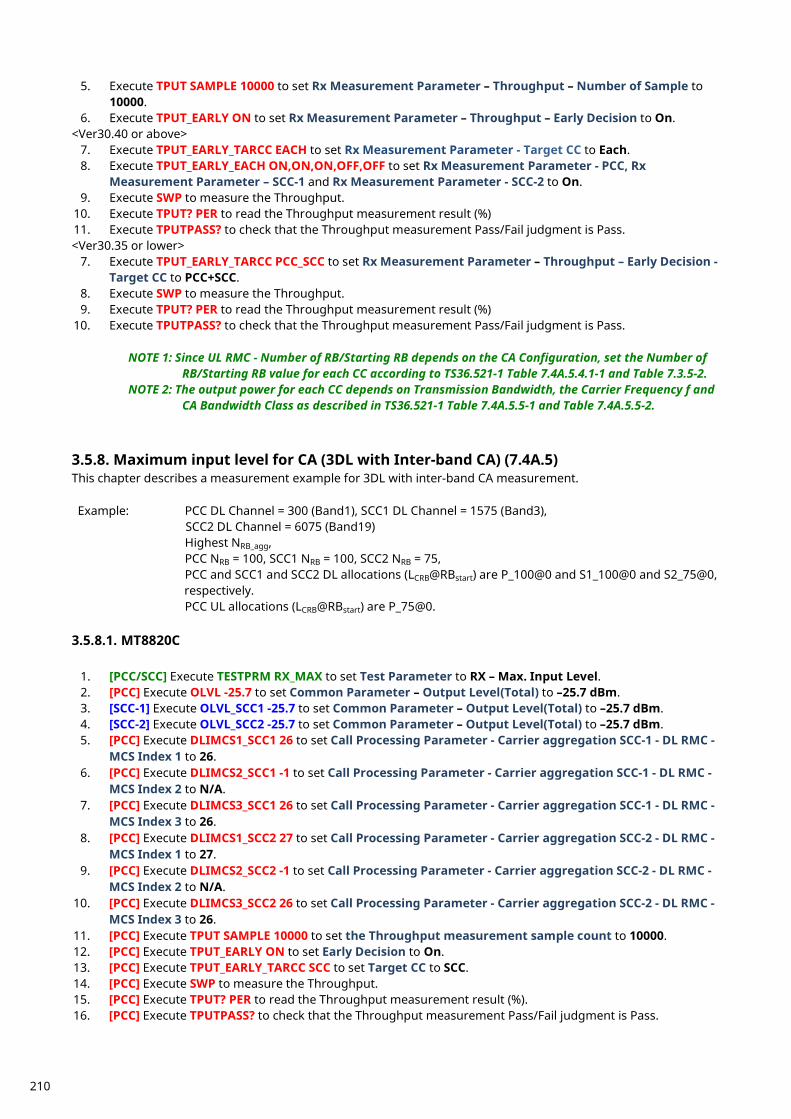
5. Execute TPUT SAMPLE 10000 to set Rx Measurement Parameter – Throughput – Number of Sample to 10000.
6. Execute TPUT_EARLY ON to set Rx Measurement Parameter – Throughput – Early Decision to On. <Ver30.40 or above>
7. Execute TPUT_EARLY_TARCC EACH to set Rx Measurement Parameter - Target CC to Each. 8. Execute TPUT_EARLY_EACH ON,ON,ON,OFF,OFF to set Rx Measurement Parameter - PCC, Rx
Measurement Parameter – SCC-1 and Rx Measurement Parameter - SCC-2 to On. 9. Execute SWP to measure the Throughput.
10. Execute TPUT? PER to read the Throughput measurement result (%) 11. Execute TPUTPASS? to check that the Throughput measurement Pass/Fail judgment is Pass. <Ver30.35 or lower>
7. Execute TPUT_EARLY_TARCC PCC_SCC to set Rx Measurement Parameter – Throughput – Early Decision - Target CC to PCC+SCC.
8. Execute SWP to measure the Throughput. 9. Execute TPUT? PER to read the Throughput measurement result (%)
10. Execute TPUTPASS? to check that the Throughput measurement Pass/Fail judgment is Pass.
NOTE 1: Since UL RMC - Number of RB/Starting RB depends on the CA Configuration, set the Number of RB/Starting RB value for each CC according to TS36.521-1 Table 7.4A.5.4.1-1 and Table 7.3.5-2.
NOTE 2: The output power for each CC depends on Transmission Bandwidth, the Carrier Frequency f and CA Bandwidth Class as described in TS36.521-1 Table 7.4A.5.5-1 and Table 7.4A.5.5-2.
Maximum input level for CA (3DL with Inter-band CA) (7.4A.5) 3.5.8.This chapter describes a measurement example for 3DL with inter-band CA measurement. Example: PCC DL Channel = 300 (Band1), SCC1 DL Channel = 1575 (Band3),
SCC2 DL Channel = 6075 (Band19) Highest NRB_agg, PCC NRB = 100, SCC1 NRB = 100, SCC2 NRB = 75, PCC and SCC1 and SCC2 DL allocations (LCRB@RBstart) are P_100@0 and S1_100@0 and S2_75@0, respectively. PCC UL allocations (LCRB@RBstart) are P_75@0.
3.5.8.1. MT8820C
1. [PCC/SCC] Execute TESTPRM RX_MAX to set Test Parameter to RX – Max. Input Level. 2. [PCC] Execute OLVL -25.7 to set Common Parameter – Output Level(Total) to –25.7 dBm. 3. [SCC-1] Execute OLVL_SCC1 -25.7 to set Common Parameter – Output Level(Total) to –25.7 dBm. 4. [SCC-2] Execute OLVL_SCC2 -25.7 to set Common Parameter – Output Level(Total) to –25.7 dBm. 5. [PCC] Execute DLIMCS1_SCC1 26 to set Call Processing Parameter - Carrier aggregation SCC-1 - DL RMC -
MCS Index 1 to 26. 6. [PCC] Execute DLIMCS2_SCC1 -1 to set Call Processing Parameter - Carrier aggregation SCC-1 - DL RMC -
MCS Index 2 to N/A. 7. [PCC] Execute DLIMCS3_SCC1 26 to set Call Processing Parameter - Carrier aggregation SCC-1 - DL RMC -
MCS Index 3 to 26. 8. [PCC] Execute DLIMCS1_SCC2 27 to set Call Processing Parameter - Carrier aggregation SCC-2 - DL RMC -
MCS Index 1 to 27. 9. [PCC] Execute DLIMCS2_SCC2 -1 to set Call Processing Parameter - Carrier aggregation SCC-2 - DL RMC -
MCS Index 2 to N/A. 10. [PCC] Execute DLIMCS3_SCC2 26 to set Call Processing Parameter - Carrier aggregation SCC-2 - DL RMC -
MCS Index 3 to 26. 11. [PCC] Execute TPUT SAMPLE 10000 to set the Throughput measurement sample count to 10000. 12. [PCC] Execute TPUT_EARLY ON to set Early Decision to On. 13. [PCC] Execute TPUT_EARLY_TARCC SCC to set Target CC to SCC. 14. [PCC] Execute SWP to measure the Throughput. 15. [PCC] Execute TPUT? PER to read the Throughput measurement result (%). 16. [PCC] Execute TPUTPASS? to check that the Throughput measurement Pass/Fail judgment is Pass.
210
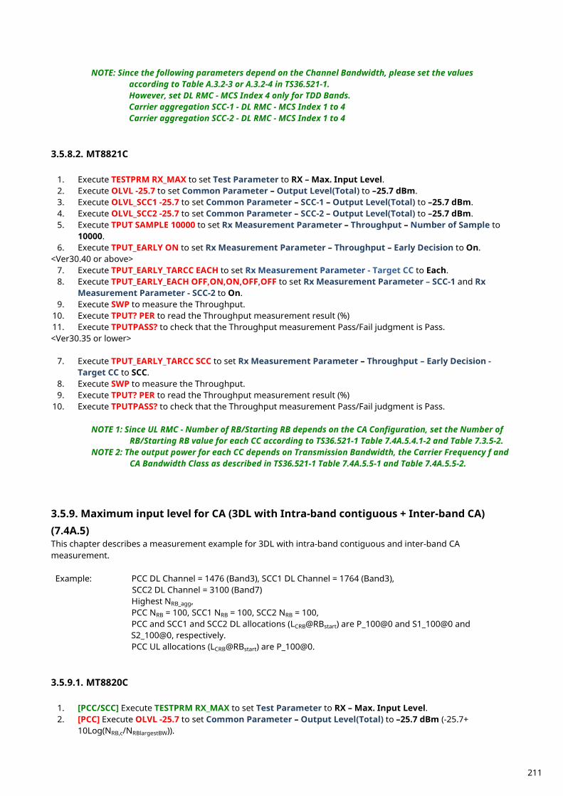
NOTE: Since the following parameters depend on the Channel Bandwidth, please set the values
according to Table A.3.2-3 or A.3.2-4 in TS36.521-1. However, set DL RMC - MCS Index 4 only for TDD Bands. Carrier aggregation SCC-1 - DL RMC - MCS Index 1 to 4 Carrier aggregation SCC-2 - DL RMC - MCS Index 1 to 4
3.5.8.2. MT8821C
1. Execute TESTPRM RX_MAX to set Test Parameter to RX – Max. Input Level. 2. Execute OLVL -25.7 to set Common Parameter – Output Level(Total) to –25.7 dBm. 3. Execute OLVL_SCC1 -25.7 to set Common Parameter – SCC-1 – Output Level(Total) to –25.7 dBm. 4. Execute OLVL_SCC2 -25.7 to set Common Parameter – SCC-2 – Output Level(Total) to –25.7 dBm. 5. Execute TPUT SAMPLE 10000 to set Rx Measurement Parameter – Throughput – Number of Sample to
10000. 6. Execute TPUT_EARLY ON to set Rx Measurement Parameter – Throughput – Early Decision to On.
<Ver30.40 or above> 7. Execute TPUT_EARLY_TARCC EACH to set Rx Measurement Parameter - Target CC to Each. 8. Execute TPUT_EARLY_EACH OFF,ON,ON,OFF,OFF to set Rx Measurement Parameter – SCC-1 and Rx
Measurement Parameter - SCC-2 to On. 9. Execute SWP to measure the Throughput.
10. Execute TPUT? PER to read the Throughput measurement result (%) 11. Execute TPUTPASS? to check that the Throughput measurement Pass/Fail judgment is Pass. <Ver30.35 or lower>
7. Execute TPUT_EARLY_TARCC SCC to set Rx Measurement Parameter – Throughput – Early Decision - Target CC to SCC.
8. Execute SWP to measure the Throughput. 9. Execute TPUT? PER to read the Throughput measurement result (%)
10. Execute TPUTPASS? to check that the Throughput measurement Pass/Fail judgment is Pass.
NOTE 1: Since UL RMC - Number of RB/Starting RB depends on the CA Configuration, set the Number of RB/Starting RB value for each CC according to TS36.521-1 Table 7.4A.5.4.1-2 and Table 7.3.5-2.
NOTE 2: The output power for each CC depends on Transmission Bandwidth, the Carrier Frequency f and CA Bandwidth Class as described in TS36.521-1 Table 7.4A.5.5-1 and Table 7.4A.5.5-2.
Maximum input level for CA (3DL with Intra-band contiguous + Inter-band CA) 3.5.9.(7.4A.5) This chapter describes a measurement example for 3DL with intra-band contiguous and inter-band CA measurement. Example: PCC DL Channel = 1476 (Band3), SCC1 DL Channel = 1764 (Band3),
SCC2 DL Channel = 3100 (Band7) Highest NRB_agg, PCC NRB = 100, SCC1 NRB = 100, SCC2 NRB = 100, PCC and SCC1 and SCC2 DL allocations (LCRB@RBstart) are P_100@0 and S1_100@0 and S2_100@0, respectively. PCC UL allocations (LCRB@RBstart) are P_100@0.
3.5.9.1. MT8820C
1. [PCC/SCC] Execute TESTPRM RX_MAX to set Test Parameter to RX – Max. Input Level. 2. [PCC] Execute OLVL -25.7 to set Common Parameter – Output Level(Total) to –25.7 dBm (-25.7+
10Log(NRB,c/NRBlargestBW)).
211
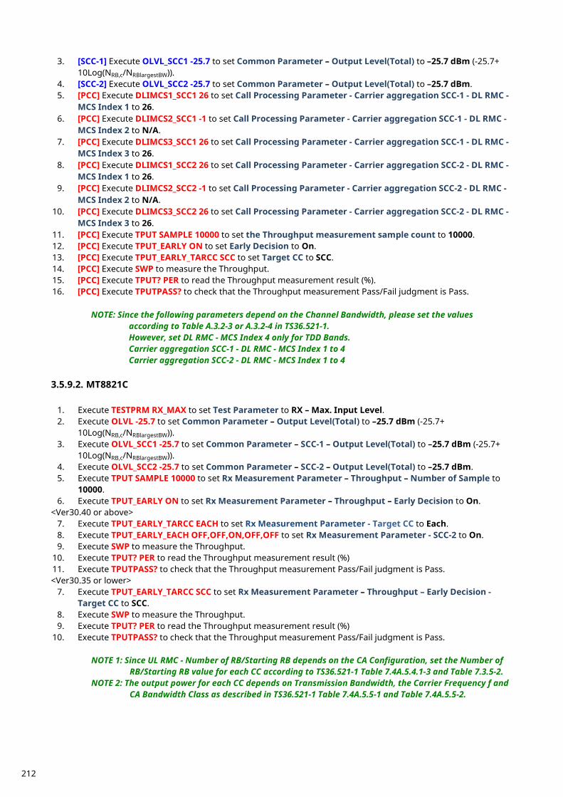
3. [SCC-1] Execute OLVL_SCC1 -25.7 to set Common Parameter – Output Level(Total) to –25.7 dBm (-25.7+ 10Log(NRB,c/NRBlargestBW)).
4. [SCC-2] Execute OLVL_SCC2 -25.7 to set Common Parameter – Output Level(Total) to –25.7 dBm. 5. [PCC] Execute DLIMCS1_SCC1 26 to set Call Processing Parameter - Carrier aggregation SCC-1 - DL RMC -
MCS Index 1 to 26. 6. [PCC] Execute DLIMCS2_SCC1 -1 to set Call Processing Parameter - Carrier aggregation SCC-1 - DL RMC -
MCS Index 2 to N/A. 7. [PCC] Execute DLIMCS3_SCC1 26 to set Call Processing Parameter - Carrier aggregation SCC-1 - DL RMC -
MCS Index 3 to 26. 8. [PCC] Execute DLIMCS1_SCC2 26 to set Call Processing Parameter - Carrier aggregation SCC-2 - DL RMC -
MCS Index 1 to 26. 9. [PCC] Execute DLIMCS2_SCC2 -1 to set Call Processing Parameter - Carrier aggregation SCC-2 - DL RMC -
MCS Index 2 to N/A. 10. [PCC] Execute DLIMCS3_SCC2 26 to set Call Processing Parameter - Carrier aggregation SCC-2 - DL RMC -
MCS Index 3 to 26. 11. [PCC] Execute TPUT SAMPLE 10000 to set the Throughput measurement sample count to 10000. 12. [PCC] Execute TPUT_EARLY ON to set Early Decision to On. 13. [PCC] Execute TPUT_EARLY_TARCC SCC to set Target CC to SCC. 14. [PCC] Execute SWP to measure the Throughput. 15. [PCC] Execute TPUT? PER to read the Throughput measurement result (%). 16. [PCC] Execute TPUTPASS? to check that the Throughput measurement Pass/Fail judgment is Pass.
NOTE: Since the following parameters depend on the Channel Bandwidth, please set the values according to Table A.3.2-3 or A.3.2-4 in TS36.521-1. However, set DL RMC - MCS Index 4 only for TDD Bands. Carrier aggregation SCC-1 - DL RMC - MCS Index 1 to 4 Carrier aggregation SCC-2 - DL RMC - MCS Index 1 to 4
3.5.9.2. MT8821C
1. Execute TESTPRM RX_MAX to set Test Parameter to RX – Max. Input Level. 2. Execute OLVL -25.7 to set Common Parameter – Output Level(Total) to –25.7 dBm (-25.7+
10Log(NRB,c/NRBlargestBW)). 3. Execute OLVL_SCC1 -25.7 to set Common Parameter – SCC-1 – Output Level(Total) to –25.7 dBm (-25.7+
10Log(NRB,c/NRBlargestBW)). 4. Execute OLVL_SCC2 -25.7 to set Common Parameter – SCC-2 – Output Level(Total) to –25.7 dBm. 5. Execute TPUT SAMPLE 10000 to set Rx Measurement Parameter – Throughput – Number of Sample to
10000. 6. Execute TPUT_EARLY ON to set Rx Measurement Parameter – Throughput – Early Decision to On.
<Ver30.40 or above> 7. Execute TPUT_EARLY_TARCC EACH to set Rx Measurement Parameter - Target CC to Each. 8. Execute TPUT_EARLY_EACH OFF,OFF,ON,OFF,OFF to set Rx Measurement Parameter - SCC-2 to On. 9. Execute SWP to measure the Throughput.
10. Execute TPUT? PER to read the Throughput measurement result (%) 11. Execute TPUTPASS? to check that the Throughput measurement Pass/Fail judgment is Pass. <Ver30.35 or lower>
7. Execute TPUT_EARLY_TARCC SCC to set Rx Measurement Parameter – Throughput – Early Decision - Target CC to SCC.
8. Execute SWP to measure the Throughput. 9. Execute TPUT? PER to read the Throughput measurement result (%)
10. Execute TPUTPASS? to check that the Throughput measurement Pass/Fail judgment is Pass.
NOTE 1: Since UL RMC - Number of RB/Starting RB depends on the CA Configuration, set the Number of RB/Starting RB value for each CC according to TS36.521-1 Table 7.4A.5.4.1-3 and Table 7.3.5-2.
NOTE 2: The output power for each CC depends on Transmission Bandwidth, the Carrier Frequency f and CA Bandwidth Class as described in TS36.521-1 Table 7.4A.5.5-1 and Table 7.4A.5.5-2.
212
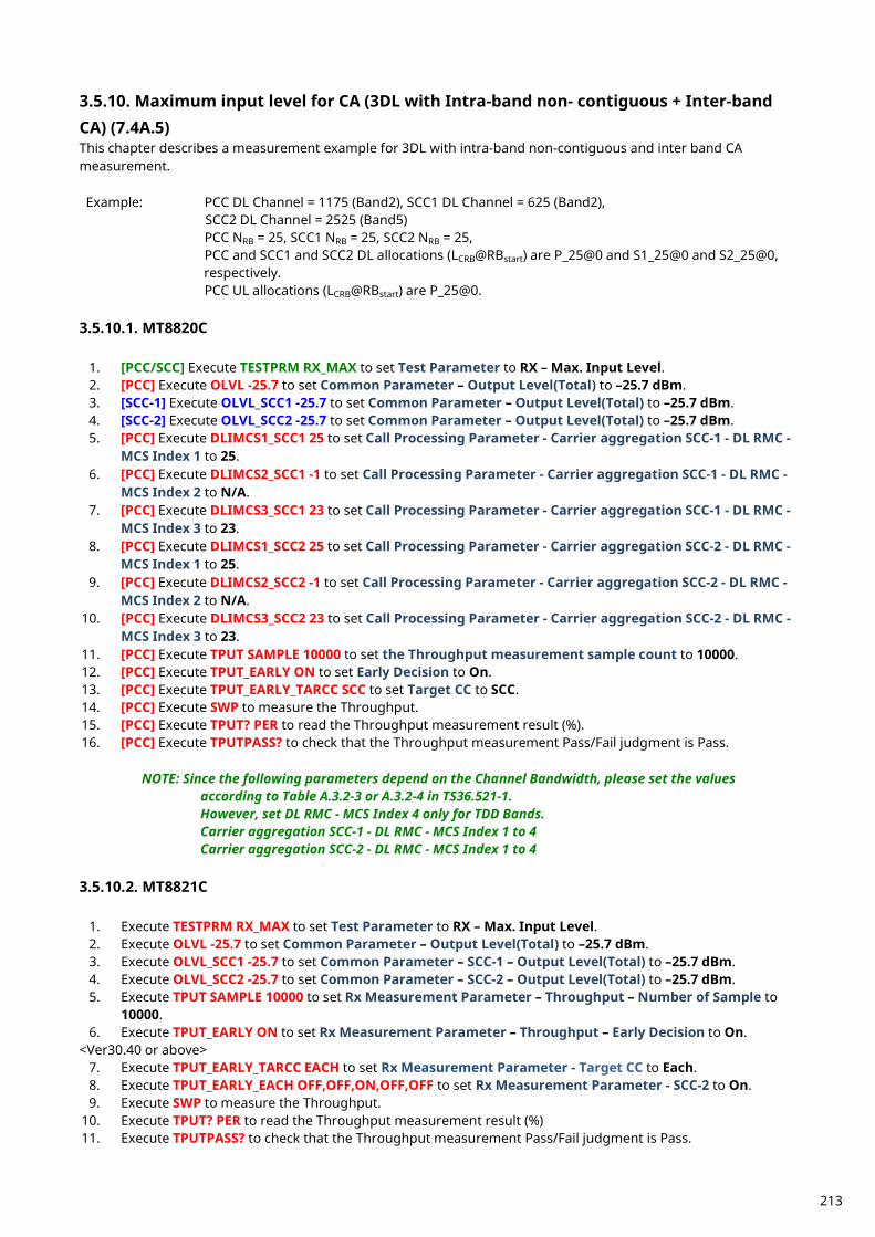
Maximum input level for CA (3DL with Intra-band non- contiguous + Inter-band 3.5.10.CA) (7.4A.5) This chapter describes a measurement example for 3DL with intra-band non-contiguous and inter band CA measurement. Example: PCC DL Channel = 1175 (Band2), SCC1 DL Channel = 625 (Band2),
SCC2 DL Channel = 2525 (Band5) PCC NRB = 25, SCC1 NRB = 25, SCC2 NRB = 25, PCC and SCC1 and SCC2 DL allocations (LCRB@RBstart) are P_25@0 and S1_25@0 and S2_25@0, respectively. PCC UL allocations (LCRB@RBstart) are P_25@0.
3.5.10.1. MT8820C
1. [PCC/SCC] Execute TESTPRM RX_MAX to set Test Parameter to RX – Max. Input Level. 2. [PCC] Execute OLVL -25.7 to set Common Parameter – Output Level(Total) to –25.7 dBm. 3. [SCC-1] Execute OLVL_SCC1 -25.7 to set Common Parameter – Output Level(Total) to –25.7 dBm. 4. [SCC-2] Execute OLVL_SCC2 -25.7 to set Common Parameter – Output Level(Total) to –25.7 dBm. 5. [PCC] Execute DLIMCS1_SCC1 25 to set Call Processing Parameter - Carrier aggregation SCC-1 - DL RMC -
MCS Index 1 to 25. 6. [PCC] Execute DLIMCS2_SCC1 -1 to set Call Processing Parameter - Carrier aggregation SCC-1 - DL RMC -
MCS Index 2 to N/A. 7. [PCC] Execute DLIMCS3_SCC1 23 to set Call Processing Parameter - Carrier aggregation SCC-1 - DL RMC -
MCS Index 3 to 23. 8. [PCC] Execute DLIMCS1_SCC2 25 to set Call Processing Parameter - Carrier aggregation SCC-2 - DL RMC -
MCS Index 1 to 25. 9. [PCC] Execute DLIMCS2_SCC2 -1 to set Call Processing Parameter - Carrier aggregation SCC-2 - DL RMC -
MCS Index 2 to N/A. 10. [PCC] Execute DLIMCS3_SCC2 23 to set Call Processing Parameter - Carrier aggregation SCC-2 - DL RMC -
MCS Index 3 to 23. 11. [PCC] Execute TPUT SAMPLE 10000 to set the Throughput measurement sample count to 10000. 12. [PCC] Execute TPUT_EARLY ON to set Early Decision to On. 13. [PCC] Execute TPUT_EARLY_TARCC SCC to set Target CC to SCC. 14. [PCC] Execute SWP to measure the Throughput. 15. [PCC] Execute TPUT? PER to read the Throughput measurement result (%). 16. [PCC] Execute TPUTPASS? to check that the Throughput measurement Pass/Fail judgment is Pass.
NOTE: Since the following parameters depend on the Channel Bandwidth, please set the values according to Table A.3.2-3 or A.3.2-4 in TS36.521-1. However, set DL RMC - MCS Index 4 only for TDD Bands. Carrier aggregation SCC-1 - DL RMC - MCS Index 1 to 4 Carrier aggregation SCC-2 - DL RMC - MCS Index 1 to 4
3.5.10.2. MT8821C
1. Execute TESTPRM RX_MAX to set Test Parameter to RX – Max. Input Level. 2. Execute OLVL -25.7 to set Common Parameter – Output Level(Total) to –25.7 dBm. 3. Execute OLVL_SCC1 -25.7 to set Common Parameter – SCC-1 – Output Level(Total) to –25.7 dBm. 4. Execute OLVL_SCC2 -25.7 to set Common Parameter – SCC-2 – Output Level(Total) to –25.7 dBm. 5. Execute TPUT SAMPLE 10000 to set Rx Measurement Parameter – Throughput – Number of Sample to
10000. 6. Execute TPUT_EARLY ON to set Rx Measurement Parameter – Throughput – Early Decision to On.
<Ver30.40 or above> 7. Execute TPUT_EARLY_TARCC EACH to set Rx Measurement Parameter - Target CC to Each. 8. Execute TPUT_EARLY_EACH OFF,OFF,ON,OFF,OFF to set Rx Measurement Parameter - SCC-2 to On. 9. Execute SWP to measure the Throughput.
10. Execute TPUT? PER to read the Throughput measurement result (%) 11. Execute TPUTPASS? to check that the Throughput measurement Pass/Fail judgment is Pass.
213
<Ver30.35 or lower> 7. Execute TPUT_EARLY_TARCC SCC to set Rx Measurement Parameter – Throughput – Early Decision -
Target CC to SCC. 8. Execute SWP to measure the Throughput. 9. Execute TPUT? PER to read the Throughput measurement result (%)
10. Execute TPUTPASS? to check that the Throughput measurement Pass/Fail judgment is Pass.
NOTE 1: Since UL RMC - Number of RB/Starting RB depends on the CA Configuration, set the Number of RB/Starting RB value for each CC according to TS36.521-1 Table 7.4A.5.4.1-4 and Table 7.3.5-2.
NOTE 2: The output power for each CC depends on Transmission Bandwidth, the Carrier Frequency f and CA Bandwidth Class as described in TS36.521-1 Table 7.4A.5.5-1 and Table 7.4A.5.5-2.
Maximum input level for CA (3DL with Intra-band non- contiguous + Intra-band 3.5.11.CA) (7.4A.5) This chapter describes a measurement example for 3DL with intra-band non-contiguous and inter band CA measurement. Example: PCC DL Channel = 41490 (Band41), SCC1 DL Channel = 41292 (Band41),
SCC2 DL Channel = 39750 (Band41) PCC NRB = 100, SCC1 NRB = 100, SCC2 NRB = 100, PCC and SCC1 and SCC2 DL allocations (LCRB@RBstart) are P_100@0 and S1_100@0 and S2_100@0, respectively. PCC UL allocations (LCRB@RBstart) are P_100@0.
3.5.11.1. MT8820C
1. [PCC/SCC] Execute TESTPRM RX_MAX to set Test Parameter to RX – Max. Input Level. 2. [PCC] Execute OLVL -25.7 to set Common Parameter – Output Level(Total) to –25.7 dBm (-25.7+
10Log(NRB,c/NRBlargestBW)). 3. [SCC-1] Execute OLVL_SCC1 -25.7 to set Common Parameter – Output Level(Total) to –25.7 dBm (-25.7+
10Log(NRB,c/NRBlargestBW)). 4. [SCC-2] Execute OLVL_SCC2 -25.7 to set Common Parameter – Output Level(Total) to –25.7 dBm. 5. [PCC] Execute DLIMCS1_SCC1 26 to set Call Processing Parameter - Carrier aggregation SCC-1 - DL RMC -
MCS Index 1 to 26. 6. [PCC] Execute DLIMCS2_SCC1 -1 to set Call Processing Parameter - Carrier aggregation SCC-1 - DL RMC -
MCS Index 2 to N/A. 7. [PCC] Execute DLIMCS3_SCC1 26 to set Call Processing Parameter - Carrier aggregation SCC-1 - DL RMC -
MCS Index 3 to 26. 8. [PCC] Execute DLIMCS4_SCC1 27 to set Call Processing Parameter - Carrier aggregation SCC-1 - DL RMC -
MCS Index 4 to 27. 9. [PCC] Execute DLIMCS1_SCC2 26 to set Call Processing Parameter - Carrier aggregation SCC-2 - DL RMC -
MCS Index 1 to 26. 10. [PCC] Execute DLIMCS2_SCC2 -1 to set Call Processing Parameter - Carrier aggregation SCC-2 - DL RMC -
MCS Index 2 to N/A. 11. [PCC] Execute DLIMCS3_SCC2 26 to set Call Processing Parameter - Carrier aggregation SCC-2 - DL RMC -
MCS Index 3 to 26. 12. [PCC] Execute DLIMCS4_SCC2 27 to set Call Processing Parameter - Carrier aggregation SCC-2 - DL RMC -
MCS Index 4 to 27. 13. [PCC] Execute TPUT SAMPLE 10000 to set the Throughput measurement sample count to 10000. 14. [PCC] Execute TPUT_EARLY ON to set Early Decision to On. 15. [PCC] Execute TPUT_EARLY_TARCC PCC_SCC to set Target CC to PCC+SCC. 16. [PCC] Execute SWP to measure the Throughput. 17. [PCC] Execute TPUT? PER to read the Throughput measurement result (%). 18. [PCC] Execute TPUTPASS? to check that the Throughput measurement Pass/Fail judgment is Pass.
NOTE: Since the following parameters depend on the Channel Bandwidth, please set the values according to Table A.3.2-3 or A.3.2-4 in TS36.521-1.
214
However, set DL RMC - MCS Index 4 only for TDD Bands. Carrier aggregation SCC-1 - DL RMC - MCS Index 1 to 4 Carrier aggregation SCC-2 - DL RMC - MCS Index 1 to 4
3.5.11.2. MT8821C
1. Execute TESTPRM RX_MAX to set Test Parameter to RX – Max. Input Level. 2. Execute OLVL -25.7 to set Common Parameter – Output Level(Total) to –25.7 dBm (-25.7+
10Log(NRB,c/NRBlargestBW)). 3. Execute OLVL_SCC1 -25.7 to set Common Parameter – SCC-1 – Output Level(Total) to –25.7 dBm (-25.7+
10Log(NRB,c/NRBlargestBW)). 4. Execute OLVL_SCC2 -25.7 to set Common Parameter – SCC-2 – Output Level(Total) to –25.7 dBm. 5. Execute TPUT SAMPLE 10000 to set Rx Measurement Parameter – Throughput – Number of Sample to
10000. 6. Execute TPUT_EARLY ON to set Rx Measurement Parameter – Throughput – Early Decision to On.
<Ver30.40 or above> 7. Execute TPUT_EARLY_TARCC EACH to set Rx Measurement Parameter - Target CC to Each. 8. Execute TPUT_EARLY_EACH ON,ON,ON,OFF,OFF to set Rx Measurement Parameter - PCC, Rx
Measurement Parameter – SCC-1 and Rx Measurement Parameter - SCC-2 to On. 9. Execute SWP to measure the Throughput.
10. Execute TPUT? PER to read the Throughput measurement result (%) 11. Execute TPUTPASS? to check that the Throughput measurement Pass/Fail judgment is Pass. <Ver30.35 or lower>
7. Execute TPUT_EARLY_TARCC PCC_SCC to set Rx Measurement Parameter – Throughput – Early Decision - Target CC to PCC+SCC.
8. Execute SWP to measure the Throughput. 9. Execute TPUT? PER to read the Throughput measurement result (%)
10. Execute TPUTPASS? to check that the Throughput measurement Pass/Fail judgment is Pass.
NOTE 1: Since UL RMC - Number of RB/Starting RB depends on the CA Configuration, set the Number of RB/Starting RB value for each CC according to TS36.521-1 Table 7.4A.5.4.1-5 and Table 7.3.5-2.
NOTE 2: The output power for each CC depends on Transmission Bandwidth and the Carrier Frequency f and CA Bandwidth Class as described in TS36.521-1 Table 7.4A.5.5-1 and Table 7.4A.5.5-2.
Maximum input level for CA (3DL with Intra-band contiguous CA) for 256QAM in 3.5.12.DL (7.4A.5_H) (MT8821C Only)
The test condition is same as chapter3.5.7.
1. Execute DLRMC_256QAM to set DL RMC – 256QAM to Enabled. 2. Execute TESTPRM RX_MAX to set Test Parameter to RX – Max. Input Level. 3. Execute OLVL -30.7 to set Common Parameter - Output Level to -30.7dBm (-27.7+ 10Log(NRB,c/NRBlargestBW)). 4. Execute OLVL_SCC1 -27.7 to set Common Parameter – SCC-1 – Output Level(Total) to –27.7 dBm (-27.7+
10Log(NRB,c/NRBlargestBW)). 5. Execute OLVL_SCC1 -28.9 to set Common Parameter – SCC-1 – Output Level(Total) to –28.9 dBm (-27.7+
10Log(NRB,c/NRBlargestBW)). 6. Execute TPUT_SAMPLE 10000 to set Rx Measurement Parameter – Throughput – Number of Sample to
10000. 7. Execute TPUT_EARLY ON to set Rx Measurement Parameter – Throughput – Early Decision to On.
<Ver30.40 or above> 8. Execute TPUT_EARLY_TARCC EACH to set Rx Measurement Parameter - Target CC to Each. 9. Execute TPUT_EARLY_EACH ON,ON,ON,OFF,OFF to set Rx Measurement Parameter - PCC, Rx
Measurement Parameter – SCC-1 and Rx Measurement Parameter - SCC-2 to On. 10. Execute SWP to measure the Throughput. 11. Execute TPUT? PER to read the Throughput measurement result (%). 12. Execute TPUTPASS? to check that the Throughput measurement Pass/Fail judgment is Pass.
215
<Ver30.35 or lower> 8. Execute TPUT_EARLY_TARCC PCC_SCC to set Rx Measurement Parameter – Throughput – Early Decision -
Target CC to PCC+SCC. 9. Execute SWP to measure the Throughput.
10. Execute TPUT? PER to read the Throughput measurement result (%). 11. Execute TPUTPASS? to check that the Throughput measurement Pass/Fail judgment is Pass.
NOTE 1: Since UL RMC - Number of RB/Starting RB depends on the CA Configuration, set the Number of RB/Starting RB value for each CC according to TS36.521-1 Table 7.4A.5_H.4.1-1 and Table 7.3.5-2.
NOTE 2: The output power for each CC depends on the Transmission Bandwidth and the Carrier
Frequency f as described in TS36.521–1 Table 7.4A.5.H.5-1.
Maximum input level for CA (3DL with Inter-band CA) for 256QAM in DL (7.4A.5_H) 3.5.13.(MT8821C Only)
The test condition is same as chapter3.5.8.
1. Execute DLRMC_256QAM to set DL RMC – 256QAM to Enabled. 2. Execute TESTPRM RX_MAX to set Test Parameter to RX – Max. Input Level. 3. Execute OLVL_-27.7 to set Output Level(Total) to -27.7 dBm. 4. Execute OLVL_SCC1 -27.7 to set SCC-1 - Output Level(Total) to -27.7 dBm. 5. Execute OLVL_SCC2 -27.7 to set SCC-2 - Output Level(Total) to -27.7 dBm. 6. Execute TPUT_SAMPLE 10000 to set Rx Measurement Parameter – Throughput – Number of Sample to
10000. 7. Execute TPUT_EARLY ON to set Rx Measurement Parameter – Throughput – Early Decision to On.
<Ver30.40 or above> 8. Execute TPUT_EARLY_TARCC EACH to set Rx Measurement Parameter - Target CC to Each. 9. Execute TPUT_EARLY_EACH OFF,ON,ON,OFF,OFF to set Rx Measurement Parameter – SCC-1 and Rx
Measurement Parameter - SCC-2 to On. 10. Execute SWP to measure the Throughput. 11. Execute TPUT? PER to read the Throughput measurement result (%). 12. Execute TPUTPASS? to check that the Throughput measurement Pass/Fail judgment is Pass. <Ver30.35 or lower>
8. Execute TPUT_EARLY_TARCC SCC to set Rx Measurement Parameter – Throughput – Early Decision - Target CC to SCC.
9. Execute SWP to measure the Throughput. 10. Execute TPUT? PER to read the Throughput measurement result (%). 11. Execute TPUTPASS? to check that the Throughput measurement Pass/Fail judgment is Pass.
NOTE 1: Since UL RMC - Number of RB/Starting RB depends on the CA Configuration, set the Number of RB/Starting RB value for each CC according to TS36.521-1 Table 7.4A.5_H.4.1-2 and Table 7.3.5-2.
NOTE 2: The output power for each CC depends on the Carrier Frequency f as described in TS36.521–1
Table 7.4A.5.H.5-2.
Maximum input level for CA (3DL with Intra-band contiguous + Inter-band CA) for 3.5.14.256QAM in DL (7.4A.5_H) (MT8821C Only)
The test condition is same as chapter3.5.9.
1. Execute DLRMC_256QAM to set DL RMC – 256QAM to Enabled. 2. Execute TESTPRM RX_MAX to set Test Parameter to RX – Max. Input Level. 3. Execute OLVL_-27.7 to set Output Level(Total) to -27.7 dBm. 4. Execute OLVL_SCC1 -27.7 to set SCC-1 - Output Level(Total) to -27.7 dBm. 5. Execute OLVL_SCC2 -27.7 to set SCC-2 - Output Level(Total) to -27.7 dBm.
216
<Ver30.40 or above> 6. Execute TPUT_SAMPLE 10000 to set Rx Measurement Parameter – Throughput – Number of Sample to
10000. 7. Execute TPUT_EARLY ON to set Rx Measurement Parameter – Throughput – Early Decision to On. 8. Execute TPUT_EARLY_TARCC EACH to set Rx Measurement Parameter - Target CC to Each. 9. Execute TPUT_EARLY_EACH OFF,OFF,ON,OFF,OFF to set Rx Measurement Parameter – SCC2 to On.
10. Execute SWP to measure the Throughput. 11. Execute TPUT? PER to read the Throughput measurement result (%). 12. Execute TPUTPASS? to check that the Throughput measurement Pass/Fail judgment is Pass. <Ver30.35 or lower>
6. Execute TPUT_SAMPLE 1003 to set Rx Measurement Parameter – Throughput – Number of Sample to 1003.
7. Execute SWP to measure the Throughput. Ignore Pass/Fail judgment. 8. Execute TPUT_BLERCNTNACK? SCC2 to confirm the SCC2 Error Count (NACK). This test is to pass judgment if
the Error Count is 62 or less.
NOTE 1: Since UL RMC - Number of RB/Starting RB depends on the CA Configuration, set the Number of RB/Starting RB value for each CC according to TS36.521-1 Table 7.4A.5_H.4.1-3 and Table 7.3.5-2.
NOTE 2: The output power for each CC depends on Transmission Bandwidth and the Carrier Frequency f
and CA Bandwidth Class as described in TS36.521–1 Table 7.4A.5_H.5-1 and Table 7.4A.5.H5-2. NOTE 3: Since the CC measurement target differs according to the Test Configuration ID, measure the CC described in TS36.521-1 Table 7.4A.5_H.4.2-1. NOTE 4: Refer to the measurement result as a guide. The Reason for the measurement Number of
Samples is not exactly 1003 in Ver30.33 or lower, and so the measurement results are not accurate.
Maximum input level for CA (3DL with Intra-band non-contiguous + Inter-band 3.5.15.CA) for 256QAM in DL (7.4A.5_H) (MT8821C Only)
The test condition is same as chapter3.5.10.
1. Execute DLRMC_256QAM to set DL RMC – 256QAM to Enabled. 2. Execute TESTPRM RX_MAX to set Test Parameter to RX – Max. Input Level. 3. Execute OLVL_-27.7 to set Output Level(Total) to -27.7 dBm. 4. Execute OLVL_SCC1 -27.7 to set SCC-1 - Output Level(Total) to -27.7 dBm. 5. Execute OLVL_SCC2 -27.7 to set SCC-2 - Output Level(Total) to -27.7 dBm.
<Ver30.40 or above> 6. Execute TPUT_SAMPLE 10000 to set Rx Measurement Parameter – Throughput – Number of Sample to
10000. 7. Execute TPUT_EARLY ON to set Rx Measurement Parameter – Throughput – Early Decision to On. 8. Execute TPUT_EARLY_TARCC EACH to set Rx Measurement Parameter - Target CC to Each. 9. Execute TPUT_EARLY_EACH OFF,OFF,ON,OFF,OFF to set Rx Measurement Parameter – SCC2 to On.
10. Execute SWP to measure the Throughput. 11. Execute TPUT? PER to read the Throughput measurement result (%). 12. Execute TPUTPASS? to check that the Throughput measurement Pass/Fail judgment is Pass. <Ver30.35 or lower>
6. Execute TPUT_SAMPLE 1003 to set Rx Measurement Parameter – Throughput – Number of Sample to 1003.
7. Execute SWP to measure the Throughput. Ignore Pass/Fail judgment. 8. Execute TPUT_BLERCNTNACK? SCC2 to confirm the SCC2 Error Count (NACK). This test is to pass judgment if
the Error Count is 62 or less.
NOTE 1: Since UL RMC - Number of RB/Starting RB depends on the CA Configuration, set the Number of RB/Starting RB value for each CC according to TS36.521-1 Table 7.4A.5_H.4.1-4 and Table 7.3.5-2.
NOTE 2: The output power for each CC depends on the Carrier Frequency f as described in TS36.521–1
Table 7.4A.5.H.5-2.
217
NOTE 3: Since the CC measurement target differs according to the Test Configuration ID, measure the CC described in TS36.521-1 Table 7.4A.5_H.4.2-1.
NOTE 4: Refer to the measurement result as a guide. The Reason for the measurement Number of
Samples is not exactly 1003 in Ver30.33 or lower, and so the measurement results are not accurate.
Maximum input level for CA (3DL with Intra-band non-contiguous + Intra-band 3.5.16.contiguous CA) for 256QAM in DL (7.4A.5_H) (MT8821C Only)
The test condition is same as chapter3.5.11.
1. Execute DLRMC_256QAM to set DL RMC – 256QAM to Enabled. 2. Execute TESTPRM RX_MAX to set Test Parameter to RX – Max. Input Level. 3. Execute OLVL_-27.7 to set Output Level(Total) to -27.7 dBm. 4. Execute OLVL_SCC1 -27.7 to set SCC-1 - Output Level(Total) to -27.7 dBm. 5. Execute OLVL_SCC2 -27.7 to set SCC-2 - Output Level(Total) to -27.7 dBm. 6. Execute TPUT_SAMPLE 10000 to set Rx Measurement Parameter – Throughput – Number of Sample to
10000. 7. Execute TPUT_EARLY ON to set Rx Measurement Parameter – Throughput – Early Decision to On.
<Ver30.40 or above> 8. Execute TPUT_EARLY_TARCC EACH to set Rx Measurement Parameter - Target CC to Each. 9. Execute TPUT_EARLY_EACH ON,ON,ON,OFF,OFF to set Rx Measurement Parameter - PCC, Rx
Measurement Parameter – SCC-1 and Rx Measurement Parameter - SCC-2 to On. 10. Execute SWP to measure the Throughput. 11. Execute TPUT? PER to read the Throughput measurement result (%). 12. Execute TPUTPASS? to check that the Throughput measurement Pass/Fail judgment is Pass. <Ver30.35 or lower>
8. Execute TPUT_EARLY_TARCC PCC_SCC to set Rx Measurement Parameter – Throughput – Early Decision - Target CC to PCC+SCC.
9. Execute SWP to measure the Throughput. 10. Execute TPUT? PER to read the Throughput measurement result (%). 11. Execute TPUTPASS? to check that the Throughput measurement Pass/Fail judgment is Pass.
NOTE 1: Since UL RMC - Number of RB/Starting RB depends on the CA Configuration, set the Number of RB/Starting RB value fore ach CC according to TS36.521-1 Table 7.4A.5_H.4.1-5 and Table 7.3.5-2.
NOTE 2: The output power for each CC depends on Transmission Bandwidth and the Carrier Frequency f
and CA Bandwidth Class as described in TS36.521–1 Table 7.4A.5_H.5-1 and Table 7.4A.5.H5-2.
218
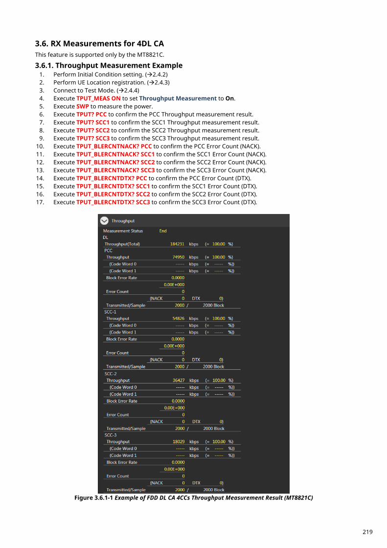
RX Measurements for 4DL CA 3.6.This feature is supported only by the MT8821C.
Throughput Measurement Example 3.6.1.1. Perform Initial Condition setting. (2.4.2) 2. Perform UE Location registration. (2.4.3) 3. Connect to Test Mode. (2.4.4) 4. Execute TPUT_MEAS ON to set Throughput Measurement to On. 5. Execute SWP to measure the power. 6. Execute TPUT? PCC to confirm the PCC Throughput measurement result. 7. Execute TPUT? SCC1 to confirm the SCC1 Throughput measurement result. 8. Execute TPUT? SCC2 to confirm the SCC2 Throughput measurement result. 9. Execute TPUT? SCC3 to confirm the SCC3 Throughput measurement result.
10. Execute TPUT_BLERCNTNACK? PCC to confirm the PCC Error Count (NACK). 11. Execute TPUT_BLERCNTNACK? SCC1 to confirm the SCC1 Error Count (NACK). 12. Execute TPUT_BLERCNTNACK? SCC2 to confirm the SCC2 Error Count (NACK). 13. Execute TPUT_BLERCNTNACK? SCC3 to confirm the SCC3 Error Count (NACK). 14. Execute TPUT_BLERCNTDTX? PCC to confirm the PCC Error Count (DTX). 15. Execute TPUT_BLERCNTDTX? SCC1 to confirm the SCC1 Error Count (DTX). 16. Execute TPUT_BLERCNTDTX? SCC2 to confirm the SCC2 Error Count (DTX). 17. Execute TPUT_BLERCNTDTX? SCC3 to confirm the SCC3 Error Count (DTX).
Figure 3.6.1-1 Example of FDD DL CA 4CCs Throughput Measurement Result (MT8821C)
219
Reference sensitivity level for CA (4DL with Intra-band contiguous CA)(7.3A.9) 3.6.2.This chapter describes a measurement example for 4DL with intra-band contiguous CA measurement. Example: PCC DL Channel = 41690 (Band42), SCC1 DL Channel = 41888 (Band42),
SCC2 DL Channel = 42086 (Band42), SCC3 DL Channel = 42284 (Band42), Highest NRB_agg, PCC NRB = 100, SCC1 NRB = 100, SCC2 NRB = 100, SCC3 NRB = 100 PCC and SCC1 and SCC2 and SCC3 DL allocations (LCRB@RBstart) are P_100@0 and S1_100@0 and S2_100@0 and S3_100@0, respectively. PCC UL allocations (LCRB@RBstart) are P_100@0.
1. Execute TESTPRM RX_SENS to set Test Parameter to RX – Ref. Sens./Freq. Error. 2. Execute TPUT SAMPLE 10000 to set Rx Measurement Parameter – Throughput – Number of Sample to
10000. 3. Execute TPUT_EARLY ON to set Rx Measurement Parameter – Throughput – Early Decision to On.
<Ver30.40 or above> 4. Execute TPUT_EARLY_TARCC EACH to set Rx Measurement Parameter – Throughput – Early Decision -
Target CC to Each. 5. Execute TPUT_EARLY_EACH ON,ON,ON,ON,OFF to set Rx Measurement Parameter – Throughput – Early
Decision - Target CC – PCC/SCC-1/SCC-2/SCC-3 to On. 6. Execute SWP to measure the Throughput. 7. Execute TPUT? PER to read the Throughput measurement result (%) 8. Execute TPUTPASS? to check that the Throughput measurement Pass/Fail judgment is Pass.
<Ver30.35 or lower> 4. Execute TPUT_EARLY_TARCC PCC_SCC to set Rx Measurement Parameter – Throughput – Early Decision -
Target CC to PCC+SCC. 5. Execute SWP to measure the Throughput. 6. Execute TPUT? PER to read the Throughput measurement result (%) 7. Execute TPUTPASS? to check that the Throughput measurement Pass/Fail judgment is Pass.
NOTE 1: Since UL RMC - Number of RB/Starting RB depends on the Operation Band, please set the
Number of RB/Starting RB value for each CC according to TS36.521-1 Table 7.3A.9.4.1-1 and Table 7.3.5-2.
Reference sensitivity level for CA (4DL with Inter-band CA)(7.3A.9) 3.6.3.This chapter describes a measurement example for 4DL with inter-band CA measurement. Example: PCC DL Channel = 900 (Band2), SCC1 DL Channel = 2175 (Band4),
SCC2 DL Channel = 2525 (Band5), SCC3 DL Channel = 9715 (Band29) PCC NRB = 100, SCC1 NRB = 100, SCC2 NRB = 50, SCC3 NRB = 50, PCC and SCC1 and SCC2 and SCC3 DL allocations (LCRB@RBstart) are P_100@0 and S1_100@0 and S2_50@0, S3_50@0 respectively. PCC UL allocations (LCRB@RBstart) are P_45@0.
1. Execute TESTPRM RX_SENS to set Test Parameter to RX – Ref. Sens./Freq. Error. 2. Execute TPUT SAMPLE 10000 to set Rx Measurement Parameter – Throughput – Number of Sample to
10000. 3. Execute TPUT_EARLY ON to set Rx Measurement Parameter – Throughput – Early Decision to On.
<Ver30.40 or above> 4. Execute TPUT_EARLY_TARCC EACH to set Rx Measurement Parameter – Throughput – Early Decision -
Target CC to Each. 5. Execute TPUT_EARLY_EACH ON,ON,ON,ON,OFF to set Rx Measurement Parameter – Throughput – Early
Decision - Target CC – PCC/SCC-1/SCC-2/SCC-3 to On. 6. Execute SWP to measure the Throughput. 7. Execute TPUT? PER to read the Throughput measurement result (%) 8. Execute TPUTPASS? to check that the Throughput measurement Pass/Fail judgment is Pass.
220
<Ver30.35 or lower> 4. Execute TPUT_EARLY_TARCC PCC_SCC to set Rx Measurement Parameter – Throughput – Early Decision -
Target CC to PCC+SCC. 5. Execute SWP to measure the Throughput. 6. Execute TPUT? PER to read the Throughput measurement result (%) 7. Execute TPUTPASS? to check that the Throughput measurement Pass/Fail judgment is Pass.
NOTE 1: Since UL RMC - Number of RB/Starting RB depends on the Operation Band, please set the
Number of RB/Starting RB value for each CC according to TS36.521-1 Table 7.3A.9.4.1-2 and Table 7.3.5-2.
NOTE 2: Set the output power for each CC according to TS36.521-1 Table 7.3A.9.5-3.
Reference sensitivity level for CA (4DL with Intra-band contiguous + Inter-band 3.6.4.CA)(7.3A.9) This chapter describes a measurement example for 4DL with Intra-band contiguous and inter-band CA measurement. Example: PCC DL Channel = 801 (Band2), SCC1 DL Channel = 999 (Band2),
SCC2 DL Channel = 9715 (Band29), SCC3 DL Channel = 9820 (Band30) Highest NRB_agg, PCC NRB = 100, SCC1 NRB = 100, SCC2 NRB = 50, SCC3 NRB = 50, PCC and SCC1 and SCC2 and SCC3 DL allocations (LCRB@RBstart) are P_100@0 and S1_100@0 and S2_50@0, S3_50@0 respectively. PCC UL allocations (LCRB@RBstart) are P_100@0.
1. Execute TESTPRM RX_SENS to set Test Parameter to RX – Ref. Sens./Freq. Error. 2. Execute TPUT SAMPLE 10000 to set Rx Measurement Parameter – Throughput – Number of Sample to
10000. 3. Execute TPUT_EARLY ON to set Rx Measurement Parameter – Throughput – Early Decision to On.
<Ver30.40 or above> 4. Execute TPUT_EARLY_TARCC EACH to set Rx Measurement Parameter – Throughput – Early Decision -
Target CC to Each. 5. Execute TPUT_EARLY_EACH ON,ON,ON,ON,OFF to set Rx Measurement Parameter – Throughput – Early
Decision - Target CC – PCC/SCC-1/SCC-2/SCC-3 to On. 6. Execute SWP to measure the Throughput. 7. Execute TPUT? PER to read the Throughput measurement result (%) 8. Execute TPUTPASS? to check that the Throughput measurement Pass/Fail judgment is Pass.
<Ver30.35 or lower> 4. Execute TPUT_EARLY_TARCC PCC_SCC to set Rx Measurement Parameter – Throughput – Early Decision -
Target CC to PCC+SCC. 5. Execute SWP to measure the Throughput. 6. Execute TPUT? PER to read the Throughput measurement result (%) 7. Execute TPUTPASS? to check that the Throughput measurement Pass/Fail judgment is Pass.
NOTE 1: Since UL RMC - Number of RB/Starting RB depends on the Operation Band, please set the
Number of RB/Starting RB value for each CC according to TS36.521-1 Table 7.3A.9.4.1-3 and Table 7.3.5-2.
NOTE 2: Set the output power for each CC according to TS36.521-1 Table 7.3A.9.5-5.
Maximum input level for CA (4DL with Intra-band contiguous CA)(7.4A.7) 3.6.5.This chapter describes a measurement example for 4DL with Intra-band contiguous CA measurement. Example: PCC DL Channel = 40896 (Band41), SCC1 DL Channel = 41094 (Band41),
SCC2 DL Channel = 41292 (Band41), SCC3 DL Channel = 41490 (Band41)
221
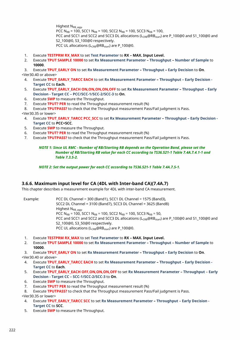
Highest NRB_agg, PCC NRB = 100, SCC1 NRB = 100, SCC2 NRB = 100, SCC3 NRB = 100, PCC and SCC1 and SCC2 and SCC3 DL allocations (LCRB@RBstart) are P_100@0 and S1_100@0 and S2_100@0, S3_100@0 respectively. PCC UL allocations (LCRB@RBstart) are P_100@0.
1. Execute TESTPRM RX_MAX to set Test Parameter to RX – MAX. Input Level. 2. Execute TPUT SAMPLE 10000 to set Rx Measurement Parameter – Throughput – Number of Sample to
10000. 3. Execute TPUT_EARLY ON to set Rx Measurement Parameter – Throughput – Early Decision to On.
<Ver30.40 or above> 4. Execute TPUT_EARLY_TARCC EACH to set Rx Measurement Parameter – Throughput – Early Decision -
Target CC to Each. 5. Execute TPUT_EARLY_EACH ON,ON,ON,ON,OFF to set Rx Measurement Parameter – Throughput – Early
Decision - Target CC – PCC/SCC-1/SCC-2/SCC-3 to On. 6. Execute SWP to measure the Throughput. 7. Execute TPUT? PER to read the Throughput measurement result (%) 8. Execute TPUTPASS? to check that the Throughput measurement Pass/Fail judgment is Pass.
<Ver30.35 or lower> 4. Execute TPUT_EARLY_TARCC PCC_SCC to set Rx Measurement Parameter – Throughput – Early Decision -
Target CC to PCC+SCC. 5. Execute SWP to measure the Throughput. 6. Execute TPUT? PER to read the Throughput measurement result (%) 7. Execute TPUTPASS? to check that the Throughput measurement Pass/Fail judgment is Pass.
NOTE 1: Since UL RMC - Number of RB/Starting RB depends on the Operation Band, please set the
Number of RB/Starting RB value for each CC according to TS36.521-1 Table 7.4A.7.4.1-1 and Table 7.3.5-2.
NOTE 2: Set the output power for each CC according to TS36.521-1 Table 7.4A.7.5-1.
Maximum input level for CA (4DL with Inter-band CA)(7.4A.7) 3.6.6.This chapter describes a measurement example for 4DL with inter-band CA measurement. Example: PCC DL Channel = 300 (Band1), SCC1 DL Channel = 1575 (Band3),
SCC2 DL Channel = 3100 (Band7), SCC3 DL Channel = 3625 (Band8) Highest NRB_agg, PCC NRB = 100, SCC1 NRB = 100, SCC2 NRB = 100, SCC3 NRB = 50, PCC and SCC1 and SCC2 and SCC3 DL allocations (LCRB@RBstart) are P_100@0 and S1_100@0 and S2_100@0, S3_50@0 respectively. PCC UL allocations (LCRB@RBstart) are P_100@0.
1. Execute TESTPRM RX_MAX to set Test Parameter to RX – MAX. Input Level. 2. Execute TPUT SAMPLE 10000 to set Rx Measurement Parameter – Throughput – Number of Sample to
10000. 3. Execute TPUT_EARLY ON to set Rx Measurement Parameter – Throughput – Early Decision to On.
<Ver30.40 or above> 4. Execute TPUT_EARLY_TARCC EACH to set Rx Measurement Parameter – Throughput – Early Decision -
Target CC to Each. 5. Execute TPUT_EARLY_EACH OFF,ON,ON,ON,OFF to set Rx Measurement Parameter – Throughput – Early
Decision - Target CC – SCC-1/SCC-2/SCC-3 to On. 6. Execute SWP to measure the Throughput. 7. Execute TPUT? PER to read the Throughput measurement result (%) 8. Execute TPUTPASS? to check that the Throughput measurement Pass/Fail judgment is Pass.
<Ver30.35 or lower> 4. Execute TPUT_EARLY_TARCC SCC to set Rx Measurement Parameter – Throughput – Early Decision -
Target CC to SCC. 5. Execute SWP to measure the Throughput.
222
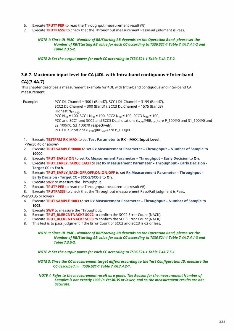
6. Execute TPUT? PER to read the Throughput measurement result (%) 7. Execute TPUTPASS? to check that the Throughput measurement Pass/Fail judgment is Pass.
NOTE 1: Since UL RMC - Number of RB/Starting RB depends on the Operation Band, please set the
Number of RB/Starting RB value for each CC according to TS36.521-1 Table 7.4A.7.4.1-2 and Table 7.3.5-2.
NOTE 2: Set the output power for each CC according to TS36.521-1 Table 7.4A.7.5-2.
Maximum input level for CA (4DL with Intra-band contiguous + Inter-band 3.6.7.CA)(7.4A.7) This chapter describes a measurement example for 4DL with Intra-band contiguous and inter-band CA measurement. Example: PCC DL Channel = 3001 (Band7), SCC1 DL Channel = 3199 (Band7),
SCC2 DL Channel = 300 (Band1), SCC3 DL Channel = 1575 (Band3) Highest NRB_agg, PCC NRB = 100, SCC1 NRB = 100, SCC2 NRB = 100, SCC3 NRB = 100, PCC and SCC1 and SCC2 and SCC3 DL allocations (LCRB@RBstart) are P_100@0 and S1_100@0 and S2_100@0, S3_100@0 respectively. PCC UL allocations (LCRB@RBstart) are P_100@0.
1. Execute TESTPRM RX_MAX to set Test Parameter to RX – MAX. Input Level. <Ver30.40 or above>
2. Execute TPUT SAMPLE 10000 to set Rx Measurement Parameter – Throughput – Number of Sample to 10000.
3. Execute TPUT_EARLY ON to set Rx Measurement Parameter – Throughput – Early Decision to On. 4. Execute TPUT_EARLY_TARCC EACH to set Rx Measurement Parameter – Throughput – Early Decision -
Target CC to Each. 5. Execute TPUT_EARLY_EACH OFF,OFF,ON,ON,OFF to set Rx Measurement Parameter – Throughput –
Early Decision - Target CC – SCC-2/SCC-3 to On. 6. Execute SWP to measure the Throughput. 7. Execute TPUT? PER to read the Throughput measurement result (%) 8. Execute TPUTPASS? to check that the Throughput measurement Pass/Fail judgment is Pass.
<Ver30.35 or lower> 4. Execute TPUT SAMPLE 1003 to set Rx Measurement Parameter – Throughput – Number of Sample to
1003. 5. Execute SWP to measure the Throughput. 6. Execute TPUT_BLERCNTNACK? SCC2 to confirm the SCC2 Error Count (NACK). 7. Execute TPUT_BLERCNTNACK? SCC3 to confirm the SCC3 Error Count (NACK). 8. This test is to pass judgment if the Error Count of SCC2 and SCC3 is 62 or less.
NOTE 1: Since UL RMC - Number of RB/Starting RB depends on the Operation Band, please set the
Number of RB/Starting RB value for each CC according to TS36.521-1 Table 7.4A.7.4.1-3 and Table 7.3.5-2.
NOTE 2: Set the output power for each CC according to TS36.521-1 Table 7.4A.7.5-1.
NOTE 3: Since the CC measurement target differs according to the Test Configuration ID, measure the
CC described in TS36.521-1 Table 7.4A.7.4.2-1.
NOTE 4: Refer to the measurement result as a guide. The Reason for the measurement Number of Samples is not exactly 1003 in Ver30.35 or lower, and so the measurement results are not accurate.
223

RX Measurements for 5DL CA 3.7.This feature is supported only by the MT8821C.
Throughput Measurement Example 3.7.1.1. Perform Initial Condition setting. (2.5.2) 2. Perform UE Location registration. (2.5.3) 3. Connect to Test Mode. (2.5.4) 4. Execute TPUT_MEAS ON to set Throughput Measurement to On. 5. Execute SWP to measure the power. 6. Execute TPUT? PCC to confirm the PCC Throughput measurement result. 7. Execute TPUT? SCC1 to confirm the SCC1 Throughput measurement result. 8. Execute TPUT? SCC2 to confirm the SCC2 Throughput measurement result. 9. Execute TPUT? SCC3 to confirm the SCC3 Throughput measurement result.
10. Execute TPUT? SCC4 to confirm the SCC4 Throughput measurement result. 11. Execute TPUT_BLERCNTNACK? PCC to confirm the PCC Error Count (NACK). 12. Execute TPUT_BLERCNTNACK? SCC1 to confirm the SCC1 Error Count (NACK). 13. Execute TPUT_BLERCNTNACK? SCC2 to confirm the SCC2 Error Count (NACK). 14. Execute TPUT_BLERCNTNACK? SCC3 to confirm the SCC3 Error Count (NACK). 15. Execute TPUT_BLERCNTNACK? SCC4 to confirm the SCC4 Error Count (NACK). 16. Execute TPUT_BLERCNTDTX? PCC to confirm the PCC Error Count (DTX). 17. Execute TPUT_BLERCNTDTX? SCC1 to confirm the SCC1 Error Count (DTX). 18. Execute TPUT_BLERCNTDTX? SCC2 to confirm the SCC2 Error Count (DTX). 19. Execute TPUT_BLERCNTDTX? SCC3 to confirm the SCC3 Error Count (DTX). 20. Execute TPUT_BLERCNTDTX? SCC4 to confirm the SCC4 Error Count (DTX).
224
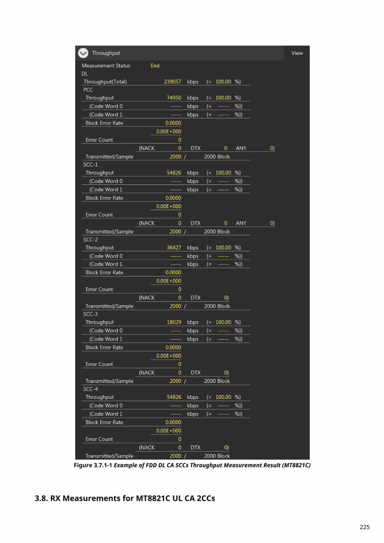
Figure 3.7.1-1 Example of FDD DL CA 5CCs Throughput Measurement Result (MT8821C)
RX Measurements for MT8821C UL CA 2CCs 3.8.
225
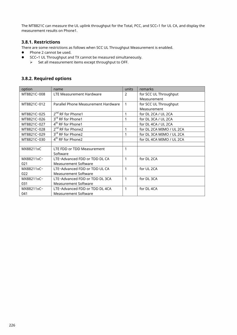
The MT8821C can measure the UL uplink throughput for the Total, PCC, and SCC–1 for UL CA, and display the measurement results on Phone1.
Restrictions 3.8.1.There are some restrictions as follows when SCC UL Throughput Measurement is enabled. Phone 2 cannot be used. SCC–1 UL Throughput and TX cannot be measured simultaneously.
Set all measurement items except throughput to OFF.
Required options 3.8.2. option name units remarks MT8821C–008 LTE Measurement Hardware 2 for SCC UL Throughput
Measurement MT8821C–012 Parallel Phone Measurement Hardware 1 for SCC UL Throughput
Measurement MT8821C–025 2nd RF for Phone1 1 for DL 2CA / UL 2CA MT8821C–026 3rd RF for Phone1 1 for DL 3CA / UL 2CA MT8821C–027 4th RF for Phone1 for DL 4CA / UL 2CA MT8821C–028 2nd RF for Phone2 1 for DL 2CA MIMO / UL 2CA MT8821C–029 3rd RF for Phone2 1 for DL 3CA MIMO / UL 2CA MT8821C–030 4th RF for Phone2 for DL 4CA MIMO / UL 2CA MX88211xC LTE FDD or TDD Measurement
Software 1
MX88211xC–
021 LTE–Advanced FDD or TDD DL CA Measurement Software
1 for DL 2CA
MX88211xC–
022 LTE–Advanced FDD or TDD UL CA Measurement Software
1 for UL 2CA
MX88211xC–
031 LTE–Advanced FDD or TDD DL 3CA Measurement Software
1 for DL 3CA
MX88211xC–
041 LTE–Advanced FDD or TDD DL 4CA Measurement Software
1 for DL 4CA
226
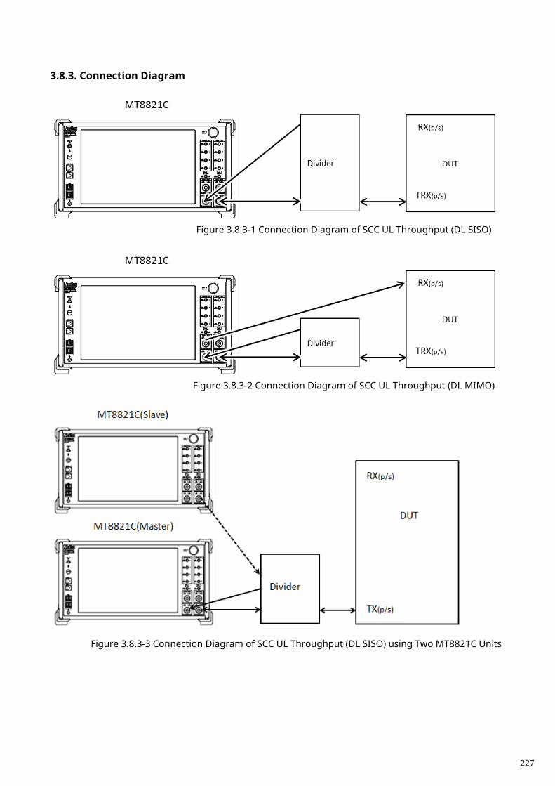
Connection Diagram 3.8.3.
Figure 3.8.3-1 Connection Diagram of SCC UL Throughput (DL SISO)
Figure 3.8.3-2 Connection Diagram of SCC UL Throughput (DL MIMO)
Figure 3.8.3-3 Connection Diagram of SCC UL Throughput (DL SISO) using Two MT8821C Units
227
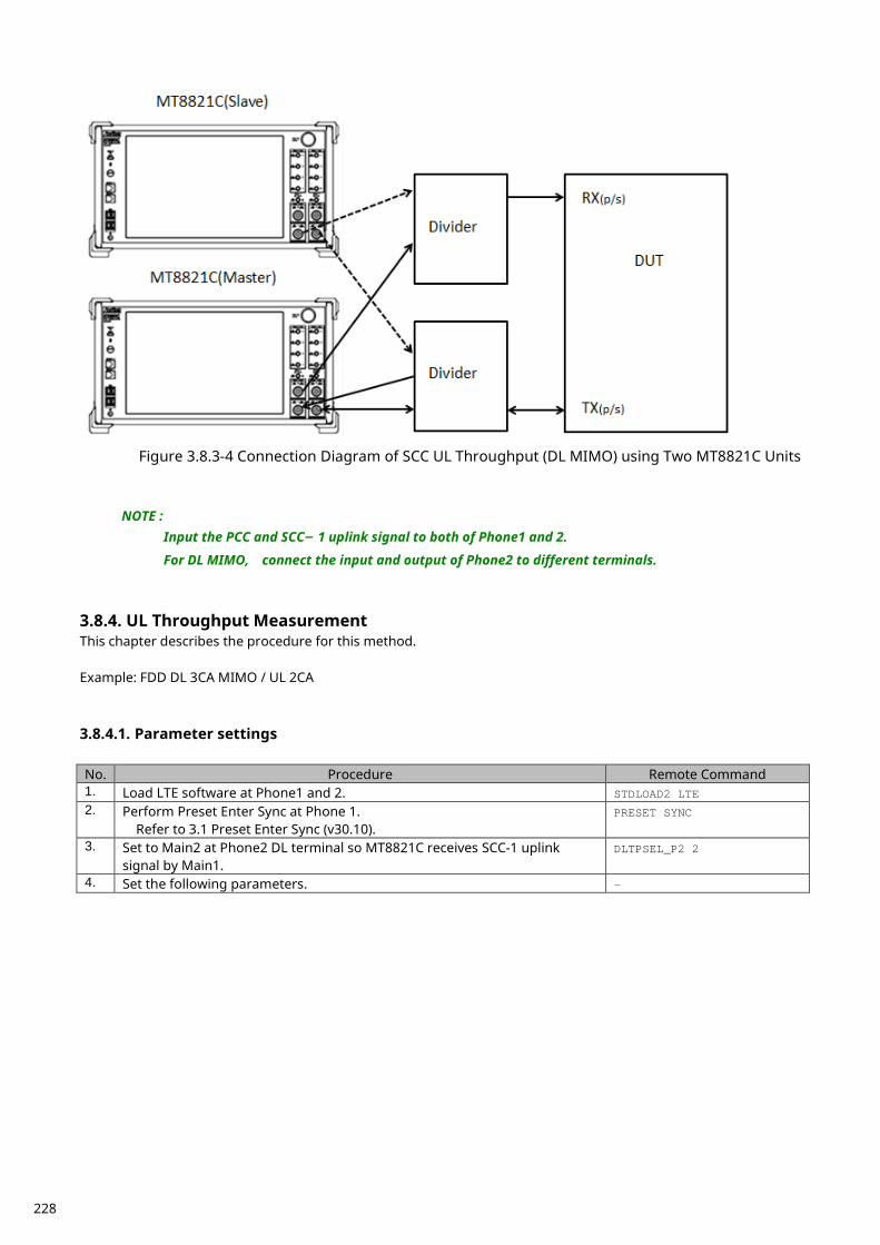
Figure 3.8.3-4 Connection Diagram of SCC UL Throughput (DL MIMO) using Two MT8821C Units
NOTE : Input the PCC and SCC– 1 uplink signal to both of Phone1 and 2.
For DL MIMO, connect the input and output of Phone2 to different terminals.
UL Throughput Measurement 3.8.4.This chapter describes the procedure for this method. Example: FDD DL 3CA MIMO / UL 2CA 3.8.4.1. Parameter settings No. Procedure Remote Command 1. Load LTE software at Phone1 and 2. STDLOAD2 LTE 2. Perform Preset Enter Sync at Phone 1.
Refer to 3.1 Preset Enter Sync (v30.10). PRESET SYNC
3. Set to Main2 at Phone2 DL terminal so MT8821C receives SCC-1 uplink signal by Main1.
DLTPSEL_P2 2
4. Set the following parameters. -
228
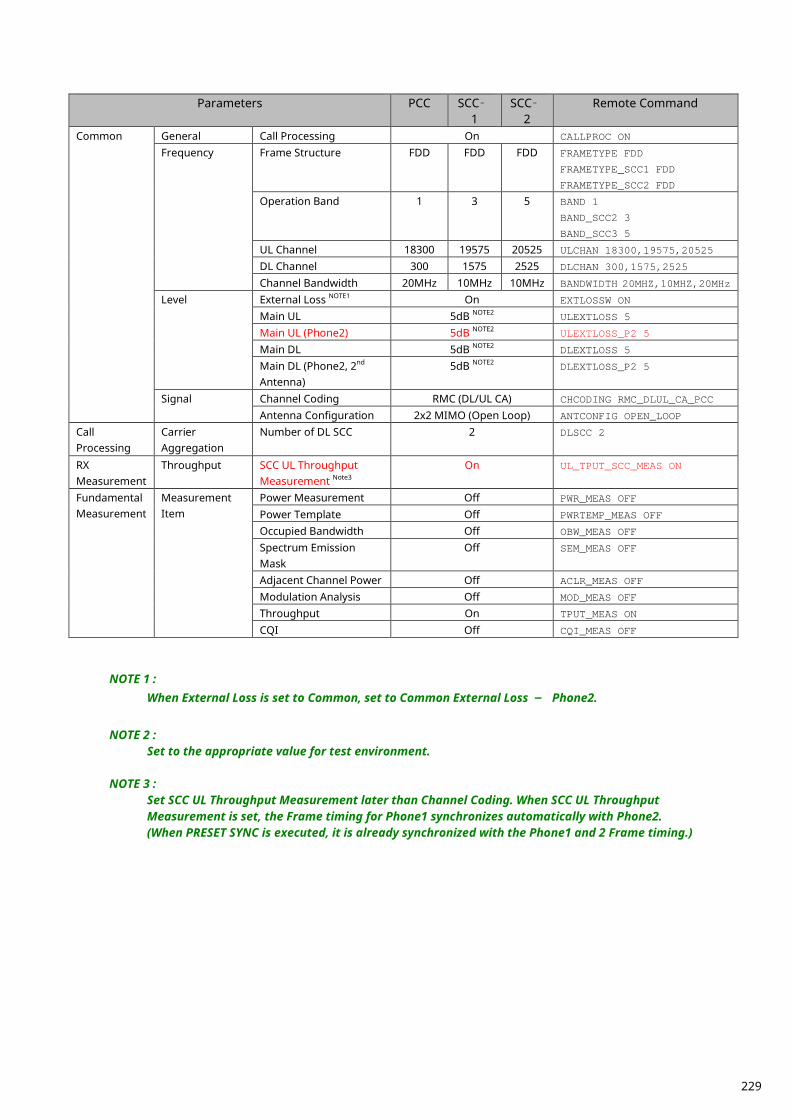
Parameters PCC SCC–
1 SCC–
2 Remote Command
Common General Call Processing On CALLPROC ON
Frequency Frame Structure FDD FDD FDD FRAMETYPE FDD
FRAMETYPE_SCC1 FDD
FRAMETYPE_SCC2 FDD
Operation Band 1 3 5 BAND 1
BAND_SCC2 3
BAND_SCC3 5
UL Channel 18300 19575 20525 ULCHAN 18300,19575,20525
DL Channel 300 1575 2525 DLCHAN 300,1575,2525
Channel Bandwidth 20MHz 10MHz 10MHz BANDWIDTH 20MHZ,10MHZ,20MHz
Level External Loss NOTE1 On EXTLOSSW ON
Main UL 5dB NOTE2 ULEXTLOSS 5
Main UL (Phone2) 5dB NOTE2 ULEXTLOSS_P2 5
Main DL 5dB NOTE2 DLEXTLOSS 5
Main DL (Phone2, 2nd Antenna)
5dB NOTE2 DLEXTLOSS_P2 5
Signal Channel Coding RMC (DL/UL CA) CHCODING RMC_DLUL_CA_PCC
Antenna Configuration 2x2 MIMO (Open Loop) ANTCONFIG OPEN_LOOP
Call Processing
Carrier Aggregation
Number of DL SCC 2 DLSCC 2
RX Measurement
Throughput SCC UL Throughput Measurement Note3
On UL_TPUT_SCC_MEAS ON
Fundamental Measurement
Measurement Item
Power Measurement Off PWR_MEAS OFF
Power Template Off PWRTEMP_MEAS OFF
Occupied Bandwidth Off OBW_MEAS OFF
Spectrum Emission Mask
Off SEM_MEAS OFF
Adjacent Channel Power Off ACLR_MEAS OFF
Modulation Analysis Off MOD_MEAS OFF
Throughput On TPUT_MEAS ON
CQI Off CQI_MEAS OFF
NOTE 1 : When External Loss is set to Common, set to Common External Loss – Phone2.
NOTE 2 :
Set to the appropriate value for test environment.
NOTE 3 : Set SCC UL Throughput Measurement later than Channel Coding. When SCC UL Throughput Measurement is set, the Frame timing for Phone1 synchronizes automatically with Phone2. (When PRESET SYNC is executed, it is already synchronized with the Phone1 and 2 Frame timing.)
229
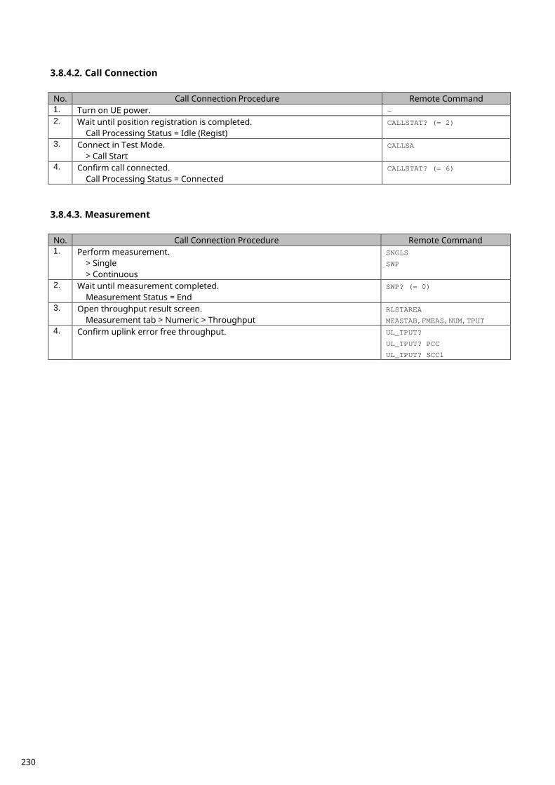
3.8.4.2. Call Connection No. Call Connection Procedure Remote Command 1. Turn on UE power. - 2. Wait until position registration is completed.
Call Processing Status = Idle (Regist) CALLSTAT? (= 2)
3. Connect in Test Mode. > Call Start
CALLSA
4. Confirm call connected. Call Processing Status = Connected
CALLSTAT? (= 6)
3.8.4.3. Measurement No. Call Connection Procedure Remote Command 1. Perform measurement.
> Single > Continuous
SNGLS
SWP
2. Wait until measurement completed. Measurement Status = End
SWP? (= 0)
3. Open throughput result screen. Measurement tab > Numeric > Throughput
RLSTAREA
MEASTAB,FMEAS,NUM,TPUT 4. Confirm uplink error free throughput. UL_TPUT?
UL_TPUT? PCC
UL_TPUT? SCC1
230
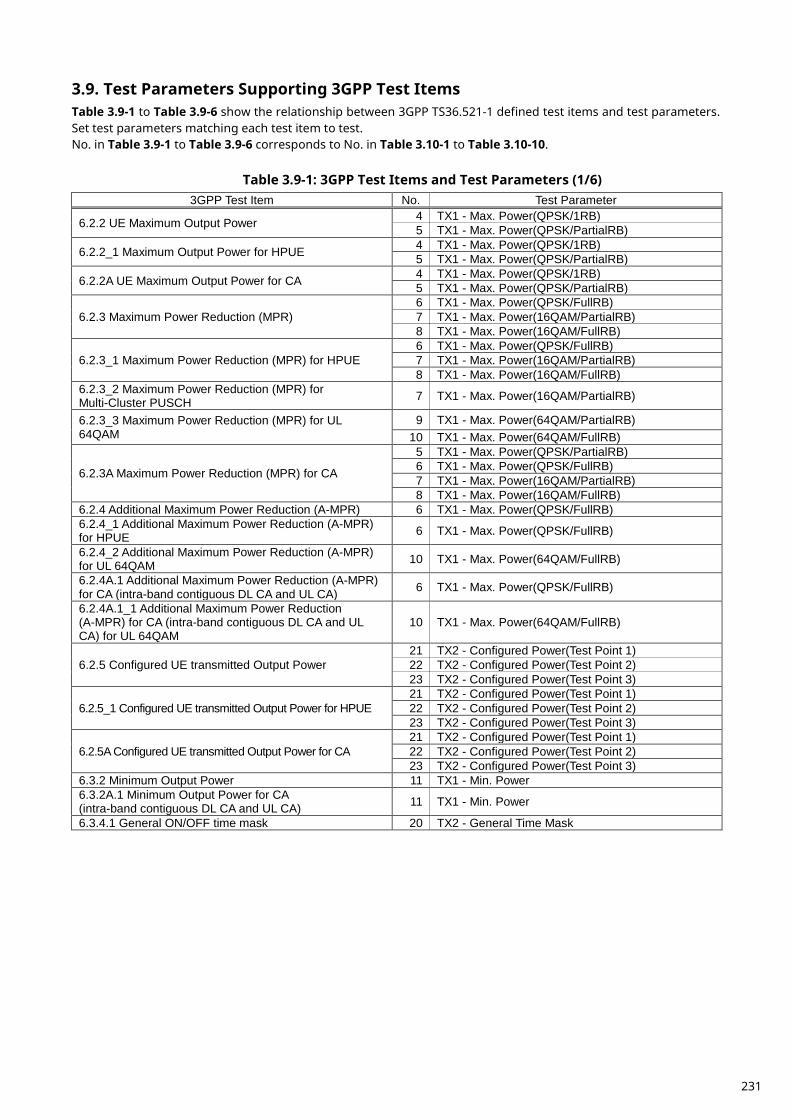
Test Parameters Supporting 3GPP Test Items 3.9.Table 3.9-1 to Table 3.9-6 show the relationship between 3GPP TS36.521-1 defined test items and test parameters. Set test parameters matching each test item to test. No. in Table 3.9-1 to Table 3.9-6 corresponds to No. in Table 3.10-1 to Table 3.10-10.
Table 3.9-1: 3GPP Test Items and Test Parameters (1/6) 3GPP Test Item No. Test Parameter
6.2.2 UE Maximum Output Power 4 TX1 - Max. Power(QPSK/1RB) 5 TX1 - Max. Power(QPSK/PartialRB)
6.2.2_1 Maximum Output Power for HPUE 4 TX1 - Max. Power(QPSK/1RB) 5 TX1 - Max. Power(QPSK/PartialRB)
6.2.2A UE Maximum Output Power for CA 4 TX1 - Max. Power(QPSK/1RB) 5 TX1 - Max. Power(QPSK/PartialRB)
6.2.3 Maximum Power Reduction (MPR) 6 TX1 - Max. Power(QPSK/FullRB) 7 TX1 - Max. Power(16QAM/PartialRB) 8 TX1 - Max. Power(16QAM/FullRB)
6.2.3_1 Maximum Power Reduction (MPR) for HPUE 6 TX1 - Max. Power(QPSK/FullRB) 7 TX1 - Max. Power(16QAM/PartialRB) 8 TX1 - Max. Power(16QAM/FullRB)
6.2.3_2 Maximum Power Reduction (MPR) for Multi-Cluster PUSCH 7 TX1 - Max. Power(16QAM/PartialRB)
6.2.3_3 Maximum Power Reduction (MPR) for UL 64QAM
9 TX1 - Max. Power(64QAM/PartialRB) 10 TX1 - Max. Power(64QAM/FullRB)
6.2.3A Maximum Power Reduction (MPR) for CA
5 TX1 - Max. Power(QPSK/PartialRB) 6 TX1 - Max. Power(QPSK/FullRB) 7 TX1 - Max. Power(16QAM/PartialRB) 8 TX1 - Max. Power(16QAM/FullRB)
6.2.4 Additional Maximum Power Reduction (A-MPR) 6 TX1 - Max. Power(QPSK/FullRB) 6.2.4_1 Additional Maximum Power Reduction (A-MPR) for HPUE 6 TX1 - Max. Power(QPSK/FullRB)
6.2.4_2 Additional Maximum Power Reduction (A-MPR) for UL 64QAM 10 TX1 - Max. Power(64QAM/FullRB)
6.2.4A.1 Additional Maximum Power Reduction (A-MPR) for CA (intra-band contiguous DL CA and UL CA) 6 TX1 - Max. Power(QPSK/FullRB)
6.2.4A.1_1 Additional Maximum Power Reduction (A-MPR) for CA (intra-band contiguous DL CA and UL CA) for UL 64QAM
10 TX1 - Max. Power(64QAM/FullRB)
6.2.5 Configured UE transmitted Output Power 21 TX2 - Configured Power(Test Point 1) 22 TX2 - Configured Power(Test Point 2) 23 TX2 - Configured Power(Test Point 3)
6.2.5_1 Configured UE transmitted Output Power for HPUE 21 TX2 - Configured Power(Test Point 1) 22 TX2 - Configured Power(Test Point 2) 23 TX2 - Configured Power(Test Point 3)
6.2.5A Configured UE transmitted Output Power for CA 21 TX2 - Configured Power(Test Point 1) 22 TX2 - Configured Power(Test Point 2) 23 TX2 - Configured Power(Test Point 3)
6.3.2 Minimum Output Power 11 TX1 - Min. Power 6.3.2A.1 Minimum Output Power for CA (intra-band contiguous DL CA and UL CA) 11 TX1 - Min. Power
6.3.4.1 General ON/OFF time mask 20 TX2 - General Time Mask
231
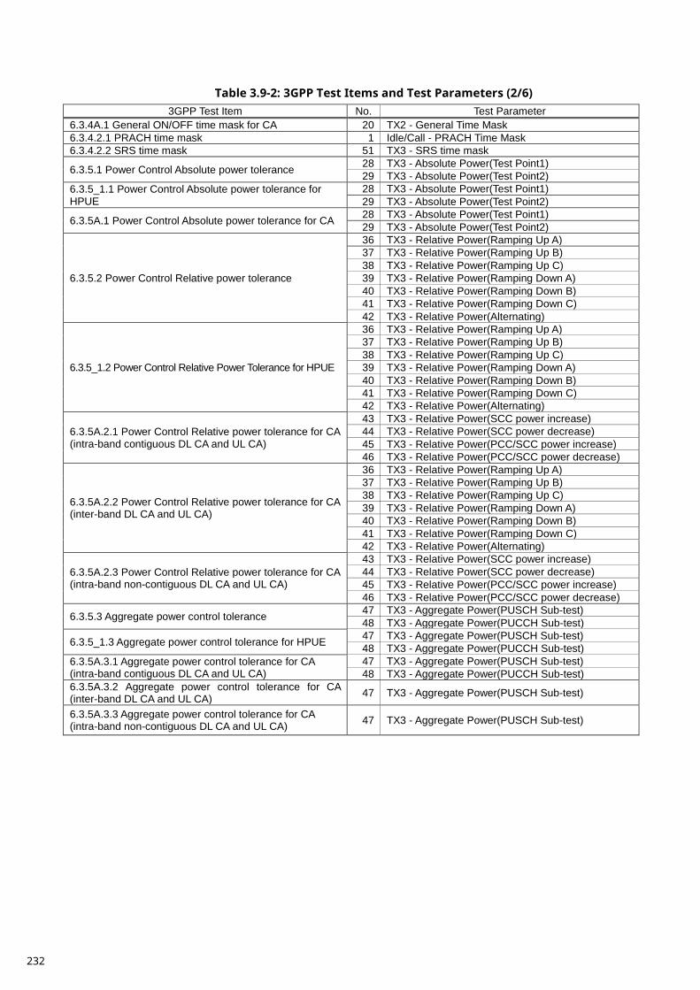
Table 3.9-2: 3GPP Test Items and Test Parameters (2/6)
3GPP Test Item No. Test Parameter 6.3.4A.1 General ON/OFF time mask for CA 20 TX2 - General Time Mask 6.3.4.2.1 PRACH time mask 1 Idle/Call - PRACH Time Mask 6.3.4.2.2 SRS time mask 51 TX3 - SRS time mask
6.3.5.1 Power Control Absolute power tolerance 28 TX3 - Absolute Power(Test Point1) 29 TX3 - Absolute Power(Test Point2)
6.3.5_1.1 Power Control Absolute power tolerance for HPUE
28 TX3 - Absolute Power(Test Point1) 29 TX3 - Absolute Power(Test Point2)
6.3.5A.1 Power Control Absolute power tolerance for CA 28 TX3 - Absolute Power(Test Point1) 29 TX3 - Absolute Power(Test Point2)
6.3.5.2 Power Control Relative power tolerance
36 TX3 - Relative Power(Ramping Up A) 37 TX3 - Relative Power(Ramping Up B) 38 TX3 - Relative Power(Ramping Up C) 39 TX3 - Relative Power(Ramping Down A) 40 TX3 - Relative Power(Ramping Down B) 41 TX3 - Relative Power(Ramping Down C) 42 TX3 - Relative Power(Alternating)
6.3.5_1.2 Power Control Relative Power Tolerance for HPUE
36 TX3 - Relative Power(Ramping Up A) 37 TX3 - Relative Power(Ramping Up B) 38 TX3 - Relative Power(Ramping Up C) 39 TX3 - Relative Power(Ramping Down A) 40 TX3 - Relative Power(Ramping Down B) 41 TX3 - Relative Power(Ramping Down C) 42 TX3 - Relative Power(Alternating)
6.3.5A.2.1 Power Control Relative power tolerance for CA (intra-band contiguous DL CA and UL CA)
43 TX3 - Relative Power(SCC power increase) 44 TX3 - Relative Power(SCC power decrease) 45 TX3 - Relative Power(PCC/SCC power increase) 46 TX3 - Relative Power(PCC/SCC power decrease)
6.3.5A.2.2 Power Control Relative power tolerance for CA (inter-band DL CA and UL CA)
36 TX3 - Relative Power(Ramping Up A) 37 TX3 - Relative Power(Ramping Up B) 38 TX3 - Relative Power(Ramping Up C) 39 TX3 - Relative Power(Ramping Down A) 40 TX3 - Relative Power(Ramping Down B) 41 TX3 - Relative Power(Ramping Down C) 42 TX3 - Relative Power(Alternating)
6.3.5A.2.3 Power Control Relative power tolerance for CA (intra-band non-contiguous DL CA and UL CA)
43 TX3 - Relative Power(SCC power increase) 44 TX3 - Relative Power(SCC power decrease) 45 TX3 - Relative Power(PCC/SCC power increase) 46 TX3 - Relative Power(PCC/SCC power decrease)
6.3.5.3 Aggregate power control tolerance 47 TX3 - Aggregate Power(PUSCH Sub-test) 48 TX3 - Aggregate Power(PUCCH Sub-test)
6.3.5_1.3 Aggregate power control tolerance for HPUE 47 TX3 - Aggregate Power(PUSCH Sub-test) 48 TX3 - Aggregate Power(PUCCH Sub-test)
6.3.5A.3.1 Aggregate power control tolerance for CA (intra-band contiguous DL CA and UL CA)
47 TX3 - Aggregate Power(PUSCH Sub-test) 48 TX3 - Aggregate Power(PUCCH Sub-test)
6.3.5A.3.2 Aggregate power control tolerance for CA (inter-band DL CA and UL CA) 47 TX3 - Aggregate Power(PUSCH Sub-test)
6.3.5A.3.3 Aggregate power control tolerance for CA (intra-band non-contiguous DL CA and UL CA) 47 TX3 - Aggregate Power(PUSCH Sub-test)
232
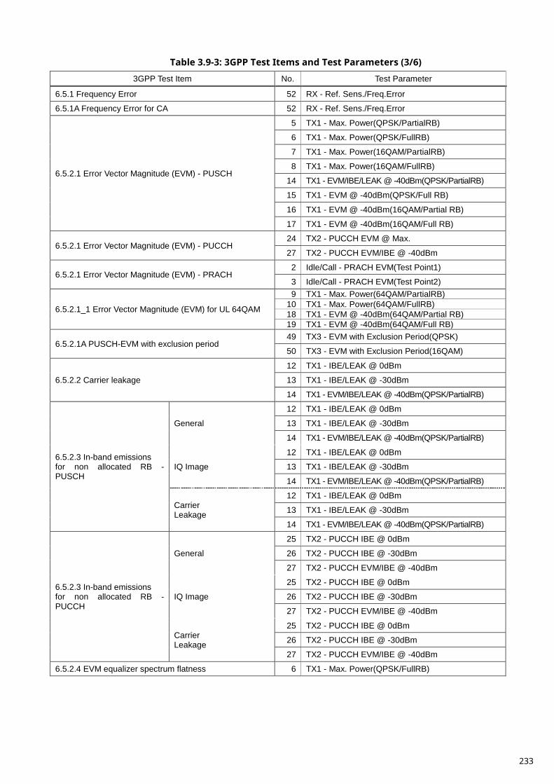
Table 3.9-3: 3GPP Test Items and Test Parameters (3/6)
3GPP Test Item No. Test Parameter
6.5.1 Frequency Error 52 RX - Ref. Sens./Freq.Error
6.5.1A Frequency Error for CA 52 RX - Ref. Sens./Freq.Error
6.5.2.1 Error Vector Magnitude (EVM) - PUSCH
5 TX1 - Max. Power(QPSK/PartialRB)
6 TX1 - Max. Power(QPSK/FullRB)
7 TX1 - Max. Power(16QAM/PartialRB)
8 TX1 - Max. Power(16QAM/FullRB)
14 TX1 - EVM/IBE/LEAK @ -40dBm(QPSK/PartialRB)
15 TX1 - EVM @ -40dBm(QPSK/Full RB)
16 TX1 - EVM @ -40dBm(16QAM/Partial RB)
17 TX1 - EVM @ -40dBm(16QAM/Full RB)
6.5.2.1 Error Vector Magnitude (EVM) - PUCCH 24 TX2 - PUCCH EVM @ Max.
27 TX2 - PUCCH EVM/IBE @ -40dBm
6.5.2.1 Error Vector Magnitude (EVM) - PRACH 2 Idle/Call - PRACH EVM(Test Point1)
3 Idle/Call - PRACH EVM(Test Point2)
6.5.2.1_1 Error Vector Magnitude (EVM) for UL 64QAM
9 TX1 - Max. Power(64QAM/PartialRB) 10 TX1 - Max. Power(64QAM/FullRB) 18 TX1 - EVM @ -40dBm(64QAM/Partial RB) 19 TX1 - EVM @ -40dBm(64QAM/Full RB)
6.5.2.1A PUSCH-EVM with exclusion period 49 TX3 - EVM with Exclusion Period(QPSK)
50 TX3 - EVM with Exclusion Period(16QAM)
6.5.2.2 Carrier leakage
12 TX1 - IBE/LEAK @ 0dBm
13 TX1 - IBE/LEAK @ -30dBm
14 TX1 - EVM/IBE/LEAK @ -40dBm(QPSK/PartialRB)
6.5.2.3 In-band emissions for non allocated RB - PUSCH
General
12 TX1 - IBE/LEAK @ 0dBm
13 TX1 - IBE/LEAK @ -30dBm
14 TX1 - EVM/IBE/LEAK @ -40dBm(QPSK/PartialRB)
IQ Image
12 TX1 - IBE/LEAK @ 0dBm
13 TX1 - IBE/LEAK @ -30dBm
14 TX1 - EVM/IBE/LEAK @ -40dBm(QPSK/PartialRB)
Carrier Leakage
12 TX1 - IBE/LEAK @ 0dBm
13 TX1 - IBE/LEAK @ -30dBm
14 TX1 - EVM/IBE/LEAK @ -40dBm(QPSK/PartialRB)
6.5.2.3 In-band emissions for non allocated RB - PUCCH
General
25 TX2 - PUCCH IBE @ 0dBm
26 TX2 - PUCCH IBE @ -30dBm
27 TX2 - PUCCH EVM/IBE @ -40dBm
IQ Image
25 TX2 - PUCCH IBE @ 0dBm
26 TX2 - PUCCH IBE @ -30dBm
27 TX2 - PUCCH EVM/IBE @ -40dBm
Carrier Leakage
25 TX2 - PUCCH IBE @ 0dBm
26 TX2 - PUCCH IBE @ -30dBm
27 TX2 - PUCCH EVM/IBE @ -40dBm
6.5.2.4 EVM equalizer spectrum flatness 6 TX1 - Max. Power(QPSK/FullRB)
233
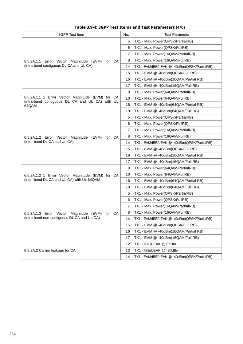
Table 3.9-4: 3GPP Test Items and Test Parameters (4/6)
3GPP Test Item No. Test Parameter
6.5.2A.1.1 Error Vector Magnitude (EVM) for CA (intra-band contiguous DL CA and UL CA)
5 TX1 - Max. Power(QPSK/PartialRB)
6 TX1 - Max. Power(QPSK/FullRB)
7 TX1 - Max. Power(16QAM/PartialRB)
8 TX1 - Max. Power(16QAM/FullRB)
14 TX1 - EVM/IBE/LEAK @ -40dBm(QPSK/PartialRB)
15 TX1 - EVM @ -40dBm(QPSK/Full RB)
16 TX1 - EVM @ -40dBm(16QAM/Partial RB)
17 TX1 - EVM @ -40dBm(16QAM/Full RB)
6.5.2A.1.1_1 Error Vector Magnitude (EVM) for CA (intra-band contiguous DL CA and UL CA) with UL 64QAM
9 TX1 - Max. Power(64QAM/PartialRB)
10 TX1 - Max. Power(64QAM/FullRB)
18 TX1 - EVM @ -40dBm(64QAM/Partial RB)
19 TX1 - EVM @ -40dBm(64QAM/Full RB)
6.5.2A.1.2 Error Vector Magnitude (EVM) for CA (inter-band DL CA and UL CA)
5 TX1 - Max. Power(QPSK/PartialRB)
6 TX1 - Max. Power(QPSK/FullRB)
7 TX1 - Max. Power(16QAM/PartialRB)
8 TX1 - Max. Power(16QAM/FullRB)
14 TX1 - EVM/IBE/LEAK @ -40dBm(QPSK/PartialRB)
15 TX1 - EVM @ -40dBm(QPSK/Full RB)
16 TX1 - EVM @ -40dBm(16QAM/Partial RB)
17 TX1 - EVM @ -40dBm(16QAM/Full RB)
6.5.2A.1.2_1 Error Vector Magnitude (EVM) for CA (inter-band DL CA and UL CA) with UL 64QAM
9 TX1 - Max. Power(64QAM/PartialRB)
10 TX1 - Max. Power(64QAM/FullRB)
18 TX1 - EVM @ -40dBm(64QAM/Partial RB)
19 TX1 - EVM @ -40dBm(64QAM/Full RB)
6.5.2A.1.3 Error Vector Magnitude (EVM) for CA (intra-band non-contiguous DL CA and UL CA)
5 TX1 - Max. Power(QPSK/PartialRB)
6 TX1 - Max. Power(QPSK/FullRB)
7 TX1 - Max. Power(16QAM/PartialRB)
8 TX1 - Max. Power(16QAM/FullRB)
14 TX1 - EVM/IBE/LEAK @ -40dBm(QPSK/PartialRB)
15 TX1 - EVM @ -40dBm(QPSK/Full RB)
16 TX1 - EVM @ -40dBm(16QAM/Partial RB)
17 TX1 - EVM @ -40dBm(16QAM/Full RB)
6.5.2A.2 Carrier leakage for CA
12 TX1 - IBE/LEAK @ 0dBm
13 TX1 - IBE/LEAK @ -30dBm
14 TX1 - EVM/IBE/LEAK @ -40dBm(QPSK/PartialRB)
234
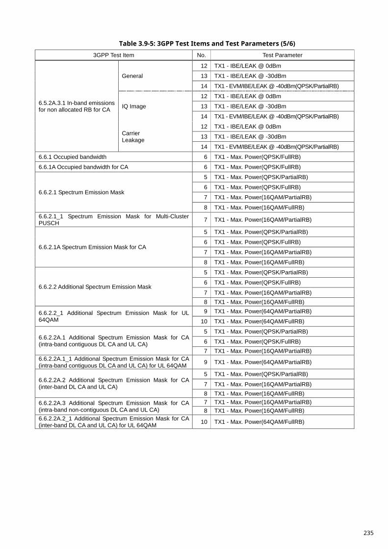
Table 3.9-5: 3GPP Test Items and Test Parameters (5/6)
3GPP Test Item No. Test Parameter
6.5.2A.3.1 In-band emissions for non allocated RB for CA
General
12 TX1 - IBE/LEAK @ 0dBm
13 TX1 - IBE/LEAK @ -30dBm
14 TX1 - EVM/IBE/LEAK @ -40dBm(QPSK/PartialRB)
IQ Image
12 TX1 - IBE/LEAK @ 0dBm
13 TX1 - IBE/LEAK @ -30dBm
14 TX1 - EVM/IBE/LEAK @ -40dBm(QPSK/PartialRB)
Carrier Leakage
12 TX1 - IBE/LEAK @ 0dBm
13 TX1 - IBE/LEAK @ -30dBm
14 TX1 - EVM/IBE/LEAK @ -40dBm(QPSK/PartialRB)
6.6.1 Occupied bandwidth 6 TX1 - Max. Power(QPSK/FullRB)
6.6.1A Occupied bandwidth for CA 6 TX1 - Max. Power(QPSK/FullRB)
6.6.2.1 Spectrum Emission Mask
5 TX1 - Max. Power(QPSK/PartialRB)
6 TX1 - Max. Power(QPSK/FullRB)
7 TX1 - Max. Power(16QAM/PartialRB)
8 TX1 - Max. Power(16QAM/FullRB) 6.6.2.1_1 Spectrum Emission Mask for Multi-Cluster PUSCH 7 TX1 - Max. Power(16QAM/PartialRB)
6.6.2.1A Spectrum Emission Mask for CA
5 TX1 - Max. Power(QPSK/PartialRB)
6 TX1 - Max. Power(QPSK/FullRB)
7 TX1 - Max. Power(16QAM/PartialRB)
8 TX1 - Max. Power(16QAM/FullRB)
6.6.2.2 Additional Spectrum Emission Mask
5 TX1 - Max. Power(QPSK/PartialRB)
6 TX1 - Max. Power(QPSK/FullRB)
7 TX1 - Max. Power(16QAM/PartialRB) 8 TX1 - Max. Power(16QAM/FullRB)
6.6.2.2_1 Additional Spectrum Emission Mask for UL 64QAM
9 TX1 - Max. Power(64QAM/PartialRB)
10 TX1 - Max. Power(64QAM/FullRB)
6.6.2.2A.1 Additional Spectrum Emission Mask for CA (intra-band contiguous DL CA and UL CA)
5 TX1 - Max. Power(QPSK/PartialRB)
6 TX1 - Max. Power(QPSK/FullRB) 7 TX1 - Max. Power(16QAM/PartialRB)
6.6.2.2A.1_1 Additional Spectrum Emission Mask for CA (intra-band contiguous DL CA and UL CA) for UL 64QAM 9 TX1 - Max. Power(64QAM/PartialRB)
6.6.2.2A.2 Additional Spectrum Emission Mask for CA (inter-band DL CA and UL CA)
5 TX1 - Max. Power(QPSK/PartialRB)
7 TX1 - Max. Power(16QAM/PartialRB) 8 TX1 - Max. Power(16QAM/FullRB)
6.6.2.2A.3 Additional Spectrum Emission Mask for CA (intra-band non-contiguous DL CA and UL CA)
7 TX1 - Max. Power(16QAM/PartialRB) 8 TX1 - Max. Power(16QAM/FullRB)
6.6.2.2A.2_1 Additional Spectrum Emission Mask for CA (inter-band DL CA and UL CA) for UL 64QAM 10 TX1 - Max. Power(64QAM/FullRB)
235
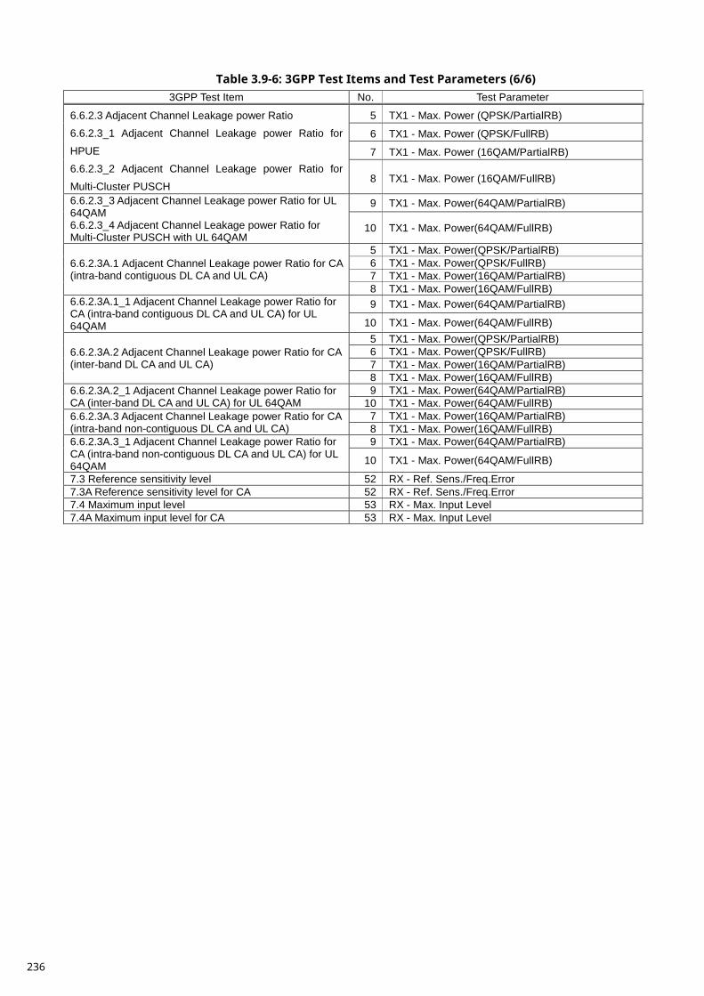
Table 3.9-6: 3GPP Test Items and Test Parameters (6/6) 3GPP Test Item No. Test Parameter
6.6.2.3 Adjacent Channel Leakage power Ratio
6.6.2.3_1 Adjacent Channel Leakage power Ratio for
HPUE
6.6.2.3_2 Adjacent Channel Leakage power Ratio for
Multi-Cluster PUSCH
5 TX1 - Max. Power (QPSK/PartialRB)
6 TX1 - Max. Power (QPSK/FullRB)
7 TX1 - Max. Power (16QAM/PartialRB)
8 TX1 - Max. Power (16QAM/FullRB)
6.6.2.3_3 Adjacent Channel Leakage power Ratio for UL 64QAM 6.6.2.3_4 Adjacent Channel Leakage power Ratio for Multi-Cluster PUSCH with UL 64QAM
9 TX1 - Max. Power(64QAM/PartialRB)
10 TX1 - Max. Power(64QAM/FullRB)
6.6.2.3A.1 Adjacent Channel Leakage power Ratio for CA (intra-band contiguous DL CA and UL CA)
5 TX1 - Max. Power(QPSK/PartialRB) 6 TX1 - Max. Power(QPSK/FullRB) 7 TX1 - Max. Power(16QAM/PartialRB) 8 TX1 - Max. Power(16QAM/FullRB)
6.6.2.3A.1_1 Adjacent Channel Leakage power Ratio for CA (intra-band contiguous DL CA and UL CA) for UL 64QAM
9 TX1 - Max. Power(64QAM/PartialRB)
10 TX1 - Max. Power(64QAM/FullRB)
6.6.2.3A.2 Adjacent Channel Leakage power Ratio for CA (inter-band DL CA and UL CA)
5 TX1 - Max. Power(QPSK/PartialRB) 6 TX1 - Max. Power(QPSK/FullRB) 7 TX1 - Max. Power(16QAM/PartialRB) 8 TX1 - Max. Power(16QAM/FullRB)
6.6.2.3A.2_1 Adjacent Channel Leakage power Ratio for CA (inter-band DL CA and UL CA) for UL 64QAM
9 TX1 - Max. Power(64QAM/PartialRB) 10 TX1 - Max. Power(64QAM/FullRB)
6.6.2.3A.3 Adjacent Channel Leakage power Ratio for CA (intra-band non-contiguous DL CA and UL CA)
7 TX1 - Max. Power(16QAM/PartialRB) 8 TX1 - Max. Power(16QAM/FullRB)
6.6.2.3A.3_1 Adjacent Channel Leakage power Ratio for CA (intra-band non-contiguous DL CA and UL CA) for UL 64QAM
9 TX1 - Max. Power(64QAM/PartialRB)
10 TX1 - Max. Power(64QAM/FullRB)
7.3 Reference sensitivity level 52 RX - Ref. Sens./Freq.Error 7.3A Reference sensitivity level for CA 52 RX - Ref. Sens./Freq.Error 7.4 Maximum input level 53 RX - Max. Input Level 7.4A Maximum input level for CA 53 RX - Max. Input Level
236
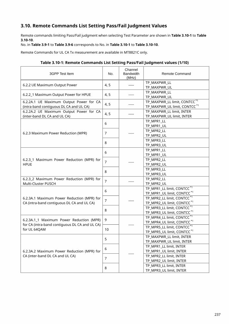
Remote Commands List Setting Pass/Fail Judgment Values 3.10. Remote commands limiting Pass/Fail judgment when selecting Test Parameter are shown in Table 3.10-1 to Table 3.10-10. No. in Table 3.9-1 to Table 3.9-6 corresponds to No. in Table 3.10-1 to Table 3.10-10. Remote Commands for UL CA Tx measurement are available in MT8821C only.
Table 3.10-1: Remote Commands List Setting Pass/Fail Judgment values (1/10)
3GPP Test Item No. Channel
Bandwidth (MHz)
Remote Command
6.2.2 UE Maximum Output Power 4, 5 ----- TP_MAXPWR_LL TP_MAXPWR_UL
6.2.2_1 Maximum Output Power for HPUE 4, 5 ----- TP_MAXPWR_LL TP_MAXPWR_UL
6.2.2A.1 UE Maximum Output Power for CA (intra-band contiguous DL CA and UL CA)
4, 5 ----- TP_MAXPWR_LL limit, CONTCC *1 TP_MAXPWR_UL limit, CONTCC *1
6.2.2A.2 UE Maximum Output Power for CA (inter-band DL CA and UL CA)
4, 5 ----- TP_MAXPWR_LL limit, INTER TP_MAXPWR_UL limit, INTER
6.2.3 Maximum Power Reduction (MPR)
6
-----
TP_MPR1_LL TP_MPR1_UL
7 TP_MPR2_LL TP_MPR2_UL
8 TP_MPR3_LL TP_MPR3_UL
6.2.3_1 Maximum Power Reduction (MPR) for HPUE
6
-----
TP_MPR1_LL TP_MPR1_UL
7 TP_MPR2_LL TP_MPR2_UL
8 TP_MPR3_LL TP_MPR3_UL
6.2.3_2 Maximum Power Reduction (MPR) for Multi-Cluster PUSCH
7 ----- TP_MPR2_LL TP_MPR2_UL
6.2.3A.1 Maximum Power Reduction (MPR) for CA (intra-band contiguous DL CA and UL CA)
6
-----
TP_MPR1_LL limit, CONTCC *1 TP_MPR1_UL limit, CONTCC *1
7 TP_MPR2_LL limit, CONTCC *1 TP_MPR2_UL limit, CONTCC *1
8 TP_MPR3_LL limit, CONTCC *1 TP_MPR3_UL limit, CONTCC *1
6.2.3A.1_1 Maximum Power Reduction (MPR) for CA (intra-band contiguous DL CA and UL CA) for UL 64QAM
9 -----
TP_MPR4_LL limit, CONTCC *1 TP_MPR4_UL limit, CONTCC *1
10 TP_MPR5_LL limit, CONTCC *1 TP_MPR5_UL limit, CONTCC *1
6.2.3A.2 Maximum Power Reduction (MPR) for CA (inter-band DL CA and UL CA)
5
-----
TP_MAXPWR_LL limit, INTER TP_MAXPWR_UL limit, INTER
6 TP_MPR1_LL limit, INTER TP_MPR1_UL limit, INTER
7 TP_MPR2_LL limit, INTER TP_MPR2_UL limit, INTER
8 TP_MPR3_LL limit, INTER TP_MPR3_UL limit, INTER
237
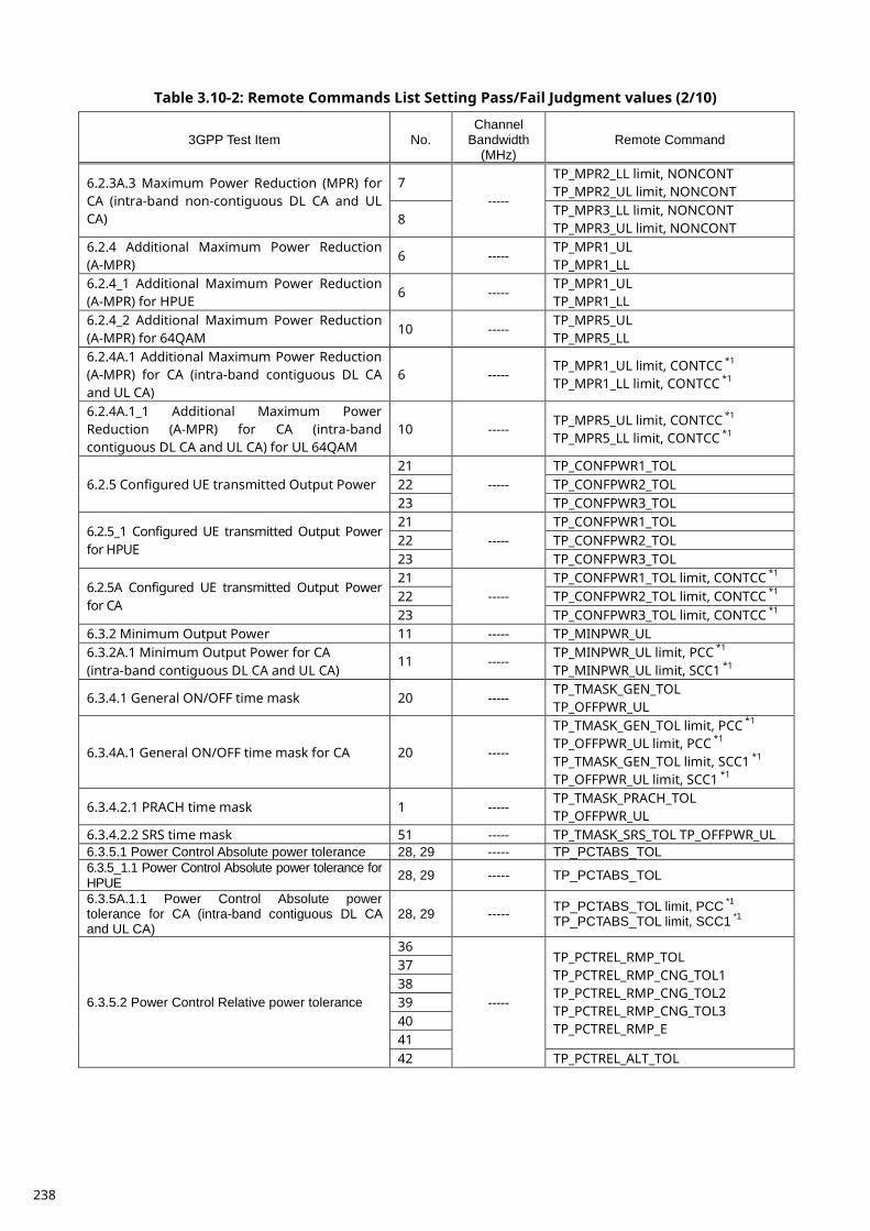
Table 3.10-2: Remote Commands List Setting Pass/Fail Judgment values (2/10)
3GPP Test Item No. Channel
Bandwidth (MHz)
Remote Command
6.2.3A.3 Maximum Power Reduction (MPR) for CA (intra-band non-contiguous DL CA and UL CA)
7 -----
TP_MPR2_LL limit, NONCONT TP_MPR2_UL limit, NONCONT
8 TP_MPR3_LL limit, NONCONT TP_MPR3_UL limit, NONCONT
6.2.4 Additional Maximum Power Reduction (A-MPR)
6 ----- TP_MPR1_UL TP_MPR1_LL
6.2.4_1 Additional Maximum Power Reduction (A-MPR) for HPUE
6 ----- TP_MPR1_UL TP_MPR1_LL
6.2.4_2 Additional Maximum Power Reduction (A-MPR) for 64QAM
10 ----- TP_MPR5_UL TP_MPR5_LL
6.2.4A.1 Additional Maximum Power Reduction (A-MPR) for CA (intra-band contiguous DL CA and UL CA)
6 ----- TP_MPR1_UL limit, CONTCC *1 TP_MPR1_LL limit, CONTCC *1
6.2.4A.1_1 Additional Maximum Power Reduction (A-MPR) for CA (intra-band contiguous DL CA and UL CA) for UL 64QAM
10 ----- TP_MPR5_UL limit, CONTCC *1 TP_MPR5_LL limit, CONTCC *1
6.2.5 Configured UE transmitted Output Power 21
----- TP_CONFPWR1_TOL
22 TP_CONFPWR2_TOL 23 TP_CONFPWR3_TOL
6.2.5_1 Configured UE transmitted Output Power for HPUE
21 -----
TP_CONFPWR1_TOL 22 TP_CONFPWR2_TOL 23 TP_CONFPWR3_TOL
6.2.5A Configured UE transmitted Output Power for CA
21 -----
TP_CONFPWR1_TOL limit, CONTCC *1 22 TP_CONFPWR2_TOL limit, CONTCC *1 23 TP_CONFPWR3_TOL limit, CONTCC *1
6.3.2 Minimum Output Power 11 ----- TP_MINPWR_UL 6.3.2A.1 Minimum Output Power for CA (intra-band contiguous DL CA and UL CA)
11 ----- TP_MINPWR_UL limit, PCC *1 TP_MINPWR_UL limit, SCC1 *1
6.3.4.1 General ON/OFF time mask 20 ----- TP_TMASK_GEN_TOL TP_OFFPWR_UL
6.3.4A.1 General ON/OFF time mask for CA 20 -----
TP_TMASK_GEN_TOL limit, PCC *1 TP_OFFPWR_UL limit, PCC *1 TP_TMASK_GEN_TOL limit, SCC1 *1 TP_OFFPWR_UL limit, SCC1 *1
6.3.4.2.1 PRACH time mask 1 ----- TP_TMASK_PRACH_TOL TP_OFFPWR_UL
6.3.4.2.2 SRS time mask 51 ----- TP_TMASK_SRS_TOL TP_OFFPWR_UL 6.3.5.1 Power Control Absolute power tolerance 28, 29 ----- TP_PCTABS_TOL 6.3.5_1.1 Power Control Absolute power tolerance for HPUE 28, 29 ----- TP_PCTABS_TOL
6.3.5A.1.1 Power Control Absolute power tolerance for CA (intra-band contiguous DL CA and UL CA)
28, 29 ----- TP_PCTABS_TOL limit, PCC *1 TP_PCTABS_TOL limit, SCC1 *1
6.3.5.2 Power Control Relative power tolerance
36
-----
TP_PCTREL_RMP_TOL TP_PCTREL_RMP_CNG_TOL1 TP_PCTREL_RMP_CNG_TOL2 TP_PCTREL_RMP_CNG_TOL3 TP_PCTREL_RMP_E
37 38 39 40 41 42 TP_PCTREL_ALT_TOL
238
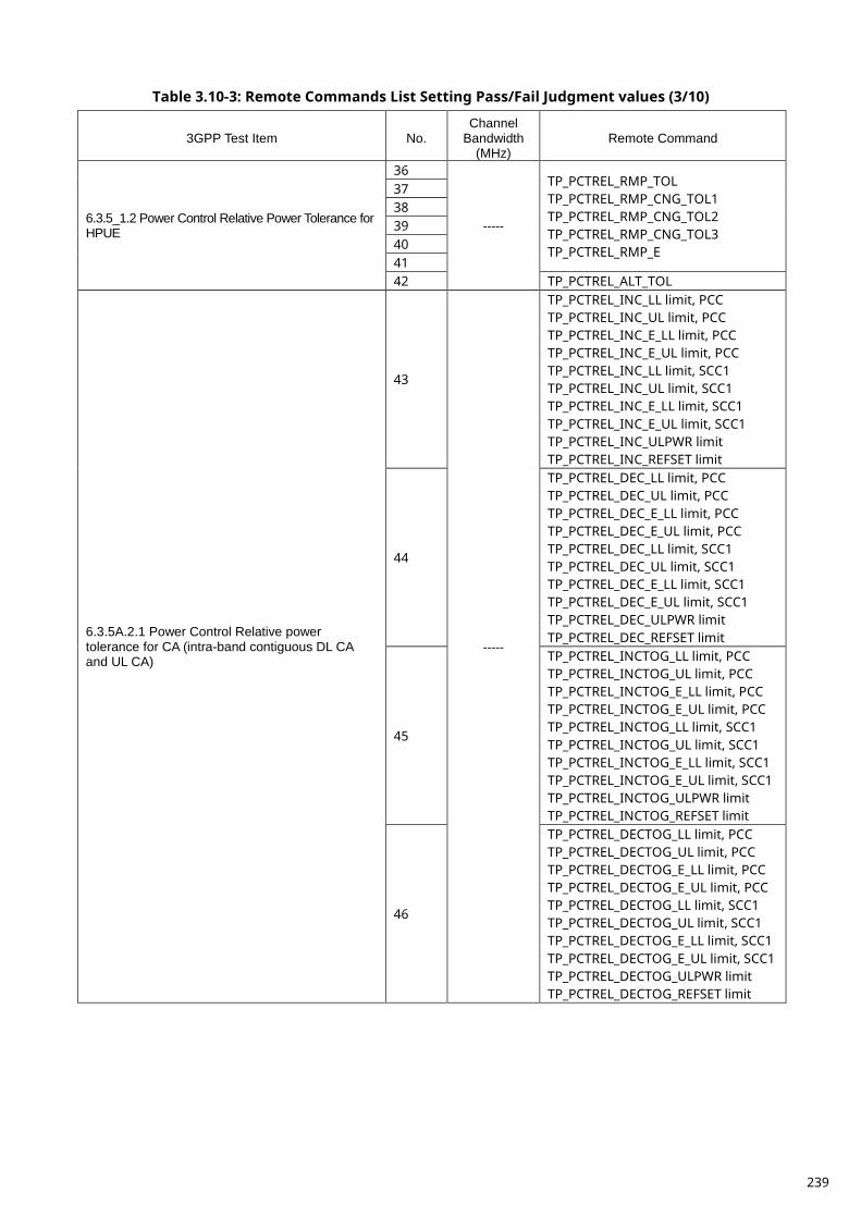
Table 3.10-3: Remote Commands List Setting Pass/Fail Judgment values (3/10)
3GPP Test Item No. Channel
Bandwidth (MHz)
Remote Command
6.3.5_1.2 Power Control Relative Power Tolerance for HPUE
36
-----
TP_PCTREL_RMP_TOL TP_PCTREL_RMP_CNG_TOL1 TP_PCTREL_RMP_CNG_TOL2 TP_PCTREL_RMP_CNG_TOL3 TP_PCTREL_RMP_E
37 38 39 40 41 42 TP_PCTREL_ALT_TOL
6.3.5A.2.1 Power Control Relative power tolerance for CA (intra-band contiguous DL CA and UL CA)
43
-----
TP_PCTREL_INC_LL limit, PCC TP_PCTREL_INC_UL limit, PCC TP_PCTREL_INC_E_LL limit, PCC TP_PCTREL_INC_E_UL limit, PCC TP_PCTREL_INC_LL limit, SCC1 TP_PCTREL_INC_UL limit, SCC1 TP_PCTREL_INC_E_LL limit, SCC1 TP_PCTREL_INC_E_UL limit, SCC1 TP_PCTREL_INC_ULPWR limit TP_PCTREL_INC_REFSET limit
44
TP_PCTREL_DEC_LL limit, PCC TP_PCTREL_DEC_UL limit, PCC TP_PCTREL_DEC_E_LL limit, PCC TP_PCTREL_DEC_E_UL limit, PCC TP_PCTREL_DEC_LL limit, SCC1 TP_PCTREL_DEC_UL limit, SCC1 TP_PCTREL_DEC_E_LL limit, SCC1 TP_PCTREL_DEC_E_UL limit, SCC1 TP_PCTREL_DEC_ULPWR limit TP_PCTREL_DEC_REFSET limit
45
TP_PCTREL_INCTOG_LL limit, PCC TP_PCTREL_INCTOG_UL limit, PCC TP_PCTREL_INCTOG_E_LL limit, PCC TP_PCTREL_INCTOG_E_UL limit, PCC TP_PCTREL_INCTOG_LL limit, SCC1 TP_PCTREL_INCTOG_UL limit, SCC1 TP_PCTREL_INCTOG_E_LL limit, SCC1 TP_PCTREL_INCTOG_E_UL limit, SCC1 TP_PCTREL_INCTOG_ULPWR limit TP_PCTREL_INCTOG_REFSET limit
46
TP_PCTREL_DECTOG_LL limit, PCC TP_PCTREL_DECTOG_UL limit, PCC TP_PCTREL_DECTOG_E_LL limit, PCC TP_PCTREL_DECTOG_E_UL limit, PCC TP_PCTREL_DECTOG_LL limit, SCC1 TP_PCTREL_DECTOG_UL limit, SCC1 TP_PCTREL_DECTOG_E_LL limit, SCC1 TP_PCTREL_DECTOG_E_UL limit, SCC1 TP_PCTREL_DECTOG_ULPWR limit TP_PCTREL_DECTOG_REFSET limit
239
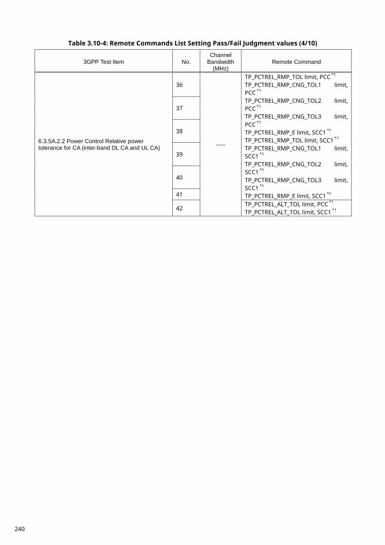
Table 3.10-4: Remote Commands List Setting Pass/Fail Judgment values (4/10)
3GPP Test Item No. Channel
Bandwidth (MHz)
Remote Command
6.3.5A.2.2 Power Control Relative power tolerance for CA (inter-band DL CA and UL CA)
36
-----
TP_PCTREL_RMP_TOL limit, PCC *1 TP_PCTREL_RMP_CNG_TOL1 limit, PCC *1 TP_PCTREL_RMP_CNG_TOL2 limit, PCC *1 TP_PCTREL_RMP_CNG_TOL3 limit, PCC *1 TP_PCTREL_RMP_E limit, SCC1 *1 TP_PCTREL_RMP_TOL limit, SCC1 *1 TP_PCTREL_RMP_CNG_TOL1 limit, SCC1 *1 TP_PCTREL_RMP_CNG_TOL2 limit, SCC1 *1 TP_PCTREL_RMP_CNG_TOL3 limit, SCC1 *1 TP_PCTREL_RMP_E limit, SCC1 *1
37
38
39
40
41
42 TP_PCTREL_ALT_TOL limit, PCC *1 TP_PCTREL_ALT_TOL limit, SCC1 *1
240
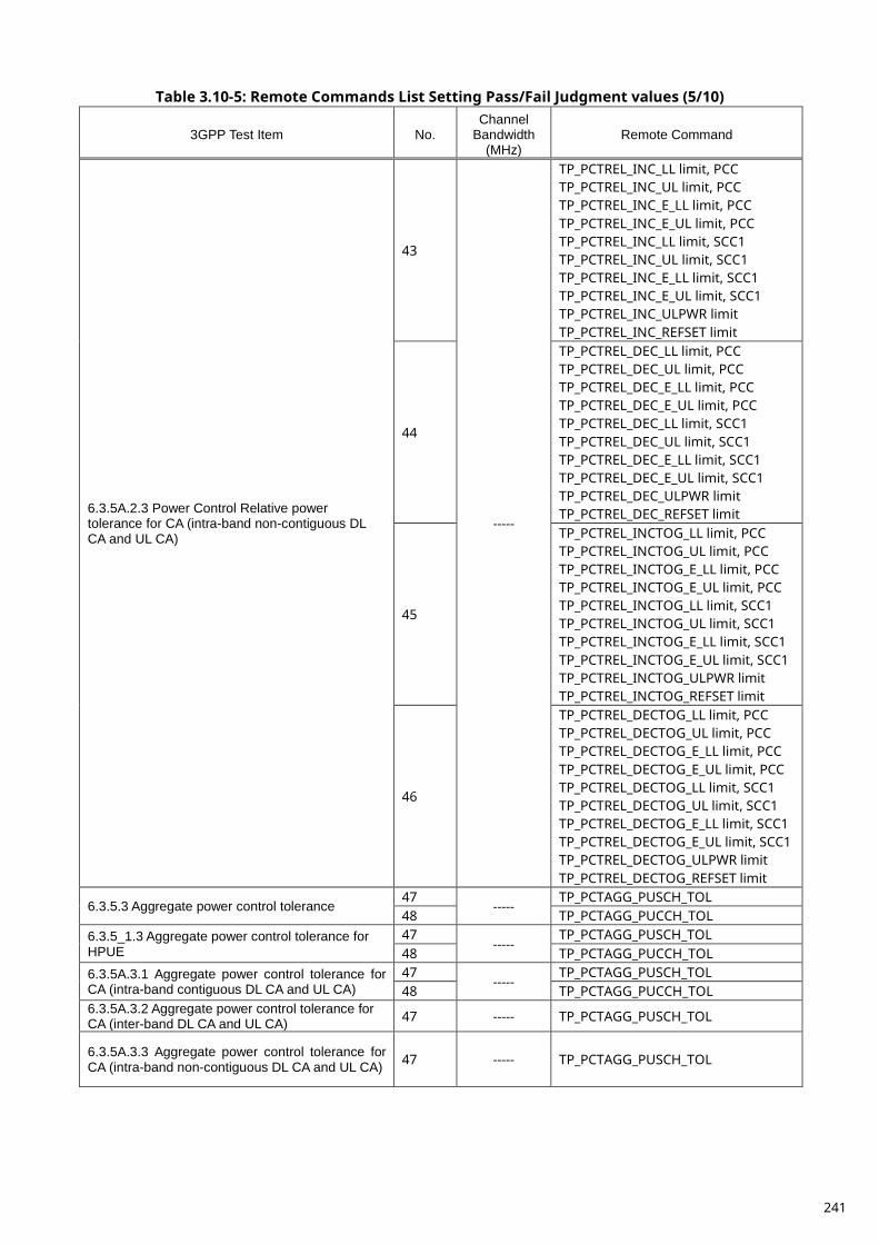
Table 3.10-5: Remote Commands List Setting Pass/Fail Judgment values (5/10)
3GPP Test Item No. Channel
Bandwidth (MHz)
Remote Command
6.3.5A.2.3 Power Control Relative power tolerance for CA (intra-band non-contiguous DL CA and UL CA)
43
-----
TP_PCTREL_INC_LL limit, PCC TP_PCTREL_INC_UL limit, PCC TP_PCTREL_INC_E_LL limit, PCC TP_PCTREL_INC_E_UL limit, PCC TP_PCTREL_INC_LL limit, SCC1 TP_PCTREL_INC_UL limit, SCC1 TP_PCTREL_INC_E_LL limit, SCC1 TP_PCTREL_INC_E_UL limit, SCC1 TP_PCTREL_INC_ULPWR limit TP_PCTREL_INC_REFSET limit
44
TP_PCTREL_DEC_LL limit, PCC TP_PCTREL_DEC_UL limit, PCC TP_PCTREL_DEC_E_LL limit, PCC TP_PCTREL_DEC_E_UL limit, PCC TP_PCTREL_DEC_LL limit, SCC1 TP_PCTREL_DEC_UL limit, SCC1 TP_PCTREL_DEC_E_LL limit, SCC1 TP_PCTREL_DEC_E_UL limit, SCC1 TP_PCTREL_DEC_ULPWR limit TP_PCTREL_DEC_REFSET limit
45
TP_PCTREL_INCTOG_LL limit, PCC TP_PCTREL_INCTOG_UL limit, PCC TP_PCTREL_INCTOG_E_LL limit, PCC TP_PCTREL_INCTOG_E_UL limit, PCC TP_PCTREL_INCTOG_LL limit, SCC1 TP_PCTREL_INCTOG_UL limit, SCC1 TP_PCTREL_INCTOG_E_LL limit, SCC1 TP_PCTREL_INCTOG_E_UL limit, SCC1 TP_PCTREL_INCTOG_ULPWR limit TP_PCTREL_INCTOG_REFSET limit
46
TP_PCTREL_DECTOG_LL limit, PCC TP_PCTREL_DECTOG_UL limit, PCC TP_PCTREL_DECTOG_E_LL limit, PCC TP_PCTREL_DECTOG_E_UL limit, PCC TP_PCTREL_DECTOG_LL limit, SCC1 TP_PCTREL_DECTOG_UL limit, SCC1 TP_PCTREL_DECTOG_E_LL limit, SCC1 TP_PCTREL_DECTOG_E_UL limit, SCC1 TP_PCTREL_DECTOG_ULPWR limit TP_PCTREL_DECTOG_REFSET limit
6.3.5.3 Aggregate power control tolerance 47
----- TP_PCTAGG_PUSCH_TOL
48 TP_PCTAGG_PUCCH_TOL 6.3.5_1.3 Aggregate power control tolerance for HPUE
47 -----
TP_PCTAGG_PUSCH_TOL 48 TP_PCTAGG_PUCCH_TOL
6.3.5A.3.1 Aggregate power control tolerance for CA (intra-band contiguous DL CA and UL CA)
47 -----
TP_PCTAGG_PUSCH_TOL 48 TP_PCTAGG_PUCCH_TOL
6.3.5A.3.2 Aggregate power control tolerance for CA (inter-band DL CA and UL CA) 47 ----- TP_PCTAGG_PUSCH_TOL
6.3.5A.3.3 Aggregate power control tolerance for CA (intra-band non-contiguous DL CA and UL CA) 47 ----- TP_PCTAGG_PUSCH_TOL
241
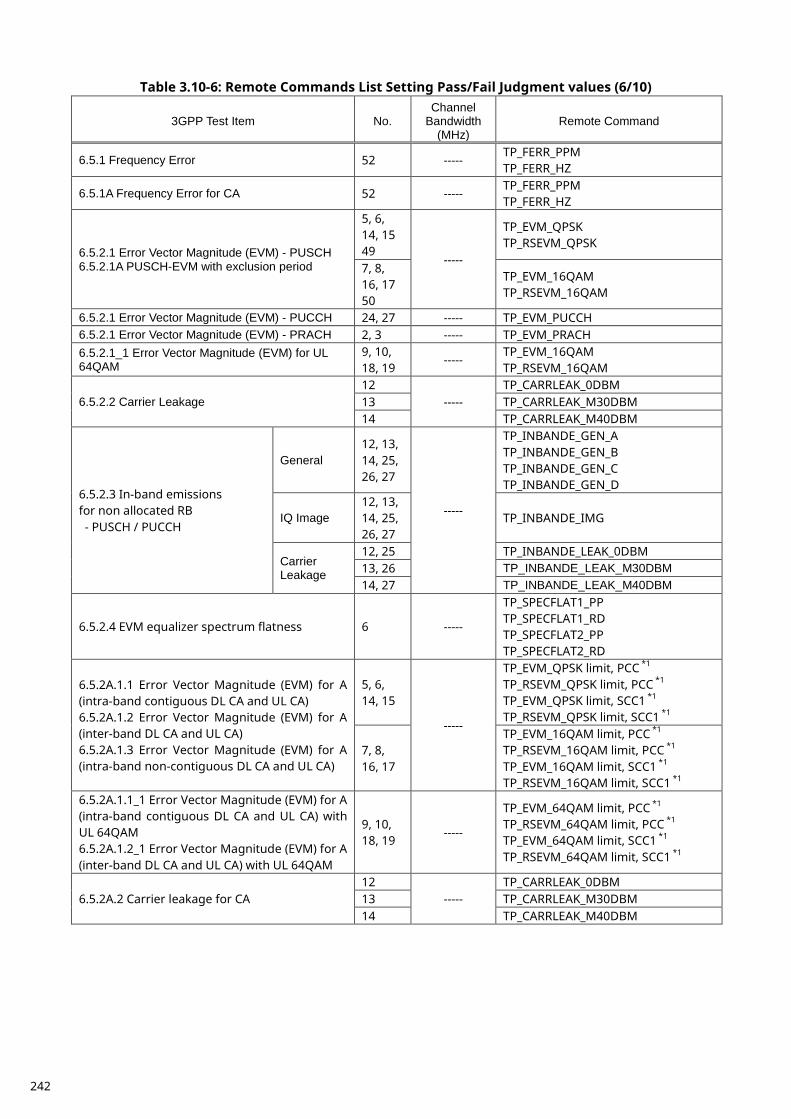
Table 3.10-6: Remote Commands List Setting Pass/Fail Judgment values (6/10)
3GPP Test Item No. Channel
Bandwidth (MHz)
Remote Command
6.5.1 Frequency Error 52 ----- TP_FERR_PPM TP_FERR_HZ
6.5.1A Frequency Error for CA 52 ----- TP_FERR_PPM TP_FERR_HZ
6.5.2.1 Error Vector Magnitude (EVM) - PUSCH 6.5.2.1A PUSCH-EVM with exclusion period
5, 6, 14, 15 49
-----
TP_EVM_QPSK TP_RSEVM_QPSK
7, 8, 16, 17 50
TP_EVM_16QAM TP_RSEVM_16QAM
6.5.2.1 Error Vector Magnitude (EVM) - PUCCH 24, 27 ----- TP_EVM_PUCCH 6.5.2.1 Error Vector Magnitude (EVM) - PRACH 2, 3 ----- TP_EVM_PRACH 6.5.2.1_1 Error Vector Magnitude (EVM) for UL 64QAM
9, 10, 18, 19
----- TP_EVM_16QAM TP_RSEVM_16QAM
6.5.2.2 Carrier Leakage 12
----- TP_CARRLEAK_0DBM
13 TP_CARRLEAK_M30DBM 14 TP_CARRLEAK_M40DBM
6.5.2.3 In-band emissions for non allocated RB - PUSCH / PUCCH
General 12, 13, 14, 25, 26, 27
-----
TP_INBANDE_GEN_A TP_INBANDE_GEN_B TP_INBANDE_GEN_C TP_INBANDE_GEN_D
IQ Image 12, 13, 14, 25, 26, 27
TP_INBANDE_IMG
Carrier Leakage
12, 25 TP_INBANDE_LEAK_0DBM 13, 26 TP_INBANDE_LEAK_M30DBM 14, 27 TP_INBANDE_LEAK_M40DBM
6.5.2.4 EVM equalizer spectrum flatness 6 -----
TP_SPECFLAT1_PP TP_SPECFLAT1_RD TP_SPECFLAT2_PP TP_SPECFLAT2_RD
6.5.2A.1.1 Error Vector Magnitude (EVM) for A (intra-band contiguous DL CA and UL CA) 6.5.2A.1.2 Error Vector Magnitude (EVM) for A (inter-band DL CA and UL CA) 6.5.2A.1.3 Error Vector Magnitude (EVM) for A (intra-band non-contiguous DL CA and UL CA)
5, 6, 14, 15
-----
TP_EVM_QPSK limit, PCC *1 TP_RSEVM_QPSK limit, PCC *1 TP_EVM_QPSK limit, SCC1 *1 TP_RSEVM_QPSK limit, SCC1 *1
7, 8, 16, 17
TP_EVM_16QAM limit, PCC *1 TP_RSEVM_16QAM limit, PCC *1 TP_EVM_16QAM limit, SCC1 *1 TP_RSEVM_16QAM limit, SCC1 *1
6.5.2A.1.1_1 Error Vector Magnitude (EVM) for A (intra-band contiguous DL CA and UL CA) with UL 64QAM 6.5.2A.1.2_1 Error Vector Magnitude (EVM) for A (inter-band DL CA and UL CA) with UL 64QAM
9, 10, 18, 19
-----
TP_EVM_64QAM limit, PCC *1 TP_RSEVM_64QAM limit, PCC *1 TP_EVM_64QAM limit, SCC1 *1 TP_RSEVM_64QAM limit, SCC1 *1
6.5.2A.2 Carrier leakage for CA 12
----- TP_CARRLEAK_0DBM
13 TP_CARRLEAK_M30DBM 14 TP_CARRLEAK_M40DBM
242
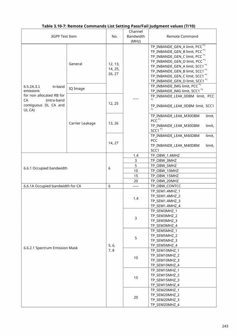
Table 3.10-7: Remote Commands List Setting Pass/Fail Judgment values (7/10)
3GPP Test Item No. Channel
Bandwidth (MHz)
Remote Command
6.5.2A.3.1 In-band emissions for non allocated RB for CA (intra-band contiguous DL CA and UL CA)
General 12, 13, 14, 25, 26, 27
-----
TP_INBANDE_GEN_A limit, PCC *1 TP_INBANDE_GEN_B limit, PCC *1 TP_INBANDE_GEN_C limit, PCC *1 TP_INBANDE_GEN_D limit, PCC *1 TP_INBANDE_GEN_A limit, SCC1 *1 TP_INBANDE_GEN_B limit, SCC1 *1 TP_INBANDE_GEN_C limit, SCC1 *1 TP_INBANDE_GEN_D limit, SCC1 *1
IQ Image TP_INBANDE_IMG limit, PCC *1 TP_INBANDE_IMG limit, SCC1 *1
Carrier Leakage
12, 25
TP_INBANDE_LEAK_0DBM limit, PCC
*1 TP_INBANDE_LEAK_0DBM limit, SCC1
*1
13, 26
TP_INBANDE_LEAK_M30DBM limit, PCC *1 TP_INBANDE_LEAK_M30DBM limit, SCC1 *1
14, 27
TP_INBANDE_LEAK_M40DBM limit, PCC TP_INBANDE_LEAK_M40DBM limit, SCC1
6.6.1 Occupied bandwidth 6
1.4 TP_OBW_1.4MHZ 3 TP_OBW_3MHZ 5 TP_OBW_5MHZ
10 TP_OBW_10MHZ 15 TP_OBW_15MHZ 20 TP_OBW_20MHZ
6.6.1A Occupied bandwidth for CA 6 ----- TP_OBW_CONTCC
6.6.2.1 Spectrum Emission Mask 5, 6, 7, 8
1.4
TP_SEM1.4MHZ_1 TP_SEM1.4MHZ_2 TP_SEM1.4MHZ_3 TP_SEM1.4MHZ_4
3
TP_SEM3MHZ_1 TP_SEM3MHZ_2 TP_SEM3MHZ_3 TP_SEM3MHZ_4
5
TP_SEM5MHZ_1 TP_SEM5MHZ_2 TP_SEM5MHZ_3 TP_SEM5MHZ_4
10
TP_SEM10MHZ_1 TP_SEM10MHZ_2 TP_SEM10MHZ_3 TP_SEM10MHZ_4
15
TP_SEM15MHZ_1 TP_SEM15MHZ_2 TP_SEM15MHZ_3 TP_SEM15MHZ_4
20
TP_SEM20MHZ_1 TP_SEM20MHZ_2 TP_SEM20MHZ_3 TP_SEM20MHZ_4
243

Table 3.10-8: Remote Commands List Setting Pass/Fail Judgment values (8/10)
3GPP Test Item No. Channel
Bandwidth (MHz)
Remote Command
6.6.2.1_1 Spectrum Emission Mask for Multi-Cluster PUSCH
7
1.4
TP_SEM1.4MHZ_1 TP_SEM1.4MHZ_2 TP_SEM1.4MHZ_3 TP_SEM1.4MHZ_4
3
TP_SEM3MHZ_1 TP_SEM3MHZ_2 TP_SEM3MHZ_3 TP_SEM3MHZ_4
5
TP_SEM5MHZ_1 TP_SEM5MHZ_2 TP_SEM5MHZ_3 TP_SEM5MHZ_4
10
TP_SEM10MHZ_1 TP_SEM10MHZ_2 TP_SEM10MHZ_3 TP_SEM10MHZ_4
15
TP_SEM15MHZ_1 TP_SEM15MHZ_2 TP_SEM15MHZ_3 TP_SEM15MHZ_4
20
TP_SEM20MHZ_1 TP_SEM20MHZ_2 TP_SEM20MHZ_3 TP_SEM20MHZ_4
6.6.2.1A.1 Spectrum Emission Mask for CA (intra-band contiguous DL CA and UL CA)
5, 6, 7, 8
-----
TP_SEM_CONTCC_1 *1 TP_SEM_CONTCC_2 *1 TP_SEM_CONTCC_3 *1 TP_SEM_CONTCC_4 *1 TP_SEM_CONTCC_5 *1 TP_SEM_CONTCC_6 *1
244
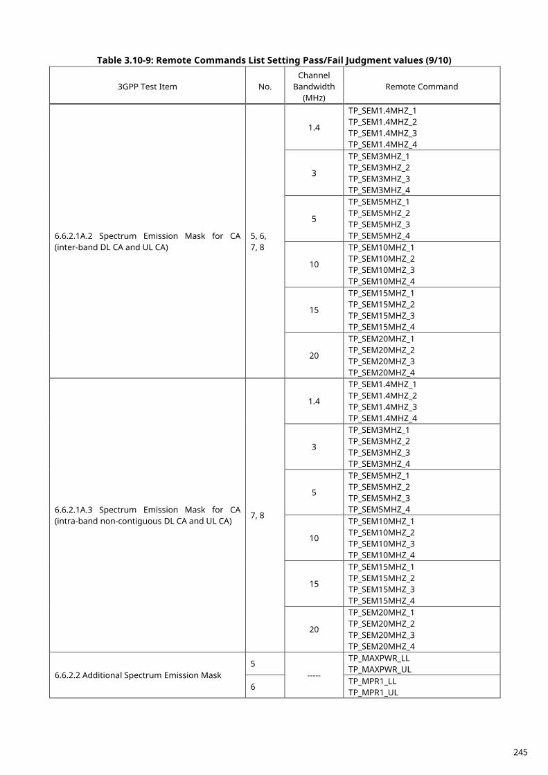
Table 3.10-9: Remote Commands List Setting Pass/Fail Judgment values (9/10)
3GPP Test Item No. Channel
Bandwidth (MHz)
Remote Command
6.6.2.1A.2 Spectrum Emission Mask for CA (inter-band DL CA and UL CA)
5, 6, 7, 8
1.4
TP_SEM1.4MHZ_1 TP_SEM1.4MHZ_2 TP_SEM1.4MHZ_3 TP_SEM1.4MHZ_4
3
TP_SEM3MHZ_1 TP_SEM3MHZ_2 TP_SEM3MHZ_3 TP_SEM3MHZ_4
5
TP_SEM5MHZ_1 TP_SEM5MHZ_2 TP_SEM5MHZ_3 TP_SEM5MHZ_4
10
TP_SEM10MHZ_1 TP_SEM10MHZ_2 TP_SEM10MHZ_3 TP_SEM10MHZ_4
15
TP_SEM15MHZ_1 TP_SEM15MHZ_2 TP_SEM15MHZ_3 TP_SEM15MHZ_4
20
TP_SEM20MHZ_1 TP_SEM20MHZ_2 TP_SEM20MHZ_3 TP_SEM20MHZ_4
6.6.2.1A.3 Spectrum Emission Mask for CA (intra-band non-contiguous DL CA and UL CA)
7, 8
1.4
TP_SEM1.4MHZ_1 TP_SEM1.4MHZ_2 TP_SEM1.4MHZ_3 TP_SEM1.4MHZ_4
3
TP_SEM3MHZ_1 TP_SEM3MHZ_2 TP_SEM3MHZ_3 TP_SEM3MHZ_4
5
TP_SEM5MHZ_1 TP_SEM5MHZ_2 TP_SEM5MHZ_3 TP_SEM5MHZ_4
10
TP_SEM10MHZ_1 TP_SEM10MHZ_2 TP_SEM10MHZ_3 TP_SEM10MHZ_4
15
TP_SEM15MHZ_1 TP_SEM15MHZ_2 TP_SEM15MHZ_3 TP_SEM15MHZ_4
20
TP_SEM20MHZ_1 TP_SEM20MHZ_2 TP_SEM20MHZ_3 TP_SEM20MHZ_4
6.6.2.2 Additional Spectrum Emission Mask 5
-----
TP_MAXPWR_LL TP_MAXPWR_UL
6 TP_MPR1_LL TP_MPR1_UL
245
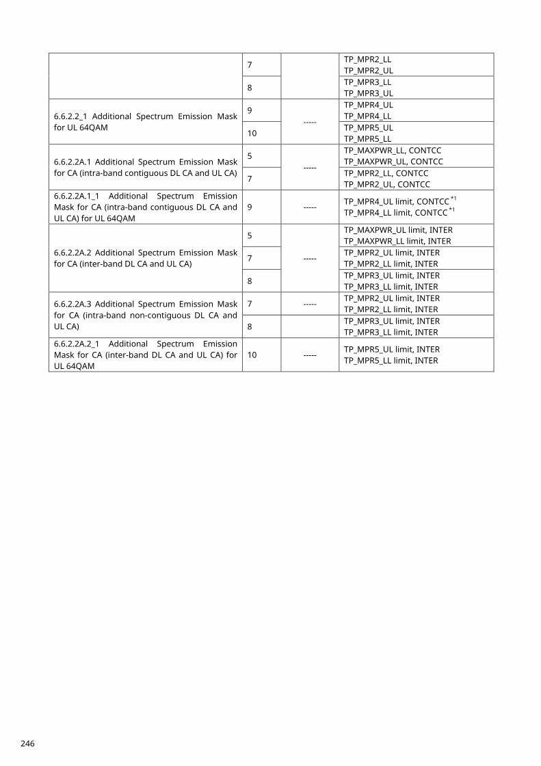
7 TP_MPR2_LL TP_MPR2_UL
8 TP_MPR3_LL TP_MPR3_UL
6.6.2.2_1 Additional Spectrum Emission Mask for UL 64QAM
9 -----
TP_MPR4_UL TP_MPR4_LL
10 TP_MPR5_UL TP_MPR5_LL
6.6.2.2A.1 Additional Spectrum Emission Mask for CA (intra-band contiguous DL CA and UL CA)
5 -----
TP_MAXPWR_LL, CONTCC TP_MAXPWR_UL, CONTCC
7 TP_MPR2_LL, CONTCC TP_MPR2_UL, CONTCC
6.6.2.2A.1_1 Additional Spectrum Emission Mask for CA (intra-band contiguous DL CA and UL CA) for UL 64QAM
9 ----- TP_MPR4_UL limit, CONTCC *1 TP_MPR4_LL limit, CONTCC *1
6.6.2.2A.2 Additional Spectrum Emission Mask for CA (inter-band DL CA and UL CA)
5
-----
TP_MAXPWR_UL limit, INTER TP_MAXPWR_LL limit, INTER
7 TP_MPR2_UL limit, INTER TP_MPR2_LL limit, INTER
8 TP_MPR3_UL limit, INTER TP_MPR3_LL limit, INTER
6.6.2.2A.3 Additional Spectrum Emission Mask for CA (intra-band non-contiguous DL CA and UL CA)
7 ----- TP_MPR2_UL limit, INTER TP_MPR2_LL limit, INTER
8 TP_MPR3_UL limit, INTER TP_MPR3_LL limit, INTER
6.6.2.2A.2_1 Additional Spectrum Emission Mask for CA (inter-band DL CA and UL CA) for UL 64QAM
10 ----- TP_MPR5_UL limit, INTER TP_MPR5_LL limit, INTER
246
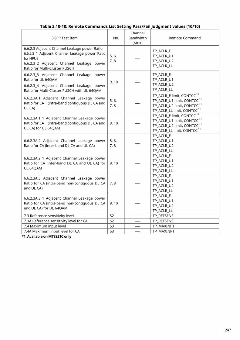
Table 3.10-10: Remote Commands List Setting Pass/Fail Judgment values (10/10)
3GPP Test Item No. Channel
Bandwidth (MHz)
Remote Command
6.6.2.3 Adjacent Channel Leakage power Ratio 6.6.2.3_1 Adjacent Channel Leakage power Ratio for HPUE 6.6.2.3_2 Adjacent Channel Leakage power Ratio for Multi-Cluster PUSCH
5, 6, 7, 8
-----
TP_ACLR_E TP_ACLR_U1 TP_ACLR_U2 TP_ACLR_LL
6.6.2.3_3 Adjacent Channel Leakage power Ratio for UL 64QAM
6.6.2.3_4 Adjacent Channel Leakage power Ratio for Multi-Cluster PUSCH with UL 64QAM
9, 10 -----
TP_ACLR_E TP_ACLR_U1 TP_ACLR_U2 TP_ACLR_LL
6.6.2.3A.1 Adjacent Channel Leakage power Ratio for CA (intra-band contiguous DL CA and UL CA)
5, 6, 7, 8
-----
TP_ACLR_E limit, CONTCC *1 TP_ACLR_U1 limit, CONTCC *1 TP_ACLR_U2 limit, CONTCC *1 TP_ACLR_LL limit, CONTCC *1
6.6.2.3A.1_1 Adjacent Channel Leakage power Ratio for CA (intra-band contiguous DL CA and UL CA) for UL 64QAM
9, 10 -----
TP_ACLR_E limit, CONTCC *1 TP_ACLR_U1 limit, CONTCC *1 TP_ACLR_U2 limit, CONTCC *1 TP_ACLR_LL limit, CONTCC *1
6.6.2.3A.2 Adjacent Channel Leakage power Ratio for CA (inter-band DL CA and UL CA)
5, 6, 7, 8
-----
TP_ACLR_E TP_ACLR_U1 TP_ACLR_U2 TP_ACLR_LL
6.6.2.3A.2_1 Adjacent Channel Leakage power Ratio for CA (inter-band DL CA and UL CA) for UL 64QAM
9, 10 -----
TP_ACLR_E TP_ACLR_U1 TP_ACLR_U2 TP_ACLR_LL
6.6.2.3A.3 Adjacent Channel Leakage power Ratio for CA (intra-band non-contiguous DL CA and UL CA)
7, 8 -----
TP_ACLR_E TP_ACLR_U1 TP_ACLR_U2 TP_ACLR_LL
6.6.2.3A.3_1 Adjacent Channel Leakage power Ratio for CA (intra-band non-contiguous DL CA and UL CA) for UL 64QAM
9, 10 -----
TP_ACLR_E TP_ACLR_U1 TP_ACLR_U2 TP_ACLR_LL
7.3 Reference sensitivity level 52 ----- TP_REFSENS 7.3A Reference sensitivity level for CA 52 ----- TP_REFSENS 7.4 Maximum input level 53 ----- TP_MAXINPT 7.4A Maximum input level for CA 53 ----- TP_MAXINPT
*1: Available on MT8821C only
247
SRS (Sounding Reference Signal) Measurements 3.11.This chapter describes an example of Tx measurement with SRS (Sounding Reference Signal). After setting SRS config, measure using the same procedure as described in section 3.1 TX Measurements.
1. Execute SRS ON to set SRS config to On. 2. Perform the LTE connection. (2.1.2, 2.1.3, 2.1.4) 3. Measure using the same procedure as described in 3.1 TX Measurements. (NOTE 1, NOTE 2)
NOTE 1: Power measurement, OBW, SEM, ACLR and Modulation Analysis are supported.
The measurement subframe is SRS transmission subframe. Power measurement and OBW includes SRS symbol(s). Modulation Analysis excludes SRS symbol(s). Modulation Analysis of SRS itself is not supported.
NOTE 2: SRS in CA condition is not supported yet.
248
RX Measurements for CA including LAA SCell 3.12.This feature is supported only by the MT8821C. Details of the LAA feature are described in section 12. LAA (MT8821C Only).
Reference sensitivity level for CA 3.12.1.This example describes 3DL with Intra-band contiguous + Inter-band CA combination including LAA SCell (Band46). For other CA conditions including LAA, refer to each procedure (section 3.4 to 3.6) and add step 2 of the following procedure. Example: PCC DL Channel = 300 (Band1), SCC1 DL Channel = 50665 (Band46),
SCC2 DL Channel = 50863 (Band46) Highest NRB_agg, PCC NRB = 100, SCC1 NRB = 100, SCC2 NRB = 100, PCC and SCC1 and SCC2 DL allocations (LCRB@RBstart) are P_100@0 and S1_100@0 and S2_100@0, respectively. PCC UL allocations (LCRB@RBstart) are P_100@0.
1. Execute TESTPRM RX_SENS to set Test Parameter to RX – Ref. Sens./Freq. Error. 2. Execute LAAPAT RX_SENSE to set Call Processing Parameter – Carrier Aggregation – LAA Scheduling
Pattern to Reference Sense. 3. Execute TPUT SAMPLE 10000 to set Rx Measurement Parameter – Throughput – Number of Sample to
10000. 4. Execute TPUT_EARLY ON to set Rx Measurement Parameter – Throughput – Early Decision to On. 5. Execute TPUT_EARLY_TARCC EACH to set Rx Measurement Parameter - Target CC to Each. 6. Execute TPUT_EARLY_EACH ON,ON,ON,OFF,OFF to set Rx Measurement Parameter - PCC, Rx
Measurement Parameter – SCC-1 and Rx Measurement Parameter - SCC-2 to On. 7. Execute SWP to measure the Throughput. 8. Execute TPUT? PER to read the Throughput measurement result (%) 9. Execute TPUTPASS? to check that the Throughput measurement Pass/Fail judgment is Pass.
NOTE 1: MT8821C-019 option is required when testing for LAA Band.
Maximum input level for CA 3.12.2.This example describes 4DL with Intra-band contiguous + Inter-band CA combination including LAA SCell (Band46). For other CA conditions including LAA, refer to each procedure (section 3.4 to 3.6) and add step 2 of the following procedure. Example: PCC DL Channel = 300 (Band1), SCC1 DL Channel = 3100 (Band7),
SCC2 DL Channel = 50665 (Band46), SCC3 DL Channel = 50863 (Band46) Highest NRB_agg, PCC NRB = 100, SCC1 NRB = 100, SCC2 NRB = 100, SCC3 NRB = 100, PCC and SCC1 and SCC2 and SCC3 DL allocations (LCRB@RBstart) are P_100@0 and S1_100@0 and S2_100@0, S3_100@0 respectively. PCC UL allocations (LCRB@RBstart) are P_100@0.
1. Execute TESTPRM RX_MAX to set Test Parameter to RX – MAX. Input Level. 2. Execute LAAPAT RX_SENSE to set Call Processing Parameter – Carrier Aggregation – LAA Scheduling
Pattern to Reference Sense. 3. Execute TPUT SAMPLE 10000 to set Rx Measurement Parameter – Throughput – Number of Sample to
10000. 4. Execute TPUT_EARLY ON to set Rx Measurement Parameter – Throughput – Early Decision to On. 5. Execute TPUT_EARLY_TARCC EACH to set Rx Measurement Parameter – Throughput – Early Decision -
Target CC to Each. 6. Execute TPUT_EARLY_EACH OFF,OFF,ON,ON,OFF to set Rx Measurement Parameter – Throughput –
Early Decision - Target CC – SCC-2/SCC-3 to On. 7. Execute SWP to measure the Throughput. 8. Execute TPUT? PER to read the Throughput measurement result (%)
249

9. Execute TPUTPASS? to check that the Throughput measurement Pass/Fail judgment is Pass.
NOTE 1: MT8821C-019 option is required when testing for LAA Band.
250
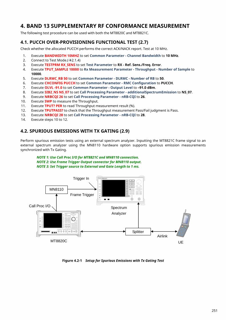
BAND 13 SUPPLEMENTARY RF CONFORMANCE MEASUREMENT 4.The following test procedure can be used with both the MT8820C and MT8821C.
PUCCH OVER-PROVISIONING FUNCTIONAL TEST (2.7) 4.1.Check whether the allocated PUCCH performs the correct ACK/NACK report. Test at 10 MHz.
1. Execute BANDWIDTH 10MHZ to set Common Parameter - Channel Bandwidth to 10 MHz. 2. Connect to Test Mode.(2.1.4) 3. Execute TESTPRM RX_SENS to set Test Parameter to RX - Ref. Sens./Freq. Error. 4. Execute TPUT_SAMPLE 10000 to Rx Measurement Parameter - Throughput - Number of Sample to
10000. 5. Execute DLRMC_RB 50 to set Common Parameter - DLRMC - Number of RB to 50. 6. Execute CHCONFIG PUCCH to set Common Parameter - RMC Configuration to PUCCH. 7. Execute OLVL -91.0 to set Common Parameter - Output Level to –91.0 dBm. 8. Execute SIB2_NS NS_07 to set Call Processing Parameter - additionalSpectrumEmission to NS_07. 9. Execute NRBCQI 26 to set Call Processing Parameter - nRB-CQI to 26.
10. Execute SWP to measure the Throughput. 11. Execute TPUT? PER to read Throughput measurement result (%). 12. Execute TPUTPASS? to check that the Throughput measurement Pass/Fail judgment is Pass. 13. Execute NRBCQI 28 to set Call Processing Parameter - nRB-CQI to 28. 14. Execute steps 10 to 12.
SPURIOUS EMISSIONS WITH TX GATING (2.9) 4.2. Perform spurious emission tests using an external spectrum analyzer. Inputting the MT8821C frame signal to an external spectrum analyzer using the MN8110 hardware option supports spurious emission measurements synchronized with Tx Gating. NOTE 1: Use Call Proc I/O for MT8821C and MN8110 connection. NOTE 2: Use Frame Trigger Output connector for MN8110 output. NOTE 3: Set Trigger source to External and Gate Length to 1 ms.
Frame Trigger
MT8820C UE Airlink
Spectrum Analyzer
MN8110
Splitter
Call Proc I/O
Trigger In MS2691 Anritsu
Figure 4.2-1 Setup for Spurious Emissions with Tx Gating Test
251
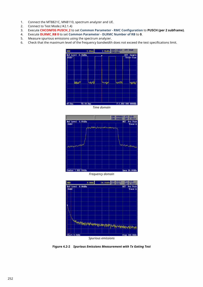
1. Connect the MT8821C, MN8110, spectrum analyzer and UE. 2. Connect to Test Mode.(2.1.4) 3. Execute CHCONFIG PUSCH_2 to set Common Parameter - RMC Configuration to PUSCH (per 2 subframe). 4. Execute DLRMC_RB 0 to set Common Parameter - DLRMC Number of RB to 0. 5. Measure spurious emissions using the spectrum analyzer. 6. Check that the maximum level of the frequency bandwidth does not exceed the test specifications limit.
Time domain
Frequency domain
Spurious emissions
Figure 4.2-2 Spurious Emissions Measurement with Tx Gating Test
252
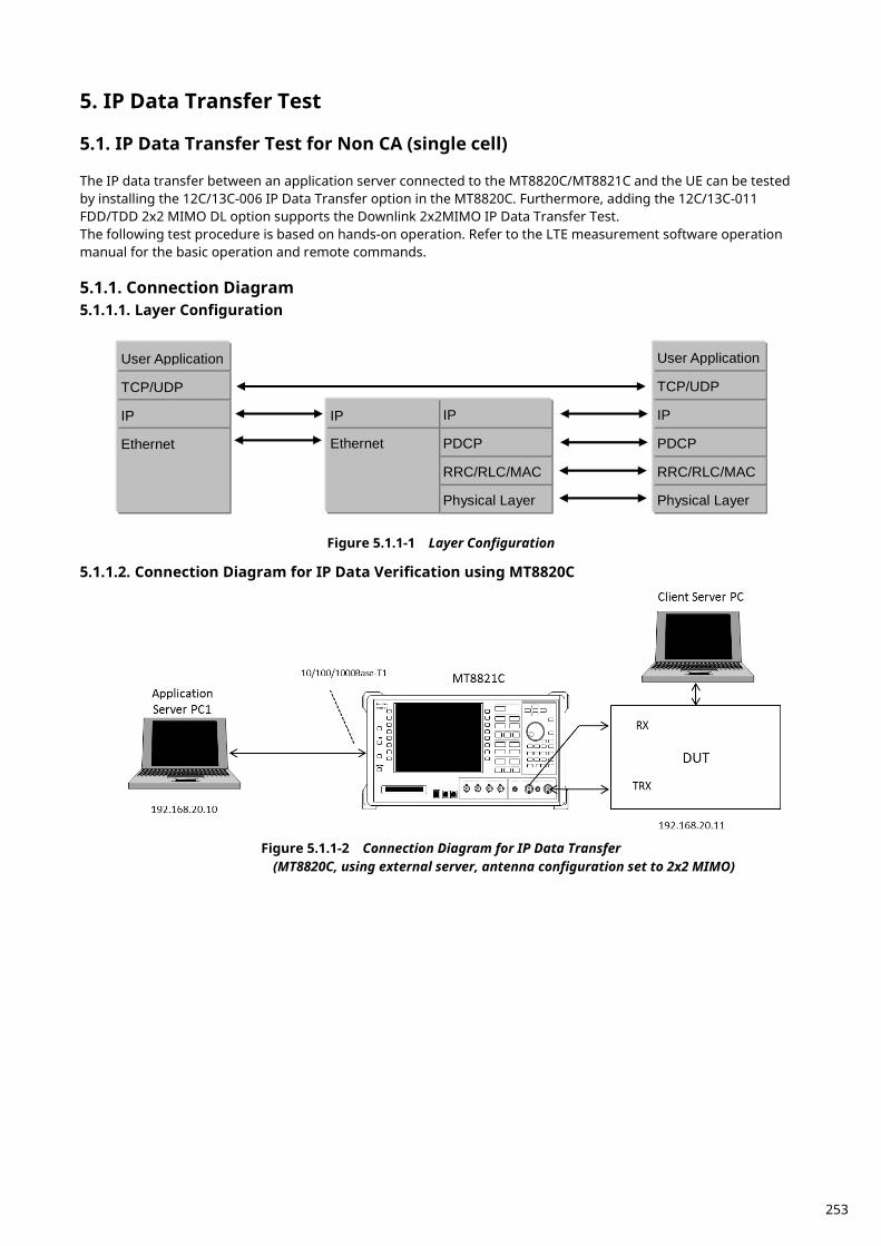
IP Data Transfer Test 5.
IP Data Transfer Test for Non CA (single cell) 5.1. The IP data transfer between an application server connected to the MT8820C/MT8821C and the UE can be tested by installing the 12C/13C-006 IP Data Transfer option in the MT8820C. Furthermore, adding the 12C/13C-011 FDD/TDD 2x2 MIMO DL option supports the Downlink 2x2MIMO IP Data Transfer Test. The following test procedure is based on hands-on operation. Refer to the LTE measurement software operation manual for the basic operation and remote commands.
Connection Diagram 5.1.1.5.1.1.1. Layer Configuration
Ethernet
IP
TCP/UDP
User Application
Physical Layer
RRC/RLC/MAC
PDCP
IP
Physical Layer
RRC/RLC/MAC
PDCP
IP
Ethernet
IP
TCP/UDP
User Application
Figure 5.1.1-1 Layer Configuration
5.1.1.2. Connection Diagram for IP Data Verification using MT8820C
Figure 5.1.1-2 Connection Diagram for IP Data Transfer
(MT8820C, using external server, antenna configuration set to 2x2 MIMO)
253
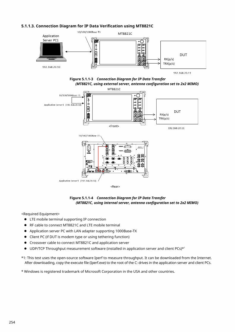
5.1.1.3. Connection Diagram for IP Data Verification using MT8821C
Figure 5.1.1-3 Connection Diagram for IP Data Transfer (MT8821C, using external server, antenna configuration set to 2x2 MIMO)
Figure 5.1.1-4 Connection Diagram for IP Data Transfer (MT8821C, using internal server, antenna configuration set to 2x2 MIMO)
<Required Equipment> LTE mobile terminal supporting IP connection
RF cable to connect MT8821C and LTE mobile terminal
Application server PC with LAN adapter supporting 1000Base-TX Client PC (if DUT is modem type or using tethering function)
Crossover cable to connect MT8821C and application server
UDP/TCP Throughput measurement software (installed in application server and client PCs)*1
*1: This test uses the open-source software Iperf to measure throughput. It can be downloaded from the Internet. After downloading, copy the execute file (Iperf.exe) to the root of the C: drives in the application server and client PCs.
* Windows is registered trademark of Microsoft Corporation in the USA and other countries.
254
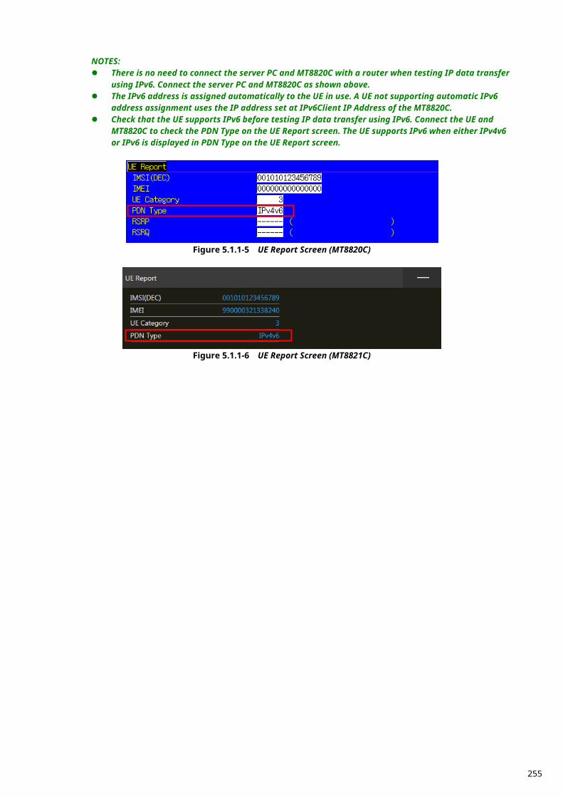
NOTES: There is no need to connect the server PC and MT8820C with a router when testing IP data transfer
using IPv6. Connect the server PC and MT8820C as shown above. The IPv6 address is assigned automatically to the UE in use. A UE not supporting automatic IPv6
address assignment uses the IP address set at IPv6Client IP Address of the MT8820C. Check that the UE supports IPv6 before testing IP data transfer using IPv6. Connect the UE and
MT8820C to check the PDN Type on the UE Report screen. The UE supports IPv6 when either IPv4v6 or IPv6 is displayed in PDN Type on the UE Report screen.
Figure 5.1.1-5 UE Report Screen (MT8820C)
Figure 5.1.1-6 UE Report Screen (MT8821C)
255
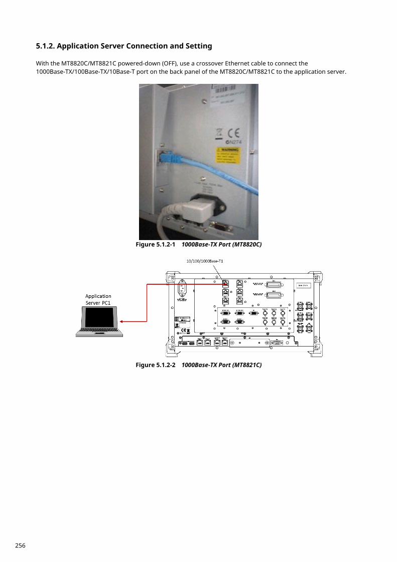
Application Server Connection and Setting 5.1.2. With the MT8820C/MT8821C powered-down (OFF), use a crossover Ethernet cable to connect the 1000Base-TX/100Base-TX/10Base-T port on the back panel of the MT8820C/MT8821C to the application server.
Figure 5.1.2-1 1000Base-TX Port (MT8820C)
Figure 5.1.2-2 1000Base-TX Port (MT8821C)
256
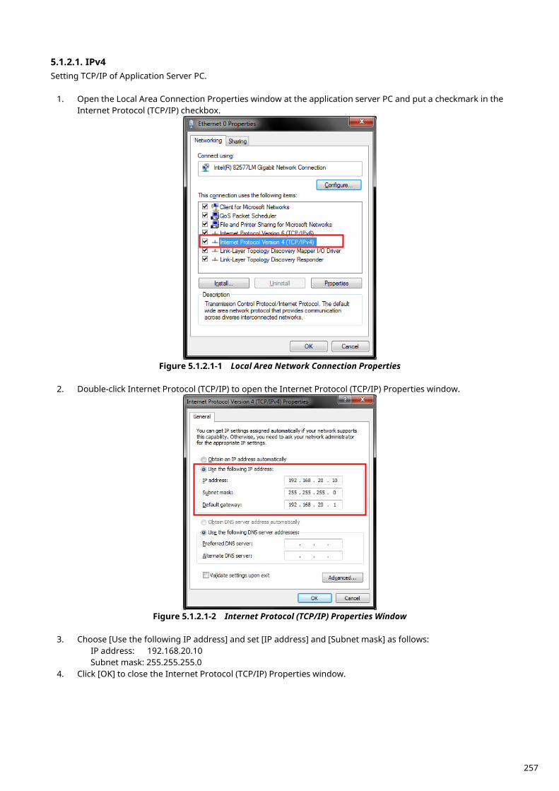
5.1.2.1. IPv4 Setting TCP/IP of Application Server PC.
1. Open the Local Area Connection Properties window at the application server PC and put a checkmark in the Internet Protocol (TCP/IP) checkbox.
Figure 5.1.2.1-1 Local Area Network Connection Properties
2. Double-click Internet Protocol (TCP/IP) to open the Internet Protocol (TCP/IP) Properties window.
Figure 5.1.2.1-2 Internet Protocol (TCP/IP) Properties Window
3. Choose [Use the following IP address] and set [IP address] and [Subnet mask] as follows:
IP address: 192.168.20.10 Subnet mask: 255.255.255.0
4. Click [OK] to close the Internet Protocol (TCP/IP) Properties window.
257
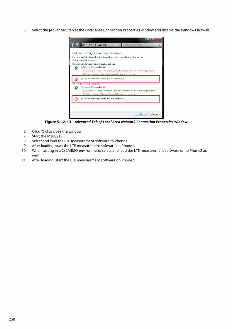
5. Select the [Advanced] tab at the Local Area Connection Properties window and disable the Windows firewall.
Figure 5.1.2.1-3 Advanced Tab of Local Area Network Connection Properties Window
6. Click [OK] to close the window. 7. Start the MT8821C. 8. Select and load the LTE measurement software to Phone1. 9. After loading, start the LTE measurement software on Phone1.
10. When testing in a 2x2MIMO environment, select and load the LTE measurement software on to Phone2 as well.
11. After loading, start the LTE measurement software on Phone2.
258
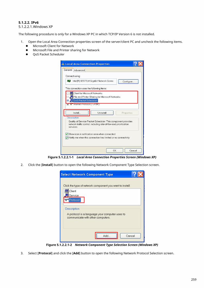
5.1.2.2. IPv6 5.1.2.2.1. Windows XP The following procedure is only for a Windows XP PC in which TCP/IP Version 6 is not installed.
1. Open the Local Area Connection properties screen of the server/client PC and uncheck the following items. Microsoft Client for Network Microsoft File and Printer sharing for Network QoS Packet Scheduler
Figure 5.1.2.2.1-1 Local Area Connection Properties Screen (Windows XP)
2. Click the [Install] button to open the following Network Component Type Selection screen.
Figure 5.1.2.2.1-2 Network Component Type Selection Screen (Windows XP)
3. Select [Protocol] and click the [Add] button to open the following Network Protocol Selection screen.
259
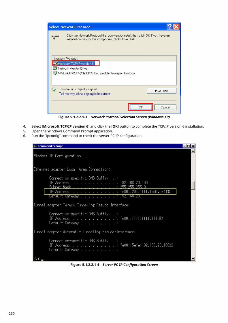
Figure 5.1.2.2.1-3 Network Protocol Selection Screen (Windows XP)
4. Select [Microsoft TCP/IP version 6] and click the [OK] button to complete the TCP/IP version 6 installation. 5. Open the Windows Command Prompt application. 6. Run the “ipconfig” command to check the server PC IP configuration.
Figure 5.1.2.2.1-4 Server PC IP Configuration Screen
260

7. Run the “netsh int ipv6 show int” command and confirm the Index No. (Idx) allocated to the Local Area
Connection. This Index No. is required at the next step to set the IP address.
Figure 5.1.2.2.1-5 Query Result for Index No. Screen
8. Run the “netsh int ipv6 set address 5 2001::2” command to set the IP address.
The IP address set by this procedure is set to match the address set at [IPV6 Server IP Address] of the MT8821C.
NOTE: Places with contiguous 0s in the IPv6 Server IP Address captured at Index No IP Address of step 4 ‘netsh
int ipv6 set’ are abbreviated as::. For example IPv6 Server IP Address 2001:0000:0000:0000:0000:0000:0000:0002 displayed in the following screen is abbreviated to 2001::2.
Figure 5.1.2.2.1-6 IPv6 Address Setting Screen
9. Run the “ipconfig” command again to check that the IP address set at step 5 has been set correctly.
261
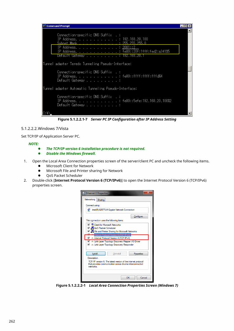
Figure 5.1.2.2.1-7 Server PC IP Configuration after IP Address Setting
5.1.2.2.2. Windows 7/Vista Set TCP/IP of Application Server PC.
NOTE: The TCP/IP version 6 installation procedure is not required. Disable the Windows firewall.
1. Open the Local Area Connection properties screen of the server/client PC and uncheck the following items.
Microsoft Client for Network Microsoft File and Printer sharing for Network QoS Packet Scheduler
2. Double-click [Internet Protocol Version 6 (TCP/IPv6)] to open the Internet Protocol Version 6 (TCP/IPv6) properties screen.
Figure 5.1.2.2.2-1 Local Area Connection Properties Screen (Windows 7)
262
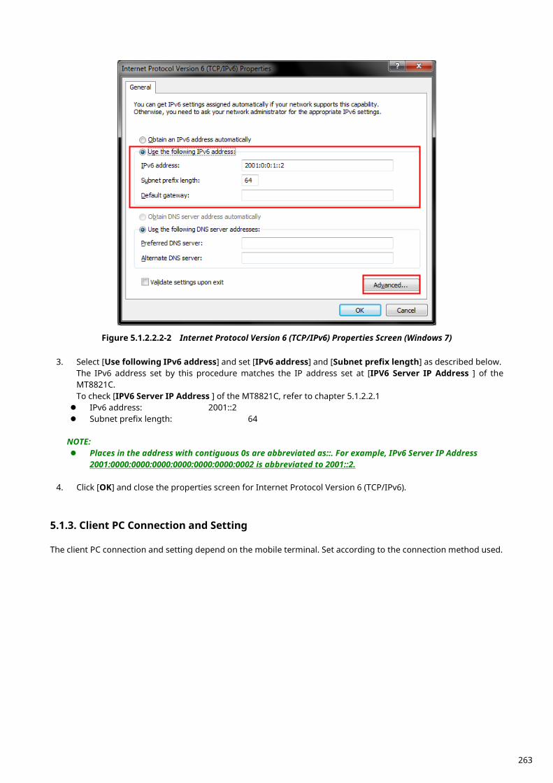
Figure 5.1.2.2.2-2 Internet Protocol Version 6 (TCP/IPv6) Properties Screen (Windows 7)
3. Select [Use following IPv6 address] and set [IPv6 address] and [Subnet prefix length] as described below. The IPv6 address set by this procedure matches the IP address set at [IPV6 Server IP Address ] of the MT8821C. To check [IPV6 Server IP Address ] of the MT8821C, refer to chapter 5.1.2.2.1 IPv6 address: 2001::2 Subnet prefix length: 64
NOTE: Places in the address with contiguous 0s are abbreviated as::. For example, IPv6 Server IP Address
2001:0000:0000:0000:0000:0000:0000:0002 is abbreviated to 2001::2.
4. Click [OK] and close the properties screen for Internet Protocol Version 6 (TCP/IPv6).
Client PC Connection and Setting 5.1.3. The client PC connection and setting depend on the mobile terminal. Set according to the connection method used.
263
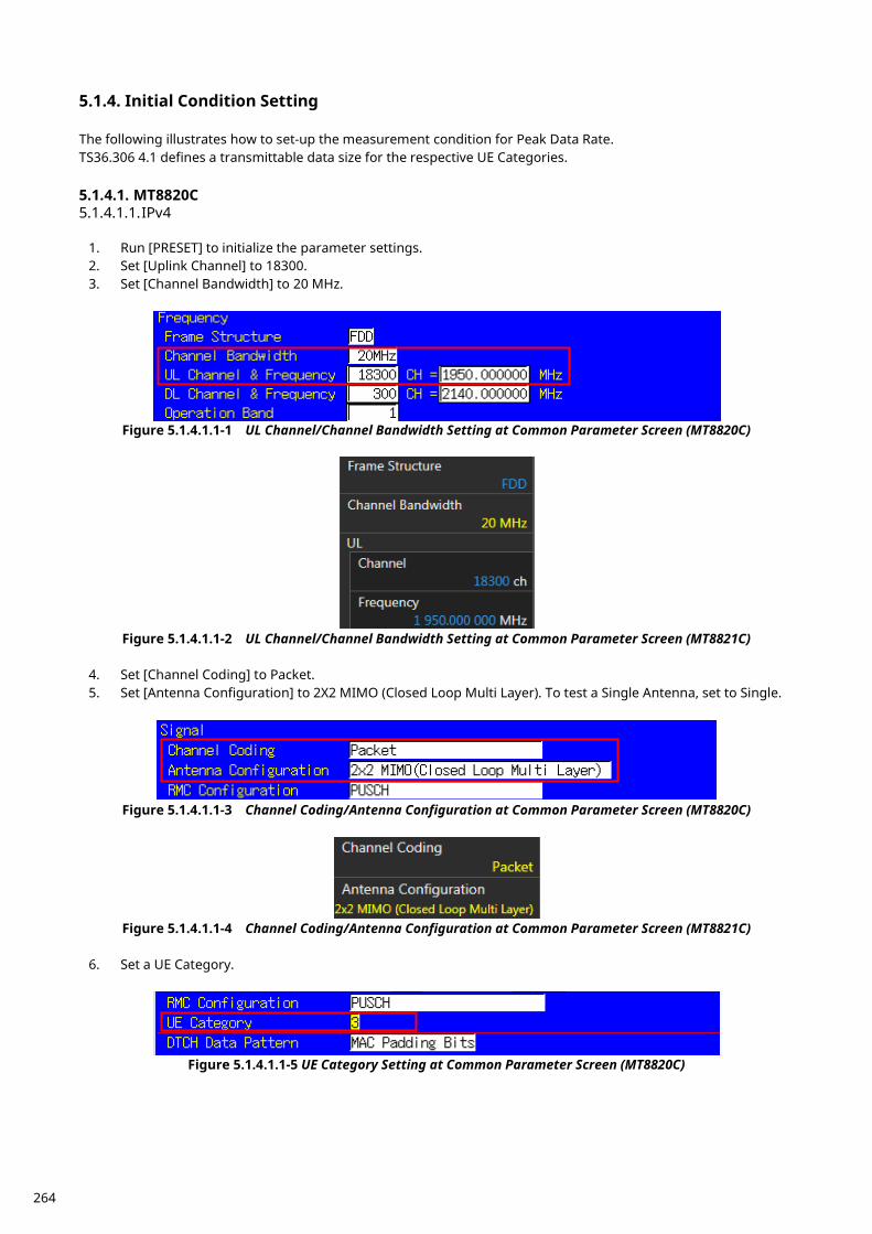
Initial Condition Setting 5.1.4. The following illustrates how to set-up the measurement condition for Peak Data Rate. TS36.306 4.1 defines a transmittable data size for the respective UE Categories. 5.1.4.1. MT8820C 5.1.4.1.1. IPv4
1. Run [PRESET] to initialize the parameter settings. 2. Set [Uplink Channel] to 18300. 3. Set [Channel Bandwidth] to 20 MHz.
Figure 5.1.4.1.1-1 UL Channel/Channel Bandwidth Setting at Common Parameter Screen (MT8820C)
Figure 5.1.4.1.1-2 UL Channel/Channel Bandwidth Setting at Common Parameter Screen (MT8821C)
4. Set [Channel Coding] to Packet. 5. Set [Antenna Configuration] to 2X2 MIMO (Closed Loop Multi Layer). To test a Single Antenna, set to Single.
Figure 5.1.4.1.1-3 Channel Coding/Antenna Configuration at Common Parameter Screen (MT8820C)
Figure 5.1.4.1.1-4 Channel Coding/Antenna Configuration at Common Parameter Screen (MT8821C)
6. Set a UE Category.
Figure 5.1.4.1.1-5 UE Category Setting at Common Parameter Screen (MT8820C)
264
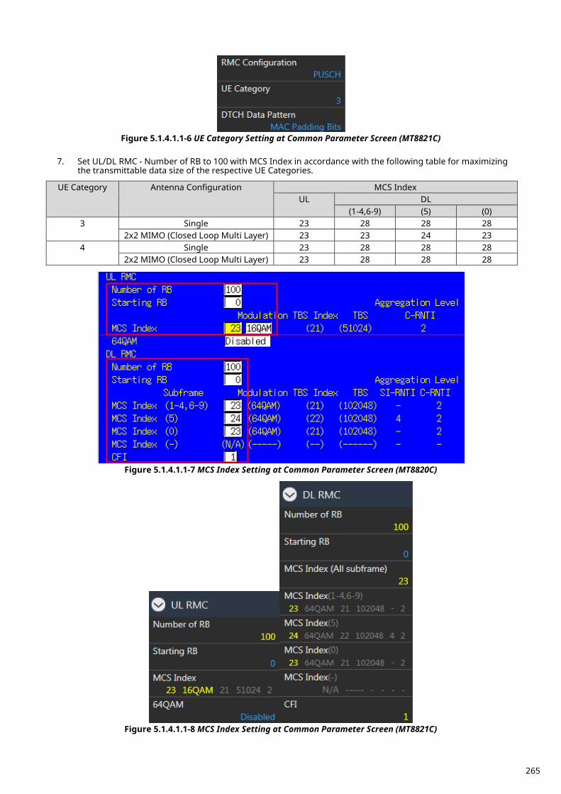
Figure 5.1.4.1.1-6 UE Category Setting at Common Parameter Screen (MT8821C)
7. Set UL/DL RMC - Number of RB to 100 with MCS Index in accordance with the following table for maximizing
the transmittable data size of the respective UE Categories.
UE Category Antenna Configuration MCS Index UL DL
(1-4,6-9) (5) (0) 3 Single 23 28 28 28
2x2 MIMO (Closed Loop Multi Layer) 23 23 24 23 4 Single 23 28 28 28
2x2 MIMO (Closed Loop Multi Layer) 23 28 28 28
Figure 5.1.4.1.1-7 MCS Index Setting at Common Parameter Screen (MT8820C)
Figure 5.1.4.1.1-8 MCS Index Setting at Common Parameter Screen (MT8821C)
265
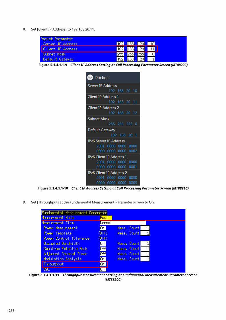
8. Set [Client IP Address] to 192.168.20.11.
Figure 5.1.4.1.1-9 Client IP Address Setting at Call Processing Parameter Screen (MT8820C)
Figure 5.1.4.1.1-10 Client IP Address Setting at Call Processing Parameter Screen (MT8821C)
9. Set [Throughput] at the Fundamental Measurement Parameter screen to On.
Figure 5.1.4.1.1-11 Throughput Measurement Setting at Fundamental Measurement Parameter Screen
(MT8820C)
266
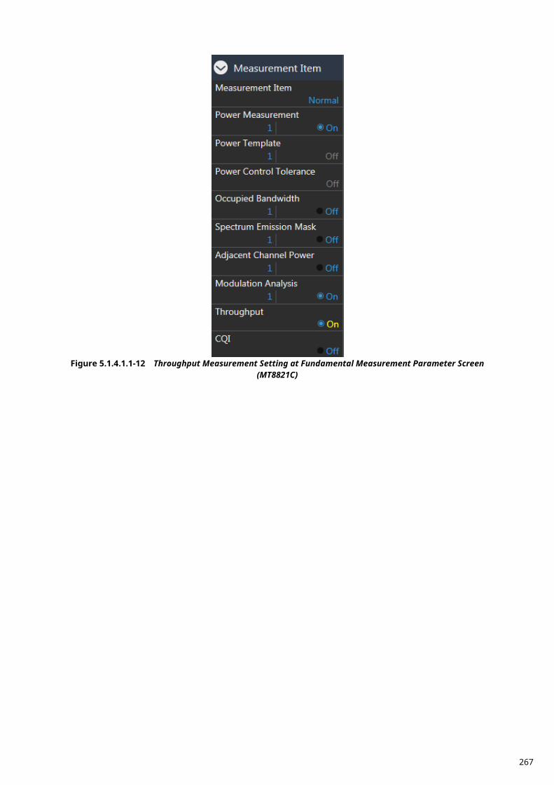
Figure 5.1.4.1.1-12 Throughput Measurement Setting at Fundamental Measurement Parameter Screen
(MT8821C)
267

5.1.4.1.2. IPv6 This measurement can be performed using the same procedure as in Chapter 5.1.4.1.1, by substituting the following steps.
8. Set [IPv6 Server IP Address] to 2001::2. 9. Set [IPv6 Client IP Address] to 2001::1.
Figure 5.1.4.1.2-1 IPv6 Address Setting at Call Processing Parameter Screen (MT8820C)
Figure 5.1.4.1.2-2 IPv6 Address Setting at Call Processing Parameter Screen (MT8821C)
268
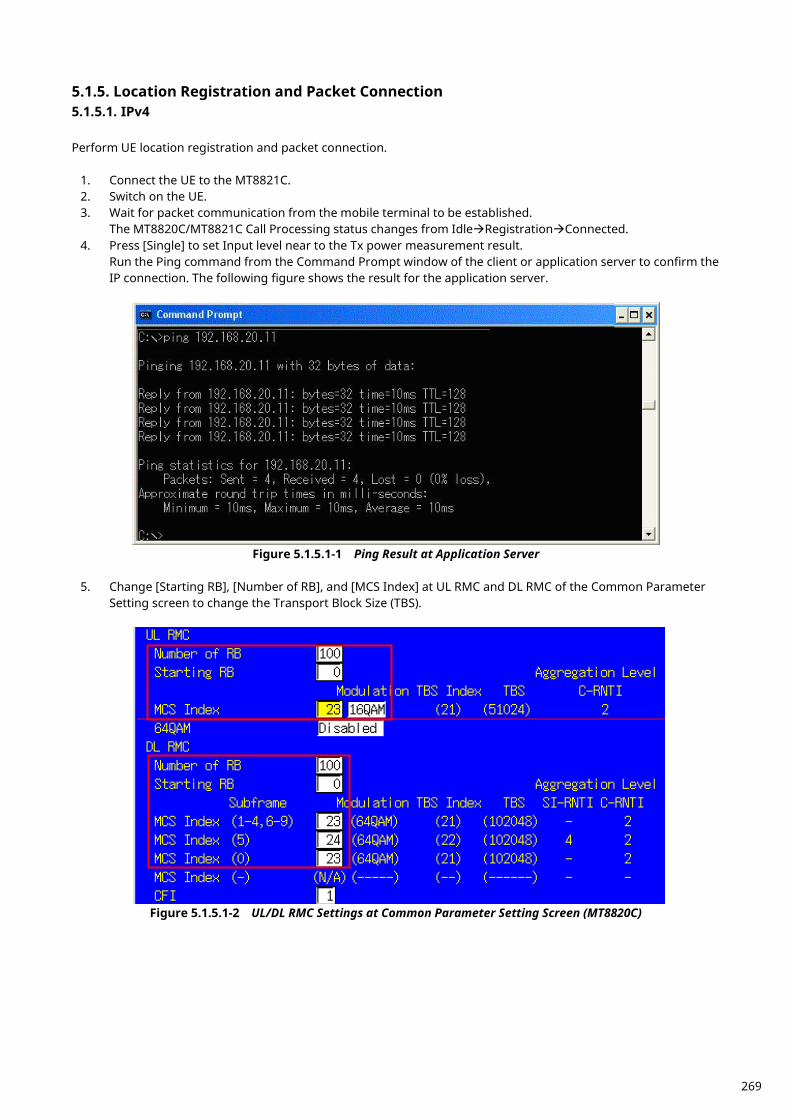
Location Registration and Packet Connection 5.1.5.5.1.5.1. IPv4 Perform UE location registration and packet connection.
1. Connect the UE to the MT8821C. 2. Switch on the UE. 3. Wait for packet communication from the mobile terminal to be established.
The MT8820C/MT8821C Call Processing status changes from IdleRegistrationConnected. 4. Press [Single] to set Input level near to the Tx power measurement result.
Run the Ping command from the Command Prompt window of the client or application server to confirm the IP connection. The following figure shows the result for the application server.
Figure 5.1.5.1-1 Ping Result at Application Server
5. Change [Starting RB], [Number of RB], and [MCS Index] at UL RMC and DL RMC of the Common Parameter
Setting screen to change the Transport Block Size (TBS).
Figure 5.1.5.1-2 UL/DL RMC Settings at Common Parameter Setting Screen (MT8820C)
269
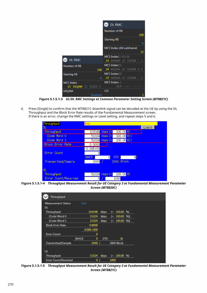
Figure 5.1.5.1-3 UL/DL RMC Settings at Common Parameter Setting Screen (MT8821C)
6. Press [Single] to confirm that the MT8821C downlink signal can be decoded at the UE by using the DL
Throughput and the Block Error Rate results of the Fundamental Measurement screen. If there is an error, change the RMC settings or Level setting, and repeat steps 5 and 6.
Figure 5.1.5.1-4 Throughput Measurement Result for UE Category 3 at Fundamental Measurement Parameter
Screen (MT8820C)
Figure 5.1.5.1-5 Throughput Measurement Result for UE Category 3 at Fundamental Measurement Parameter
Screen (MT8821C)
270
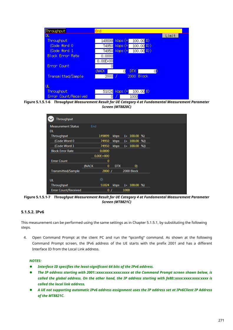
Figure 5.1.5.1-6 Throughput Measurement Result for UE Category 4 at Fundamental Measurement Parameter
Screen (MT8820C)
Figure 5.1.5.1-7 Throughput Measurement Result for UE Category 4 at Fundamental Measurement Parameter
Screen (MT8821C)
5.1.5.2. IPv6 This measurement can be performed using the same settings as in Chapter 5.1.5.1, by substituting the following steps.
4. Open Command Prompt at the client PC and run the “ipconfig” command. As shown at the following
Command Prompt screen, the IPv6 address of the UE starts with the prefix 2001 and has a different Interface ID from the Local Link address.
NOTES: Interface ID specifies the least-significant 64 bits of the IPv6 address. The IP address starting with 2001::xxxx:xxxx:xxxx:xxxx at the Command Prompt screen shown below, is
called the global address. On the other hand, the IP address starting with fe80::xxxx:xxxx:xxxx:xxxx is called the local link address.
A UE not supporting automatic IPv6 address assignment uses the IP address set at IPv6Client IP Address of the MT8821C.
271
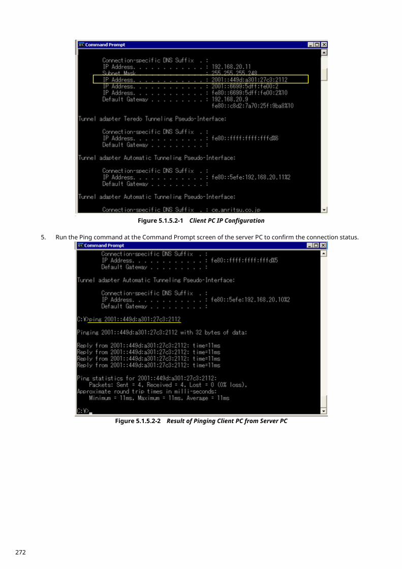
Figure 5.1.5.2-1 Client PC IP Configuration
5. Run the Ping command at the Command Prompt screen of the server PC to confirm the connection status.
Figure 5.1.5.2-2 Result of Pinging Client PC from Server PC
272
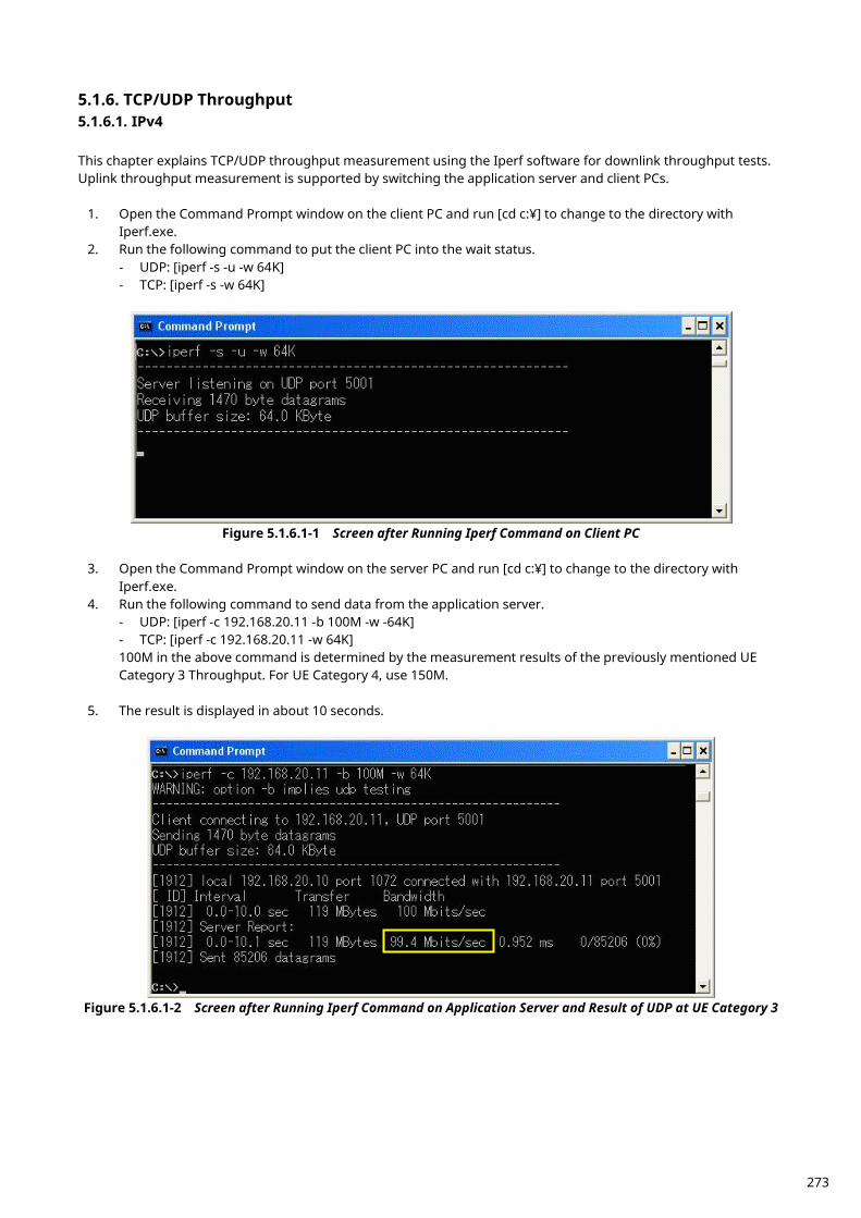
TCP/UDP Throughput 5.1.6.5.1.6.1. IPv4 This chapter explains TCP/UDP throughput measurement using the Iperf software for downlink throughput tests. Uplink throughput measurement is supported by switching the application server and client PCs.
1. Open the Command Prompt window on the client PC and run [cd c:¥] to change to the directory with Iperf.exe.
2. Run the following command to put the client PC into the wait status. - UDP: [iperf -s -u -w 64K] - TCP: [iperf -s -w 64K]
Figure 5.1.6.1-1 Screen after Running Iperf Command on Client PC
3. Open the Command Prompt window on the server PC and run [cd c:¥] to change to the directory with
Iperf.exe. 4. Run the following command to send data from the application server.
- UDP: [iperf -c 192.168.20.11 -b 100M -w -64K] - TCP: [iperf -c 192.168.20.11 -w 64K] 100M in the above command is determined by the measurement results of the previously mentioned UE Category 3 Throughput. For UE Category 4, use 150M.
5. The result is displayed in about 10 seconds.
Figure 5.1.6.1-2 Screen after Running Iperf Command on Application Server and Result of UDP at UE Category 3
273
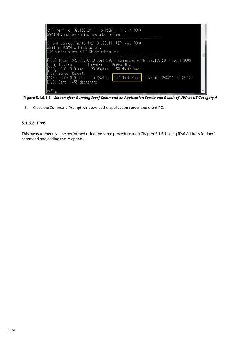
Figure 5.1.6.1-3 Screen after Running Iperf Command on Application Server and Result of UDP at UE Category 4
6. Close the Command Prompt windows at the application server and client PCs.
5.1.6.2. IPv6 This measurement can be performed using the same procedure as in Chapter 5.1.6.1 using IPv6 Address for iperf command and adding the -V option.
274
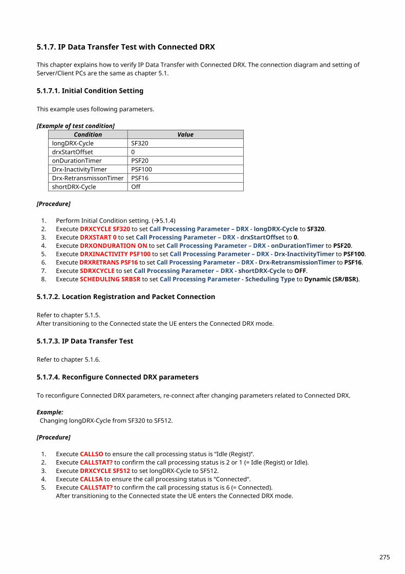
IP Data Transfer Test with Connected DRX 5.1.7. This chapter explains how to verify IP Data Transfer with Connected DRX. The connection diagram and setting of Server/Client PCs are the same as chapter 5.1. 5.1.7.1. Initial Condition Setting This example uses following parameters. [Example of test condition]
Condition Value longDRX-Cycle SF320 drxStartOffset 0 onDurationTimer PSF20 Drx-InactivityTimer PSF100 Drx-RetransmissonTimer PSF16 shortDRX-Cycle Off
[Procedure]
1. Perform Initial Condition setting. (5.1.4) 2. Execute DRXCYCLE SF320 to set Call Processing Parameter – DRX - longDRX-Cycle to SF320. 3. Execute DRXSTART 0 to set Call Processing Parameter – DRX - drxStartOffset to 0. 4. Execute DRXONDURATION ON to set Call Processing Parameter – DRX - onDurationTimer to PSF20. 5. Execute DRXINACTIVITY PSF100 to set Call Processing Parameter – DRX - Drx-InactivityTimer to PSF100. 6. Execute DRXRETRANS PSF16 to set Call Processing Parameter – DRX - Drx-RetransmissionTimer to PSF16. 7. Execute SDRXCYCLE to set Call Processing Parameter – DRX - shortDRX-Cycle to OFF. 8. Execute SCHEDULING SRBSR to set Call Processing Parameter - Scheduling Type to Dynamic (SR/BSR).
5.1.7.2. Location Registration and Packet Connection
Refer to chapter 5.1.5. After transitioning to the Connected state the UE enters the Connected DRX mode. 5.1.7.3. IP Data Transfer Test
Refer to chapter 5.1.6. 5.1.7.4. Reconfigure Connected DRX parameters To reconfigure Connected DRX parameters, re-connect after changing parameters related to Connected DRX. Example: Changing longDRX-Cycle from SF320 to SF512.
[Procedure]
1. Execute CALLSO to ensure the call processing status is “Idle (Regist)“. 2. Execute CALLSTAT? to confirm the call processing status is 2 or 1 (= Idle (Regist) or Idle). 3. Execute DRXCYCLE SF512 to set longDRX-Cycle to SF512. 4. Execute CALLSA to ensure the call processing status is “Connected“. 5. Execute CALLSTAT? to confirm the call processing status is 6 (= Connected).
After transitioning to the Connected state the UE enters the Connected DRX mode.
275
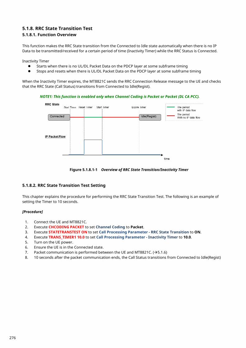
RRC State Transition Test 5.1.8.5.1.8.1. Function Overview This function makes the RRC State transition from the Connected to Idle state automatically when there is no IP Data to be transmitted/received for a certain period of time (Inactivity Timer) while the RRC Status is Connected. Inactivity Timer Starts when there is no UL/DL Packet Data on the PDCP layer at some subframe timing Stops and resets when there is UL/DL Packet Data on the PDCP layer at some subframe timing
When the Inactivity Timer expires, the MT8821C sends the RRC Connection Release message to the UE and checks that the RRC State (Call Status) transitions from Connected to Idle(Regist).
NOTE1: This function is enabled only when Channel Coding is Packet or Packet (DL CA PCC).
Figure 5.1.8.1-1 Overview of RRC State Transition/Inactivity Timer
5.1.8.2. RRC State Transition Test Setting This chapter explains the procedure for performing the RRC State Transition Test. The following is an example of setting the Timer to 10 seconds. [Procedure]
1. Connect the UE and MT8821C. 2. Execute CHCODING PACKET to set Channel Coding to Packet. 3. Execute STATETRANSTEST ON to set Call Processing Parameter - RRC State Transition to ON. 4. Execute TRANS_TIMER1 10.0 to set Call Processing Parameter - Inactivity Timer to 10.0. 5. Turn on the UE power. 6. Ensure the UE is in the Connected state. 7. Packet communication is performed between the UE and MT8821C. (5.1.6) 8. 10 seconds after the packet communication ends, the Call Status transitions from Connected to Idle(Regist)
276
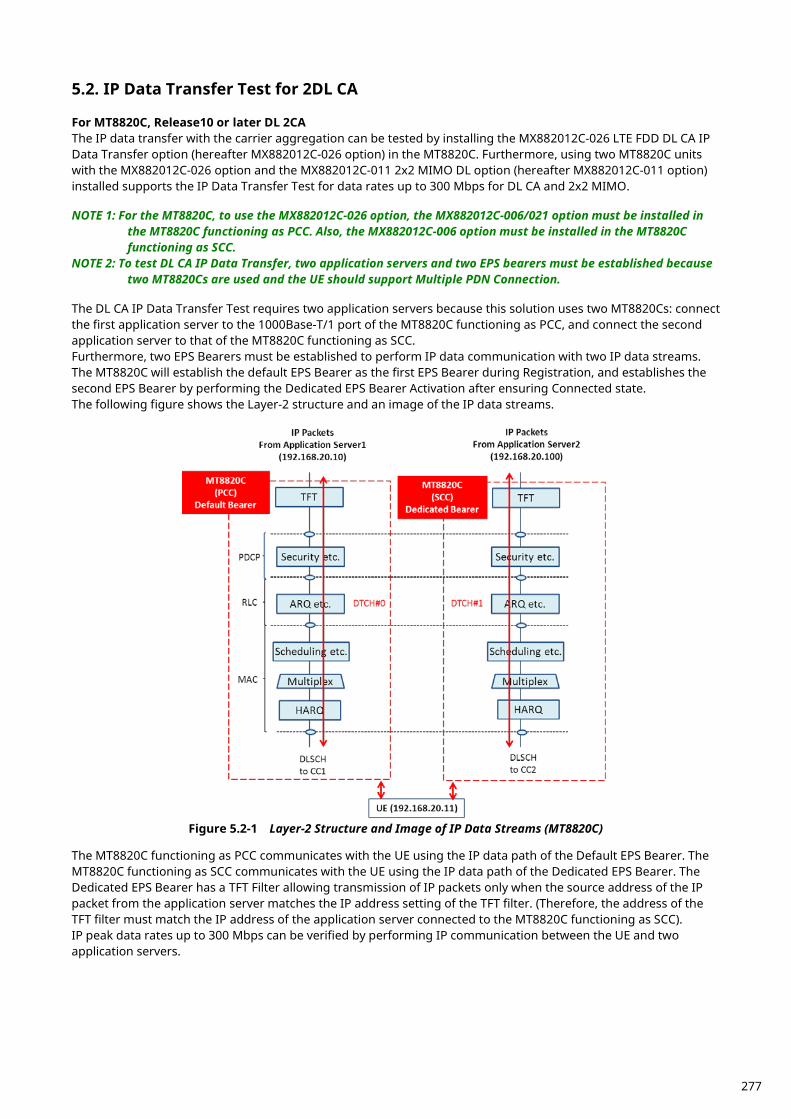
IP Data Transfer Test for 2DL CA 5.2. For MT8820C, Release10 or later DL 2CA The IP data transfer with the carrier aggregation can be tested by installing the MX882012C-026 LTE FDD DL CA IP Data Transfer option (hereafter MX882012C-026 option) in the MT8820C. Furthermore, using two MT8820C units with the MX882012C-026 option and the MX882012C-011 2x2 MIMO DL option (hereafter MX882012C-011 option) installed supports the IP Data Transfer Test for data rates up to 300 Mbps for DL CA and 2x2 MIMO. NOTE 1: For the MT8820C, to use the MX882012C-026 option, the MX882012C-006/021 option must be installed in
the MT8820C functioning as PCC. Also, the MX882012C-006 option must be installed in the MT8820C functioning as SCC.
NOTE 2: To test DL CA IP Data Transfer, two application servers and two EPS bearers must be established because two MT8820Cs are used and the UE should support Multiple PDN Connection.
The DL CA IP Data Transfer Test requires two application servers because this solution uses two MT8820Cs: connect the first application server to the 1000Base-T/1 port of the MT8820C functioning as PCC, and connect the second application server to that of the MT8820C functioning as SCC. Furthermore, two EPS Bearers must be established to perform IP data communication with two IP data streams. The MT8820C will establish the default EPS Bearer as the first EPS Bearer during Registration, and establishes the second EPS Bearer by performing the Dedicated EPS Bearer Activation after ensuring Connected state. The following figure shows the Layer-2 structure and an image of the IP data streams.
Figure 5.2-1 Layer-2 Structure and Image of IP Data Streams (MT8820C)
The MT8820C functioning as PCC communicates with the UE using the IP data path of the Default EPS Bearer. The MT8820C functioning as SCC communicates with the UE using the IP data path of the Dedicated EPS Bearer. The Dedicated EPS Bearer has a TFT Filter allowing transmission of IP packets only when the source address of the IP packet from the application server matches the IP address setting of the TFT filter. (Therefore, the address of the TFT filter must match the IP address of the application server connected to the MT8820C functioning as SCC). IP peak data rates up to 300 Mbps can be verified by performing IP communication between the UE and two application servers.
277
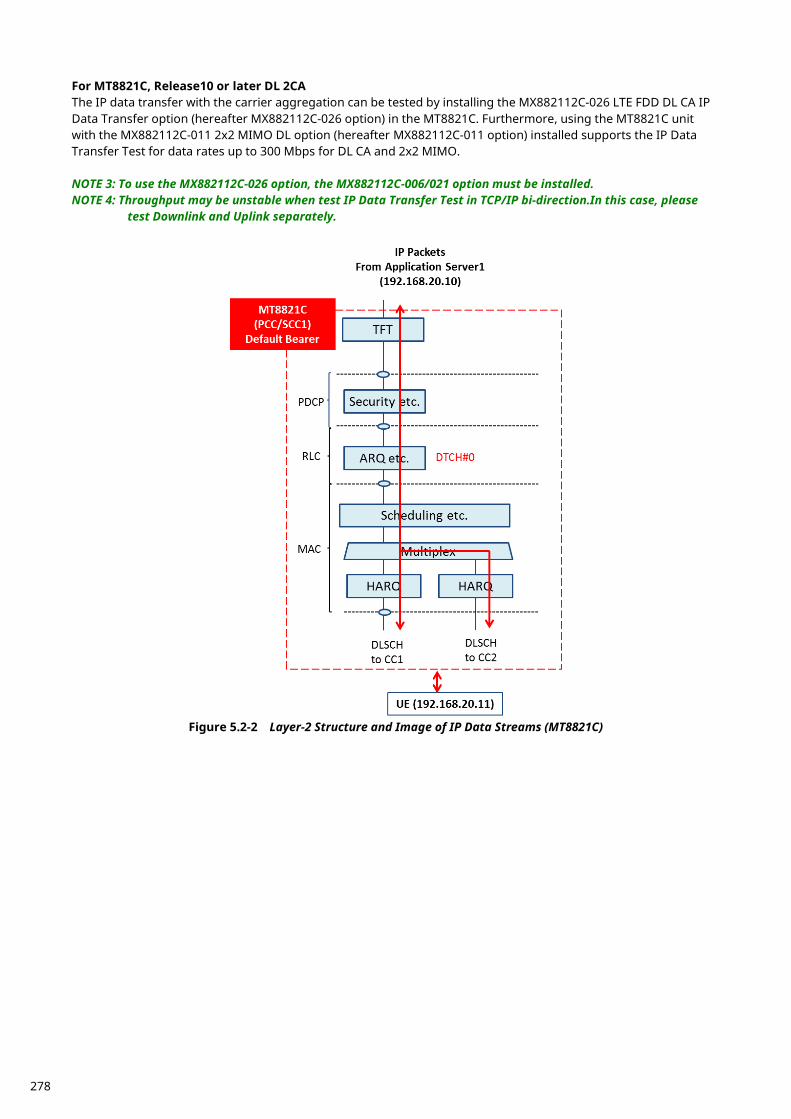
For MT8821C, Release10 or later DL 2CA The IP data transfer with the carrier aggregation can be tested by installing the MX882112C-026 LTE FDD DL CA IP Data Transfer option (hereafter MX882112C-026 option) in the MT8821C. Furthermore, using the MT8821C unit with the MX882112C-011 2x2 MIMO DL option (hereafter MX882112C-011 option) installed supports the IP Data Transfer Test for data rates up to 300 Mbps for DL CA and 2x2 MIMO. NOTE 3: To use the MX882112C-026 option, the MX882112C-006/021 option must be installed. NOTE 4: Throughput may be unstable when test IP Data Transfer Test in TCP/IP bi-direction.In this case, please
test Downlink and Uplink separately.
Figure 5.2-2 Layer-2 Structure and Image of IP Data Streams (MT8821C)
278
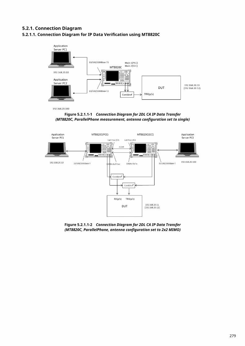
Connection Diagram 5.2.1.5.2.1.1. Connection Diagram for IP Data Verification using MT8820C
Figure 5.2.1.1-1 Connection Diagram for 2DL CA IP Data Transfer
(MT8820C, ParallelPhone measurement, antenna configuration set to single)
Figure 5.2.1.1-2 Connection Diagram for 2DL CA IP Data Transfer (MT8820C, ParallelPhone, antenna configuration set to 2x2 MIMO)
r
r
r
279
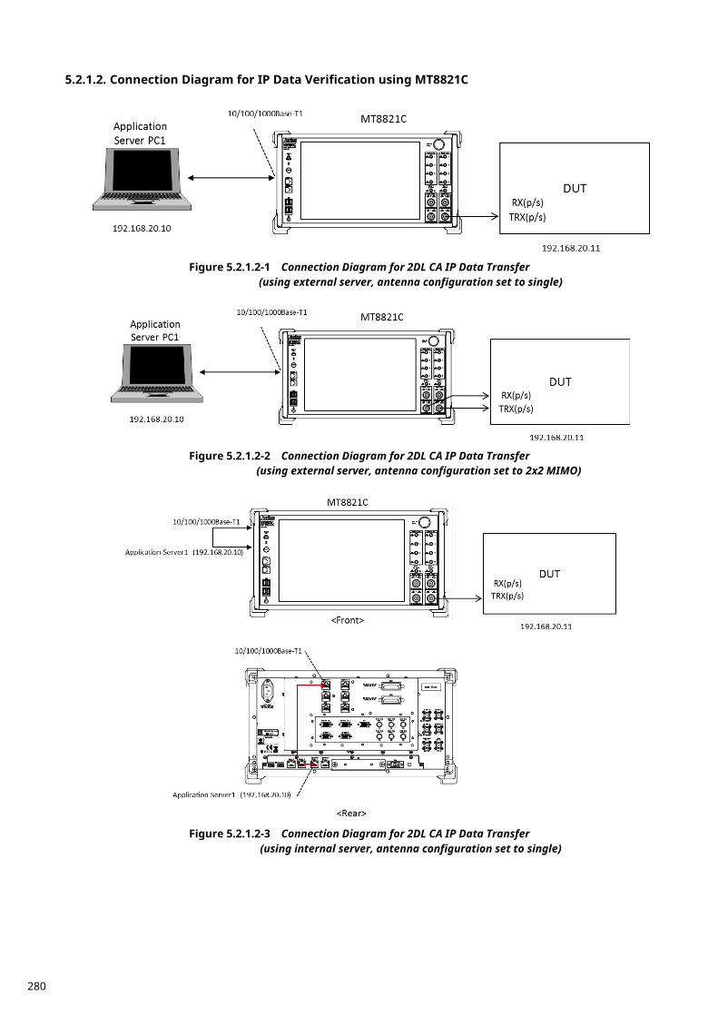
5.2.1.2. Connection Diagram for IP Data Verification using MT8821C
Figure 5.2.1.2-1 Connection Diagram for 2DL CA IP Data Transfer
(using external server, antenna configuration set to single)
Figure 5.2.1.2-2 Connection Diagram for 2DL CA IP Data Transfer
(using external server, antenna configuration set to 2x2 MIMO)
Figure 5.2.1.2-3 Connection Diagram for 2DL CA IP Data Transfer
(using internal server, antenna configuration set to single)
280
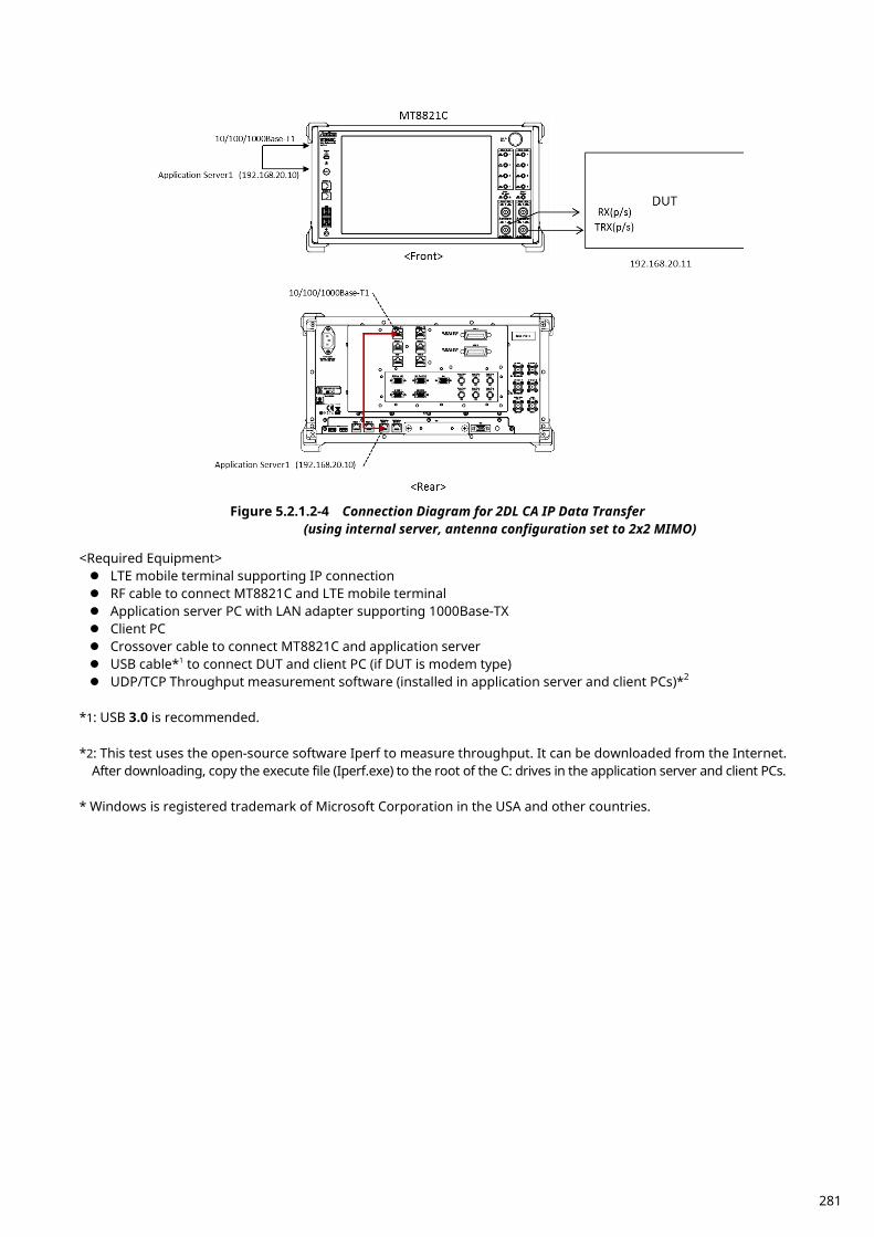
Figure 5.2.1.2-4 Connection Diagram for 2DL CA IP Data Transfer
(using internal server, antenna configuration set to 2x2 MIMO)
<Required Equipment> LTE mobile terminal supporting IP connection RF cable to connect MT8821C and LTE mobile terminal Application server PC with LAN adapter supporting 1000Base-TX Client PC Crossover cable to connect MT8821C and application server USB cable*1 to connect DUT and client PC (if DUT is modem type) UDP/TCP Throughput measurement software (installed in application server and client PCs)*2
*1: USB 3.0 is recommended. *2: This test uses the open-source software Iperf to measure throughput. It can be downloaded from the Internet.
After downloading, copy the execute file (Iperf.exe) to the root of the C: drives in the application server and client PCs. * Windows is registered trademark of Microsoft Corporation in the USA and other countries.
281
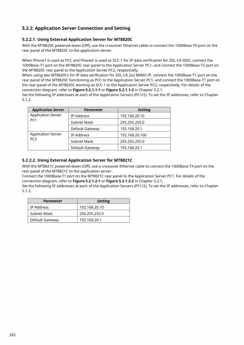
Application Server Connection and Setting 5.2.2. 5.2.2.1. Using External Application Server for MT8820C With the MT8820C powered-down (Off), use the crossover Ethernet cable to connect the 1000Base-TX port on the rear panel of the MT8820C to the application server. When Phone1 is used as PCC and Phone2 is used as SCC-1 for IP data verification for 2DL CA SISO, connect the 1000Base-T1 port on the MT8820C rear panel to the Application Server PC1, and connect the 1000Base-T2 port on the MT8820C rear panel to the Application Server PC2, respectively. When using two MT8820Cs for IP data verification for 2DL CA 2x2 MIMO IP, connect the 1000Base-T1 port on the rear panel of the MT8820C functioning as PCC to the Application Server PC1, and connect the 1000Base-T1 port on the rear panel of the MT8820C working as SCC-1 to the Application Server PC2, respectively. For details of the connection diagram, refer to Figure 5.2.1.1-1 or Figure 5.2.1.1-2 in Chapter 5.2.1. Set the following IP addresses at each of the Application Servers (PC1/2). To set the IP addresses, refer to Chapter 5.1.2.
Application Server Parameter Setting Application Server PC1
IP Address 192.168.20.10
Subnet Mask 255.255.255.0
Default Gateway 192.168.20.1 Application Server PC2
IP Address 192.168.20.100
Subnet Mask 255.255.255.0
Default Gateway 192.168.20.1 5.2.2.2. Using External Application Server for MT8821C With the MT8821C powered-down (Off), use a crossover Ethernet cable to connect the 1000Base-TX port on the rear panel of the MT8821C to the application server. Connect the 1000Base-T1 port on the MT8821C rear panel to the Application Server PC1. For details of the connection diagram, refer to Figure 5.2.1.2-1 or Figure 5.2.1.2-2 in Chapter 5.2.1. Set the following IP addresses at each of the Application Servers (PC1/2). To set the IP addresses, refer to Chapter 5.1.2.
Parameter Setting IP Address 192.168.20.10
Subnet Mask 255.255.255.0
Default Gateway 192.168.20.1
282
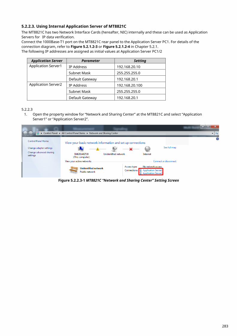
5.2.2.3. Using Internal Application Server of MT8821C The MT8821C has two Network Interface Cards (hereafter, NIC) internally and these can be used as Application Servers for IP data verification. Connect the 1000Base-T1 port on the MT8821C rear panel to the Application Server PC1. For details of the connection diagram, refer to Figure 5.2.1.2-3 or Figure 5.2.1.2-4 in Chapter 5.2.1. The following IP addresses are assigned as initial values at Application Server PC1/2
Application Server Parameter Setting Application Server1 IP Address 192.168.20.10
Subnet Mask 255.255.255.0
Default Gateway 192.168.20.1 Application Server2 IP Address 192.168.20.100
Subnet Mask 255.255.255.0
Default Gateway 192.168.20.1 5.2.2.3
1. Open the property window for “Network and Sharing Center” at the MT8821C and select “Application Server1” or “Application Server2”.
Figure 5.2.2.3-1 MT8821C “Network and Sharing Center” Setting Screen
283
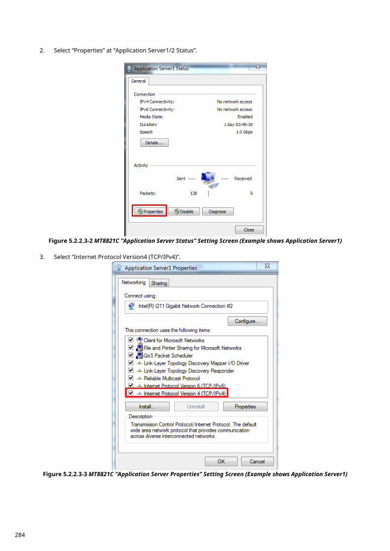
2. Select “Properties” at “Application Server1/2 Status”.
Figure 5.2.2.3-2 MT8821C “Application Server Status” Setting Screen (Example shows Application Server1)
3. Select “Internet Protocol Version4 (TCP/IPv4)”.
Figure 5.2.2.3-3 MT8821C “Application Server Properties” Setting Screen (Example shows Application Server1)
284
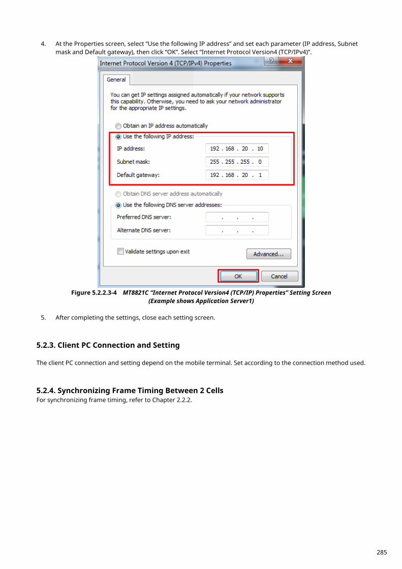
4. At the Properties screen, select “Use the following IP address” and set each parameter (IP address, Subnet mask and Default gateway), then click “OK”. Select “Internet Protocol Version4 (TCP/IPv4)”.
Figure 5.2.2.3-4 MT8821C “Internet Protocol Version4 (TCP/IP) Properties” Setting Screen
(Example shows Application Server1)
5. After completing the settings, close each setting screen.
Client PC Connection and Setting 5.2.3. The client PC connection and setting depend on the mobile terminal. Set according to the connection method used.
Synchronizing Frame Timing Between 2 Cells 5.2.4.For synchronizing frame timing, refer to Chapter 2.2.2.
285
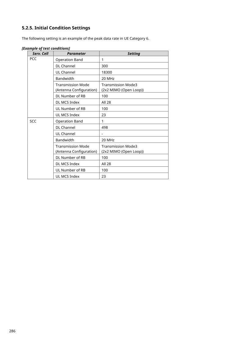
Initial Condition Settings 5.2.5. The following setting is an example of the peak data rate in UE Category 6. [Example of test conditions]
Serv. Cell Parameter Setting PCC Operation Band 1
DL Channel 300
UL Channel 18300
Bandwidth 20 MHz
Transmission Mode (Antenna Configuration)
Transmission Mode3 (2x2 MIMO (Open Loop))
DL Number of RB 100
DL MCS Index All 28
UL Number of RB 100
UL MCS Index 23
SCC Operation Band 1
DL Channel 498
UL Channel -
Bandwidth 20 MHz
Transmission Mode (Antenna Configuration)
Transmission Mode3 (2x2 MIMO (Open Loop))
DL Number of RB 100
DL MCS Index All 28
UL Number of RB 100
UL MCS Index 23
286
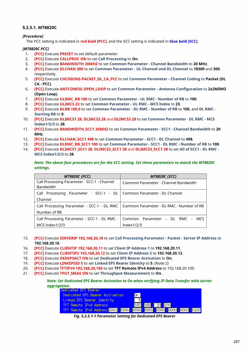
5.2.5.1. MT8820C [Procedure] The PCC setting is indicated in red bold [PCC], and the SCC setting is indicated in blue bold [SCC]. [MT8820C PCC]
1. [PCC] Execute PRESET to set default parameter. 2. [PCC] Execute CALLPROC ON to set Call Processing to On. 3. [PCC] Execute BANDWIDTH 20MHZ to set Common Parameter - Channel Bandwidth to 20 MHz. 4. [PCC] Execute DLCHAN 300 to set Common Parameter - UL Channel and DL Channel to 18300 and 300,
respectively. 5. [PCC] Execute CHCODING PACKET_DL_CA_PCC to set Common Parameter - Channel Coding to Packet (DL
CA - PCC). 6. [PCC] Execute ANTCONFIG OPEN_LOOP to set Common Parameter - Antenna Configuration to 2x2MIMO
(Open Loop). 7. [PCC] Execute ULRMC_RB 100 to set Common Parameter - UL RMC - Number of RB to 100. 8. [PCC] Execute ULIMCS 23 to set Common Parameter - UL RMC - MCS Index to 23. 9. [PCC] Execute DLRB 100,0 to set Common Parameter - DL RMC - Number of RB to 100, and DL RMC -
Starting RB to 0. 10. [PCC] Execute DLIMCS1 28, DLIMCS2 28 and DLIMCS3 28 to set Common Parameter - DL RMC - MCS
Index1/2/3 to 28. 11. [PCC] Execute BANDWIDTH_SCC1 20MHZ to set Common Parameter - SCC1 - Channel Bandwidth to 20
MHz. 12. [PCC] Execute DLCHAN_SCC1 498 to set Common Parameter - SCC1 - DL Channel to 498. 13. [PCC] Execute DLRMC_RB_SCC1 100 to set Common Parameter - SCC1 - DL RMC - Number of RB to 100. 14. [PCC] Execute DLIMCS1_SCC1 28, DLIMCS2_SCC1 28 and DLIMCS3_SCC1 28 to set All of SCC1 - DL RMC -
MCS Index1/2/3 to 28. Note: The above four procedures are for the SCC setting. Set these parameters to match the MT8820C settings.
MT8820C (PCC) MT8820C (SCC)
Call Processing Parameter - SCC-1 - Channel Bandwidth
Common Parameter - Channel Bandwidth
Call Processing Parameter - SCC-1 - DL
Channel
Common Parameter - DL Channel
Call Processing Parameter - SCC-1 - DL RMC
Number of RB
Common Parameter - DL RMC - Number of RB
Call Processing Parameter - SCC-1 - DL RMC -
MCS Index1/2/3
Common Parameter - DL RMC - MCS
Index1/2/3 15. [PCC] Execute SERVERIP 192,168,20,10 to set Call Processing Parameter - Packet - Server IP Address to
192.168.20.10. 16. [PCC] Execute CLIENTIP 192,168,20,11 to set Client IP Address 1 to 192.168.20.11. 17. [PCC] Execute CLIENTIP2 192,168,20,12 to set Client IP Address 2 to 192.168.20.12. 18. [PCC] Execute DEDEPSACT ON to set Dedicated EPS Bearer Activation to On. 19. [PCC] Execute LINKEPSID 5 to set Linked EPS Bearer Identity to 5. (Note 2) 20. [PCC] Execute TFTIPV4 192,168,20,100 to set TFT Remote IPv4 Address to 192.168.20.100. 21. [PCC] Execute TPUT_MEAS ON to set Throughput Measurement to On.
Note: Set Dedicated EPS Bearer Activation to On when verifying IP Data Transfer with carrier aggregation.
Fig. 5.2.5.1-1 Parameter Setting for Dedicated EPS Bearer
287
[MT8820C SCC] 22. [SCC] Execute PRESET to set default parameters. 23. [SCC] Execute CALLPROC OFF to set Call Processing to Off. 24. [SCC] Execute BANDWIDTH 20MHZ to set Channel Bandwidth to 20 MHz. 25. [SCC] Execute DLCHAN 498 to DL Channel to 498. 26. [SCC] Execute CHCODING PACKET_DL_CA_SCC to set Channel Coding to Packet (DL CA - SCC). 27. [SCC] Execute ANTCONFIG OPEN_LOOP to set Antenna Configuration to 2x2MIMO (Open Loop). 28. [SCC] Execute DLRB 100,0 to set DL RMC - Number of RB to 100, and DL RMC - Starting RB to 0. 29. [SCC] Execute DLIMCS1 28, DLIMCS2 28 and DLIMCS3 28 to set All of DL RMC - MCS Index(x) to 28. 30. [SCC] Execute BANDWIDTH_PCC 20MHZ to set PCC - Channel Bandwidth to 20 MHz. 31. [SCC] Execute ULCHAN_PCC 18300 to set PCC - UL Channel to 18300. 32. [SCC] Execute ULRMCRB_PCC 100 to set PCC - UL RMC - Number of RB to 100. 33. [SCC] Execute ULRB_START_PCC 0 to set PCC - UL RMC - Starting RB to 0. 34. [SCC] Execute ULIMCS_PCC 23 to set PCC - MCS Index to 23.
Note: The above five procedures are necessary to receive the uplink signal at the MT8820C SCC. Set the same parameters as the MT8820C functioning as PCC.
MT8820C (PCC) MT8820C (SCC) Common Parameter - Channel Bandwidth Call Processing Parameter - PCC - Channel
Bandwidth
Common Parameter - UL Channel Call Processing Parameter - PCC - UL Channel
Common Parameter - UL RMC - Number of RB Call Processing Parameter - PCC - UL RMC
Number of RB
Common Parameter - UL RMC - Starting RB Call Processing Parameter - PCC - UL RMC
Starting RB
Common Parameter - UL RMC - MCS Index Call Processing Parameter - PCC - UL RMC
MCS Index 35. [SCC] Execute SERVERIP 192,168,20,10 to set Server IP Address to 192.168.20.10. 36. [SCC] Execute CLIENTIP 192,168,20,11 to set Client IP Address to 192.168.20.11. 37. [SCC] Execute CLIENTIP2 192,168,20,12 to set Client IP Address 2 to 192.168.20.12. 38. [SCC] Execute DEDEPSACT ON to set Dedicated EPS Bearer Activation to On. 39. [SCC] Execute LINKEPSID 5 to set Linked EPS Bearer Identity to 5. (Note 2) 40. [SCC] Execute TFTIPV4 192.168.20.100 to set TFT Remote IPv4 Address to 192.168.20.100. 41. [SCC] Execute CALLSO to reset the internal configuration of the MT8820C SCC.
Note 1: Execute this procedure to ensure IP Data communication on the MT8820C SCC.
Note 2: Some UEs may request establishment of the second Default EPS Bearer by conveying a PDN Connectivity Request message after checking the Connected state. To verify IP data communication with this UE and communicate to the second EPS Bearer, execute following procedure instead of step19 and step 38. 19. [PCC] Execute LINKEPSID 6 to set Linked EPS Bearer Identity to 6. 38. [SCC] Execute LINKEPSID 6 to set Linked EPS Bearer Identity to 6. The Dedicated EPS Bearer will be linked to the second Default EPS Bearer by these settings. The SCC using the dedicated EPS Bearer as the IP data path will communicate with the second Default EPS Bearer's IP address (Call Processing Parameter - Client IP Address2).
[Example of IP Data Path when Linked EPS Bearer Identity Set to 6] The SCC can communicate with the second EPS Bearer’s IP address (Call Processing Parameter - Client IP Address2).
288
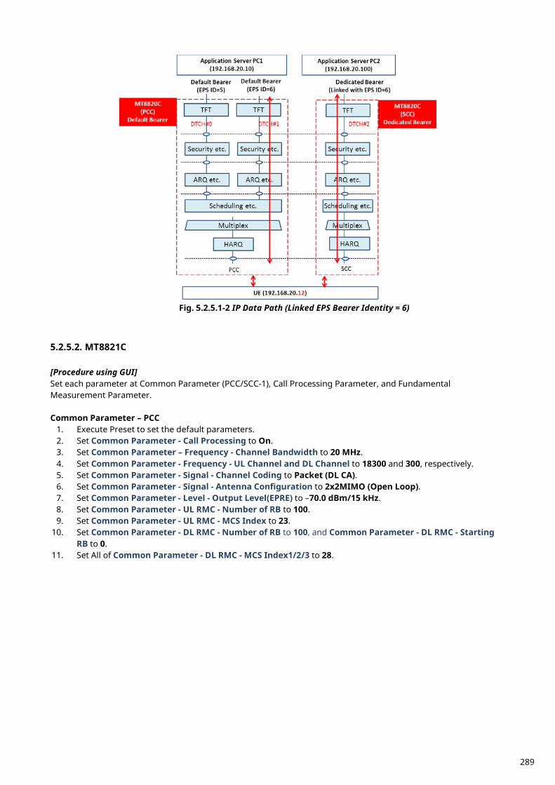
Fig. 5.2.5.1-2 IP Data Path (Linked EPS Bearer Identity = 6)
5.2.5.2. MT8821C [Procedure using GUI] Set each parameter at Common Parameter (PCC/SCC-1), Call Processing Parameter, and Fundamental Measurement Parameter. Common Parameter – PCC
1. Execute Preset to set the default parameters. 2. Set Common Parameter - Call Processing to On. 3. Set Common Parameter – Frequency - Channel Bandwidth to 20 MHz. 4. Set Common Parameter - Frequency - UL Channel and DL Channel to 18300 and 300, respectively. 5. Set Common Parameter - Signal - Channel Coding to Packet (DL CA). 6. Set Common Parameter - Signal - Antenna Configuration to 2x2MIMO (Open Loop). 7. Set Common Parameter - Level - Output Level(EPRE) to –70.0 dBm/15 kHz. 8. Set Common Parameter - UL RMC - Number of RB to 100. 9. Set Common Parameter - UL RMC - MCS Index to 23.
10. Set Common Parameter - DL RMC - Number of RB to 100, and Common Parameter - DL RMC - Starting RB to 0.
11. Set All of Common Parameter - DL RMC - MCS Index1/2/3 to 28.
289

Call Processing Parameter
1. Set Call Processing Parameter - Carrier Aggregation - Number of DL SCC to 1. 2. Set Call Processing Parameter - Packet - Server IP Address to 192.168.20.10. 3. Set Call Processing Parameter - Packet - Client IP Address 1 to 192.168.20.11. 4. Set Call Processing Parameter - Packet - Client IP Address 2 to 192.168.20.12. 5. Set Call Processing Parameter - Packet - TFT Remote IPv4 Address to 192.168.20.100.
Common Parameter - SCC-1
1. Set Common Parameter - SCC1 - Channel Bandwidth to 20 MHz. 2. Set Common Parameter - SCC1 - DL Channel to 498. 3. Set Common Parameter - SCC-1 - Output Level(EPRE) to –70.0 dBm/15 kHz. 4. Set Common Parameter - SCC1 - DL RMC - Number of RB to 100, and Common Parameter - SCC1 - DL
RMC - Starting RB to 0.
290
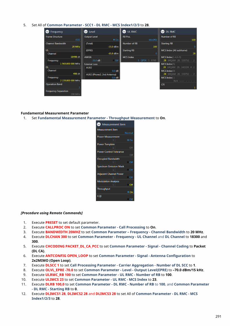
5. Set All of Common Parameter - SCC1 - DL RMC - MCS Index1/2/3 to 28.
Fundamental Measurement Parameter
1. Set Fundamental Measurement Parameter - Throughput Measurement to On.
[Procedure using Remote Commands]
1. Execute PRESET to set default parameter. 2. Execute CALLPROC ON to set Common Parameter - Call Processing to On. 3. Execute BANDWIDTH 20MHZ to set Common Parameter – Frequency - Channel Bandwidth to 20 MHz. 4. Execute DLCHAN 300 to set Common Parameter - Frequency - UL Channel and DL Channel to 18300 and
300. 5. Execute CHCODING PACKET_DL_CA_PCC to set Common Parameter - Signal - Channel Coding to Packet
(DL CA). 6. Execute ANTCONFIG OPEN_LOOP to set Common Parameter - Signal - Antenna Configuration to
2x2MIMO (Open Loop). 7. Execute DLSCC 1 to set Call Processing Parameter - Carrier Aggregation - Number of DL SCC to 1. 8. Execute OLVL_EPRE -70.0 to set Common Parameter - Level - Output Level(EPRE) to –70.0 dBm/15 kHz. 9. Execute ULRMC_RB 100 to set Common Parameter - UL RMC - Number of RB to 100.
10. Execute ULIMCS 23 to set Common Parameter - UL RMC - MCS Index to 23. 11. Execute DLRB 100,0 to set Common Parameter - DL RMC - Number of RB to 100, and Common Parameter
- DL RMC - Starting RB to 0. 12. Execute DLIMCS1 28, DLIMCS2 28 and DLIMCS3 28 to set All of Common Parameter - DL RMC - MCS
Index1/2/3 to 28.
291
13. Execute BANDWIDTH_SCC1 20MHZ to set Common Parameter - SCC1 - Channel Bandwidth to 20 MHz. 14. Execute DLCHAN_SCC1 498 to set Common Parameter - SCC1 - DL Channel to 498. 15. Execute OLVL_EPRE_SCC1 -70.0 to set Common Parameter - SCC-1 - Output Level(EPRE) to –70.0
dBm/15kHz. 16. Execute DLRB_SCC1 100,0 to set Common Parameter - SCC1 - DL RMC - Number of RB to 100, and
Common Parameter - SCC1 - DL RMC - Starting RB to 0. 17. Execute DLIMCS1_SCC1 28, DLIMCS2_SCC1 28 and DLIMCS3_SCC1 28 to set All of Common Parameter -
SCC1 - DL RMC - MCS Index1/2/3 to 28. 18. Execute SERVERIP 192,168,20,10 to set Call Processing Parameter - Packet - Server IP Address to
192.168.20.10. 19. Execute CLIENTIP 192,168,20,11 to set Call Processing Parameter - Packet - Client IP Address 1 to
192.168.20.11. 20. Execute CLIENTIP2 192,168,20,12 to set Call Processing Parameter - Packet - Client IP Address 2 to
192.168.20.12. 21. Execute TFTIPV4 192,168,20,100 to set Call Processing Parameter - Packet - TFT Remote IPv4 Address to
192.168.20.100. 22. Execute TPUT_MEAS ON to set Fundamental Measurement Parameter - Throughput Measurement to
On.
Location Registration and Packet Connection 5.2.6.5.2.6.1. MT8820
1. [SCC] Execute LVL OFF to set SCell output power to off. 2. [PCC] Execute CALLSO to clear call processing. 3. [PCC] Execute CALLSTAT? to confirm the call processing status is 1 (= Idle). 4. Turn on the UE power. 5. [PCC] Execute CALLSTAT? to confirm the call processing status is 6 (= Connected).
Repeat Polling query response when the checked status is not 6 (= Connected). 6. [SCC] Execute LVL ON to set SCell output power to On. 7. [PCC] Execute TPUT_SAMPLE 2000 to set the number of Throughput measurement samples to 2000. 8. [PCC] Execute SWP to perform the Throughput measurement. 9. [PCC] Execute TPUT? PER to read the Throughput measurement result (%).
If an error occurs, the reception state must to be optimized by changing the RMC setting by referring to Chapter 5.2.5.
5.2.6.2. MT8821
1. Execute CALLSO to clear call processing. 2. Execute CALLSTAT? to confirm the call processing status is 1 (= Idle). 3. Turn on the UE power. 4. Execute CALLSTAT? to confirm the call processing status is 6 (= Connected).
Repeat Polling query response when the checked status is not 6 (= Connected). 5. Execute TPUT_SAMPLE 2000 to set the number of Throughput measurement samples to 2000. 6. Execute SWP to perform the Throughput measurement. 7. Execute TPUT? PER to read the Throughput measurement result (%).
If an error occurs, the DL transmission condition must be optimized by changing the output level or DL RMC setting of each CC by referring to Chapter 5.2.5.
292
TCP/UDP Throughput 5.2.7.5.2.7.1. MT8820C This chapter explains TCP/UDP throughput measurement using the Iperf software for downlink throughput tests. Uplink throughput measurement is supported by switching the application server and client PCs.
1. Open two Command Prompt windows on the Client PC and execute [cd c:¥] to change to the directory containing Iperf.exe. (If the DUT is a smartphone, open the iperf application.)
2. Run the following commands to put the client PC into the wait status. TCP: [iperf -s -i 2 -w 2M -p 50000] UDP: [iperf -s -u -i 2 -w 2M -p 50000]
(If the DUT is smartphone, open the iperf application.) TCP: [-s -i 2 -w 2M -p 50000] UDP: [-s -u -i 2 -w 2M -p 50000]
3. Open the Command Prompt window on Application Server 1/2 and execute [cd c:¥] to change to the directory containing Iperf.exe
[Case1: Linked EPS Bearer Identity = 5, Client IP Address = 192.168.20.11] 4. Run the following commands to send data from Application Server 1 and 2.
TCP: [iperf -c 192.168.20.11 -w 2M -t 100000 -i 1 -p 50000] UDP: [iperf -c 192.168.20.11 -b 150M -w 2M -t 100000 -i 1 -p 50000]
5. The IP data throughput is displayed at the iperf application on the client server.
[Case2: Linked EPS Bearer Identity = 6, Client IPAddress2 = 192.168.20.12]
4. Run the following commands to send data from Application Server 1 and 2.
TCP: [iperf -c 192.168.20.12 -w 2M -t 100000 -i 1 -p 50000] UDP: [iperf -c 192.168.20.12 -b 150M -w 2M -t 100000 -i 1 -p 50000]
5. The IP data throughput is displayed by the iperf application on the client server.
5.2.7.2. MT8821C This chapter explains TCP/UDP throughput measurement using the Iperf software for downlink throughput tests. Uplink throughput measurement is supported by switching the application server and client PCs.
1. Open a Command Prompt windows on the Client PC and execute [cd c:¥] to change to the directory containing Iperf.exe. (If the DUT is a smartphone, open the iperf application)
2. Run the following commands to put the client PC into the wait status. TCP: [iperf -s -i 2 -w 2M -p 50000] UDP: [iperf -s -u -i 2 -w 2M -p 50000]
(If the DUT is a smartphone, open the iperf application) TCP: [-s -i 2 -w 2M -p 50000] UDP: [-s -u -i 2 -w 2M -p 50000]
3. Open the Command Prompt window on Application Server 1 and execute [cd c:¥] to change to the directory containing Iperf.exe
4. Run the following commands to send data from Application Server 1.
TCP: [iperf -c 192.168.20.11 -B 192.168.20.10 -w 2M -t 100000 -i 1 -p 50000] UDP: [iperf -c 192.168.20.11 -B 192.168.20.10 -b 300M -w 2M -t 100000 -i 1 -p 50000]
5. The IP data throughput is displayed by the iperf application on the client server. Note: Refer to B.3, adjust the buffer size (“-w” option argument) to match the performance of the Application
Server and the data rate. Change the port number (“-p” option argument) to match the Application Server. The same port number may be used by other applications on the PC.
293
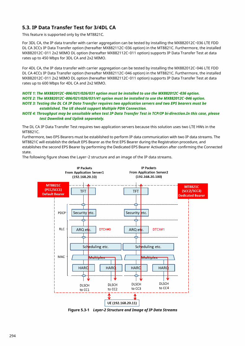
IP Data Transfer Test for 3/4DL CA 5.3.This feature is supported only by the MT8821C. For 3DL CA, the IP data transfer with carrier aggregation can be tested by installing the MX882012C–036 LTE FDD DL CA 3CCs IP Data Transfer option (hereafter MX882112C–036 option) in the MT8821C. Furthermore, the installed MX882012C–011 2x2 MIMO DL option (hereafter MX882112C–011 option) supports IP Data Transfer Test at data rates up to 450 Mbps for 3DL CA and 2x2 MIMO. For 4DL CA, the IP data transfer with carrier aggregation can be tested by installing the MX882012C–046 LTE FDD DL CA 4CCs IP Data Transfer option (hereafter MX882112C–046 option) in the MT8821C. Furthermore, the installed MX882012C–011 2x2 MIMO DL option (hereafter MX882112C–011 option) supports IP Data Transfer Test at data rates up to 600 Mbps for 4DL CA and 2x2 MIMO. NOTE 1: The MX882012C–006/021/026/031 option must be installed to use the MX882012C–036 option. NOTE 2: The MX882012C–006/021/026/031/41 option must be installed to use the MX882012C–046 option. NOTE 3: Testing the DL CA IP Data Transfer requires two application servers and two EPS bearers must be
established. The UE should support Multiple PDN Connection. NOTE 4: Throughput may be unsuitable when test IP Data Transfer Test in TCP/IP bi-direction.In this case, please
test Downlink and Uplink separately. The DL CA IP Data Transfer Test requires two application servers because this solution uses two LTE HWs in the MT8821C. Furthermore, two EPS Bearers must be established to perform IP data communication with two IP data streams. The MT8821C will establish the default EPS Bearer as the first EPS Bearer during the Registration procedure, and establishes the second EPS Bearer by performing the Dedicated EPS Bearer Activation after confirming the Connected state. The following figure shows the Layer–2 structure and an image of the IP data streams.
Figure 5.3-1 Layer-2 Structure and Image of IP Data Streams
294
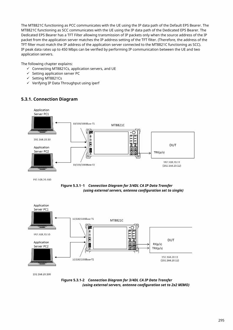
The MT8821C functioning as PCC communicates with the UE using the IP data path of the Default EPS Bearer. The MT8821C functioning as SCC communicates with the UE using the IP data path of the Dedicated EPS Bearer. The Dedicated EPS Bearer has a TFT Filter allowing transmission of IP packets only when the source address of the IP packet from the application server matches the IP address setting of the TFT filter. (Therefore, the address of the TFT filter must match the IP address of the application server connected to the MT8821C functioning as SCC). IP peak data rates up to 450 Mbps can be verified by performing IP communication between the UE and two application servers. The following chapter explains: Connecting MT8821Cs, application servers, and UE Setting application server PC Setting MT8821Cs Verifying IP Data Throughput using iperf
Connection Diagram 5.3.1.
Figure 5.3.1–1 Connection Diagram for 3/4DL CA IP Data Transfer
(using external servers, antenna configuration set to single)
Figure 5.3.1-2 Connection Diagram for 3/4DL CA IP Data Transfer
(using external servers, antenna configuration set to 2x2 MIMO)
295
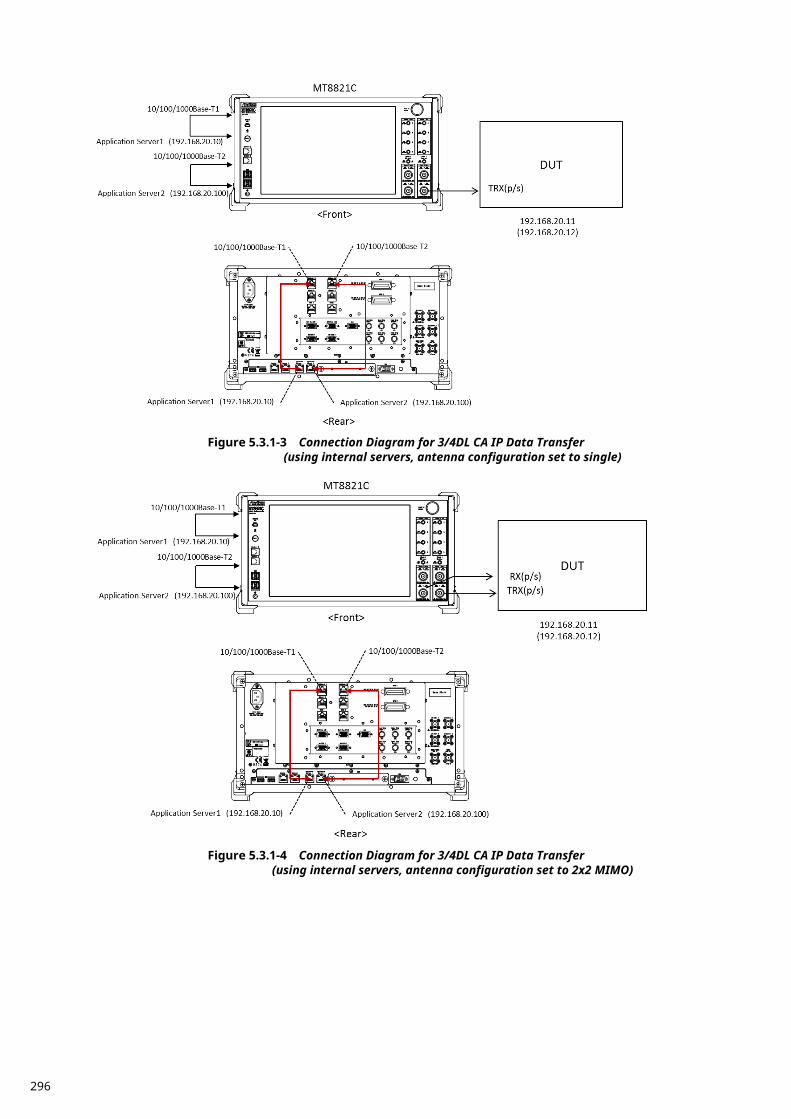
Figure 5.3.1-3 Connection Diagram for 3/4DL CA IP Data Transfer
(using internal servers, antenna configuration set to single)
Figure 5.3.1-4 Connection Diagram for 3/4DL CA IP Data Transfer
(using internal servers, antenna configuration set to 2x2 MIMO)
296
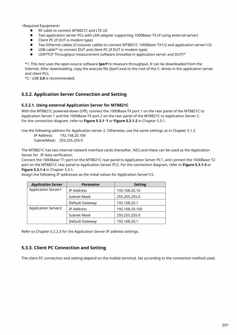
<Required Equipment> RF cable to connect MT8821C and LTE UE Two application server PCs with LAN adapter supporting 1000Base–TX (if using external server) Client PC (if DUT is modem type) Two Ethernet cables (Crossover cables to connect MT8821C 1000Base–TX1/2 and application server1/2) USB cable*2 to connect DUT and client PC (if DUT is modem type) UDP/TCP Throughput measurement software (installed in application server and DUT)*1
*1: This test uses the open-source software Iperf to measure throughput. It can be downloaded from the Internet. After downloading, copy the execute file (Iperf.exe) to the root of the C: drives in the application server and client PCs. *2 : USB 3.0 is recommended.
Application Server Connection and Setting 5.3.2. 5.3.2.1. Using external Application Server for MT8821C With the MT8821C powered-down (Off), connect the 1000Base-TX port 1 on the rear panel of the MT8821C to Application Server 1 and the 1000Base-TX port 2 on the rear panel of the MT8821C to Application Server 2. For the connection diagram, refer to Figure 5.3.1–1 or Figure 5.3.1-2 in Chapter 5.3.1. Use the following address for Application server 2. Otherwise, use the same settings as in Chapter 5.1.2 IP Address: 192.168.20.100 SubnetMask: 255.255.255.0 The MT8821C has two internal network interface cards (hereafter, NIC) and these can be used as the Application Server for IP data verification. Connect the 1000Base–T1 port on the MT8821C rear panel to Application Server PC1, and connect the 1000Base–T2 port on the MT8821C rear panel to Application Server PC2. For the connection diagram, refer to Figure 5.3.1-3 or Figure 5.3.1-4 in Chapter 5.3.1. Assign the following IP addresses as the initial values for Application Server1/2.
Application Server Parameter Setting Application Server1 IP Address 192.168.20.10
Subnet Mask 255.255.255.0
Default Gateway 192.168.20.1 Application Server2 IP Address 192.168.20.100
Subnet Mask 255.255.255.0
Default Gateway 192.168.20.1 Refer to Chapter 5.2.2.3 for the Application Server IP address settings.
Client PC Connection and Setting 5.3.3. The client PC connection and setting depend on the mobile terminal. Set according to the connection method used.
297
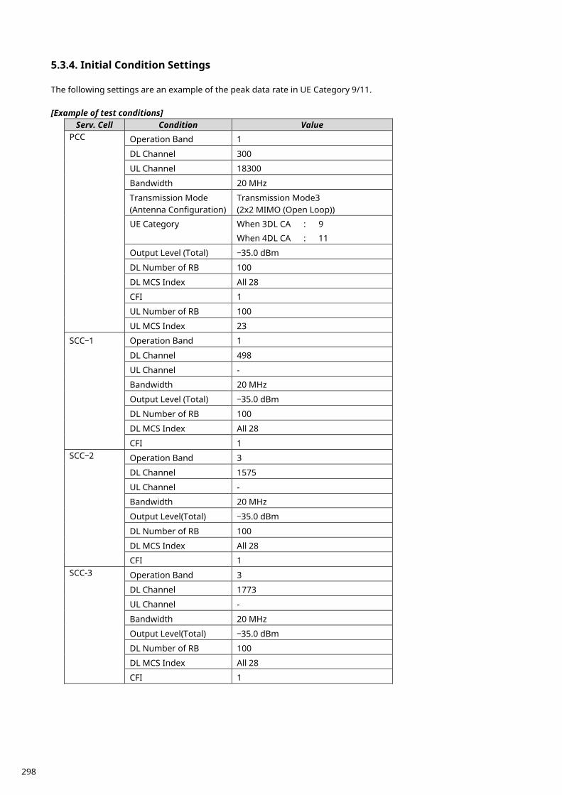
Initial Condition Settings 5.3.4. The following settings are an example of the peak data rate in UE Category 9/11. [Example of test conditions]
Serv. Cell Condition Value PCC Operation Band 1
DL Channel 300
UL Channel 18300
Bandwidth 20 MHz
Transmission Mode (Antenna Configuration)
Transmission Mode3 (2x2 MIMO (Open Loop))
UE Category When 3DL CA : 9
When 4DL CA : 11
Output Level (Total) –35.0 dBm
DL Number of RB 100
DL MCS Index All 28
CFI 1
UL Number of RB 100
UL MCS Index 23
SCC–1 Operation Band 1
DL Channel 498
UL Channel -
Bandwidth 20 MHz
Output Level (Total) –35.0 dBm
DL Number of RB 100
DL MCS Index All 28
CFI 1 SCC–2 Operation Band 3
DL Channel 1575
UL Channel -
Bandwidth 20 MHz
Output Level(Total) –35.0 dBm
DL Number of RB 100
DL MCS Index All 28
CFI 1 SCC-3 Operation Band 3
DL Channel 1773
UL Channel -
Bandwidth 20 MHz
Output Level(Total) –35.0 dBm
DL Number of RB 100
DL MCS Index All 28
CFI 1
298
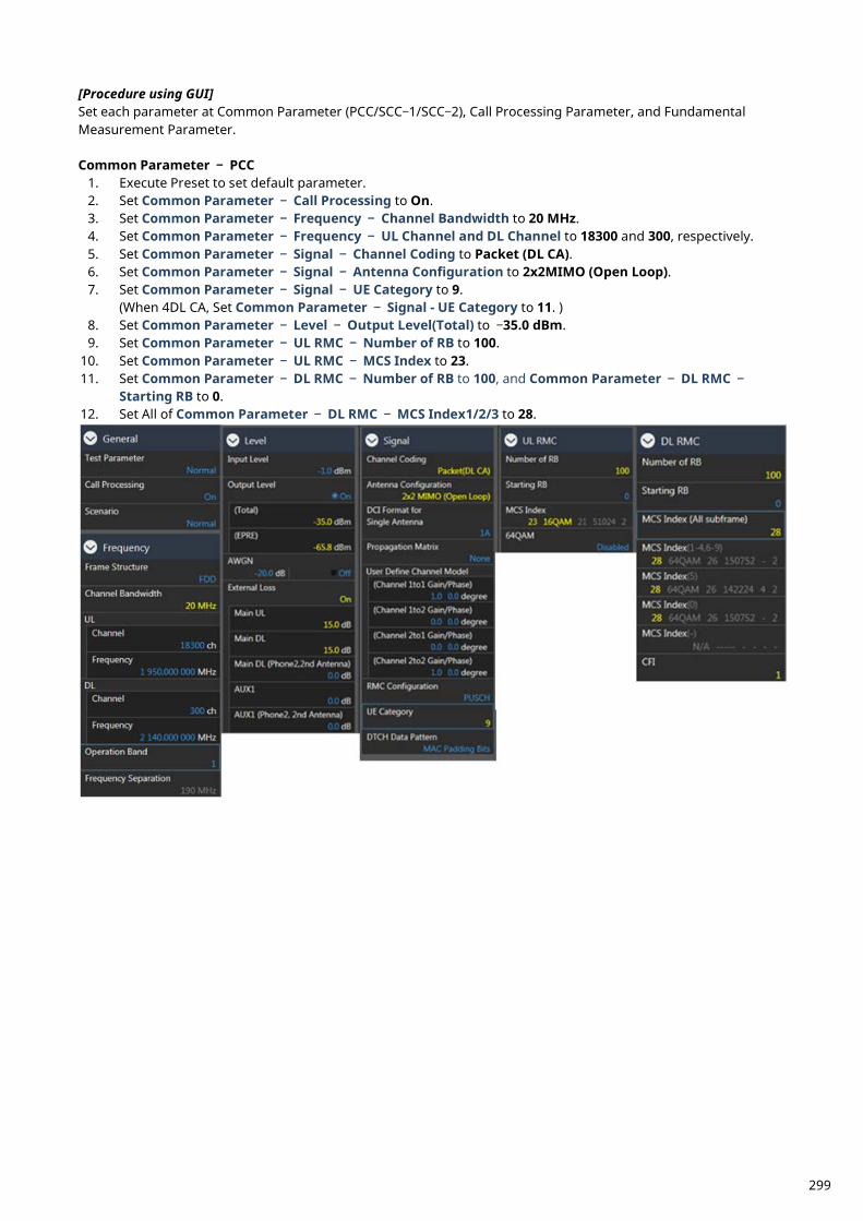
[Procedure using GUI] Set each parameter at Common Parameter (PCC/SCC–1/SCC–2), Call Processing Parameter, and Fundamental Measurement Parameter. Common Parameter – PCC
1. Execute Preset to set default parameter. 2. Set Common Parameter – Call Processing to On. 3. Set Common Parameter – Frequency – Channel Bandwidth to 20 MHz. 4. Set Common Parameter – Frequency – UL Channel and DL Channel to 18300 and 300, respectively. 5. Set Common Parameter – Signal – Channel Coding to Packet (DL CA). 6. Set Common Parameter – Signal – Antenna Configuration to 2x2MIMO (Open Loop). 7. Set Common Parameter – Signal – UE Category to 9.
(When 4DL CA, Set Common Parameter – Signal - UE Category to 11. ) 8. Set Common Parameter – Level – Output Level(Total) to –35.0 dBm. 9. Set Common Parameter – UL RMC – Number of RB to 100.
10. Set Common Parameter – UL RMC – MCS Index to 23. 11. Set Common Parameter – DL RMC – Number of RB to 100, and Common Parameter – DL RMC –
Starting RB to 0. 12. Set All of Common Parameter – DL RMC – MCS Index1/2/3 to 28.
299
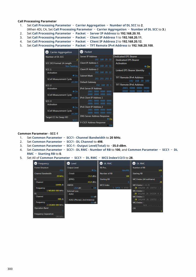
Call Processing Parameter 1. Set Call Processing Parameter – Carrier Aggregation – Number of DL SCC to 2.
(When 4DL CA, Set Call Processing Parameter – Carrier Aggregation – Number of DL SCC to 3.) 2. Set Call Processing Parameter – Packet – Server IP Address to 192.168.20.10. 3. Set Call Processing Parameter – Packet – Client IP Address 1 to 192.168.20.11. 4. Set Call Processing Parameter – Packet – Client IP Address 2 to 192.168.20.12. 5. Set Call Processing Parameter – Packet – TFT Remote IPv4 Address to 192.168.20.100.
Common Parameter - SCC-1
1. Set Common Parameter – SCC1 - Channel Bandwidth to 20 MHz. 2. Set Common Parameter – SCC1 - DL Channel to 498. 3. Set Common Parameter – SCC-1 - Output Level(Total) to –35.0 dBm. 4. Set Common Parameter – SCC1 - DL RMC - Number of RB to 100, and Common Parameter – SCC1 – DL
RMC – Starting RB to 0. 5. Set All of Common Parameter – SCC1 – DL RMC – MCS Index1/2/3 to 28.
300
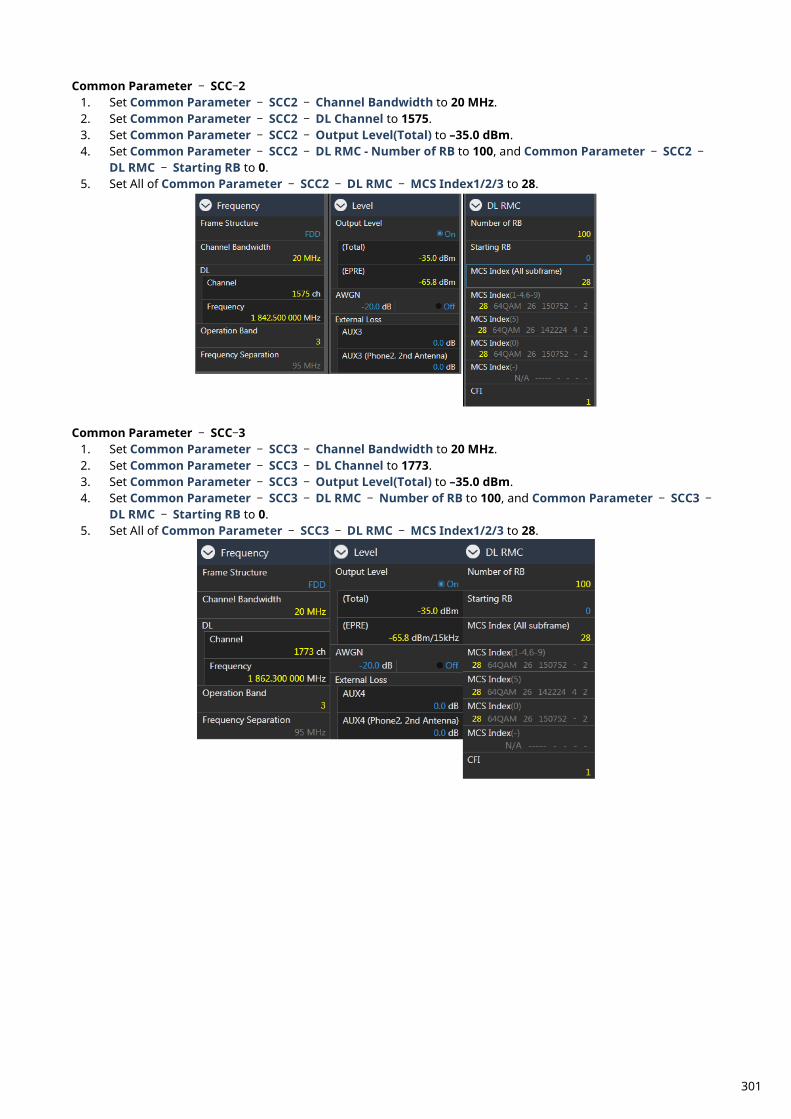
Common Parameter – SCC–2 1. Set Common Parameter – SCC2 – Channel Bandwidth to 20 MHz. 2. Set Common Parameter – SCC2 – DL Channel to 1575. 3. Set Common Parameter – SCC2 – Output Level(Total) to –35.0 dBm. 4. Set Common Parameter – SCC2 – DL RMC - Number of RB to 100, and Common Parameter – SCC2 –
DL RMC – Starting RB to 0. 5. Set All of Common Parameter – SCC2 – DL RMC – MCS Index1/2/3 to 28.
Common Parameter – SCC–3
1. Set Common Parameter – SCC3 – Channel Bandwidth to 20 MHz. 2. Set Common Parameter – SCC3 – DL Channel to 1773. 3. Set Common Parameter – SCC3 – Output Level(Total) to –35.0 dBm. 4. Set Common Parameter – SCC3 – DL RMC – Number of RB to 100, and Common Parameter – SCC3 –
DL RMC – Starting RB to 0. 5. Set All of Common Parameter – SCC3 – DL RMC – MCS Index1/2/3 to 28.
301
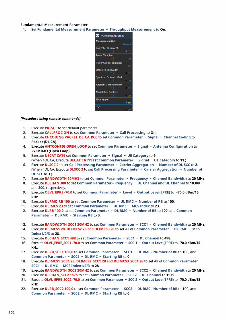
Fundamental Measurement Parameter 1. Set Fundamental Measurement Parameter – Throughput Measurement to On.
[Procedure using remote commands]
1. Execute PRESET to set default parameter. 2. Execute CALLPROC ON to set Common Parameter – Call Processing to On. 3. Execute CHCODING PACKET_DL_CA_PCC to set Common Parameter – Signal – Channel Coding to
Packet (DL CA). 4. Execute ANTCONFIG OPEN_LOOP to set Common Parameter – Signal – Antenna Configuration to
2x2MIMO (Open Loop). 5. Execute UECAT CAT9 set Common Parameter – Signal – UE Category to 9.
(When 4DL CA, Execute UECAT CAT11 set Common Parameter – Signal – UE Category to 11.) 6. Execute DLSCC 2 to set Call Processing Parameter – Carrier Aggregation – Number of DL SCC to 2.
(When 4DL CA, Execute DLSCC 3 to set Call Processing Parameter – Carrier Aggregation – Number of DL SCC to 3.)
7. Execute BANDWIDTH 20MHZ to set Common Parameter – Frequency – Channel Bandwidth to 20 MHz. 8. Execute DLCHAN 300 to set Common Parameter - Frequency – UL Channel and DL Channel to 18300
and 300, respectively. 9. Execute OLVL_EPRE -70.0 to set Common Parameter – Level – Output Level(EPRE) to –70.0 dBm/15
kHz. 10. Execute ULRMC_RB 100 to set Common Parameter – UL RMC – Number of RB to 100. 11. Execute ULIMCS 23 to set Common Parameter – UL RMC – MCS Index to 23. 12. Execute DLRB 100,0 to set Common Parameter – DL RMC – Number of RB to 100, and Common
Parameter – DL RMC – Starting RB to 0.
13. Execute BANDWIDTH_SCC1 20MHZ to set Common Parameter – SCC1 – Channel Bandwidth to 20 MHz. 14. Execute DLIMCS1 28, DLIMCS2 28 and DLIMCS3 28 to set All of Common Parameter – DL RMC – MCS
Index1/2/3 to 28. 15. Execute DLCHAN_SCC1 498 to set Common Parameter – SCC1 – DL Channel to 498. 16. Execute OLVL_EPRE_SCC1 -70.0 to set Common Parameter – SCC-1 – Output Level(EPRE) to –70.0 dBm/15
kHz. 17. Execute DLRB_SCC1 100,0 to set Common Parameter – SCC1 – DL RMC - Number of RB to 100, and
Common Parameter – SCC1 – DL RMC – Starting RB to 0. 18. Execute DLIMCS1_SCC1 28, DLIMCS2_SCC1 28 and DLIMCS3_SCC1 28 to set All of Common Parameter –
SCC1 – DL RMC – MCS Index1/2/3 to 28. 19. Execute BANDWIDTH_SCC2 20MHZ to set Common Parameter – SCC2 – Channel Bandwidth to 20 MHz. 20. Execute DLCHAN_SCC2 1575 to set Common Parameter – SCC2 – DL Channel to 1575. 21. Execute OLVL_EPRE_SCC2 -70.0 to set Common Parameter – SCC-2 – Output Level(EPRE) to –70.0 dBm/15
kHz. 22. Execute DLRB_SCC2 100,0 to set Common Parameter – SCC2 – DL RMC - Number of RB to 100, and
Common Parameter – SCC2 – DL RMC – Starting RB to 0.
302
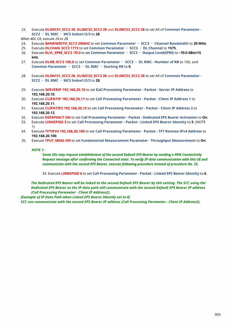
23. Execute DLIMCS1_SCC2 28, DLIMCS2_SCC2 28 and DLIMCS3_SCC2 28 to set All of Common Parameter -
SCC2 – DL RMC – MCS Index1/2/3 to 28. When 4DL CA, execute 24 to 28 24. Execute BANDWIDTH_SCC3 20MHZ to set Common Parameter – SCC3 – Channel Bandwidth to 20 MHz. 25. Execute DLCHAN_SCC3 1773 to set Common Parameter – SCC3 – DL Channel to 1575. 26. Execute OLVL_EPRE_SCC3 -70.0 to set Common Parameter – SCC3 – Output Level(EPRE) to –70.0 dBm/15
kHz. 27. Execute DLRB_SCC3 100,0 to set Common Parameter – SCC3 – DL RMC - Number of RB to 100, and
Common Parameter – SCC3 – DL RMC – Starting RB to 0.
28. Execute DLIMCS1_SCC2 28, DLIMCS2_SCC2 28 and DLIMCS3_SCC2 28 to set All of Common Parameter - SCC2 – DL RMC – MCS Index1/2/3 to 28.
29. Execute SERVERIP 192,168,20,10 to set Call Processing Parameter - Packet - Server IP Address to 192.168.20.10.
30. Execute CLIENTIP 192,168,20,11 to set Call Processing Parameter - Packet - Client IP Address 1 to 192.168.20.11.
31. Execute CLIENTIP2 192,168,20,12 to set Call Processing Parameter - Packet - Client IP Address 2 to 192.168.20.12.
32. Execute DEDEPSACT ON to set Call Processing Parameter - Packet - Dedicated EPS Bearer Activation to On. 33. Execute LINKEPSID 5 to set Call Processing Parameter - Packet - Linked EPS Bearer Identity to 5. (NOTE
1) 34. Execute TFTIPV4 192,168,20,100 to set Call Processing Parameter - Packet - TFT Remote IPv4 Address to
192.168.20.100. 35. Execute TPUT_MEAS ON to set Fundamental Measurement Parameter - Throughput Measurement to On.
NOTE 1: Some UEs may request establishment of the second Default EPS Bearer by sending a PDN Connectivity Request message after confirming the Connected state. To verify IP data communication with this UE and communicate with the second EPS Bearer, execute following procedure instead of procedure No. 33.
33. Execute LINKEPSID 6 to set Call Processing Parameter - Packet - Linked EPS Bearer Identity to 6.
The Dedicated EPS Bearer will be linked to the second Default EPS Bearer by this setting. The SCC using the Dedicated EPS Bearer as the IP data path will communicate with the second Default EPS Bearer IP address (Call Processing Parameter - Client IP Address2).
[Example of IP Data Path when Linked EPS Bearer Identity set to 6] SCC can communicate with the second EPS Bearer IP address (Call Processing Parameter - Client IP Address2).
303
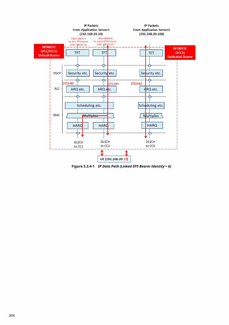
Figure 5.3.4-1 IP Data Path (Linked EPS Bearer Identity = 6)
304
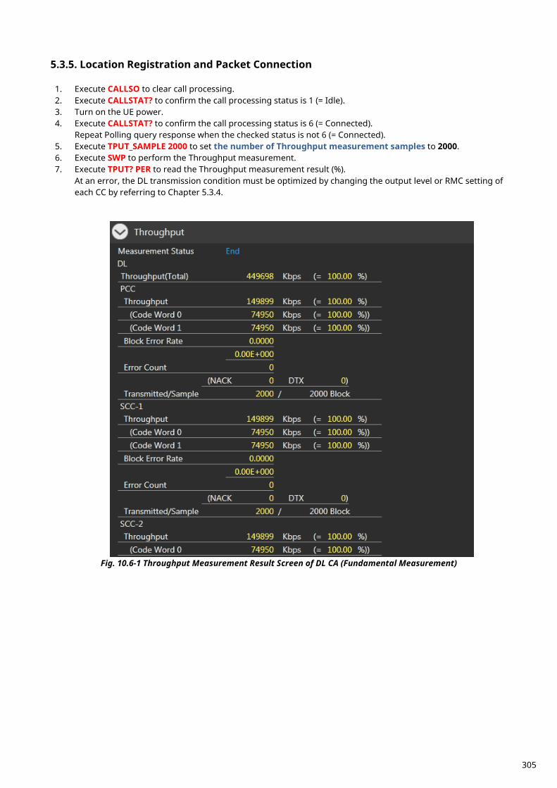
Location Registration and Packet Connection 5.3.5.
1. Execute CALLSO to clear call processing. 2. Execute CALLSTAT? to confirm the call processing status is 1 (= Idle). 3. Turn on the UE power. 4. Execute CALLSTAT? to confirm the call processing status is 6 (= Connected).
Repeat Polling query response when the checked status is not 6 (= Connected). 5. Execute TPUT_SAMPLE 2000 to set the number of Throughput measurement samples to 2000. 6. Execute SWP to perform the Throughput measurement. 7. Execute TPUT? PER to read the Throughput measurement result (%).
At an error, the DL transmission condition must be optimized by changing the output level or RMC setting of each CC by referring to Chapter 5.3.4.
Fig. 10.6-1 Throughput Measurement Result Screen of DL CA (Fundamental Measurement)
305
TCP/UDP Throughput 5.3.6. This chapter explains TCP/UDP throughput measurement using the Iperf software for downlink throughput tests. Uplink throughput measurement is supported by switching the application server and client PCs.
1. Open two Command Prompt windows on the Client PC and execute [cd c:¥] to change to the directory containing Iperf.exe. (If the DUT is a smartphone type, open the iperf application)
2. Run the following command to put the client PC into the wait status. TCP: [iperf -s -w 2M -i 1 -p 50000] UDP: [iperf -s -u -w 2M -i 1 -p 50000]
(If the DUT is a smartphone, open the iperf application) TCP: [-s -w 2M -i 1 -p 50000] UDP: [-s -u -w 2M -i 1 -p 50000]
3. Open the Command Prompt window on Application Server 1/2 and execute [cd c:¥] to change to the directory containing Iperf.exe.
[Case1:Linked EPS Bearer Identity = 5, Client IP Address = 192.168.20.11] 4. Run the following commands to send data from Application Server 1 and 2.
TCP from Application Server1: [iperf -c 192.168.20.11 -B 192.168.20.10 -w 2M -t 100000 -i 1 -p 50000] TCP from Application Server2: [iperf -c 192.168.20.11 -B 192.168.20.100 -w 2M -t 100000 -i 1 -p 50000] UDP from Application Server1: [iperf -c 192.168.20.11 -B 192.168.20.10 -b 300M -w 2M -t 100000 -i 1 -p 50000] UDP from Application Server2: [iperf -c 192.168.20.11 -B 192.168.20.100 -b 300M -w 2M -t 100000 -i 1 -p 50000] [Case2:Linked EPS Bearer Identity = 6, Client IPAddress2 = 192.168.20.12]
4. Run the following commands to send data from Application Server 1 and 2.
TCP from Application Server1: [iperf -c 192.168.20.12 -B 192.168.20.10 -w 2M -t 100000 -i 1 -p 50000] TCP from Application Server2: [iperf -c 192.168.20.12 -B 192.168.20.100 -w 2M -t 100000 -i 1 -p 50000] UDP from Application Server1: [iperf -c 192.168.20.12 -B 192.168.20.10 -b 300M -w 2M -t 100000 -i 1 -p 50000] UDP from Application Server2: [iperf -c 192.168.20.12 -B 192.168.20.100 -b 300M -w 2M -t 100000 -i 1 -p 50000]
5. The IP data throughput is displayed by the iperf application on the client server.
Note: Refer to B.3, adjust the buffer size (“-w” option argument) to match the performance of the Application
Server and the data rate. Change the port number (“-p” option argument) to match the Application Server. The same port number may be used by other applications on the PC.
306
IP Data Application 5.4. This chapter describes ping execution and TCP/UDP throughput verification using Iperf in MT8821C’s LTE measurement software.
ping 5.4.1. Described in the procedure below is the ping execution sequence for an IPv4 Packet-connected UE. The ping command is as follows.
ping 192.168.20.11 -w 1000 -l 50000 -S 192.168.20.10 1. Perform IPv4 connection procedure in chapter 5.1.5 and 5.1.6 to establish UE Packet connection. 2. Execute PINGDSTIP S1,192,168,20,11 to set PING - Destination IPv4 Address of server 1 to 192.168.20.11. 3. Execute PINGIP S1,IPV4 to set PING - IP Type of server 1 to IPv4. 4. Execute PINGW S1,1000 to set PING - Interval of server 1 to 1000. 5. Execute PINGL S1,32 to set PING - Buffer Size of server 1 to 32byte. 6. Execute RSLTAREA IPDATATAB to open IP Data tab. 7. Execute PINGSINGLS S1 to execute ping. 8. Confirm the result of the ping on the screen.
NOTE: Use Application Server1,2 IP address described in chapter 5.3.2.2 as the server address where
the ping is sent. The server address is specified by the “-s” option in the ping command.
iperf 5.4.2. Described in the procedure below is the TCP/UDP throughput verification sequence using iperf for an IPv4 Packet-connected UE. <When UDP> The iperf command is as follows.
Server1 : iperf -c 192.168.20.11 -B 192.168.20.10 –b 300M –p 50000 –w 2M –l 1000 –t 100 –i 1 Server2 : iperf -c 192.168.20.11 -B 192.168.20.100 –b 300M –p 50000 –w 2M –l 1000 –t 100 –i 1
1. Perform IPv4 connection procedure in chapter 5.3.4 and 5.3.5 to establish UE Packet connection. 2. Execute IPFMODE S1,CLIENT to set Iperf - Iperf Mode of server 1 to Client. 3. Execute IPFIP S1,IPV4 to set Iperf - IP Type of server 1 to IPv4. 4. Execute IPFPRTCL S1,UDP to set Iperf - IP Protocol of server 1 to UDP. 5. Execute IPFDSTIP S1,192,168,20,11 to set Iperf - Destination IPv4 Address of server 1 to 192.168.20.11. 6. Execute IPFB S1,300 to set Iperf - Bandwidth of server 1 to 300. 7. Execute IPFB_UNIT S1,MBITS to set Iperf - Bandwidth Unit of server 1 to Mbits/sec. 8. Execute IPFP S1,50000 to set Iperf - Port Number of server 1 to 50000. 9. Execute IPFW S1,2 to set Iperf - Window Size of server 1 to 2. 10. Execute IPFW S1,MBYTES to set Iperf - Window Size Unit of server 1 to Mbytes. 11. Execute IPFL S1,1000 to set Iperf - Frame Length of server 1 to 1000. 12. Execute IPFT S1,100 to set Iperf - Time of server 1 to 100. 13. Repeat steps 2 to 12 with argument S1 replaced by S2 to configure Server2 settings. 14. Execute RSLTAREA IPDATATAB to open IP Data tab. 15. Start iperf in the DUT then execute the following command.
When DUT is PC : iperf -s -u -w 2M -i 1 -p 50000 When DUT is Smartphone : -s -u -w 2M -i 1 -p 50000
16. Execute IPERFSINGLS BOTH to start UDP transmission by iperf. 17. Confirm the throughput result of the iperf on the DUT. <When TCP> The iperf command is as follows.
Server1 : iperf -c 192.168.20.11 -B 192.168.20.10 –p 50000 –w 2M –l 1000 –t 100 –i 1 Server2 : iperf -c 192.168.20.11 -B 192.168.20.100 –p 50000 –w 2M –l 1000 –t 100 –i 1
1. Perform IPv4 connection procedure in chapter 5.3.4 and 5.3.5 to establish UE Packet connection. 2. Execute IPFMODE S1,CLIENT to set Iperf - Iperf Mode of server 1 to Client. 3. Execute IPFIP S1,IPV4 to set Iperf - IP Type of server 1 to IPv4. 4. Execute IPFPRTCL S1,TCP to set Iperf - IP Protocol of server 1 to TCP.
307
5. Execute IPFDSTIP S1,192,168,20,11 to set Iperf - Destination IPv4 Address of server 1 to 192.168.20.11. 6. Execute IPFP S1,50000 to set Iperf - Port Number of server 1 to 50000. 7. Execute IPFW S1,2 to set Iperf - Window Size of server 1 to 2. 8. Execute IPFW S1,MBYTES to set Iperf - Window Size Unit of server 1 to Mbytes. 9. Execute IPFL S1,1000 to set Iperf - Frame Length of server 1 to 1000. 10. Execute IPFT S1,100 to set Iperf - Time of server 1 to 100. 11. Repeat steps 2 to 10 with argument S1 replaced by S2 to configure Server2 settings. 12. Execute RSLTAREA IPDATATAB to open IP Data tab. 13. Start iperf in the DUT then execute the following command.
When DUT is PC : iperf -s -w 2M -i 1 -p 50000 When DUT is Smartphone : -s -w 2M -i 1 -p 50000
14. Execute IPERFSINGLS BOTH to start TCP transmission by iperf. 15. Confirm the throughput result of the iperf on the DUT.
NOTE: Use Application Server1,2 IP address described in chapter 5.3.2.2 as the server address where
the data is sent. The server address is specified by the “-B” option in the iperf command.
308
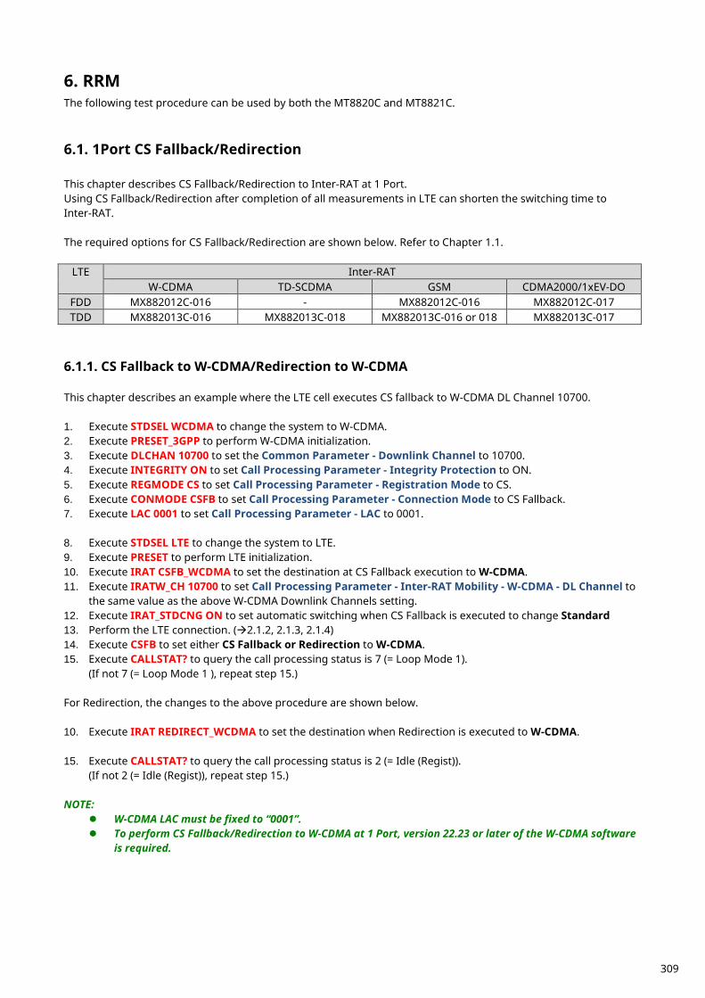
RRM 6.The following test procedure can be used by both the MT8820C and MT8821C.
1Port CS Fallback/Redirection 6.1. This chapter describes CS Fallback/Redirection to Inter-RAT at 1 Port. Using CS Fallback/Redirection after completion of all measurements in LTE can shorten the switching time to Inter-RAT. The required options for CS Fallback/Redirection are shown below. Refer to Chapter 1.1.
LTE Inter-RAT W-CDMA TD-SCDMA GSM CDMA2000/1xEV-DO
FDD MX882012C-016 - MX882012C-016 MX882012C-017 TDD MX882013C-016 MX882013C-018 MX882013C-016 or 018 MX882013C-017
CS Fallback to W-CDMA/Redirection to W-CDMA 6.1.1. This chapter describes an example where the LTE cell executes CS fallback to W-CDMA DL Channel 10700. 1. Execute STDSEL WCDMA to change the system to W-CDMA. 2. Execute PRESET_3GPP to perform W-CDMA initialization. 3. Execute DLCHAN 10700 to set the Common Parameter - Downlink Channel to 10700. 4. Execute INTEGRITY ON to set Call Processing Parameter - Integrity Protection to ON. 5. Execute REGMODE CS to set Call Processing Parameter - Registration Mode to CS. 6. Execute CONMODE CSFB to set Call Processing Parameter - Connection Mode to CS Fallback. 7. Execute LAC 0001 to set Call Processing Parameter - LAC to 0001.
8. Execute STDSEL LTE to change the system to LTE. 9. Execute PRESET to perform LTE initialization. 10. Execute IRAT CSFB_WCDMA to set the destination at CS Fallback execution to W-CDMA. 11. Execute IRATW_CH 10700 to set Call Processing Parameter - Inter-RAT Mobility - W-CDMA - DL Channel to
the same value as the above W-CDMA Downlink Channels setting. 12. Execute IRAT_STDCNG ON to set automatic switching when CS Fallback is executed to change Standard 13. Perform the LTE connection. (2.1.2, 2.1.3, 2.1.4) 14. Execute CSFB to set either CS Fallback or Redirection to W-CDMA. 15. Execute CALLSTAT? to query the call processing status is 7 (= Loop Mode 1).
(If not 7 (= Loop Mode 1 ), repeat step 15.) For Redirection, the changes to the above procedure are shown below. 10. Execute IRAT REDIRECT_WCDMA to set the destination when Redirection is executed to W-CDMA. 15. Execute CALLSTAT? to query the call processing status is 2 (= Idle (Regist)).
(If not 2 (= Idle (Regist)), repeat step 15.) NOTE:
W-CDMA LAC must be fixed to “0001”. To perform CS Fallback/Redirection to W-CDMA at 1 Port, version 22.23 or later of the W-CDMA software
is required.
309
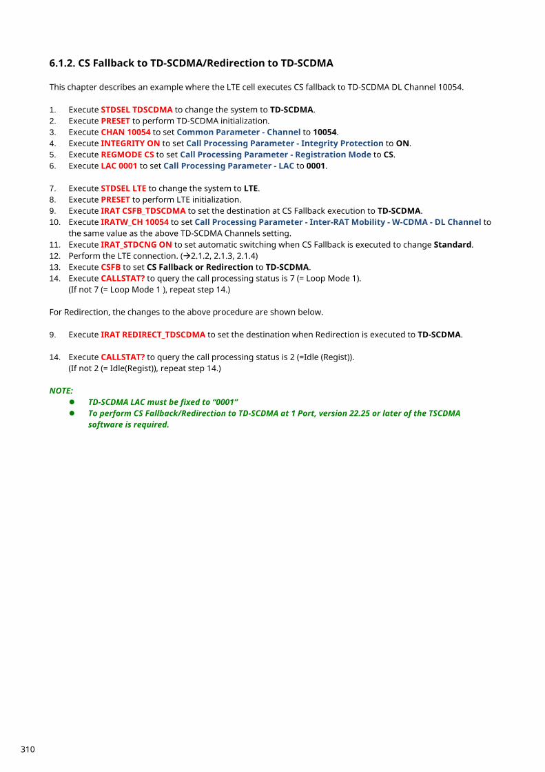
CS Fallback to TD-SCDMA/Redirection to TD-SCDMA 6.1.2. This chapter describes an example where the LTE cell executes CS fallback to TD-SCDMA DL Channel 10054. 1. Execute STDSEL TDSCDMA to change the system to TD-SCDMA. 2. Execute PRESET to perform TD-SCDMA initialization. 3. Execute CHAN 10054 to set Common Parameter - Channel to 10054. 4. Execute INTEGRITY ON to set Call Processing Parameter - Integrity Protection to ON. 5. Execute REGMODE CS to set Call Processing Parameter - Registration Mode to CS. 6. Execute LAC 0001 to set Call Processing Parameter - LAC to 0001.
7. Execute STDSEL LTE to change the system to LTE. 8. Execute PRESET to perform LTE initialization. 9. Execute IRAT CSFB_TDSCDMA to set the destination at CS Fallback execution to TD-SCDMA. 10. Execute IRATW_CH 10054 to set Call Processing Parameter - Inter-RAT Mobility - W-CDMA - DL Channel to
the same value as the above TD-SCDMA Channels setting. 11. Execute IRAT_STDCNG ON to set automatic switching when CS Fallback is executed to change Standard. 12. Perform the LTE connection. (2.1.2, 2.1.3, 2.1.4) 13. Execute CSFB to set CS Fallback or Redirection to TD-SCDMA. 14. Execute CALLSTAT? to query the call processing status is 7 (= Loop Mode 1).
(If not 7 (= Loop Mode 1 ), repeat step 14.) For Redirection, the changes to the above procedure are shown below. 9. Execute IRAT REDIRECT_TDSCDMA to set the destination when Redirection is executed to TD-SCDMA. 14. Execute CALLSTAT? to query the call processing status is 2 (=Idle (Regist)).
(If not 2 (= Idle(Regist)), repeat step 14.) NOTE:
TD-SCDMA LAC must be fixed to “0001” To perform CS Fallback/Redirection to TD-SCDMA at 1 Port, version 22.25 or later of the TSCDMA
software is required.
310
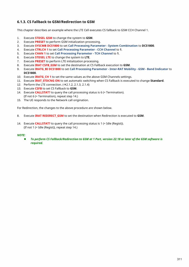
CS Fallback to GSM/Redirection to GSM 6.1.3. This chapter describes an example where the LTE Cell executes CS fallback to GSM CCH Channel 1. 1. Execute STDSEL GSM to change the system to GSM. 2. Execute PRESET to perform GSM initialization processing. 3. Execute SYSCMB DCS1800 to set Call Processing Parameter - System Combination to DCS1800. 4. Execute CTRLCH 1 to set Call Processing Parameter - CCH Channel to 1. 5. Execute CHAN 1 to set Call Processing Parameter - TCH Channel to 1. 6. Execute STDSEL LTE to change the system to LTE. 7. Execute PRESET to perform LTE initialization processing. 8. Execute IRAT CSFB_GSM to set the destination at CS Fallback execution to GSM. 9. Execute IRATG_BI DCS1800 to set Call Processing Parameter - Inter-RAT Mobility - GSM - Band Indicator to
DCS1800. 10. Execute IRATG_CH 1 to set the same values as the above GSM Channels settings. 11. Execute IRAT_STDCNG ON to set automatic switching when CS Fallback is executed to change Standard. 12. Perform the LTE connection. (2.1.2, 2.1.3, 2.1.4) 13. Execute CSFB to set CS Fallback to GSM. 14. Execute CALLSTAT? to query the call processing status is 6 (= Termination).
(If not 6 (= Termination), repeat step 14.) 15. The UE responds to the Network call origination. For Redirection, the changes to the above procedure are shown below. 8. Execute IRAT REDIRECT_GSM to set the destination when Redirection is executed to GSM. 14. Execute CALLSTAT? to query the call processing status is 1 (= Idle (Regist)).
(If not 1 (= Idle (Regist)), repeat step 14.) NOTE:
To perform CS Fallback/Redirection to GSM at 1 Port, version 22.18 or later of the GSM software is required.
311
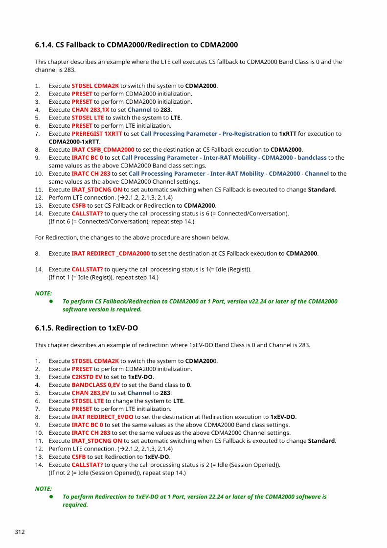
CS Fallback to CDMA2000/Redirection to CDMA2000 6.1.4. This chapter describes an example where the LTE cell executes CS fallback to CDMA2000 Band Class is 0 and the channel is 283. 1. Execute STDSEL CDMA2K to switch the system to CDMA2000. 2. Execute PRESET to perform CDMA2000 initialization. 3. Execute PRESET to perform CDMA2000 initialization. 4. Execute CHAN 283,1X to set Channel to 283. 5. Execute STDSEL LTE to switch the system to LTE. 6. Execute PRESET to perform LTE initialization. 7. Execute PREREGIST 1XRTT to set Call Processing Parameter - Pre-Registration to 1xRTT for execution to
CDMA2000-1xRTT. 8. Execute IRAT CSFB_CDMA2000 to set the destination at CS Fallback execution to CDMA2000. 9. Execute IRATC BC 0 to set Call Processing Parameter - Inter-RAT Mobility - CDMA2000 - bandclass to the
same values as the above CDMA2000 Band class settings. 10. Execute IRATC CH 283 to set Call Processing Parameter - Inter-RAT Mobility - CDMA2000 - Channel to the
same values as the above CDMA2000 Channel settings. 11. Execute IRAT_STDCNG ON to set automatic switching when CS Fallback is executed to change Standard. 12. Perform LTE connection. (2.1.2, 2.1.3, 2.1.4) 13. Execute CSFB to set CS Fallback or Redirection to CDMA2000. 14. Execute CALLSTAT? to query the call processing status is 6 (= Connected/Conversation).
(If not 6 (= Connected/Conversation), repeat step 14.) For Redirection, the changes to the above procedure are shown below. 8. Execute IRAT REDIRECT _CDMA2000 to set the destination at CS Fallback execution to CDMA2000. 14. Execute CALLSTAT? to query the call processing status is 1(= Idle (Regist)).
(If not 1 (= Idle (Regist)), repeat step 14.) NOTE:
To perform CS Fallback/Redirection to CDMA2000 at 1 Port, version v22.24 or later of the CDMA2000 software version is required.
Redirection to 1xEV-DO 6.1.5. This chapter describes an example of redirection where 1xEV-DO Band Class is 0 and Channel is 283. 1. Execute STDSEL CDMA2K to switch the system to CDMA2000. 2. Execute PRESET to perform CDMA2000 initialization. 3. Execute C2KSTD EV to set to 1xEV-DO. 4. Execute BANDCLASS 0,EV to set the Band class to 0. 5. Execute CHAN 283,EV to set Channel to 283. 6. Execute STDSEL LTE to change the system to LTE. 7. Execute PRESET to perform LTE initialization. 8. Execute IRAT REDIRECT_EVDO to set the destination at Redirection execution to 1xEV-DO. 9. Execute IRATC BC 0 to set the same values as the above CDMA2000 Band class settings. 10. Execute IRATC CH 283 to set the same values as the above CDMA2000 Channel settings. 11. Execute IRAT_STDCNG ON to set automatic switching when CS Fallback is executed to change Standard. 12. Perform LTE connection. (2.1.2, 2.1.3, 2.1.4) 13. Execute CSFB to set Redirection to 1xEV-DO. 14. Execute CALLSTAT? to query the call processing status is 2 (= Idle (Session Opened)).
(If not 2 (= Idle (Session Opened)), repeat step 14.) NOTE:
To perform Redirection to 1xEV-DO at 1 Port, version 22.24 or later of the CDMA2000 software is required.
312
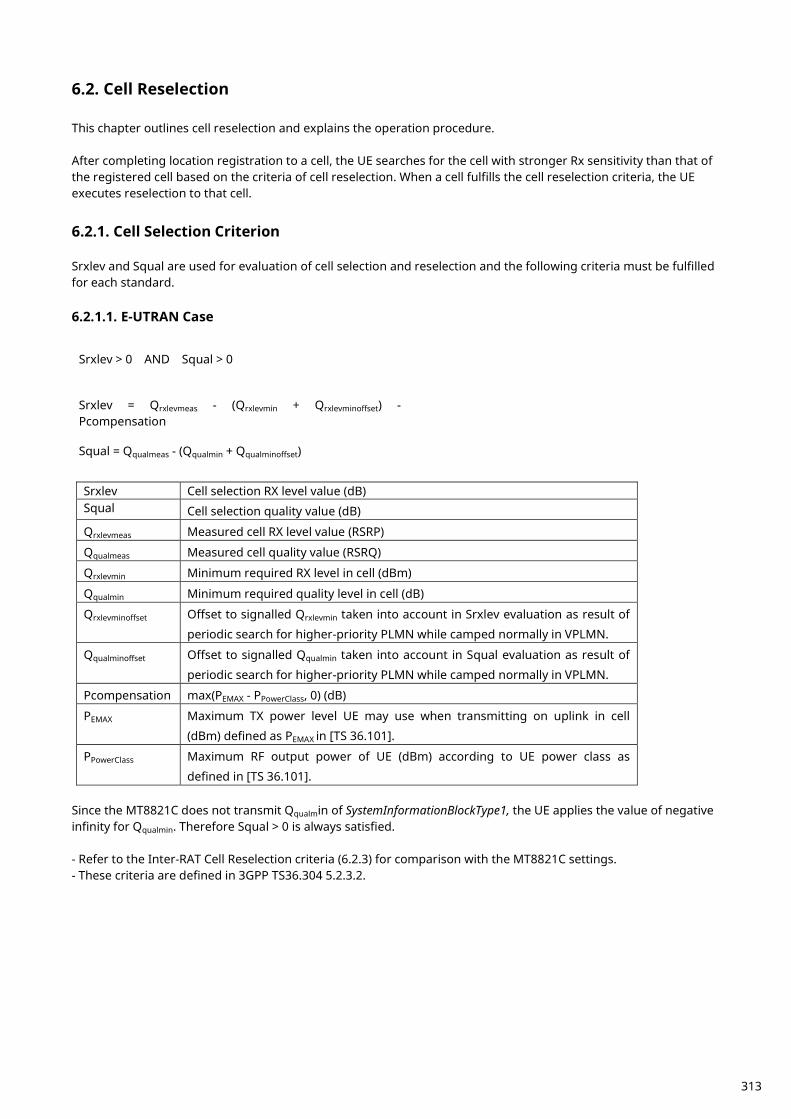
Cell Reselection 6.2. This chapter outlines cell reselection and explains the operation procedure. After completing location registration to a cell, the UE searches for the cell with stronger Rx sensitivity than that of the registered cell based on the criteria of cell reselection. When a cell fulfills the cell reselection criteria, the UE executes reselection to that cell.
Cell Selection Criterion 6.2.1. Srxlev and Squal are used for evaluation of cell selection and reselection and the following criteria must be fulfilled for each standard. 6.2.1.1. E-UTRAN Case
Srxlev > 0 AND Squal > 0
Srxlev = Qrxlevmeas - (Qrxlevmin + Qrxlevminoffset) - Pcompensation
Squal = Qqualmeas - (Qqualmin + Qqualminoffset)
Srxlev Cell selection RX level value (dB) Squal Cell selection quality value (dB)
Qrxlevmeas Measured cell RX level value (RSRP)
Qqualmeas Measured cell quality value (RSRQ)
Qrxlevmin Minimum required RX level in cell (dBm)
Qqualmin Minimum required quality level in cell (dB)
Qrxlevminoffset Offset to signalled Qrxlevmin taken into account in Srxlev evaluation as result of
periodic search for higher-priority PLMN while camped normally in VPLMN.
Qqualminoffset Offset to signalled Qqualmin taken into account in Squal evaluation as result of
periodic search for higher-priority PLMN while camped normally in VPLMN.
Pcompensation max(PEMAX - PPowerClass, 0) (dB)
PEMAX Maximum TX power level UE may use when transmitting on uplink in cell
(dBm) defined as PEMAX in [TS 36.101].
PPowerClass Maximum RF output power of UE (dBm) according to UE power class as
defined in [TS 36.101]. Since the MT8821C does not transmit Qqualmin of SystemInformationBlockType1, the UE applies the value of negative infinity for Qqualmin. Therefore Squal > 0 is always satisfied. - Refer to the Inter-RAT Cell Reselection criteria (6.2.3) for comparison with the MT8821C settings. - These criteria are defined in 3GPP TS36.304 5.2.3.2.
313
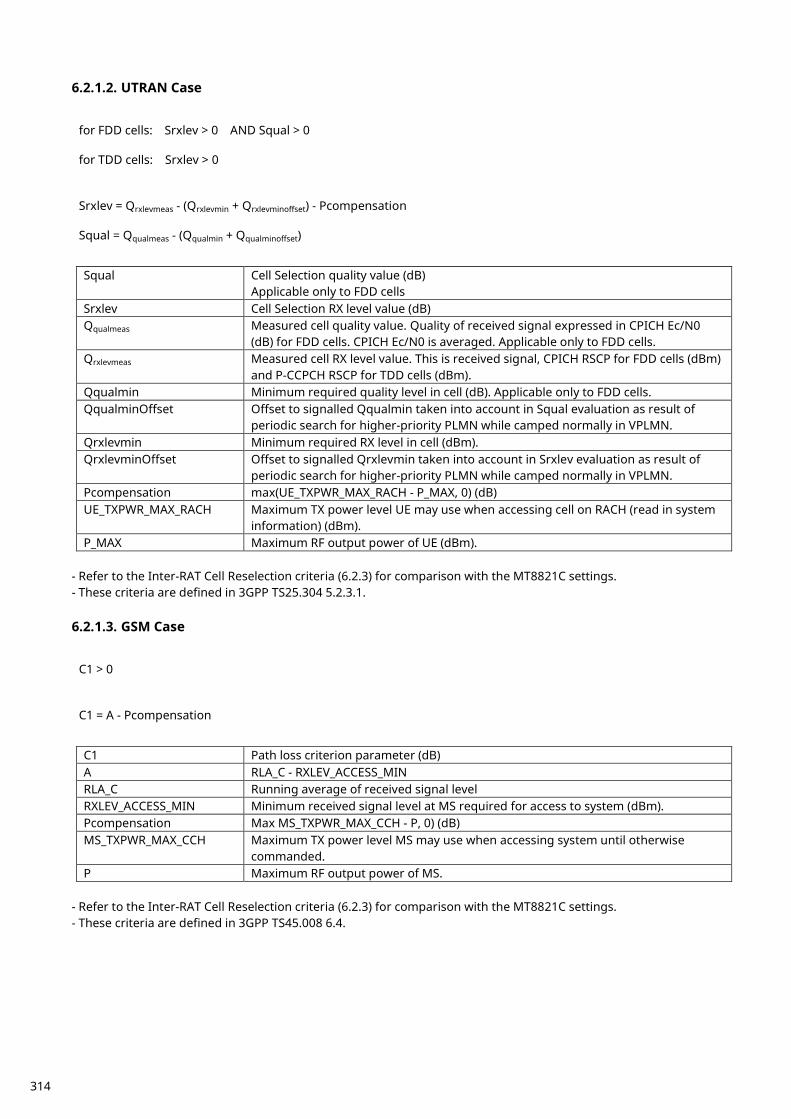
6.2.1.2. UTRAN Case
for FDD cells: Srxlev > 0 AND Squal > 0
for TDD cells: Srxlev > 0
Srxlev = Qrxlevmeas - (Qrxlevmin + Qrxlevminoffset) - Pcompensation
Squal = Qqualmeas - (Qqualmin + Qqualminoffset)
Squal Cell Selection quality value (dB)
Applicable only to FDD cells Srxlev Cell Selection RX level value (dB) Qqualmeas Measured cell quality value. Quality of received signal expressed in CPICH Ec/N0
(dB) for FDD cells. CPICH Ec/N0 is averaged. Applicable only to FDD cells. Qrxlevmeas Measured cell RX level value. This is received signal, CPICH RSCP for FDD cells (dBm)
and P-CCPCH RSCP for TDD cells (dBm). Qqualmin Minimum required quality level in cell (dB). Applicable only to FDD cells. QqualminOffset Offset to signalled Qqualmin taken into account in Squal evaluation as result of
periodic search for higher-priority PLMN while camped normally in VPLMN. Qrxlevmin Minimum required RX level in cell (dBm). QrxlevminOffset Offset to signalled Qrxlevmin taken into account in Srxlev evaluation as result of
periodic search for higher-priority PLMN while camped normally in VPLMN. Pcompensation max(UE_TXPWR_MAX_RACH - P_MAX, 0) (dB) UE_TXPWR_MAX_RACH Maximum TX power level UE may use when accessing cell on RACH (read in system
information) (dBm). P_MAX Maximum RF output power of UE (dBm).
- Refer to the Inter-RAT Cell Reselection criteria (6.2.3) for comparison with the MT8821C settings. - These criteria are defined in 3GPP TS25.304 5.2.3.1. 6.2.1.3. GSM Case
C1 > 0
C1 = A - Pcompensation
C1 Path loss criterion parameter (dB) A RLA_C - RXLEV_ACCESS_MIN RLA_C Running average of received signal level RXLEV_ACCESS_MIN Minimum received signal level at MS required for access to system (dBm). Pcompensation Max MS_TXPWR_MAX_CCH - P, 0) (dB) MS_TXPWR_MAX_CCH Maximum TX power level MS may use when accessing system until otherwise
commanded. P Maximum RF output power of MS.
- Refer to the Inter-RAT Cell Reselection criteria (6.2.3) for comparison with the MT8821C settings. - These criteria are defined in 3GPP TS45.008 6.4.
314
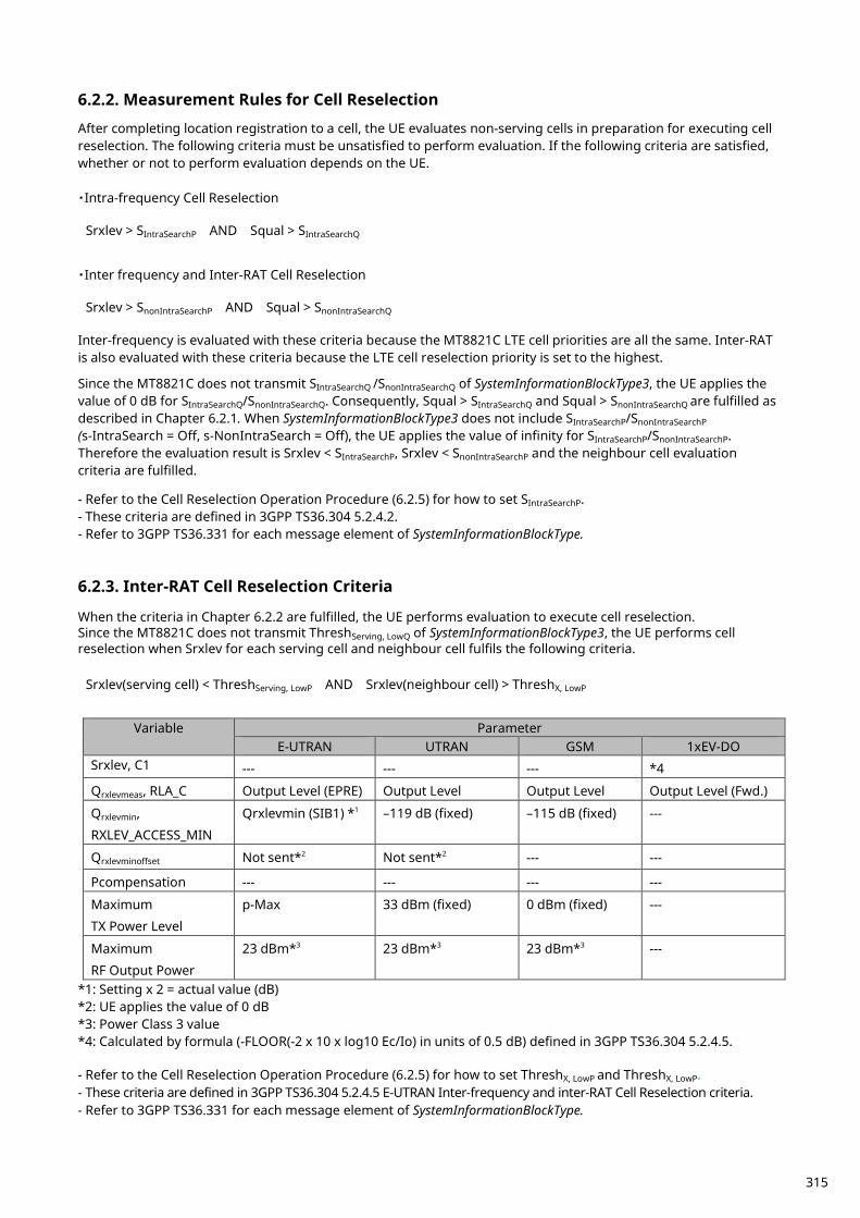
Measurement Rules for Cell Reselection 6.2.2. After completing location registration to a cell, the UE evaluates non-serving cells in preparation for executing cell reselection. The following criteria must be unsatisfied to perform evaluation. If the following criteria are satisfied, whether or not to perform evaluation depends on the UE. ・Intra-frequency Cell Reselection
Srxlev > SIntraSearchP AND Squal > SIntraSearchQ
・Inter frequency and Inter-RAT Cell Reselection
Srxlev > SnonIntraSearchP AND Squal > SnonIntraSearchQ
Inter-frequency is evaluated with these criteria because the MT8821C LTE cell priorities are all the same. Inter-RAT is also evaluated with these criteria because the LTE cell reselection priority is set to the highest. Since the MT8821C does not transmit SIntraSearchQ /SnonIntraSearchQ of SystemInformationBlockType3, the UE applies the value of 0 dB for SIntraSearchQ/SnonIntraSearchQ. Consequently, Squal > SIntraSearchQ and Squal > SnonIntraSearchQ are fulfilled as described in Chapter 6.2.1. When SystemInformationBlockType3 does not include SIntraSearchP/SnonIntraSearchP (s-IntraSearch = Off, s-NonIntraSearch = Off), the UE applies the value of infinity for SIntraSearchP/SnonIntraSearchP. Therefore the evaluation result is Srxlev < SIntraSearchP, Srxlev < SnonIntraSearchP and the neighbour cell evaluation criteria are fulfilled. - Refer to the Cell Reselection Operation Procedure (6.2.5) for how to set SIntraSearchP. - These criteria are defined in 3GPP TS36.304 5.2.4.2. - Refer to 3GPP TS36.331 for each message element of SystemInformationBlockType.
Inter-RAT Cell Reselection Criteria 6.2.3. When the criteria in Chapter 6.2.2 are fulfilled, the UE performs evaluation to execute cell reselection. Since the MT8821C does not transmit ThreshServing, LowQ of SystemInformationBlockType3, the UE performs cell reselection when Srxlev for each serving cell and neighbour cell fulfils the following criteria.
Srxlev(serving cell) < ThreshServing, LowP AND Srxlev(neighbour cell) > ThreshX, LowP
Variable Parameter
E-UTRAN UTRAN GSM 1xEV-DO Srxlev, C1 --- --- --- *4
Qrxlevmeas, RLA_C Output Level (EPRE) Output Level Output Level Output Level (Fwd.)
Qrxlevmin,
RXLEV_ACCESS_MIN
Qrxlevmin (SIB1) *1 –119 dB (fixed) –115 dB (fixed) ---
Qrxlevminoffset Not sent*2 Not sent*2 --- ---
Pcompensation --- --- --- ---
Maximum
TX Power Level
p-Max 33 dBm (fixed) 0 dBm (fixed) ---
Maximum
RF Output Power
23 dBm*3 23 dBm*3 23 dBm*3 ---
*1: Setting x 2 = actual value (dB) *2: UE applies the value of 0 dB *3: Power Class 3 value *4: Calculated by formula (-FLOOR(-2 x 10 x log10 Ec/Io) in units of 0.5 dB) defined in 3GPP TS36.304 5.2.4.5. - Refer to the Cell Reselection Operation Procedure (6.2.5) for how to set ThreshX, LowP and ThreshX, LowP. - These criteria are defined in 3GPP TS36.304 5.2.4.5 E-UTRAN Inter-frequency and inter-RAT Cell Reselection criteria. - Refer to 3GPP TS36.331 for each message element of SystemInformationBlockType.
315
Intra-Frequency and Equal Inter-Frequency Cell Reselection Criteria 6.2.4. When the criteria in Chapter 6.2.2 are fulfilled, the UE ranks cells to perform cell reselection. When the ranking Rn
of the following neighbour cell is greater than the ranking Rs of the serving cell, the UE performs cell reselection.
Rs = Qmeas,s + QHyst
Rn = Qmeas,n + Qoffset
Qmeas RSRP measurement quantity used at cell reselection. Qoffset For intra-frequency: Equals to Qoffsets,n, if Qoffsets,n is valid, otherwise this equals to zero.
For inter-frequency: Equals to Qoffsets,n plus Qoffsetfrequency, if Qoffsets,n is valid, otherwise
this equals to Qoffsetfrequency. The MT8821C sets QHyst of SystemInformationBlockType3 to dB0. For inter-frequency, only Qoffsetfrequency is used because the MT8821C does not transmit Qoffsets,n. - The Qmeas setting procedure is the same as Qrxlevmeas described in 6.2.3 Inter-RAT Cell Reselection Criteria. - Refer to 6.2.5 Cell Reselection Operation Procedure for how to set Qoffset. - These criteria are defined in 3GPP TS36.304 5.2.4.6.
Cell Reselection Procedure 6.2.5. To perform cell reselection, follow the procedure below. LTE (serving cell) operations are in blue and neighbor cell operations are in red.
NOTE 1: Perform initial condition setting (2.1.2) and external loss setting for each standard before performing cell reselection.
NOTE 2: TS36.521-3 specifies the margin for cell reselection criteria as at least 6 dB.
6.2.5.1. Inter-RAT(TD-SCDMA) Cell Reselection: TD-SCDMA is lower priority. 1. [TD-SCDMA] Execute CHAN 10054 to set Common Parameter - Channel to 10054. 2. [TD-SCDMA] Execute LVL OFF to set Common Parameter - Output Level to Off. 3. [LTE] Execute OLVL_EPRE -50.0 to set Common Parameter - Output Level (EPRE) to –50.0 (dBm/15 kHz). 4. [LTE] Execute QRXLEVMIN_SIB1 -70 to set Call Processing Parameter - Qrxlevmin (SIB1) to –70 (–140 dB). 5. [LTE] Execute SNONINTRA -1 to set Call Processing Parameter - s-NonIntraSearch to Off (∞ dB). 6. [LTE] Execute THSERVLOW 30 to set Call Processing Parameter - threshServingLow to 30 (60 dB). 7. [LTE] Execute NCATDSDLUARFCN 1,10054 to set the leftmost Inter RAT (TD-SCDMA) Cell - threshX-Low to
10054. 8. [LTE] Execute NCATDSTXLOW 0 to set Call Processing Parameter - Inter RAT (TD-SCDMA) Cell - threshX-Low
to 0 (0 dB). 9. [LTE] Turn on the UE power and perform location registration (2.1.3). 10. [TD-SCDMA] Execute LVL ON to set Common Parameter - Output Level to On. 11. [TD-SCDMA] Execute OLVL -30.0 to set Common Parameter - Output Level to –30.0 dBm. 12. [LTE] Execute OLVL_EPRE -75.0 to set Common Parameter - Output Level (EPRE) to –75.0 (dBm/15 kHz), and
wait a few seconds. 13. [TD-SCDMA] Execute CALLSTATIC? and check that the call processing static status is 2 (= Idle(Regist)). 6.2.5.2. Inter-RAT(W-CDMA) Cell Reselection: W-CDMA is lower priority. 1. [W-CDMA] Execute PRESET_3GPP to initialize to the value based on 3GPP. 2. [W-CDMA] Execute DLCHAN 10700 to set DL Channel to 10700. 3. [W-CDMA] Execute INTEGRITY ON to set Integrity Protection to On. 4. [W-CDMA] Execute REGMODE COMBINED to set Registration Mode to Combined. 5. [W-SCDMA] Execute LVL OFF to set Output Level to Off. 6. [LTE] Execute OLVL_EPRE -50.0 to set Output Level (EPRE) to –50.0 (dBm/15 kHz). 7. [LTE] Execute QRXLEVMIN_SIB1 -70 to set Qrxlevmin (SIB1) to –70 (–140 dB).
316
8. [LTE] Execute SNONINTRA -1 to set s-NonIntraSearch to Off (∞ dB). 9. [LTE] Execute THSERVLOW 30 to set threshServingLow to 30 (60 dB). 10. [LTE] Execute NCAWCDMADLUARFCN 1,10700 to set the leftmost Inter RAT (W-CDMA) Cell - UARFCN to
10700. 11. [LTE] Execute NCAWCDMATXLOW 0 to set Inter RAT (W-CDMA) Cell - threshX-Low to 0 (0 dB). 12. [LTE] Turn on the UE power and perform location registration (2.1.3). 13. [W-CDMA] Execute LVL ON to set Output Level to On. 14. [W-CDMA] Execute OLVL -30.0 to set Output Level to –30.0 dBm. 15. [LTE] Execute OLVL_EPRE -75.0 to set Output Level (EPRE) to –75.0 (dBm/15 kHz) and wait a few seconds. 16. [W-CDMA] Execute CALLSTAT? and check that the call processing static status is 2(= Idle (Regist)). 6.2.5.3. Inter-RAT(GSM) Cell Reselection: GSM is lower priority. 1. [GSM] Execute SYSCMB DCS1800 to set System Combination to GSM/DCS1800. 2. [GSM] Execute CTRLCH 1 to set CCH Channel to 1. 3. [GSM] Execute LVL OFF to set Output Level to Off. 4. [LTE] Execute OLVL_EPRE -50.0 to set Output Level (EPRE) to –50.0 (dBm/15 kHz). 5. [LTE] Execute QRXLEVMIN_SIB1 -70 to set Qrxlevmin (SIB1) to –70 (–140 dB). 6. [LTE] Execute SNONINTRA -1 to set s-NonIntraSearch to Off (∞ dB). 7. [LTE] Execute THSERVLOW 30 to set threshServingLow to 30 (60 dB). 8. [LTE] Execute NCABCCHARFCN 1,1,DCS1800 to set the leftmost Inter RAT (GSM) Cell - BCCH-ARFCN and
Band to 1 and DCS, respectively. 9. [LTE] Execute NCAGSMTXLOW 0 to set Inter RAT (GSM) Cell - threshX-Low to 0 (0 dB). 10. [LTE] Turn on the UE perform and perform location registration (2.1.3). 11. [GSM] Execute LVL ON to set Output Level to On. 12. [GSM] Execute OLVL -30.0 to set Output Level to –30.0 dBm. 13. [LTE] Execute OLVL_EPRE -75.0 to set Output Level (EPRE) to –75.0 (dBm/15 kHz) and wait a few seconds. 14. [GSM] Execute CALLSTAT? and check that the call processing static status is 2(= Idle (Regist)).
6.2.5.4. Inter-RAT(1xEV-DO) Cell Reselection: 1xEV-DO is lower priority. 1. [1xEV-DO] Execute C2KSTD EV to set Standard to 1xEV-DO. 2. [1xEV-DO] Execute BANDCLASS 1 to set Band Class to 1. 3. [1xEV-DO] Execute CHAN 375 to set Channel to 375. 4. [1xEV-DO] Execute LVL OFF to set Output Level to Off. 5. [LTE] Execute OLVL_EPRE -50.0 to set Output Level (EPRE) to –50.0 (dBm/15 kHz). 6. [LTE] Execute QRXLEVMIN_SIB1 -70 to set Qrxlevmin (SIB1) to –70 (–140 dB). 7. [LTE] Execute SNONINTRA -1 to set s-NonIntraSearch to Off (∞ dB). 8. [LTE] Execute THSERVLOW 30 to set threshServingLow to 30 (60 dB). 9. [LTE] Execute NCAEVDOARFCN 1,375 to set the leftmost Inter RAT (1xEV-DO) Cell - ARFCN to 375. 10. [LTE] Execute NCAEVDOBAND BC1 to set Inter RAT (1xEV-DO) Cell - Band Class to bc1. 11. [LTE] Execute NCAEVDOTXLOW 2 to set Inter RAT (1xEV-DO) Cell - threshX-Low to 2 (–1.0 dB). 12. [LTE] Turn on the UE power and perform location registration (2.1.3). 13. [1xEV-DO] Execute LVL ON to set Output Level to On. 14. [1xEV-DO] Execute CALLSTATIC? and check that the call processing static status is 2(= Idle (Regist)). 6.2.5.5. Inter-Frequency Cell Reselection: Inter-Frequency has same priority. 1. [InterFreq] Execute DLCHAN 0 to set DL Channel to 0. 2. [InterFreq] Execute TAC 000A to set TAC to 000A. 3. [InterFreq] Execute LVL OFF to set Output Level to Off. 4. [LTE] Execute OLVL_EPRE -50.0 to set Output Level (EPRE) to –50.0 (dBm/15 kHz). 5. [LTE] Execute QRXLEVMIN_SIB1 -70 to set Qrxlevmin (SIB1) to –70 (–140 dB). 6. [LTE] Execute SNONINTRA -1 to set s-NonIntraSearch to Off (∞ dB). 7. [LTE] Execute NCAINTERFREQ 1,0 to set the leftmost Inter Frequency Cell - DL Channel to 0. 8. [LTE] Execute NCAINTERQOFFSET 0dB to set Inter Frequency Cell - q-OffsetFreq to 0 dB. 9. [LTE] Execute NCAINTERQOFFSETCELL 1,-4dB to set the leftmost Inter Frequency Cell - q-OffsetCell to –4
dB. 10. [LTE] Execute NCAINTERCELLID 1,0 to set the leftmost Inter Frequency Cell - Cell ID to 0.
317
11. [LTE] Turn on the UE power and perform location registration (2.1.3). 12. [InterFreq] Execute LVL ON to set Output Level to On. 13. [InterFreq] Execute OLVL_EPRE -60.0 to set Output Level (EPRE) to –60.0 (dBm/15 kHz). 14. [LTE] Execute OLVL_EPRE -75.0 to set Output Level (EPRE) to –75.0 (dBm/15 kHz) and wait a few seconds. 15. [InterFreq] Execute CALLSTAT? and check that the call processing static status is 2(= Idle(Regist)). 6.2.5.6. Intra-Frequency Cell Reselection 1. [IntraFreq] Execute CELLID 100 to set Cell ID to 100. 2. [IntraFreq] Execute TAC 000A to set TAC to 000A. 3. [IntraFreq] Execute LVL OFF to set Output Level to Off. 4. [LTE] Execute OLVL_EPRE -50.0 to set Output Level (EPRE) to –50.0 (dBm/15 kHz). 5. [LTE] Execute QRXLEVMIN_SIB1 -70 to set Qrxlevmin (SIB1) to –70 (–140 dB). 6. [LTE] Execute SINTRA -1 to set s-IntraSearch to Off (∞ dB). 7. [LTE] Execute NCAINTRAFREQ 1,100 to set the leftmost Intra Frequency Cell - Cell ID to 100. 8. [LTE] Execute NCAINTRAQOFFSET 0 to set Intra Frequency Cell - q-OffsetCell to 0 dB. 9. [LTE] Turn on the UE power and perform location registration (2.1.3). 10. [IntraFreq] Execute LVL ON to set Output Level to On. 11. [IntraFreq] Execute OLVL_EPRE -60.0 to set Output Level (EPRE) to –60.0 (dBm/15 kHz). 12. [LTE] Execute OLVL_EPRE -70.0 to set Output Level (EPRE) to –70.0 (dBm/15 kHz) and wait a few seconds. 13. [IntraFreq] Execute CALLSTAT? and check that the call processing static status is 2(= Idle (Regist)).
318
Measurement Report 6.3. This chapter describes the Measurement Report. This function can verify the Inter-RAT measurement function and receiver characteristics for neighboring cells, such as E-UTRA inter-frequency/intra-frequency, Inter-RAT UTRA FDD/TDD, GSM, CDMA2000 in RRC_CONNECTED state.
Initial Condition Setting 6.3.1. In this and following chapters, the initial settings are 480 ms for Measurement Report - Interval, and Periodical for Measurement Report - Trigger Type. Changes can be made if necessary.
1. Execute MEASREP_INTVAL 480 to send UE Report every 480 ms. 2. Execute MEASREP_TRG PERIODICAL to set Measurement Report - Trigger Type to Periodical.
Measurement Report Procedure 6.3.2.6.3.2.1. Measurement Report for LTE This chapter describes the UE Report for the Serving Cell (LTE).
1. Execute CALLRFR to initialize the UE Report value. 2. Execute NEIGHCELLMEAS OFF to set Neighbour Cell Measurement to OFF. 3. Connect in Test Mode. (2.3) 4. Execute MEASREP ON to request UE Report. 5. Execute RSRP? FLAG and check if the Response is 1 to receive the UE Report. 6. Execute RSRP? to read the RSRP value. 7. To read again, return to Step 4 and continue.
For a one-time UE Report, the changes to the procedure are shown below. These changes can be applied to the following procedures.
5. Execute MEASREP OFF. 6. Execute MEASREP_ONCE to request UE report only once.
6.3.2.2. Measurement Report for Intra-Frequency This chapter describes the UE Report for LTE and Intra-Frequency. In the example, the Cell ID for Intra-Frequency is set to 100 and TAC is set to 000A. A UE Report for the Neighbour Cell requires signal input to the UE. Signal Input is also required for the following procedures.
1. [LTE] Execute CALLRFR to initialize the UE Report value. 2. [LTE] Execute NCAINTRAFREQ 1,100 to set leftmost Intra Frequency Cell - Cell ID to 100. 3. [LTE] Execute NEIGHCELLMEAS INTRAFREQ to set Neighbour Cell Measurement to Intra Frequency. 4. [IntraFreq] Execute CELLID 100 to set Cell ID to 100. 5. [IntraFreq] Execute TAC 000A to set TAC to 000A. 6. [LTE] Connect in the Test Mode. (2.3) 7. [LTE] Execute MEASREP ON to request UE Report. 8. [LTE] Execute MREP_LTE? FLAG and check if the Response is 1 to receive the UE Report for Intra-Frequency. 9. [LTE] Execute MREP_LTE? to read the Cell ID, RSRP, and RSRQ values.
10. To read again, return to Step 8 and continue.
319
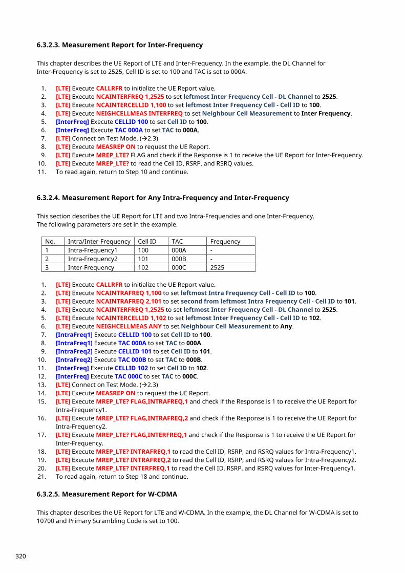
6.3.2.3. Measurement Report for Inter-Frequency This chapter describes the UE Report of LTE and Inter-Frequency. In the example, the DL Channel for Inter-Frequency is set to 2525, Cell ID is set to 100 and TAC is set to 000A.
1. [LTE] Execute CALLRFR to initialize the UE Report value. 2. [LTE] Execute NCAINTERFREQ 1,2525 to set leftmost Inter Frequency Cell - DL Channel to 2525. 3. [LTE] Execute NCAINTERCELLID 1,100 to set leftmost Inter Frequency Cell - Cell ID to 100. 4. [LTE] Execute NEIGHCELLMEAS INTERFREQ to set Neighbour Cell Measurement to Inter Frequency. 5. [InterFreq] Execute CELLID 100 to set Cell ID to 100. 6. [InterFreq] Execute TAC 000A to set TAC to 000A. 7. [LTE] Connect on Test Mode. (2.3) 8. [LTE] Execute MEASREP ON to request the UE Report. 9. [LTE] Execute MREP_LTE? FLAG and check if the Response is 1 to receive the UE Report for Inter-Frequency.
10. [LTE] Execute MREP_LTE? to read the Cell ID, RSRP, and RSRQ values. 11. To read again, return to Step 10 and continue.
6.3.2.4. Measurement Report for Any Intra-Frequency and Inter-Frequency This section describes the UE Report for LTE and two Intra-Frequencies and one Inter-Frequency. The following parameters are set in the example.
No. Intra/Inter-Frequency Cell ID TAC Frequency 1 Intra-Frequency1 100 000A - 2 Intra-Frequency2 101 000B - 3 Inter-Frequency 102 000C 2525
1. [LTE] Execute CALLRFR to initialize the UE Report value. 2. [LTE] Execute NCAINTRAFREQ 1,100 to set leftmost Intra Frequency Cell - Cell ID to 100. 3. [LTE] Execute NCAINTRAFREQ 2,101 to set second from leftmost Intra Frequency Cell - Cell ID to 101. 4. [LTE] Execute NCAINTERFREQ 1,2525 to set leftmost Inter Frequency Cell - DL Channel to 2525. 5. [LTE] Execute NCAINTERCELLID 1,102 to set leftmost Inter Frequency Cell - Cell ID to 102. 6. [LTE] Execute NEIGHCELLMEAS ANY to set Neighbour Cell Measurement to Any. 7. [IntraFreq1] Execute CELLID 100 to set Cell ID to 100. 8. [IntraFreq1] Execute TAC 000A to set TAC to 000A. 9. [IntraFreq2] Execute CELLID 101 to set Cell ID to 101.
10. [IntraFreq2] Execute TAC 000B to set TAC to 000B. 11. [InterFreq] Execute CELLID 102 to set Cell ID to 102. 12. [InterFreq] Execute TAC 000C to set TAC to 000C. 13. [LTE] Connect on Test Mode. (2.3) 14. [LTE] Execute MEASREP ON to request the UE Report. 15. [LTE] Execute MREP_LTE? FLAG,INTRAFREQ,1 and check if the Response is 1 to receive the UE Report for
Intra-Frequency1. 16. [LTE] Execute MREP_LTE? FLAG,INTRAFREQ,2 and check if the Response is 1 to receive the UE Report for
Intra-Frequency2. 17. [LTE] Execute MREP_LTE? FLAG,INTERFREQ,1 and check if the Response is 1 to receive the UE Report for
Inter-Frequency. 18. [LTE] Execute MREP_LTE? INTRAFREQ,1 to read the Cell ID, RSRP, and RSRQ values for Intra-Frequency1. 19. [LTE] Execute MREP_LTE? INTRAFREQ,2 to read the Cell ID, RSRP, and RSRQ values for Intra-Frequency2. 20. [LTE] Execute MREP_LTE? INTERFREQ,1 to read the Cell ID, RSRP, and RSRQ values for Inter-Frequency1. 21. To read again, return to Step 18 and continue.
6.3.2.5. Measurement Report for W-CDMA This chapter describes the UE Report for LTE and W-CDMA. In the example, the DL Channel for W-CDMA is set to 10700 and Primary Scrambling Code is set to 100.
320
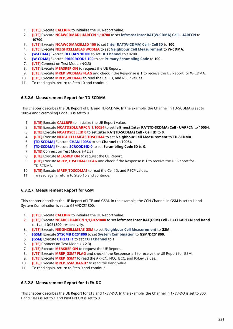
1. [LTE] Execute CALLRFR to initialize the UE Report value. 2. [LTE] Execute NCAWCDMADLUARFCN 1,10700 to set leftmost Inter RAT(W-CDMA) Cell - UARFCN to
10700. 3. [LTE] Execute NCAWCDMACELLID 100 to set Inter RAT(W-CDMA) Cell - Cell ID to 100. 4. [LTE] Execute NEIGHCELLMEAS WCDMA to set Neighbour Cell Measurement to W-CDMA. 5. [W-CDMA] Execute DLCHAN 10700 to set DL Channel to 10700. 6. [W-CDMA] Execute PRISCRCODE 100 to set Primary Scrambling Code to 100. 7. [LTE] Connect on Test Mode. (2.3) 8. [LTE] Execute MEASREP ON to request the UE Report. 9. [LTE] Execute MREP_WCDMA? FLAG and check if the Response is 1 to receive the UE Report for W-CDMA.
10. [LTE] Execute MREP_WCDMA? to read the Cell ID, and RSCP values. 11. To read again, return to Step 10 and continue.
6.3.2.6. Measurement Report for TD-SCDMA This chapter describes the UE Report of LTE and TD-SCDMA. In the example, the Channel in TD-SCDMA is set to 10054 and Scrambling Code ID is set to 0.
1. [LTE] Execute CALLRFR to initialize the UE Report value. 2. [LTE] Execute NCATDSDLUARFCN 1,10054 to set leftmost Inter RAT(TD-SCDMA) Cell - UARFCN to 10054. 3. [LTE] Execute NCATDSCELLID 0 to set Inter RAT(TD-SCDMA) Cell - Cell ID to 0. 4. [LTE] Execute NEIGHCELLMEAS TDSCDMA to set Neighbour Cell Measurement to TD-SCDMA. 5. [TD-SCDMA] Execute CHAN 10054 to set Channel to 10054. 6. [TD-SCDMA] Execute SCRCODEID 0 to set Scrambling Code ID to 0. 7. [LTE] Connect on Test Mode. (2.3) 8. [LTE] Execute MEASREP ON to request the UE Report. 9. [LTE] Execute MREP_TDSCDMA? FLAG and check if the Response is 1 to receive the UE Report for
TD-SCDMA. 10. [LTE] Execute MREP_TDSCDMA? to read the Cell ID, and RSCP values. 11. To read again, return to Step 10 and continue.
6.3.2.7. Measurement Report for GSM This chapter describes the UE Report of LTE and GSM. In the example, the CCH Channel in GSM is set to 1 and System Combination is set to GSM/DCS1800.
1. [LTE] Execute CALLRFR to initialize the UE Report value. 2. [LTE] Execute NCABCCHARFCN 1,1,DCS1800 to set leftmost Inter RAT(GSM) Cell - BCCH-ARFCN and Band
to 1 and DCS1800, respectively. 3. [LTE] Execute NEIGHCELLMEAS GSM to set Neighbour Cell Measurement to GSM. 4. [GSM] Execute SYSCMB DCS1800 to set System Combination to GSM/DCS1800. 5. [GSM] Execute CTRLCH 1 to set CCH Channel to 1. 6. [LTE] Connect on Test Mode. (2.3) 7. [LTE] Execute MEASREP ON to request the UE Report. 8. [LTE] Execute MREP_GSM? FLAG and check if the Response is 1 to receive the UE Report for GSM. 9. [LTE] Execute MREP_GSM? to read the ARFCN, NCC, BCC, and RxLev values.
10. [LTE] Execute MREP_GSM_BAND? to read the Band value. 11. To read again, return to Step 9 and continue. 6.3.2.8. Measurement Report for 1xEV-DO This chapter describes the UE Report for LTE and 1xEV-DO. In the example, the Channel in 1xEV-DO is set to 300, Band Class is set to 1 and Pilot PN Off is set to 0.
321
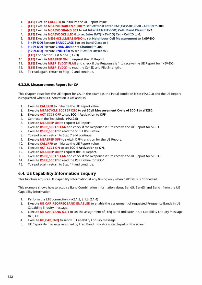
1. [LTE] Execute CALLRFR to initialize the UE Report value. 2. [LTE] Execute NCAEVDOARFCN 1,300 to set leftmost Inter RAT(1xEV-DO) Cell - ARFCN to 300. 3. [LTE] Execute NCAEVDOBAND BC1 to set Inter RAT(1xEV-DO) Cell - Band Class to bc1. 4. [LTE] Execute NCAEVDOCELLID 0 to set Inter RAT(1xEV-DO) Cell - Cell ID to 0. 5. [LTE] Execute NEIGHCELLMEAS EVDO to set Neighbour Cell Measurement to 1xEV-DO. 6. [1xEV-DO] Execute BANDCLASS 1 to set Band Class to 1. 7. [1xEV-DO] Execute CHAN 300 to set Channel to 300. 8. [1xEV-DO] Execute PNOFFS 0 to set Pilot PN Offset to 0. 9. [LTE] Connect on Test Mode. (2.3)
10. [LTE] Execute MEASREP ON to request the UE Report. 11. [LTE] Execute MREP_EVDO? FLAG and check if the Response is 1 to receive the UE Report for 1xEV-DO. 12. [LTE] Execute MREP_EVDO? to read the Cell ID and PilotStrength. 13. To read again, return to Step 12 and continue.
6.3.2.9. Measurement Report for CA This chapter describes the UE Report for CA. In the example, the initial condition is set (2.2.3) and the UE Report is requested when SCC Activation is Off and On.
1. Execute CALLRFR to initialize the UE Report value. 2. Execute MEASCYCLE_SCC1 SF1280 to set SCell Measurement Cycle of SCC-1 to sf1280. 3. Execute ACT_SCC1 OFF to set SCC-1 Activation to OFF. 4. Connect in the Test Mode. (2.2.5) 5. Execute MEASREP ON to request UE Report. 6. Execute RSRP_SCC1? FLAG and check if the Response is 1 to receive the UE Report for SCC-1. 7. Execute RSRP_SCC1? to read the SCC-1 RSRP value. 8. To read again, return to Step 7 and continue. 9. Execute MEASREP OFF to switch OFF transition for the UE Report.
10. Execute CALLRFR to initialize the UE Report value. 11. Execute ACT_SCC1 ON to set SCC-1 Activation to ON. 12. Execute MEASREP ON to request the UE Report. 13. Execute RSRP_SCC1? FLAG and check if the Response is 1 to receive the UE Report for SCC-1. 14. Execute RSRP_SCC1? to read the RSRP value for SCC-1. 15. To read again, return to Step 14 and continue.
UE Capability Information Enquiry 6.4.This function acquires UE Capability Information at any timing only when CallStatus is Connected. This example shows how to acquire Band Combination information about Band5, Band3, and Band1 from the UE Capability Information.
1. Perform the LTE connection. (2.1.2, 2.1.3, 2.1.4) 2. Execute UE_CAP_REQFREQBAND ENABLED to enable the assignment of requested Frequency Bands in UE
Capability Enquiry message. 3. Execute UE_CAP_BAND 5,3,1 to set the assignment of Freq Band Indicator in UE Capability Enquiry message
to 5,3,1. 4. Execute UE_CAP_ENQ to send UE Capability Enquiry message. 5. UE Capability message assigned by Freq Band Indicator is displayed on the screen
322

LTE VoLTE Echoback Test (MT8821C Only) 7. The following test procedures can be used for the MT8821C only.
LTE VoLTE Echoback Test 7.1. The VoLTE Echoback between the internal IMS server of the MT8821C and the UE can be tested by installing the MX882164C LTE VoLTE Echoback option in the MT8821C.
NOTES: The VoLTE Connection Test can be performed even without the MX882112C/13C–006 IP Data
Transfer Option License. The following test procedure is based on hands-on operation. Refer to the LTE measurement software operation manual for the basic operation and remote commands.
Connection Diagram 7.1.1.7.1.1.1. Connection Diagram for IP Data Verification using MT8821C
Figure 7.1.1-1 Connection Diagram for LTE VoLTE Echoback Test (MT8821C, using internal IMS server)
<Required Equipment> LTE mobile terminal supporting VoLTE connection
RF cable to connect MT8821C and LTE mobile terminal Crossover cable to connect MT8821C and application server
* Windows is a registered trademark of Microsoft Corporation in the USA and other countries.
323
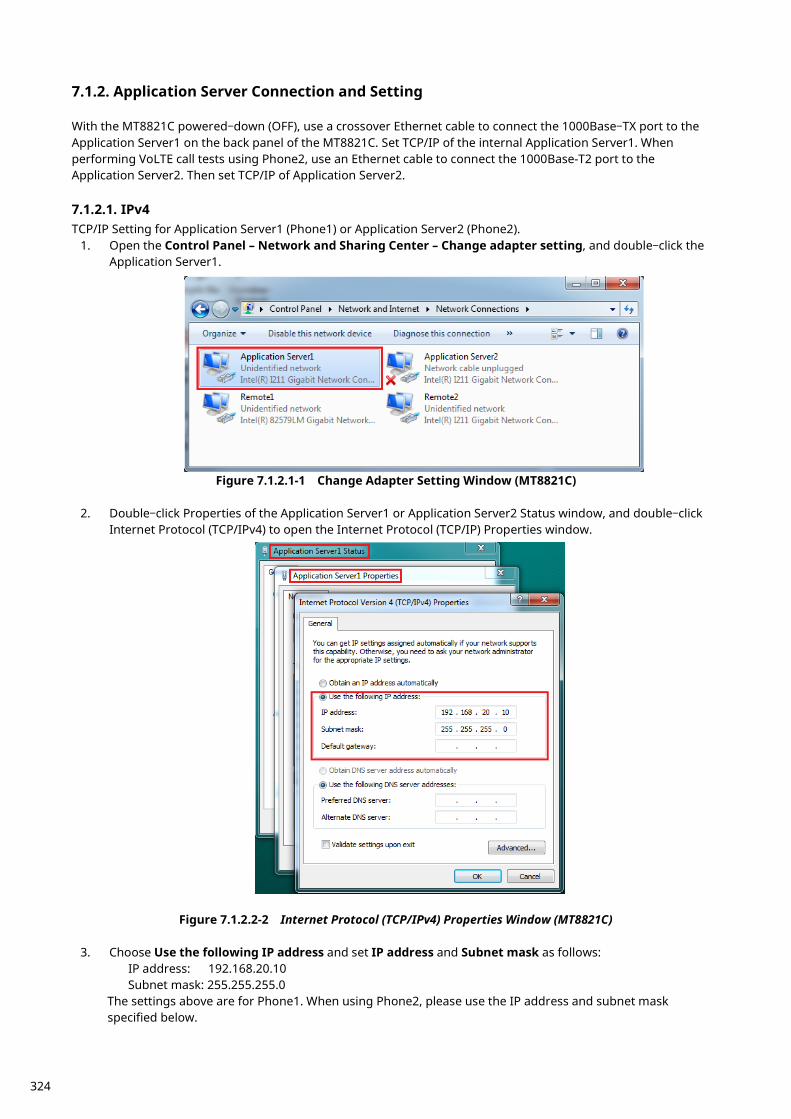
Application Server Connection and Setting 7.1.2. With the MT8821C powered–down (OFF), use a crossover Ethernet cable to connect the 1000Base–TX port to the Application Server1 on the back panel of the MT8821C. Set TCP/IP of the internal Application Server1. When performing VoLTE call tests using Phone2, use an Ethernet cable to connect the 1000Base-T2 port to the Application Server2. Then set TCP/IP of Application Server2. 7.1.2.1. IPv4 TCP/IP Setting for Application Server1 (Phone1) or Application Server2 (Phone2).
1. Open the Control Panel – Network and Sharing Center – Change adapter setting, and double–click the Application Server1.
Figure 7.1.2.1-1 Change Adapter Setting Window (MT8821C)
2. Double–click Properties of the Application Server1 or Application Server2 Status window, and double–click Internet Protocol (TCP/IPv4) to open the Internet Protocol (TCP/IP) Properties window.
Figure 7.1.2.2-2 Internet Protocol (TCP/IPv4) Properties Window (MT8821C)
3. Choose Use the following IP address and set IP address and Subnet mask as follows:
IP address: 192.168.20.10 Subnet mask: 255.255.255.0
The settings above are for Phone1. When using Phone2, please use the IP address and subnet mask specified below.
324
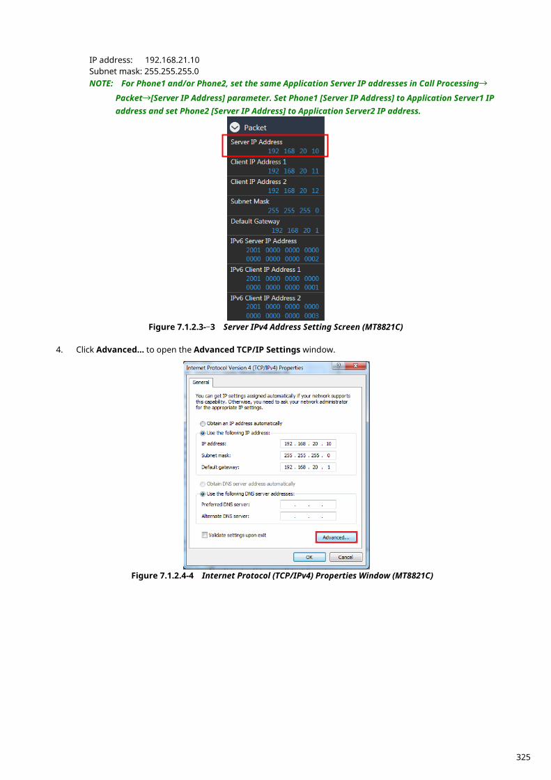
IP address: 192.168.21.10 Subnet mask: 255.255.255.0 NOTE: For Phone1 and/or Phone2, set the same Application Server IP addresses in Call Processing→
Packet→[Server IP Address] parameter. Set Phone1 [Server IP Address] to Application Server1 IP address and set Phone2 [Server IP Address] to Application Server2 IP address.
Figure 7.1.2.3-–3 Server IPv4 Address Setting Screen (MT8821C)
4. Click Advanced… to open the Advanced TCP/IP Settings window.
Figure 7.1.2.4-4 Internet Protocol (TCP/IPv4) Properties Window (MT8821C)
325
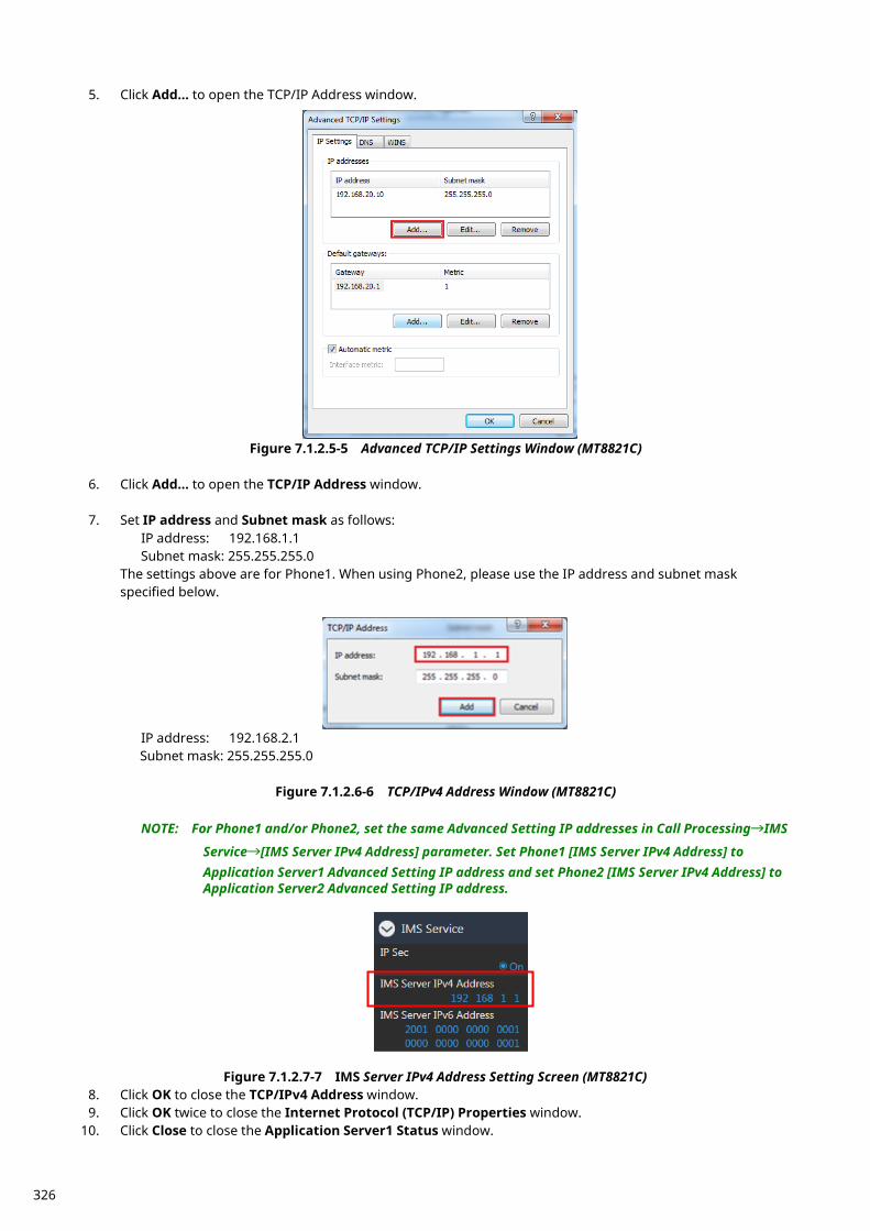
5. Click Add… to open the TCP/IP Address window.
Figure 7.1.2.5-5 Advanced TCP/IP Settings Window (MT8821C)
6. Click Add… to open the TCP/IP Address window.
7. Set IP address and Subnet mask as follows: IP address: 192.168.1.1 Subnet mask: 255.255.255.0
The settings above are for Phone1. When using Phone2, please use the IP address and subnet mask specified below.
IP address: 192.168.2.1 Subnet mask: 255.255.255.0
Figure 7.1.2.6-6 TCP/IPv4 Address Window (MT8821C)
NOTE: For Phone1 and/or Phone2, set the same Advanced Setting IP addresses in Call Processing→IMS
Service→[IMS Server IPv4 Address] parameter. Set Phone1 [IMS Server IPv4 Address] to Application Server1 Advanced Setting IP address and set Phone2 [IMS Server IPv4 Address] to Application Server2 Advanced Setting IP address.
Figure 7.1.2.7-7 IMS Server IPv4 Address Setting Screen (MT8821C)
8. Click OK to close the TCP/IPv4 Address window. 9. Click OK twice to close the Internet Protocol (TCP/IP) Properties window.
10. Click Close to close the Application Server1 Status window.
326
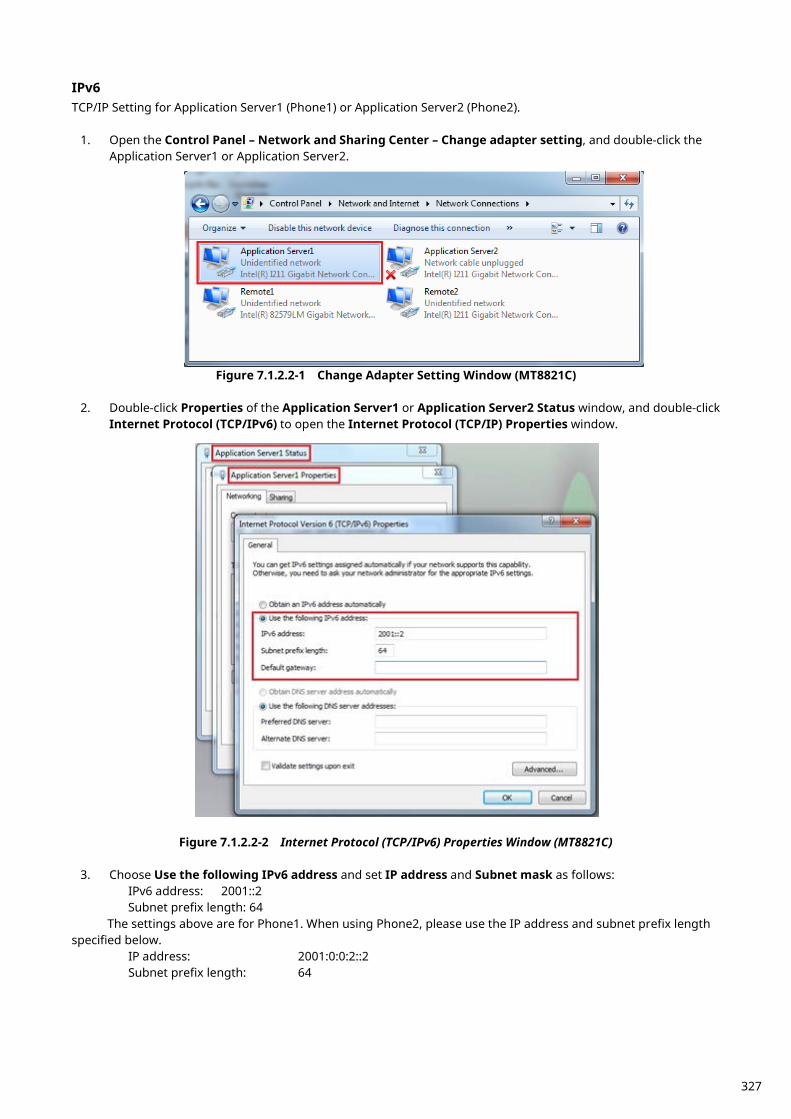
IPv6 TCP/IP Setting for Application Server1 (Phone1) or Application Server2 (Phone2).
1. Open the Control Panel – Network and Sharing Center – Change adapter setting, and double-click the Application Server1 or Application Server2.
Figure 7.1.2.2-1 Change Adapter Setting Window (MT8821C)
2. Double-click Properties of the Application Server1 or Application Server2 Status window, and double-click Internet Protocol (TCP/IPv6) to open the Internet Protocol (TCP/IP) Properties window.
Figure 7.1.2.2-2 Internet Protocol (TCP/IPv6) Properties Window (MT8821C)
3. Choose Use the following IPv6 address and set IP address and Subnet mask as follows:
IPv6 address: 2001::2 Subnet prefix length: 64
The settings above are for Phone1. When using Phone2, please use the IP address and subnet prefix length specified below.
IP address: 2001:0:0:2::2 Subnet prefix length: 64
327
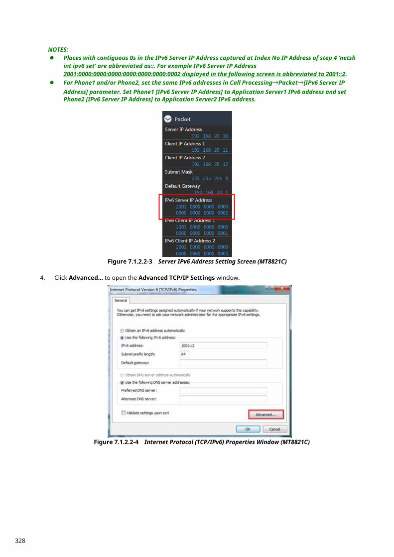
NOTES: Places with contiguous 0s in the IPv6 Server IP Address captured at Index No IP Address of step 4 ‘netsh
int ipv6 set’ are abbreviated as::. For example IPv6 Server IP Address 2001:0000:0000:0000:0000:0000:0000:0002 displayed in the following screen is abbreviated to 2001::2.
For Phone1 and/or Phone2, set the same IPv6 addresses in Call Processing→Packet→[IPv6 Server IP Address] parameter. Set Phone1 [IPv6 Server IP Address] to Application Server1 IPv6 address and set Phone2 [IPv6 Server IP Address] to Application Server2 IPv6 address.
Figure 7.1.2.2-3 Server IPv6 Address Setting Screen (MT8821C)
4. Click Advanced… to open the Advanced TCP/IP Settings window.
Figure 7.1.2.2-4 Internet Protocol (TCP/IPv6) Properties Window (MT8821C)
328
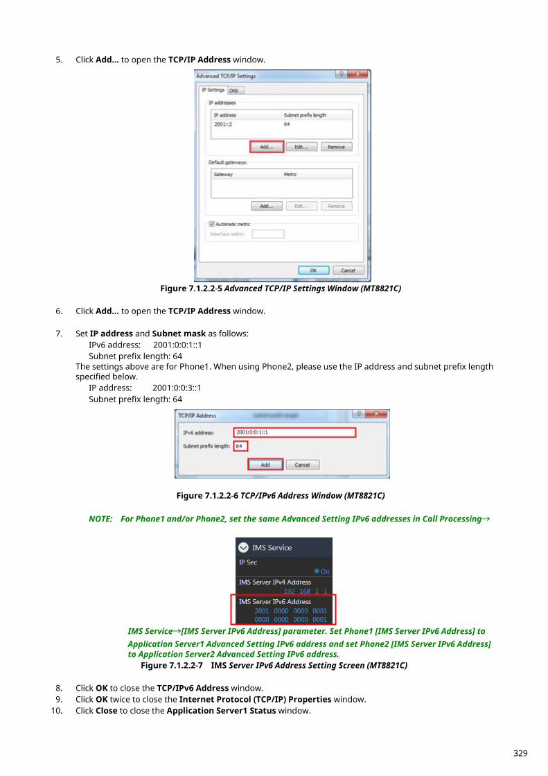
5. Click Add… to open the TCP/IP Address window.
Figure 7.1.2.2-5 Advanced TCP/IP Settings Window (MT8821C)
6. Click Add… to open the TCP/IP Address window.
7. Set IP address and Subnet mask as follows: IPv6 address: 2001:0:0:1::1 Subnet prefix length: 64
The settings above are for Phone1. When using Phone2, please use the IP address and subnet prefix length specified below.
IP address: 2001:0:0:3::1 Subnet prefix length: 64
Figure 7.1.2.2-6 TCP/IPv6 Address Window (MT8821C)
NOTE: For Phone1 and/or Phone2, set the same Advanced Setting IPv6 addresses in Call Processing→
IMS Service→[IMS Server IPv6 Address] parameter. Set Phone1 [IMS Server IPv6 Address] to Application Server1 Advanced Setting IPv6 address and set Phone2 [IMS Server IPv6 Address] to Application Server2 Advanced Setting IPv6 address.
Figure 7.1.2.2-7 IMS Server IPv6 Address Setting Screen (MT8821C)
8. Click OK to close the TCP/IPv6 Address window. 9. Click OK twice to close the Internet Protocol (TCP/IP) Properties window.
10. Click Close to close the Application Server1 Status window.
329
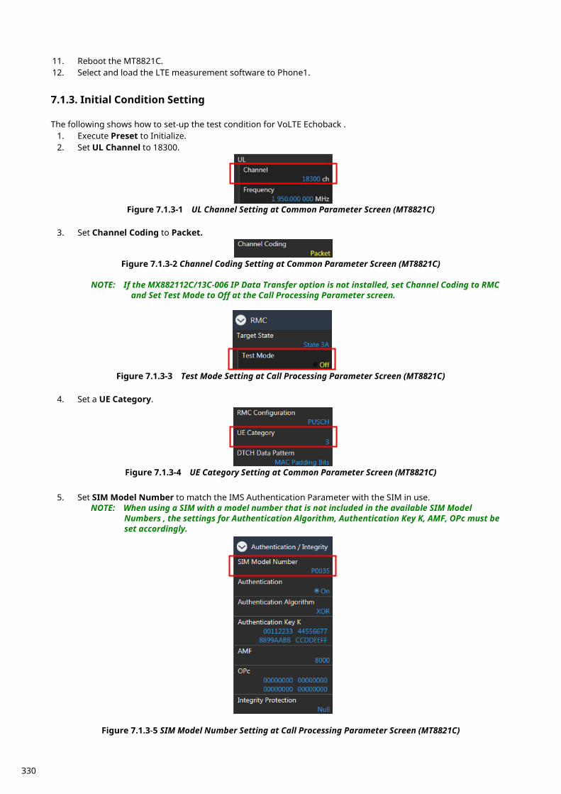
11. Reboot the MT8821C. 12. Select and load the LTE measurement software to Phone1.
Initial Condition Setting 7.1.3. The following shows how to set-up the test condition for VoLTE Echoback .
1. Execute Preset to Initialize. 2. Set UL Channel to 18300.
Figure 7.1.3-1 UL Channel Setting at Common Parameter Screen (MT8821C)
3. Set Channel Coding to Packet.
Figure 7.1.3-2 Channel Coding Setting at Common Parameter Screen (MT8821C) NOTE: If the MX882112C/13C-006 IP Data Transfer option is not installed, set Channel Coding to RMC
and Set Test Mode to Off at the Call Processing Parameter screen.
Figure 7.1.3-3 Test Mode Setting at Call Processing Parameter Screen (MT8821C)
4. Set a UE Category.
Figure 7.1.3-4 UE Category Setting at Common Parameter Screen (MT8821C)
5. Set SIM Model Number to match the IMS Authentication Parameter with the SIM in use. NOTE: When using a SIM with a model number that is not included in the available SIM Model
Numbers , the settings for Authentication Algorithm, Authentication Key K, AMF, OPc must be set accordingly.
Figure 7.1.3-5 SIM Model Number Setting at Call Processing Parameter Screen (MT8821C)
330
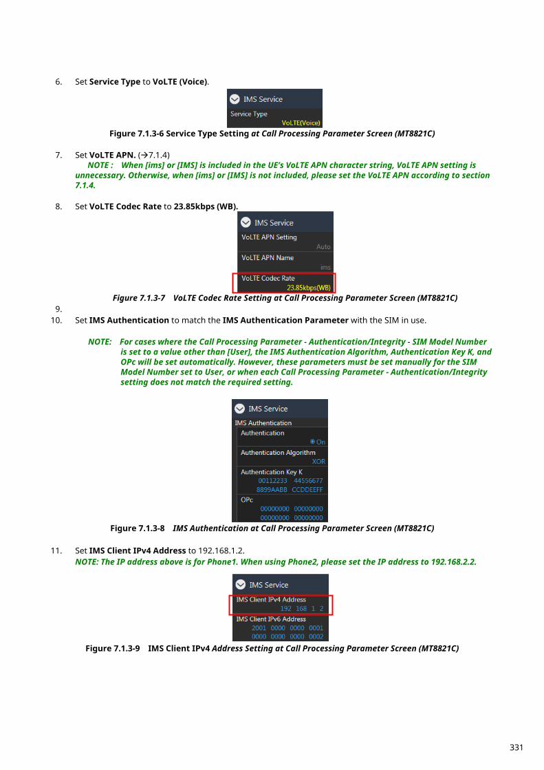
6. Set Service Type to VoLTE (Voice).
Figure 7.1.3-6 Service Type Setting at Call Processing Parameter Screen (MT8821C)
7. Set VoLTE APN. (7.1.4) NOTE : When [ims] or [IMS] is included in the UE’s VoLTE APN character string, VoLTE APN setting is
unnecessary. Otherwise, when [ims] or [IMS] is not included, please set the VoLTE APN according to section 7.1.4.
8. Set VoLTE Codec Rate to 23.85kbps (WB).
Figure 7.1.3-7 VoLTE Codec Rate Setting at Call Processing Parameter Screen (MT8821C)
9. 10. Set IMS Authentication to match the IMS Authentication Parameter with the SIM in use.
NOTE: For cases where the Call Processing Parameter - Authentication/Integrity - SIM Model Number
is set to a value other than [User], the IMS Authentication Algorithm, Authentication Key K, and OPc will be set automatically. However, these parameters must be set manually for the SIM Model Number set to User, or when each Call Processing Parameter - Authentication/Integrity setting does not match the required setting.
Figure 7.1.3-8 IMS Authentication at Call Processing Parameter Screen (MT8821C)
11. Set IMS Client IPv4 Address to 192.168.1.2. NOTE: The IP address above is for Phone1. When using Phone2, please set the IP address to 192.168.2.2.
Figure 7.1.3-9 IMS Client IPv4 Address Setting at Call Processing Parameter Screen (MT8821C)
331
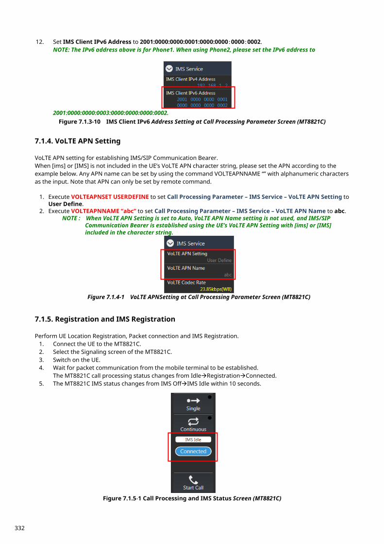
12. Set IMS Client IPv6 Address to 2001:0000:0000:0001:0000:0000:0000:0002. NOTE: The IPv6 address above is for Phone1. When using Phone2, please set the IPv6 address to
2001:0000:0000:0003:0000:0000:0000:0002. Figure 7.1.3-10 IMS Client IPv6 Address Setting at Call Processing Parameter Screen (MT8821C)
VoLTE APN Setting 7.1.4. VoLTE APN setting for establishing IMS/SIP Communication Bearer. When [ims] or [IMS] is not included in the UE’s VoLTE APN character string, please set the APN according to the example below. Any APN name can be set by using the command VOLTEAPNNAME “” with alphanumeric characters as the input. Note that APN can only be set by remote command.
1. Execute VOLTEAPNSET USERDEFINE to set Call Processing Parameter – IMS Service – VoLTE APN Setting to User Define.
2. Execute VOLTEAPNNAME “abc” to set Call Processing Parameter – IMS Service – VoLTE APN Name to abc. NOTE : When VoLTE APN Setting is set to Auto, VoLTE APN Name setting is not used, and IMS/SIP
Communication Bearer is established using the UE’s VoLTE APN Setting with [ims] or [IMS] included in the character string.
Figure 7.1.4-1 VoLTE APNSetting at Call Processing Parameter Screen (MT8821C)
Registration and IMS Registration 7.1.5. Perform UE Location Registration, Packet connection and IMS Registration.
1. Connect the UE to the MT8821C. 2. Select the Signaling screen of the MT8821C. 3. Switch on the UE. 4. Wait for packet communication from the mobile terminal to be established.
The MT8821C call processing status changes from IdleRegistrationConnected. 5. The MT8821C IMS status changes from IMS OffIMS Idle within 10 seconds.
Figure 7.1.5-1 Call Processing and IMS Status Screen (MT8821C)
332
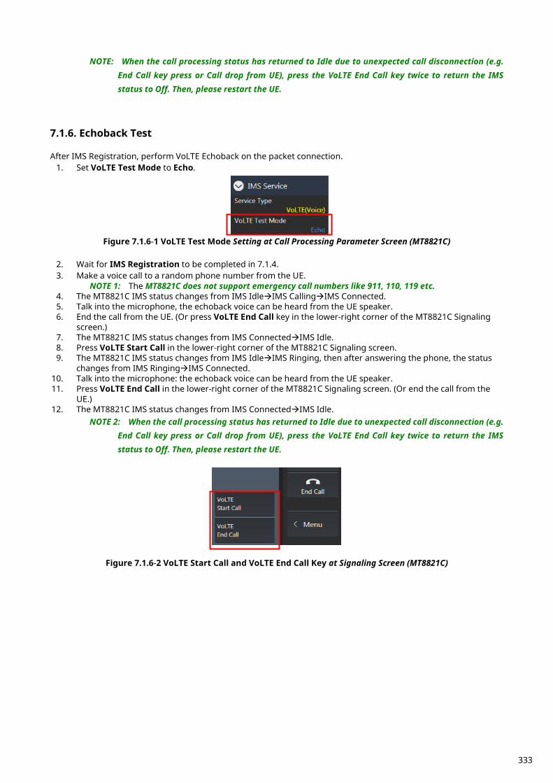
NOTE: When the call processing status has returned to Idle due to unexpected call disconnection (e.g. End Call key press or Call drop from UE), press the VoLTE End Call key twice to return the IMS status to Off. Then, please restart the UE.
Echoback Test 7.1.6. After IMS Registration, perform VoLTE Echoback on the packet connection.
1. Set VoLTE Test Mode to Echo.
Figure 7.1.6-1 VoLTE Test Mode Setting at Call Processing Parameter Screen (MT8821C)
2. Wait for IMS Registration to be completed in 7.1.4. 3. Make a voice call to a random phone number from the UE.
NOTE 1: The MT8821C does not support emergency call numbers like 911, 110, 119 etc. 4. The MT8821C IMS status changes from IMS IdleIMS CallingIMS Connected. 5. Talk into the microphone, the echoback voice can be heard from the UE speaker. 6. End the call from the UE. (Or press VoLTE End Call key in the lower-right corner of the MT8821C Signaling
screen.) 7. The MT8821C IMS status changes from IMS ConnectedIMS Idle. 8. Press VoLTE Start Call in the lower-right corner of the MT8821C Signaling screen. 9. The MT8821C IMS status changes from IMS IdleIMS Ringing, then after answering the phone, the status
changes from IMS RingingIMS Connected. 10. Talk into the microphone: the echoback voice can be heard from the UE speaker. 11. Press VoLTE End Call in the lower-right corner of the MT8821C Signaling screen. (Or end the call from the
UE.) 12. The MT8821C IMS status changes from IMS ConnectedIMS Idle.
NOTE 2: When the call processing status has returned to Idle due to unexpected call disconnection (e.g. End Call key press or Call drop from UE), press the VoLTE End Call key twice to return the IMS status to Off. Then, please restart the UE.
Figure 7.1.6-2 VoLTE Start Call and VoLTE End Call Key at Signaling Screen (MT8821C)
333
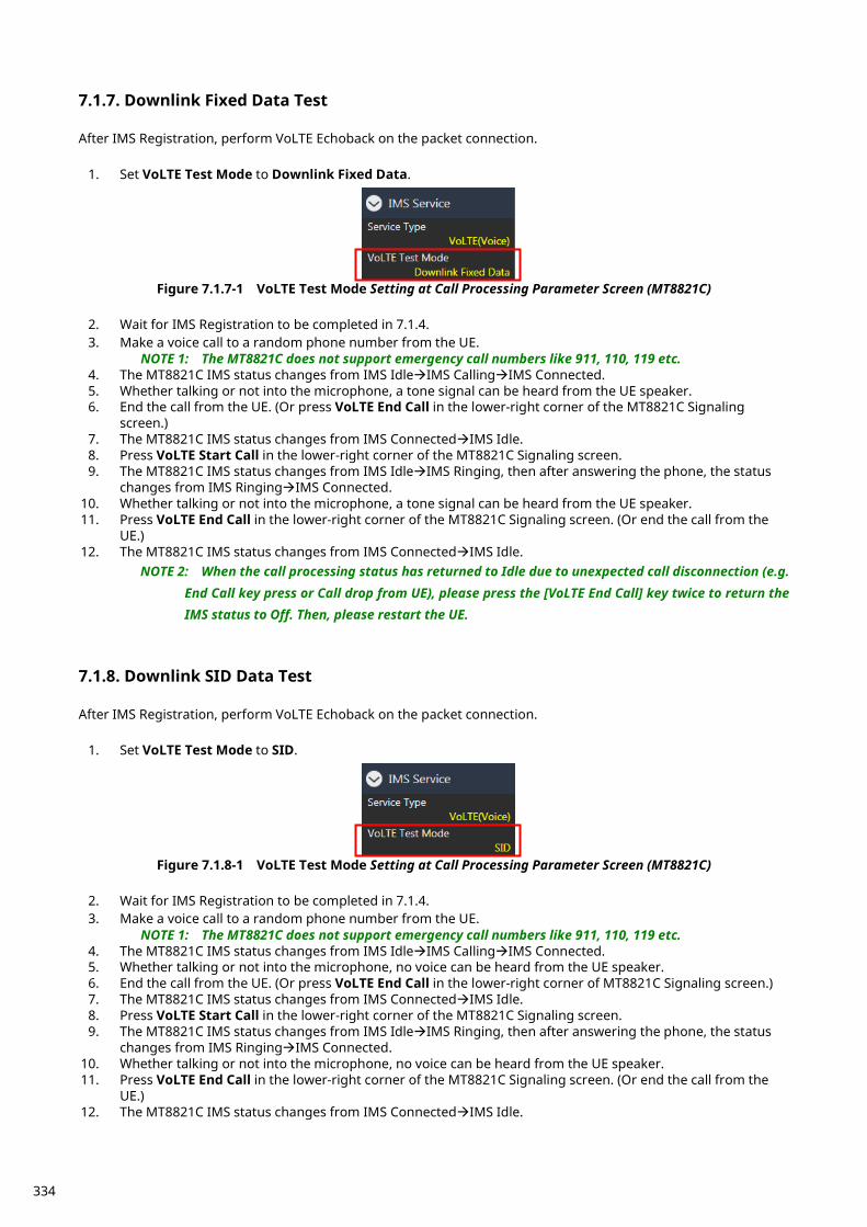
Downlink Fixed Data Test 7.1.7. After IMS Registration, perform VoLTE Echoback on the packet connection.
1. Set VoLTE Test Mode to Downlink Fixed Data.
Figure 7.1.7-1 VoLTE Test Mode Setting at Call Processing Parameter Screen (MT8821C)
2. Wait for IMS Registration to be completed in 7.1.4. 3. Make a voice call to a random phone number from the UE.
NOTE 1: The MT8821C does not support emergency call numbers like 911, 110, 119 etc. 4. The MT8821C IMS status changes from IMS IdleIMS CallingIMS Connected. 5. Whether talking or not into the microphone, a tone signal can be heard from the UE speaker. 6. End the call from the UE. (Or press VoLTE End Call in the lower-right corner of the MT8821C Signaling
screen.) 7. The MT8821C IMS status changes from IMS ConnectedIMS Idle. 8. Press VoLTE Start Call in the lower-right corner of the MT8821C Signaling screen. 9. The MT8821C IMS status changes from IMS IdleIMS Ringing, then after answering the phone, the status
changes from IMS RingingIMS Connected. 10. Whether talking or not into the microphone, a tone signal can be heard from the UE speaker. 11. Press VoLTE End Call in the lower-right corner of the MT8821C Signaling screen. (Or end the call from the
UE.) 12. The MT8821C IMS status changes from IMS ConnectedIMS Idle.
NOTE 2: When the call processing status has returned to Idle due to unexpected call disconnection (e.g. End Call key press or Call drop from UE), please press the [VoLTE End Call] key twice to return the IMS status to Off. Then, please restart the UE.
Downlink SID Data Test 7.1.8. After IMS Registration, perform VoLTE Echoback on the packet connection.
1. Set VoLTE Test Mode to SID.
Figure 7.1.8-1 VoLTE Test Mode Setting at Call Processing Parameter Screen (MT8821C)
2. Wait for IMS Registration to be completed in 7.1.4. 3. Make a voice call to a random phone number from the UE.
NOTE 1: The MT8821C does not support emergency call numbers like 911, 110, 119 etc. 4. The MT8821C IMS status changes from IMS IdleIMS CallingIMS Connected. 5. Whether talking or not into the microphone, no voice can be heard from the UE speaker. 6. End the call from the UE. (Or press VoLTE End Call in the lower-right corner of MT8821C Signaling screen.) 7. The MT8821C IMS status changes from IMS ConnectedIMS Idle. 8. Press VoLTE Start Call in the lower-right corner of the MT8821C Signaling screen. 9. The MT8821C IMS status changes from IMS IdleIMS Ringing, then after answering the phone, the status
changes from IMS RingingIMS Connected. 10. Whether talking or not into the microphone, no voice can be heard from the UE speaker. 11. Press VoLTE End Call in the lower-right corner of the MT8821C Signaling screen. (Or end the call from the
UE.) 12. The MT8821C IMS status changes from IMS ConnectedIMS Idle.
334

NOTE 2: When the call processing status has returned to Idle due to unexpected call disconnection (e.g. End Call key press or Call drop from UE), please press the VoLTE End Call key twice to return the IMS status to Off. Then, restart the UE.
335
SMS Test (MT8821C Only) 8.
MT8821C UE SMS send 8.1.This is an example of sending an SMS from the MT8821C to the UE. Input alphanumeric characters at SENDSMS_USER “”. The character limit is 160 max. The connection to the UE is the same procedure as described in 2.1.1 Connection Diagram to 2.1.4 Test Mode Connection and Disconnection.
Send SMS 8.1.1. 1. Execute CALLSTATIC? to confirm the call processing stationary status is 6 ( Connected). 2. Execute SENDSMS_USER “Hello world” to send an SMS from MT8821C to the UE. 3. Confirm that the UE successfully received the SMS “Hello world”
UE MT8821C SMS receive 8.2.This is an example of receiving an SMS sent from the UE to the MT8821C. The MT8821C receives the SMS from the UE, and the user confirms the message from the query result. The connection to the UE uses the same procedure as described in 2.1.1 Connection Diagram to 2.1.4 Test Mode Connection and Disconnection.
Receive SMS 8.2.1. 1. Execute SMS_MSG? FLAG to confirm the SMS reception flag is 0 (unreceived). 2. Send the SMS message “Hello world” from the UE. 3. Execute SMS_MSG? FLAG to confirm the SMS reception flag is 1 (received). 4. Execute SMS_MSG? to confirm the query result is “Hello world”.
Clear SMS 8.2.2. 1. To clear the received SMS, execute SMSCLR. 2. Execute SMS_MSG? FLAG to confirm the SMS reception flag is 0 (unreceived). 3. Execute SMS_MSG? to confirm the query result is “-” (Initial value). 4. The SMS reception test can be continued by following the procedure described in 8.2.1.
336
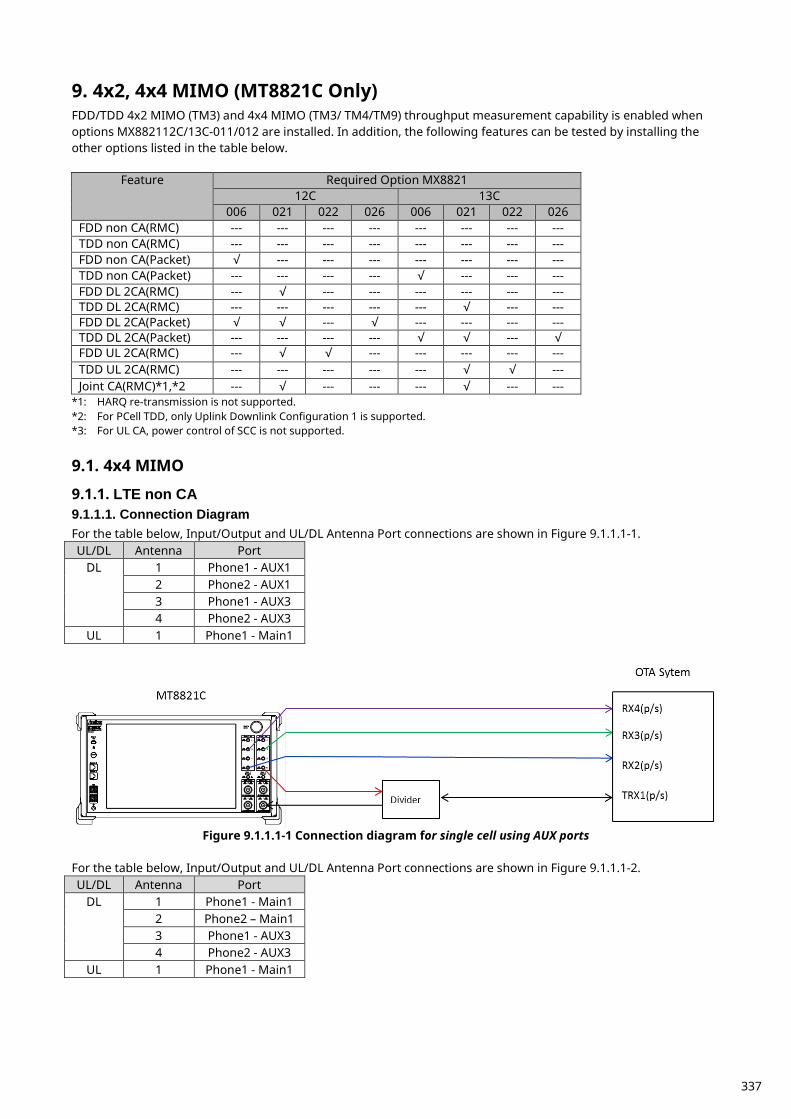
4x2, 4x4 MIMO (MT8821C Only) 9.FDD/TDD 4x2 MIMO (TM3) and 4x4 MIMO (TM3/ TM4/TM9) throughput measurement capability is enabled when options MX882112C/13C-011/012 are installed. In addition, the following features can be tested by installing the other options listed in the table below.
Feature Required Option MX8821 12C 13C
006 021 022 026 006 021 022 026 FDD non CA(RMC) --- --- --- --- --- --- --- --- TDD non CA(RMC) --- --- --- --- --- --- --- --- FDD non CA(Packet) √ --- --- --- --- --- --- --- TDD non CA(Packet) --- --- --- --- √ --- --- --- FDD DL 2CA(RMC) --- √ --- --- --- --- --- --- TDD DL 2CA(RMC) --- --- --- --- --- √ --- --- FDD DL 2CA(Packet) √ √ --- √ --- --- --- --- TDD DL 2CA(Packet) --- --- --- --- √ √ --- √ FDD UL 2CA(RMC) --- √ √ --- --- --- --- --- TDD UL 2CA(RMC) --- --- --- --- --- √ √ --- Joint CA(RMC)*1,*2 --- √ --- --- --- √ --- ---
*1: HARQ re-transmission is not supported. *2: For PCell TDD, only Uplink Downlink Configuration 1 is supported. *3: For UL CA, power control of SCC is not supported.
4x4 MIMO 9.1.
LTE non CA 9.1.1.9.1.1.1. Connection Diagram For the table below, Input/Output and UL/DL Antenna Port connections are shown in Figure 9.1.1.1-1. UL/DL Antenna Port
DL 1 Phone1 - AUX1 2 Phone2 - AUX1 3 Phone1 - AUX3 4 Phone2 - AUX3
UL 1 Phone1 - Main1
Figure 9.1.1.1-1 Connection diagram for single cell using AUX ports
For the table below, Input/Output and UL/DL Antenna Port connections are shown in Figure 9.1.1.1-2. UL/DL Antenna Port
DL 1 Phone1 - Main1 2 Phone2 – Main1 3 Phone1 - AUX3 4 Phone2 - AUX3
UL 1 Phone1 - Main1
337
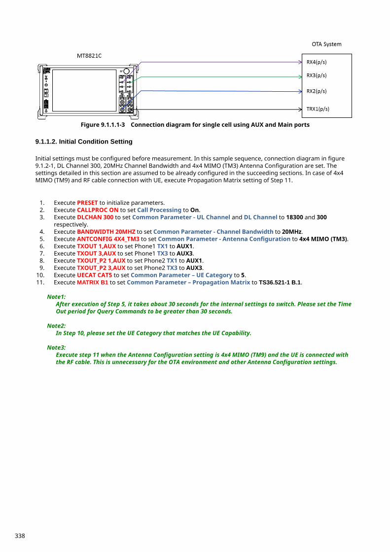
Figure 9.1.1.1-3 Connection diagram for single cell using AUX and Main ports
9.1.1.2. Initial Condition Setting Initial settings must be configured before measurement. In this sample sequence, connection diagram in figure 9.1.2-1, DL Channel 300, 20MHz Channel Bandwidth and 4x4 MIMO (TM3) Antenna Configuration are set. The settings detailed in this section are assumed to be already configured in the succeeding sections. In case of 4x4 MIMO (TM9) and RF cable connection with UE, execute Propagation Matrix setting of Step 11.
1. Execute PRESET to initialize parameters. 2. Execute CALLPROC ON to set Call Processing to On. 3. Execute DLCHAN 300 to set Common Parameter - UL Channel and DL Channel to 18300 and 300
respectively. 4. Execute BANDWIDTH 20MHZ to set Common Parameter - Channel Bandwidth to 20MHz. 5. Execute ANTCONFIG 4X4_TM3 to set Common Parameter - Antenna Configuration to 4x4 MIMO (TM3). 6. Execute TXOUT 1,AUX to set Phone1 TX1 to AUX1. 7. Execute TXOUT 3,AUX to set Phone1 TX3 to AUX3. 8. Execute TXOUT_P2 1,AUX to set Phone2 TX1 to AUX1. 9. Execute TXOUT_P2 3,AUX to set Phone2 TX3 to AUX3.
10. Execute UECAT CAT5 to set Common Parameter – UE Category to 5. 11. Execute MATRIX B1 to set Common Parameter – Propagation Matrix to TS36.521-1 B.1.
Note1:
After execution of Step 5, it takes about 30 seconds for the internal settings to switch. Please set the Time Out period for Query Commands to be greater than 30 seconds.
Note2: In Step 10, please set the UE Category that matches the UE Capability.
Note3: Execute step 11 when the Antenna Configuration setting is 4x4 MIMO (TM9) and the UE is connected with the RF cable. This is unnecessary for the OTA environment and other Antenna Configuration settings.
338
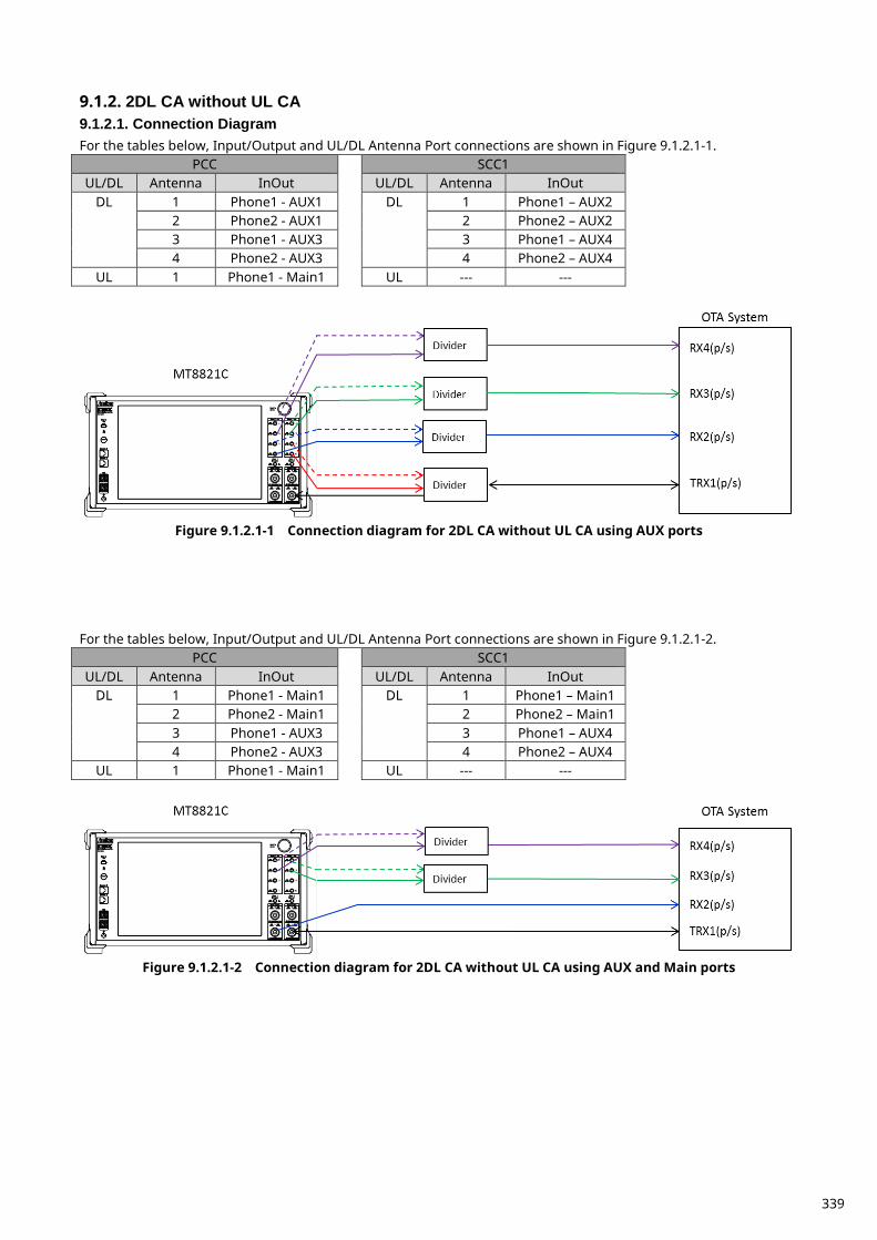
2DL CA without UL CA 9.1.2.9.1.2.1. Connection Diagram For the tables below, Input/Output and UL/DL Antenna Port connections are shown in Figure 9.1.2.1-1.
PCC SCC1 UL/DL Antenna InOut UL/DL Antenna InOut
DL 1 Phone1 - AUX1 DL 1 Phone1 – AUX2 2 Phone2 - AUX1 2 Phone2 – AUX2 3 Phone1 - AUX3 3 Phone1 – AUX4 4 Phone2 - AUX3 4 Phone2 – AUX4
UL 1 Phone1 - Main1 UL --- ---
Figure 9.1.2.1-1 Connection diagram for 2DL CA without UL CA using AUX ports
For the tables below, Input/Output and UL/DL Antenna Port connections are shown in Figure 9.1.2.1-2.
PCC SCC1 UL/DL Antenna InOut UL/DL Antenna InOut
DL 1 Phone1 - Main1 DL 1 Phone1 – Main1 2 Phone2 - Main1 2 Phone2 – Main1 3 Phone1 - AUX3 3 Phone1 – AUX4 4 Phone2 - AUX3 4 Phone2 – AUX4
UL 1 Phone1 - Main1 UL --- ---
Figure 9.1.2.1-2 Connection diagram for 2DL CA without UL CA using AUX and Main ports
339
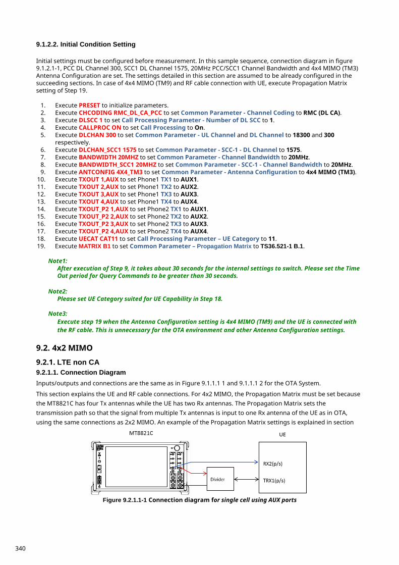
9.1.2.2. Initial Condition Setting Initial settings must be configured before measurement. In this sample sequence, connection diagram in figure 9.1.2.1-1, PCC DL Channel 300, SCC1 DL Channel 1575, 20MHz PCC/SCC1 Channel Bandwidth and 4x4 MIMO (TM3) Antenna Configuration are set. The settings detailed in this section are assumed to be already configured in the succeeding sections. In case of 4x4 MIMO (TM9) and RF cable connection with UE, execute Propagation Matrix setting of Step 19.
1. Execute PRESET to initialize parameters. 2. Execute CHCODING RMC_DL_CA_PCC to set Common Parameter - Channel Coding to RMC (DL CA). 3. Execute DLSCC 1 to set Call Processing Parameter - Number of DL SCC to 1. 4. Execute CALLPROC ON to set Call Processing to On. 5. Execute DLCHAN 300 to set Common Parameter - UL Channel and DL Channel to 18300 and 300
respectively. 6. Execute DLCHAN_SCC1 1575 to set Common Parameter - SCC-1 - DL Channel to 1575. 7. Execute BANDWIDTH 20MHZ to set Common Parameter - Channel Bandwidth to 20MHz. 8. Execute BANDWIDTH_SCC1 20MHZ to set Common Parameter - SCC-1 - Channel Bandwidth to 20MHz. 9. Execute ANTCONFIG 4X4_TM3 to set Common Parameter - Antenna Configuration to 4x4 MIMO (TM3).
10. Execute TXOUT 1,AUX to set Phone1 TX1 to AUX1. 11. Execute TXOUT 2,AUX to set Phone1 TX2 to AUX2. 12. Execute TXOUT 3,AUX to set Phone1 TX3 to AUX3. 13. Execute TXOUT 4,AUX to set Phone1 TX4 to AUX4. 14. Execute TXOUT_P2 1,AUX to set Phone2 TX1 to AUX1. 15. Execute TXOUT_P2 2,AUX to set Phone2 TX2 to AUX2. 16. Execute TXOUT_P2 3,AUX to set Phone2 TX3 to AUX3. 17. Execute TXOUT_P2 4,AUX to set Phone2 TX4 to AUX4. 18. Execute UECAT CAT11 to set Call Processing Parameter – UE Category to 11. 19. Execute MATRIX B1 to set Common Parameter – Propagation Matrix to TS36.521-1 B.1.
Note1:
After execution of Step 9, it takes about 30 seconds for the internal settings to switch. Please set the Time Out period for Query Commands to be greater than 30 seconds.
Note2:
Please set UE Category suited for UE Capability in Step 18.
Note3: Execute step 19 when the Antenna Configuration setting is 4x4 MIMO (TM9) and the UE is connected with the RF cable. This is unnecessary for the OTA environment and other Antenna Configuration settings.
4x2 MIMO 9.2.
LTE non CA 9.2.1.9.2.1.1. Connection Diagram Inputs/outputs and connections are the same as in Figure 9.1.1.1 1 and 9.1.1.1 2 for the OTA System.
This section explains the UE and RF cable connections. For 4x2 MIMO, the Propagation Matrix must be set because the MT8821C has four Tx antennas while the UE has two Rx antennas. The Propagation Matrix sets the transmission path so that the signal from multiple Tx antennas is input to one Rx antenna of the UE as in OTA, using the same connections as 2x2 MIMO. An example of the Propagation Matrix settings is explained in section
Figure 9.2.1.1-1 Connection diagram for single cell using AUX ports
340
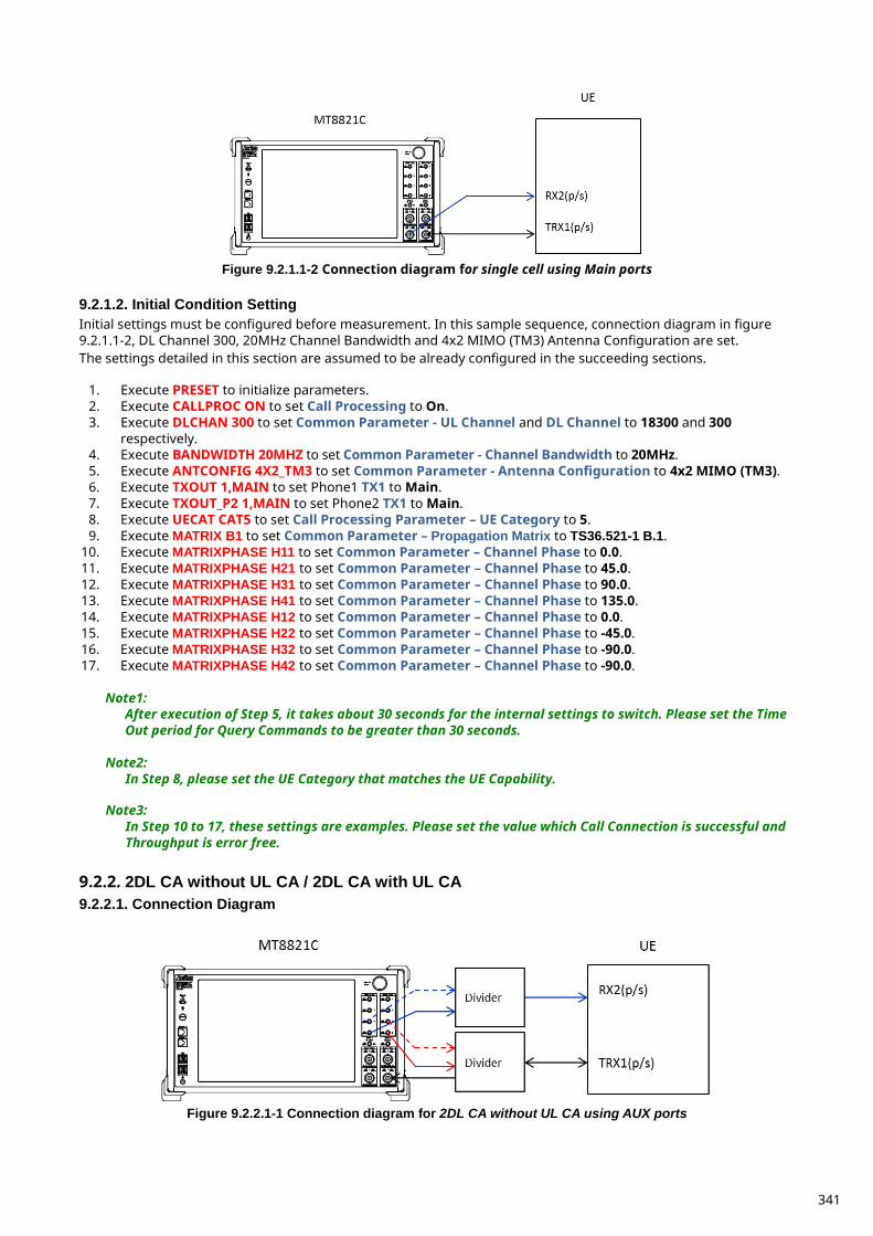
Figure 9.2.1.1-2 Connection diagram for single cell using Main ports
9.2.1.2. Initial Condition Setting Initial settings must be configured before measurement. In this sample sequence, connection diagram in figure 9.2.1.1-2, DL Channel 300, 20MHz Channel Bandwidth and 4x2 MIMO (TM3) Antenna Configuration are set. The settings detailed in this section are assumed to be already configured in the succeeding sections.
1. Execute PRESET to initialize parameters. 2. Execute CALLPROC ON to set Call Processing to On. 3. Execute DLCHAN 300 to set Common Parameter - UL Channel and DL Channel to 18300 and 300
respectively. 4. Execute BANDWIDTH 20MHZ to set Common Parameter - Channel Bandwidth to 20MHz. 5. Execute ANTCONFIG 4X2_TM3 to set Common Parameter - Antenna Configuration to 4x2 MIMO (TM3). 6. Execute TXOUT 1,MAIN to set Phone1 TX1 to Main. 7. Execute TXOUT_P2 1,MAIN to set Phone2 TX1 to Main. 8. Execute UECAT CAT5 to set Call Processing Parameter – UE Category to 5. 9. Execute MATRIX B1 to set Common Parameter – Propagation Matrix to TS36.521-1 B.1.
10. Execute MATRIXPHASE H11 to set Common Parameter – Channel Phase to 0.0. 11. Execute MATRIXPHASE H21 to set Common Parameter – Channel Phase to 45.0. 12. Execute MATRIXPHASE H31 to set Common Parameter – Channel Phase to 90.0. 13. Execute MATRIXPHASE H41 to set Common Parameter – Channel Phase to 135.0. 14. Execute MATRIXPHASE H12 to set Common Parameter – Channel Phase to 0.0. 15. Execute MATRIXPHASE H22 to set Common Parameter – Channel Phase to -45.0. 16. Execute MATRIXPHASE H32 to set Common Parameter – Channel Phase to -90.0. 17. Execute MATRIXPHASE H42 to set Common Parameter – Channel Phase to -90.0.
Note1:
After execution of Step 5, it takes about 30 seconds for the internal settings to switch. Please set the Time Out period for Query Commands to be greater than 30 seconds.
Note2: In Step 8, please set the UE Category that matches the UE Capability.
Note3:
In Step 10 to 17, these settings are examples. Please set the value which Call Connection is successful and Throughput is error free.
2DL CA without UL CA / 2DL CA with UL CA 9.2.2.9.2.2.1. Connection Diagram
Figure 9.2.2.1-1 Connection diagram for 2DL CA without UL CA using AUX ports
341
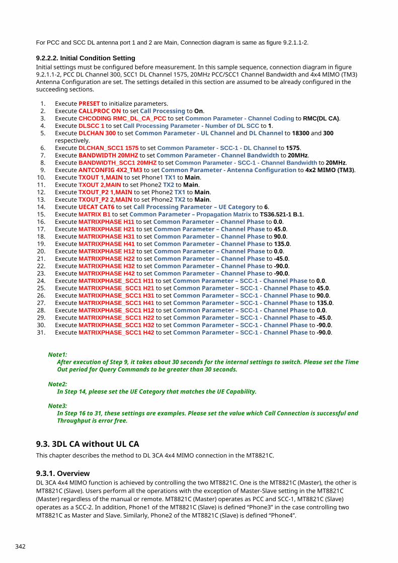
For PCC and SCC DL antenna port 1 and 2 are Main, Connection diagram is same as figure 9.2.1.1-2.
9.2.2.2. Initial Condition Setting Initial settings must be configured before measurement. In this sample sequence, connection diagram in figure 9.2.1.1-2, PCC DL Channel 300, SCC1 DL Channel 1575, 20MHz PCC/SCC1 Channel Bandwidth and 4x4 MIMO (TM3) Antenna Configuration are set. The settings detailed in this section are assumed to be already configured in the succeeding sections.
1. Execute PRESET to initialize parameters. 2. Execute CALLPROC ON to set Call Processing to On. 3. Execute CHCODING RMC_DL_CA_PCC to set Common Parameter - Channel Coding to RMC(DL CA). 4. Execute DLSCC 1 to set Call Processing Parameter - Number of DL SCC to 1. 5. Execute DLCHAN 300 to set Common Parameter - UL Channel and DL Channel to 18300 and 300
respectively. 6. Execute DLCHAN_SCC1 1575 to set Common Parameter - SCC-1 - DL Channel to 1575. 7. Execute BANDWIDTH 20MHZ to set Common Parameter - Channel Bandwidth to 20MHz. 8. Execute BANDWIDTH_SCC1 20MHZ to set Common Parameter - SCC-1 - Channel Bandwidth to 20MHz. 9. Execute ANTCONFIG 4X2_TM3 to set Common Parameter - Antenna Configuration to 4x2 MIMO (TM3).
10. Execute TXOUT 1,MAIN to set Phone1 TX1 to Main. 11. Execute TXOUT 2,MAIN to set Phone2 TX2 to Main. 12. Execute TXOUT_P2 1,MAIN to set Phone2 TX1 to Main. 13. Execute TXOUT_P2 2,MAIN to set Phone2 TX2 to Main. 14. Execute UECAT CAT6 to set Call Processing Parameter – UE Category to 6. 15. Execute MATRIX B1 to set Common Parameter – Propagation Matrix to TS36.521-1 B.1. 16. Execute MATRIXPHASE H11 to set Common Parameter – Channel Phase to 0.0. 17. Execute MATRIXPHASE H21 to set Common Parameter – Channel Phase to 45.0. 18. Execute MATRIXPHASE H31 to set Common Parameter – Channel Phase to 90.0. 19. Execute MATRIXPHASE H41 to set Common Parameter – Channel Phase to 135.0. 20. Execute MATRIXPHASE H12 to set Common Parameter – Channel Phase to 0.0. 21. Execute MATRIXPHASE H22 to set Common Parameter – Channel Phase to -45.0. 22. Execute MATRIXPHASE H32 to set Common Parameter – Channel Phase to -90.0. 23. Execute MATRIXPHASE H42 to set Common Parameter – Channel Phase to -90.0. 24. Execute MATRIXPHASE_SCC1 H11 to set Common Parameter – SCC-1 - Channel Phase to 0.0. 25. Execute MATRIXPHASE_SCC1 H21 to set Common Parameter – SCC-1 - Channel Phase to 45.0. 26. Execute MATRIXPHASE_SCC1 H31 to set Common Parameter – SCC-1 - Channel Phase to 90.0. 27. Execute MATRIXPHASE_SCC1 H41 to set Common Parameter – SCC-1 - Channel Phase to 135.0. 28. Execute MATRIXPHASE_SCC1 H12 to set Common Parameter – SCC-1 - Channel Phase to 0.0. 29. Execute MATRIXPHASE_SCC1 H22 to set Common Parameter – SCC-1 - Channel Phase to -45.0. 30. Execute MATRIXPHASE_SCC1 H32 to set Common Parameter – SCC-1 - Channel Phase to -90.0. 31. Execute MATRIXPHASE_SCC1 H42 to set Common Parameter – SCC-1 - Channel Phase to -90.0.
Note1:
After execution of Step 9, it takes about 30 seconds for the internal settings to switch. Please set the Time Out period for Query Commands to be greater than 30 seconds.
Note2: In Step 14, please set the UE Category that matches the UE Capability.
Note3:
In Step 16 to 31, these settings are examples. Please set the value which Call Connection is successful and Throughput is error free.
3DL CA without UL CA 9.3.This chapter describes the method to DL 3CA 4x4 MIMO connection in the MT8821C.
Overview 9.3.1.DL 3CA 4x4 MIMO function is achieved by controlling the two MT8821C. One is the MT8821C (Master), the other is MT8821C (Slave). Users perform all the operations with the exception of Master-Slave setting in the MT8821C (Master) regardless of the manual or remote. MT8821C (Master) operates as PCC and SCC-1, MT8821C (Slave) operates as a SCC-2. In addition, Phone1 of the MT8821C (Slave) is defined “Phone3” in the case controlling two MT8821C as Master and Slave. Similarly, Phone2 of the MT8821C (Slave) is defined “Phone4”.
342
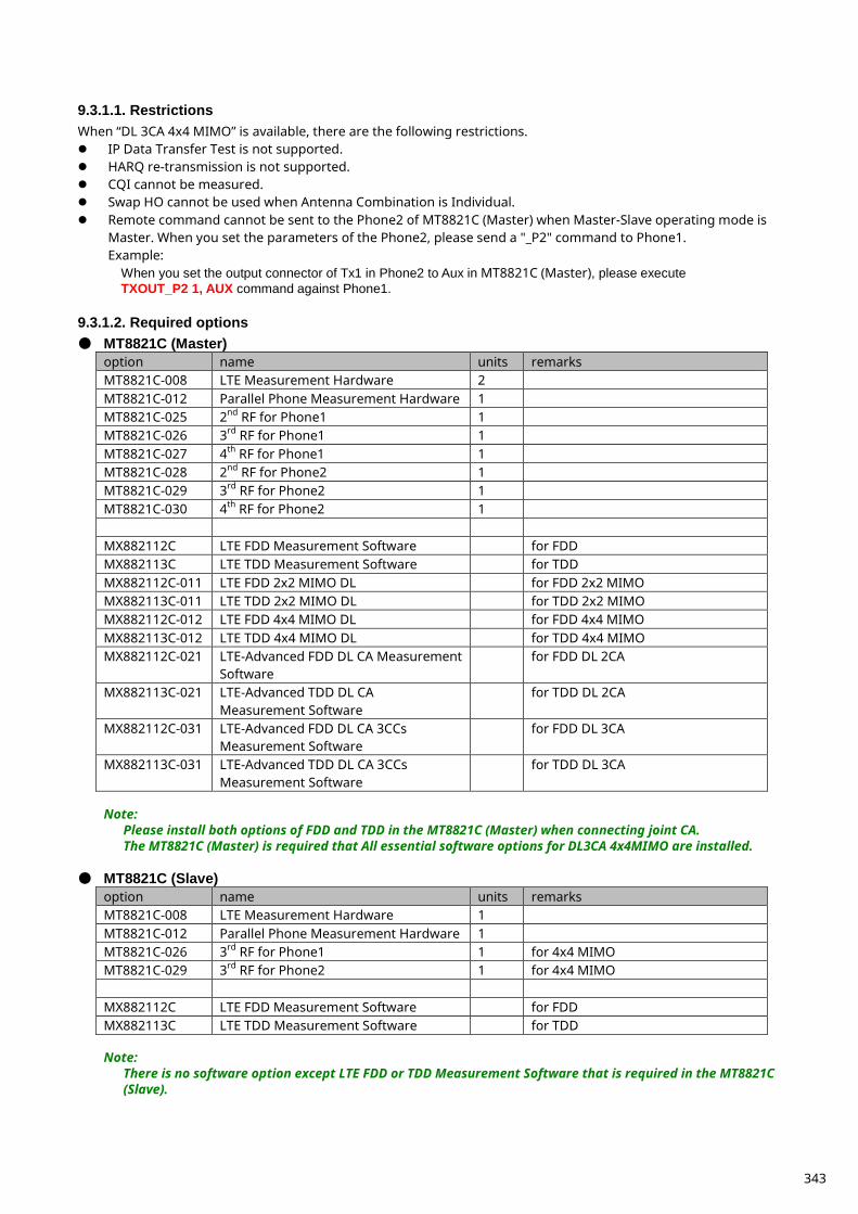
9.3.1.1. Restrictions When “DL 3CA 4x4 MIMO” is available, there are the following restrictions. IP Data Transfer Test is not supported. HARQ re-transmission is not supported. CQI cannot be measured. Swap HO cannot be used when Antenna Combination is Individual. Remote command cannot be sent to the Phone2 of MT8821C (Master) when Master-Slave operating mode is
Master. When you set the parameters of the Phone2, please send a "_P2" command to Phone1. Example:
When you set the output connector of Tx1 in Phone2 to Aux in MT8821C (Master), please execute TXOUT_P2 1, AUX command against Phone1.
9.3.1.2. Required options ● MT8821C (Master)
option name units remarks MT8821C-008 LTE Measurement Hardware 2 MT8821C-012 Parallel Phone Measurement Hardware 1 MT8821C-025 2nd RF for Phone1 1 MT8821C-026 3rd RF for Phone1 1 MT8821C-027 4th RF for Phone1 1 MT8821C-028 2nd RF for Phone2 1 MT8821C-029 3rd RF for Phone2 1 MT8821C-030 4th RF for Phone2 1 MX882112C LTE FDD Measurement Software for FDD MX882113C LTE TDD Measurement Software for TDD MX882112C-011 LTE FDD 2x2 MIMO DL for FDD 2x2 MIMO MX882113C-011 LTE TDD 2x2 MIMO DL for TDD 2x2 MIMO MX882112C-012 LTE FDD 4x4 MIMO DL for FDD 4x4 MIMO MX882113C-012 LTE TDD 4x4 MIMO DL for TDD 4x4 MIMO MX882112C-021 LTE-Advanced FDD DL CA Measurement
Software for FDD DL 2CA
MX882113C-021 LTE-Advanced TDD DL CA Measurement Software
for TDD DL 2CA
MX882112C-031 LTE-Advanced FDD DL CA 3CCs Measurement Software
for FDD DL 3CA
MX882113C-031 LTE-Advanced TDD DL CA 3CCs Measurement Software
for TDD DL 3CA
Note:
Please install both options of FDD and TDD in the MT8821C (Master) when connecting joint CA. The MT8821C (Master) is required that All essential software options for DL3CA 4x4MIMO are installed.
● MT8821C (Slave)
option name units remarks MT8821C-008 LTE Measurement Hardware 1 MT8821C-012 Parallel Phone Measurement Hardware 1 MT8821C-026 3rd RF for Phone1 1 for 4x4 MIMO MT8821C-029 3rd RF for Phone2 1 for 4x4 MIMO MX882112C LTE FDD Measurement Software for FDD MX882113C LTE TDD Measurement Software for TDD
Note:
There is no software option except LTE FDD or TDD Measurement Software that is required in the MT8821C (Slave).
343
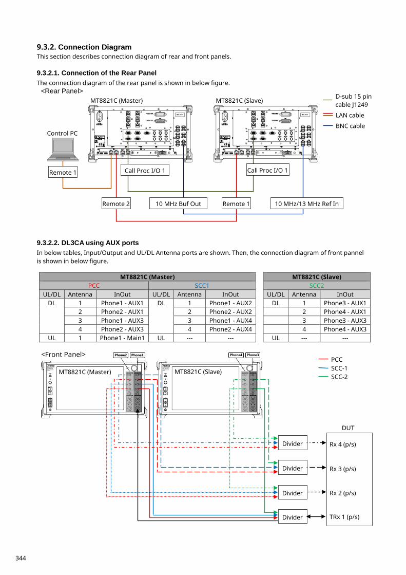
Connection Diagram 9.3.2.This section describes connection diagram of rear and front panels. 9.3.2.1. Connection of the Rear Panel The connection diagram of the rear panel is shown in below figure.
9.3.2.2. DL3CA using AUX ports In below tables, Input/Output and UL/DL Antenna ports are shown. Then, the connection diagram of front pannel is shown in below figure.
MT8821C (Master) MT8821C (Slave) PCC SCC1 SCC2
UL/DL Antenna InOut UL/DL Antenna InOut UL/DL Antenna InOut DL 1 Phone1 - AUX1 DL 1 Phone1 - AUX2 DL 1 Phone3 - AUX1
2 Phone2 - AUX1 2 Phone2 - AUX2 2 Phone4 - AUX1 3 Phone1 - AUX3 3 Phone1 - AUX4 3 Phone3 - AUX3 4 Phone2 - AUX3 4 Phone2 - AUX4 4 Phone4 - AUX3
UL 1 Phone1 - Main1 UL --- --- UL --- ---
MT8821C (Master) MT8821C (Slave)
Control PC
Remote 1 Call Proc I/O 1 Call Proc I/O 1
Remote 2 Remote 1 10 MHz Buf Out 10 MHz/13 MHz Ref In
<Rear Panel> D-sub 15 pin cable J1249
LAN cable
BNC cable
Rx 4 (p/s)
Rx 3 (p/s)
Rx 2 (p/s)
TRx 1 (p/s)
DUT
Divider
Divider
Divider
Divider
MT8821C (Master) MT8821C (Slave)
<Front Panel> Phone1 Phone2 Phone3 Phone4
SCC-1 SCC-2
PCC
344
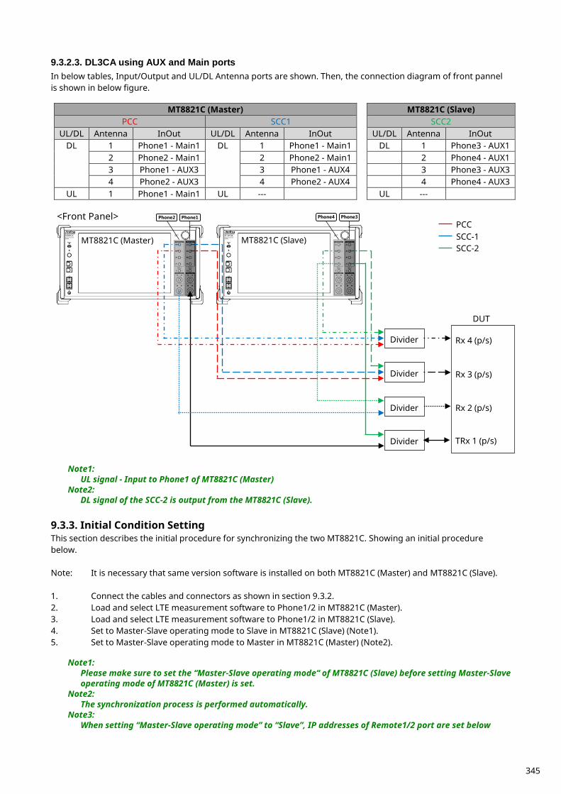
9.3.2.3. DL3CA using AUX and Main ports In below tables, Input/Output and UL/DL Antenna ports are shown. Then, the connection diagram of front pannel is shown in below figure.
MT8821C (Master) MT8821C (Slave) PCC SCC1 SCC2
UL/DL Antenna InOut UL/DL Antenna InOut UL/DL Antenna InOut DL 1 Phone1 - Main1 DL 1 Phone1 - Main1 DL 1 Phone3 - AUX1
2 Phone2 - Main1 2 Phone2 - Main1 2 Phone4 - AUX1 3 Phone1 - AUX3 3 Phone1 - AUX4 3 Phone3 - AUX3 4 Phone2 - AUX3 4 Phone2 - AUX4 4 Phone4 - AUX3
UL 1 Phone1 - Main1 UL --- UL ---
Note1: UL signal - Input to Phone1 of MT8821C (Master)
Note2: DL signal of the SCC-2 is output from the MT8821C (Slave).
Initial Condition Setting 9.3.3.This section describes the initial procedure for synchronizing the two MT8821C. Showing an initial procedure below. Note: It is necessary that same version software is installed on both MT8821C (Master) and MT8821C (Slave). 1. Connect the cables and connectors as shown in section 9.3.2. 2. Load and select LTE measurement software to Phone1/2 in MT8821C (Master). 3. Load and select LTE measurement software to Phone1/2 in MT8821C (Slave). 4. Set to Master-Slave operating mode to Slave in MT8821C (Slave) (Note1). 5. Set to Master-Slave operating mode to Master in MT8821C (Master) (Note2).
Note1: Please make sure to set the “Master-Slave operating mode“ of MT8821C (Slave) before setting Master-Slave operating mode of MT8821C (Master) is set.
Note2: The synchronization process is performed automatically.
Note3: When setting “Master-Slave operating mode” to “Slave”, IP addresses of Remote1/2 port are set below
Rx 4 (p/s)
Rx 3 (p/s)
Rx 2 (p/s)
TRx 1 (p/s)
DUT
Divider
Divider
Divider
Divider
MT8821C (Master) MT8821C (Slave)
<Front Panel> Phone1 Phone2 Phone3 Phone4
SCC-1 SCC-2
PCC
345
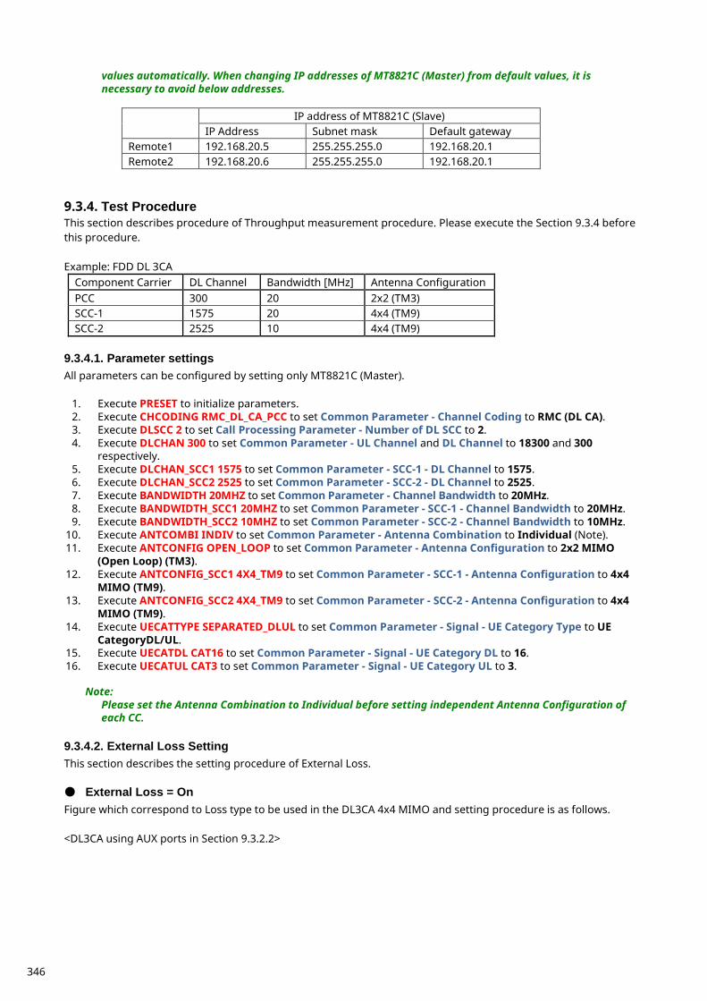
values automatically. When changing IP addresses of MT8821C (Master) from default values, it is necessary to avoid below addresses.
IP address of MT8821C (Slave)
IP Address Subnet mask Default gateway Remote1 192.168.20.5 255.255.255.0 192.168.20.1 Remote2 192.168.20.6 255.255.255.0 192.168.20.1
Test Procedure 9.3.4.This section describes procedure of Throughput measurement procedure. Please execute the Section 9.3.4 before this procedure. Example: FDD DL 3CA
Component Carrier DL Channel Bandwidth [MHz] Antenna Configuration PCC 300 20 2x2 (TM3) SCC-1 1575 20 4x4 (TM9) SCC-2 2525 10 4x4 (TM9)
9.3.4.1. Parameter settings All parameters can be configured by setting only MT8821C (Master).
1. Execute PRESET to initialize parameters. 2. Execute CHCODING RMC_DL_CA_PCC to set Common Parameter - Channel Coding to RMC (DL CA). 3. Execute DLSCC 2 to set Call Processing Parameter - Number of DL SCC to 2. 4. Execute DLCHAN 300 to set Common Parameter - UL Channel and DL Channel to 18300 and 300
respectively. 5. Execute DLCHAN_SCC1 1575 to set Common Parameter - SCC-1 - DL Channel to 1575. 6. Execute DLCHAN_SCC2 2525 to set Common Parameter - SCC-2 - DL Channel to 2525. 7. Execute BANDWIDTH 20MHZ to set Common Parameter - Channel Bandwidth to 20MHz. 8. Execute BANDWIDTH_SCC1 20MHZ to set Common Parameter - SCC-1 - Channel Bandwidth to 20MHz. 9. Execute BANDWIDTH_SCC2 10MHZ to set Common Parameter - SCC-2 - Channel Bandwidth to 10MHz.
10. Execute ANTCOMBI INDIV to set Common Parameter - Antenna Combination to Individual (Note). 11. Execute ANTCONFIG OPEN_LOOP to set Common Parameter - Antenna Configuration to 2x2 MIMO
(Open Loop) (TM3). 12. Execute ANTCONFIG_SCC1 4X4_TM9 to set Common Parameter - SCC-1 - Antenna Configuration to 4x4
MIMO (TM9). 13. Execute ANTCONFIG_SCC2 4X4_TM9 to set Common Parameter - SCC-2 - Antenna Configuration to 4x4
MIMO (TM9). 14. Execute UECATTYPE SEPARATED_DLUL to set Common Parameter - Signal - UE Category Type to UE
CategoryDL/UL. 15. Execute UECATDL CAT16 to set Common Parameter - Signal - UE Category DL to 16. 16. Execute UECATUL CAT3 to set Common Parameter - Signal - UE Category UL to 3.
Note: Please set the Antenna Combination to Individual before setting independent Antenna Configuration of each CC.
9.3.4.2. External Loss Setting This section describes the setting procedure of External Loss. ● External Loss = On Figure which correspond to Loss type to be used in the DL3CA 4x4 MIMO and setting procedure is as follows. <DL3CA using AUX ports in Section 9.3.2.2>
346
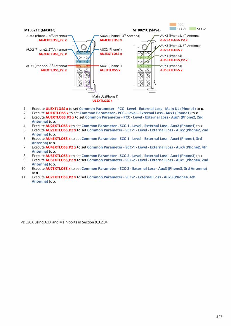
1. Execute ULEXTLOSS x to set Common Parameter - PCC - Level - External Loss - Main UL (Phone1) to x. 2. Execute AUEXTLOSS x to set Common Parameter - PCC - Level - External Loss - Aux1 (Phone1) to x. 3. Execute AUEXTLOSS_P2 x to set Common Parameter - PCC - Level - External Loss - Aux1 (Phone2, 2nd
Antenna) to x. 4. Execute AU2EXTLOSS x to set Common Parameter - SCC-1 - Level - External Loss - Aux2 (Phone1) to x. 5. Execute AU2EXTLOSS_P2 x to set Common Parameter - SCC-1 - Level - External Loss - Aux2 (Phone2, 2nd
Antenna) to x. 6. Execute AU4EXTLOSS x to set Common Parameter - SCC-1 - Level - External Loss - Aux4 (Phone1, 3rd
Antenna) to x. 7. Execute AU4EXTLOSS_P2 x to set Common Parameter - SCC-1 - Level - External Loss - Aux4 (Phone2, 4th
Antenna) to x. 8. Execute AU5EXTLOSS x to set Common Parameter - SCC-2 - Level - External Loss - Aux1 (Phone3) to x. 9. Execute AU5EXTLOSS_P2 x to set Common Parameter - SCC-2 - Level - External Loss - Aux1 (Phone4, 2nd
Antenna) to x. 10. Execute AU7EXTLOSS x to set Common Parameter - SCC-2 - External Loss - Aux3 (Phone3, 3rd Antenna)
to x. 11. Execute AU7EXTLOSS_P2 x to set Common Parameter - SCC-2 - External Loss - Aux3 (Phone4, 4th
Antenna) to x. <DL3CA using AUX and Main ports in Section 9.3.2.3>
AUX2 (Phone2, 2nd Antenna) AU2EXTLOSS_P2 x
AUX1 (Phone2, 2nd Antenna) AUEXTLOSS_P2 x
MT8821C (Master) MT8821C (Slave) AUX4 (Phone1, 3rd Antenna) AU4EXTLOSS x
AUX2 (Phone1) AU2EXTLOSS x
AUX1 (Phone1) AUEXTLOSS x
AUX4 (Phone2, 4th Antenna) AU4EXTLOSS_P2 x
Main UL (Phone1) ULEXTLOSS x
AUX3 (Phone4, 4th Antenna) AU7EXTLOSS_P2 x
AUX1 (Phone4) AU5EXTLOSS_P2 x
AUX1 (Phone3) AU5EXTLOSS x
AUX3 (Phone3, 3rd Antenna) AU7EXTLOSS x
PCC SCC-1 SCC-2
347
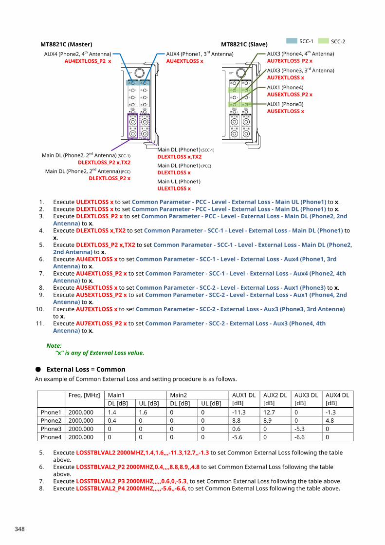
1. Execute ULEXTLOSS x to set Common Parameter - PCC - Level - External Loss - Main UL (Phone1) to x. 2. Execute DLEXTLOSS x to set Common Parameter - PCC - Level - External Loss - Main DL (Phone1) to x. 3. Execute DLEXTLOSS_P2 x to set Common Parameter - PCC - Level - External Loss - Main DL (Phone2, 2nd
Antenna) to x. 4. Execute DLEXTLOSS x,TX2 to set Common Parameter - SCC-1 - Level - External Loss - Main DL (Phone1) to
x. 5. Execute DLEXTLOSS_P2 x,TX2 to set Common Parameter - SCC-1 - Level - External Loss - Main DL (Phone2,
2nd Antenna) to x. 6. Execute AU4EXTLOSS x to set Common Parameter - SCC-1 - Level - External Loss - Aux4 (Phone1, 3rd
Antenna) to x. 7. Execute AU4EXTLOSS_P2 x to set Common Parameter - SCC-1 - Level - External Loss - Aux4 (Phone2, 4th
Antenna) to x. 8. Execute AU5EXTLOSS x to set Common Parameter - SCC-2 - Level - External Loss - Aux1 (Phone3) to x. 9. Execute AU5EXTLOSS_P2 x to set Common Parameter - SCC-2 - Level - External Loss - Aux1 (Phone4, 2nd
Antenna) to x. 10. Execute AU7EXTLOSS x to set Common Parameter - SCC-2 - External Loss - Aux3 (Phone3, 3rd Antenna)
to x. 11. Execute AU7EXTLOSS_P2 x to set Common Parameter - SCC-2 - External Loss - Aux3 (Phone4, 4th
Antenna) to x.
Note: “x” is any of External Loss value.
● External Loss = Common An example of Common External Loss and setting procedure is as follows.
Freq. [MHz] Main1 Main2 AUX1 DL [dB]
AUX2 DL [dB]
AUX3 DL [dB]
AUX4 DL [dB] DL [dB] UL [dB] DL [dB] UL [dB]
Phone1 2000.000 1.4 1.6 0 0 -11.3 12.7 0 -1.3 Phone2 2000.000 0.4 0 0 0 8.8 8.9 0 4.8 Phone3 2000.000 0 0 0 0 0.6 0 -5.3 0 Phone4 2000.000 0 0 0 0 -5.6 0 -6.6 0
5. Execute LOSSTBLVAL2 2000MHZ,1.4,1.6,,,-11.3,12.7,,-1.3 to set Common External Loss following the table
above. 6. Execute LOSSTBLVAL2_P2 2000MHZ,0.4,,,,8.8,8.9,,4.8 to set Common External Loss following the table
above. 7. Execute LOSSTBLVAL2_P3 2000MHZ,,,,,0.6,0,-5.3, to set Common External Loss following the table above. 8. Execute LOSSTBLVAL2_P4 2000MHZ,,,,,-5.6,,-6.6, to set Common External Loss following the table above.
MT8821C (Master) MT8821C (Slave) AUX4 (Phone1, 3rd Antenna) AU4EXTLOSS x
AUX4 (Phone2, 4th Antenna) AU4EXTLOSS_P2 x
Main DL (Phone1) (SCC-1)
DLEXTLOSS x,TX2
Main DL (Phone1) (PCC)
DLEXTLOSS x
Main UL (Phone1) ULEXTLOSS x
Main DL (Phone2, 2nd Antenna) (SCC-1)
DLEXTLOSS_P2 x,TX2
Main DL (Phone2, 2nd Antenna) (PCC)
DLEXTLOSS_P2 x
AUX3 (Phone4, 4th Antenna) AU7EXTLOSS_P2 x
AUX1 (Phone4) AU5EXTLOSS_P2 x
AUX1 (Phone3) AU5EXTLOSS x
AUX3 (Phone3, 3rd Antenna) AU7EXTLOSS x
SCC-2 SCC-1
348
Note: This value of Common External Loss is a sample.
9.3.4.3. Routing <DL3CA using AUX ports in Section 9.3.2.2>
1. Execute TXOUT 1,AUX to set Phone1 TX1 to AUX1. 2. Execute TXOUT 2,AUX to set Phone1 TX2 to AUX2. 3. Execute TXOUT 4,AUX to set Phone1 TX4 to AUX4. 4. Execute TXOUT_P2 1,AUX to set Phone2 TX1 to AUX1. 5. Execute TXOUT_P2 2,AUX to set Phone2 TX2 to AUX2. 6. Execute TXOUT_P2 4,AUX to set Phone2 TX4 to AUX4. 7. Execute TXOUT_P3 1,AUX to set Phone3 TX1 to AUX1. 8. Execute TXOUT_P3 3,AUX to set Phone3 TX3 to AUX3. 9. Execute TXOUT_P4 1,AUX to set Phone4 TX1 to AUX1.
10. Execute TXOUT_P4 3,AUX to set Phone4 TX3 to AUX3. <DL3CA using AUX and Main ports in Section 9.3.2.3>
1. Execute TXOUT 1,MAIN to set Phone1 TX1 to Main. 2. Execute TXOUT 2,MAIN to set Phone1 TX2 to Main. 3. Execute TXOUT 4,AUX to set Phone1 TX4 to AUX4. 4. Execute TXOUT_P2 1,MAIN to set Phone2 TX1 to Main. 5. Execute TXOUT_P2 2,MAIN to set Phone2 TX2 to Main. 6. Execute TXOUT_P2 4,AUX to set Phone2 TX4 to AUX4. 7. Execute TXOUT_P3 1,AUX to set Phone3 TX1 to AUX1. 8. Execute TXOUT_P3 3,AUX to set Phone3 TX3 to AUX3. 9. Execute TXOUT_P4 1,AUX to set Phone4 TX1 to AUX1.
10. Execute TXOUT_P4 3,AUX to set Phone4 TX3 to AUX3. 9.3.4.4. Call Connection
1. Connect UE and MT8821. 2. Execute CALLSO to clear the call processing status. 3. Execute CALLSTAT? to confirm the call processing status is 1 (= Idle). 4. Turn on UE power. 5. Execute CALLSTAT? to confirm the call processing status is 2 (= Idle (Regist)). 6. Execute CALLSA to connect to Test Mode. 7. Execute CALLSTATIC? to confirm the call processing stationary status is 6 (= Connected).
9.3.4.5. Measurement
1. Execute TPUT_MEAS ON to set Throughput Measurement to On. 2. Execute SWP to measure the power. 3. Execute TPUT? to confirm the Total Throughput measurement result. 4. Execute TPUT? PCC to confirm the PCC Throughput measurement result. 5. Execute TPUT? SCC1 to confirm the SCC1 Throughput measurement result. 6. Execute TPUT? SCC2 to confirm the SCC2 Throughput measurement result. 7. Execute TPUT_BLERCNTNACK? to confirm the Total Error Count (NACK). 8. Execute TPUT_BLERCNTNACK? PCC to confirm the PCC Error Count (NACK). 9. Execute TPUT_BLERCNTNACK? SCC1 to confirm the SCC1 Error Count (NACK).
10. Execute TPUT_BLERCNTNACK? SCC2 to confirm the SCC2 Error Count (NACK). 11. Execute TPUT_BLERCNTDTX? to confirm the Total Error Count (DTX). 12. Execute TPUT_BLERCNTDTX? PCC to confirm the PCC Error Count (DTX). 13. Execute TPUT_BLERCNTDTX? SCC1 to confirm the SCC1 Error Count (DTX). 14. Execute TPUT_BLERCNTDTX? SCC2 to confirm the SCC2 Error Count (DTX).
4DL CA without UL CA 9.4.This chapter describes the DL 4CA 4x4 MIMO connection using the MT8821C.
Overview 9.4.1.This chapter describes the procedure to perform the DL 4CA MIMO function by controlling two MT8821C units when one MT8821C is the Master and the other is the Slave. Users perform all operations with the exception of
349
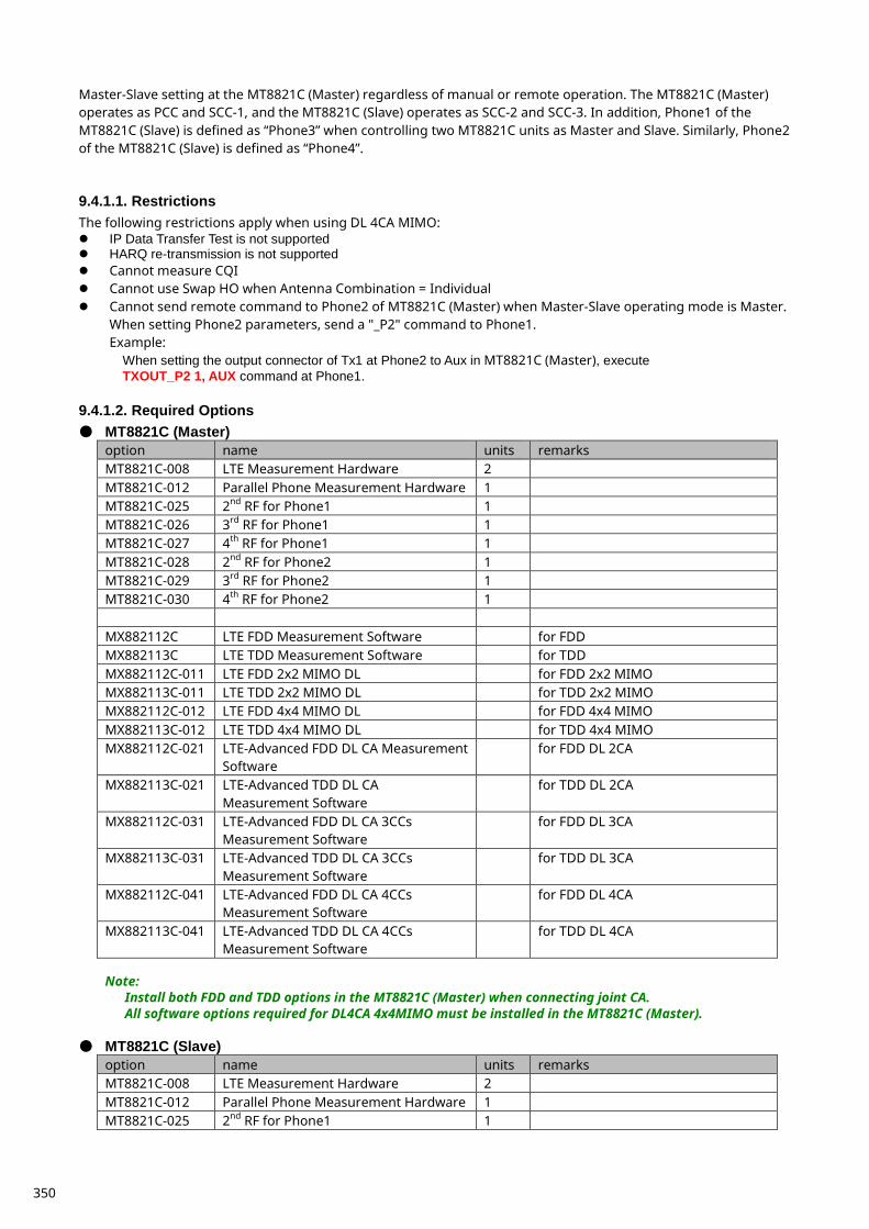
Master-Slave setting at the MT8821C (Master) regardless of manual or remote operation. The MT8821C (Master) operates as PCC and SCC-1, and the MT8821C (Slave) operates as SCC-2 and SCC-3. In addition, Phone1 of the MT8821C (Slave) is defined as “Phone3” when controlling two MT8821C units as Master and Slave. Similarly, Phone2 of the MT8821C (Slave) is defined as “Phone4”. 9.4.1.1. Restrictions The following restrictions apply when using DL 4CA MIMO: IP Data Transfer Test is not supported HARQ re-transmission is not supported Cannot measure CQI Cannot use Swap HO when Antenna Combination = Individual Cannot send remote command to Phone2 of MT8821C (Master) when Master-Slave operating mode is Master.
When setting Phone2 parameters, send a "_P2" command to Phone1. Example:
When setting the output connector of Tx1 at Phone2 to Aux in MT8821C (Master), execute TXOUT_P2 1, AUX command at Phone1.
9.4.1.2. Required Options ● MT8821C (Master)
option name units remarks MT8821C-008 LTE Measurement Hardware 2 MT8821C-012 Parallel Phone Measurement Hardware 1 MT8821C-025 2nd RF for Phone1 1 MT8821C-026 3rd RF for Phone1 1 MT8821C-027 4th RF for Phone1 1 MT8821C-028 2nd RF for Phone2 1 MT8821C-029 3rd RF for Phone2 1 MT8821C-030 4th RF for Phone2 1 MX882112C LTE FDD Measurement Software for FDD MX882113C LTE TDD Measurement Software for TDD MX882112C-011 LTE FDD 2x2 MIMO DL for FDD 2x2 MIMO MX882113C-011 LTE TDD 2x2 MIMO DL for TDD 2x2 MIMO MX882112C-012 LTE FDD 4x4 MIMO DL for FDD 4x4 MIMO MX882113C-012 LTE TDD 4x4 MIMO DL for TDD 4x4 MIMO MX882112C-021 LTE-Advanced FDD DL CA Measurement
Software for FDD DL 2CA
MX882113C-021 LTE-Advanced TDD DL CA Measurement Software
for TDD DL 2CA
MX882112C-031 LTE-Advanced FDD DL CA 3CCs Measurement Software
for FDD DL 3CA
MX882113C-031 LTE-Advanced TDD DL CA 3CCs Measurement Software
for TDD DL 3CA
MX882112C-041 LTE-Advanced FDD DL CA 4CCs Measurement Software
for FDD DL 4CA
MX882113C-041 LTE-Advanced TDD DL CA 4CCs Measurement Software
for TDD DL 4CA
Note:
Install both FDD and TDD options in the MT8821C (Master) when connecting joint CA. All software options required for DL4CA 4x4MIMO must be installed in the MT8821C (Master).
● MT8821C (Slave)
option name units remarks MT8821C-008 LTE Measurement Hardware 2 MT8821C-012 Parallel Phone Measurement Hardware 1 MT8821C-025 2nd RF for Phone1 1
350
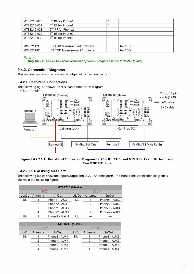
MT8821C-026 3rd RF for Phone1 1 MT8821C-027 4th RF for Phone1 1 MT8821C-028 2nd RF for Phone2 1 MT8821C-029 3rd RF for Phone2 1 MT8821C-030 4th RF for Phone2 1 MX882112C LTE FDD Measurement Software for FDD MX882113C LTE TDD Measurement Software for TDD
Note:
Only the LTE FDD or TDD Measurement Software is required in the MT8821C (Slave).
Connection Diagrams 9.4.2.This section describes the rear and front-panel connection diagrams. 9.4.2.1. Rear-Panel Connections The following figure shows the rear-panel connection diagram.
Figure 9.4.2.2.1-1 Rear-Panel Connection Diagram for 4DL/1UL CA DL 4x4 MIMO for Tx and Rx Test using
Two MT8821C Units 9.4.2.2. DL4CA using AUX Ports The following tables show the Input/Output and UL/DL Antenna ports. The front-panel connection diagram is shown in the following figure.
MT8821C (Master) PCC SCC1
UL/DL Antenna InOut UL/DL Antenna InOut DL 1 Phone1 - AUX1 DL 1 Phone1 - AUX2
2 Phone2 - AUX1 2 Phone2 - AUX2 3 Phone1 - AUX3 3 Phone1 - AUX4 4 Phone2 - AUX3 4 Phone2 - AUX4
UL 1 Phone1 - Main1 UL --- ---
MT8821C (Slave) SCC2 SCC3
UL/DL Antenna InOut UL/DL Antenna InOut DL 1 Phone3 - AUX1 DL 1 Phone3 - AUX2
2 Phone4 - AUX1 2 Phone4 - AUX2 3 Phone3 - AUX3 3 Phone3 - AUX4 4 Phone4 - AUX3 4 Phone4 - AUX4
MT8821C (Master) MT8821C (Slave)
Control PC
Remote 1 Call Proc I/O 1 Call Proc I/O 1
Remote 2 Remote 1 10 MHz Buf Out 10 MHz/13 MHz Ref In
<Rear Panel> D-sub 15 pin cable J1249
LAN cable
BNC cable
351
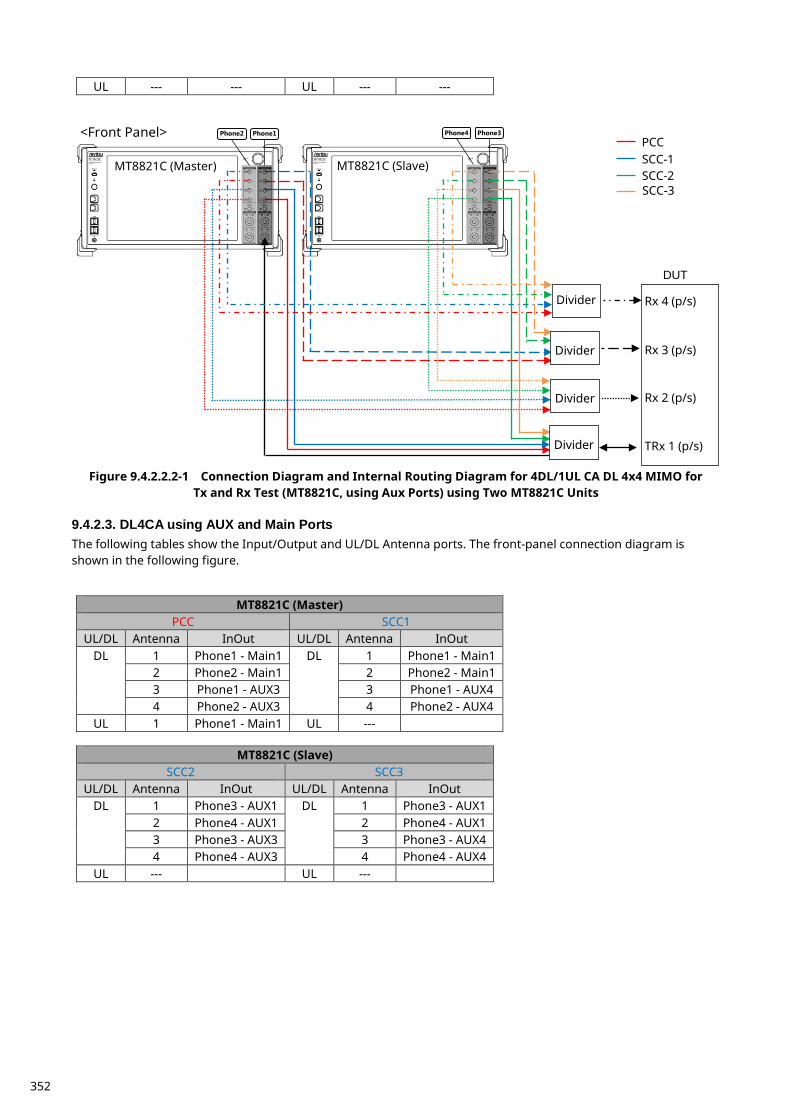
UL --- --- UL --- ---
Figure 9.4.2.2.2-1 Connection Diagram and Internal Routing Diagram for 4DL/1UL CA DL 4x4 MIMO for
Tx and Rx Test (MT8821C, using Aux Ports) using Two MT8821C Units 9.4.2.3. DL4CA using AUX and Main Ports The following tables show the Input/Output and UL/DL Antenna ports. The front-panel connection diagram is shown in the following figure.
MT8821C (Master) PCC SCC1
UL/DL Antenna InOut UL/DL Antenna InOut DL 1 Phone1 - Main1 DL 1 Phone1 - Main1
2 Phone2 - Main1 2 Phone2 - Main1 3 Phone1 - AUX3 3 Phone1 - AUX4 4 Phone2 - AUX3 4 Phone2 - AUX4
UL 1 Phone1 - Main1 UL ---
MT8821C (Slave) SCC2 SCC3
UL/DL Antenna InOut UL/DL Antenna InOut DL 1 Phone3 - AUX1 DL 1 Phone3 - AUX1
2 Phone4 - AUX1 2 Phone4 - AUX1 3 Phone3 - AUX3 3 Phone3 - AUX4 4 Phone4 - AUX3 4 Phone4 - AUX4
UL --- UL ---
Rx 4 (p/s)
Rx 3 (p/s)
Rx 2 (p/s)
TRx 1 (p/s)
DUT
Divider
MT8821C (Master) MT8821C (Slave)
<Front Panel> Phone1 Phone2 Phone3 Phone4
SCC-1 SCC-2
PCC
SCC-3
Divider
Divider
Divider
352
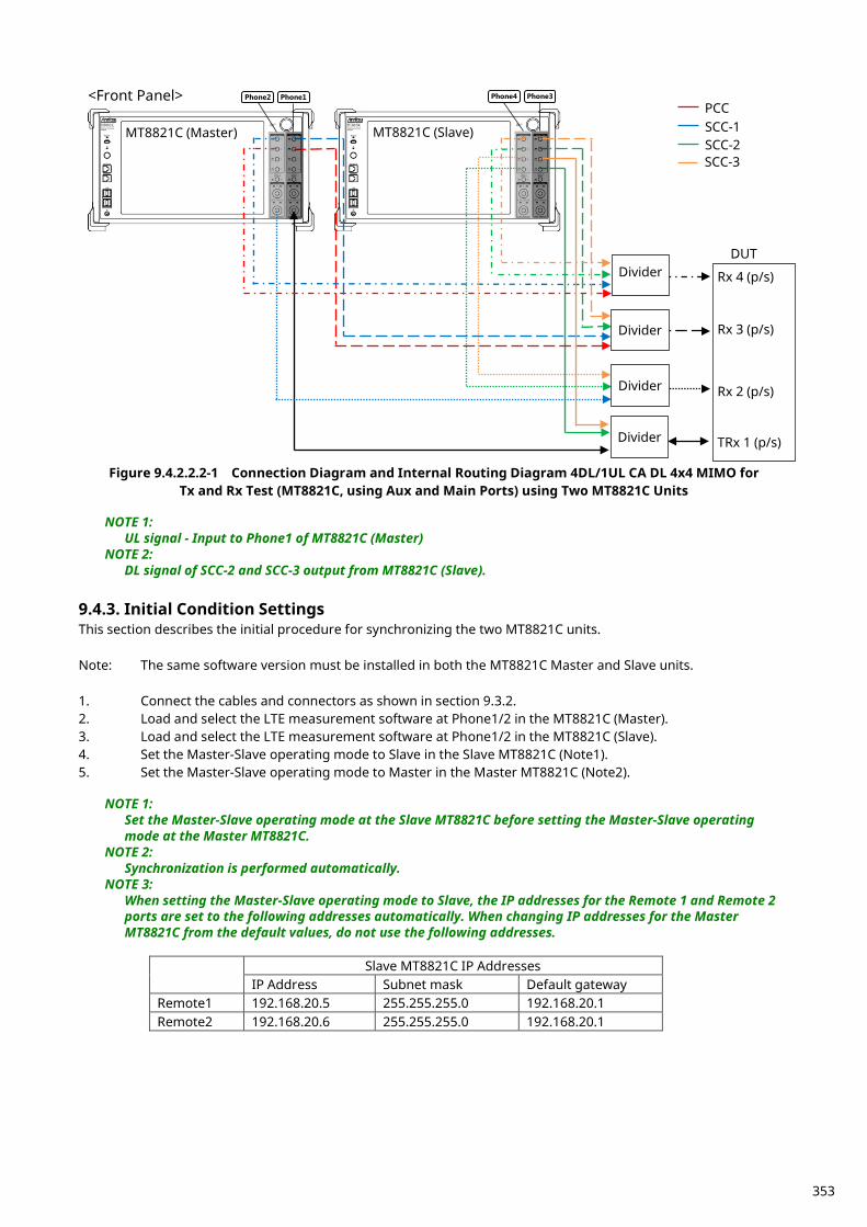
Figure 9.4.2.2.2-1 Connection Diagram and Internal Routing Diagram 4DL/1UL CA DL 4x4 MIMO for
Tx and Rx Test (MT8821C, using Aux and Main Ports) using Two MT8821C Units
NOTE 1: UL signal - Input to Phone1 of MT8821C (Master)
NOTE 2: DL signal of SCC-2 and SCC-3 output from MT8821C (Slave).
Initial Condition Settings 9.4.3.This section describes the initial procedure for synchronizing the two MT8821C units. Note: The same software version must be installed in both the MT8821C Master and Slave units. 1. Connect the cables and connectors as shown in section 9.3.2. 2. Load and select the LTE measurement software at Phone1/2 in the MT8821C (Master). 3. Load and select the LTE measurement software at Phone1/2 in the MT8821C (Slave). 4. Set the Master-Slave operating mode to Slave in the Slave MT8821C (Note1). 5. Set the Master-Slave operating mode to Master in the Master MT8821C (Note2).
NOTE 1: Set the Master-Slave operating mode at the Slave MT8821C before setting the Master-Slave operating mode at the Master MT8821C.
NOTE 2: Synchronization is performed automatically.
NOTE 3: When setting the Master-Slave operating mode to Slave, the IP addresses for the Remote 1 and Remote 2 ports are set to the following addresses automatically. When changing IP addresses for the Master MT8821C from the default values, do not use the following addresses.
Slave MT8821C IP Addresses
IP Address Subnet mask Default gateway Remote1 192.168.20.5 255.255.255.0 192.168.20.1 Remote2 192.168.20.6 255.255.255.0 192.168.20.1
Rx 4 (p/s)
Rx 3 (p/s)
Rx 2 (p/s)
TRx 1 (p/s)
DUT Divider
MT8821C (Master) MT8821C (Slave)
<Front Panel> Phone1 Phone2 Phone3 Phone4
SCC-1 SCC-2
PCC
SCC-3
Divider
Divider
Divider
353
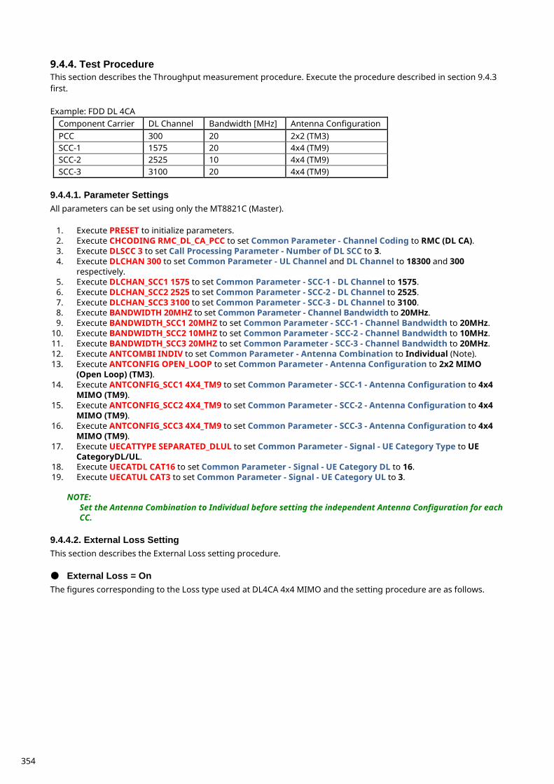
Test Procedure 9.4.4.This section describes the Throughput measurement procedure. Execute the procedure described in section 9.4.3 first. Example: FDD DL 4CA
Component Carrier DL Channel Bandwidth [MHz] Antenna Configuration PCC 300 20 2x2 (TM3) SCC-1 1575 20 4x4 (TM9) SCC-2 2525 10 4x4 (TM9) SCC-3 3100 20 4x4 (TM9)
9.4.4.1. Parameter Settings All parameters can be set using only the MT8821C (Master).
1. Execute PRESET to initialize parameters. 2. Execute CHCODING RMC_DL_CA_PCC to set Common Parameter - Channel Coding to RMC (DL CA). 3. Execute DLSCC 3 to set Call Processing Parameter - Number of DL SCC to 3. 4. Execute DLCHAN 300 to set Common Parameter - UL Channel and DL Channel to 18300 and 300
respectively. 5. Execute DLCHAN_SCC1 1575 to set Common Parameter - SCC-1 - DL Channel to 1575. 6. Execute DLCHAN_SCC2 2525 to set Common Parameter - SCC-2 - DL Channel to 2525. 7. Execute DLCHAN_SCC3 3100 to set Common Parameter - SCC-3 - DL Channel to 3100. 8. Execute BANDWIDTH 20MHZ to set Common Parameter - Channel Bandwidth to 20MHz. 9. Execute BANDWIDTH_SCC1 20MHZ to set Common Parameter - SCC-1 - Channel Bandwidth to 20MHz.
10. Execute BANDWIDTH_SCC2 10MHZ to set Common Parameter - SCC-2 - Channel Bandwidth to 10MHz. 11. Execute BANDWIDTH_SCC3 20MHZ to set Common Parameter - SCC-3 - Channel Bandwidth to 20MHz. 12. Execute ANTCOMBI INDIV to set Common Parameter - Antenna Combination to Individual (Note). 13. Execute ANTCONFIG OPEN_LOOP to set Common Parameter - Antenna Configuration to 2x2 MIMO
(Open Loop) (TM3). 14. Execute ANTCONFIG_SCC1 4X4_TM9 to set Common Parameter - SCC-1 - Antenna Configuration to 4x4
MIMO (TM9). 15. Execute ANTCONFIG_SCC2 4X4_TM9 to set Common Parameter - SCC-2 - Antenna Configuration to 4x4
MIMO (TM9). 16. Execute ANTCONFIG_SCC3 4X4_TM9 to set Common Parameter - SCC-3 - Antenna Configuration to 4x4
MIMO (TM9). 17. Execute UECATTYPE SEPARATED_DLUL to set Common Parameter - Signal - UE Category Type to UE
CategoryDL/UL. 18. Execute UECATDL CAT16 to set Common Parameter - Signal - UE Category DL to 16. 19. Execute UECATUL CAT3 to set Common Parameter - Signal - UE Category UL to 3.
NOTE: Set the Antenna Combination to Individual before setting the independent Antenna Configuration for each CC.
9.4.4.2. External Loss Setting This section describes the External Loss setting procedure. ● External Loss = On The figures corresponding to the Loss type used at DL4CA 4x4 MIMO and the setting procedure are as follows.
354
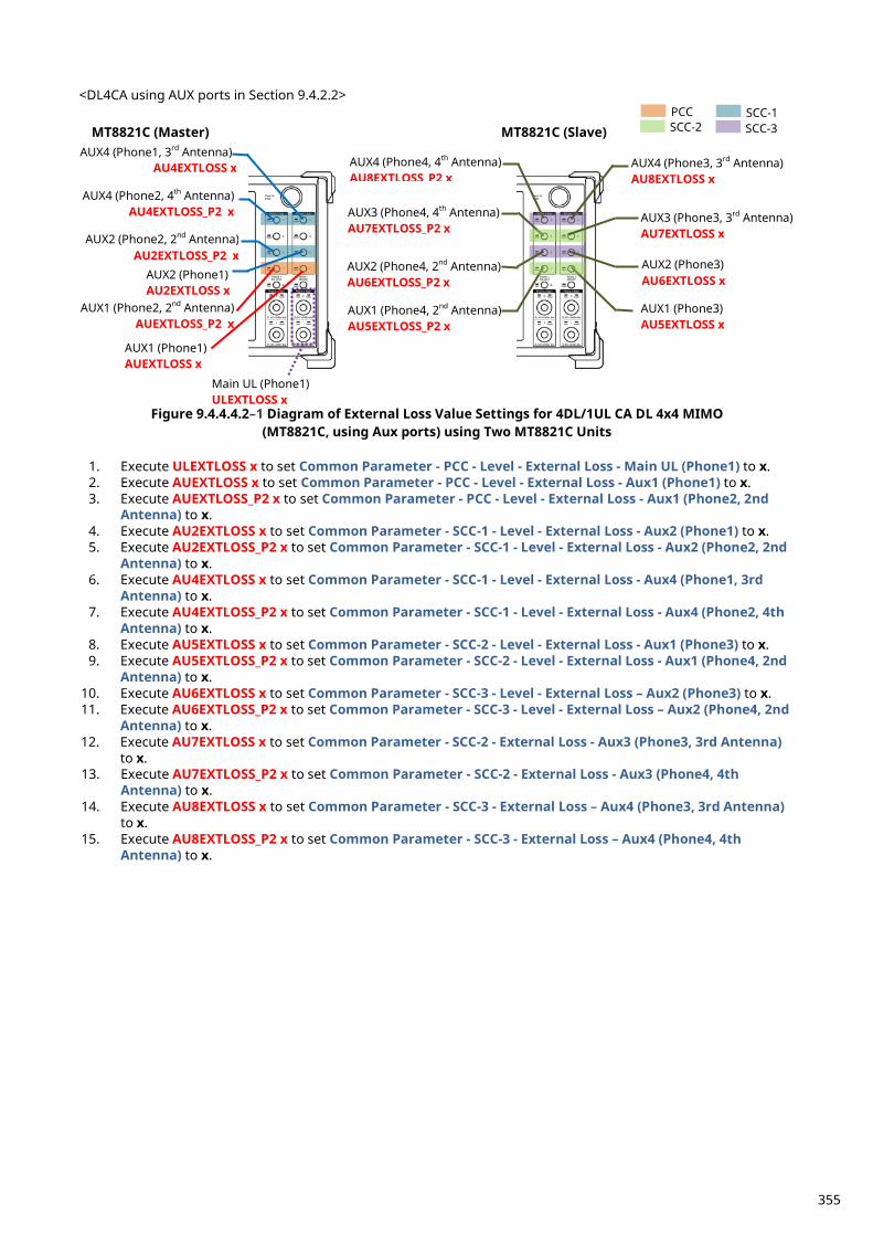
<DL4CA using AUX ports in Section 9.4.2.2>
Figure 9.4.4.4.2–1 Diagram of External Loss Value Settings for 4DL/1UL CA DL 4x4 MIMO
(MT8821C, using Aux ports) using Two MT8821C Units
1. Execute ULEXTLOSS x to set Common Parameter - PCC - Level - External Loss - Main UL (Phone1) to x. 2. Execute AUEXTLOSS x to set Common Parameter - PCC - Level - External Loss - Aux1 (Phone1) to x. 3. Execute AUEXTLOSS_P2 x to set Common Parameter - PCC - Level - External Loss - Aux1 (Phone2, 2nd
Antenna) to x. 4. Execute AU2EXTLOSS x to set Common Parameter - SCC-1 - Level - External Loss - Aux2 (Phone1) to x. 5. Execute AU2EXTLOSS_P2 x to set Common Parameter - SCC-1 - Level - External Loss - Aux2 (Phone2, 2nd
Antenna) to x. 6. Execute AU4EXTLOSS x to set Common Parameter - SCC-1 - Level - External Loss - Aux4 (Phone1, 3rd
Antenna) to x. 7. Execute AU4EXTLOSS_P2 x to set Common Parameter - SCC-1 - Level - External Loss - Aux4 (Phone2, 4th
Antenna) to x. 8. Execute AU5EXTLOSS x to set Common Parameter - SCC-2 - Level - External Loss - Aux1 (Phone3) to x. 9. Execute AU5EXTLOSS_P2 x to set Common Parameter - SCC-2 - Level - External Loss - Aux1 (Phone4, 2nd
Antenna) to x. 10. Execute AU6EXTLOSS x to set Common Parameter - SCC-3 - Level - External Loss – Aux2 (Phone3) to x. 11. Execute AU6EXTLOSS_P2 x to set Common Parameter - SCC-3 - Level - External Loss – Aux2 (Phone4, 2nd
Antenna) to x. 12. Execute AU7EXTLOSS x to set Common Parameter - SCC-2 - External Loss - Aux3 (Phone3, 3rd Antenna)
to x. 13. Execute AU7EXTLOSS_P2 x to set Common Parameter - SCC-2 - External Loss - Aux3 (Phone4, 4th
Antenna) to x. 14. Execute AU8EXTLOSS x to set Common Parameter - SCC-3 - External Loss – Aux4 (Phone3, 3rd Antenna)
to x. 15. Execute AU8EXTLOSS_P2 x to set Common Parameter - SCC-3 - External Loss – Aux4 (Phone4, 4th
Antenna) to x.
AUX2 (Phone2, 2nd Antenna) AU2EXTLOSS_P2 x
AUX1 (Phone2, 2nd Antenna) AUEXTLOSS_P2 x
MT8821C (Master) MT8821C (Slave) AUX4 (Phone1, 3rd Antenna)
AU4EXTLOSS x
AUX2 (Phone1) AU2EXTLOSS x
AUX1 (Phone1) AUEXTLOSS x
AUX4 (Phone2, 4th Antenna) AU4EXTLOSS_P2 x
Main UL (Phone1) ULEXTLOSS x
AUX3 (Phone4, 4th Antenna) AU7EXTLOSS_P2 x
AUX1 (Phone4, 2nd Antenna) AU5EXTLOSS_P2 x
AUX1 (Phone3) AU5EXTLOSS x
AUX3 (Phone3, 3rd Antenna) AU7EXTLOSS x
PCC SCC-1 SCC-3 SCC-2
AUX2 (Phone4, 2nd Antenna) AU6EXTLOSS_P2 x
AUX2 (Phone3) AU6EXTLOSS x
AUX4 (Phone3, 3rd Antenna) AU8EXTLOSS x
AUX4 (Phone4, 4th Antenna) AU8EXTLOSS P2 x
355
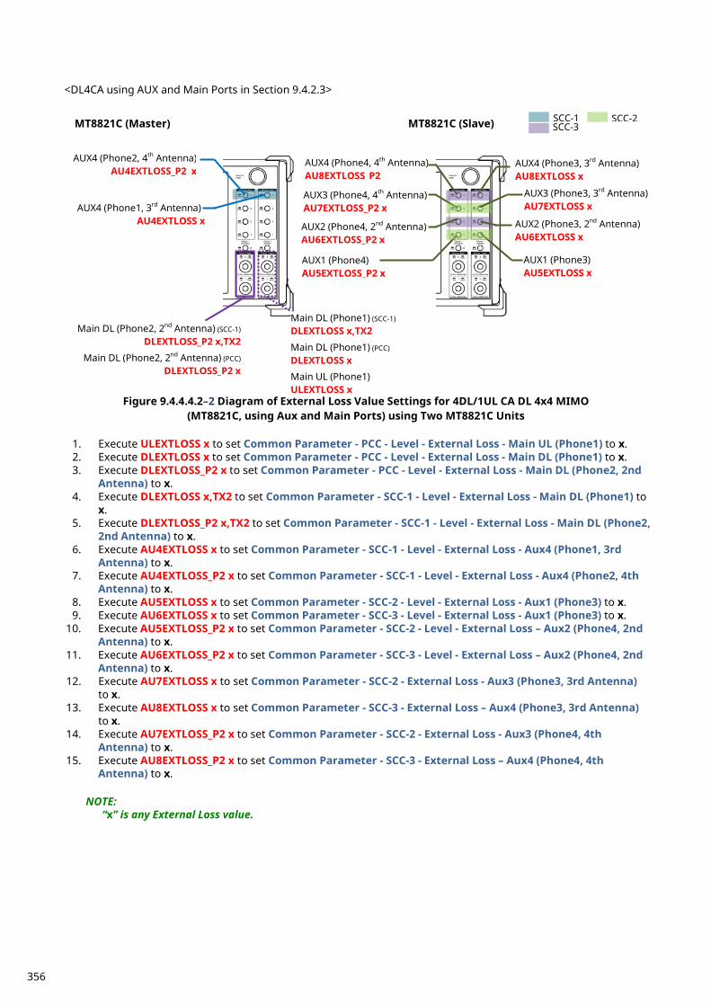
<DL4CA using AUX and Main Ports in Section 9.4.2.3>
Figure 9.4.4.4.2–2 Diagram of External Loss Value Settings for 4DL/1UL CA DL 4x4 MIMO
(MT8821C, using Aux and Main Ports) using Two MT8821C Units
1. Execute ULEXTLOSS x to set Common Parameter - PCC - Level - External Loss - Main UL (Phone1) to x. 2. Execute DLEXTLOSS x to set Common Parameter - PCC - Level - External Loss - Main DL (Phone1) to x. 3. Execute DLEXTLOSS_P2 x to set Common Parameter - PCC - Level - External Loss - Main DL (Phone2, 2nd
Antenna) to x. 4. Execute DLEXTLOSS x,TX2 to set Common Parameter - SCC-1 - Level - External Loss - Main DL (Phone1) to
x. 5. Execute DLEXTLOSS_P2 x,TX2 to set Common Parameter - SCC-1 - Level - External Loss - Main DL (Phone2,
2nd Antenna) to x. 6. Execute AU4EXTLOSS x to set Common Parameter - SCC-1 - Level - External Loss - Aux4 (Phone1, 3rd
Antenna) to x. 7. Execute AU4EXTLOSS_P2 x to set Common Parameter - SCC-1 - Level - External Loss - Aux4 (Phone2, 4th
Antenna) to x. 8. Execute AU5EXTLOSS x to set Common Parameter - SCC-2 - Level - External Loss - Aux1 (Phone3) to x. 9. Execute AU6EXTLOSS x to set Common Parameter - SCC-3 - Level - External Loss - Aux1 (Phone3) to x.
10. Execute AU5EXTLOSS_P2 x to set Common Parameter - SCC-2 - Level - External Loss – Aux2 (Phone4, 2nd Antenna) to x.
11. Execute AU6EXTLOSS_P2 x to set Common Parameter - SCC-3 - Level - External Loss – Aux2 (Phone4, 2nd Antenna) to x.
12. Execute AU7EXTLOSS x to set Common Parameter - SCC-2 - External Loss - Aux3 (Phone3, 3rd Antenna) to x.
13. Execute AU8EXTLOSS x to set Common Parameter - SCC-3 - External Loss – Aux4 (Phone3, 3rd Antenna) to x.
14. Execute AU7EXTLOSS_P2 x to set Common Parameter - SCC-2 - External Loss - Aux3 (Phone4, 4th Antenna) to x.
15. Execute AU8EXTLOSS_P2 x to set Common Parameter - SCC-3 - External Loss – Aux4 (Phone4, 4th Antenna) to x.
NOTE:
“x” is any External Loss value.
MT8821C (Master) MT8821C (Slave)
AUX4 (Phone1, 3rd Antenna) AU4EXTLOSS x
AUX4 (Phone2, 4th Antenna) AU4EXTLOSS_P2 x
Main DL (Phone1) (SCC-1)
DLEXTLOSS x,TX2
Main DL (Phone1) (PCC)
DLEXTLOSS x
Main UL (Phone1) ULEXTLOSS x
Main DL (Phone2, 2nd Antenna) (SCC-1)
DLEXTLOSS_P2 x,TX2
Main DL (Phone2, 2nd Antenna) (PCC)
DLEXTLOSS_P2 x
AUX3 (Phone4, 4th Antenna) AU7EXTLOSS_P2 x
AUX1 (Phone4) AU5EXTLOSS_P2 x
AUX1 (Phone3) AU5EXTLOSS x
AUX3 (Phone3, 3rd Antenna) AU7EXTLOSS x
SCC-2 SCC-1
AUX4 (Phone3, 3rd Antenna) AU8EXTLOSS x
AUX2 (Phone3, 2nd Antenna) AU6EXTLOSS x
AUX2 (Phone4, 2nd Antenna) AU6EXTLOSS_P2 x
AUX4 (Phone4, 4th Antenna) AU8EXTLOSS P2
SCC-3
356
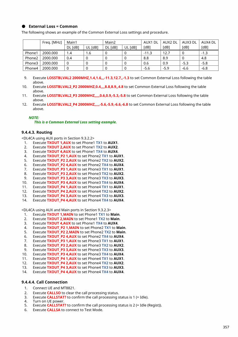
● External Loss = Common The following shows an example of the Common External Loss settings and procedure.
Freq. [MHz] Main1 Main2 AUX1 DL [dB]
AUX2 DL [dB]
AUX3 DL [dB]
AUX4 DL [dB] DL [dB] UL [dB] DL [dB] UL [dB]
Phone1 2000.000 1.4 1.6 0 0 -11.3 12.7 0 -1.3 Phone2 2000.000 0.4 0 0 0 8.8 8.9 0 4.8 Phone3 2000.000 0 0 0 0 0.6 0.9 -5.3 -5.8 Phone4 2000.000 0 0 0 0 -5.6 -5.9 -6.6 -6.8
9. Execute LOSSTBLVAL2 2000MHZ,1.4,1.6,,,-11.3,12.7,,-1.3 to set Common External Loss following the table
above. 10. Execute LOSSTBLVAL2_P2 2000MHZ,0.4,,,,8.8,8.9,,4.8 to set Common External Loss following the table
above. 11. Execute LOSSTBLVAL2_P3 2000MHZ,,,,,0.6,0.9,-5.3,-5.8 to set Common External Loss following the table
above. 12. Execute LOSSTBLVAL2_P4 2000MHZ,,,,,-5.6,-5.9,-6.6,-6.8 to set Common External Loss following the table
above.
NOTE: This is a Common External Loss setting example.
9.4.4.3. Routing <DL4CA using AUX ports in Section 9.3.2.2>
1. Execute TXOUT 1,AUX to set Phone1 TX1 to AUX1. 2. Execute TXOUT 2,AUX to set Phone1 TX2 to AUX2. 3. Execute TXOUT 4,AUX to set Phone1 TX4 to AUX4. 4. Execute TXOUT_P2 1,AUX to set Phone2 TX1 to AUX1. 5. Execute TXOUT_P2 2,AUX to set Phone2 TX2 to AUX2. 6. Execute TXOUT_P2 4,AUX to set Phone2 TX4 to AUX4. 7. Execute TXOUT_P3 1,AUX to set Phone3 TX1 to AUX1. 8. Execute TXOUT_P3 2,AUX to set Phone3 TX2 to AUX2. 9. Execute TXOUT_P3 3,AUX to set Phone3 TX3 to AUX3.
10. Execute TXOUT_P3 4,AUX to set Phone3 TX4 to AUX4. 11. Execute TXOUT_P4 1,AUX to set Phone4 TX1 to AUX1. 12. Execute TXOUT_P4 2,AUX to set Phone4 TX2 to AUX2. 13. Execute TXOUT_P4 3,AUX to set Phone4 TX3 to AUX3. 14. Execute TXOUT_P4 4,AUX to set Phone4 TX4 to AUX4. <DL4CA using AUX and Main ports in Section 9.3.2.3>
1. Execute TXOUT 1,MAIN to set Phone1 TX1 to Main. 2. Execute TXOUT 2,MAIN to set Phone1 TX2 to Main. 3. Execute TXOUT 4,AUX to set Phone1 TX4 to AUX4. 4. Execute TXOUT_P2 1,MAIN to set Phone2 TX1 to Main. 5. Execute TXOUT_P2 2,MAIN to set Phone2 TX2 to Main. 6. Execute TXOUT_P2 4,AUX to set Phone2 TX4 to AUX4. 7. Execute TXOUT_P3 1,AUX to set Phone3 TX1 to AUX1. 8. Execute TXOUT_P3 2,AUX to set Phone3 TX2 to AUX2. 9. Execute TXOUT_P3 3,AUX to set Phone3 TX3 to AUX3.
10. Execute TXOUT_P3 4,AUX to set Phone3 TX4 to AUX4. 11. Execute TXOUT_P4 1,AUX to set Phone4 TX1 to AUX1. 12. Execute TXOUT_P4 2,AUX to set Phone4 TX2 to AUX2. 13. Execute TXOUT_P4 3,AUX to set Phone4 TX3 to AUX3. 14. Execute TXOUT_P4 4,AUX to set Phone4 TX4 to AUX4. 9.4.4.4. Call Connection
1. Connect UE and MT8821. 2. Execute CALLSO to clear the call processing status. 3. Execute CALLSTAT? to confirm the call processing status is 1 (= Idle). 4. Turn on UE power. 5. Execute CALLSTAT? to confirm the call processing status is 2 (= Idle (Regist)). 6. Execute CALLSA to connect to Test Mode.
357
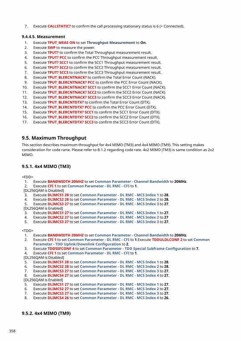
7. Execute CALLSTATIC? to confirm the call processing stationary status is 6 (= Connected). 9.4.4.5. Measurement
1. Execute TPUT_MEAS ON to set Throughput Measurement to On. 2. Execute SWP to measure the power. 3. Execute TPUT? to confirm the Total Throughput measurement result. 4. Execute TPUT? PCC to confirm the PCC Throughput measurement result. 5. Execute TPUT? SCC1 to confirm the SCC1 Throughput measurement result. 6. Execute TPUT? SCC2 to confirm the SCC2 Throughput measurement result. 7. Execute TPUT? SCC3 to confirm the SCC3 Throughput measurement result. 8. Execute TPUT_BLERCNTNACK? to confirm the Total Error Count (NACK). 9. Execute TPUT_BLERCNTNACK? PCC to confirm the PCC Error Count (NACK).
10. Execute TPUT_BLERCNTNACK? SCC1 to confirm the SCC1 Error Count (NACK). 11. Execute TPUT_BLERCNTNACK? SCC2 to confirm the SCC2 Error Count (NACK). 12. Execute TPUT_BLERCNTNACK? SCC3 to confirm the SCC3 Error Count (NACK). 13. Execute TPUT_BLERCNTDTX? to confirm the Total Error Count (DTX). 14. Execute TPUT_BLERCNTDTX? PCC to confirm the PCC Error Count (DTX). 15. Execute TPUT_BLERCNTDTX? SCC1 to confirm the SCC1 Error Count (DTX). 16. Execute TPUT_BLERCNTDTX? SCC2 to confirm the SCC2 Error Count (DTX). 17. Execute TPUT_BLERCNTDTX? SCC3 to confirm the SCC3 Error Count (DTX).
Maximum Throughput 9.5.This section describes maximum throughput for 4x4 MIMO (TM3) and 4x4 MIMO (TM9). This setting makes consideration for code rarte. Please refer to B.1.2 regarding code rate. 4x2 MIMO (TM3) is same condition as 2x2 MIMO.
4x4 MIMO (TM3) 9.5.1. <FDD>
1. Execute BANDWIDTH 20MHZ to set Common Parameter - Channel Bandwidth to 20MHz. 2. Execute CFI 1 to set Common Parameter - DL RMC - CFI to 1. [DL256QAM is Disabled] 3. Execute DLIMCS1 28 to set Common Parameter - DL RMC - MCS Index 1 to 28. 4. Execute DLIMCS2 28 to set Common Parameter - DL RMC - MCS Index 2 to 28. 5. Execute DLIMCS3 27 to set Common Parameter - DL RMC - MCS Index 3 to 27. [DL256QAM is Enabled] 3. Execute DLIMCS1 27 to set Common Parameter - DL RMC - MCS Index 1 to 27. 4. Execute DLIMCS2 27 to set Common Parameter - DL RMC - MCS Index 2 to 27 5. Execute DLIMCS3 27 to set Common Parameter - DL RMC - MCS Index 3 to 27.
<TDD>
1. Execute BANDWIDTH 20MHZ to set Common Parameter - Channel Bandwidth to 20MHz. 2. Execute CFI 1 to set Common Parameter - DL RMC - CFI to 1.Execute TDDULDLCONF 2 to set Common
Parameter - TDD Uplink/Downlink Configuration to 2. 3. Execute TDDSSFCONF 4 to set Common Parameter - TDD Special Subframe Configuration to 7. 4. Execute CFI 1 to set Common Parameter - DL RMC - CFI to 1. [DL256QAM is Disabled] 5. Execute DLIMCS1 28 to set Common Parameter - DL RMC - MCS Index 1 to 28. 6. Execute DLIMCS2 28 to set Common Parameter - DL RMC - MCS Index 2 to 28. 7. Execute DLIMCS3 27 to set Common Parameter - DL RMC - MCS Index 3 to 27. 8. Execute DLIMCS4 27 to set Common Parameter - DL RMC - MCS Index 4 to 27. [DL256QAM is Enabled] 5. Execute DLIMCS1 27 to set Common Parameter - DL RMC - MCS Index 1 to 27. 6. Execute DLIMCS2 27 to set Common Parameter - DL RMC - MCS Index 2 to 27. 7. Execute DLIMCS3 27 to set Common Parameter - DL RMC - MCS Index 3 to 27. 8. Execute DLIMCS4 26 to set Common Parameter - DL RMC - MCS Index 4 to 26.
4x4 MIMO (TM9) 9.5.2.
358
<FDD>
1. Execute BANDWIDTH 20MHZ to set Common Parameter - Channel Bandwidth to 20MHz. 2. Execute CFI 1 to set Common Parameter - DL RMC - CFI to 1. [DL256QAM is Disabled] 3. Execute DLIMCS1 27 to set Common Parameter - DL RMC - MCS Index 1 to 27. 4. Execute DLIMCS2 27 to set Common Parameter - DL RMC - MCS Index 2 to 27. 5. Execute DLIMCS3 27 to set Common Parameter - DL RMC - MCS Index 3 to 27. [DL256QAM is Enabled] 3. Execute DLIMCS1 26 to set Common Parameter - DL RMC - MCS Index 1 to 26. 4. Execute DLIMCS2 26 to set Common Parameter - DL RMC - MCS Index 2 to 26 5. Execute DLIMCS3 26 to set Common Parameter - DL RMC - MCS Index 3 to 26.
<TDD>
1. Execute BANDWIDTH 20MHZ to set Common Parameter - Channel Bandwidth to 20MHz. 2. Execute CFI 1 to set Common Parameter - DL RMC - CFI to 1. 3. Execute TDDULDLCONF 2 to set Common Parameter - TDD Uplink/Downlink Configuration to 2. 4. Execute TDDSSFCONF 4 to set Common Parameter - TDD Special Subframe Configuration to 7. 5. Execute CFI 1 to set Common Parameter - DL RMC - CFI to 1. [DL256QAM is Disabled] 6. Execute DLIMCS1 27 to set Common Parameter - DL RMC - MCS Index 1 to 27. 7. Execute DLIMCS2 27 to set Common Parameter - DL RMC - MCS Index 2 to 27. 8. Execute DLIMCS3 27 to set Common Parameter - DL RMC - MCS Index 3 to 27. 9. Execute DLIMCS4 24 to set Common Parameter - DL RMC - MCS Index 4 to 24. [DL256QAM is Enabled] 6. Execute DLIMCS1 26 to set Common Parameter - DL RMC - MCS Index 1 to 26. 7. Execute DLIMCS2 26 to set Common Parameter - DL RMC - MCS Index 2 to 26. 8. Execute DLIMCS3 26 to set Common Parameter - DL RMC - MCS Index 3 to 26. 9. Execute DLIMCS4 23 to set Common Parameter - DL RMC - MCS Index 4 to 23.
IP Data Transfer 9.6.Excluding the UE connection diagram, non CA and 2DL CA can be tested using the same procedure as chapter 5.1 and 5.3.
NOTE 1: IP Data Transfer test is supported up to 2DL CA.
NOTE 2:
Testing the DL CA IP Data Transfer requires two application servers and two EPS bearers must be established. The UE should support Multiple PDN Connection.
359
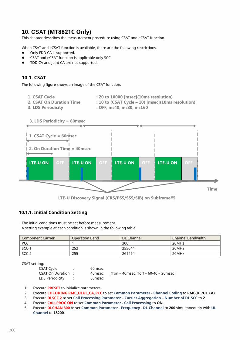
CSAT (MT8821C Only) 10.This chapter describes the measurement procedure using CSAT and eCSAT function. When CSAT and eCSAT function is available, there are the following restrictions. Only FDD CA is supported. CSAT and eCSAT function is applicable only SCC. TDD CA and Joint CA are not supported.
CSAT 10.1.The following figure shows an image of the CSAT function.
Initial Condition Setting 10.1.1. The initial conditions must be set before measurement. A setting example at each condition is shown in the following table. Component Carrier Operation Band DL Channel Channel Bandwidth PCC 1 300 20MHz SCC-1 252 255644 20MHz SCC-2 255 261494 20MHz CSAT setting:
CSAT Cycle : 60msec CSAT On Duration : 40msec (Ton = 40msec, Toff = 60-40 = 20msec)
LDS Periodicity : 80msec
1. Execute PRESET to initialize parameters. 2. Execute CHCODING RMC_DLUL_CA_PCC to set Common Parameter - Channel Coding to RMC(DL/UL CA). 3. Execute DLSCC 2 to set Call Processing Parameter – Carrier Aggregation – Number of DL SCC to 2. 4. Execute CALLPROC ON to set Common Parameter - Call Processing to ON. 5. Execute DLCHAN 300 to set Common Parameter - Frequency - DL Channel to 200 simultaneously with UL
Channel to 18200.
LTE-U ON OFF LTE-U ON OFF LTE-U ON OFF LTE-U ON OFF
1. CSAT Cycle = 60msec
2. On Duration Time = 40msec
3. LDS Periodicity = 80msec
Time
LTE-U Discovery Signal (CRS/PSS/SSS/SIB) on Subframe#5
1. CSAT Cycle : 20 to 10000 [msec](10ms resolution) 2. CSAT On Duration Time : 10 to (CSAT Cycle – 10) [msec](10ms resolution) 3. LDS Periodicity : OFF, ms40, ms80, ms160
360
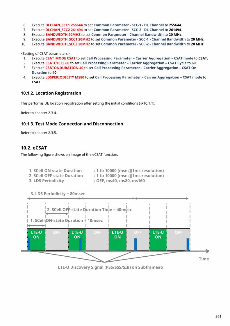
6. Execute DLCHAN_SCC1 255644 to set Common Parameter - SCC-1 - DL Channel to 255644. 7. Execute DLCHAN_SCC2 261494 to set Common Parameter - SCC-2 - DL Channel to 261494. 8. Execute BANDWIDTH 20MHZ to set Common Parameter - Channel Bandwidth to 20 MHz. 9. Execute BANDWIDTH_SCC1 20MHZ to set Common Parameter - SCC-1 - Channel Bandwidth to 20 MHz.
10. Execute BANDWIDTH_SCC2 20MHZ to set Common Parameter - SCC-2 - Channel Bandwidth to 20 MHz. <Setting of CSAT parameters>
1. Execute CSAT_MODE CSAT to set Call Processing Parameter – Carrier Aggregation – CSAT mode to CSAT. 2. Execute CSATCYCLE 60 to set Call Processing Parameter – Carrier Aggregation – CSAT Cycle to 60. 3. Execute CSATONDURATION 40 to set Call Processing Parameter – Carrier Aggregation – CSAT On
Duration to 40. 4. Execute LDSPERIODICITY MS80 to set Call Processing Parameter – Carrier Aggregation – CSAT mode to
CSAT.
Location Registration 10.1.2. This performs UE location registration after setting the initial conditions (10.1.1). Refer to chapter 2.3.4.
Test Mode Connection and Disconnection 10.1.3. Refer to chapter 2.3.5.
eCSAT 10.2.The following figure shows an image of the eCSAT function.
OFF OFF OFF LTE-U ON
LTE-U ON
LTE-U ON
LTE-U ON
OFF
1. SCell ON-state Duration = 10msec
3. LDS Periodicity = 80msec
Time
LTE-U Discovery Signal (PSS/SSS/SIB) on Subframe#5
1. SCell ON-state Duration : 1 to 10000 [msec](1ms resolution) 2. SCell OFF-state Duration : 1 to 10000 [msec](1ms resolution) 3. LDS Periodicity : OFF, ms40, ms80, ms160
2. SCell OFF-state Duration Time = 40msec
361
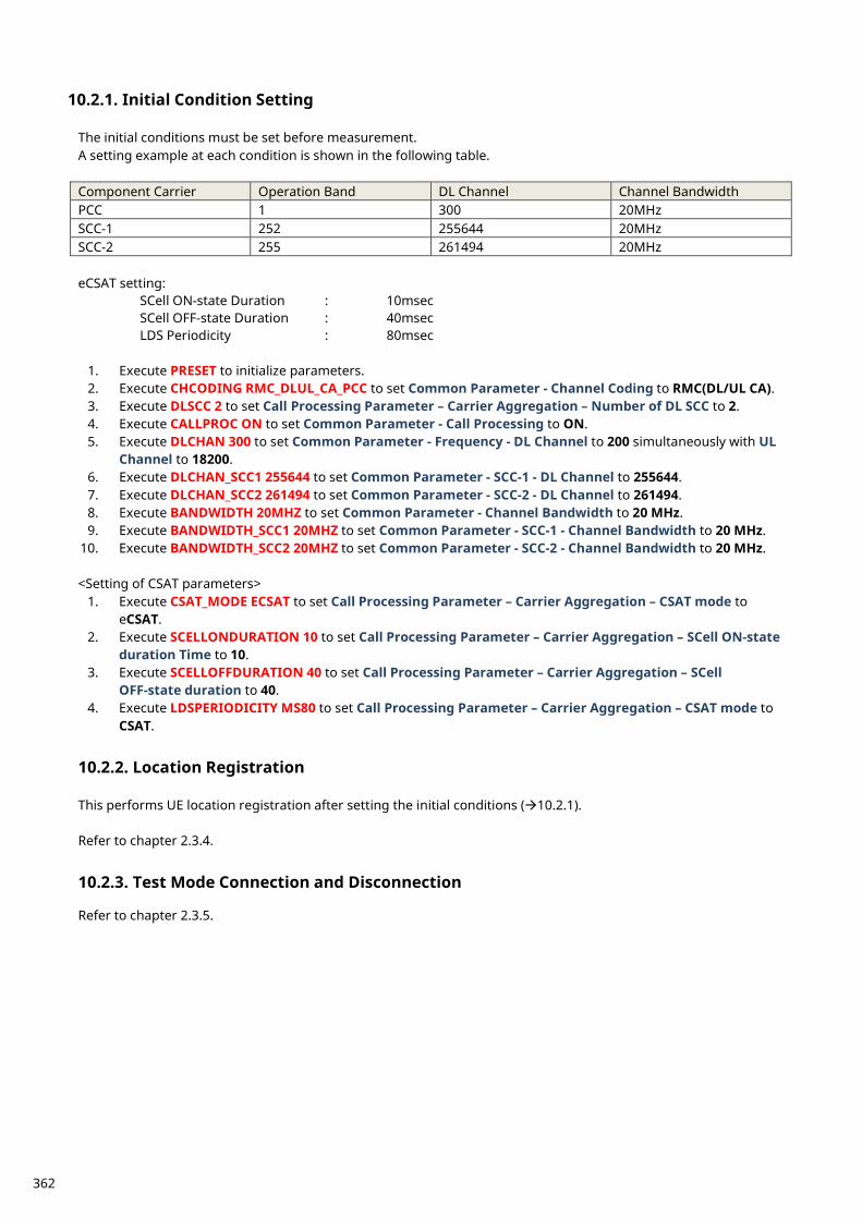
Initial Condition Setting 10.2.1. The initial conditions must be set before measurement. A setting example at each condition is shown in the following table. Component Carrier Operation Band DL Channel Channel Bandwidth PCC 1 300 20MHz SCC-1 252 255644 20MHz SCC-2 255 261494 20MHz eCSAT setting:
SCell ON-state Duration : 10msec SCell OFF-state Duration : 40msec
LDS Periodicity : 80msec
1. Execute PRESET to initialize parameters. 2. Execute CHCODING RMC_DLUL_CA_PCC to set Common Parameter - Channel Coding to RMC(DL/UL CA). 3. Execute DLSCC 2 to set Call Processing Parameter – Carrier Aggregation – Number of DL SCC to 2. 4. Execute CALLPROC ON to set Common Parameter - Call Processing to ON. 5. Execute DLCHAN 300 to set Common Parameter - Frequency - DL Channel to 200 simultaneously with UL
Channel to 18200. 6. Execute DLCHAN_SCC1 255644 to set Common Parameter - SCC-1 - DL Channel to 255644. 7. Execute DLCHAN_SCC2 261494 to set Common Parameter - SCC-2 - DL Channel to 261494. 8. Execute BANDWIDTH 20MHZ to set Common Parameter - Channel Bandwidth to 20 MHz. 9. Execute BANDWIDTH_SCC1 20MHZ to set Common Parameter - SCC-1 - Channel Bandwidth to 20 MHz.
10. Execute BANDWIDTH_SCC2 20MHZ to set Common Parameter - SCC-2 - Channel Bandwidth to 20 MHz. <Setting of CSAT parameters>
1. Execute CSAT_MODE ECSAT to set Call Processing Parameter – Carrier Aggregation – CSAT mode to eCSAT.
2. Execute SCELLONDURATION 10 to set Call Processing Parameter – Carrier Aggregation – SCell ON-state duration Time to 10.
3. Execute SCELLOFFDURATION 40 to set Call Processing Parameter – Carrier Aggregation – SCell OFF-state duration to 40.
4. Execute LDSPERIODICITY MS80 to set Call Processing Parameter – Carrier Aggregation – CSAT mode to CSAT.
Location Registration 10.2.2. This performs UE location registration after setting the initial conditions (10.2.1). Refer to chapter 2.3.4.
Test Mode Connection and Disconnection 10.2.3. Refer to chapter 2.3.5.
362
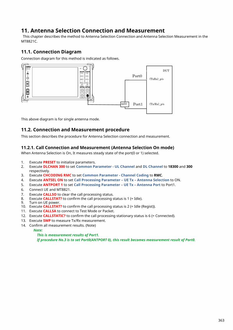
Antenna Selection Connection and Measurement 11.This chapter describes the method to Antenna Selection Connection and Antenna Selection Measurement in the
MT8821C.
Connection Diagram 11.1.Connection diagram for this method is indicated as follows.
DUT
(TxRx)_p/s
(Tx/Rx)_p/s split
Port0
Port1
This above diagram is for single antenna mode.
Connection and Measurement procedure 11.2.This section describes the procedure for Antenna Selection connection and measurement.
Call Connection and Measurement (Antenna Selection On mode) 11.2.1.When Antenna Selection is On, It measures steady state of the port(0 or 1) selected. 1. Execute PRESET to initialize parameters. 2. Execute DLCHAN 300 to set Common Parameter - UL Channel and DL Channel to 18300 and 300
respectively. 3. Execute CHCODING RMC to set Common Parameter - Channel Coding to RMC. 4. Execute ANTSEL ON to set Call Processing Parameter – UE Tx – Antenna Selection to ON. 5. Execute ANTPORT 1 to set Call Processing Parameter – UE Tx – Antenna Port to Port1. 6. Connect UE and MT8821. 7. Execute CALLSO to clear the call processing status. 8. Execute CALLSTAT? to confirm the call processing status is 1 (= Idle). 9. Turn on UE power. 10. Execute CALLSTAT? to confirm the call processing status is 2 (= Idle (Regist)). 11. Execute CALLSA to connect to Test Mode or Packet. 12. Execute CALLSTATIC? to confirm the call processing stationary status is 6 (= Connected). 13. Execute SWP to measure Tx/Rx measurement. 14. Confirm all measurement results. (Note)
Note: This is measurement results of Port1. If procedure No.3 is to set Port0(ANTPORT 0), this result becomes measurement result of Port0.
363
Call Connection and Measurement(Antenna Selection On(Alternate) mode) 11.2.2.When Antenna Selection is On(Alternate), it measures first UL signal immediately after changing Antenna Port. 1. Execute PRESET to initialize parameters. 2. Execute DLCHAN 300 to set Common Parameter - UL Channel and DL Channel to 18300 and 300
respectively. 3. Execute CHCODING RMC to set Common Parameter - Channel Coding to RMC. 4. Execute ANTSEL ON_ALT to set Call Processing Parameter – UE Tx – Antenna Selection to ON(Alternate). 5. Execute ANTPORT 0 to set Call Processing Parameter – UE Tx – Antenna Port to Port0. 6. Connect UE and MT8821. 7. Execute CALLSO to clear the call processing status. 8. Execute CALLSTAT? to confirm the call processing status is 1 (= Idle). 9. Turn on UE power. 10. Execute CALLSTAT? to confirm the call processing status is 2 (= Idle (Regist)). 11. Execute CALLSA to connect to Test Mode or Packet. 12. Execute CALLSTATIC? to confirm the call processing stationary status is 6 (= Connected). 13. Execute SWP to measure Tx/Rx measurement. 14. Execute ANTPORT? to confirm the Call Processing Parameter – UE Tx – Antenna Port is 1(= Port1). 15. Confirm all measurement results. (Note)
Note: This is measurement results of first Port1's UL signal immediately after the changing Antenna Port from Port0.If procedure No.3 is to set Port1(ANTPORT 1), this result becomes measurement result of Port0’s first UL signal.
Measurement Restrictions When Antenna Selection is On(Alternate), there are the following restrictions. The continuous(CONTS) measurement is identical with single(SWP) measurement.
*It can't perform continuous measurement. Measurement Item can be selected only "Normal". It includes Tx/Rx measurement items as bellow.
Power Measurement Occupied Bandwidth Spectrum Emission Mask Adjacent Channel Power
Modulation Analysis Throughput CQI
This function doesn’t support MIMO and UL CA.
364
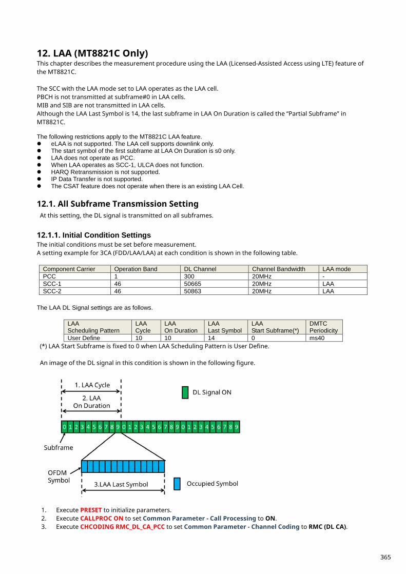
LAA (MT8821C Only) 12.This chapter describes the measurement procedure using the LAA (Licensed-Assisted Access using LTE) feature of the MT8821C. The SCC with the LAA mode set to LAA operates as the LAA cell. PBCH is not transmitted at subframe#0 in LAA cells. MIB and SIB are not transmitted in LAA cells. Although the LAA Last Symbol is 14, the last subframe in LAA On Duration is called the “Partial Subframe” in MT8821C. The following restrictions apply to the MT8821C LAA feature. eLAA is not supported. The LAA cell supports downlink only. The start symbol of the first subframe at LAA On Duration is s0 only. LAA does not operate as PCC. When LAA operates as SCC-1, ULCA does not function. HARQ Retransmission is not supported. IP Data Transfer is not supported. The CSAT feature does not operate when there is an existing LAA Cell.
All Subframe Transmission Setting 12.1.At this setting, the DL signal is transmitted on all subframes.
Initial Condition Settings 12.1.1.The initial conditions must be set before measurement. A setting example for 3CA (FDD/LAA/LAA) at each condition is shown in the following table.
Component Carrier Operation Band DL Channel Channel Bandwidth LAA mode PCC 1 300 20MHz - SCC-1 46 50665 20MHz LAA SCC-2 46 50863 20MHz LAA
The LAA DL Signal settings are as follows.
LAA Scheduling Pattern
LAA Cycle
LAA On Duration
LAA Last Symbol
LAA Start Subframe(*)
DMTC Periodicity
User Define 10 10 14 0 ms40 (*) LAA Start Subframe is fixed to 0 when LAA Scheduling Pattern is User Define. An image of the DL signal in this condition is shown in the following figure.
1. Execute PRESET to initialize parameters. 2. Execute CALLPROC ON to set Common Parameter - Call Processing to ON. 3. Execute CHCODING RMC_DL_CA_PCC to set Common Parameter - Channel Coding to RMC (DL CA).
365
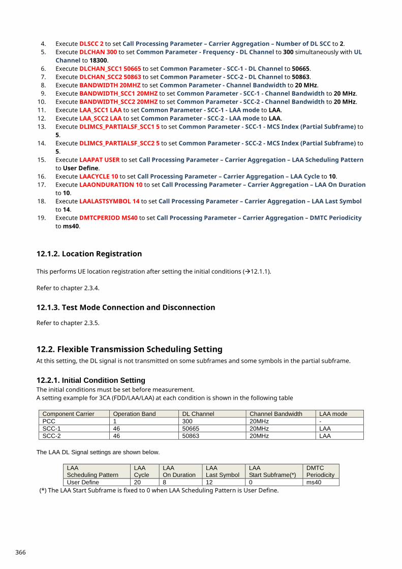
4. Execute DLSCC 2 to set Call Processing Parameter – Carrier Aggregation – Number of DL SCC to 2. 5. Execute DLCHAN 300 to set Common Parameter - Frequency - DL Channel to 300 simultaneously with UL
Channel to 18300. 6. Execute DLCHAN_SCC1 50665 to set Common Parameter - SCC-1 - DL Channel to 50665. 7. Execute DLCHAN_SCC2 50863 to set Common Parameter - SCC-2 - DL Channel to 50863. 8. Execute BANDWIDTH 20MHZ to set Common Parameter - Channel Bandwidth to 20 MHz. 9. Execute BANDWIDTH_SCC1 20MHZ to set Common Parameter - SCC-1 - Channel Bandwidth to 20 MHz.
10. Execute BANDWIDTH_SCC2 20MHZ to set Common Parameter - SCC-2 - Channel Bandwidth to 20 MHz. 11. Execute LAA_SCC1 LAA to set Common Parameter - SCC-1 - LAA mode to LAA. 12. Execute LAA_SCC2 LAA to set Common Parameter - SCC-2 - LAA mode to LAA. 13. Execute DLIMCS_PARTIALSF_SCC1 5 to set Common Parameter - SCC-1 - MCS Index (Partial Subframe) to
5. 14. Execute DLIMCS_PARTIALSF_SCC2 5 to set Common Parameter - SCC-2 - MCS Index (Partial Subframe) to
5. 15. Execute LAAPAT USER to set Call Processing Parameter – Carrier Aggregation – LAA Scheduling Pattern
to User Define. 16. Execute LAACYCLE 10 to set Call Processing Parameter – Carrier Aggregation – LAA Cycle to 10. 17. Execute LAAONDURATION 10 to set Call Processing Parameter – Carrier Aggregation – LAA On Duration
to 10. 18. Execute LAALASTSYMBOL 14 to set Call Processing Parameter – Carrier Aggregation – LAA Last Symbol
to 14. 19. Execute DMTCPERIOD MS40 to set Call Processing Parameter – Carrier Aggregation – DMTC Periodicity
to ms40.
Location Registration 12.1.2. This performs UE location registration after setting the initial conditions (12.1.1). Refer to chapter 2.3.4.
Test Mode Connection and Disconnection 12.1.3. Refer to chapter 2.3.5.
Flexible Transmission Scheduling Setting 12.2.At this setting, the DL signal is not transmitted on some subframes and some symbols in the partial subframe.
Initial Condition Setting 12.2.1.The initial conditions must be set before measurement. A setting example for 3CA (FDD/LAA/LAA) at each condition is shown in the following table
Component Carrier Operation Band DL Channel Channel Bandwidth LAA mode PCC 1 300 20MHz - SCC-1 46 50665 20MHz LAA SCC-2 46 50863 20MHz LAA
The LAA DL Signal settings are shown below.
LAA Scheduling Pattern
LAA Cycle
LAA On Duration
LAA Last Symbol
LAA Start Subframe(*)
DMTC Periodicity
User Define 20 8 12 0 ms40 (*) The LAA Start Subframe is fixed to 0 when LAA Scheduling Pattern is User Define.
366
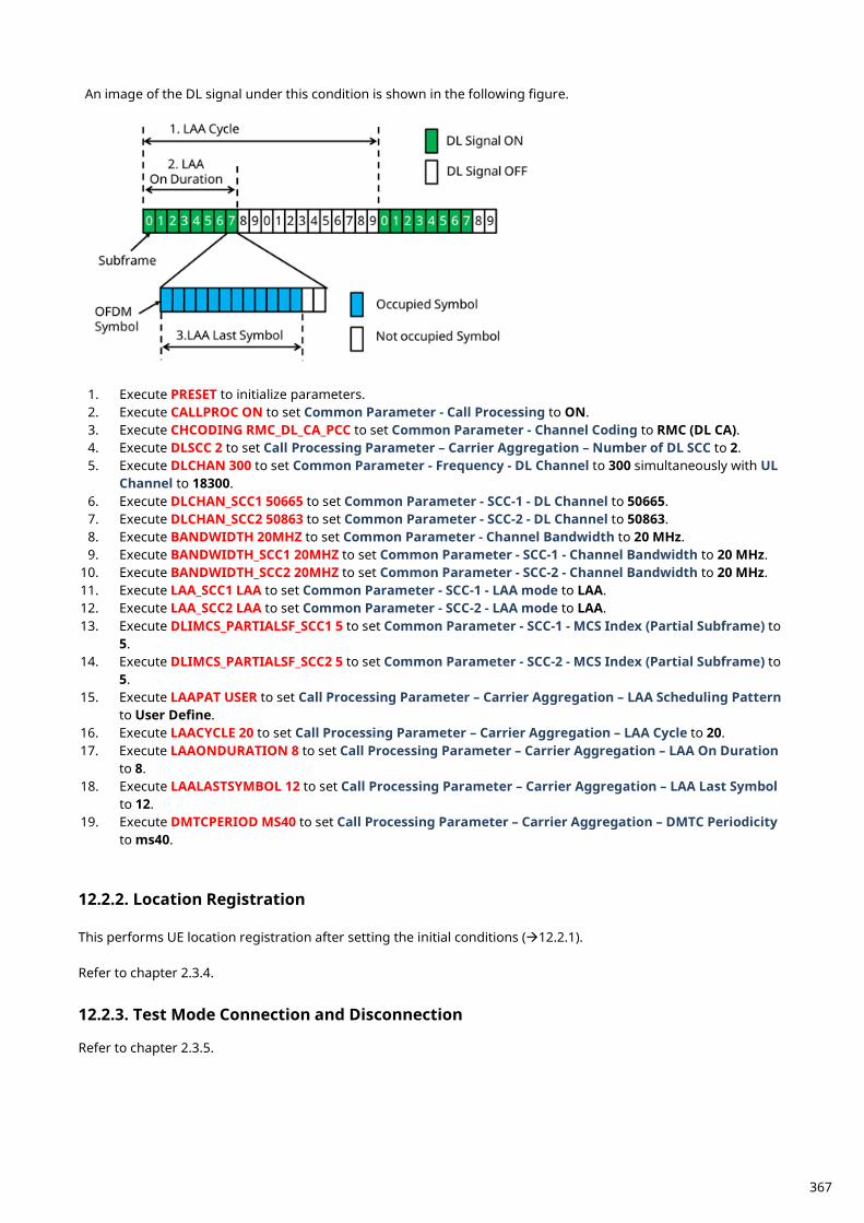
An image of the DL signal under this condition is shown in the following figure.
1. Execute PRESET to initialize parameters. 2. Execute CALLPROC ON to set Common Parameter - Call Processing to ON. 3. Execute CHCODING RMC_DL_CA_PCC to set Common Parameter - Channel Coding to RMC (DL CA). 4. Execute DLSCC 2 to set Call Processing Parameter – Carrier Aggregation – Number of DL SCC to 2. 5. Execute DLCHAN 300 to set Common Parameter - Frequency - DL Channel to 300 simultaneously with UL
Channel to 18300. 6. Execute DLCHAN_SCC1 50665 to set Common Parameter - SCC-1 - DL Channel to 50665. 7. Execute DLCHAN_SCC2 50863 to set Common Parameter - SCC-2 - DL Channel to 50863. 8. Execute BANDWIDTH 20MHZ to set Common Parameter - Channel Bandwidth to 20 MHz. 9. Execute BANDWIDTH_SCC1 20MHZ to set Common Parameter - SCC-1 - Channel Bandwidth to 20 MHz.
10. Execute BANDWIDTH_SCC2 20MHZ to set Common Parameter - SCC-2 - Channel Bandwidth to 20 MHz. 11. Execute LAA_SCC1 LAA to set Common Parameter - SCC-1 - LAA mode to LAA. 12. Execute LAA_SCC2 LAA to set Common Parameter - SCC-2 - LAA mode to LAA. 13. Execute DLIMCS_PARTIALSF_SCC1 5 to set Common Parameter - SCC-1 - MCS Index (Partial Subframe) to
5. 14. Execute DLIMCS_PARTIALSF_SCC2 5 to set Common Parameter - SCC-2 - MCS Index (Partial Subframe) to
5. 15. Execute LAAPAT USER to set Call Processing Parameter – Carrier Aggregation – LAA Scheduling Pattern
to User Define. 16. Execute LAACYCLE 20 to set Call Processing Parameter – Carrier Aggregation – LAA Cycle to 20. 17. Execute LAAONDURATION 8 to set Call Processing Parameter – Carrier Aggregation – LAA On Duration
to 8. 18. Execute LAALASTSYMBOL 12 to set Call Processing Parameter – Carrier Aggregation – LAA Last Symbol
to 12. 19. Execute DMTCPERIOD MS40 to set Call Processing Parameter – Carrier Aggregation – DMTC Periodicity
to ms40.
Location Registration 12.2.2. This performs UE location registration after setting the initial conditions (12.2.1). Refer to chapter 2.3.4.
Test Mode Connection and Disconnection 12.2.3. Refer to chapter 2.3.5.
367
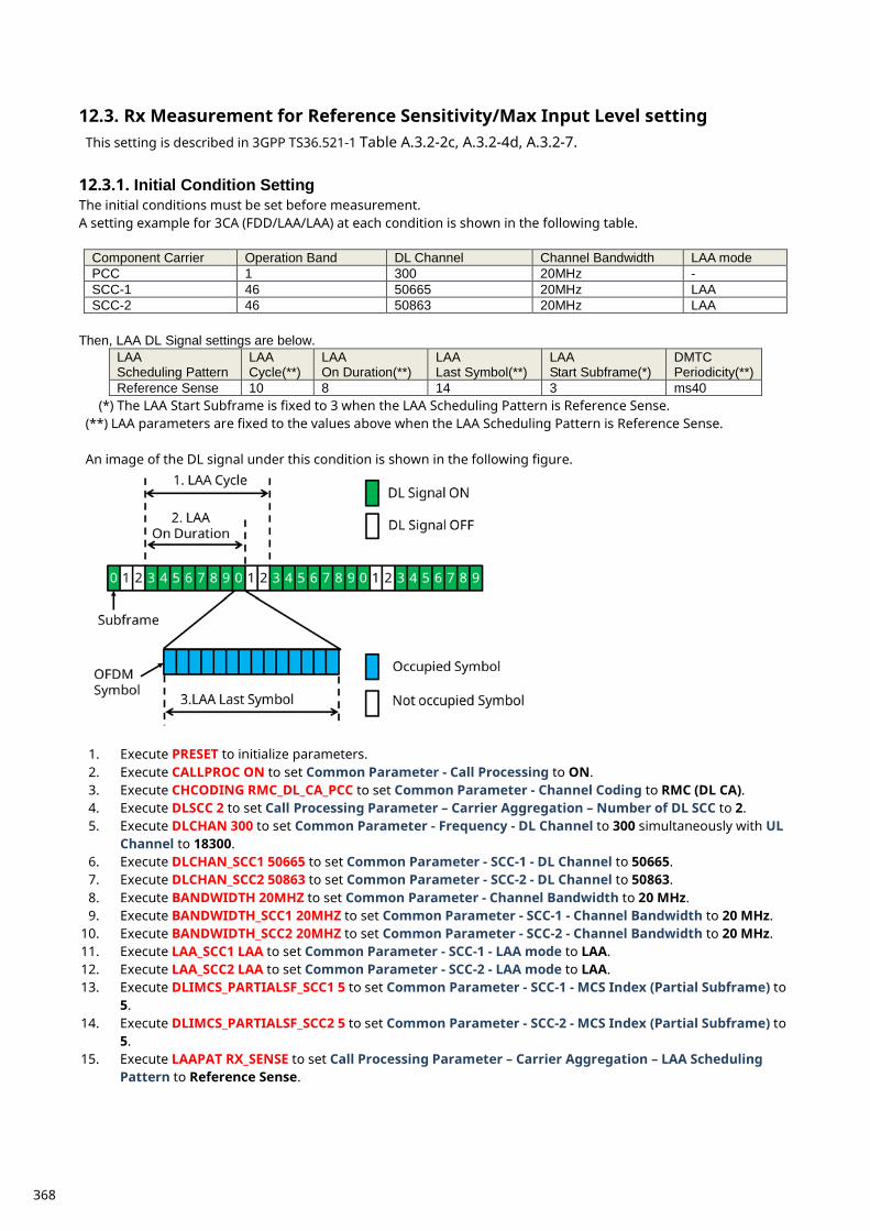
Rx Measurement for Reference Sensitivity/Max Input Level setting 12.3.This setting is described in 3GPP TS36.521-1 Table A.3.2-2c, A.3.2-4d, A.3.2-7.
Initial Condition Setting 12.3.1.The initial conditions must be set before measurement. A setting example for 3CA (FDD/LAA/LAA) at each condition is shown in the following table.
Component Carrier Operation Band DL Channel Channel Bandwidth LAA mode PCC 1 300 20MHz - SCC-1 46 50665 20MHz LAA SCC-2 46 50863 20MHz LAA
Then, LAA DL Signal settings are below.
LAA Scheduling Pattern
LAA Cycle(**)
LAA On Duration(**)
LAA Last Symbol(**)
LAA Start Subframe(*)
DMTC Periodicity(**)
Reference Sense 10 8 14 3 ms40 (*) The LAA Start Subframe is fixed to 3 when the LAA Scheduling Pattern is Reference Sense. (**) LAA parameters are fixed to the values above when the LAA Scheduling Pattern is Reference Sense. An image of the DL signal under this condition is shown in the following figure.
1. Execute PRESET to initialize parameters. 2. Execute CALLPROC ON to set Common Parameter - Call Processing to ON. 3. Execute CHCODING RMC_DL_CA_PCC to set Common Parameter - Channel Coding to RMC (DL CA). 4. Execute DLSCC 2 to set Call Processing Parameter – Carrier Aggregation – Number of DL SCC to 2. 5. Execute DLCHAN 300 to set Common Parameter - Frequency - DL Channel to 300 simultaneously with UL
Channel to 18300. 6. Execute DLCHAN_SCC1 50665 to set Common Parameter - SCC-1 - DL Channel to 50665. 7. Execute DLCHAN_SCC2 50863 to set Common Parameter - SCC-2 - DL Channel to 50863. 8. Execute BANDWIDTH 20MHZ to set Common Parameter - Channel Bandwidth to 20 MHz. 9. Execute BANDWIDTH_SCC1 20MHZ to set Common Parameter - SCC-1 - Channel Bandwidth to 20 MHz.
10. Execute BANDWIDTH_SCC2 20MHZ to set Common Parameter - SCC-2 - Channel Bandwidth to 20 MHz. 11. Execute LAA_SCC1 LAA to set Common Parameter - SCC-1 - LAA mode to LAA. 12. Execute LAA_SCC2 LAA to set Common Parameter - SCC-2 - LAA mode to LAA. 13. Execute DLIMCS_PARTIALSF_SCC1 5 to set Common Parameter - SCC-1 - MCS Index (Partial Subframe) to
5. 14. Execute DLIMCS_PARTIALSF_SCC2 5 to set Common Parameter - SCC-2 - MCS Index (Partial Subframe) to
5. 15. Execute LAAPAT RX_SENSE to set Call Processing Parameter – Carrier Aggregation – LAA Scheduling
Pattern to Reference Sense.
368

Location Registration 12.3.2. This performs UE location registration after setting the initial conditions (12.3.1). Refer to chapter 2.3.4.
Test Mode Connection and Disconnection 12.3.3. Refer to section 2.3.5.
369
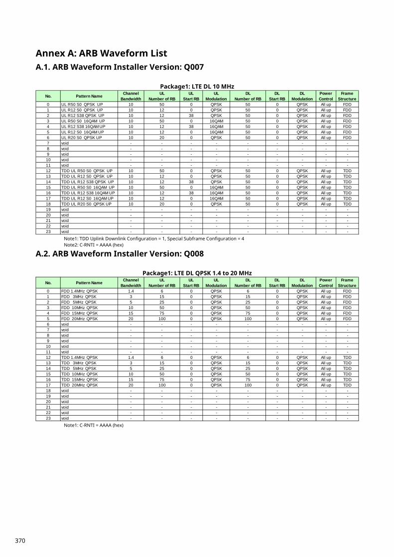
Annex A: ARB Waveform List A.1. ARB Waveform Installer Version: Q007
Package1: LTE DL 10 MHz
Note1: TDD Uplink Downlink Configuration = 1, Special Subframe Configuration = 4 Note2: C-RNTI = AAAA (hex)
A.2. ARB Waveform Installer Version: Q008
Package1: LTE DL QPSK 1.4 to 20 MHz
Note1: C-RNTI = AAAA (hex)
No. Pattern Name ChannelBandwidth
ULNumber of RB
ULStart RB
ULModulation
DLNumber of RB
DLStart RB
DLModulation
PowerControl
FrameStructure
0 UL R50 S0 QPSK UP 10 50 0 QPSK 50 0 QPSK All up FDD1 UL R12 S0 QPSK UP 10 12 0 QPSK 50 0 QPSK All up FDD2 UL R12 S38 QPSK UP 10 12 38 QPSK 50 0 QPSK All up FDD3 UL R50 S0 16QAM UP 10 50 0 16QAM 50 0 QPSK All up FDD4 UL R12 S38 16QAM UP 10 12 38 16QAM 50 0 QPSK All up FDD5 UL R12 S0 16QAM UP 10 12 0 16QAM 50 0 QPSK All up FDD6 UL R20 S0 QPSK UP 10 20 0 QPSK 50 0 QPSK All up FDD7 void - - - - - - - - -8 void - - - - - - - - -9 void - - - - - - - - -10 void - - - - - - - - -11 void - - - - - - - - -12 TDD UL R50 S0 QPSK UP 10 50 0 QPSK 50 0 QPSK All up TDD13 TDD UL R12 S0 QPSK UP 10 12 0 QPSK 50 0 QPSK All up TDD14 TDD UL R12 S38 QPSK UP 10 12 38 QPSK 50 0 QPSK All up TDD15 TDD UL R50 S0 16QAM UP 10 50 0 16QAM 50 0 QPSK All up TDD16 TDD UL R12 S38 16QAM UP 10 12 38 16QAM 50 0 QPSK All up TDD17 TDD UL R12 S0 16QAM UP 10 12 0 16QAM 50 0 QPSK All up TDD18 TDD UL R20 S0 QPSK UP 10 20 0 QPSK 50 0 QPSK All up TDD19 void - - - - - - - - -20 void - - - - - - - - -21 void - - - - - - - - -22 void - - - - - - - - -23 void - - - - - - - - -
No. Pattern Name ChannelBandwidth
ULNumber of RB
ULStart RB
ULModulation
DLNumber of RB
DLStart RB
DLModulation
PowerControl
FrameStructure
0 FDD 1.4MHz QPSK 1.4 6 0 QPSK 6 0 QPSK All up FDD1 FDD 3MHz QPSK 3 15 0 QPSK 15 0 QPSK All up FDD2 FDD 5MHz QPSK 5 25 0 QPSK 25 0 QPSK All up FDD3 FDD 10MHz QPSK 10 50 0 QPSK 50 0 QPSK All up FDD4 FDD 15MHz QPSK 15 75 0 QPSK 75 0 QPSK All up FDD5 FDD 20MHz QPSK 20 100 0 QPSK 100 0 QPSK All up FDD6 void - - - - - - - - -7 void - - - - - - - - -8 void - - - - - - - - -9 void - - - - - - - - -10 void - - - - - - - - -11 void - - - - - - - - -12 TDD 1.4MHz QPSK 1.4 6 0 QPSK 6 0 QPSK All up TDD13 TDD 3MHz QPSK 3 15 0 QPSK 15 0 QPSK All up TDD14 TDD 5MHz QPSK 5 25 0 QPSK 25 0 QPSK All up TDD15 TDD 10MHz QPSK 10 50 0 QPSK 50 0 QPSK All up TDD16 TDD 15MHz QPSK 15 75 0 QPSK 75 0 QPSK All up TDD17 TDD 20MHz QPSK 20 100 0 QPSK 100 0 QPSK All up TDD18 void - - - - - - - - -19 void - - - - - - - - -20 void - - - - - - - - -21 void - - - - - - - - -22 void - - - - - - - - -23 void - - - - - - - - -
370

Package2: LTE DL 64QAM 1.4 to 20 MHz
Note1: TDD Uplink Downlink Configuration = 1, Special Subframe Configuration = 4 Note2: C-RNTI = AAAA (hex)
No. Pattern Name ChannelBandwidth
ULNumber of RB
ULStart RB
ULModulation
DLNumber of RB
DLStart RB
DLModulation
PowerControl
FrameStructure
0 FDD 1.4MHz 64QAM 1.4 6 0 QPSK 6 0 64QAM All up FDD1 FDD 3MHz 64QAM 3 15 0 QPSK 15 0 64QAM All up FDD2 FDD 5MHz 64QAM 5 25 0 QPSK 25 0 64QAM All up FDD3 FDD 10MHz 64QAM 10 50 0 QPSK 50 0 64QAM All up FDD4 FDD 15MHz 64QAM 15 75 0 QPSK 75 0 64QAM All up FDD5 FDD 20MHz 64QAM 20 100 0 QPSK 100 0 64QAM All up FDD6 void - - - - - - - - -7 void - - - - - - - - -8 void - - - - - - - - -9 void - - - - - - - - -10 void - - - - - - - - -11 void - - - - - - - - -12 TDD 1.4MHz 64QAM 1.4 6 0 QPSK 6 0 64QAM All up TDD13 TDD 3MHz 64QAM 3 15 0 QPSK 15 0 64QAM All up TDD14 TDD 5MHz 64QAM 5 25 0 QPSK 25 0 64QAM All up TDD15 TDD 10MHz 64QAM 10 50 0 QPSK 50 0 64QAM All up TDD16 TDD 15MHz 64QAM 15 75 0 QPSK 75 0 64QAM All up TDD17 TDD 20MHz 64QAM 20 100 0 QPSK 100 0 64QAM All up TDD18 void - - - - - - - - -19 void - - - - - - - - -20 void - - - - - - - - -21 void - - - - - - - - -22 void - - - - - - - - -23 void - - - - - - - - -
371

Annex B: Informative B.1. UE DL-SCH RX It is important to consider the following settings when the UE is receiving using DL-SCH from the BTS (MT8821C).
UE Category Code Rate
B.1.1. UE Category TS36.306 defines the DL-SCH Rx performance as shown in the table below for each UE Category.
372
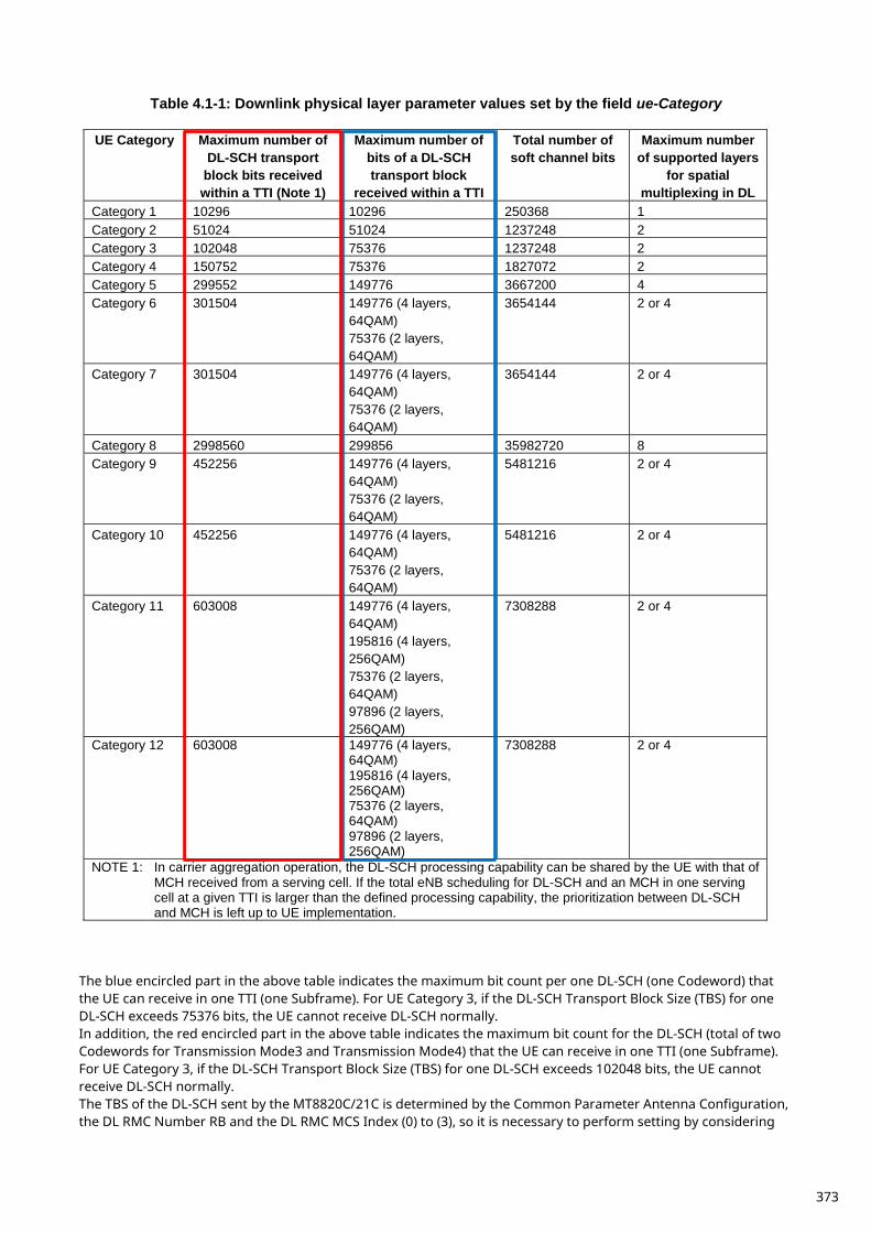
Table 4.1-1: Downlink physical layer parameter values set by the field ue-Category
UE Category Maximum number of DL-SCH transport
block bits received within a TTI (Note 1)
Maximum number of bits of a DL-SCH transport block
received within a TTI
Total number of soft channel bits
Maximum number of supported layers
for spatial multiplexing in DL
Category 1 10296 10296 250368 1 Category 2 51024 51024 1237248 2 Category 3 102048 75376 1237248 2 Category 4 150752 75376 1827072 2 Category 5 299552 149776 3667200 4 Category 6 301504 149776 (4 layers,
64QAM) 75376 (2 layers, 64QAM)
3654144 2 or 4
Category 7 301504 149776 (4 layers, 64QAM) 75376 (2 layers, 64QAM)
3654144 2 or 4
Category 8 2998560 299856 35982720 8 Category 9 452256 149776 (4 layers,
64QAM) 75376 (2 layers, 64QAM)
5481216 2 or 4
Category 10 452256 149776 (4 layers, 64QAM) 75376 (2 layers, 64QAM)
5481216 2 or 4
Category 11 603008 149776 (4 layers, 64QAM) 195816 (4 layers, 256QAM) 75376 (2 layers, 64QAM) 97896 (2 layers, 256QAM)
7308288 2 or 4
Category 12 603008 149776 (4 layers, 64QAM) 195816 (4 layers, 256QAM) 75376 (2 layers, 64QAM) 97896 (2 layers, 256QAM)
7308288 2 or 4
NOTE 1: In carrier aggregation operation, the DL-SCH processing capability can be shared by the UE with that of MCH received from a serving cell. If the total eNB scheduling for DL-SCH and an MCH in one serving cell at a given TTI is larger than the defined processing capability, the prioritization between DL-SCH and MCH is left up to UE implementation.
The blue encircled part in the above table indicates the maximum bit count per one DL-SCH (one Codeword) that the UE can receive in one TTI (one Subframe). For UE Category 3, if the DL-SCH Transport Block Size (TBS) for one DL-SCH exceeds 75376 bits, the UE cannot receive DL-SCH normally. In addition, the red encircled part in the above table indicates the maximum bit count for the DL-SCH (total of two Codewords for Transmission Mode3 and Transmission Mode4) that the UE can receive in one TTI (one Subframe). For UE Category 3, if the DL-SCH Transport Block Size (TBS) for one DL-SCH exceeds 102048 bits, the UE cannot receive DL-SCH normally. The TBS of the DL-SCH sent by the MT8820C/21C is determined by the Common Parameter Antenna Configuration, the DL RMC Number RB and the DL RMC MCS Index (0) to (3), so it is necessary to perform setting by considering
373
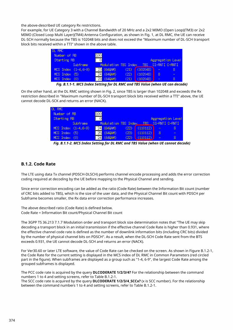
the above-described UE category Rx restrictions. For example, for UE Category 3 with a Channel Bandwidth of 20 MHz and a 2x2 MIMO (Open Loop)(TM3) or 2x2 MIMO (Closed Loop Multi Layer)(TM4) Antenna Configuration, as shown in Fig. 1, at DL RMC, the UE can receive DL-SCH normally because the TBS is 102048 bits and does not exceed the "Maximum number of DL-SCH transport block bits received within a TTI" shown in the above table.
Fig. B.1.1-1. MCS Index Setting for DL RMC and TBS Value (when UE can decode)
On the other hand, at the DL RMC setting shown in Fig. 2, since TBS is larger than 102048 and exceeds the Rx restriction described in "Maximum number of DL-SCH transport block bits received within a TTI" above, the UE cannot decode DL-SCK and returns an error (NACK).
Fig. B.1.1-2. MCS Index Setting for DL RMC and TBS Value (when UE cannot decode)
B.1.2. Code Rate The LTE using data Tx channel (PDSCH-DLSCH) performs channel encode processing and adds the error correction coding required at decoding by the UE before mapping to the Physical Channel and sending. Since error correction encoding can be added as the ratio (Code Rate) between the Information Bit count (number of CRC bits added to TBS), which is the size of the user data, and the Physical Channel Bit count with PDSCH per Subframe becomes smaller, the Rx data error correction performance increases. The above described ratio (Code Rate) is defined below. Code Rate = Information Bit count/Physical Channel Bit count The 3GPP TS 36.213 7.1.7 Modulation order and transport block size determination notes that "The UE may skip decoding a transport block in an initial transmission if the effective channel Code Rate is higher than 0.931, where the effective channel code rate is defined as the number of downlink information bits (including CRC bits) divided by the number of physical channel bits on PDSCH". As a result, when the DL-SCH Code Rate sent from the BTS exceeds 0.931, the UE cannot decode DL-SCH and returns an error (NACK). For Ver30.60 or later LTE software, the value of Code Rate can be checked on the screen. As shown in Figure B.1.2-1, the Code Rate for the current setting is displayed in the MCS index of DL RMC in Common Parameters (red circled part in the figure). When subframes are displayed as a group such as "1-4, 6-9", the largest Code Rate among the grouped subframes is displayed. The PCC code rate is acquired by the query DLCODERATE 1/2/3/4? For the relationship between the command numbers 1 to 4 and setting screens, refer to Table B.1.2-1. The SCC code rate is acquired by the query DLCODERATE 1/2/3/4_SCCx? (x is SCC number). For the relationship between the command numbers 1 to 4 and setting screens, refer to Table B.1.2-1.
374
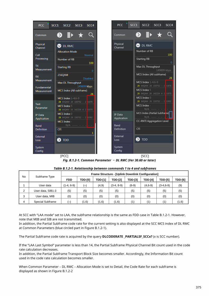
[PCC] [SCC]
Fig. B.1.2-1. Common Parameter – DL RMC (Ver 30.60 or later)
Table B.1.2-1. Relationship between commands 1 to 4 and subframes
No Subframe Type Frame Structure - [Uplink Downlink Configuration]
FDD TDD-[0] TDD-[1] TDD-[2] TDD-[3] TDD-[4] TDD-[5] TDD-[6]
1 User data (1-4, 6-9) (–) (4,9) (3-4, 8-9) (6-9) (4,6-9) (3-4,6-9) (9)
2 User data, SIB1-3 (5) (5) (5) (5) (5) (5) (5) (5)
3 User data, MIB (0) (0) (0) (0) (0) (0) (0) (0)
4 Special Subframe (–) (1,6) (1,6) (1,6) (1) (1) (1) (1,6)
At SCC with “LAA mode” set to LAA, the subframe relationship is the same as FDD case in Table B.1.2-1. However, note that MIB and SIB are not transmitted. In addition, the Partial Subframe code rate for the current setting is also displayed at the SCC MCS index of DL RMC at Common Parameters (blue circled part in Figure B.1.2-1). The Partial Subframe code rate is acquired by the query DLCODERATE _PARTIALSF_SCCx? (x is SCC number). If the “LAA Last Symbol” parameter is less than 14, the Partial Subframe Physical Channel Bit count used in the code rate calculation decreases. In addition, the Partial Subframe Transport Block Size becomes smaller. Accordingly, the Information Bit count used in the code rate calculation becomes smaller. When Common Parameter – DL RMC – Allocation Mode is set to Detail, the Code Rate for each subframe is displayed as shown in Figure B.1.2-2
375
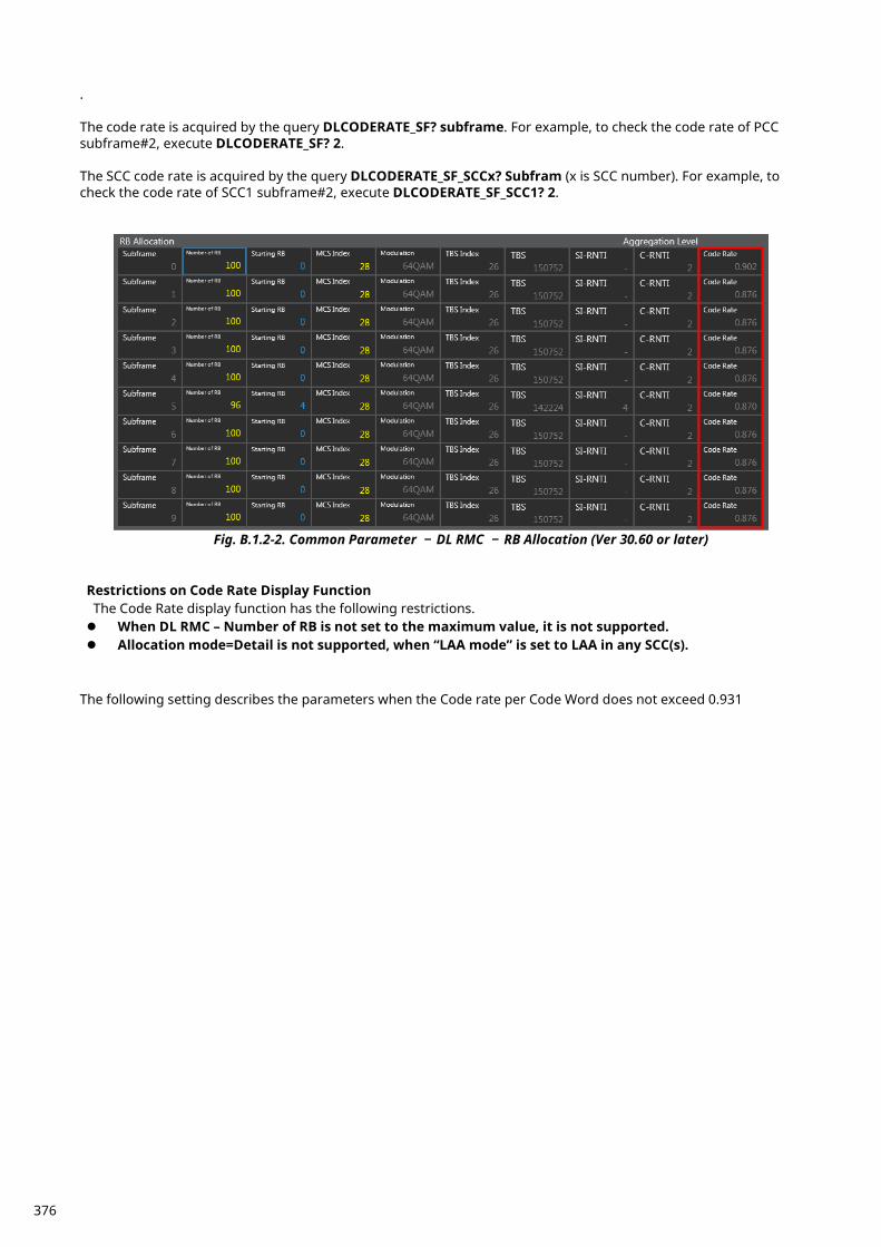
. The code rate is acquired by the query DLCODERATE_SF? subframe. For example, to check the code rate of PCC subframe#2, execute DLCODERATE_SF? 2. The SCC code rate is acquired by the query DLCODERATE_SF_SCCx? Subfram (x is SCC number). For example, to check the code rate of SCC1 subframe#2, execute DLCODERATE_SF_SCC1? 2.
Fig. B.1.2-2. Common Parameter – DL RMC – RB Allocation (Ver 30.60 or later)
Restrictions on Code Rate Display Function The Code Rate display function has the following restrictions. When DL RMC – Number of RB is not set to the maximum value, it is not supported. Allocation mode=Detail is not supported, when “LAA mode” is set to LAA in any SCC(s).
The following setting describes the parameters when the Code rate per Code Word does not exceed 0.931
376
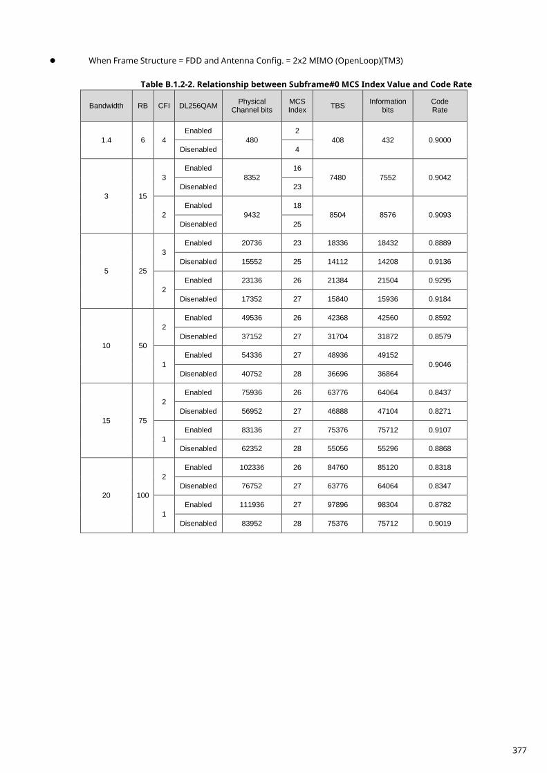
When Frame Structure = FDD and Antenna Config. = 2x2 MIMO (OpenLoop)(TM3)
Table B.1.2-2. Relationship between Subframe#0 MCS Index Value and Code Rate
Bandwidth RB CFI DL256QAM Physical Channel bits
MCS Index TBS Information
bits Code Rate
1.4 6 4 Enabled
480 2
408 432 0.9000 Disenabled 4
3 15
3 Enabled
8352 16
7480 7552 0.9042 Disenabled 23
2 Enabled
9432 18
8504 8576 0.9093 Disenabled 25
5 25
3 Enabled 20736 23 18336 18432 0.8889
Disenabled 15552 25 14112 14208 0.9136
2 Enabled 23136 26 21384 21504 0.9295
Disenabled 17352 27 15840 15936 0.9184
10 50
2 Enabled 49536 26 42368 42560 0.8592
Disenabled 37152 27 31704 31872 0.8579
1 Enabled 54336 27 48936 49152
0.9046 Disenabled 40752 28 36696 36864
15 75
2 Enabled 75936 26 63776 64064 0.8437
Disenabled 56952 27 46888 47104 0.8271
1 Enabled 83136 27 75376 75712 0.9107
Disenabled 62352 28 55056 55296 0.8868
20 100
2 Enabled 102336 26 84760 85120 0.8318
Disenabled 76752 27 63776 64064 0.8347
1 Enabled 111936 27 97896 98304 0.8782
Disenabled 83952 28 75376 75712 0.9019
377
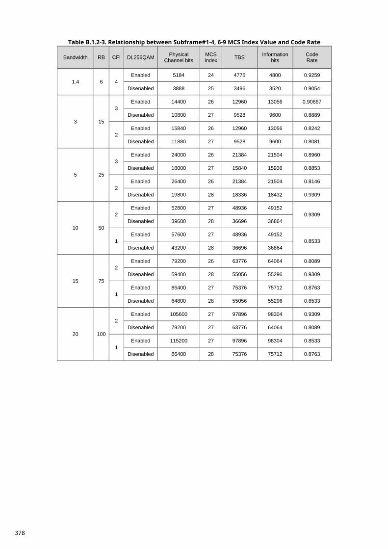
Table B.1.2-3. Relationship between Subframe#1-4, 6-9 MCS Index Value and Code Rate
Bandwidth RB CFI DL256QAM Physical Channel bits
MCS Index TBS Information
bits Code Rate
1.4 6 4 Enabled 5184 24 4776 4800 0.9259
Disenabled 3888 25 3496 3520 0.9054
3 15
3 Enabled 14400 26 12960 13056 0.90667
Disenabled 10800 27 9528 9600 0.8889
2 Enabled 15840 26 12960 13056 0.8242
Disenabled 11880 27 9528 9600 0.8081
5 25
3 Enabled 24000 26 21384 21504 0.8960
Disenabled 18000 27 15840 15936 0.8853
2 Enabled 26400 26 21384 21504 0.8146
Disenabled 19800 28 18336 18432 0.9309
10 50
2 Enabled 52800 27 48936 49152
0.9309 Disenabled 39600 28 36696 36864
1 Enabled 57600 27 48936 49152
0.8533 Disenabled 43200 28 36696 36864
15 75
2 Enabled 79200 26 63776 64064 0.8089
Disenabled 59400 28 55056 55296 0.9309
1 Enabled 86400 27 75376 75712 0.8763
Disenabled 64800 28 55056 55296 0.8533
20 100
2 Enabled 105600 27 97896 98304 0.9309
Disenabled 79200 27 63776 64064 0.8089
1 Enabled 115200 27 97896 98304 0.8533
Disenabled 86400 28 75376 75712 0.8763
378
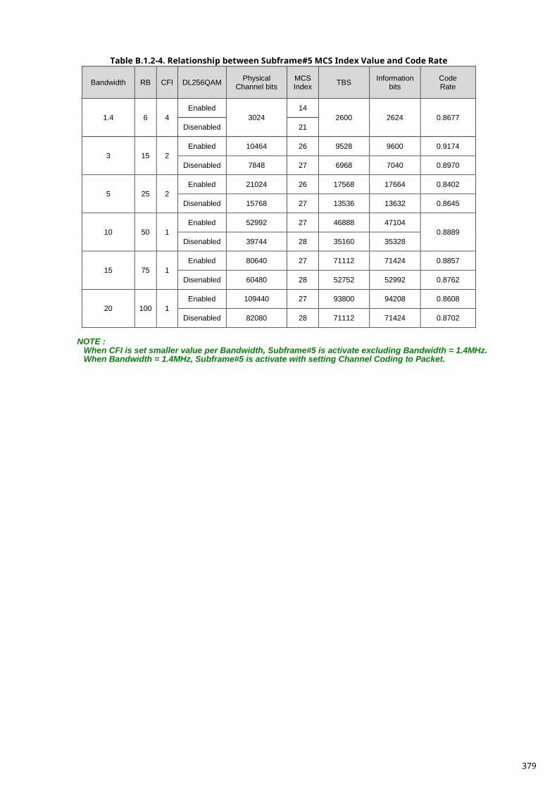
Table B.1.2-4. Relationship between Subframe#5 MCS Index Value and Code Rate
Bandwidth RB CFI DL256QAM Physical Channel bits
MCS Index TBS Information
bits Code Rate
1.4 6 4 Enabled
3024 14
2600 2624 0.8677 Disenabled 21
3 15 2 Enabled 10464 26 9528 9600 0.9174
Disenabled 7848 27 6968 7040 0.8970
5 25 2 Enabled 21024 26 17568 17664 0.8402
Disenabled 15768 27 13536 13632 0.8645
10 50 1 Enabled 52992 27 46888 47104
0.8889 Disenabled 39744 28 35160 35328
15 75 1 Enabled 80640 27 71112 71424 0.8857
Disenabled 60480 28 52752 52992 0.8762
20 100 1 Enabled 109440 27 93800 94208 0.8608
Disenabled 82080 28 71112 71424 0.8702
NOTE :
When CFI is set smaller value per Bandwidth, Subframe#5 is activate excluding Bandwidth = 1.4MHz. When Bandwidth = 1.4MHz, Subframe#5 is activate with setting Channel Coding to Packet.
379
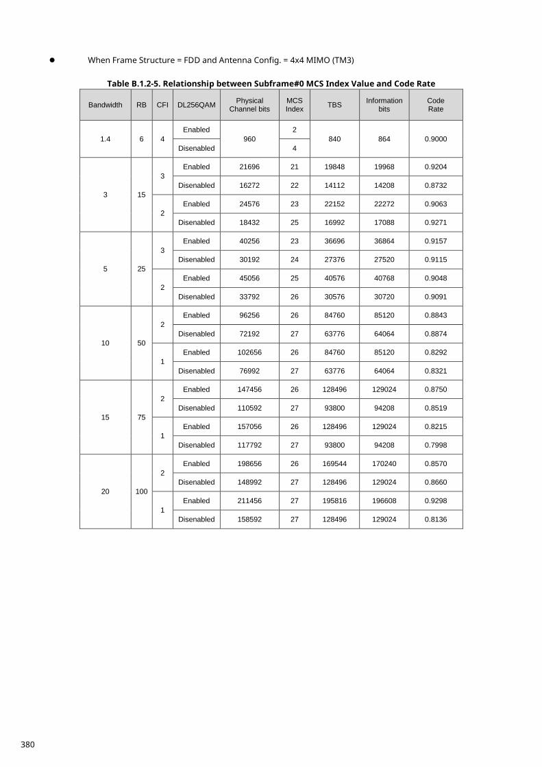
When Frame Structure = FDD and Antenna Config. = 4x4 MIMO (TM3)
Table B.1.2-5. Relationship between Subframe#0 MCS Index Value and Code Rate
Bandwidth RB CFI DL256QAM Physical Channel bits
MCS Index TBS Information
bits Code Rate
1.4 6 4 Enabled
960 2
840 864 0.9000 Disenabled 4
3 15
3 Enabled 21696 21 19848 19968 0.9204
Disenabled 16272 22 14112 14208 0.8732
2 Enabled 24576 23 22152 22272 0.9063
Disenabled 18432 25 16992 17088 0.9271
5 25
3 Enabled 40256 23 36696 36864 0.9157
Disenabled 30192 24 27376 27520 0.9115
2 Enabled 45056 25 40576 40768 0.9048
Disenabled 33792 26 30576 30720 0.9091
10 50
2 Enabled 96256 26 84760 85120 0.8843
Disenabled 72192 27 63776 64064 0.8874
1 Enabled 102656 26 84760 85120 0.8292
Disenabled 76992 27 63776 64064 0.8321
15 75
2 Enabled 147456 26 128496 129024 0.8750
Disenabled 110592 27 93800 94208 0.8519
1 Enabled 157056 26 128496 129024 0.8215
Disenabled 117792 27 93800 94208 0.7998
20 100
2 Enabled 198656 26 169544 170240 0.8570
Disenabled 148992 27 128496 129024 0.8660
1 Enabled 211456 27 195816 196608 0.9298
Disenabled 158592 27 128496 129024 0.8136
380
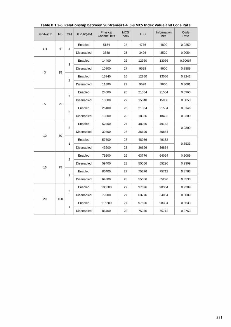
Table B.1.2-6. Relationship between Subframe#1-4 ,6-9 MCS Index Value and Code Rate
Bandwidth RB CFI DL256QAM Physical Channel bits
MCS Index TBS Information
bits Code Rate
1.4 6 4 Enabled 5184 24 4776 4800 0.9259
Disenabled 3888 25 3496 3520 0.9054
3 15
3 Enabled 14400 26 12960 13056 0.90667
Disenabled 10800 27 9528 9600 0.8889
2 Enabled 15840 26 12960 13056 0.8242
Disenabled 11880 27 9528 9600 0.8081
5 25
3 Enabled 24000 26 21384 21504 0.8960
Disenabled 18000 27 15840 15936 0.8853
2 Enabled 26400 26 21384 21504 0.8146
Disenabled 19800 28 18336 18432 0.9309
10 50
2 Enabled 52800 27 48936 49152
0.9309 Disenabled 39600 28 36696 36864
1 Enabled 57600 27 48936 49152
0.8533 Disenabled 43200 28 36696 36864
15 75
2 Enabled 79200 26 63776 64064 0.8089
Disenabled 59400 28 55056 55296 0.9309
1 Enabled 86400 27 75376 75712 0.8763
Disenabled 64800 28 55056 55296 0.8533
20 100
2 Enabled 105600 27 97896 98304 0.9309
Disenabled 79200 27 63776 64064 0.8089
1 Enabled 115200 27 97896 98304 0.8533
Disenabled 86400 28 75376 75712 0.8763
381
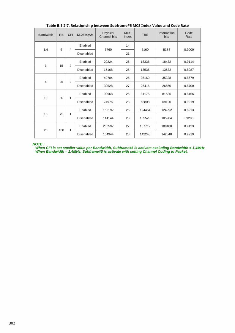
Table B.1.2-7. Relationship between Subframe#5 MCS Index Value and Code Rate
Bandwidth RB CFI DL256QAM Physical Channel bits
MCS Index TBS Information
bits Code Rate
1.4 6 4 Enabled
5760 14
5160 5184 0.9000 Disenabled 21
3 15 2 Enabled 20224 25 18336 18432 0.9114
Disenabled 15168 26 13536 13632 0.8987
5 25 2 Enabled 40704 26 35160 35328 0.8679
Disenabled 30528 27 26416 26560 0.8700
10 50 1 Enabled 99968 26 81176 81536 0.8156
Disenabled 74976 28 68808 69120 0.9219
15 75 1 Enabled 152192 26 124464 124992 0.8213
Disenabled 114144 28 105528 105984 09285
20 100 1 Enabled 206592 27 187712 188480 0.9123
Disenabled 154944 28 142248 142848 0.9219
NOTE :
When CFI is set smaller value per Bandwidth, Subframe#5 is activate excluding Bandwidth = 1.4MHz. When Bandwidth = 1.4MHz, Subframe#5 is activate with setting Channel Coding to Packet.
382
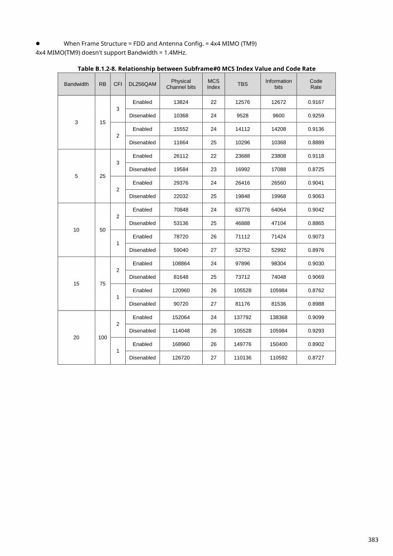
When Frame Structure = FDD and Antenna Config. = 4x4 MIMO (TM9) 4x4 MIMO(TM9) doesn't support Bandwidth = 1.4MHz.
Table B.1.2-8. Relationship between Subframe#0 MCS Index Value and Code Rate
Bandwidth RB CFI DL256QAM Physical Channel bits
MCS Index TBS Information
bits Code Rate
3 15
3 Enabled 13824 22 12576 12672 0.9167
Disenabled 10368 24 9528 9600 0.9259
2 Enabled 15552 24 14112 14208 0.9136
Disenabled 11664 25 10296 10368 0.8889
5 25
3 Enabled 26112 22 23688 23808 0.9118
Disenabled 19584 23 16992 17088 0.8725
2 Enabled 29376 24 26416 26560 0.9041
Disenabled 22032 25 19848 19968 0.9063
10 50
2 Enabled 70848 24 63776 64064 0.9042
Disenabled 53136 25 46888 47104 0.8865
1 Enabled 78720 26 71112 71424 0.9073
Disenabled 59040 27 52752 52992 0.8976
15 75
2 Enabled 108864 24 97896 98304 0.9030
Disenabled 81648 25 73712 74048 0.9069
1 Enabled 120960 26 105528 105984 0.8762
Disenabled 90720 27 81176 81536 0.8988
20 100
2 Enabled 152064 24 137792 138368 0.9099
Disenabled 114048 26 105528 105984 0.9293
1 Enabled 168960 26 149776 150400 0.8902
Disenabled 126720 27 110136 110592 0.8727
383
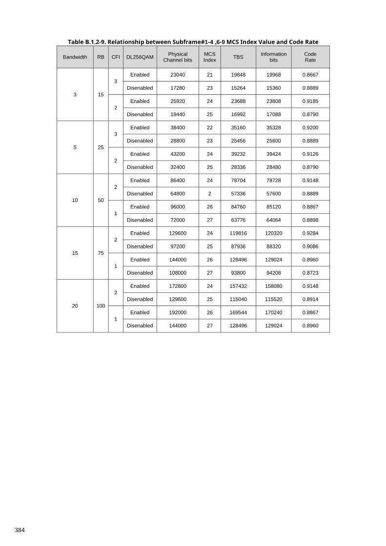
Table B.1.2-9. Relationship between Subframe#1-4 ,6-9 MCS Index Value and Code Rate
Bandwidth RB CFI DL256QAM Physical Channel bits
MCS Index TBS Information
bits Code Rate
3 15
3 Enabled 23040 21 19848 19968 0.8667
Disenabled 17280 23 15264 15360 0.8889
2 Enabled 25920 24 23688 23808 0.9185
Disenabled 19440 25 16992 17088 0.8790
5 25
3 Enabled 38400 22 35160 35328 0.9200
Disenabled 28800 23 25456 25600 0.8889
2 Enabled 43200 24 39232 39424 0.9126
Disenabled 32400 25 28336 28480 0.8790
10 50
2 Enabled 86400 24 78704 78728 0.9148
Disenabled 64800 2 57336 57600 0.8889
1 Enabled 96000 26 84760 85120 0.8867
Disenabled 72000 27 63776 64064 0.8898
15 75
2 Enabled 129600 24 119816 120320 0.9284
Disenabled 97200 25 87936 88320 0.9086
1 Enabled 144000 26 128496 129024 0.8960
Disenabled 108000 27 93800 94208 0.8723
20 100
2 Enabled 172800 24 157432 158080 0.9148
Disenabled 129600 25 115040 115520 0.8914
1 Enabled 192000 26 169544 170240 0.8867
Disenabled 144000 27 128496 129024 0.8960
384
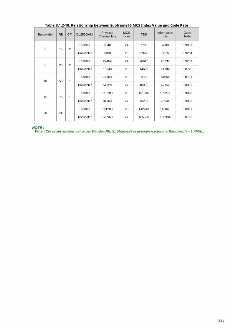
Table B.1.2-10. Relationship between Subframe#5 MCS Index Value and Code Rate
Bandwidth RB CFI DL256QAM Physical Channel bits
MCS Index TBS Information
bits Code Rate
3 15 2 Enabled 8640 24 7736 7808 0.9037
Disenabled 6480 26 5992 6016 0.9284
5 25 2 Enabled 22464 24 20616 20736 0.9231
Disenabled 16848 25 14688 14784 0.8775
10 50 1 Enabled 72960 26 63776 64064 0.8781
Disenabled 54720 27 48936 49152 0.8982
15 75 1 Enabled 113280 26 101840 102272 0.9028
Disenabled 84960 27 76208 76544 0.9009
20 100 1 Enabled 161280 26 142248 142848 0.8857
Disenabled 120960 27 105528 105984 0.8762
NOTE :
When CFI is set smaller value per Bandwidth, Subframe#5 is activate excluding Bandwidth = 1.4MHz.
385
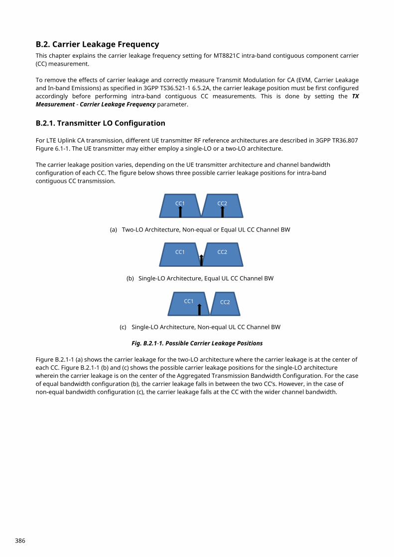
B.2. Carrier Leakage Frequency This chapter explains the carrier leakage frequency setting for MT8821C intra-band contiguous component carrier (CC) measurement. To remove the effects of carrier leakage and correctly measure Transmit Modulation for CA (EVM, Carrier Leakage and In-band Emissions) as specified in 3GPP TS36.521-1 6.5.2A, the carrier leakage position must be first configured accordingly before performing intra-band contiguous CC measurements. This is done by setting the TX Measurement - Carrier Leakage Frequency parameter.
B.2.1. Transmitter LO Configuration For LTE Uplink CA transmission, different UE transmitter RF reference architectures are described in 3GPP TR36.807 Figure 6.1-1. The UE transmitter may either employ a single-LO or a two-LO architecture. The carrier leakage position varies, depending on the UE transmitter architecture and channel bandwidth configuration of each CC. The figure below shows three possible carrier leakage positions for intra-band contiguous CC transmission.
(a) Two-LO Architecture, Non-equal or Equal UL CC Channel BW
(b) Single-LO Architecture, Equal UL CC Channel BW
(c) Single-LO Architecture, Non-equal UL CC Channel BW
Fig. B.2.1-1. Possible Carrier Leakage Positions
Figure B.2.1-1 (a) shows the carrier leakage for the two-LO architecture where the carrier leakage is at the center of each CC. Figure B.2.1-1 (b) and (c) shows the possible carrier leakage positions for the single-LO architecture wherein the carrier leakage is on the center of the Aggregated Transmission Bandwidth Configuration. For the case of equal bandwidth configuration (b), the carrier leakage falls in between the two CC’s. However, in the case of non-equal bandwidth configuration (c), the carrier leakage falls at the CC with the wider channel bandwidth.
CC1 CC2
CC1 CC2
CC1 CC2
386
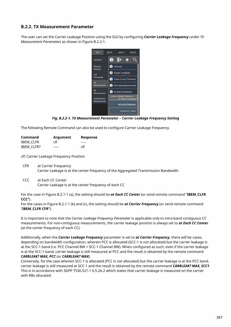
B.2.2. TX Measurement Parameter The user can set the Carrier Leakage Position using the GUI by configuring Carrier Leakage Frequency under TX Measurement Parameters as shown in Figure B.2.2-1.
Fig. B.2.2-1. TX Measurement Parameter – Carrier Leakage Frequency Setting
The following Remote Command can also be used to configure Carrier Leakage Frequency. Command Argument Response IBEM_CLFR clf ----- IBEM_CLFR? ----- clf clf: Carrier Leakage Frequency Position CFR at Carrier Frequency
Carrier Leakage is at the center frequency of the Aggregated Transmission Bandwidth CCC at Each CC Center Carrier Leakage is at the center frequency of each CC
For the case in Figure B.2.1-1 (a), the setting should be at Each CC Center (or send remote command “IBEM_CLFR CCC”). For the cases in Figure B.2.1-1 (b) and (c), the setting should be at Carrier Frequency (or send remote command “IBEM_CLFR CFR”). It is important to note that the Carrier Leakage Frequency Parameter is applicable only to intra-band contiguous CC measurements. For non-contiguous measurements, the carrier leakage position is always set to at Each CC Center (at the center frequency of each CC). Additionally, when the Carrier Leakage Frequency parameter is set to at Carrier Frequency, there will be cases, depending on bandwidth configuration, wherein PCC is allocated (SCC-1 is not allocated) but the carrier leakage is at the SCC-1 band (i.e. PCC Channel BW < SCC-1 Channel BW). When configured as such, even if the carrier leakage is at the SCC-1 band, carrier leakage is still measured at PCC and the result is obtained by the remote command CARRLEAK? MAX, PCC (or CARRLEAK? MAX). Conversely, for the case wherein SCC-1 is allocated (PCC is not allocated) but the carrier leakage is at the PCC band, carrier leakage is still measured at SCC-1 and the result is obtained by the remote command CARRLEAK? MAX, SCC1. This is in accordance with 3GPP TS36.521-1 6.5.2A.2 which states that carrier leakage is measured on the carrier with RBs allocated.
387
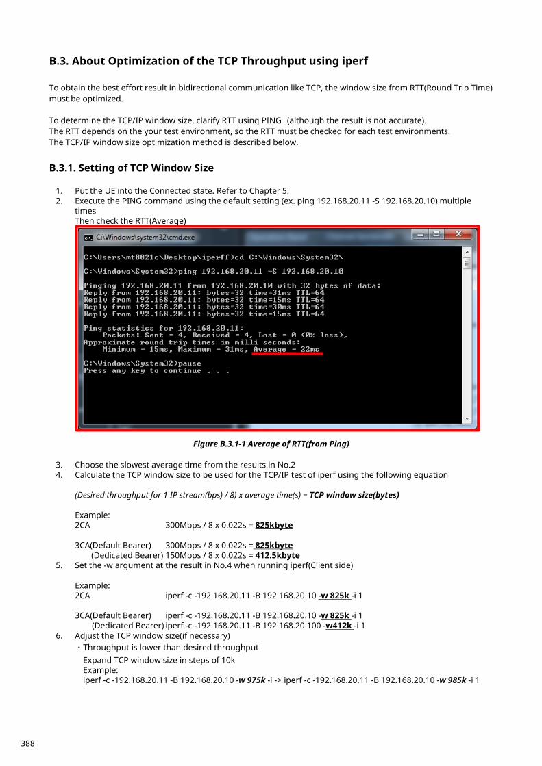
B.3. About Optimization of the TCP Throughput using iperf To obtain the best effort result in bidirectional communication like TCP, the window size from RTT(Round Trip Time) must be optimized. To determine the TCP/IP window size, clarify RTT using PING (although the result is not accurate). The RTT depends on the your test environment, so the RTT must be checked for each test environments. The TCP/IP window size optimization method is described below.
B.3.1. Setting of TCP Window Size
1. Put the UE into the Connected state. Refer to Chapter 5. 2. Execute the PING command using the default setting (ex. ping 192.168.20.11 -S 192.168.20.10) multiple
times Then check the RTT(Average)
Figure B.3.1-1 Average of RTT(from Ping)
3. Choose the slowest average time from the results in No.2 4. Calculate the TCP window size to be used for the TCP/IP test of iperf using the following equation
(Desired throughput for 1 IP stream(bps) / 8) x average time(s) = TCP window size(bytes) Example: 2CA 300Mbps / 8 x 0.022s = 825kbyte 3CA(Default Bearer) 300Mbps / 8 x 0.022s = 825kbyte (Dedicated Bearer) 150Mbps / 8 x 0.022s = 412.5kbyte
5. Set the -w argument at the result in No.4 when running iperf(Client side) Example: 2CA iperf -c -192.168.20.11 -B 192.168.20.10 -w 825k -i 1 3CA(Default Bearer) iperf -c -192.168.20.11 -B 192.168.20.10 -w 825k -i 1 (Dedicated Bearer) iperf -c -192.168.20.11 -B 192.168.20.100 -w412k -i 1
6. Adjust the TCP window size(if necessary) ・Throughput is lower than desired throughput Expand TCP window size in steps of 10k Example: iperf -c -192.168.20.11 -B 192.168.20.10 -w 975k -i -> iperf -c -192.168.20.11 -B 192.168.20.10 -w 985k -i 1
388

・Throughput is unstable(This situation, TCP window size too large) Reduce TCP window size in steps of 10k Example: iperf -c -192.168.20.11 -B 192.168.20.10 -w 975k -i -> iperf -c -192.168.20.11 -B 192.168.20.10 -w 965k -i 1
389
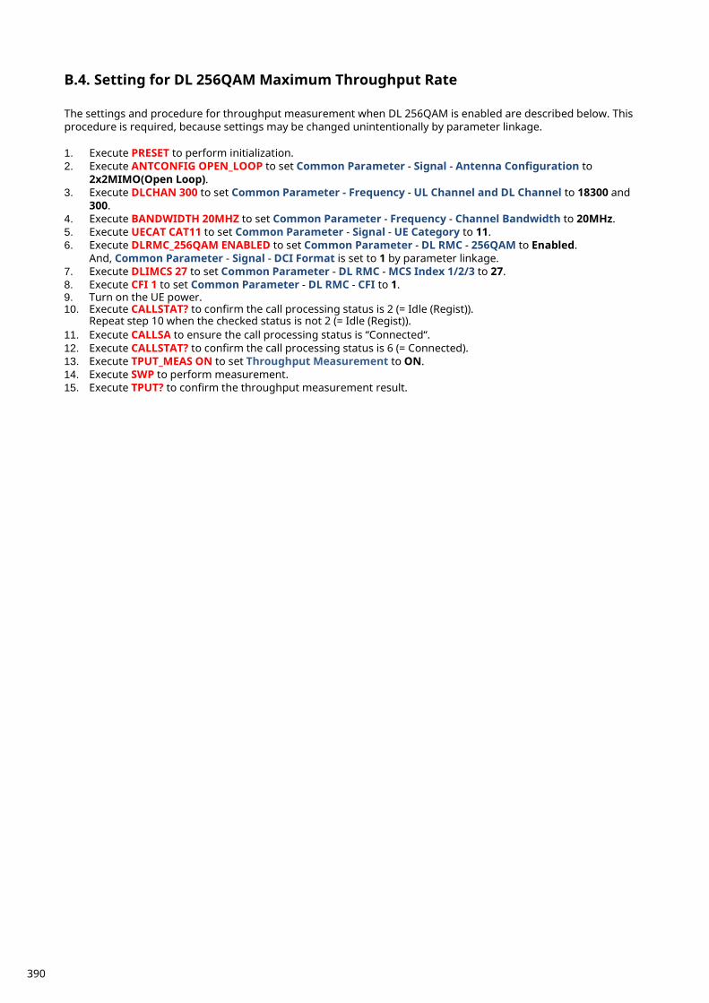
B.4. Setting for DL 256QAM Maximum Throughput Rate The settings and procedure for throughput measurement when DL 256QAM is enabled are described below. This procedure is required, because settings may be changed unintentionally by parameter linkage. 1. Execute PRESET to perform initialization. 2. Execute ANTCONFIG OPEN_LOOP to set Common Parameter - Signal - Antenna Configuration to
2x2MIMO(Open Loop). 3. Execute DLCHAN 300 to set Common Parameter - Frequency - UL Channel and DL Channel to 18300 and
300. 4. Execute BANDWIDTH 20MHZ to set Common Parameter - Frequency - Channel Bandwidth to 20MHz. 5. Execute UECAT CAT11 to set Common Parameter - Signal - UE Category to 11. 6. Execute DLRMC_256QAM ENABLED to set Common Parameter - DL RMC - 256QAM to Enabled.
And, Common Parameter - Signal - DCI Format is set to 1 by parameter linkage. 7. Execute DLIMCS 27 to set Common Parameter - DL RMC - MCS Index 1/2/3 to 27. 8. Execute CFI 1 to set Common Parameter - DL RMC - CFI to 1. 9. Turn on the UE power. 10. Execute CALLSTAT? to confirm the call processing status is 2 (= Idle (Regist)).
Repeat step 10 when the checked status is not 2 (= Idle (Regist)). 11. Execute CALLSA to ensure the call processing status is “Connected“. 12. Execute CALLSTAT? to confirm the call processing status is 6 (= Connected). 13. Execute TPUT_MEAS ON to set Throughput Measurement to ON. 14. Execute SWP to perform measurement. 15. Execute TPUT? to confirm the throughput measurement result.
390
Anritsu Company 1155 East Collins Blvd., Suite 100, Richardson, TX 75081, U.S.A.Toll Free: 1-800-267-4878Phone: +1-972-644-1777Fax: +1-972-671-1877
• CanadaAnritsu Electronics Ltd.700 Silver Seven Road, Suite 120, Kanata, Ontario K2V 1C3, CanadaPhone: +1-613-591-2003 Fax: +1-613-591-1006
• Brazil Anritsu Eletronica Ltda.
Phone: +55-11-3283-2511Fax: +55-11-3288-6940
• MexicoAnritsu Company, S.A. de C.V.Av. Ejército Nacional No. 579 Piso 9, Col. Granada11520 México, D.F., MéxicoPhone: +52-55-1101-2370Fax: +52-55-5254-3147
• United KingdomAnritsu EMEA Ltd. 200 Capability Green, Luton, Bedfordshire, LU1 3LU, U.K.Phone: +44-1582-433200 Fax: +44-1582-731303
• FranceAnritsu S.A. 12 avenue du Québec, Bâtiment Iris 1- Silic 612,91140 VILLEBON SUR YVETTE, FrancePhone: +33-1-60-92-15-50Fax: +33-1-64-46-10-65
• GermanyAnritsu GmbHNemetschek Haus, Konrad-Zuse-Platz 1 81829 München, Germany Phone: +49-89-442308-0Fax: +49-89-442308-55
• ItalyAnritsu S.r.l.Via Elio Vittorini 129, 00144 Roma, ItalyPhone: +39-6-509-9711 Fax: +39-6-502-2425
• SwedenAnritsu ABKistagången 20B, 164 40 KISTA, SwedenPhone: +46-8-534-707-00Fax: +46-8-534-707-30
• FinlandAnritsu ABTeknobulevardi 3-5, FI-01530 VANTAA, FinlandPhone: +358-20-741-8100Fax: +358-20-741-8111
• DenmarkAnritsu A/STorveporten 2, 2500 Valby, DenmarkPhone: +45-7211-2200Fax: +45-7211-2210
• RussiaAnritsu EMEA Ltd. Representation Office in RussiaTverskaya str. 16/2, bld. 1, 7th floor.Moscow, 125009, RussiaPhone: +7-495-363-1694Fax: +7-495-935-8962
• SpainAnritsu EMEA Ltd.Representation Office in SpainEdificio Cuzco IV, Po. de la Castellana, 141, Pta. 528046, Madrid, SpainPhone: +34-915-726-761Fax: +34-915-726-621
• United Arab EmiratesAnritsu EMEA Ltd. Dubai Liaison Office
• P.R. China (Shanghai)Anritsu (China) Co., Ltd.Room 2701-2705, Tower A, New Caohejing International Business CenterNo. 391 Gui Ping Road Shanghai, 200233, P.R. ChinaPhone: +86-21-6237-0898Fax: +86-21-6237-0899
• P.R. China (Hong Kong)Anritsu Company Ltd.Unit 1006-7, 10/F., Greenfield Tower, Concordia Plaza,No. 1 Science Museum Road, Tsim Sha Tsui East, Kowloon, Hong Kong, P.R. ChinaPhone: +852-2301-4980Fax: +852-2301-3545
• JapanAnritsu Corporation
Phone: +81-46-296-6509Fax: +81-46-225-8352
8-5, Tamura-cho, Atsugi-shi, Kanagawa, 243-0016 Japan
• KoreaAnritsu Corporation, Ltd.5FL, 235 Pangyoyeok-ro, Bundang-gu, Seongnam-si, Gyeonggi-do, 13494 KoreaPhone: +82-31-696-7750Fax: +82-31-696-7751
• AustraliaAnritsu Pty. Ltd.
Phone: +61-3-9558-8177Fax: +61-3-9558-8255
• TaiwanAnritsu Company Inc.7F, No. 316, Sec. 1, NeiHu Rd., Taipei 114, TaiwanPhone: +886-2-8751-1816Fax: +886-2-8751-1817
1706
Printed on Recycled Paper
• SingaporeAnritsu Pte. Ltd.11 Chang Charn Road, #04-01, Shriro HouseSingapore 159640Phone: +65-6282-2400Fax: +65-6282-2533
• IndiaAnritsu India Private Limited2nd & 3rd Floor, #837/1, Binnamangla 1st Stage,Indiranagar, 100ft Road, Bangalore - 560038, IndiaPhone: +91-80-4058-1300Fax: +91-80-4058-1301
Specifications are subject to change without notice.
• United States
Unit 20, 21-35 Ricketts Road, Mount Waverley, Victoria 3149, Australia
902, Aurora Tower,P O Box: 500311- Dubai Internet CityDubai, United Arab EmiratesPhone: +971-4-3758479Fax: +971-4-4249036
Praça Amadeu Amaral, 27 - 1 Andar01327-010 - Bela Vista - Sao Paulo - SPBrazil
Printed in Japan 2017-10 MG No. MT8820C/21C-E-F-6-(8.00)