LT0345 112 UV Detector - Gilson Path length Sensitivity range Application 11 µL 10 mm 0.001 AUŒ1...
72
LT0345/'2005 Gilson, Inc. All Rights Reserved. April 2005 112 UV Detector Users Guide
Transcript of LT0345 112 UV Detector - Gilson Path length Sensitivity range Application 11 µL 10 mm 0.001 AUŒ1...

LT0345/©2005 Gilson, Inc. All Rights Reserved. April 2005
112 UV Detector User�s Guide


Table of Contents
1 IntroductionInspection . . . . . . . . . . . . . . . . . . . . . . . . . . . . . . . . . . . . . . . 1-2
Checklist . . . . . . . . . . . . . . . . . . . . . . . . . . . . . . . . . . . . . 1-2
Customer Service . . . . . . . . . . . . . . . . . . . . . . . . . . . . . . . . . 1-3
Technical Specifications . . . . . . . . . . . . . . . . . . . . . . . . . . . 1-4
2 InstallationOperating Environment . . . . . . . . . . . . . . . . . . . . . . . . . . . 2-2
Electrical Setup . . . . . . . . . . . . . . . . . . . . . . . . . . . . . . . . . . . 2-3Voltage Selector and Fuse . . . . . . . . . . . . . . . . . . . . . . 2-3
Check PC board . . . . . . . . . . . . . . . . . . . . . . . . . . . 2-4Fuse selection . . . . . . . . . . . . . . . . . . . . . . . . . . . . . . 2-4
Output Channels . . . . . . . . . . . . . . . . . . . . . . . . . . . . . . 2-5Description . . . . . . . . . . . . . . . . . . . . . . . . . . . . . . . . 2-5Making connections . . . . . . . . . . . . . . . . . . . . . . . . 2-61-pen recorders . . . . . . . . . . . . . . . . . . . . . . . . . . . . 2-72-pen recorders . . . . . . . . . . . . . . . . . . . . . . . . . . . . 2-7Data device . . . . . . . . . . . . . . . . . . . . . . . . . . . . . . . 2-8
Remote Event and Autozero . . . . . . . . . . . . . . . . . . . . 2-8Remote event . . . . . . . . . . . . . . . . . . . . . . . . . . . . . . 2-8Remote autozero . . . . . . . . . . . . . . . . . . . . . . . . . . . 2-9Making connections . . . . . . . . . . . . . . . . . . . . . . . . 2-9
Event . . . . . . . . . . . . . . . . . . . . . . . . . . . . . . . . . 2-9Autozero . . . . . . . . . . . . . . . . . . . . . . . . . . . . . . 2-9
Plumbing Setup . . . . . . . . . . . . . . . . . . . . . . . . . . . . . . . . . 2-11Inlet Tubing . . . . . . . . . . . . . . . . . . . . . . . . . . . . . . . . . 2-11
Stainless Steel . . . . . . . . . . . . . . . . . . . . . . . . . . . . 2-12Teflon . . . . . . . . . . . . . . . . . . . . . . . . . . . . . . . . . . . 2-12
Outlet Tubing . . . . . . . . . . . . . . . . . . . . . . . . . . . . . . . . 2-13Power Connection . . . . . . . . . . . . . . . . . . . . . . . . . . . . 2-14

3 OperationStart Up . . . . . . . . . . . . . . . . . . . . . . . . . . . . . . . . . . . . . . . . . 3-2
Before the Run . . . . . . . . . . . . . . . . . . . . . . . . . . . . . . . . . . . 3-3Wavelength . . . . . . . . . . . . . . . . . . . . . . . . . . . . . . . . . . 3-3Recorder Baseline . . . . . . . . . . . . . . . . . . . . . . . . . . . . . 3-3Sensitivity . . . . . . . . . . . . . . . . . . . . . . . . . . . . . . . . . . . . 3-3Detector Baseline . . . . . . . . . . . . . . . . . . . . . . . . . . . . . . 3-8Time Constant . . . . . . . . . . . . . . . . . . . . . . . . . . . . . . . . 3-8
During the Run . . . . . . . . . . . . . . . . . . . . . . . . . . . . . . . . . . 3-10Digital Display . . . . . . . . . . . . . . . . . . . . . . . . . . . . . . . 3-10Event Mark . . . . . . . . . . . . . . . . . . . . . . . . . . . . . . . . . . 3-14Autozero . . . . . . . . . . . . . . . . . . . . . . . . . . . . . . . . . . . . 3-14
Mobile Phase Tips . . . . . . . . . . . . . . . . . . . . . . . . . . . . . . . 3-15Degas Solvents and Buffers . . . . . . . . . . . . . . . . . . . . 3-15Check UV Absorbance of Solvents . . . . . . . . . . . . . . 3-15
4 MaintenanceFlow Cell Maintenance . . . . . . . . . . . . . . . . . . . . . . . . . . . . 4-2
Flow Cell Cleaning (Interior) . . . . . . . . . . . . . . . . . . . . 4-2Solvent cleaning . . . . . . . . . . . . . . . . . . . . . . . . . . . 4-2Acid cleaning . . . . . . . . . . . . . . . . . . . . . . . . . . . . . . 4-3
Flow Cell Removal/Replacement . . . . . . . . . . . . . . . . 4-4Remove faceplate . . . . . . . . . . . . . . . . . . . . . . . . . . 4-4Loosen fittings . . . . . . . . . . . . . . . . . . . . . . . . . . . . . 4-5Remove/clean cell . . . . . . . . . . . . . . . . . . . . . . . . . 4-5Replace cell . . . . . . . . . . . . . . . . . . . . . . . . . . . . . . . 4-5Secure tubing . . . . . . . . . . . . . . . . . . . . . . . . . . . . . . 4-6
Stainless steel inlet tubing . . . . . . . . . . . . . . . . 4-6Teflon inlet tubing . . . . . . . . . . . . . . . . . . . . . . 4-6Teflon outlet tubing . . . . . . . . . . . . . . . . . . . . . 4-7
Inspect flow cell . . . . . . . . . . . . . . . . . . . . . . . . . . . 4-7Check flow . . . . . . . . . . . . . . . . . . . . . . . . . . . . . . . . 4-7Replace faceplate . . . . . . . . . . . . . . . . . . . . . . . . . . . 4-8
Flow Cell Unclogging . . . . . . . . . . . . . . . . . . . . . . . . . . 4-8Remove faceplate . . . . . . . . . . . . . . . . . . . . . . . . . . 4-8Pump solvent . . . . . . . . . . . . . . . . . . . . . . . . . . . . . . 4-8
Purchasing Other Flow Cells . . . . . . . . . . . . . . . . . . . . 4-9

Inlet Tubing Replacement . . . . . . . . . . . . . . . . . . . . . . 4-9Remove old tubing . . . . . . . . . . . . . . . . . . . . . . . . . 4-9Secure new tubing . . . . . . . . . . . . . . . . . . . . . . . . 4-10
Stainless steel inlet tubing . . . . . . . . . . . . . . . 4-10Teflon inlet tubing . . . . . . . . . . . . . . . . . . . . . 4-11Teflon outlet tubing . . . . . . . . . . . . . . . . . . . . 4-11
Check flow . . . . . . . . . . . . . . . . . . . . . . . . . . . . . . . 4-12Replace faceplate . . . . . . . . . . . . . . . . . . . . . . . . . . 4-12
Outlet Tubing Replacement . . . . . . . . . . . . . . . . . . . . 4-12Remove old tubing . . . . . . . . . . . . . . . . . . . . . . . . 4-12Secure new tubing . . . . . . . . . . . . . . . . . . . . . . . . 4-12Check flow . . . . . . . . . . . . . . . . . . . . . . . . . . . . . . . 4-13Replace faceplate . . . . . . . . . . . . . . . . . . . . . . . . . . 4-13
Lamp Replacement . . . . . . . . . . . . . . . . . . . . . . . . . . . 4-14Remove cover . . . . . . . . . . . . . . . . . . . . . . . . . . . . 4-14Disconnect connector . . . . . . . . . . . . . . . . . . . . . . 4-15Remove lamp/filter assembly . . . . . . . . . . . . . . 4-15Detach old lamp (note old lamp type) . . . . . . . . 4-15Install new lamp (note lamp type) . . . . . . . . . . . 4-15Replace cover . . . . . . . . . . . . . . . . . . . . . . . . . . . . . 4-16
Filter Replacement . . . . . . . . . . . . . . . . . . . . . . . . . . . 4-17
5 TroubleshootingTroubleshooting Chart . . . . . . . . . . . . . . . . . . . . . . . . . . . . 5-2
Baseline Spikes . . . . . . . . . . . . . . . . . . . . . . . . . . . . . . . . 5-2Baseline Noise . . . . . . . . . . . . . . . . . . . . . . . . . . . . . . . . 5-2Baseline Drift . . . . . . . . . . . . . . . . . . . . . . . . . . . . . . . . . 5-3Unable to Zero . . . . . . . . . . . . . . . . . . . . . . . . . . . . . . . . 5-4No UV Illumination . . . . . . . . . . . . . . . . . . . . . . . . . . . 5-4Decreased Response to Known Sample Concentration . 5-4Unit not functioning . . . . . . . . . . . . . . . . . . . . . . . . . . . 5-5
Repair and Return Policies . . . . . . . . . . . . . . . . . . . . . . . . . 5-6Before calling us . . . . . . . . . . . . . . . . . . . . . . . . . . . . . . 5-6Warranty repair . . . . . . . . . . . . . . . . . . . . . . . . . . . . . . . 5-6Non-warranty repair . . . . . . . . . . . . . . . . . . . . . . . . . . . 5-6Rebuilt exchange . . . . . . . . . . . . . . . . . . . . . . . . . . . . . . 5-6Return procedure . . . . . . . . . . . . . . . . . . . . . . . . . . . . . 5-7
A List of Expendable Parts
B Flow Cell Pressures in PSI


1-1
Introduction 1
The Gilson 112 UV Absorbance Detector continuously monitors column effluent at a single wavelength.
Simple, front-panel controls let you set the operating sensitivity and time constant. With the touch of a button, you can reset the baseline to zero or send an event mark to your chart recorder.
Your 112 UV Detector can monitor at 254 or 280 nm and is equipped with the lamp. You can switch between those two wavelengths with the touch of a button.
With a choice of flow cell assemblies, you can use the 112 for all types of low pressure and HPLC separations: preparative, analytical and microbore.
The 112 is a compatible component of a Gilson modular HPLC system, but also functions well with other commercially available systems.
Before you use your new detector, you must follow the instructions in Chapter 2, Installation. Then refer to Chapter 3, Operation to set the front panel controls accurately.
Chapter 4, Maintenance describes how to keep your detector operating at maximum efficiency. If you do encounter detection problems, refer to the problem/solution chart in Chapter 5, Troubleshooting to isolate and correct the problem.

Introduction 1
1-2
Insp
ectio
n Inspection
Unpack the Gilson 112 and its accessories carefully from the carton.
Cross-check the contents against the equipment checklist shown below and against your packing slip to verify that all parts are included and are undamaged.
The flow cell and air reference aperture specified in your order are already mounted in the flow cell assembly.
Do this now, even if the 112 will not be used immediately. Many carriers must receive concealed damage claims within seven days of delivery.
Checklist
The Gilson 112 accessory package includes:
� event marker/autozero cable (1)
� Pomona recorder cable (1)
� Upchurch® finger-tight column fitting (1)
� Luer fittings (1 male, 1 female)
� 1/4-28 couplers (1 package of 5)
� power cord (1)
� spare fuse (1)
� restrictor tubing assembly, 10 ft. (1, none on prep models)
� replacement outlet tubing assembly (1)
Chapter A, List of Expendable Parts lists the part numbers associated with the above.

1-3
Introduction 1C
ustomer Service
Customer Service
Gilson, Inc. and its worldwide network of authorized representatives provide customers with four basic types of assistance: sales, technical, applications, and instrument repair.
If you need assistance, please contact your regional Gilson representative or call the Gilson Customer Service Department, toll-free at 800-445-7661 or 608-836-1551. You can also contact Gilson Customer Service via its e-mail address: [email protected]
Outside the U.S., contact your Gilson representative.
To help us serve you quickly and efficiently, please refer to the Before calling us section on page 5-6.

Introduction 1
1-4
Tech
nica
l Spe
cific
atio
ns Technical Specifications
Following are specifications for the 112 UV Detector. The noise, drift, and temperature sensitivity listed below are maximums. Under most circumstances, you can expect performance that surpasses the specified limits.
Note: Included with your detector is an information sheet listing its test results obtained from the factory checkout procedure.
Technical Specification
Definition
Autozero range
-0.5 to +1 AU, to within 5 x 10⁻⁵ AU. Activated from front panel or by remote contact closure.
Band pass 12 nm when using phosphor-coated lamps
Detector type UV silicon photodiode
Dimensions (w x d x h)
32 x 32 x 13 cm
12.6 x 12.6 x 5.2 in.
Display 3 1/2 digit LCD display shows percent of full-scale output
Drift 3.0 x 10⁻⁴ AU/hour
Event marker Negative deflection on trace. Activated from front panel or by remote contact closure.

1-5
Introduction 1Technical Specifications
Flow cells (fused quartz)
Volume Path length Sensitivity range
Application
11 µL 10 mm 0.001 AU�1 AU LC/HPLC
40 µL 10 mm 0.001 AU�1 AU LC
1.3 µL 5 mm 0.002 AU�2 AU microbore
10 µL 2 mm 0.005 AU�5 AU preparative
2.5 µL 0.5 mm 0.02 AU�20 AU preparative
0.3 µL 0.1 mm 0.1 AU�100 AU preparative
All flow cells are rated to 70 kg/cm2 (1000 psi)
Lamp Mercury (254 nm)/Phosphor-coated Mercury (280 nm)low pressure lamp
Lamp warm-up time
Approximately 1 hour, to monitor at high sensitivity
Low sensitivity
<4 x 10⁻⁴ AU/mL/min (ASTM test)
Manufacturing standards
Meets applicable Safety and EMC certification standards; UL and CE certified
Minimum detection limit
<8 x 10⁻⁵ AU, peak-to-peak
Noise at 254 nm (air block installed)
Short term, peak-to-peak: 4.0 x 10⁻⁵AU/cm
Long term, peak-to-peak: 6.0 x 10⁻⁵AU/cm
Noise at 280 nm (air block installed)
Short term, peak-to-peak: 6.0 x 10⁻⁵AU/cm
Long term, peak-to-peak: 6.0 x 10⁻⁵AU/cm
Operating temperature
5�40ºC
Technical Specification
Definition

Introduction 1
1-6
Tech
nica
l Spe
cific
atio
ns
Optics Dual beam with interference filter, to monitor at a single wavelength
Power requirement
Frequency: 50�60 Hz
Voltage: 100�120 or 220�240V; mains voltage fluctuations not to exceed ±10% of the nominal voltage
Current rating: 1.0A for 100�120V or 0.5A for 220�220V
Contact control
Choose from three analog output channels:
� One output supplies a 10 mV full scale, variable-sensitivity signal to a recorder.
� One output supplies a 100 mV full scale, variable-sensitivity signal to a recorder.
� One output supplies a 10 mV full scale, fixed-sensitivity signal. The SENSITIVITY setting of this output channel is fixed at 1.0 AUFS (Absorbance Units Full Scale). Event marks do not appear on this channel.
Reference chamber
air
Sensitivity 0.001, 0.002, 0.005, 0.01, 0.02, 0.05, 0.1, 0.2, 0.5, 1 AUFS with standard flow cell installed
Temperature sensitivity
3.0 x 10⁻⁴/°C
Time constant 0.1, 0.2, 0.5, 1, 2, or 5 seconds: selectable on front panel
Voltage sensitivity
<2 x 10⁻⁵ AU/1% line variation with standard power supply
Wavelengths 254/280 nm
Weight Net 8 kg (18 lb.)
Gross 12 kg (28 lb.)
Technical Specification
Definition

2-1
Installation 2
This section describes how to set up your 112 UV Detector.
Gilson 112 UV Detector (Front View)

Installation 2
2-2
Ope
ratin
g En
viro
nmen
t Operating Environment
The detector can be used in normal laboratory and cold room environments. Take care to keep the detector away from drafts, smoke, and other UV-absorbing vapors.

2-3
Installation 2Electrical Setup
Electrical Setup
Electrical connections are clearly marked on the detector�s rear panel.
Voltage Selector and Fuse
You must verify that the voltage selector and fuse were set according to the AC voltage specified on your order.
The fuse is located behind a small, clear plastic door on the 112 rear panel. The voltage selector is a small printed circuit (PC) board located just below the fuse.
REMOTE
4 1
3 2
GND
GND
EVENT
ZERO
RECORDER OUTPUT
CHANNEL GND
10mVF.S.
100mV F.S.
FIXED1 A.U
=10mV
MADE INUSA
112UV DETECTOR
100/120V ~ /1.0A200/240V ~ /0.5A
50/60 HZ
100-120V 220-240V
250V, 1.0A "T"(1/4X1-1/4)
250V, 0.5A "T"(1/4X1-1/4)
POWER
FUSE
CAUTION: FOR CONTINUEDPROTECTION AGAINST RISK OFFIRE, REPLACE ONLY WITH THE
SAME TYPE AND RATING OF FUSE
0

Installation 2
2-4
Elec
tric
al S
etup Check PC board
Slide the plastic door to the left to reveal the small PC board.
When facing the rear panel, you will see a number on the top left side of the PC board. The number should be the same as the input AC voltage in your area (100, 120, 220, or 240V).
� If the voltage is correct, slide the door to the right and continue the electrical setup with Output Channels on page 2-5.
� If the visible number does not correspond to your voltage requirement, you must remove and re-orient the PC board. Use the following instructions.
Disconnect the power cord.
Push the plastic door to the left.
Push the small, black lever marked �FUSE PULL� to the left and remove the fuse.
Carefully pull the PC board straight out of the 112. Use a needle-nosed pliers to remove the PC board.
Re-insert the PC board so the desired voltage is visible at the left side.
Re-insert the correct fuse as described in Fuse selection.
Fuse selection
The fuse the detector uses depends on the input voltage. Use a 1 amp fuse for 100/120V AC or a 0.5 amp fuse for 220/240V AC.

2-5
Installation 2Electrical Setup
Both types of fuses are 3 AG, Slo-Blo®-type (1/4" x 1 1/4").
1 Return the �FUSE PULL� lever to its original position.
2 Replace the fuse with one of the proper amperage.
3 Slide the clear, plastic door to the right.
Output Channels
Description
When using the 112 UV Detector, you can choose from three analog output channels:
� One output supplies a 10 mV full scale, variable-sensitivity signal to a recorder.
� One output supplies a 100 mV full scale, variable-sensitivity signal to a recorder.
� One output supplies a 10 mV full scale, fixed-sensitivity signal. The SENSITIVITY setting of this output channel is fixed at 1.0 AUFS (Absorbance Units Full Scale). Event marks do not appear on this channel.

Installation 2
2-6
Elec
tric
al S
etup The output voltages mentioned above, 10 mV and
100 mV, are the values at full-scale deflection of a recorder pen. When the pen moves off-scale, the output voltage is higher than the full-scale value.
See Chapter 3, Operation for an explanation of the relationship between the SENSITIVITY setting and AUFS (Absorbance Units Full Scale).
Some useful output configurations are described in the sections that immediately follow Making connections.
Making connections
You can direct output from the detector to a chart recorder or stand-alone integrator.
To connect an output channel, use a 5-foot shielded Pomona recorder cable from your accessory kit. One end of the cable has a dual-pronged plug. The other end has two tinned wires.
Insert the dual-pronged plug into one of the detector�s output channels. (Insert the prong with the GND-labeled tab into the black jack and the adjacent prong into the red jack.)
Connect the black wire to the other device�s ��� or �low� input. Connect the red wire to the device�s �+� or �high� input.
If the other device requires a dual-pronged plug, use a Pomona cable adapter (part number 6374022611) to make the necessary connections.

2-7
Installation 2Electrical Setup
To reduce recorder noise, you may need to connect a ground strap between the recorder�s GND and ��� input connectors.
1-pen recorders
Most recorders require either a 10 mV or 100 mV input signal. Check your recorder to determine its input voltage requirement.
� Connect the 10 mV variable-sensitivity output to the recorder�s input if the recorder requires a 10 mV signal.
� Connect the 100 mV variable-sensitivity output to the recorder�s input if the recorder requires a 100 mV signal.
Use the SENSITIVITY knob to set the full-scale sensitivity of the variable-sensitivity outputs.
2-pen recorders
If you connect the 10 mV fixed-sensitivity output and the 10 mV variable-sensitivity output to a 2-pen, 10 mV recorder, you can record at 1.0 AUFS (fixed) and at another sensitivity (variable).
This setup lets you see both low and high concentration peaks on one chart. Use the SENSITIVITY knob to set the sensitivity of the variable output.

Installation 2
2-8
Elec
tric
al S
etup Data device
If your system acquires and analyzes data, you can connect a 112 output channel to the data analysis device.
Remote Event and Autozero
To send an event mark to the recorder or to reset the baseline to zero, you could press the front panel EVENT and AUTOZERO buttons, respectively. Alternatively, the event and autozero functions can be activated by other devices that provide no-voltage contact closure switches.
Warning! Do not, under any circumstances, apply a voltage to these terminals.
Remote event
If your fraction collector or injector provides contact closure outputs, then event marks can be sent to the 112 UV Detector. The detector can, in turn, send those event marks to your recorder.
When you connect the remote event input cable to your fraction collector, you can note tube advance as an event mark on your chart recorder.
Note: With an appropriate connecting cable, the event marker can be connected to many kinds of fraction collectors.
If you need a fraction collector event cable, ask your Gilson representative or the Gilson Customer Service department.
When you connect the 112 remote event input cable to a properly-equipped auto-injector, you can note the start of injection as an event mark on your chart recorder.

2-9
Installation 2Electrical Setup
Remote autozero
Your auto-injector or system controller can send a remote autozero signal to the detector before injecting a sample. This remote function replaces the manual baseline reset described in Chapter 3, Operation.
Making connections
To make connections to a system controller, auto-injector or fraction collector, use the remote event/zero cable in the accessory package.
That cable has a 4-pin socket that mates with the remote/zero receptacle on the detector rear panel. The other end of the cable contains four tinned wires.
Event
Pins 1 and 2 are the event mark contacts.
� The red wire is connected to pin 1.
� The black wire is connected to pin 2.
Pin 2 is circuit ground.
Autozero
Pins 3 and 4 are the autozero contacts.
� The white wire is connected to pin 3.
� The green wire is connected to pin 4.
Pin 4 is circuit ground.

Installation 2
2-10
Elec
tric
al S
etup Connect these wires to the contact closure outputs of
the controller, auto-injector or fraction collector according to that instrument�s user�s guide.

2-11
Installation 2Plum
bing Setup
Plumbing Setup
Inlet Tubing
The inlet tubing provided is made of either stainless steel (ss) or Teflon (Tef), depending on the type of flow cell in the detector. The table below lists the inlet tubing that Gilson provides with each flow cell.
Application Cell volume Inlet tubing ID
LC/HPLC 11 µL .010" (.25 mm) [ss]LC 40 µL .031" (.8 mm) [Tef]microbore 1.3 µL .007" (.18 mm) [ss]preparative 10 µL .031" (.8 mm) [Tef]preparative 2.5 µL .031" (.8 mm) [Tef]preparative 0.3 µL .031" (.8 mm) [Tef]

Installation 2
2-12
Plum
bing
Set
up Stainless Steel
You can connect the stainless steel inlet tubing:
� to an HPLC column outlet, using the Upchurch Finger-tight fitting provided. This fitting accommodates most existing female column outlets.
Insert the Upchurch Finger-tight fitting onto the stainless steel tubing as shown below. Screw the fitting into the column outlet, then finger tighten.
Alternatively, you could connect other fittings as required by your column.
� to another detector in the system. Use a coupler that is compatible with the fittings from both detectors, to ensure a leak-free connection.
Teflon
You can connect the Teflon inlet tubing from the detector:
� to a low-pressure column. Connect the female column outlet to the inlet tubing using Omnifit-type fittings.
� to another detector in the system. Use a coupler that is compatible with the fittings from both detectors, to ensure a leak-free connection.
Instructions for replacing the inlet tubing and its fittings are found in Chapter 4, Maintenance.
2-13
Installation 2Plum
bing Setup
Outlet Tubing
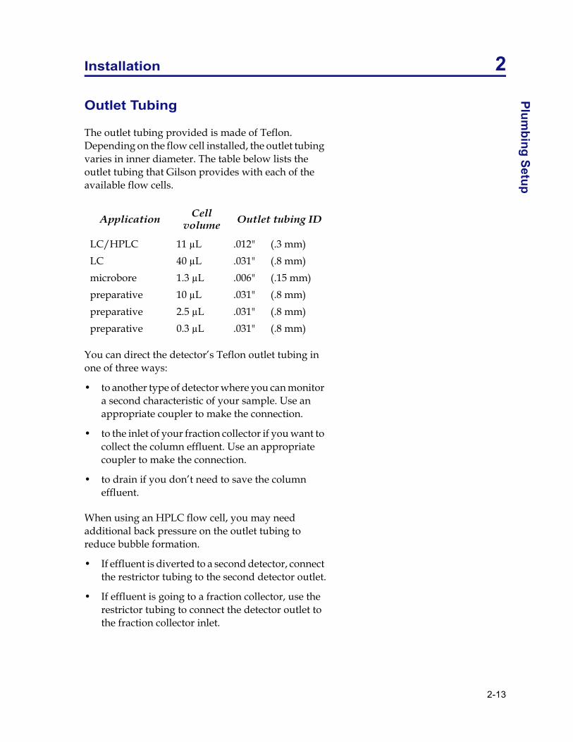
The outlet tubing provided is made of Teflon. Depending on the flow cell installed, the outlet tubing varies in inner diameter. The table below lists the outlet tubing that Gilson provides with each of the available flow cells.
You can direct the detector�s Teflon outlet tubing in one of three ways:
� to another type of detector where you can monitor a second characteristic of your sample. Use an appropriate coupler to make the connection.
� to the inlet of your fraction collector if you want to collect the column effluent. Use an appropriate coupler to make the connection.
� to drain if you don�t need to save the column effluent.
When using an HPLC flow cell, you may need additional back pressure on the outlet tubing to reduce bubble formation.
� If effluent is diverted to a second detector, connect the restrictor tubing to the second detector outlet.
� If effluent is going to a fraction collector, use the restrictor tubing to connect the detector outlet to the fraction collector inlet.
Application Cell volume Outlet tubing ID
LC/HPLC 11 µL .012" (.3 mm)LC 40 µL .031" (.8 mm)microbore 1.3 µL .006" (.15 mm)preparative 10 µL .031" (.8 mm)preparative 2.5 µL .031" (.8 mm)preparative 0.3 µL .031" (.8 mm)

Installation 2
2-14
Plum
bing
Set
up In place of the 10-foot restrictor tubing you can use a mechanical regulator (part number 36070905), available from Gilson.
Note: You will not need the restrictor tubing or a regulator valve when a prep flow cell is installed.
Instructions for replacing the inlet tubing and its fittings are found in Chapter 4, Maintenance.
Power Connection
Connect the power receptacle to an AC power source with the supplied power cord. You can purchase a power strip from Gilson for use with your Gilson HPLC System.

3-1
Operation 3
The 112 UV Detector is a rugged, economical, fixed-wavelength detector for analytical or preparative HPLC and LC. A front panel knob allows selection of the wavelength to monitor the absorbency of almost any sample.

Operation 3
3-2
Star
t Up Start Up
After you have made the connections described in Chapter 2, Installation, press the front panel MAINS power switch to activate the 112.
The 112 requires a 1 hour warm up time to operate at maximum sensitivity. At lower sensitivities, you can use the 112 after less than 1 hour.
After the 112 is warmed up, it is ready to begin detection. However, you must set the parameters described in Before the Run on page 3-3. Set these parameters in the order shown on the following pages.

3-3
Operation 3B
efore the Run
Before the Run
Wavelength
The lamp/filter assembly that you specified on your order was installed at the factory.
Your detector is equipped with the 254/280 nm lamp. Decide which monitor wavelength you wish to use. Use the front panel knob to select a wavelength:
� push the knob in to monitor at 254 nm
� pull the knob out to monitor at 280 nm.
Instructions for changing lamp filter assemblies are found in Chapter 4, Maintenance.
Recorder Baseline
Set the SENSITIVITY knob on the front panel to ZERO.
Using the Zero control on your recorder, set the recorder baseline position. Gilson recommends a 10% offset from the bottom of the chart.
Sensitivity
Adjust the 112 SENSITIVITY knob to the desired operating sensitivity. The setting that you choose dictates the full-scale height of a trace on a recorder.
To set the sensitivity, you must consider two factors�flow-cell path length and sample concentration.

Operation 3
3-4
Bef
ore
the
Run At a constant SENSITIVITY setting, the maximum
full-scale height (AUFS) increases with decreasing path length. As you decrease the flow cell�s path length from 10 mm, it takes increasing amounts of material to achieve comparable peak heights.
Choose one of the ten front-panel SENSITIVITY settings if your 112 contains a standard 10 mm path length flow cell. If a different flow cell is installed, consult the table on page 3-4 to find the adjusted full-scale sensitivity (AUFS) for each of the front-panel settings.
Path length Maximum full-scale sensitivity*
10 mm 1 AUFS5 mm 2 AUFS2 mm 5 AUFS0.5 mm 20 AUFS0.1 mm 100 AUFS* with front panel SENSITIVITY set to 1
Full-Scale Sensitivity of Optional Flow Cells
Flow Cell Path Length
5 mm 2 mm 0.5 mm 0.1 mm
Fron
t P
anel
Set
ting
1 2 AUFS 5 AUFS 20 AUFS 100 AUFS
0.5 1 2.5 10 50
0.2 0.4 1 4 20
0.1 0.2 0.5 2 10
0.05 0.1 0.25 1 5
0.02 0.04 0.1 0.4 2
0.01 0.02 0.05 0.2 1
0.005 0.01 0.025 0.1 0.5
0.002 0.004 0.01 0.04 0.2
0.001 0.002 0.005 0.02 0.1

3-5
Operation 3B
efore the Run
You can ensure that your peaks appear on-scale by running test chromatograms at various SENSITIVITY settings.
When you set the SENSITIVITY knob to a small number, the 112 will monitor at high sensitivity. As you turn the knob clockwise, the sensitivity increases.
Consider the examples and diagrams on the following pages as illustrative guides for setting SENSITIVITY.
Operation 3
3-6
Bef
ore
the
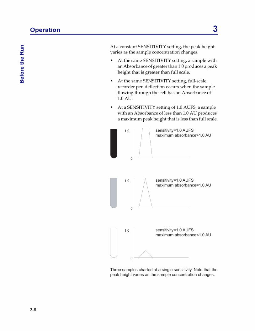
Run At a constant SENSITIVITY setting, the peak height
varies as the sample concentration changes.
� At the same SENSITIVITY setting, a sample with an Absorbance of greater than 1.0 produces a peak height that is greater than full scale.
� At the same SENSITIVITY setting, full-scale recorder pen deflection occurs when the sample flowing through the cell has an Absorbance of 1.0 AU.
� At a SENSITIVITY setting of 1.0 AUFS, a sample with an Absorbance of less than 1.0 AU produces a maximum peak height that is less than full scale.

3-7
Operation 3B
efore the Run
At a constant sample concentration, the peak height varies as the SENSITIVITY setting changes.
� At a SENSITIVITY setting of 1.0 AUFS, a sample with an Absorbance of 0.1 AU produces a maximum peak height that is less than full scale.
� At a SENSITIVITY setting of 0.1 AUFS, that same sample causes full-scale pen deflection.
� At a SENSITIVITY setting of 0.01 AUFS, that same sample produces a maximum peak height that is greater than full scale.

Operation 3
3-8
Bef
ore
the
Run Detector Baseline
Fill the detector�s flow cell by pumping pure mobile phase through the inlet tubing.
When mobile phase is flowing and all air bubbles have been removed from the inlet tubing and flow cell, press the AUTOZERO button on the front panel. The digital meter will display �00.0� (±0.1). The recorder should still be set to the baseline.
Note: You should be sure that mobile phase is flowing well before you press AUTOZERO because air bubbles, drift and noise will interfere with the autozero process.
Time Constant
The TIME CONSTANT is a measure of the amount of electronic filtering used to reduce baseline noise effects.
If you accurately set the TIME CONSTANT, you�ll obtain traces with low baseline noise and good peak shape. A value of 0.5 or 1.0 (seconds) works well under most conditions.
� As you increase the TIME CONSTANT value, increased filtering results in a smoother baseline. When the time constant is too large, reduction of baseline noise may be offset by decreased peak heights.
� As you decrease the TIME CONSTANT value, sharper peaks are detected with good resolution.

3-9
Operation 3B
efore the Run
To approximate the time constant value:
� set the TIME CONSTANT to 0.5 or 1.0
� perform a typical separation using your sample
� measure the width of an average peak at half-height
� the desired time constant will be roughly 1/20�1/10 of the measured peak width value.

Operation 3
3-10
Dur
ing
the
Run During the Run
After setting the baseline, the SENSITIVITY, and the TIME CONSTANT, you are ready to begin the run. Start the flow through the column and inject the sample.
Digital Display
The digital display at the left side of the front panel shows the percent of full-scale recorder pen deflection.
To calculate the Absorbance of your samples, you must know the full-scale sensitivity (see Sensitivity) and the path length of the flow cell. You must also monitor the digital display.
Use the following formula to calculate Absorbance:
Consider the examples and diagrams on the following pages as illustrative guides for interpreting the digital display.
A change in the sample concentration affects the digital readout and the peak height if the SENSITIVITY setting and path length are held constant:
SENSITIVITY = 1 AUFSpath length = 10 mm
� Effluent that causes the display to show �150.0� (percent full scale) has an absorbance of 1.5 AU. The maximum peak height recorded is greater than full-scale height.
Abs sensitivity AUFS( ) DigitalReadout100
-----------------------------------------× 10Pathlength mm( )-------------------------------------------×=

3-11
Operation 3D
uring the Run
� Effluent that causes the display to show �15.0� (percent full scale) has an absorbance of 0.15 AU. The maximum peak height recorded is 15% of full-scale height.
� Effluent that causes the display to show �1.5� (percent full scale) has an Absorbance of 0.015 AU. The maximum peak height recorded is 1.5% of full-scale height.
The readout can display up to 2X full-scale (199.9%).

Operation 3
3-12
Dur
ing
the
Run A change in the SENSITIVITY setting affects the
digital readout and the peak height if the path length and sample concentration are held constant:
Maximum Absorbance = .015 AUpath length = 10 mm
� At a SENSITIVITY setting of 1.0 AUFS, the display shows �1.5� (percent full scale) and the maximum peak height recorded is 1.5% of full-scale height.
� At a SENSITIVITY setting of 0.1 AUFS, the display shows �15� (percent full scale) and the maximum peak height recorded is 15% of full-scale height.
� At a SENSITIVITY setting of 0.01 AUFS, the display shows �150� (percent full scale) and the maximum peak height recorded is greater than full-scale height.

3-13
Operation 3D
uring the Run
A change in the path length affects the digital readout and the peak height if the SENSITIVITY setting and sample concentration are held constant:
Maximum Absorbance = 1.5 AUSENSITIVITY = 1 AUFS
� In a flow cell with 10 mm path length, the display shows �150� (percent full scale) and the maximum peak height recorded is greater than full-scale height.
� In a flow cell with 2 mm path length, the display shows �30� (percent full scale) and the maximum peak height recorded is 30% of full-scale height.
� In a flow cell with 1 mm path length, the display shows �1.5� (percent full scale) and the maximum peak height recorded is 15% of full-scale height.

Operation 3
3-14
Dur
ing
the
Run Event Mark
When you press the EVENT button or send a remote event signal, a negative spike appears on the recorder trace on the two variable output channels. Event marks do not appear on the fixed output channel.
The remote event signal can be activated by a fraction collector, a hand-held switch or a properly equipped injector. To install a remote event switch, see Chapter 2, Installation.
Autozero
When you press the AUTOZERO button or send a remote autozero signal, the detector baseline is reset to zero.
The remote autozero signal can be activated by a system controller, a hand-held switch or a properly equipped injector. To install a remote event switch, see Chapter 2, Installation.

3-15
Operation 3M
obile Phase Tips
Mobile Phase Tips
Degas Solvents and Buffers
Always use degassed, HPLC-grade solvents (including water) and buffers for your mobile phase.
If the back pressure on the flow cell is sufficiently low, gas bubbles may still appear, even when using degassed solvents. This can be avoided easily by connecting the pressure-regulator tubing supplied with the detector to the outlet tubing. You can also purchase a back pressure regulator valve from Gilson.
Check UV Absorbance of Solvents
Impure solvents can absorb significant quantities of UV light even when the UV cutoff may be below the monitoring wavelength. This can result in an inability to accurately set the baseline to zero. Remember to use only HPLC-grade solvents.
Manufacturer�s specifications list the cutoff value (the wavelength at which the solvent is opaque) below which a solvent or buffer should not be used as a mobile phase constituent.
Interference can still occur above the rated limit, particularly when the solvent composition changes during a run. This frequently appears as a gradual baseline shift.
The table below lists commonly used solvents with low UV cutoffs.
Solvent UV cutoff
Acetonitrile 190 nmCyclohexane 200Cyclopentane 200Decahydronaphthalene 200Ethanol 210

Operation 3
3-16
Mob
ile P
hase
Tip
s
Heptane 200Hexadecane 190Hexane 195Hexanes 210Isooctane 197Methanol 205Methylene chloride 233Pentane 205i-Pentanol 208i-Propanol 205n-Propanol 240Tetrahydrofuran 212Water <190
Solvent UV cutoff

4-1
Maintenance 4
Follow these instructions if:
� the flow cell needs to be cleaned or replaced
� the lamp, filter or tubing needs to be replaced
� you wish to change the unit�s monitor wavelength
You should not attempt any maintenance that is not described in this chapter. If you suspect other problems with the detector, contact Gilson or your regional Gilson representative.
If you will use several flow cells with this detector, you should purchase additional flow cell assemblies from Gilson. Then follow the flow cell removal/replacement instructions on page 4-4.
To change the monitor wavelength of your unit, you must purchase a complete lamp and filter assembly from Gilson. Then follow the lamp/filter replacement instructions on page 4-14.

Maintenance 4
4-2
Flow
Cel
l Mai
nten
ance Flow Cell Maintenance
Follow these instructions if you need to clean or replace the flow cell. You can purchase replacement flow cells from Gilson.
Be extremely careful when working with the flow cell and its fittings. Flow cells are made of quartz and are considered expendable. They are not covered by Gilson�s warranty if damaged or broken during any maintenance procedure.
Flow Cell Cleaning (Interior)
There are two ways to clean a flow cell that has become coated with UV absorbing material:
� solvent cleaning
� acid cleaning
Solvent cleaning
If you suspect that droplets of an organic-soluble contaminant or immiscible solvent contaminate the flow cell, draw or pump a series of miscible solvents through the cell.

4-3
Maintenance 4Flow
Cell M
aintenance
Either of these solvent series will remove contaminants with a wide range of solubilities:
� methanol, then tetrahydrofuran, then methylene chloride, and then methanol again
� hexane, then isopropanol, then methanol, then water
Acid cleaning
If you suspect that residual proteins contaminate the flow cell, draw 50% nitric acid through the cell. Acid cleaning is a more thorough technique, though much more care must be taken.
CAUTION! Take all necessary precautions to avoid contact with eyes, skin, clothing, and equipment surfaces.
Using a 1/4-28 coupler, connect a Luer-lock end fitting to the 1/4-28 fitting on the outlet tubing.
Attach a large glass syringe to the Luer-lock end.
Place the end of the inlet tubing into a reservoir of 50% nitric acid.
Draw nitric acid through the cell.
Note: Do not pump acid through the cell! You should never put acid under pressure. Use nitric acid. Do not use halogenated acid.
After the acid flush, draw HPLC-grade water through the cell in the same manner.
Reconnect the column to the inlet tubing. Redirect the outlet tubing to drain.
Finish by pumping HPLC-grade water to cleanse the last traces of acid.
To be sure that all acid has been removed, monitor the pH of the final outflow.

Maintenance 4
4-4
Flow
Cel
l Mai
nten
ance Flow Cell Removal/Replacement
Proper maintenance of the detector includes periodic removal of the flow cell for cleaning. You should remove and clean the cell immediately if a leak occurs at the cell inlet or outlet.
Note: If you have experienced flow cell leakage, you should replace the ferrule on the end of the inlet tubing. See Inlet Tubing Replacement on page 4-9 for instructions.
Remove faceplate
Unscrew the thumbscrews on the front panel faceplate.
Remove the entire flow cell assembly by sliding it towards you. You will feel some resistance as you remove it.
From the right side of the assembly, you will see:
� the flow cell, inserted into a rectangular hole
� the reference aperture, in a circular hole
4-5
Maintenance 4Flow
Cell M
aintenance
Loosen fittings
Loosen the 1/4-28 inlet and outlet fittings located above and below the flow cell.
Remove/clean cell
Carefully invert the assembly until the cell drops into the palm of your hand. The reference aperture plate is secure and will not drop out.
Moisten the quartz windows with alcohol or a laboratory cleaning solution. Then wipe the windows with a piece of lens paper or lint-free towel.
Clean the inside of the flow cell mounting area with a lint-free towel soaked in alcohol.
Carefully dry all surfaces of the assembly.
Replace cell
Without touching the quartz windows, carefully insert the flow cell into its receptacle.
Note: One corner of the cell is beveled. Be sure to align that edge with the bevel on the receptacle.
Seat the flow cell firmly. Push the cell as far into the hole as it will go. A poorly aligned flow cell may restrict or block flow.

Maintenance 4
4-6
Flow
Cel
l Mai
nten
ance Secure tubing
Stainless steel inlet tubing
Position a 1/4-28 fitting and a ferrule on the flow-cell end of the stainless steel tubing as shown in the illustration below. The tubing should extend about 1 mm beyond the ferrule.
Finger-tighten the inlet fitting. As you tighten the fitting, the tubing will be pushed flush with the end of the ferrule.
Teflon inlet tubing
Position a 1/4-28 fitting and an Omnifit gripper on the flow-cell end of the Teflon inlet tubing as shown in the illustration on the next page. The gripper should be flush with the end of the tubing.
Finger tighten the inlet fitting. Then firmly tighten the inlet fitting using a 5/16" wrench (1/8 turn).

4-7
Maintenance 4Flow
Cell M
aintenance
Teflon outlet tubing
Position a 1/4-28 fitting and an Omnifit gripper on the flow-cell end of the Teflon outlet tubing as shown in the previous illustration.
Finger tighten the outlet fitting. Then firmly tighten the outlet fitting using a 5/16" wrench (1/8 turn).
Inspect flow cell
Inspect the quartz window again. If it is dirty, wipe once more with lens paper.
Check flow
Before you replace the flow cell assembly into the detector, test the integrity of the inlet and outlet fittings. Reconnect the inlet tubing to your system and initiate flow.
If you notice leakage from the inlet or outlet fittings, you must remove, clean, and re-install the flow cell. Carefully install the fittings as described previously.

Maintenance 4
4-8
Flow
Cel
l Mai
nten
ance Replace faceplate
When no leaks are found, replace the flow cell assembly into the detector. Tighten the thumbscrews on the flow cell assembly faceplate. Reconnect the inlet and outlet tubings to your system.
Flow Cell Unclogging
To try to eliminate a blockage from the cell or inlet or outlet tubing:
Remove faceplate
Unscrew the thumbscrews on the front panel faceplate.
Remove the entire flow cell assembly by sliding it towards you. You will feel some resistance as you remove it.
Pump solvent
Very carefully pump solvent backwards through the flow cell. Connect a high-pressure pump to the outlet and direct the inlet to waste.
CAUTION: Set the maximum pressure below 300 PSI (20 BAR)!
Beginning at a flow rate of 0.1 mL/min, gradually increase the flow rate, in increments of 0.1 mL/min.
A significant pressure drop indicates that the blockage has been removed.

4-9
Maintenance 4Flow
Cell M
aintenance
Purchasing Other Flow Cells
The standard quartz flow cell contains an 11 µL cavity with a 10 mm path length.
Additional flow cell/reference aperture assemblies are available from Gilson. With a choice of several flow cells, you can quickly and easily vary the detection limits and increase the versatility of the detector.
Assemblies contain a flow cell, a reference aperture plate and tubing of the appropriate inner diameter (ID).
Other flow cell assemblies available from Gilson are listed in Chapter 1, Introduction.
Inlet Tubing Replacement
Note: You should ensure that the inner diameter of your inlet tubing is appropriate for the flow cell that is installed.
You can purchase pre-bent stainless steel inlet tubing for use with the standard HPLC flow cell [ID 0.010" (0.25 mm)] or with the microbore flow cell [ID 0.007" (0.18 mm)].
Other flow cells require Teflon inlet tubing as specified in Chapter 2, Installation.
Remove old tubing
To remove old stainless steel or Teflon inlet tubing, remove the fitting from the column end.
Unscrew the thumbscrews on the front panel faceplate.
Remove the entire flow cell assembly by sliding it towards you. You will feel some resistance as you remove it.
Pull the old tubing through inlet hole on the faceplate.

Maintenance 4
4-10
Flow
Cel
l Mai
nten
ance Secure new tubing
Push the new tubing through the inlet hole on the rear of the faceplate.
Stainless steel inlet tubing
Locate a new Upchurch ferrule from the detector accessory package. It is identical to the ferrule you just removed.
Place the fitting and ferrule on the flow-cell end of the stainless steel tubing as shown in the illustration above. The tubing should extend about 1 mm beyond the ferrule.
Finger tighten the inlet fitting. As you tighten the fitting, the inlet tubing will be pushed flush with the end of the ferrule.

4-11
Maintenance 4Flow
Cell M
aintenance
Teflon inlet tubing
Position a 1/4-28 fitting and an Omnifit gripper on the end of the inlet tubing as shown below. Use a razor blade to cut the tubing and a needle-nosed pliers to pull the tubing through the gripper.
Teflon outlet tubing
Finger tighten the outlet fitting. Then firmly tighten the outlet fitting using a 5/16" wrench (1/8 turn).

Maintenance 4
4-12
Flow
Cel
l Mai
nten
ance Check flow
Before you replace the flow cell assembly into the detector, test the integrity of the inlet and outlet fittings. Reconnect the inlet tubing to your system and initiate flow.
If you notice leakage from the inlet or outlet fittings, you must remove, clean, and re-install the flow cell. Carefully install the inlet fitting as described above.
Replace faceplate
When no leaks are found, replace the flow cell assembly into the detector. Tighten the thumbscrews on the flow cell assembly faceplate. Reconnect the inlet and outlet tubings to your system.
Outlet Tubing Replacement
Remove old tubing
Unscrew the thumbscrews on the front panel faceplate.
Remove the entire flow cell assembly by sliding it towards you. You will feel some resistance as you remove it.
Pull the old tubing through the outlet hole on the faceplate.
Secure new tubing
Push the new tubing through the outlet hole on the rear of the faceplate.

4-13
Maintenance 4Flow
Cell M
aintenance
Position a 1/4-28 fitting and an Omnifit gripper on the end of the outlet tubing as shown below. Use a razor blade to cut the tubing and a needle-nosed pliers to pull the tubing through the gripper.
Finger tighten the outlet fitting. Then firmly tighten the outlet fitting using a 5/16" wrench (1/8 turn).
Check flow
Before you replace the flow cell assembly into the detector, test the integrity of the inlet and outlet fittings. Reconnect the inlet tubing to your system and initiate flow.
If you notice leakage from the inlet or outlet fittings, you must remove, clean, and re-install the flow cell. Carefully install the inlet fitting as shown on page 4-9.
Replace faceplate
When no leaks are found, replace the flow cell assembly into the detector. Tighten the thumbscrews on the flow cell assembly faceplate. Reconnect the inlet and outlet tubings to your system.

Maintenance 4
4-14
Flow
Cel
l Mai
nten
ance Lamp Replacement
Caution! Never touch a hot lamp! After turning off the detector, wait 30 minutes or more before replacing the lamp.
Before performing the maintenance described below, you must unplug the detector from its power source. Do not remove the cover until you have done this.
Remove cover
Remove the cover by removing the four screws from the sides of the unit. Lift the cover straight up.
Place the detector in front of you, so you are facing the front panel.
Locate the lamp/filter assembly below and to the right of the white plastic knob (the filter-block release). Use the following drawing as a reference.
On the right side panel of the detector is a cut-out that eases access to the lamp assembly.

4-15
Maintenance 4Flow
Cell M
aintenance
Disconnect connector
The cable from the lamp/filter assembly terminates with a 6-pin connector that is visible at the right side of the unit. Disconnect the 6-pin connector.
Remove lamp/filter assembly
To remove the lamp/filter assembly,
� unscrew and remove the 254/280 wavelength selection knob (standard units only)
� lift the white plastic knob and slide the lamp/filter assembly toward the rear of the unit
Detach old lamp (note old lamp type)
To detach a mercury (or phosphor-coated mercury or 254/280 nm) lamp from the lamp/filter assembly, carefully remove the two screws that secure the lamp to the filter block. Do not touch the surface of the lamp.
Note: If you need to install a new filter, you should do that now, while the unit is dissembled. Instructions for filter replacement are found on page 4-17.
Install new lamp (note lamp type)
To install a new 254/280 nm lamp:
1 Position the lamp so it is adjacent to the filter. Be sure that the lamp is not inverted relative to the filter block. (The new lamp is pre-aligned in a mounting block.)
2 Secure the lamp to the filter block with two screws
3 Replace the lamp/filter assembly (lift the white knob).
4 Reconnect the 6-pin connector.

Maintenance 4
4-16
Flow
Cel
l Mai
nten
ance 5 Route the lamp cord beneath the fan at the rear of
the detector.
6 Place the 254/280 nm wavelength selection knob shaft through the front panel hole into the lamp and secure it to the lamp/filter assembly (standard units only).
Replace cover
Replace and secure the detector�s cover using the four screws you removed earlier.

4-17
Maintenance 4Flow
Cell M
aintenance
Filter Replacement
Before performing the maintenance described below, you must unplug the detector from its power source. Do not remove the cover until you have done this.
Note: To replace a filter, you will need internal C-ring pliers.
Unplug the 6-pin lamp connector and remove the lamp/filter assembly as described in Lamp Replacement on page 4-14.
Using C-ring pliers, remove the C-ring from the circular chamber on the filter block.
Invert the filter block and let the filter cartridge drop into the palm of your hand.
Taking care not to touch the optical surface, place the new filter into its chamber. Secure the new filter cartridge with the C�ring.

5-1
Troubleshooting 5
If you encounter a problem while operating the 112 UV Detector, refer to the following pages. If you cannot solve or isolate the problem, contact the Gilson Customer Service Department or your local Gilson representative. See Before calling us on page 5-6.

Troubleshooting 5
5-2
Trou
bles
hoot
ing
Cha
rt Troubleshooting Chart
Baseline Spikes
Eliminate bubbles that pass through the flow cell by degassing solvents.
Check fittings for a leak in system, repair as needed.
Voltage transients on a single circuit may interfere with detector output.
� ensure that the detector and recorder are connected to the same outlet
� eliminate voltage transients by connecting detector and recorder power lines to a constant voltage transformer or line filter
Reduce pump noise by changing compensation setting on pump and by examining check valves.
Baseline Noise
Allow lamp to warm up.
Check flow cell for contamination.
If you see baseline deflection when back pressure is exerted on the flow cell, you probably have bubbles trapped in the cell. Try one of these methods to eliminate bubbles:
� increase back pressure on the cell by connecting pressure regulator tubing to the flow cell outlet
� flush flow cell using a syringe filled with fresh solvent
� raise the collector vial to a level higher than the cell
Check grounds on all instruments; eliminate ground loops by plugging detector and recorder into the same outlet.

5-3
Troubleshooting 5Troubleshooting C
hart
Eliminate drafty air currents.
Eliminate smoke from the environment.
Lamp may be weak.
Filter may be defective.
Baseline Drift
Eliminate changes in ambient temperature. If drift is dependent on temperature, eliminate drafts and avoid areas of direct sunlight.
Check flow cell for contamination.
Check for contaminated or �bleeding� column. If drift disappears after you stop the flow, then check the solvents and regenerate or replace column.
If you see baseline deflection when back pressure is exerted on the flow cell, you probably have bubbles trapped in the cell. Try one of these methods to eliminate bubbles:
� increase back pressure on the cell by connecting pressure regulator tubing to the flow cell outlet
� flush flow cell using a syringe filled with fresh solvent
� raise the collector vial to a level higher than the cell
Check pump or delivery system to determine that flow rate is constant.
Lamp may be weak.
Filter may be defective.
Check flow cell for leak.

Troubleshooting 5
5-4
Trou
bles
hoot
ing
Cha
rt Unable to Zero
Check connections to recorder. Refer to recorder�s troubleshooting instructions.
Check purity and UV-cutoff of solvents. Use only HPLC-grade solvents.
Eliminate bubbles trapped in flow cell. Increase flow rate and apply back pressure by using syringe or septum to momentarily block exit stream.
Check flow cell for contamination.
Check for contaminated column. If necessary, regenerate or replace column.
Check flow cell for leak. Tighten flow cell connections.
No UV Illumination
Fuse may be blown.
4-pin power supply connector and/or 6-pin lamp connector may be loose.
Lamp may be defective.
Decreased Response to Known Sample Concentration
Lamp may be weak.
Filter may be defective.
Check connections to recorder.
Verify sample concentration and solvent.

5-5
Troubleshooting 5Troubleshooting C
hart
Unit not functioning
Check cord and power connection.
Fuse may be blown.

Troubleshooting 5
5-6
Rep
air a
nd R
etur
n Po
licie
s Repair and Return Policies
Before calling us
Gilson Customer Service personnel will be able to serve you more efficiently if you have the following information:
� the serial number and model number of the instruments involved. The serial number is visible on the back panel of the detector.
� the installation procedure you used
� list of concise symptoms
� list of operating procedures and conditions you were using when the problem arose
� list of other devices connected to the fraction collector and a description of those connections
� list of other electrical connections in the room
Warranty repair
Units covered under warranty will be repaired and returned to you at no charge. If you have any questions about applicability, please contact Gilson or your authorized representative.
Non-warranty repair
For out-of-warranty repairs, contact your local Gilson representative or the Gilson Customer Service Department. A Customer Service representative will discuss service options with you and can assist in making arrangements to return the equipment, if necessary.
Rebuilt exchange
For some units, rebuilt exchange components are available. Contact Gilson for details.

5-7
Troubleshooting 5R
epair and Return Policies
Return procedure
In the United States, contact the Gilson Customer Service Department to obtain authorization before returning any Gilson equipment. To return a piece of equipment:
� Carefully pack the unit to prevent damage in transit. Check with Gilson regarding proper method of shipment. No responsibility is assumed by Gilson for damage caused by improperly packaged instruments. Indicate the authorization on the carton and on the packing slip.
� Always insure for the replacement value of the unit.
� Include a description of symptoms, your name, address, phone number, and purchase order to cover repair costs, return and shipping charges, if your institution requires it. Ship to:
Gilson, Inc.Attention: Customer Service(indicate the authorization here)3000 W. Beltline HighwayMiddleton, WI 53562
Outside the United States, contact your Gilson representative for return procedures.


A-1
List of Expendable Parts A
Part Number Description
030554 Lamp/Filter Assembly, 254/280 nm, mercury.
030726 Restrictor tubing for HPLC flow cell, 0.3 mm ID x 10 ft., Teflon
090731 Outlet tubing assembly for HPLC/LC flow cell, 0.3 mm ID, Teflon
090732 Outlet tubing assembly for microbore flow cell, 0.18 mm ID, Teflon
090738 Inlet/Outlet tubing assembly for prep flow cell, 0.8 mm ID, Teflon
100719 Restrictor tubing for LC flow cell, 0.5 mm ID x 10 ft., Teflon
100731 Autozero/Event Cable.
495018 Luer fitting, female
495019 Luer fitting, male
03032710 254/280 nm replacement Mercury lamp
03041501 Analytical flow cell, 11 µL, 10 mm path length
03043001 LC flow cell, 40 µL, 10 mm path length
03044001 2 mm path length flow cell for preparative applications, 10 µl volume.
03044501 0.5 mm path length flow cell for preparative applications, 2.5 µl volume.
03045106 Inlet tubing for HPLC/LC flow cell, stainless steel, 0.25 mm ID

List of Expendable Parts A
A-2
03045107 Inlet tubing for microbore flow cell, stainless steel, 0.15 mm ID
03046001 5 mm path length flow cell for microbore applications, 1.3 µl volume.
03046501 0.1 mm path length flow cell for preparative applications, 0.3 µl volume.
49041001 Upchurch Finger-tight column 10-32 fitting
49041011 Upchurch ferrule, 1/16"
49041012 Upchurch male nut for ferrule, 1/16"
49041034 PEEK ferrule for 1.6 mm OD tubing, anti-twist (Upchurch P-250)
490410115 LT-115, PEEK SHORT NUT 1/16"
6374022611 Pomona Cable Adapter, banana plugs to binding posts.
6750054007 Fuse, 0.5 amp, 3 AG Slo-Blo for 220/240V units
6750104007 Fuse, 1 amp, 3 AG Slo-Blo for 100/115V units
7080200202 Pomona Recorder Cable.
7080200203 RECORDER CABLE TINNED LEADS
7080316105 Power cord, 115V
7080316106 Power cord, 220/240V, European plug
03045106T Titanium inlet tubing (no fittings).
F1410050 1/4-28 couplers for outlet tube fittings
Part Number Description

B-1
Flow Cell Pressures in PSI B
The following table lists expected pressures when using the 112 UV Detector with different flow cells at different flow rates. To obtain these pressures, water was pumped through the detector�s flow cell.
Path Length (µL Volume)
mL/min
0.1 mm
(0.3 µL)
0.5 mm
(2.5 µL)
2 mm
(10 µL)
5 mm
(1.3 µL)
10 mm
(11 µL)
10 mm
(40 µL)
20 0 0 0 0 0 040 3 0 0 0 0 060 17 0 0 4 0 080 22 0 0 12 5 0100 36 0 0 20 7.5 0120 43.5 0 0 24.5 8 2140 55 0 1 27 8.5 2160 69 1 1 32 8.5 2180 88 1 1.5 41.5 10 2200 117 3 3 53 14.5 4

Flow Cell Pressures in PSI B
B-2
If you were to chart the information, it would look like this.
The above resulted from connecting the detector to a pump, manometric module, and pressure gauge, shown below.


![Quality Report · 2018. 8. 15. · 0.006 -0.003 0.003 -0.001 0.002 Uncertainties (Sigma) 1.990 [pixel] 0.005 [mm] 0.664 [pixel] 0.002 [mm] 0.787 [pixel] 0.002 [mm] 0.000 0.000 0.000](https://static.fdocuments.net/doc/165x107/60fd4e48c8d80d2d9761f76c/quality-report-2018-8-15-0006-0003-0003-0001-0002-uncertainties-sigma.jpg)
![VSR · 2007. 2. 13. · i = 3 h m2 i (42) m˙ 1 = .5 [kg/s]; m˙ 2 = .5 [kg/s] (43) t 1,i = 30 [C]; t 2,i = 20 [C] (44) D e,i = 32 [mm]· 0.001 m mm ; delta t,i = 3 [mm]· 0.001 m](https://static.fdocuments.net/doc/165x107/60c6ffd80d0e74428d108471/2007-2-13-i-3-h-m2-i-42-m-1-5-kgs-m-2-5-kgs-43-t-1i.jpg)


![Debyser SI revised JK[1]...5 concentration of 1.6 µM) and 4 µl of annealed oligonucleotides (7 nM) were added in a final reaction volume of 40 µl containing 10 mM MgCl2, 5 mM dithiothreitol,](https://static.fdocuments.net/doc/165x107/5ecbada7fbb45076d521e81b/debyser-si-revised-jk1-5-concentration-of-16-m-and-4-l-of-annealed-oligonucleotides.jpg)