LT IRM - edaphic.com.au · 3 Introduction. The LT-IRM. infrared temperature sensor offers...
9
SENSORS AND SYSTEMS FOR MONITORING GROWING PLANTS LT-IRM Infrared Leaf Temperature Sensor Exclusively Distributed & Supported By:
Transcript of LT IRM - edaphic.com.au · 3 Introduction. The LT-IRM. infrared temperature sensor offers...

SENSORS AND SYSTEMS
FOR MONITORING GROWING PLANTS
LT-IRM
Infrared Leaf Temperature Sensor
Exclusively Distributed & Supported By:

3
Introduction
The LT-IRM infrared temperature sensor offers
intelligence in a rugged, easy-to-use package. Every
sensor is individually tested and calibrated within the
measurement range.
The LT-IRM probe comes in a weatherproof box with a
holder.
Installing the sensor
Install LT-IRM as close as practical to view target foliage
to be measured. Use the sensor’s holder to mount the LT-
IRM.
Please note that the LT-IRM has 5:1 field of view. The
field of view is the ratio of the distance to the object
being measured, and the diameter of the temperature
measurement area. For example, if the thermometer has
a field of view specification of 5:1, holding the
thermometer 5 meters from the target will result in a
meter diameter spot size (measurement area) on the
target. Holding the thermometer 10 meters from the
target will result in a measurement area of 2 meters, and
so on.
4
Keep the sunlight at back of the sensor.
Remember that when you shine at an angle, the beam
being cast will be oval, (similar to a flashlight beam) just
something to bear in mind.
Hold the sensor so that the beam will not see the sky or
soil, the confounding variables.
Selecting Outputs The LT-IRM sensor has the following analog and digital outputs:
Analog: 0 to 2 Vdc, or 0 to 20 mA, or 4 to 20 mA, selected by jumpers;
Digital: RS232, or RS485, or SDI-12, or UART-TTL, selected by micro-switches.
Only one analog output and one digital output may be active at a time.
The appropriate positions of jumpers and switches are described below.

5
First, please choose a right output cable for connecting the sensor to a datalogger. The cable must be round with four wires for analog outputs and five wires for digital outputs. The maximal diameter of the cable is 6.5 mm. The cable length shall not exceed 10 m for all outputs except the current outputs and RS485 with about 1 km maximal length.
Run the cable through the appropriate inlet and connect accordingly:
Power wires to XT1
Analog output to XT6
Digital output to the appropriate contact ofthe terminal XT2-XT5
Select the desired type of digital output by using the selector switch as follows:
RS232
Position 3-1
RS485
Position 2-1
SDI-12
Position 3-0
UART TTL
Position 2-0

6
Figure 1. PCB
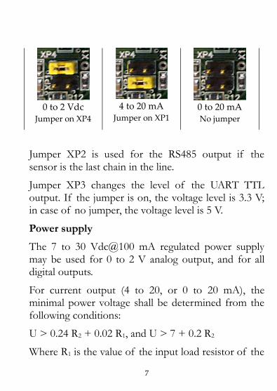
Select the desired type of analog output by appropriate position of the jumper XP1, XP4 as follows:
7
0 to 2 Vdc Jumper on XP4
4 to 20 mA Jumper on XP1
0 to 20 mA No jumper
Jumper XP2 is used for the RS485 output if the sensor is the last chain in the line.
Jumper XP3 changes the level of the UART TTL output. If the jumper is on, the voltage level is 3.3 V; in case of no jumper, the voltage level is 5 V.
Power supply
The 7 to 30 Vdc@100 mA regulated power supply may be used for 0 to 2 V analog output, and for all digital outputs.
For current output (4 to 20, or 0 to 20 mA), the minimal power voltage shall be determined from the following conditions:
U > 0.24 R2 + 0.02 R1, and U > 7 + 0.2 R2
Where R1 is the value of the input load resistor of the

8
datalogger, and R2 is the power wires resistance.
Example: R1 = 500 Ohm, and R2 = 100 Ohm.
U > 0.24 x 100 + 0.02 x 500 = 12.4 V U > 7 + 0.2 x 100 = 9 V Therefore, the minimal power voltage must be above 12.4 V.
In case of using the intermittent power supply, please respect the following recommendations:
Analog outputs require at least 2 secondsexcitation time for producing stable outputsignal.
Digital outputs transmit output signal asecond after application of power.
Data logging
Digital outputs have the following data format: UART, Baud Rate = 9600, 8N1.
Decimal data format: XX.X (°C).
When using analog outputs, all possible measures for reducing instrumental errors shall be undertaken:
Screened cables.

9
Cables with low impedance.
Twisted pair cables.
Filtration of the signal with low cutofffrequency.
Isolated power supply and data logger.
Digital filtration of the signal.
Calibration table for linear analog outputs
0..2 V 4..20 mA 0..20 mA Temperature
°C
0 V 4 mA 0 mA 0
2 V 20 mA 20 mA 60
Maintenance:
The sensor’s lens is protected by a special crystal
window. Please maintain it clear for best accuracy of the
sensor. Clean it with the use of soft cloth and a glass-
cleaning agent, if necessary.
10
Specifications:
Measurement range: 0 to 60 °C
Absolute accuracy: ± 1.0 °C
Repeatability: ± 0.1 °C
Field of view: 5:1
Emissivity setting: 0.9
Spectral response: 5.5 to 14 µm
Ambient temperature: 0 to 50 °C
Sensor’s dimensions (w/holder): 140H x 90W x 150D mm
Sensor’s weight (approximate): 400 g
Protection index of the sensor: IP 54
Power requirements: 7 to 35 Vdc @ 50 mA max.
Output auto update time: 5 s
Support & Further Information Contact:
Edaphic Scientific Pty [email protected]: 1300 430 928