
LSAMP Winter 2014 Presentation HK
34
The Effects of Various Combustion Techniques in a Subsonic Turbine-less Engine Through Computational Investigation and Experimental Validation Hakob Karaoglanian PI: Dr. Chivey Wu Department of Mechanical Engineering California State University, Los Angeles 3/14/2014
-
Upload
hakob-karaoglanian-eit -
Category
Documents
-
view
159 -
download
2
Transcript of LSAMP Winter 2014 Presentation HK
The Effects of Various Combustion Techniques in a
Subsonic Turbine-less Engine Through
Computational Investigation and Experimental
Validation
Hakob Karaoglanian
PI: Dr. Chivey Wu
Department of Mechanical Engineering
California State University, Los Angeles
3/14/2014

Outline
• Background
• Objectives
• Previous work
• Experimental
Design
• Results
• Future work

What is a Jet Engine?
• Turbofan
• Turbojet
• Turboprop
• Prop fan
• Ramjet
• ScramjetPratt & Whitney JT9D Turbofan Engine

How do they work ?
Turbofan
The Brayton Cycle

Jet A-1 Jet A
Flash point 38 °C (100 °F)
Auto-ignition
temperature245 °C (473 °F)
Freezing point −47 °C (−53 °F) −40 °C (−40 °F)
Open air burning
temperatures260–315 °C (500–599 °F)
Density at 15 °C
(59 °F)
.804 kg/L
(6.71 lb/US gal)
.820 kg/L
(6.84 lb/US gal)
Specific energy 43.15 MJ/kg 43.02 MJ/kg
Energy density 34.7 MJ/L 35.3 MJ/L
Typical Physical Properties of Jet Fuel
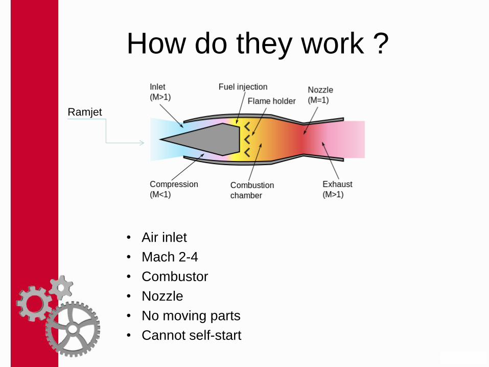
• Air inlet
• Mach 2-4
• Combustor
• Nozzle
• No moving parts
• Cannot self-start
How do they work ?
Ramjet

Problems ?
• Efficiency
• Mechanical parts
• Wear and tear
• Break down

Previous Work
• Dr. Chivey Wu
• Long ly
• Nhan Doan
• NASA-SPACE Center

Solution… Turbine-less !
P2’
Po2’
M2’
T2’
T2’
P1
Po1
M1
T1
To1
P2
Po2
M2
T2
To2
P3
Po3
M3
T3
To3
Nozzle: 1-D Isentropic Flow
Combustor: 1-D Heat Addition (Rayleigh Flow)
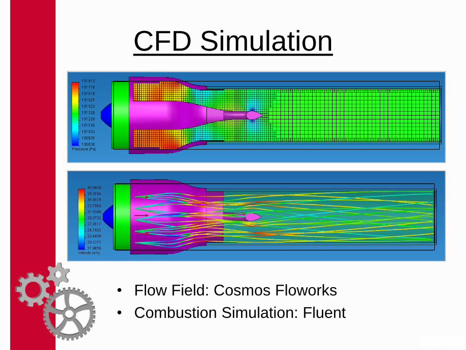
CFD Simulation
• Flow Field: Cosmos Floworks
• Combustion Simulation: Fluent

CFD Results: Swirling Flow
• Tangential Velocity Gradients

Preliminary Results
0
0.02
0.04
0.06
0.08
0.1
0.12
0.14
0 500 1000 1500 2000 2500 3000 3500
Vol
umet
ric F
low
Rat
e Q
(m
3 /s)
RPM
Volumetric Flow Rate
Wind Tunnel Data
Extrapolated Points
0
5
10
15
20
25
30
35
40
45
50
0 500 1000 1500 2000 2500 3000 3500
Ve
locity (
m/s
)
RPM
Velocity in Chamber
Wind Tunnel Data
CFD Results
0
200
400
600
800
1000
1200
1400
1600
0 500 1000 1500 2000 2500 3000 3500
Dyn
am
ic P
ressu
re (
Pa
)
RPM
Chamber Dynamic Pressure
Wind Tunnel Data
CFD Results
0
10
20
30
40
50
0 500 1000 1500 2000 2500 3000 3500
Po
we
r In
pu
t (w
)
RPM
Power Requirement
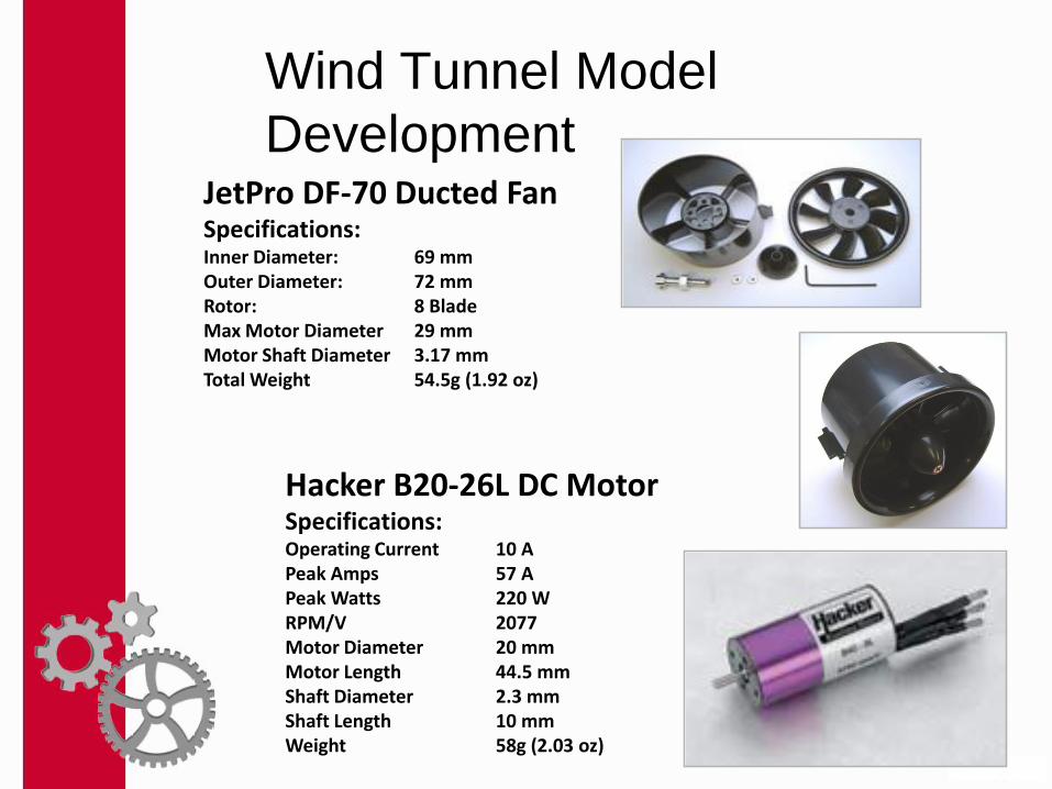
Wind Tunnel Model
Development
Hacker B20-26L DC MotorSpecifications:Operating Current 10 APeak Amps 57 APeak Watts 220 WRPM/V 2077Motor Diameter 20 mmMotor Length 44.5 mmShaft Diameter 2.3 mmShaft Length 10 mmWeight 58g (2.03 oz)
JetPro DF-70 Ducted FanSpecifications:Inner Diameter: 69 mmOuter Diameter: 72 mmRotor: 8 BladeMax Motor Diameter 29 mmMotor Shaft Diameter 3.17 mmTotal Weight 54.5g (1.92 oz)

Experimental Setup
Test
Model
Wind Tunnel LabVIEW® Software
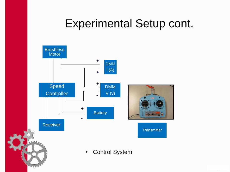
Experimental Setup cont.
Brushless Motor
Speed
Controller
Battery
Receiver
DMM
V (v)
DMM
I (A)
+
-
+
+
+
-
Transmitter
• Control System

Combustion Setup

Combustion Results
0
1
2
3
4
5
5000 7000 9000 11000 13000 15000 17000 19000
F (
N)
RPM
Experimental Thrust Performance Comparison
H2 Combustion (15 psi)
H2 Combustion (10 psi)
H2 Combustion (5 psi)
No Combustion
CFD Heat Addition
• Works !
• Efficient ?

Objectives
• Build upon the first series Turbine-less engine
• Make more efficient
• Develop mixing chamber
• Conical
• Cylindrical
• Tangential
• Incorporate different
combustible fuels
• The Fuel used in this study is
Propane

Mixing Chambers
Mass flow rate 𝑚 = ρ𝐴𝑉

Cylindrical Mixing Chamber
• Cylindrical Mixing
• Dimensions
• Number of holes
• Length
• Diameter
• Material

New EDF Specifications
Mercury Alloy 64mm 4700KV EDFSpecifications:Operating Current 13 APeak Amps 76 APeak Watts 1140 WRPM/V 1857Motor Diameter 21 mmMotor Length 45 mmShaft Diameter 2.5 mmShaft Length 10 mmWeight 162g Installed Max Thrust 1600gNumber of Blades 8

Construction of the New
Turbine-less Engine
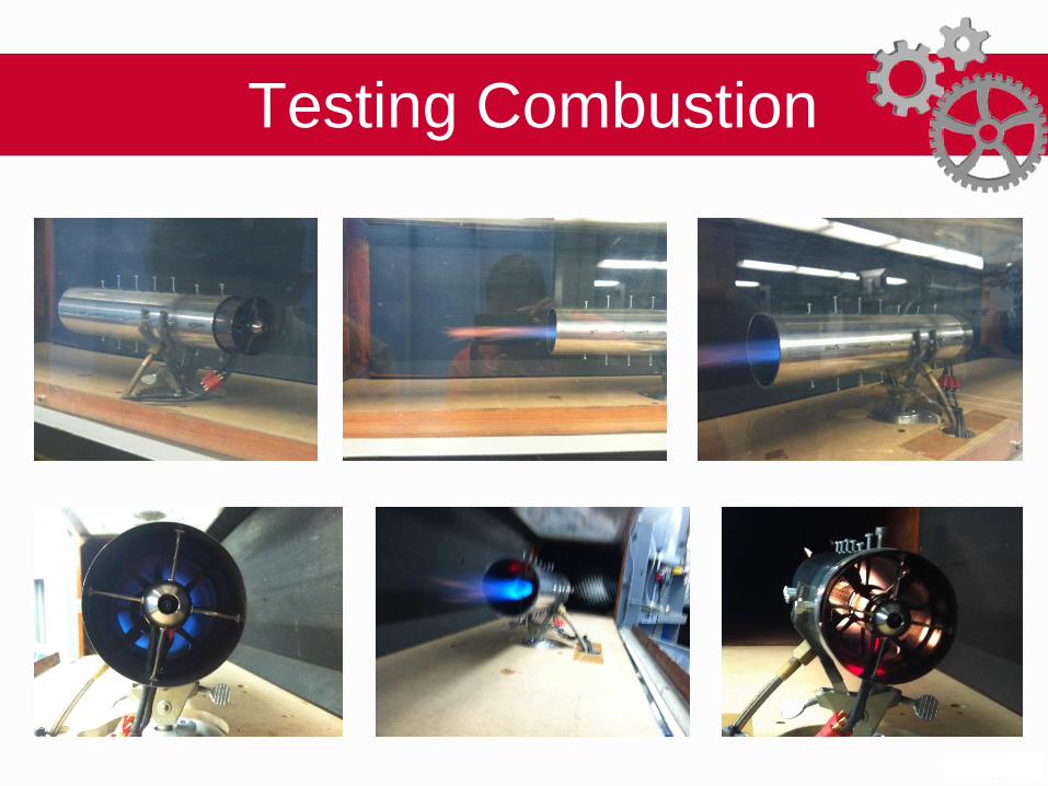
Testing Combustion

Test Results (1”x 7.5” perforated copper mixing chamber)
No
Co
mb
ust
ion
Voltage (V) Current (A)Voltage
Reading (V)RPM Power (W) Thrust (N)
18.9 1.7 0.013 11550 32.13 0.416975
16.5 4.3 0.026 16000 70.95 0.83395
17.2 3.4 0.023 14850 58.48 0.737725
18.1 2.5 0.019 13400 45.25 0.609425
15.4 5.5 0.032 17230 84.7 1.0264
13.7 7.6 0.038 18800 104.12 1.21885
12.8 8.8 0.04 19400 112.64 1.283
12.9 9.5 0.043 20000 122.55 1.379225
12.9 10.4 0.046 20600 134.16 1.47545
11.2 11.4 0.044 20500 127.68 1.4113
Co
mb
ust
ion
Voltage (V) Current (A)Voltage Reading
(V)RPM Power (W) Thrust (N)
17.6 1.6 0.013 10950 28.16 0.416975
16.8 2.4 0.018 12730 40.32 0.57735
15.3 4 0.025 15150 61.2 0.801875
12.6 7.2 0.036 18000 90.72 1.1547
11.7 8.4 0.039 18700 98.28 1.250925
11.2 9.6 0.042 19230 107.52 1.34715
11.2 10.6 0.045 20000 118.72 1.443375
11.2 11.3 0.047 20400 126.56 1.507525
11.2 11.9 0.05 20800 133.28 1.60375
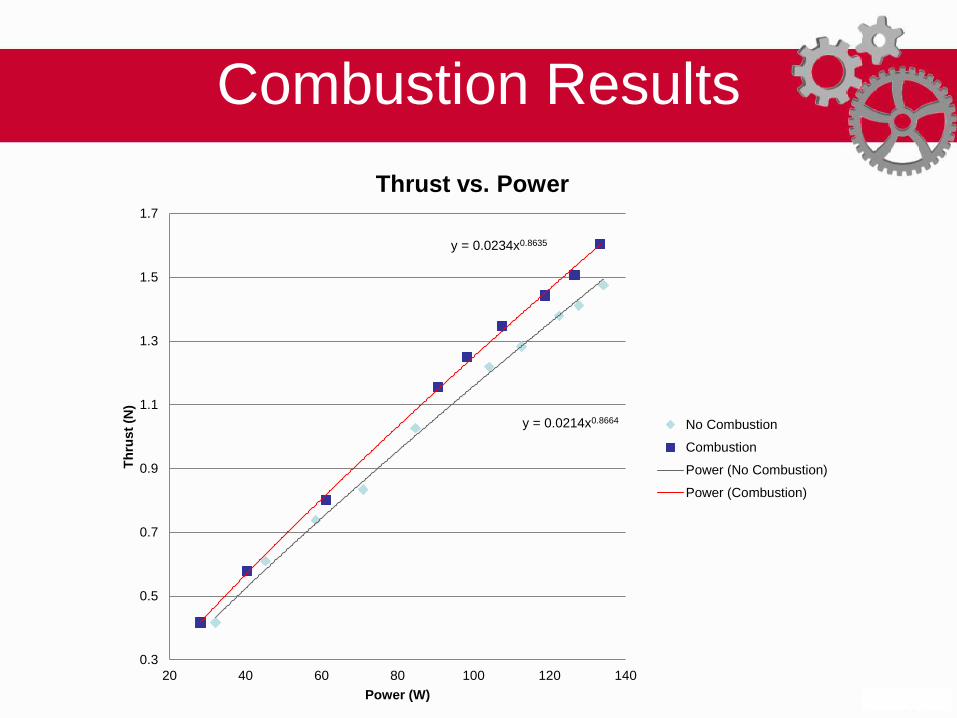
Combustion Results
y = 0.0214x0.8664
y = 0.0234x0.8635
0.3
0.5
0.7
0.9
1.1
1.3
1.5
1.7
20 40 60 80 100 120 140
Th
rust
(N)
Power (W)
Thrust vs. Power
No Combustion
Combustion
Power (No Combustion)
Power (Combustion)

Confirmation of Combustion Results
Current
(A)
Voltage
Reading
(V)
RPMPower
(W)
Thrust
(N)
9.8 0.0499 21000 147 1.60
9.1 0.0474 20400 136.5 1.52
8 0.0433 19500 120 1.39
7.6 0.0419 19100 114 1.34
6.3 0.0363 17800 94.5 1.16
5.7 0.0342 17200 85.5 1.10
4.9 0.0307 16300 73.5 0.98
4 0.0262 15100 60 0.84
3.2 0.0218 13850 48 0.70
1.3 0.0113 9400 19.5 0.36
No
Co
mb
ust
ion
Current
(A)
Voltage
Reading
(V)
RPMPower
(W)
Thrust
(N)
9.2 0.0552 20500 138 1.77
8.1 0.051 19600 121.5 1.64
8.6 0.053 20000 129 1.70
7.5 0.0478 18900 112.5 1.53
6.5 0.0438 18000 97.5 1.40
5.5 0.0396 17000 82.5 1.27
5 0.0368 16300 75 1.18
4 0.0318 15000 60 1.02
2.9 0.0259 13300 43.5 0.83
1.1 0.0143 8900 16.5 0.46
Co
mb
ust
ion

Nozzle Effects
Voltage
Reading
(V)
Voltage
(V)
Current
(A)RPM
Thrust
(N)
Power
(W)
0.014 18.6 1.7 11200 0.415058 31.62
0.0238 16.8 3.3 14400 0.705599 55.44
0.0292 15.7 4.5 15800 0.865692 70.65
0.0328 15.7 5.2 16800 0.972422 81.64
0.0354 15.7 5.8 17300 1.049504 91.06
0.04 15.7 6.6 18300 1.18588 103.62
0.0448 15.8 7.6 19400 1.328186 120.08
0.0535 15.9 9.1 20500 1.586115 144.69
No
No
zzle
- N
o C
om
bu
stio
n
Voltage
Reading
(V)
Voltage
(V)
Current
(A)RPM
Thrust
(N)
Power
(W)
0.0129 20.3 1.3 10400 0.382446 26.39
0.0255 18.1 3.2 14700 0.755999 57.92
0.033 16.6 4.8 16600 0.978351 79.68
0.0363 15.8 5.6 17500 1.076186 88.48
0.0403 15.8 6.4 18300 1.194774 101.12
0.044 15.8 7.2 19100 1.304468 113.76
0.0492 15.8 8.4 20200 1.458632 132.72
0.0556 15.8 9.5 21200 1.648373 150.1
No
zzle
- N
o C
om
bu
stio
n
Voltage
Reading
(V)
Voltage
(V)
Current
(A)RPM
Thrust
(N)
Power
(W)
0.0153 19.3 1.5 10900 0.453599 28.95
0.0224 18.3 2.4 13000 0.664093 43.92
0.0268 17.5 3.3 14600 0.79454 57.75
0.0344 15.7 5 16500 1.019857 78.5
0.0377 15.8 5.6 17200 1.117692 88.48
0.0436 15.8 7 18600 1.292609 110.6
0.048 15.8 7.8 19500 1.423056 123.24
0.056 15.8 9.2 20600 1.660232 145.36
No
No
zzle
- C
om
bu
stio
n
Voltage
Reading
(V)
Voltage
(V)
Current
(A)RPM
Thrust
(N)
Power
(W)
0.0157 24.2 1.2 10900 0.465458 29.04
0.0205 19.7 2.2 13300 0.607764 43.34
0.0296 18.2 3.6 15800 0.877551 65.52
0.0401 15.9 6 18300 1.188845 95.4
0.0447 15.8 7 19200 1.325221 110.6
0.0483 15.8 7.8 19900 1.43195 123.24
0.0571 15.8 9 21000 1.692844 142.2
0.062 15.8 10.2 22000 1.838114 161.16
No
zzle
- C
om
bu
stio
n
Adding nozzle produced no more than 2% increase in thrust… Why?

Combustion Results

Optimization: 1.5” Mixing Chamber
Voltage
(V)
Current
(A)
Voltage
Reading
(V)
RPMPower
(W)
Thrust
(N)
23.1 0.8 0.009 8,745 18.48 0.288675
21.3 2.5 0.027 14,130 53.25 0.866025
19.3 4.8 0.043 17,570 92.64 1.379225
17.4 6.9 0.054 19,570 120.06 1.73205
15.7 9.1 0.064 21,020 142.87 2.0528
15.2 9.9 0.066 21,300 150.48 2.11695
15.2 10.5 0.07 21,850 159.6 2.24525
15.2 11.3 0.075 22,400 171.76 2.405625
0 0 0 0 0 0
0 0 0 0 0 0
0 0 0 0 0 0
0 0 0 0 0 0
0 0 0 0 0 0
0 0 0 0 0 0
Engi
ne
Ass
emb
ly w
/o 1
.5 in
Co
mb
ust
or
Voltage
(V)
Current
(A)
Voltage
Reading
(V)
RPMPower
(W)
Thrust
(N)
20.2 0.7 0.005 7,700 14.14 0.160375
18.3 2.4 0.016 13,080 43.92 0.5132
16.5 4.3 0.025 15,850 70.95 0.801875
15 5.9 0.03 17,500 88.5 0.96225
13.6 7.8 0.035 18,800 106.08 1.122625
13.1 9 0.038 19,650 117.9 1.21885
13.1 10 0.042 20,500 131 1.34715
13.2 11.3 0.045 21,230 149.16 1.443375
13.2 12.3 0.049 22,000 162.36 1.571675
0 0 0 0 0 0
0 0 0 0 0 0
0 0 0 0 0 0
0 0 0 0 0 0
0 0 0 0 0 0
Engi
ne
Ass
emb
ly w
/ 1.
5 in
Co
mb
ust
or
Voltage
(V)
Current
(A)
Voltage
Reading
(V)
RPMPower
(W)
Thrust
(N)
16.1 0.6 0.003 6,000 9.66 0.096225
14.6 1.9 0.011 11,100 27.74 0.352825
13.1 3.4 0.018 13,600 44.54 0.57735
13 4.8 0.024 15,450 62.4 0.7698
13 5.6 0.028 16,500 72.8 0.8981
13.1 6.8 0.032 17,600 89.08 1.0264
13.1 7.6 0.035 18,500 99.56 1.122625
13.1 9.2 0.041 19,850 120.52 1.315075
13.2 10.7 0.049 20,900 141.24 1.571675
13.2 12 0.052 21,860 158.4 1.6679
0 0 0 0 0 0
0 0 0 0 0 0
0 0 0 0 0 0
0 0 0 0 0 0
Co
mb
ust
ion
w/
1 In
ject
or
for
1.5
in C
om
bu
sto
r
Voltage
(V)
Current
(A)
Voltage
Reading
(V)
RPMPower
(W)
Thrust
(N)
16.4 0.6 0.004 5,000 9.84 0.1283
14.8 1.9 0.013 11,190 28.12 0.416975
13.5 3.2 0.019 13,400 43.2 0.609425
13 4.6 0.025 15,330 59.8 0.801875
13.1 5.5 0.029 16,400 72.05 0.930175
13.1 6.8 0.033 17,700 89.08 1.058475
13.1 7.7 0.037 18,520 100.87 1.186775
13.1 8.7 0.04 19,375 113.97 1.283
13.2 9.8 0.045 20,330 129.36 1.443375
13.2 10.7 0.048 21,000 141.24 1.5396
13.2 12.2 0.053 21,980 161.04 1.699975
0 0 0 0 0 0
0 0 0 0 0 0
0 0 0 0 0 0Co
mb
ust
ion
w/
2 In
ject
ors
for
1.5
in C
om
bu
sto
r

Optimization: 1.5” Mixing Chamber

Optimization: 1.5” Mixing Chamber
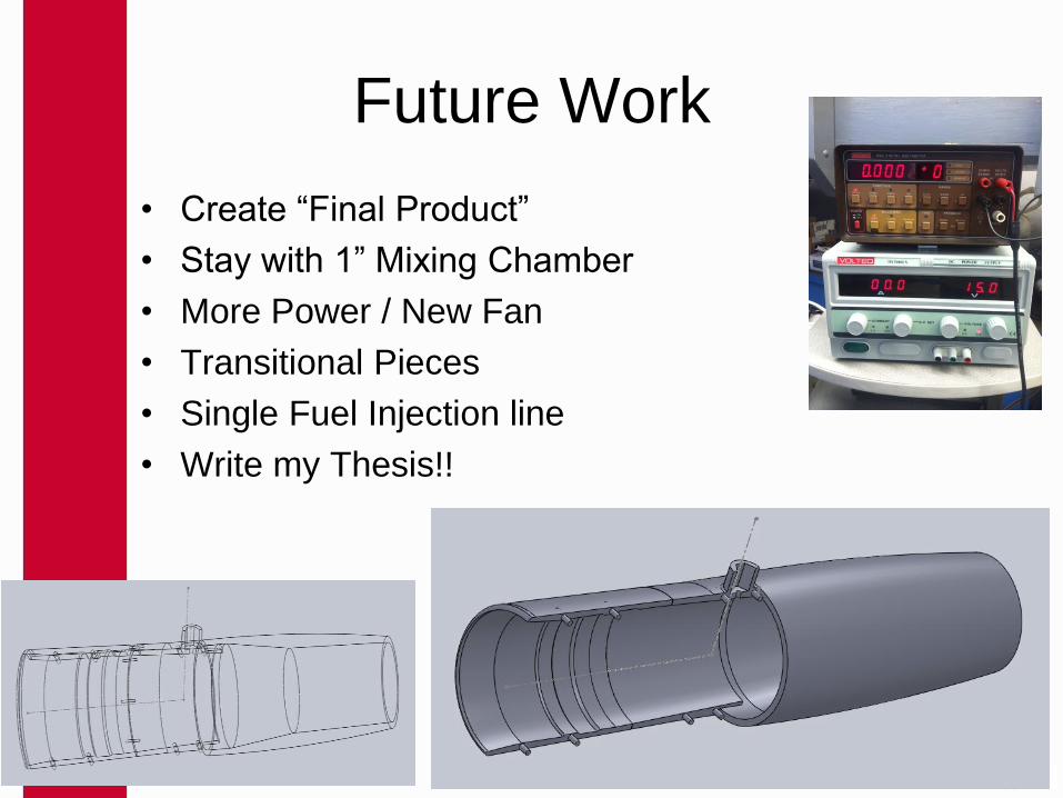
Future Work
• Create “Final Product”
• Stay with 1” Mixing Chamber
• More Power / New Fan
• Transitional Pieces
• Single Fuel Injection line
• Write my Thesis!!

Thank You !!
• I would like to thank the following:
• Dr. Chivey Wu
• Joseph David Wells
• I would like to give special thanks to:
• Dr. Margaret Jefferson
• Dr. Katrina Yamazaki
• LSAMP
• I would to acknowledge our special guest:
• Dr. Lisa Hammersley
• The material presented is based upon work
supported by the National Science Foundation
under Grant #HDR-1246662