LS Variable Frequency DriveLS Variable Frequency … Variable Frequency DriveLS Variable Frequency...
21
LS VFD LS VFD 1 EME Business Div. EME Business Div. LS Variable Frequency Drive
Transcript of LS Variable Frequency DriveLS Variable Frequency … Variable Frequency DriveLS Variable Frequency...
LS VFDLS VFD
1 EME Business Div.EME Business Div.
LS Variable Frequency DriveLS Variable Frequency Drive
LS VFDLS VFD
2 EME Business Div.EME Business Div.
Application
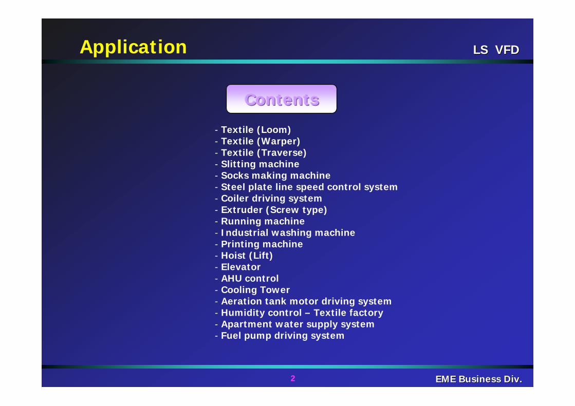
- Textile (Loom)- Textile (Warper)- Textile (Traverse)- Slitting machine- Socks making machine- Steel plate line speed control system- Coiler driving system- Extruder (Screw type)- Running machine- Industrial washing machine- Printing machine- Hoist (Lift)- Elevator- AHU control- Cooling Tower- Aeration tank motor driving system- Humidity control – Textile factory- Apartment water supply system- Fuel pump driving system
ContentsContentsContents
LS VFDLS VFD
3 EME Business Div.EME Business Div.
Textile(Loom)
1. Introduction
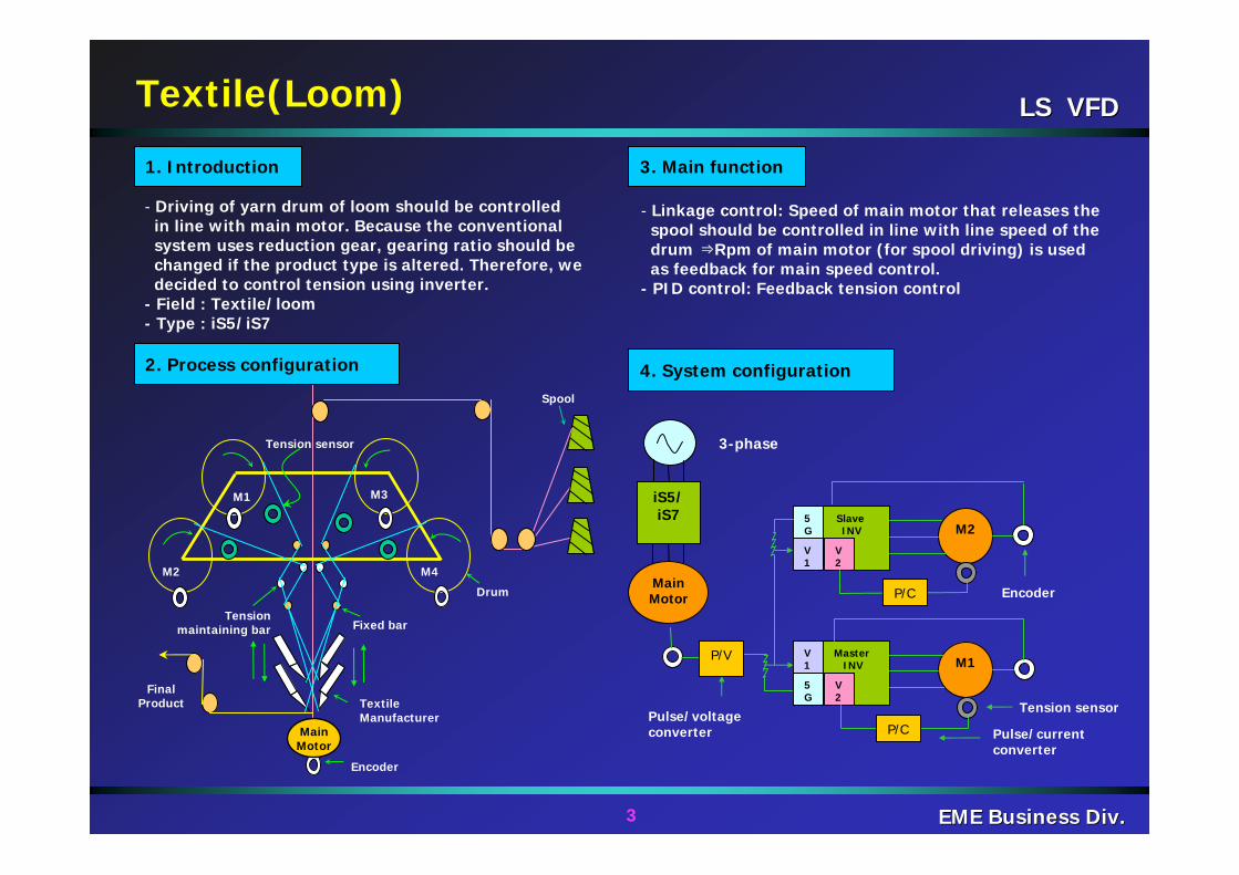
- Driving of yarn drum of loom should be controlledin line with main motor. Because the conventionalsystem uses reduction gear, gearing ratio should bechanged if the product type is altered. Therefore, we decided to control tension using inverter.
- Field : Textile/loom- Type : iS5/iS7
3. Main function
- Linkage control: Speed of main motor that releases thespool should be controlled in line with line speed of thedrum ⇒Rpm of main motor (for spool driving) is usedas feedback for main speed control.
- PID control: Feedback tension control
4. System configuration
M2 M4
M3M1
Drum
Encoder
Final Product Textile
Manufacturer
Tensionmaintaining bar
Spool
Tension sensor
Fixed bar
MainMotor
MasterINV
Slave INV
V1
5G
5G
V1
V2
V2
M1
M2
Pulse/voltage converter
3-phase
iS5/iS7
Main Motor
P/V
P/C Pulse/current converter
P/C
Tension sensor
Encoder
2. Process configuration
LS VFDLS VFD
4 EME Business Div.EME Business Div.
Winding
Threads
Textile(Warper)
1. Introduction
2. Process configuration
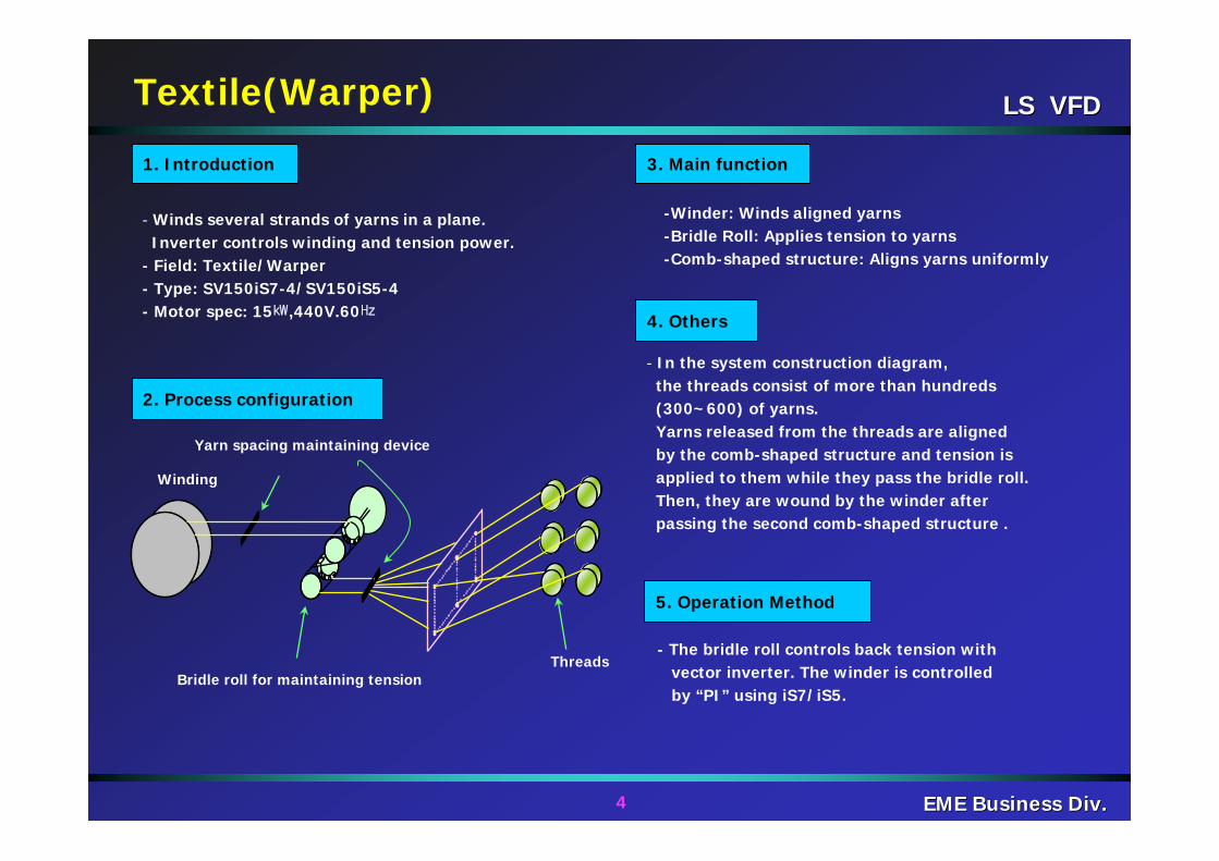
- Winds several strands of yarns in a plane.Inverter controls winding and tension power.
- Field: Textile/Warper- Type: SV150iS7-4/SV150iS5-4- Motor spec: 15㎾,440V.60㎐
Bridle roll for maintaining tension
Yarn spacing maintaining device
3. Main function
-Winder: Winds aligned yarns-Bridle Roll: Applies tension to yarns-Comb-shaped structure: Aligns yarns uniformly
4. Others
- In the system construction diagram,the threads consist of more than hundreds(300~600) of yarns.Yarns released from the threads are alignedby the comb-shaped structure and tension isapplied to them while they pass the bridle roll.Then, they are wound by the winder afterpassing the second comb-shaped structure .
- The bridle roll controls back tension withvector inverter. The winder is controlledby “PI” using iS7/iS5.
5. Operation Method
LS VFDLS VFD
5 EME Business Div.EME Business Div.
yarn
Drum
Cheese
Guide groove Where yarns are
woundFixedGuide
iS5(15kW)
Front ViewSide View
Lint Roving Machine
SpinningMachine Winder
Windercontroller
Clutch
Clutchcontroller
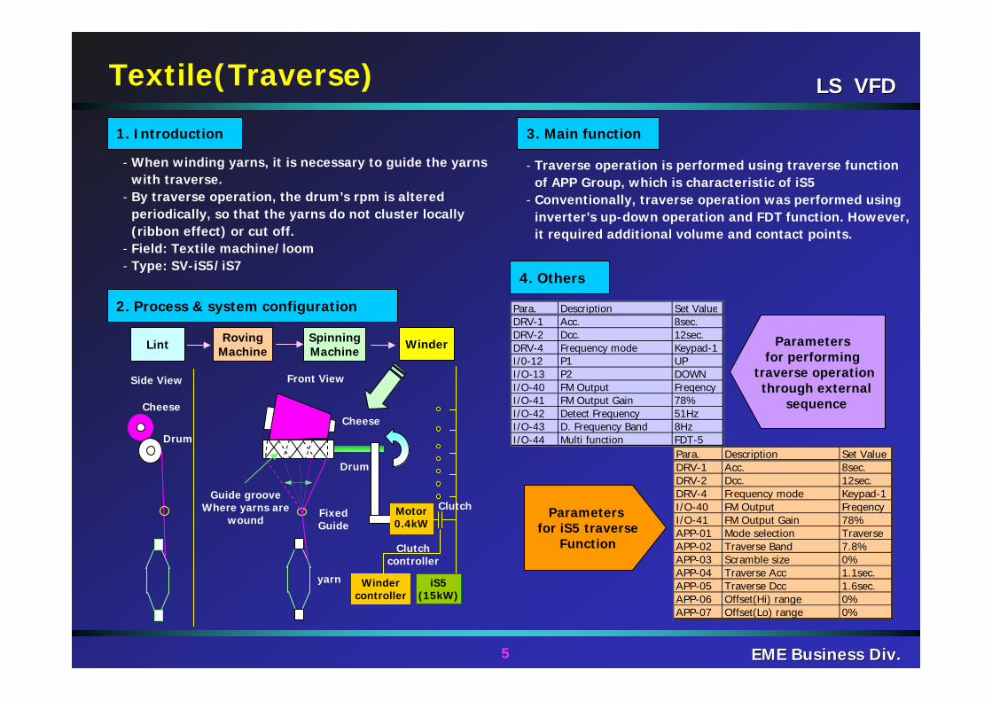
Para. Description Set ValueDRV-1 Acc. 8sec.DRV-2 Dcc. 12sec.DRV-4 Frequency mode Keypad-1I/0-12 P1 UPI/O-13 P2 DOWNI/O-40 FM Output FreqencyI/O-41 FM Output Gain 78%I/O-42 Detect Frequency 51HzI/O-43 D. Frequency Band 8HzI/O-44 Multi function FDT-5
Para. Description Set ValueDRV-1 Acc. 8sec.DRV-2 Dcc. 12sec.DRV-4 Frequency mode Keypad-1I/O-40 FM Output FreqencyI/O-41 FM Output Gain 78%APP-01 Mode selection TraverseAPP-02 Traverse Band 7.8%APP-03 Scramble size 0%APP-04 Traverse Acc 1.1sec.APP-05 Traverse Dcc 1.6sec.APP-06 Offset(Hi) range 0%APP-07 Offset(Lo) range 0%
Parameters for iS5 traverse
Function
Parameters for performing
traverse operationthrough external
sequence
3. Main function
4. Others
- Traverse operation is performed using traverse function of APP Group, which is characteristic of iS5
- Conventionally, traverse operation was performed using inverter’s up-down operation and FDT function. However, it required additional volume and contact points.
- When winding yarns, it is necessary to guide the yarns with traverse.
- By traverse operation, the drum’s rpm is altered periodically, so that the yarns do not cluster locally (ribbon effect) or cut off.
- Field: Textile machine/loom- Type: SV-iS5/iS7
1. Introduction
2. Process & system configuration
Textile(Traverse)
Drum
Cheese
Motor0.4kW
LS VFDLS VFD
6 EME Business Div.EME Business Div.
Looper
Position Sensor 037iS7-2
V1
V2
Pneumatic
V1
V2
V1
V2
Main controller
Main speed control (0~10V)
UnwinderSlittingmachine
Rewinder
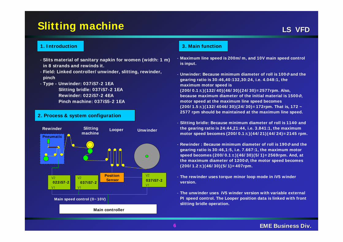
- Slits material of sanitary napkin for women (width: 1 m) in 8 strands and rewinds it.
- Field: Linked controller/unwinder, slitting, rewinder, pinch
- Type - Unwinder: 037iS7-2 1EASlitting bridle: 037iS7-2 1EARewinder: 022iS7-2 4EAPinch machine: 037iS5-2 1EA
2. Process & system configuration
1. Introduction 3. Main function
- Maximum line speed is 200m/m, and 10V main speed control is input.
- Unwinder: Because minimum diameter of roll is 100Φ and the gearing ratio is 30:46,40:132,30:24, i.e. 4.048:1, the maximum motor speed is (200/0.1π)(132/40)(46/30)(24/30)=2577rpm. Also, because maximum diameter of the initial material is 1500Φ, motor speed at the maximum line speed becomes (200/1.5π)(132/4046/30)(24/30)=172rpm. That is, 172 ~ 2577 rpm should be maintained at the maximum line speed.
- Slitting bridle: Because minimum diameter of roll is 114Φ and the gearing ratio is 24:44,21:44, i.e. 3.841:1, the maximum motor speed becomes (200/0.1π)(44/21)(44/24)=2145 rpm.
- Rewinder : Because minimum diameter of roll is 190Φ and the gearing ratio is 30:46,1:5, i.e. 7.667:1, the maximum motor speed becomes (200/0.1π)(46/30)(5/1)=2569rpm. And, at the maximum diameter of 1200Φ, the motor speed becomes (200/1.2π)(46/30)(5/1)=407rpm.
- The rewinder uses torque minor loop mode in iV5 winder version.
- The unwinder uses iV5 winder version with variable external PI speed control. The Looper position data is linked with front slitting bridle operation.
Slitting machine
037iS7-2022iS7-2
LS VFDLS VFD
7 EME Business Div.EME Business Div.
Spool
Socksmanufacturing
DrivingForceTransfer
MotorSocks
iG5A
Socks making machine
2. Process & system configuration
1. Introduction
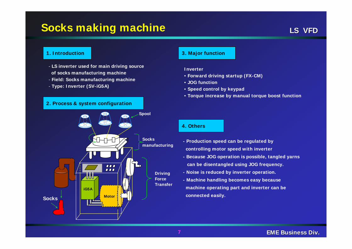
- LS inverter used for main driving source of socks manufacturing machine
- Field: Socks manufacturing machine- Type: Inverter (SV-iG5A)
3. Major function
4. Others
Inverter• Forward driving startup (FX-CM) • JOG function • Speed control by keypad• Torque increase by manual torque boost function
- Production speed can be regulated by
controlling motor speed with inverter
- Because JOG operation is possible, tangled yarns
can be disentangled using JOG frequency.
- Noise is reduced by inverter operation.
- Machine handling becomes easy because
machine operating part and inverter can be
connected easily.
LS VFDLS VFD
8 EME Business Div.EME Business Div.
iS7Steel plate Drum
3Φ
Leveler
Cutting RollSteel plate
Cutter
Steel plate line speed control system
2. Process & system configuration
1. Introduction 3. Major function
4. Others
Steel plate
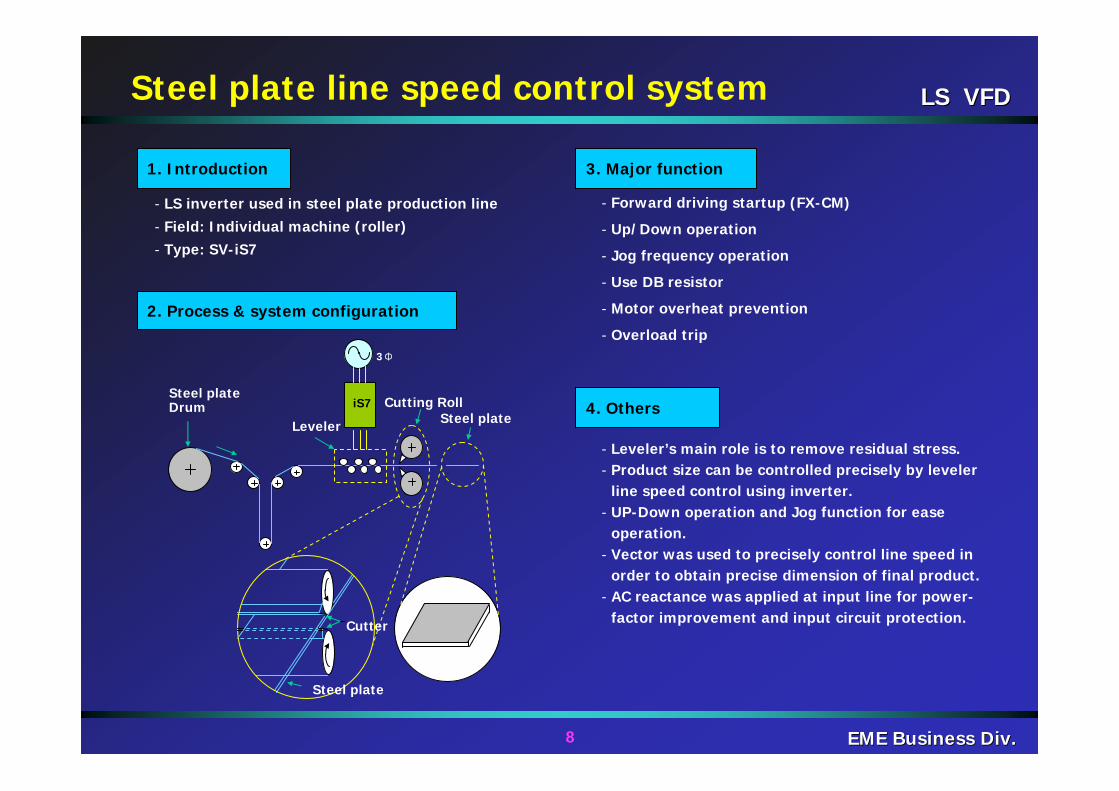
- LS inverter used in steel plate production line- Field: Individual machine (roller)- Type: SV-iS7
- Leveler’s main role is to remove residual stress.- Product size can be controlled precisely by leveler
line speed control using inverter.- UP-Down operation and Jog function for ease
operation.- Vector was used to precisely control line speed in
order to obtain precise dimension of final product.- AC reactance was applied at input line for power-
factor improvement and input circuit protection.
- Forward driving startup (FX-CM)
- Up/Down operation
- Jog frequency operation
- Use DB resistor
- Motor overheat prevention
- Overload trip
LS VFDLS VFD
9 EME Business Div.EME Business Div.
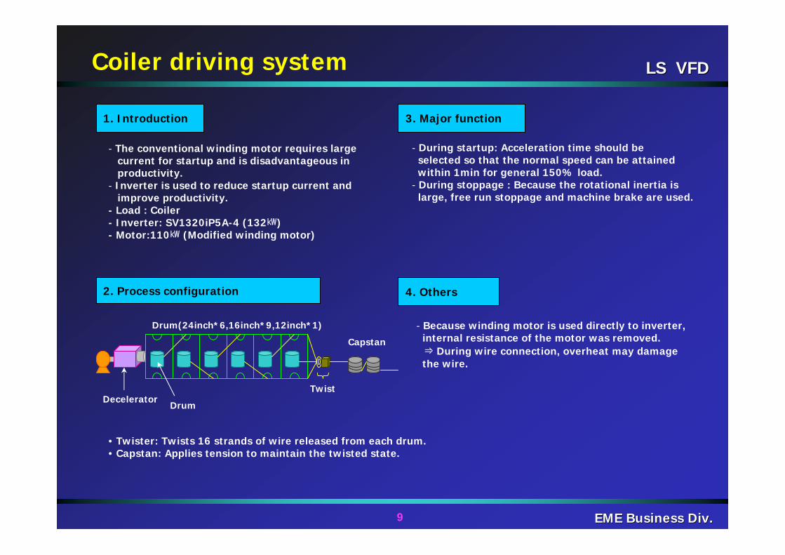
Drum(24inch*6,16inch*9,12inch*1)
Drum
Twist
Capstan
2. Process configuration
1. Introduction 3. Major function
4. Others
Coiler driving system
- The conventional winding motor requires largecurrent for startup and is disadvantageous inproductivity.
- Inverter is used to reduce startup current andimprove productivity.
- Load : Coiler- Inverter: SV1320iP5A-4 (132㎾)- Motor:110㎾ (Modified winding motor)
- During startup: Acceleration time should beselected so that the normal speed can be attainedwithin 1min for general 150% load.
- During stoppage : Because the rotational inertia islarge, free run stoppage and machine brake are used.
• Twister: Twists 16 strands of wire released from each drum.• Capstan: Applies tension to maintain the twisted state.
- Because winding motor is used directly to inverter,internal resistance of the motor was removed.⇒ During wire connection, overheat may damagethe wire.
Decelerator
LS VFDLS VFD
10 EME Business Div.EME Business Div.
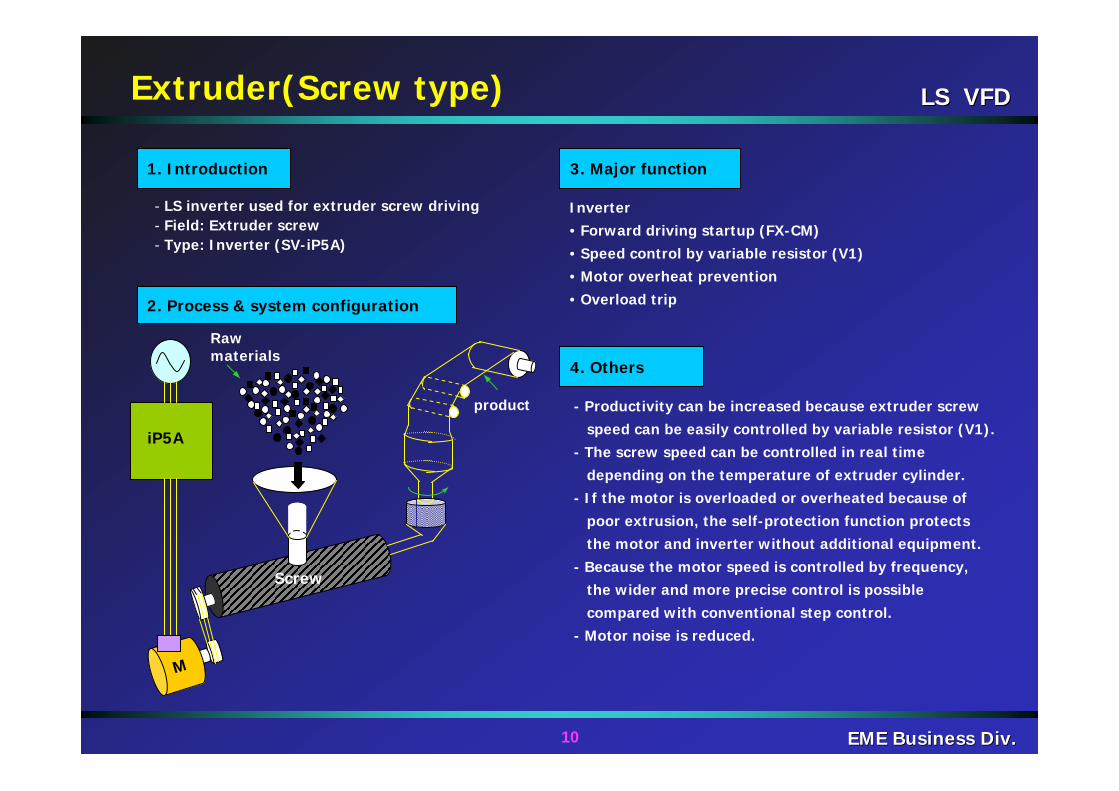
product
M
iP5A
Raw materials
Screw
Extruder(Screw type)
2. Process & system configuration
1. Introduction
- LS inverter used for extruder screw driving- Field: Extruder screw- Type: Inverter (SV-iP5A)
3. Major function
4. Others
Inverter• Forward driving startup (FX-CM) • Speed control by variable resistor (V1) • Motor overheat prevention• Overload trip
- Productivity can be increased because extruder screwspeed can be easily controlled by variable resistor (V1).
- The screw speed can be controlled in real time depending on the temperature of extruder cylinder.
- If the motor is overloaded or overheated because ofpoor extrusion, the self-protection function protectsthe motor and inverter without additional equipment.
- Because the motor speed is controlled by frequency,the wider and more precise control is possiblecompared with conventional step control.
- Motor noise is reduced.
LS VFDLS VFD
11 EME Business Div.EME Business Div.
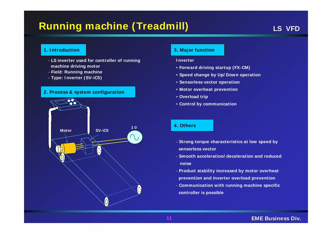
Motor SV-iC51Φ
Running machine (Treadmill)
2. Process & system configuration
1. Introduction 3. Major function
4. Others
- LS inverter used for controller of running machine driving motor
- Field: Running machine- Type: Inverter (SV-iC5)
Inverter
• Forward driving startup (FX-CM)
• Speed change by Up/Down operation
• Sensorless vector operation
• Motor overheat prevention
• Overload trip
• Control by communication
- Strong torque characteristics at low speed by
sensorless vector
- Smooth acceleration/deceleration and reduced
noise
- Product stability increased by motor overheat
prevention and inverter overload prevention
- Communication with running machine specific
controller is possible
LS VFDLS VFD
12 EME Business Div.EME Business Div.
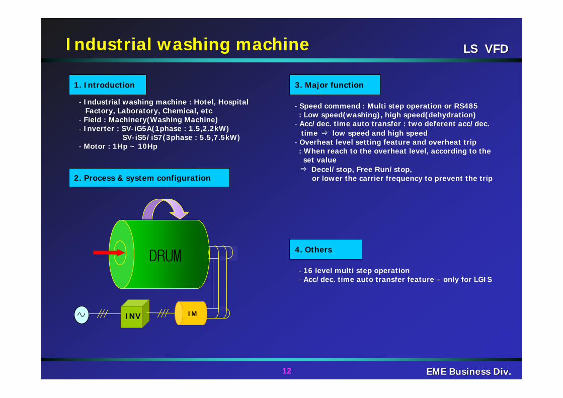
- Industrial washing machine : Hotel, HospitalFactory, Laboratory, Chemical, etc
- Field : Machinery(Washing Machine)- Inverter : SV-iG5A(1phase : 1.5,2.2kW)
SV-iS5/iS7(3phase : 5.5,7.5kW)- Motor : 1Hp ~ 10Hp
- 16 level multi step operation- Acc/dec. time auto transfer feature – only for LGIS
- Speed commend : Multi step operation or RS485: Low speed(washing), high speed(dehydration)
- Acc/dec. time auto transfer : two deferent acc/dec.time ⇒ low speed and high speed
- Overheat level setting feature and overheat trip: When reach to the overheat level, according to the
set value ⇒ Decel/stop, Free Run/stop,
or lower the carrier frequency to prevent the trip
DRUM
INV
Industrial washing machine
IM
2. Process & system configuration
1. Introduction 3. Major function
4. Others
LS VFDLS VFD
13 EME Business Div.EME Business Div.
EiS7
Encoder
Gear
Tension Controller
0~10VVolumeresistor
2nd colorprinting
1st colorprinting
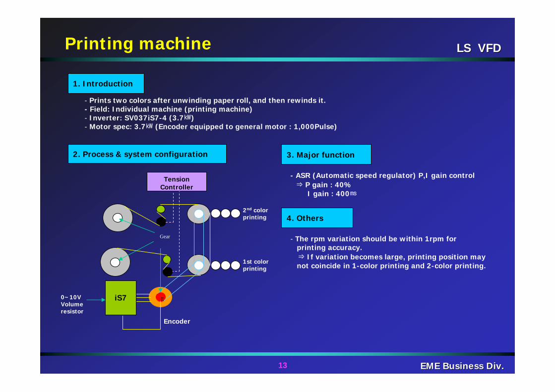
2. Process & system configuration
1. Introduction
3. Major function
4. Others
- Prints two colors after unwinding paper roll, and then rewinds it.- Field: Individual machine (printing machine)- Inverter: SV037iS7-4 (3.7㎾)- Motor spec: 3.7㎾ (Encoder equipped to general motor : 1,000Pulse)
- The rpm variation should be within 1rpm forprinting accuracy.⇒ If variation becomes large, printing position maynot coincide in 1-color printing and 2-color printing.
- ASR (Automatic speed regulator) P,I gain control⇒ P gain : 40%
I gain : 400㎳
Printing machine
LS VFDLS VFD
14 EME Business Div.EME Business Div.
Rack & pinion
Lighting tower
~
AXA, AXCRun signal
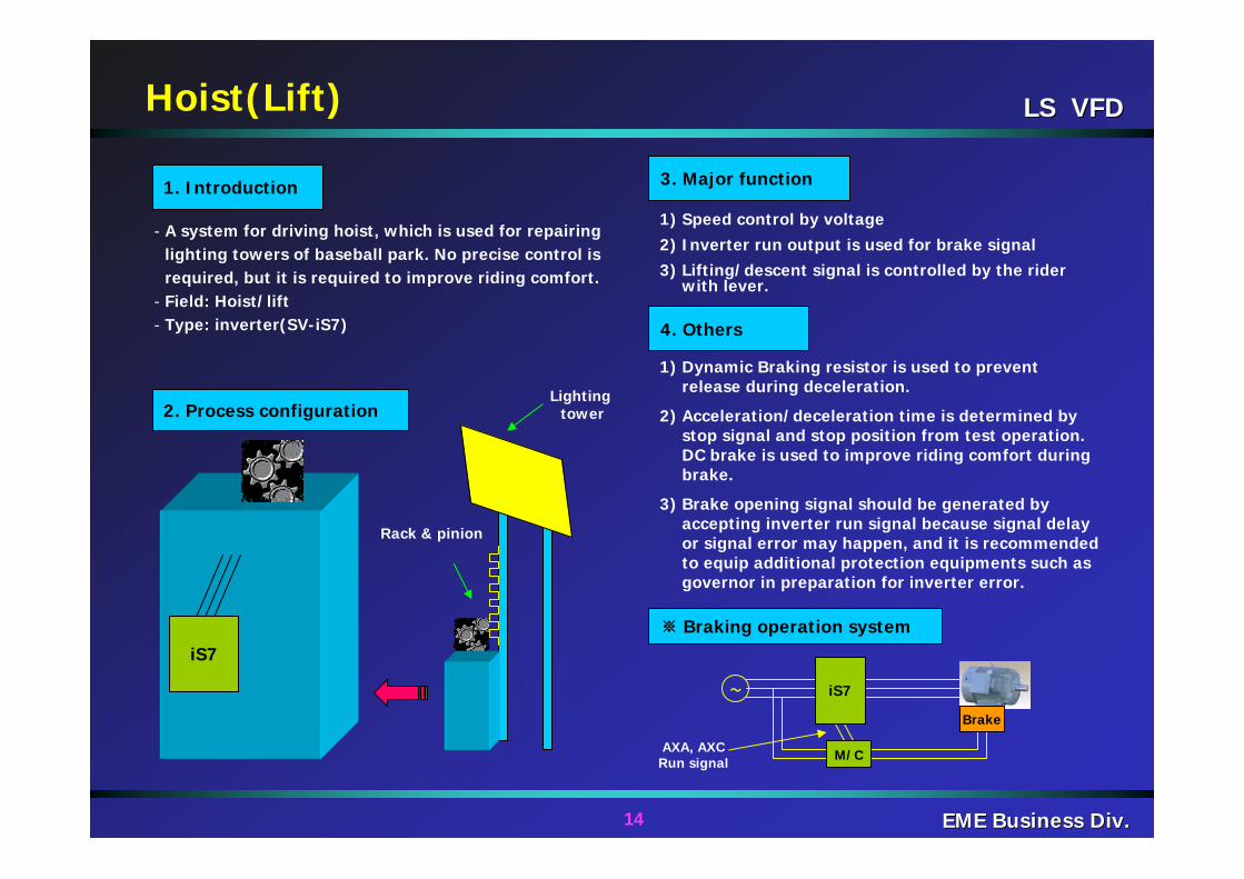
※ Braking operation system
- A system for driving hoist, which is used for repairing lighting towers of baseball park. No precise control is required, but it is required to improve riding comfort.
- Field: Hoist/lift- Type: inverter(SV-iS7)
2. Process configuration
1. Introduction
1) Speed control by voltage2) Inverter run output is used for brake signal3) Lifting/descent signal is controlled by the rider
with lever.
3. Major function
M/C
Brake
4. Others
1) Dynamic Braking resistor is used to prevent release during deceleration.
2) Acceleration/deceleration time is determined by stop signal and stop position from test operation. DC brake is used to improve riding comfort during brake.
3) Brake opening signal should be generated by accepting inverter run signal because signal delay or signal error may happen, and it is recommended to equip additional protection equipments such as governor in preparation for inverter error.
Hoist(Lift)
iS7
iS7
LS VFDLS VFD
15 EME Business Div.EME Business Div.
iV5 M
Electronic Brake
encoder
Counter Weight
CarSensor
Elevator
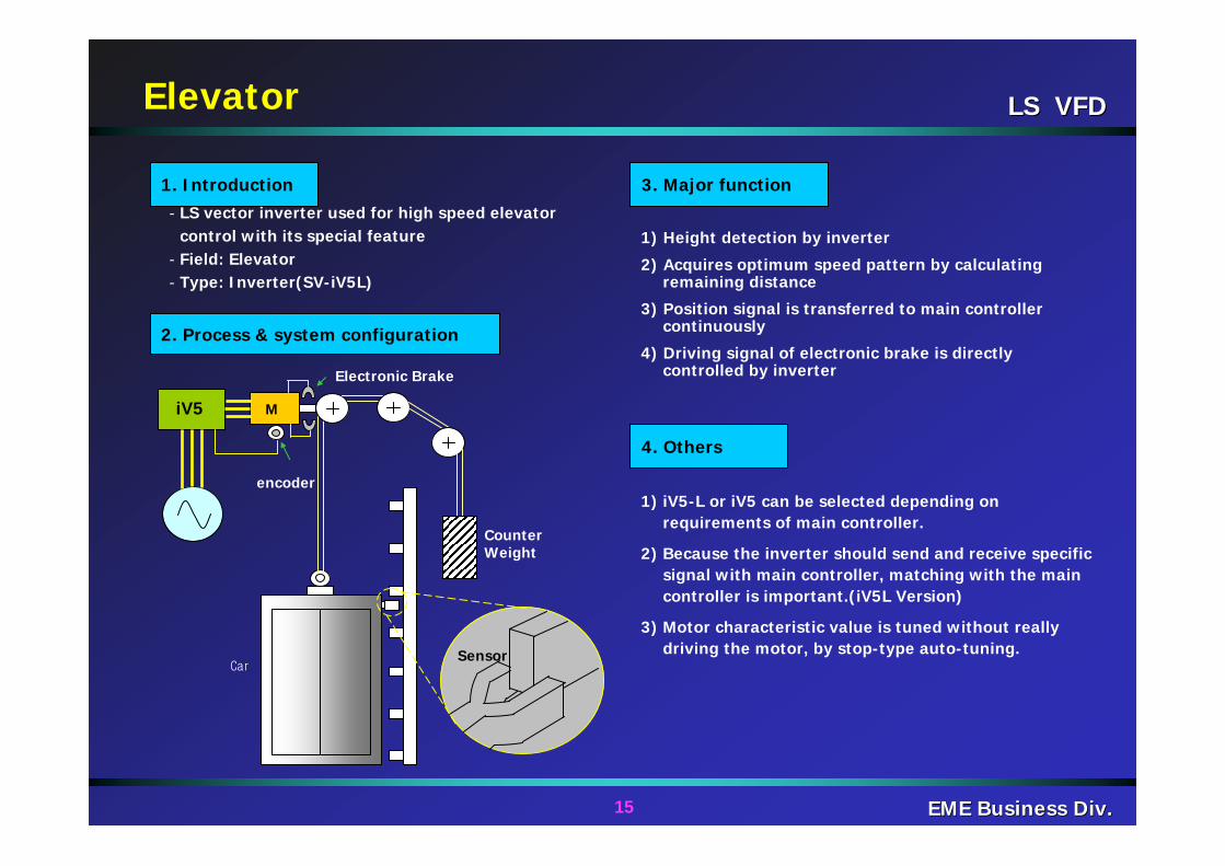
2. Process & system configuration
1. Introduction- LS vector inverter used for high speed elevator
control with its special feature- Field: Elevator- Type: Inverter(SV-iV5L)
3. Major function
4. Others
1) Height detection by inverter
2) Acquires optimum speed pattern by calculating remaining distance
3) Position signal is transferred to main controller continuously
4) Driving signal of electronic brake is directly controlled by inverter
1) iV5-L or iV5 can be selected depending on requirements of main controller.
2) Because the inverter should send and receive specific signal with main controller, matching with the main controller is important.(iV5L Version)
3) Motor characteristic value is tuned without really driving the motor, by stop-type auto-tuning.
LS VFDLS VFD
16 EME Business Div.EME Business Div.
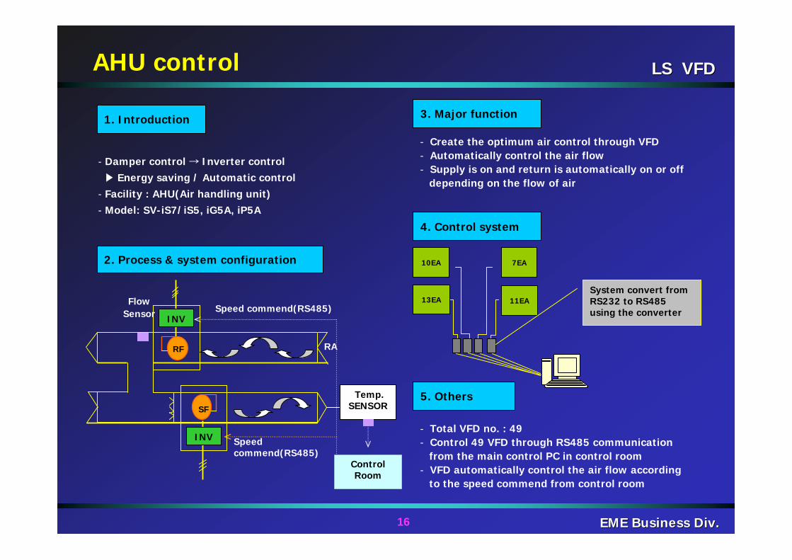
- Damper control → Inverter control▶ Energy saving / Automatic control
- Facility : AHU(Air handling unit)- Model: SV-iS7/iS5, iG5A, iP5A
3. Major function
- Create the optimum air control through VFD- Automatically control the air flow- Supply is on and return is automatically on or off
depending on the flow of air
4. Control system
10EA 7EA
13EA 11EASystem convert from RS232 to RS485 using the converter
5. Others
- Total VFD no. : 49- Control 49 VFD through RS485 communication
from the main control PC in control room- VFD automatically control the air flow according
to the speed commend from control room
AHU control
SF
RF
INVSpeed commend(RS485)
RA
Control Room
Temp.SENSOR
Flow Sensor
INV Speed commend(RS485)
1. Introduction
2. Process & system configuration
LS VFDLS VFD
17 EME Business Div.EME Business Div.
PID
TemperatureSensor
V1
<PID Control>
V1 Display
VariableResistor
Cooling water
Cooling Tower
FAN
Cooling Tower
2. Process configuration
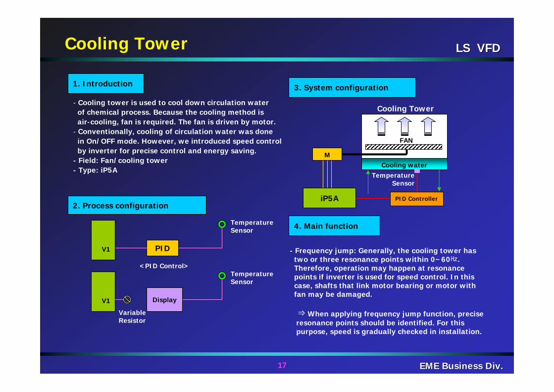
1. Introduction
- Cooling tower is used to cool down circulation waterof chemical process. Because the cooling method isair-cooling, fan is required. The fan is driven by motor.
- Conventionally, cooling of circulation water was donein On/OFF mode. However, we introduced speed controlby inverter for precise control and energy saving.
- Field: Fan/cooling tower- Type: iP5A
TemperatureSensor
TemperatureSensor
3. System configuration
4. Main function
PID Controller
- Frequency jump: Generally, the cooling tower has two or three resonance points within 0~60㎐. Therefore, operation may happen at resonancepoints if inverter is used for speed control. In thiscase, shafts that link motor bearing or motor withfan may be damaged.
⇒When applying frequency jump function, preciseresonance points should be identified. For thispurpose, speed is gradually checked in installation.
M
iP5A

LS VFDLS VFD
18 EME Business Div.EME Business Div.
Power(㎾)
Aeration tank motor driving
1. Introduction
2. Process & system configuration
M
iP5APID
Control
Air bubble
Water Concentration
detection
Blower
3. Major function
4. Others
- DO(dissolved Oxygen) of water is controlled forrapid reaction of pollutants and chemicals.
- Inverter is used for speed control.- Inverter is used for precise control and
energy saving.- Field: Blower/aeration tank- Type: SV750iP5A-4(75㎾)- Motor spec: 75㎾, 2-pole
- PID control is used to precisely controlwater concentration.
- Even the blower is energy-saving load, energyis not saved if aeration tank is the main load.⇒ Pressure is applied to the blower of aeration tankbecause it is positioned in water. Therefore, a large
torque is required to overcome the pressure and expelair bubble. Here, the water pressure acts as damper.
< Load amount vs. Power consumption >
Load(blow or flow volume)
General energy saving characteristic curve
Damper control and aeration tank characteristic curve
LS VFDLS VFD
19 EME Business Div.EME Business Div.
Factory
Room
Humidity feedback
Sensor
Additional Sensor
Speed commend
Humidity control – Textile factory
2. Process & system configuration
1. Introduction
3. Major function
4. Others
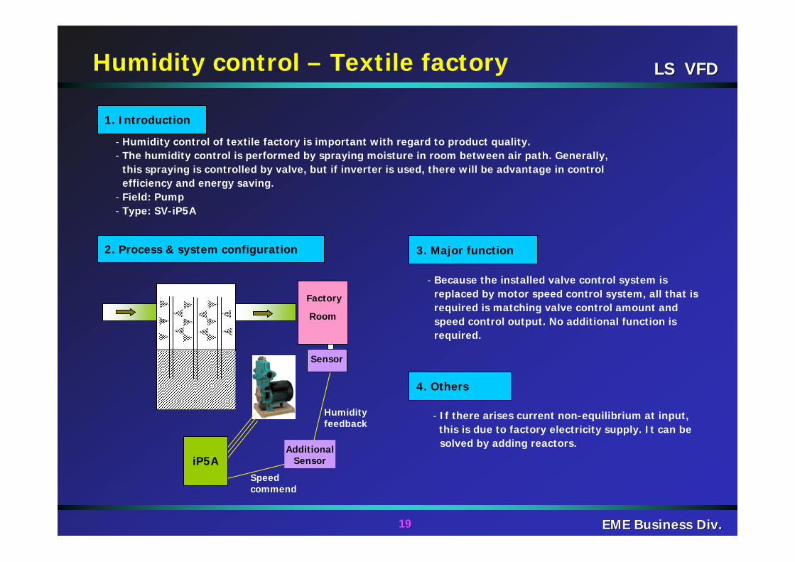
- Humidity control of textile factory is important with regard to product quality.- The humidity control is performed by spraying moisture in room between air path. Generally,
this spraying is controlled by valve, but if inverter is used, there will be advantage in control efficiency and energy saving.
- Field: Pump- Type: SV-iP5A
- If there arises current non-equilibrium at input, this is due to factory electricity supply. It can be solved by adding reactors.
- Because the installed valve control system is replaced by motor speed control system, all that is required is matching valve control amount and speed control output. No additional function is required.
iP5A
LS VFDLS VFD
20 EME Business Div.EME Business Div.
Apartment (12~18F)
6 buildings / 860 households
Pressure gauge
P1
Underground water tank
P2 P3 P4
PLC
IP5A
2. Process & system configuration
1. Introduction 3. Major function
4. Others
Apartment water supply system
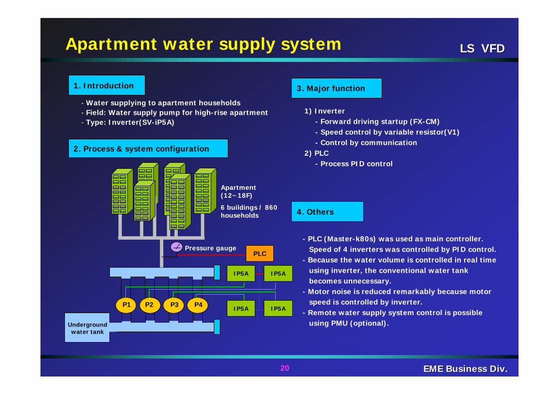
- Water supplying to apartment households- Field: Water supply pump for high-rise apartment- Type: Inverter(SV-iP5A)
1) Inverter- Forward driving startup (FX-CM) - Speed control by variable resistor(V1)- Control by communication
2) PLC- Process PID control
- PLC (Master-k80s) was used as main controller.Speed of 4 inverters was controlled by PID control.
- Because the water volume is controlled in real timeusing inverter, the conventional water tankbecomes unnecessary.
- Motor noise is reduced remarkably because motorspeed is controlled by inverter.
- Remote water supply system control is possibleusing PMU (optional).
IP5A
IP5A
IP5A
LS VFDLS VFD
21 EME Business Div.EME Business Div.
P
P
P
P
Pressure signalTransfer
4~20mAINPUT
4~20mA
DCS Control System
Fuel pump driving system
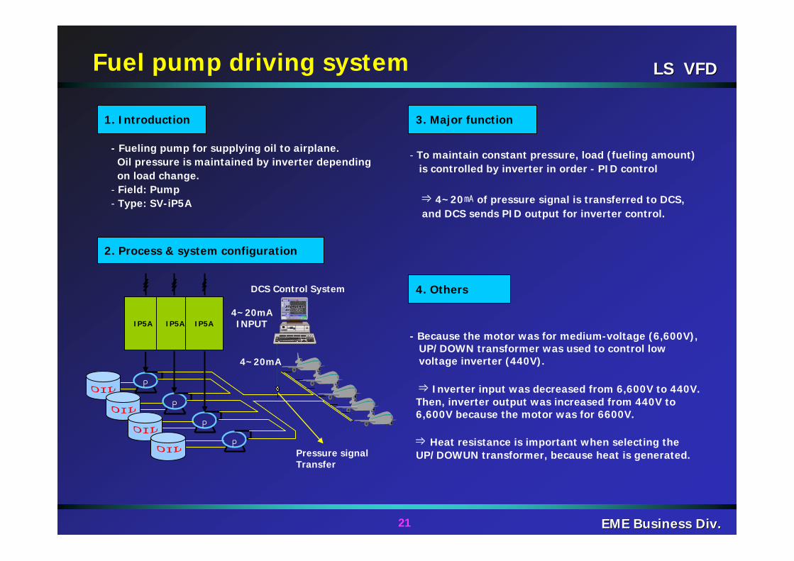
- Fueling pump for supplying oil to airplane.Oil pressure is maintained by inverter dependingon load change.
- Field: Pump- Type: SV-iP5A
- To maintain constant pressure, load (fueling amount)is controlled by inverter in order - PID control
⇒ 4~20㎃ of pressure signal is transferred to DCS, and DCS sends PID output for inverter control.
- Because the motor was for medium-voltage (6,600V),UP/DOWN transformer was used to control lowvoltage inverter (440V).
⇒ Inverter input was decreased from 6,600V to 440V. Then, inverter output was increased from 440V to6,600V because the motor was for 6600V.
⇒ Heat resistance is important when selecting theUP/DOWUN transformer, because heat is generated.
2. Process & system configuration
1. Introduction 3. Major function
4. Others
IP5A IP5A IP5A