
LRGCC 2018 Fundamentals...Mist extractors include mesh and vane type. Mesh type provide a thin wire...
49
LRGCC 2018 Fundamentals Fundamentals of Separation of Gases, Liquids, and Solids Presented by Pierre Crevier – Crevier Process Consulting, Darryl Mamrosh – Trimeric Corporation
Transcript of LRGCC 2018 Fundamentals...Mist extractors include mesh and vane type. Mesh type provide a thin wire...

LRGCC 2018 Fundamentals
Fundamentals of Separation of Gases, Liquids, and Solids
Presented by Pierre Crevier – Crevier Process Consulting, Darryl Mamrosh – Trimeric Corporation
FUNDAMENTALS OF SEPARATION OF GASES, LIQUIDS, AND SOLIDS
T. R. Bacon
INTRODUCTION The separation of liquids from gases, liquids from liquids, and solids from gases and liquids occurs repeatedly throughout natural gas processing and oil refining. Although the separation vessels have different names and configurations, many of the principles of design are common.
The objective of this article is to review the theory, design, and applications of the various equipment and discuss troubleshooting problems encountered for the separation of liquids from a gas. It is an edited rewrite of Fundamentals of Separation 1999 Edition used in the Laurance Reid Gas Conditioning Conference. There are a number of excellent references in the bibliography 1, 2, 3, 4, 5, 6.
SEPARATOR APPLICATIONS One of the most common functions of a separator is to separate and remove oil and/or water from gas. The separations becomes necessary when one of the following requirements exists:
Interception Separation of a liquid from a gas to reduce the load in downstream equipment or reduce slugging effects. • Lease field separators separating produced oil, water, and gas.• Pipeline separators and traps removing flow induced slugs of liquids.
Recovery Low cost recovery of a liquid product • Wellhead separators removing produced oil and water from gas.• Plant inlet separator• Hydrocarbon distillation reflux accumulators.• Refrigeration system receivers.
Prevention/Protection Separation of undesired liquid before it enters a unit operation. •Removal of liquid hydrocarbons in a gas prior to amine treating to prevent foaming.• Prevention of liquids entering a gas compressor.• Flashing hydrocarbons from a rich amine to prevent poor quality Claus sulfur.

VESSEL NOMENCLATURE The nomenclature of separation vessels is not consistent and reflects more the variety in colloquial convention rather than a theoretical definition of the purpose of each. The following nomenclature is used frequently in describing the various types of separation vessels: Separator A general term for any separation vessel. For example a vessel used in the field to remove well head liquids from gas.
Knockout This usually refers to an empty vessel without additional internal separation aids. For example, two or three phase removal of oil and water from a gas.
Scrubber Designed for high gas/liquid ratios, these are often used ahead of dehydrators, extraction plants, compressors, and amine units to remove incidental liquids before the gas is further processed. An alternate convention describes a vessel using a circulating liquid to wet scrub particles from a gas.
Trap or Line Drip Designed for very high gas/liquid ratios in a gas pipeline. Normally no flow of liquids but it provides a place to collect and remove any free liquid.
Slug Catcher Designed for occasional to frequent liquid slugs in a gas pipeline. These remove large liquid volumes generated in a pipeline flow at irregular intervals. Coalescing Filter/Separator Designed for very high gas/liquid ratios and small micron liquid entrainment. These usually have two compartments. The first has filter coalescing elements which coalesce small drops into larger ones which are more readily removed with mist extractors in the second compartment. Dry Gas Filter Designed to primarily remove dry dust from a gas. The filter elements are actually the separating device.
Liquid/Liquid Separator Designed for hydrocarbon/aqueous phase separation. A typical application separates aqueous amine or caustic streams from liquid hydrocarbons.

Flash Tank Designed for liquids with entrained and saturated gas when a pressure let-down creates flashing vapors that require removal. The flash tank may provide either two or three phase separation depending on the liquid phase content. Additional residence time is often a requirement to allow for degassing or separation of two liquid phases.
Three Phase Separator Designed for gas with significant oil and water that requires separation before processing or disposal. Separates gas from the liquid phase and allows the liquid phase to separate further into hydrocarbon and aqueous phase before removal.
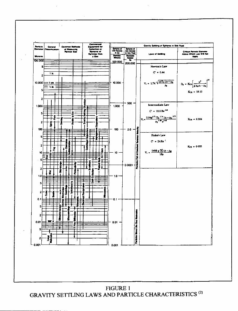
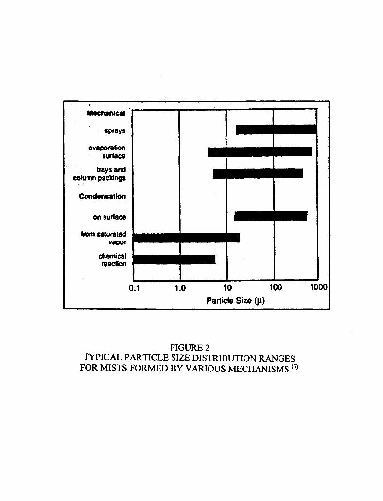
Trayed towers Designed to separate gas and liquids in sequential mass transfer stages. The intimate contact of gas and liquids to allow for close approach to equilibrium for mass transfer of components between phases requires adequate separation of the two prior to entry to the next mass transfer stage in order to maintain adequate mass transfer efficiency in distillation and absorption/stripping. THEORY Particle Characteristics The attached Figure 1 2, Gravity Settling Laws and Particle Characteristics, provides a comparison of droplet size to particles commonly recognized in the General Classification column. Visible characteristics are compared to particle diameter in microns (0.001 mm). A general classification separates rain, 100 microns and larger, from fog, 1 to 100 microns, and smoke, less than 1 micron. Figure 2 7 compares typical particle size distribution ranges for mists formed by various mechanisms. The desired droplet size to be removed varies with the application. A general classification is the following: Application Particle diameter, micron Secondary separation in high gas/liquid streams 500 Flare or Vent scrubbers without mist eliminators 300 � 500 Secondary separation in low gas/liquid streams 100 Mist elimination 10 Requiring chemical or electrostatic removal < 0.1
Gravity
Gas, Liquid, and Solid phases will separate from each other by difference in the specific gravity of each phase. The closer the specific gravities, the less driving force for separation. Liquid droplets will settle out of a gas phase if the gravitational force acting on the drop is greater than the drag force of the gas flowing around the droplet tending to
carry it in the direction of the gas flow. The separation performance is influenced by the particle size, the particle density relative to the suspension medium, and the viscosity of the suspension medium. For water suspended in air, those particles 50 microns and larger, will settle by gravity independent from turbulent effects. As turbulence increases or the relative density decreases, larger particle diameters are necessary for gravity settling. When the particle size is less than 50 microns, gravity is no longer effective and mechanical assistance such as centrifugal force is necessary. Particles less than 5 microns require additional effects including coalescing, filtration, reduction of settling distance, liquid scrubbing, or electrostatic precipitation. Momentum A moving particle suspended in a gas stream will tend to maintain its direction of movement unless there is a force large enough and in a direction other than the gas flow to change it. One example is the force of gravity acting on a particle suspended in the gas flow through a horizontal separator and tending to drag it down. Another example is the result of sharply changing the direction of gas flow while the particle continues in the original direction. The force required to change the direction of the particle increases as its mass increases. Thus a small force will deflect gas more readily than a liquid or solid particle and similarly will deflect a small liquid particle more readily than a larger liquid particle. Changing directions alters the path of the gas while the liquid continues in a straight line. Inlet geometry can therefore be used to provide the initial separation of phases based on their relative momentum.
Solubility Gas, Liquid, and Solid phases will separate from each other only to the extent that each has a limited solubility in the other. The equilibrium solubility of liquids in a gas, liquids in liquids, or solids in liquids determines these limits. Thus, removal of heavier hydrocarbons in a hydrocarbon gas solely by separation is limited by the equilibrium solubility of the heavies in the gas. Separation of two immiscible liquid phases is limited by the mutual solubility of the two. Separation of a solid from a liquid is limited by the extent of dissolution of the solid in the liquid.
Temperature and Pressure Effects The physical properties of the phases are affected by the temperature and pressure at separation. Higher temperature favors gas/liquid separation because it decreases gas gravity more so than liquid gravity. Higher pressure hinders gas/liquid separation because it increases gas gravity without markedly affecting liquid gravity. The approach to the critical point eliminates differentiating characteristics of the two phases. Higher temperature and higher pressure hinder phase separation because they generally tend to increase solubilities.

Coalescing When particles of similar liquid are given the opportunity to collide they will coalesce and become one mass. On a macro scale, this is obvious and instant. As droplet size decreases, the surface tension forces that create the droplet can offer resistance to coalescence, ultimately to the degree that particles of small, similar size may even oppose each other. Low surface tension tends to hinder coalescing. A high viscosity also hinders coalescing. Reducing these forces permits coalescing to form larger droplets having adequate differential properties to afford separation from the light phase. Chemical treatment is often effective in providing better separation by reducing foaming and emulsion. Alternately, combining the effect of particle momentum and a surface for the particles to impinge and coalesce results in improved separation. Coalescing may occur in the primary section of the separator, as in the case of a coalescing filter separator, or it may be used in the final mist extraction section to polish the total removal effect.
Efficiency The efficiency of phase separation can be judged as broadly as preventing a compressor cylinder failure due to injested liquids. In other cases, problems caused by contamination of downstream process may require efficiencies of 99.9% removal of particles greater than a specified micron size. To be specific, the droplet size and the percent removal must be specified.
VESSEL FEATURES
Primary Separation The design of the multiple phase entry into the separator provides a bulk separation of liquid slugs and larger liquid particles and improves the effectiveness of subsequent features. Entry devices usually use directional change of flow to absorb momentum and provide an initial bulk removal of the heavy phase. Afterwards, internal baffles may be used to calm the flow in preparation for settling.
Secondary Separation The body of the separator is used for major separation of remaining particles by gravity in preparation for the final polishing in the mist eliminator. This requires reduced turbulence and velocity. Experience notes that if 100 micron droplets are removed here, the mist eliminator will not be flooded and will perform its job of removing droplets in the 10 to 100 micron diameter The settling direction relative to the light phase flow affects the net effect. Thus, liquid particles settling downward through an upward flowing gas encountered in a vertical separator experience more resistance to settling than those settling downward through a horizontal flowing gas, encountered in a horizontal separator.

Coalescing When greater separation efficiency is needed than primary and secondary can provide, coalescing separation techniques are used after settling. Coalescing devices and mist extractors reduce the distance a particle must travel before encountering an impingement and coalescing surface. Occasionally, centrifugal devices will be employed to achieve the same results. Typical removal includes removal of 99% of particles down to 10 micron. Mist extractors include mesh and vane type. Mesh type provide a thin wire pad, typically 4 to 6 inches thick of specified mesh density (usually 10 � 12 lb./cu. Ft), for an impingement surface to coalesce liquid droplets which then are large enough to fall to the liquid surge section. Occasionally a synthetic fiber is included in the mesh for additional effect. The gas velocity through the wire mesh must be low enough to prevent re-entrainment of the coalesced droplets. Typical carryover from a mist extractor is less than 0.1 gal/MMSCF. Typical pressure drop through the wire mesh is less than 1 in. H2O. Vane type coalescers provide an extended surface angled to the normal gas flow for impingement and coalescing and a channel protected from the gas velocity to return the liquid to the surge section. Vane mist extractors provide performance similar to wire mesh but they don�t plug as readily and require less area than wire mesh. However, they have a limited turndown rate before efficiency drops off. Filter separators handle modest primary and secondary separation in the first section of the separator followed by filter cartridges that coalesce liquid particles as the gas flows from outside to inside the filter. A mist extractor recovers the coalesced particles in the second section. In this application, the filters do not restrain the phase being separated, but rather provide the surface for coalescing as the phase passes through the filter cartridge. The filter separator has higher efficiency than centrifugal elements, for example removing 100 % of particles greater than 8 microns and 99.5% of those from 0.5 to 8 microns in diameter. Filter separators will effectively remove solids 3 microns or smaller from the gas as long as the liquid is either absent or adequate to wash the cartridge surface. Otherwise, the liquid can create a paste on the outside of the cartridges that quickly blocks the flow and can cause collapse of the cartridge due to high pressure drop. Pressure drop through clean, dry cartridges is normally less than 1 psi and the cartridges should be changed at about 10 psi. Centrifugal effect, or multi-cyclone devices can be installed to improve removal efficiency. They have an advantage over filters in their ability to remove solids as well as liquids. They require less maintenance than filter elements and can have as good or better efficiency as vanes, but they do have the following limits: 1. Some designs do not handle slugs well. 2. The pressure drop is higher than vane or clean wire mesh types. 3. The operating flow range for highest efficiency is narrow.
Liquid Accumulation A reservoir of liquid serves to allow for degassing of the liquid with minimum disturbance from gas flow and adequate retention time for gas break out. It also provides a surge volume to moderate the effect of varying liquid flows on the level control. A vortex breaker in the liquid outlet reduces gas entrainment in the exiting liquid caused by vortex action. Degassing will be better in a horizontal separator with a shallow liquid level. Emulsion separation may require higher temperature, higher liquid level, and/or the use of an emulsion breaking chemical.
Instrumentation and Controls The minimum control requirement is liquid level control of the surge volume. A nominally simple control, its actual requirements can be quite demanding. A normally dry separator will often leak more liquid through the level control valve than the liquid load, causing loss of gas. An on-off or differential gap controller helps overcome this problem. A separator with widely varying liquid load must control over the extended range. An equal percentage trim level control valve would be appropriate for this application. Liquid/liquid separators need a liquid interface level control. Separators often have a back pressure control valve on the gas outlet whose performance affects the separation efficiency. Pressure and temperature gauges may also be incorporated. If fouling is an issue and a mist extractor is used, a differential pressure gage will aid in diagnosing fouling problems.
Configuration There are several options for separator configuration. Factors that influence the design decision include the following: 1. Will the application have to contend with solids mixed with the liquid and gas? 2. Is plot plan footprint area critical? 3. Are there any transportation limitations? 4. Are heating coils or cleaning jets a consideration? 5. Is there a need for high degassing surface area? 6. Is there a need for high liquid surge volume? 7. Is there a need for high liquid retention time?
The initial choice of configuration is between vertical or horizontal design. Although disagreements exist, some of the advantages of each are shown in Table 2: Vertical separators (Figure 3) may be better suited for handling liquid slugging and unsteady flows if liquid surge capacity can be adjusted in design by varying the height. This height can also be used to accommodate more foam height. Level control has a fast response and the absolute level is not critical to the separation efficiency. There is less chance of re-entraining liquids. They do require larger diameter than horizontal
separators for settling. They can be adapted for removal of a small volume of immiscible third phase liquid. Mist extractors can significantly reduce the design diameter.
Horizontal, Single Barrel separators (Figure 4 and 4a) require design for both gas and liquid capacity in the same diameter. They are better suited for large volumes of total fluids and large amounts of dissolved gases where the flows are steady. The design diameter needed for settling can be smaller, however, the portion of vessel diameter dedicated to liquid surge must be subtracted from that remaining for gas flowing area. They have a larger gas/liquid interface for vapor disengagement. They might be able to handle foam better than vertical separators given the additional surface area, however, this same trait provides greater opportunity for re-entraining liquids. They have less surge capacity than vertical separators and there is a slower response to level control whose absolute level is more critical to the separation efficiency. They are most easily adapted for three phase separation.
Horizontal, Double Barrel separators (Figure 5) allow design for gas and liquid capacity in two separate diameters. With the two functions, gas capacity and liquid surge separated, a slightly smaller vessel may be designed compared to the horizontal single barrel. They are suitable for gases with very low liquid rates. They also allow special features such as coalescing filters to be added and eliminate re-entrainment of liquids.
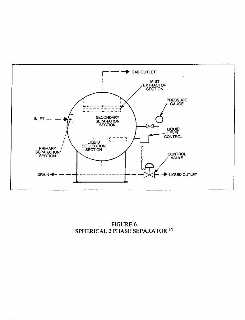
Spherical separators (Figure 6) are compact and may be less expensive. They have limited surge capacity and are limited as to secondary separation features. The have inadequate room for three phase separation. These enjoyed a bit of popularity in earlier days, but are not frequently seen today. DESIGN The design of a separator consists of selecting a type of separator, selecting the additional separation features required, sizing for gas capacity, sizing for liquid capacity, and determining the height or length necessary for adequate performance.
Criteria The design of separators is based on the following information: 1. Flows of gas, liquid, and solids entering the separator. 2. Compositions of each stream. 3. Temperature and pressure at separation. 4. The characteristics of the flows: mist, free liquid, slugs, flashing vapor, maximum,
normal, minimum flow rates. 5. The specifications for the exit streams, ie, the allowable content of a minimum
particle size.
Gas Capacity The gas capacity of a separator is designed for a specified gas rate. This may be specified as a maximum or a normal rate. Depending on the relative magnitude and frequency of the maximum to the normal rate and the consequences of over ranging, one or the other should be the determining criteria for calculating the maximum allowable gas velocity to

permit the desired separation of gas and liquid. Equations have been developed to relate the maximum allowable velocity permissible for particles of a specified diameter to separate from the suspension medium to the viscosity, densities, and the force of gravity of the system. The diameter of the separator is then calculated to limit the superficial gas velocity at the selected design gas rate. It should be noted that the calculations assume a uniform gas velocity across the separator diameter. Gas channeling creates uneven gas flow distribution across the separator diameter and can result in poor performance even though the calculations say it should work. Free Settling Velocity Liquid droplets will settle out of a gas phase if the gravitational force acting on the droplet is greater than the buoyant drag force of the gas flowing around the droplet. Smaller particles require a lower settling velocity. The gravitational force on a particle is determined from the equation: FG = C�Apρg(Vt
2/2g) Eq. 1 The buoyant drag force on a sphere from Archimedes� principles is: FB = (ρl - ρg)πDp
3/6 Eq. 2 When the gravitational force on a particle is equal to the buoyant drag force, the particle�s acceleration is zero and it moves at a constant velocity. Combining Equations 1 and 2 defines the Terminal Velocity of the particle. The fundamental equation for gravity settling becomes Equation 3, Free Settling Velocity of Particles. Vt is the maximum allowable vapor velocity permitting gravity settling of a particle of defined size. The drag coefficient is a function of the shape of the particle, assumed in this case to be a solid rigid sphere, and the Reynolds number of the flowing gas, calculated from Equation 4. Vt = [ 4gDp(ρl-ρg)/(3ρgC′)]1/2 Eq. 3 Re = 1488(DpVtρg)/µ Eq. 4 The relationship between the drag coefficient and Reynolds number is shown in Figure 7 8. The variable relationship between C′ and the Reynolds number as it changes over the range of applications has resulted in correlations using Stokes� law for the low Re range and Newton�s law for the high Re range. Stokes� Law At low Reynolds numbers (less than 2), the relationship between C� and Re is fairly linear. Substituting Equation 5 into Equation 3 produces Stokes� Law, Equation 6,

suitable for droplet diameters between 3 and 100 microns and Reynolds numbers less than 2. C� = 24/Re Eq. 5 Vt = 1488gDp
2(ρl-ρg)/18µ Eq. 6 Newton�s Law For relatively large particles (greater than 1000 microns) and Reynolds numbers in the 500 to 200,000 range, C� approaches a constant value, C� = 0.44 Eq. 7 Substituting a value of 0.44 for the drag coefficient C′ in Equation 3, Newton�s Law, Equation 8, is developed. Vt = 1.74 (gDp(ρl-ρg)/ρg)1/2 Eq. 8 Intermediate Range As the Reynolds number increases above the Stokes range, the actual required settling velocity decreases to less than 30% of the calculated settling velocity by Stokes. And as the Reynolds number decreases below the Newton range, the actual required settling velocity decreases in a similar fashion from the calculated settling velocity by Newton. The ratio of actual required terminal settling velocity to that calculated by the two methods over the range of Reynolds number is shown in Figure 9 9. This intermediate range of Reynolds numbers has a more complex relationship between the drag coefficient and Re as shown in Equation 9. C� = 24/Re + 3/Re 0.5 + 0.34 Eq. 9 Since both Vt and Dp are involved and the relation of C′ to Re varies over the application range, the simultaneous solution of equations 3, 4, and 9 is an iterative process.
1. First assume C� = 0.34 2. Substitute C� into Equation 3 and calculate Vt. 3. Substitute Vt into Equation 4 and calculate Re. 4. Substitute Re into Equation 9 and calculate a new C�. 5. Substitute the recalculated C� into Equation 3 and iterate until C� converges.
This iterative process may be eliminated by combining Equation 3 and 4 into Equation 10 to calculate C�(Re)2 . C′(Re)2 = 0.95(108)ρgDp
3(ρl-ρg) Eq. 10 µ2

Using Figure 8, Drag Coefficient of Rigid Spheres to determine the value of C� allows calculating the terminal settling velocity for a specified diameter particle using Equation 3. Equation 3 may be used to size separators without mist extractors based on removal of particles in the 150 - 1000 micron range. Separators without mist extractors and with particle diameters in the range of 1000 - 100,000 microns may be designed for gravity settling using Equation 8. Souders-Brown Equation A simplification of Equation 3 produces the Souders-Brown equation. Vertical separators and horizontal separators less than 10 ft. length having mist extractors may be sized using Equation 11, Critical Velocity, or the correlation by Souders and Brown, Equation 12, relating vessel diameter to the velocity of rising vapors which will not create excessive carryover due to entrainment. Similarly, Equations 13 and 14 relate the same variables of horizontal separators greater than 10 ft. length. Table 3 provides typical values of empirical constants used in equations 11 through 14. Obviously the proper selection of K is necessary for correct sizing. Performance experience with similar vessel designs is invaluable. Vt = K((ρl-ρg)/ ρg) ½ Eq. 11 Gm = C(ρg(ρl-ρg)) ½ Eq. 12 Vt = K((ρl-ρg)/ ρg) ½(L/10)0.56 Eq. 13
Gm = C(ρg(ρl-ρg)) ½(L/10)0.56 Eq. 14 Liquid Capacity The liquid capacity of a separator provides a volume to absorb surges in the liquid rate, time for degassing, and time for reacting to anticipated upsets. It is primarily dependent on the design liquid removal rate and the retention time for degassing. The volume can be calculated by one of several equations. The final height of the separator depends on the final diameter chosen. Sizing Procedure A properly sized separator provides the desired separation for the design conditions. For proper sizing, both the liquid capacity and gas capacity should be calculated to determine which is controlling. There are a number of methods used to calculate the gas and liquid capacity. The alternates for gas sizing are reasonably straight forward. Judicious use of any should result in a similar minimum diameter. The alternates for liquid capacity are more empirical and the choice becomes one based on what feels more comfortable.

The general procedure for sizing a separator includes the following: 1. Set firm values for the design data. This includes gas and liquid rates, flow variations
expected, physical properties, process conditions, and expected separation efficiency. 2. Calculate the minimum diameter for gas capacity. 3. Calculate the liquid capacity. 4. Rationalize the final height and diameter within the bounds of items 2 and 3. 5. Complete the vessel design with nozzles and internals adequate for item 4. Separator Sizing Methods GPSA Engineering Data Book 2 The GPSA Engineering Data Book recommends the following guidelines for vertical separator height: Low level shutdown to Level gauge - 12 inches minimum Level gauge and controller - 12 inches minimum Level gauge to high level shutdown - 12 inches minimum Inlet nozzle area - 2 times the inlet nozzle diameter Disengagement area - vessel diameter or 24 inches minimum Mist extractor - depth + 12 inches. Arnold & Stewart 6 Gas Capacity The minimum diameter limited by the free settling velocity for a vertical separator may be calculated with Equation 15, derived from Equation 3. dv
2 = 5040(TZQg/(P+Pa))[(ρg/(ρl - ρg))C�/dm]0.5 Eq. 15 Minimum Length of Horizontal Separators for droplet disengagement The minimum length for horizontal designs, Leff, is that equivalent to the time for a droplet of specified size to drop from the top of the vessel ID to the liquid surface. If a portion of the separator is used for liquid capacity, this must be considered. An equation for horizontal vessels similar to Equation 15 can be derived from Equation 3. Setting the percentage of cross sectional area devoted to gas flow at 50 % liquid full and droplets in the 100 micron range, Equation 16 follows. dvLeff = 420(TZQg/(P+Pa))[(ρg/ρl - ρg)C�/dm]0.5 Eq. 16 Leff is the effective horizontal length necessary for droplets to settle to the liquid surface. The actual length of a horizontal separator must satisfy the droplet settling time, the liquid surge volume, liquid degassing, and the cost effect of Lss/Dv. Obviously there are a number of solutions for dv and Leff. Although there is no hard and fast rule, the length to diameter usually ranges between 1.5:1 and 6:1 as the pressure increases from atmosphere

to > 500 psig. The seam to seam length can be determined from the geometry once an effective length has been determined. For screening purposes, the following may be used: Vertical Separators Lss = (h + 76)/12 or = (h + dv + 40)/12, whichever is larger Eq. 17 Horizontal Separators Lss = Leff + dv/12 for gas capacity Eq. 18 Lss = 4/3 Leff for liquid capacity Eq. 19 Liquid Capacity Liquid capacity is calculated using Equation 20 or 21. The liquid rate may be specified as a maximum or a normal rate. One or the other should be the determining criteria based on the frequency of surges in rate and the desired degree of protection of downstream processes. The retention time for phase separation is given in Table 5. dv
2h = trW/0.12 vertical Eq. 20 dv
2Leff = trW/0.7 horizontal 50% liquid full Eq. 21 Vertical Separator Sizing Procedure 1. Calculate the value of the minimum dv for gas capacity from Eq. 15. 2. Calculate the value of h from Eq. 20. 3. Estimate the seam to seam length from Eq. 17. 4. Select a size of reasonable diameter and length, typically on the order of Lss/Dv = 3 to
4. Horizontal Separator 1. Calculate dvLeff that satisfies the gas capacity constraint from Eq. 16. 2. Calculate dv
2Leff that satisfy the retention time constraint from Eq. 21. 3. Estimate the seam to seam length from Eq. 18 and Eq. 19. 4. Select a size of reasonable diameter and length, typically on the order of Lss/Dv = 3 to 4. Svrcek and Monnery 10 The height for the specified diameter may be calculated with a method outlined by Svrcek and Monnery to provide adequate capacity for gas separation and liquid control. It is divided into regions to allow for the following using liquid holdup and surge times in the range of 5 to 10 minutes and Equations 22 - 35. HLLL - the height providing the minimum allowed liquid inventory at shutdown. HH - the height providing liquid hold up between HNLL and HLLL

HS - the height providing surge between HNLL and HHLL HLIN - the height between HHLL and the centerline of the inlet nozzle HD - the liquid disengagement height between either the top of the separator or the
bottom of the mist extractor and the centerline of the inlet nozzle HME - if a mist extractor is used, add the thickness of the extractor and 12 inches
above for gas flow stabilization m = MMSCFD(1e6)(MW) Eq. 22 379.4(24)(3600) Qa = m/ρg Eq. 23 Ql = 42W Eq. 24 7.481(8640) Qm = Qa + Ql Eq. 25 ρm = ρl(Ql/(Ql + Qa)) + ρv(1 - Ql/(Ql + Qa)) Eq. 26 Dv = (4Qa/πVv)0.5 Eq. 27 Vh = 60Ql(th) Eq. 28 Vs = 60Ql(ts) Eq. 29 HH = HNLL - HLLL = 48Vh/πDv
2 Eq. 30 HS = HHLL - HNLL = 48Vs/πDv
2 Eq. 31
dn = (4Qm/(60π/(ρm)0.5))0.5 Eq. 32
HLIN = 12 + dn Eq. 33
HD = 36 + dn/2 Eq. 34 HT = HLLL + HH + HS + HLIN + HD + HME Eq. 35

Mist Extractors The effectiveness of a wire mesh mist extractor depends largely on the gas being in the proper velocity range. If the velocity is too high, the liquid knockout will be reintrained. If the velocity is too low, the vapor will drift through the element without proper impingement and coalescing. The mechanism inherent in the design of wire mesh pads is gravity settling. Equations 11 through 14 are used to size the wire mesh mist extractor portion of the separator using the K and C factors for wire mesh mist extractors in Table 3. This will typically be a smaller diameter than that determined without the added effect of the mist extractor. The all important factor must be determined experimentally, since it varies with the type of mesh, liquid load, properties of the liquid, potential maldistribution and such. The familiar 0.35 factor is merely an average value. Vane elements result in smaller diameter vessels because the benefits of sheltered drainage and low pressure drop permit a higher throughput. Vanes can be thought of as structured separators, since they are analogous to structured packings. They are a more sophisticated form of separator than packing material or mesh pads. Vane type mist extractors are typically of proprietary design supplied by the vendor. Although Equation 36, Gas Momentum Equation may be used to estimate the approximate face area for a vane type mist extractor, the value of J is particular to the type of vane and the condition of the gas entering the vane section. J = ρgVt
2 Eq. 36 Three-phase Separation
Degassing vapors can disrupt the environment necessary for separation of two liquid phases. The design of a three-phase separator must include allowances to reduce the countering effect of the multiple separations. A flash drum design, therefore may need additional retention time and/or internal baffling to offset that effect. Figures 10, 10a, and 10b show alternate designs of internals. Basic design criteria for liquid retention time in a three phase separator are given in Table 4 and a method for specification described in reference 10 10. Filter Separators Designs for filter separators (Figure 11) are typically proprietary and it is best to let the vender provide the design.

Liquid/Liquid Separation Two immiscible liquids may be separated by either gravity or coalescing. The design based on gravity is the same for both vertical and horizontal separators using an adaptation of Stokes� Law for Equations 33 for vertical and 34 for horizontal. Wcl = (πDv2/4)C*((Shl-Sll)/µ) Eq. 37 Wcl = LlHlC*((Shl-Sll)/µ) Eq. 38 Compared to a vertical separator, the horizontal separator has a larger interface and shorter travel distance to coalesce. For separation of amine or glycol from hydrocarbon liquid, the interface area should be sized to allow glycol or amine flow to be less than 200 gal/day/sq. ft. Since the droplet size of one liquid phase dispersed in another is usually unknown, it is simpler to size liquid/liquid separators based on retention time using Equation 20 or 21 and the retention times in Table 4. Brownian movement effects on droplets less than 0.1 micron diameter prevent gravity settling. Electrical charges due to ions may cause particles to repel each other for the same effect. Chemical treatment is occasionally required to offset this. An example of applications for liquid/liquid separation are both the top and bottom of liquid/liquid amine contactors and the liquid/liquid separator on the treated product. One would not expect a problem at the bottom of a contactor that is interface controlled at the top. However, errors in the design of the inlet hydrocarbon distributor such as excess hole velocity or holes directed downward can cause the lighter hydrocarbon phase to be drawn out with the amine. A more common problem is that at the top, where a deliberate interface level is controlled with retention time in the light phase �adequate� to allow for settling of the entrained amine phase. Loss of control of the interface can consume this retention time and cause amine carryover. A dirty interface caused by a rag layer can cause the same problem. Excess hole velocity in the amine distributor can create drops smaller that that used to size the retention time. Obviously, distributor holes directing amine flow up are disastrous.

Design Examples Input data requirements and calculation methods are outlined for several examples. The actual calculations are included in the Appendix using a Microsoft Excel spreadsheet.. 1. Find the size of a vertical separator given the following data: GAS Flow, MMSCFD 12 MW 22 Temp. °F 120 Pres. Psig 600 compressibility factor 0.9 viscosity, cp 0.012 ATM Pres psia 14.7 LIQUID Flow, BPD 50 specific gravity 0.5 SEPARATION micron size to remove 150 The liquid flow characteristic is free liquid. The primary application is to
intercept the liquid. The vessel choice is a vertical type knockout without a mist extractor.
METHOD: 1. Calculate ρg, ρl, Dp, m, Qa, Ql, Qm, ρm. 2. Calculate Vt, Re, C�. Use either Eq. 10 in conjunction with Figure 8 or iteration
with Eq. 3, 4, and 9. The latter is more accurate. 3. Calculate the minimum diameter for gas capacity using Eq. 15. 4. Select a holdup time and calculate holdup volume using Eq. 20. 5. Select a surge time and calculate surge volume using EQ. 20. 6. Calculate the vessel liquid capacity requirements:
a. Using GPSA Method b. Using Svrcek-Monnery Method c. Using Arnold-Stewart Method
7. Evaluate final heights and diameters calculated by each method and select the design choice. The liquid capacity may be the controlling size and require selecting a diameter greater than than calculated for gas capacity which would result in a more appropriate L/D.
2. Compare the 4 methods for determining the minimum diameter of a vertical
separator based on gas capacity using the following data:
GAS Flow, MMSCFD 12 MW 22 Temp. °F 120 Pres. Psig 600 compressibility factor 0.9

viscosity, cp 0.012 ATM Pres psia 14.7 LIQUID Flow, BPD 50 specific gravity 0.5 SEPARATION micron size to remove 150 The liquid flow characteristic is free liquid. The primary application is to
intercept the liquid. The vessel choice is a vertical type knockout without a mist extractor.
METHOD: 1. Calculate ρg, ρl, Dp, m, Qa, 2. Calculate Vt, Re, C�, Dv using the following:
a. Method 1. Terminal Settling Velocity by Eq. 10 in conjunction with Figure 8 or iteration with Eq. 3, 4, and 9. (The latter is more accurate.)
b. Method 2. Souders/Brown with and without a demister c. Method 3. Newton�s Law (limited to >1000 micron diameter particles) d. Method 4. Stoke�s Law (limited to 3 � 100 micron diameter particles, Re < 2)
3. Compare the final calculated vessel diameters as k changes and with the correction factors for Newton�s and Stoke�s Laws from Figure 9.
3. Check the expected particle size that an existing vertical separator will remove
given the following data:
GAS Flow, MMSCFD 12 MW 22 Temp. °F 120 Pres. Psig 600 compressibility factor 0.9 viscosity, cp 0.012 ATM Pres psia 14.7 LIQUID Flow, BPD 50 specific gravity 0.5 SEPARATOR Diameter, ft. 3 METHOD: 1. Calculate ρg, ρl, Dp, m, Qa, Ql, Qm, ρm. 2. Calculate the actual velocity in the separator using Qa and Dv 3. Assume a droplet size and iterate to a final C� using Eq. 3, 4, and 9. Compare the
calculated terminal velocity, Vt with the actual velocity, Vv. If the two are not similar, assume a new droplet size and iterate to a new C�. Continue until Vv is equal or less than Vt.
4. The final assumed droplet size has a settling velocity equal to the actual velocity in the separator.

4. Find the size of a horizontal separator given the following data: GAS Flow, MMSCFD 12 MW 22 Temp. °F 120 Pres. Psig 600 compressibility factor 0.9 viscosity, cp 0.12 ATM Pres psia 14.7 LIQUID Flow, BPD 5 specific gravity 0.5 SEPARATION micron size to remove 150 The liquid flow characteristic is free liquid. The primary application is to
intercept the liquid. The vessel choice is a horizontal double barrel type knockout with a mist extractor.
METHOD: 1. Calculate the vapor volumetric flow rate using Eq. 14. 2. Calculate the liquid volumetric flow rate using Eq. 15. 3. Calculate the vertical terminal vapor velocity using Eq. 6 and K from Table 2. 4. Set Vv = 0.75 Vt for a conservative design. 5. Select holdup time and calculate holdup volume using Eq. 19. 6. Select a surge time and calculate the surge volume using Eq. 20. 7. Estimate L/D and calculate a first pass diameter using Eq. 30. Dv = (4(Vh + Vs)/(0.6πL/D))0.33 Eq. 30 8. Calculate the total cross-sectional area, At. 9. Select the low liquid level height. 10. Calculate the low liquid level area ALLL using ALLL/At, HLLL/Dv, and cylindrical
height and area conversions. 11. The minimum height of the vapor disengagement area is the larger of 0.2D or 1 ft. if
there is no mist extractor. Otherwise it is the larger of 0.2D or 2 ft. Using H/D, obtain Av/At and calculate Av from cylindrical height and area conversions..
12. Calculate the minimum length to accommodate the liquid holdup/surge using Eq. 31. L = (Vh + Vs)/(At - Av - ALLL) Eq. 31 13. Calculate the liquid dropout time using Eq. 32. φ = HD/Vv Eq. 32 14. Calculate the actual vapor velocity using Eq. 33. Vv = Qa/Av Eq. 33 15. Calculate the minimum length required for vapor-liquid disengagement using Eq. 34 Lmin = Vvφ Eq. 34 16. If L < Lmin, set L = Lmin. (vapor/liquid separation is controlling). Otherwise liquid
holdup is controlling and there will have to be another iteration.

Troubleshooting Checklist:
Liquid Carryover Liquid level too high Inlet nozzle submerged Boilover caused by flash or light component contamination
Foaming Entrainment High gas velocity Inadequate disengagement height Foaming Aerosol present Level too high In vane mist extractors, fouling can increase the pressure drop to the extent that
liquid may be aspirated from the liquid level backwards up the mist element drain pipe.
Alternately, in vane mist extractors, a liquid level below the bottom tip of the mist element drain pipe can permit unscrubbed vapors to bypass the mist extractor.
Loss of Separation Efficiency May be caused by damage to the mist eliminator caused, for example, by a
pressure relief valve operating. Damage to the separator internals may be caused by the force of a liquid slug. Velocity too low through mist extractor An emulsion in liquid/liquid applications Liquid carryover Entrainment Level Control Liquid Level Liquid Interface Level Emulsion Rag Layer Capacity
Gas Excess gas velocity Internal damage Fouling Change in inlet conditions
Fouling Hydrates may foul the mist extractor. Free sulfur may foul the mist extractor.

Gas-out through level control valve Vortex in liquid level Level too low Loss of level control Level controller output to LCV out of adjustment Acknowledgements: The Writer expresses appreciation for those who provided inputs and comments to this paper. Among others, they include Ken Fewel, Tony Freeman, Glenn Handwerk, and Dick Sivalls..
BIBLIOGRAPHY 1 Perry, Robert H., Editor, Chemical Engineers� Handbook, 6th Edition, McGraw-Hill Book Company, 1984, Section 5, pp5.63-5.68, Section 18, pp 18.70-18.85. 2 GPSA Engineering Data Book, 11th Edition, 1998, Section 7, Separators and Filters. 3 API Specification 12J, Specification for Oil and Gas Separators. 4 Sivalls, C. Richard, �Fundamentals of Oil and Gas Separation�, Laurance Reid Gas Conditioning Conference, 1997. 5 Reid, Laurance S., �Sizing Vapor-Liquid Separators�, Proceedings Gas Conditioning Conference, University of Oklahoma, 1980, p. J-1 to J-13. 6 Arnold, Ken and Stewart, Maurice, �Surface Production Operations�, Vol 1, 2nd Edition. 7 �General Considerations in Removing Entrained Liquids from Gas Streams�, Otto York Bulletin 55B-1. 8 Dullien, F. A. L., Introduction to Industrial Gas Cleaning, Academic Press, Inc, 1989, p. 12. 9 Clarke, L. and Davidson, R. L., Manual for Process Engineering Calculations, 2nd Edition, McGraw-Hill Book Co., 1962, p. 446. 10 Svrcek, W. Y., and Monnery, W. D., �Successfully Specify Three-Phase Separators�, Chemical Engineering Progress, September, 1994, pp. 29-40.
FUNDAMENTALS OF SEPARATION OF GASES, LIQUIDS, AND SOLIDS APPENDIX LIST OF FIGURES Table 1 Equation Nomenclature Table 2 Attributes of Vertical and Horizontal Separators Table 3 Typical K & C Factors for Sizing Woven Wire Demisters Table 4 Values of C* used in Liquid/liquid design Table 5 Typical retention times for Gas/Liquid and Liquid/liquid Separation Figure 1 Gravity Settling Laws and Particle Characteristics Figure 2 Typical Particle Size Distribution Ranges for Mists Formed by Various Mechanisms Figure 3 Vertical Two-Phase Separator Figure 4 Horizontal 2 Phase Separator Figure 4a Horizontal 2 Phase Separator for high vapor load Figure 5 Horizontal 2 Phase Double Barrel Separator Figure 6 Spherical 2 Phase Separator Figure 7 Drag Coefficient for Spheres as a Function of Reynolds Number Figure 8 Drag Coefficients of Rigid Spheres Figure 9 Estimated Terminal Settling Velocity Figure 10 Horizontal Three-Phase Separator Figure 10a Horizontal Three-Phase Separator alternate Figure 10b Horizontal Three-Phase Separator alternate Figure 11 Filter Separator Equation 1 Gravitational force on a particle Equation 2 Bouyant drag force on a particle Equation 3 Terminal settling velocity of a particle Equation 4 Reynolds number Equation 5 C� for low Reynolds numbers Equation 6 Stokes� Law Equation 7 C� for high Reynolds numbers Equation 8 Newton�s Law Equation 9 C� for intermediate Reynolds numbers Equation 11 Critical Velocity for vertical separators Equation 12 Souders-Brown for maximum vapor velocity for vertical separators Equation 13 Critical Velocity for horizontal separators Equation 14 Souders-Brown for maximum vapor velocity for horizontal separators Equation 15 Minimum diameter for vertical separator Equation 16 Minimum dimensions for horizontal separator Equation 17 Seam/Seam length for vertical separator Equation 18 Seam/Seam length for horizontal separator for gas capacity Equation 19 Seam/Seam length for horizontal separator for liquid capacity Equation 20 Liquid capacity for vertical separator
Equation 21 Liquid capacity for horizontal separator Equation 22 Gas mass flow Equation 23 Actual gas flow Equation 24 Liquid volumetric flow Equation 25 Total volumetric flow Equation 26 Total inlet fluid density Equation 27 Vessel diameter Equation 28 Vertical separator liquid hold-up volume Equation 29 Vertical separator liquid surge volume Equation 30 Vertical separator liquid holdup height Equation 31 Vertical separator liquid surge height Equation 32 Estimated inlet nozzle diameter Equation 33 Vertical separator inlet nozzle height Equation 34 Vertical separator disengagement height Equation 35 Vertical separator total height Equation 36 Gas Momentum Equation 37 Vertical liquid-liquid separator sizing Equation 38 Horizontal liquid-liquid separator sizing Equation 39 Diameter: micron to feet Equation 30 Horizontal separator diameter Equation 41 Horizontal separator length Equation 42 Liquid drop out time Equation 43 Horizontal separator gas velocity Equation 44 Horizontal separator minimum length Calculation Example 1: Find the size of a vertical separator Calculation Example 2: Compare the four terminal velocity equations Calculation Example 3: Check the particle size that an existing separator will remove Calculation Example 4: Find the size of a vertical separator

Table 1: Equation Nomenclature A Area, ft2 ALLL Cross sectional area for low liquid level in a horizontal separator, ft. Ap Cross-sectional area of a particle, ft2 At Total area of horizontal separator, ft. Av Disengaging area of horizontal separator, ft. C terminal velocity empirical constant for separator sizing, ft/hr C* empirical constant for liquid-liquid separator sizing, bbl•cp/ft2•day C′ drag coefficient of particle, dimensionless dm droplet diameter, micron Dp droplet diameter, ft dv vessel inside diameter, in Dv vessel inside diameter, ft FB buoyant drag force of a gas on a particle FG gravity force on a particle Gm maximum allowable gas masss-velocity necessary for particles of size Dp to drop or settle out of gas, lb/hr•ft2 g acceleration due to gravity, 32.2 ft/sec2 h normal liquid level, in. Hl width of interfacial area, ft. HLLL Low liquid level height of separator, in. HH Liquid hold-up heignt of separator, in. HS Liquid surge height of separator, in. HLIN Inlet nozzle height of separator, in. HD Disengagement height of separator, in. HME Mist Extractor height of separator, in. HT total height of separator, in. J gas momentum, lb/ft•sec2 K Souders-Brown empirical constant for liquid-liquid separator sizing, ft/sec Leff effective length of a horizontal vessel where separation occurs, ft. Lss seam to seam length of vessel, ft Ll length of interfacial area, ft. m gas mass flow, lb/sec MW molecular wt, lb/lb-mole P system pressure, psig Pa atmospheric pressure, psi Q estimated gas flow capacity, MMSCFD/ft2 filter area Qg gas flow, MMSCFD Qa actual gas flow rate, ft3/sec Ql liquid volumetric flow, ft3/sec Qm total volumetric flow, ft3/sec R gas constant, 10.73 psia•ft3/°R•lb-mole Re Reynolds Number Shl specific gravity of heavy liquid, water = 1.0 Sll specific gravity of light liquid, water = 1.0 T system temperature °R t retention time, minutes
U volume of settling section, bbl Vt critical or terminal gas velocity necessary for particles of size Dp to drop or
settle out of gas, ft/sec Vh liquid holdup volume, ft3 Vs liquid surge volume, ft3 Vv actual gas velocity, ft/sec W total liquid flow rate, bbl/day Wcl light condensate flow rate, bbl/day Z compressibility factor, dimensionless ρg gas phase density, lb/ft3 ρl liquid phase density, lb/ft3 ρm total inlet density, lb/ft3 µ viscosity of continuous phase, cp
φ liquid drop-out time, sec.

Table 2: Attributes of Vertical and Horizontal Separators.
FEATURE VERTICAL HORIZONTAL Removal of solids Better Equipment size & capital cost Less Liquid settling Better Liquid capacity Better Liquid/Liquid separation Better Accommodate foaming Better Installation footprint Less Greater lag time between NLL and HLSD Longer Liquid degassing Better Low liquid/gas ratio feed Better High liquid/gas ratio feed Better Liquid entrainment potential Less Unsteady gas/liquid flow Better Three phase separation Better Shipping height Less
Table 3: Typical K & C Factors for Sizing Woven Wire Demisters SEPARATOR TYPE K, ft/sec C, ft/hr Horizontal (H = 10 ft.) 0.40 - 0.50 1440 - 1800 Vertical (H = 5 ft.) 0.12 - 0.24 430 - 860 Vertical (H = 10 ft.) 0.18 - 0.35 650 - 1260 Spherical 0.20 - 0.35 720 - 1260 Wet Steam 0.25 900 Vapors under vacuum 0.20 720 Salt & Caustic evaporators 0.15 540 Separators w/o Demister multiply K by 0.5 Glycol & Amine systems multiply K by 0.6 - 0.8 Compressor Suction Scrub multiply K by 0.7 - 0.8 Pressure Adjustment, % des. Atm 100 150 psig 90 300 psig 85 600 psig 80 1150 psig 75 .

Table 4: Values of C* used in Liquid/liquid design
Emulsion Characteristic Droplet dia, micron C* Free Liquids 200 1100 Loose Emulsion 150 619 Moderate Emulsion 100 275 Tight Emulsion 60 99
Table 5: Typical retention times for Separation
GAS/LIQUID MINUTES gas/nonfoaming oil > 35 °API 1 gas/nonfoaming oil 20 - 30 °API 1 - 2 gas/nonfoaming oil 10 - 20 °API 2 - 4 gas/moderate foaming crude 2 - 5 gas/high foaming crude 15 gas/low foaming amine 10 gas/high foaming amine 30 LIQUID/LIQUID MINUTES Water/Oil > 35 °API 3 to 5 Water/Oil < 35 °API, > 100 °F 5 to 10 Water/Oil < 35 °API, > 80 °F 10 to 20 Water/Oil < 35 °API, > 60 °F 20 - 30 Ethylene Glycol/Hydrocarbon 20 - 60 Amine/Hydrocarbons 10 to 30 Caustic/Propane 30 - 45 Caustic/Heavy Gasoline 30 - 90 Coalescers, Water/Hydrocarbon > 100 °F 5 - 10 80 °F 10 - 20 60 °F 20 - 30
i - l id
-' 200,001
- , 5 0 0 -
- 2 . 0 -
- 0.0001.
v + ,
N~vton's Law
C' = 0.44
v,. z."+'+,+q~ Pl
Iatermediatm Law
C" = 1 8 . 5 [ ~ - o ~
a.54~ Tt Dr 114 tm_ ~ ~= Pl o.~ ~o.,a
Stake's Law
C" = 241~ "z
V, = ] 4 a a g l g t a - ~
Crme.ll l 'INldl W ,I21Ovl W;~I,~ 1.41w Wlll fill
__K__
Kca = 18.13
Nat . 0 . 3 3 4
FIGURE 1 GRAVITY SETTLING LAWS AND PARTICLE CHARACTERISTICS (2)
Mechanical
,sprays
evaporation surface
frays 8rid column packings
Com~wtlon
on suda~
from saturated valx>r
chemical reaction
0.1 1.0 10 100
Particle Size (JJ)
1000
FIGURE 2 TYPICAL PARTICLE SIZE DISTRIBUTION RANGES
FOR MISTS FORMED BY VARIOUS MECHANISMS (7)

I
~ , . . . . . . . . . . . . I F
FIGURE 3 VERTICAL 2 PHASE SEPARATOR (3)

I
PRIMARY ~PARATIC SECTION
GAUGE ./?•" . , , ~ EXTP.aC7~
- - SECTION
SZW~/~AnON I!; ;,I ~ StCnON e t J
l"" -"1 G,,s otrrt~> .
CONlla(N.
FIGURE 4 HORIZONTAL 2 PHASE SEPARATOR (3)

VAPOR OUTLET i / S Y M ~ PM~NG
INLEI
T T I
_L
~ I D OUILEI
NO. IIIL"VI$10N CK'D U"IP'D ~ 4 13WLTE
• (~Pm'ROFAC
. = . , Z F , , ' ~ ~ .=.,
fl~H VAPOR LOAD SEPARATOR
12-1
FIGURE 4a HORIZONTAL 2 PHASE SEPARATOR
FOR HIGH VAPOR LOADS

RELIEF VALVE "~
GAUG
~,v,d~ / \ ! SE,°A RA 770N -- ' " \ | secrmw ~ !_
SLrC, TION
• SECONDARY SEPARATION
SECTION
[ - - ' ! GAS ~T~r'~>
UOUID
IL,ou,o ouTLE~
FIGURE 5 HORIZONTAL 2 PHASE DOUBLE BARREL SEPARATOR (3)
INLET - -
PRIMARY SEPARATION
SECTION
DRAIN 4il
r I
I~ GAS OUTLET
MIST t/EXTRACTC
SECTION
DI J
I L , . . . . . -,4.1.
SECONDARY SEPARATION
SECTION
LIQUID ~" - -- - COLLECTION
SECTION .,
PRESSURE r GAUGE
LIQUID • LEVEL CONTROL
CONTROL t ~ VALVE
LIQUID OUTLET
FIGURE 6 SPHERICAL 2 PHASE SEPARATOR (2)

C,
4 0 0
t00
10
0.!
t0 t lo 0 Id ~2 io 3 ~4 ~ lo 6
Re
[ Stokes' Law applies
] Transitional Region [ Newton's Law applies
Excessive turbulence
FIGURE 7 DRAG COEFFICIENT FOR SPHERES
AS A FUNCTION OF REYNOLDS NUMBER (s)

8O I I I I I
6 0 % . I l i l t
!1111 4o . I I I !1
~ ~o I ~ ! t i l l 8 ,, 6 : : I l l - . I.U I I I i i
I I I I ! 0 I I I ! ! 4
• 3
r'r" I ! ! i l
IJlll ' | : : : :
I I I I I I I I I I
_ l ! !111 0.4 l I I I I I
I I I I I I 2 3 4 5 6 7 8
101 10 2
Q
l i l l l I ! 11 : l l l i l I l l l I I ! 1 1 I i l l I l l l l !111
l l l l l III1 f lJJl IIII I l l l l I l l -"
I l a l l I I i i " I ! 1 1 1 I I I I I I I I I l i l l I I I ! 1 J I l l ., :
" , L i l l l ' i l l
I I I l l I 1 1 ~ ' ' . . . . . ] ] ' i , - ~ . I I [ I I i i - " ~ ~ I I I I I l l l l " - - I I l l l I I l l " ' I I I I I I I I I k
' I I I I I i111 L 2 3 4 5 6 7 8 2 3 4 5 6 7 8 2 3 4 5 8 7 8
lo l lO" C ' ( R e ) =
2
I I I I
I I !! II
I! i l ! ! I !
! ! !
I I I I I lit Ill I ! ! ! I ! ! I l ! ! !
I I I | ' 1 - I I I
3 4 5 6 7 8 10 6
FIGURE 8 DRAG COEFFICIENT OF RIGID SPHERES (2)

0.9
O.8
0 .7
0.6
0.5
0.4
0 . 3 0.1
L " ~' I c -t o 10 c ~ o 1 0 0 c
R c
• , o 1,000
FIGURE 9 ESTIMATING TERMINAL SETTLING VELOCITY (9)

SECTION A-A'
GAS/HYDROCARBON/GLYCOL 3-PHASE INLET A GAS
- ~ INLET / , . , - . INLET " ~ I I ~ MIST EXTRACTOR "~ BAFFLE ~ /" BAFFLE | I f -
I E I ~ r, ~ / 1 r _ 1 ~ LIQUID f , ) / I ~ 4 ~
. . . . LEVEL . . . . j a P ' s l i _ _ . r , - x
/ < - - - ~ \ ~ - f Ov ,,-------~ L-- - - - -7 ............. - )O ~ - - - T S - - ~ - _ ~ , - - , ~ , ; - r ~ v o , , T E ×
I I LEVEL ..-1 I / 1 ( L - - " 4 UQUIDHYDROCARBON
~ j ~ BOOT -.v ~ .-- L O V E R . F L O W A ' ' - - - B A F F L E
GLYCOL
FIGURE 10 HORIZONTAL THREE PHASE SEPARATOR (2)

INt.ET ..... i r - - - - " VAPOR OUT
I I
_L _L
AQUE~S PMASE
NO.
~ ~"X~ROFAC SKIMMING SEPARATOR
• . . : . ~ ~ ~ " o m . ~ ' ~ I ~ " ° ~ I ~ '~ '~ '. ,~ , ~ ~ , ~ m ~ B B
c~'D ~P'l ~ . ' ~ o A ~ : . " . ' I g ' ~ ' - ~ ~ T~I iDWG.J:.\PY-I~.~'~V[SSEL\3OO~A-3Jm~. A 12-11-41
FIGURE 10a HORIZONTAL THREE PHASE SEPARATOR
WITH ALTERNATE INTERNALS

NO.
T T
/ / ,
"./. 2//.<~EoOs P . S t / , / ~ p , / l / /
_L _L I
HYOROCARBON
i = FLASHED VAPORS
AQUEOUS PHASE
. . . . , ~ - - . ~ _ ~ L ~ , ~ , •
CK'O : ~ P ' O ~ ' O f ' ' ~ , ~ . , , m , ~ m m , ~ v , ~ , , , ~ , ~ w l
TYPICAL SKIMMING SEPARATOR
(RICH AMINE OR RICH GLYCOL FLASH DRUMS)
o ~ . I~ .= ~ I ~ ' 0 ~ I ° " ,~-,o
FIGURE 10b HORIZONTAL THREE PHASE SEPARATOR
W T T I - / A I T F R ~ A T ~ r b J T F R N I A I q

Riter-Coalescing Chamber
Gas
Inlet Seperation Chamber
Rnal Mist Extractor
Gas Out
Quick Opening Closure
I • Out
Rrst Stage Liquid Reservior
Second Stage Liquid Reservior
FIGURE 11 HORIZONTAL FILTER SEPARATOR (2)

SEPARATOR CALCULATION EXAMPLE No. 1: Vertical Separator Sizing
JOB SPECIFICATIONS:GAS Flow, MMSCFD 12 (shaded cells require input)
MW 22Temp, deg F 120Pres, PSIG 600compressibility factor 0.9viscosity, cp 0.012
ATM PRES PSIA 14.7LIQUID Flow, BPD 50
specific gravity 0.5minimum level, in. 12
SEPARATION remove drops >__micron 150LIQUID FLOW CHARACTER: free liquidslug, free, entrained, mistAPPLICATION TYPE:intercept, recovery, prevent interceptTYPE OF VESSEL: knockoutVESSEL CONFIGURATION: verticalMIST EXTRACTOR: no
CALCULATIONS:1. Calculate design specification informationpg = (P+Pa)(MW) 2.41 lb/cu ft 10.73*(T+460)*(z) pl = 62.4(sp. gr.) 31.20 lb/cu ftDp= 0.00003937(micron)/12 0.000492 ftm=MMSCFD(1e6)(MW) 8.05 lb/sec 379.4(24)(3600)Qa=m/pg 3.34 acfsQl=42W/7.481/86400 0.0032 cu ft/secQm=Qa+Ql 3.34 cu ft/secpm=(pl*Ql+pg*Qg)/Qm 2.44 lb/cu ft
2. Calculate minimum diameter for gas capacityMethod 2a: Equation 10 and Figure 8 C'Re^2 Eq. 10 5464.84
C' from Fig 8 1.70
Method 2b: Iteration with Eq. 3, 4, 9Trial No. 1 2 3 4 5 6Assume C' 0.34 0.80 0.96 1.00 1.01 1.02Vt Eq. 3 0.86 0.56 0.51 0.50 0.50 0.50Re Eq. 4 126.82 82.68 75.47 73.95 73.58 73.22Calculated C' Eq. 9 0.80 0.96 1.00 1.01 1.02 1.02
Meth. 2b C' d^2 Eq. 15 1225.60 Minimum dia. d 35.0 in. 2.9 ft.

3. Calculate vessel liquid capacity requirementsMethod 3a. GPSA Engineering Databook calc min recom choicehold up time t1 3 minutehold up volume Vh=60Ql*t1 0.585 cu ftsurge time t2 3 minutesurge volume Vs=60Ql*t2 0.585 cu ftlow-low liquid level 12 inch 12 12level control range 12 12high-high liquid level 12 12inlet nozzle dia, in. 3.99gas inlet region 8 8disengagement 35 24 35mist extractor 0 0Vessel height, S/S, ft 6.6
Method 3b: Svrcek-Monnery calc min rec choicehold up time t1 3 minutehold up volume Vh=60Ql*t1 0.585 cu ftsurge time t2 3 minutesurge volume Vs=60Ql*t2 0.585 cu ftlow liquid level Hlll 12 inch 6 12norm liq level Hh=Hnll-Hlll=4*12Vh/3.1416/Dv^2 1.050 inch 12 12high liquid level Hs=Hhll-Hnll=4*12Vs/3.1416/Dv^2 1.050 inch 6 10.5inlet nozzle dn=(4Qm/(3.1416*60/pm^0.5))^0.5*12 3.99 inchcenterline inlet Hlin =12+dn 15.99 inch 15.99disengagement Hd =36+dn/2 38.00 inch 38.00mist extractor Hme 0.00 inch 0.00Vessel height Ht=Hlll+Hh+Hs+Hlin+Hd+Hme 68.09 inch 7.4
Method 3C: Arnold-Stewart calchold up time t1 3 minutehold up volume Vh=60Ql*t1 0.585 cu ftsurge time t2 3 minutesurge volume Vs=60Ql*t2 0.585 cu ftlow liquid level Hlll 12 inchLiquid Capacity d^2h=1728(Vh + Vs) 2021 cu in
d, in. h, in. Lss ft. Lss/DLss=(h+76)/12 35.0 2 6.5 2.2Lss= (h +d + 40)/12 35.0 2 6.4 2.2
choice 35 7.7 ft.

SEPARATOR CALCULATION EXAMPLE 2: Compare the 4 methods for determining min. dia.for gas capacity
JOB SPECIFICATIONS:GAS Flow, MMSCFD 12 (shaded cells require input)
MW 22Temp, deg F 120Pres, PSIG 600compressibility factor 0.9viscosity, cp 0.012
ATM PRES PSIA 14.7LIQUID Flow, BPD 50
specific gravity 0.5SEPARATION remove drops >__micron 150LIQUID FLOW CHARACTER: free liquidslug, free, entrained, mistAPPLICATION TYPE:intercept, recovery, prevent interceptTYPE OF VESSEL: knockoutVESSEL CONFIGURATION: verticalMIST EXTRACTOR: no
CALCULATIONS:pg = (P+Pa)(MW) 2.41 lb/cu ft 10.73/(T+460)(z) pl = 62.4(sp. gr.) 31.20 lb/cu ftDp= 0.00003937(micron)/12 0.000492 ftm=MMSCFD(1e6)(MW) 8.05 lb/sec 379.4(24)(3600)Qa=m/pg 3.34 acfs

METHOD 1: Terminal Settling Velocity
1a: C' from Fig 8:C'Re^2 = (0.95)(10^8)pgDp^3(pl-pg) 5465
visc^2C' from Fig 8 1.8Vt=(4gDp(pl-pg)/3pgC')^.5 0.37 ft/secRe = 1488DpVtpg/visc 55Dv=(4Qa/(pi*Vt))^0.5 3.37 ft1b: Iteration with Eq. 3, 4, 9:Trial No. 1 2 3 4 5 6Assume C' 0.34 0.80 0.96 1.00 1.01 1.02Vt Eq. 3 0.86 0.56 0.51 0.50 0.50 0.50Re Eq. 4 127 83 76 74 73 73Calculated C' Eq. 9 0.80 0.96 1.00 1.01 1.02 1.02
Meth. 1b C' d^2 Eq. 15 1225.14 Minimum dia. d 35.0 in. 2.9 ft.
Comments: TSV calculated on specified particle diameter.
METHOD 2: Souders/Browna. No demisterK from Table 2*0.5 0.09C=3600K 324Vt=K((pl-pg)/pg)^0.5 0.31 ft/secDv=(4Qa/(pi*Vt))^0.5 3.70 ft orGm=C(pg(pl-pg))0.5 2701 lb/hr.ft3Dv=(14400m/pi/Gm)^0.5 3.70 ft
Re = 1488DpVtpg/visc 46
b. With demisterK from Table 2 0.18C=3600K 648Vt=K((pl-pg)/pg)^0.5 0.62 ft/secDv=(4Qa/(pi*Vt))^0.5 2.61 ft orGm=C(pg(pl-pg))0.5 5402 lb/hr.ft3Dv=(14400m/pi/Gm)^0.5 2.61 ft
Re = 1488DpVtpg/visc 92
Comments: Conservative K chosen for both cases.

METHOD 3: Newton's Law (limited to >1000 mic particles)Vt=1.74(gDp(pl-pg)^0.5 0.76 ft/secDv=(4Qa/pi*Vt))^0.5 2.37 ft.
Re = 1488DpVtpg/visc 111Correction factor from Fig. 9 0.56Corrected Vt 0.42Corrected Dv 3.17 ft.
Comments: Holds for particles > 1000 micron, 500<Re<200,000C' set at 0.44
METHOD 4: Stoke's Law (3-100microns, Re < 2)
Vt=1488gDp^2(pl-pg)/18visc 1.55 ft/secDv=(4Qa/(pi*Vt))^0.5 1.66 ft
Re = 1488DpVtpg/visc 228
Correction factor from Fig. 9 0.29Corrected Vt 0.45Corrected Dv 3.08 ft.
Comments: Holds for particles 3 to 100 microns, Re<2.Inappropriate for this case.

SEPARATOR CALCULATION EXAMPLE: 3. Check the expected particle size that an existing separator will remove given the following data
JOB SPECIFICATIONS:GAS Flow, MMSCFD 12
MW 22Temp, deg F 120Pres, PSIG 600compressibility factor 0.9viscosity, cp 0.012
ATM PRES PSIA 14.7LIQUID Flow, BPD 50
specific gravity 0.5SEPARATOR diameter, ft. 3LIQUID FLOW CHARACTER: free liquidslug, free, entrained, mistAPPLICATION TYPE:intercept, recovery, prevent interceptTYPE OF VESSEL: knockoutVESSEL CONFIGURATION: verticalMIST EXTRACTOR: no
CALCULATIONS:pg = (P+Pa)(MW) 2.41 lb/cu ft 10.73/(T+460)(z) pl = 62.4(sp. gr.) 31.20 lb/cu ft
m=MMSCFD(1e6)(MW) 8.05 lb/sec 379.4(24)(3600)Qa=m/pg 3.34 acfsQl=42W/7.481/86400 0.0032 cu ft/secQm=Qa+Ql 3.34 cu ft/secpm=pl(Ql/(Qm)+pg(1-Ql/(Qm)) 2.44 lb/cu ftVv = 4Qa/3.1416/(Dv)^2 0.47 ft/sec
Trial !a 1b 1c 1d 1eVv 0.47Assumed droplet size, micron 400Dp=0.00003937micron/12 0.001312 0.001312 0.001312 0.001312 0.001312Assume C' 0.34 0.478594 0.511272 0.518533 0.520128Vt Eq 3 1.975691 1.403557 1.313849 1.295452 1.29148Re Eq 4 776.2479 551.457 516.2107 508.9823 507.4219Calc C' Eq 9 0.478594 0.511272 0.518533 0.520128 0.520477

Trial 2a 2b 2c 2d 2eVv 0.47Assumed droplet size, micron 200Dp=0.00003937micron/12 0.000656 0.000656 0.000656 0.000656 0.000656Assume C' 0.34 0.679025 0.891326 1.012894 1.080131Vt Eq 3 0.987845 0.494632 0.376818 0.331592 0.31095Re Eq 4 194.062 97.17033 74.02577 65.14117 61.08615Calc C' Eq 9 0.679025 0.891326 1.012894 1.080131 1.116727
Trial 3a 3b 3c 3d 3eVv 0.47Assumed droplet size, micron 235Dp=0.00003937micron/12 0.000771 0.000771 0.000771 0.000771 0.000771Assume C' 0.34 0.612856 0.74753 0.808707 0.835726Vt Eq 3 1.160718 0.643943 0.527931 0.487994 0.472217Re Eq 4 267.9268 148.6404 121.8614 112.643 109.0012Calc C' Eq 9 0.612856 0.74753 0.808707 0.835726 0.847527


![Better Amine System Operations Through Chemical Analysis - LRGCC 2013 finalrev2[1].pdf](https://static.fdocuments.net/doc/165x107/55cf9caa550346d033aa9d81/better-amine-system-operations-through-chemical-analysis-lrgcc-2013-finalrev21pdf.jpg)


![EU-MESH Collaborative ProjectEvolution (LTE) [47]. Moreover, some short range radio technologies, e.g., IEEE 802.15.4 also adopts mesh-type topologies [34]. Figure 1: A typical WMN](https://static.fdocuments.net/doc/165x107/5fee7e52cc06e12ae93a8e0f/eu-mesh-collaborative-evolution-lte-47-moreover-some-short-range-radio-technologies.jpg)


