LRFD Bridge Manual, January 2020 Revision
18
LRFD Bridge Manual, January 2020 Revision i LRFD BRIDGE MANUAL PART II: STANDARD DETAILS CONVENTIONAL CONSTRUCTION DRAWING NUMBER, DESCRIPTION, DATE OF ISSUE CHAPTER 1: PREPARATION OF PLANS (January 2020 Revision) 1.1 CONSTRUCTION DRAWINGS 1.1.1 Standard First Sheet .................................................................................. October 2020 1.1.2 Standard Subsequent Sheets ..................................................................... October 2020 1.1.3 In-House Design Title Block ..................................................................... October 2020 1.1.4 Consultant Design Title Block .................................................................. October 2020 1.1.5 Miscellaneous Blocks ................................................................................. October 2020 1.1.6 Traffic Data Block ...................................................................................... October 2020 1.1.7 Seismic Data Block ............................................................................... October 2020 1.1.8 Hydraulic Data Block ........................................................................... October 2020 1.1.9 Temporary Water Control Data Block............................................... October 2020 1.1.10 Revisions to First Sheet.............................................................................. October 2020 1.1.11 Revisions to Subsequent Sheets ................................................................ October 2020 1.2 SKETCH PLANS 1.2.1 Standard First Sheet .................................................................................. October 2020 1.2.2 In-House Design Title Block ..................................................................... October 2020 1.2.3 Consultant Design Title Block .................................................................. October 2020 1.2.4 Standard Data Block.................................................................................. October 2020 1.3 BORING PLANS 1.3.1 Standard Title Block .................................................................................. October 2020 1.3.2 Sample Plan................................................................................................. October 2020 1.3.3 Boring Notes................................................................................................ October 2020 CHAPTER 2: BRIDGE GEOMETRY 2.1 CLEARANCES UNDER BRIDGE 2.1.1 Limited Access Highway (30’ Recovery Area) ............................................ June 2013 2.1.2 Limited Access Highway (Various Recovery Areas) .................................. June 2013 2.1.3 Pier Protection without Design for Impact .................................................. June 2013 2.1.4 Local Road ....................................................................................................... June 2013 2.1.5 CSX Transportation, Inc. ............................................................................... June 2013
Transcript of LRFD Bridge Manual, January 2020 Revision

LRFD Bridge Manual, January 2020 Revision i
LRFD BRIDGE MANUAL
PART II: STANDARD DETAILS CONVENTIONAL CONSTRUCTION
DRAWING NUMBER, DESCRIPTION, DATE OF ISSUE
CHAPTER 1: PREPARATION OF PLANS (January 2020 Revision) 1.1 CONSTRUCTION DRAWINGS 1.1.1 Standard First Sheet .................................................................................. October 2020 1.1.2 Standard Subsequent Sheets ..................................................................... October 2020 1.1.3 In-House Design Title Block ..................................................................... October 2020 1.1.4 Consultant Design Title Block .................................................................. October 2020 1.1.5 Miscellaneous Blocks ................................................................................. October 2020 1.1.6 Traffic Data Block ...................................................................................... October 2020 1.1.7 Seismic Data Block ............................................................................... October 2020 1.1.8 Hydraulic Data Block ........................................................................... October 2020 1.1.9 Temporary Water Control Data Block ............................................... October 2020 1.1.10 Revisions to First Sheet .............................................................................. October 2020 1.1.11 Revisions to Subsequent Sheets ................................................................ October 2020 1.2 SKETCH PLANS 1.2.1 Standard First Sheet .................................................................................. October 2020 1.2.2 In-House Design Title Block ..................................................................... October 2020 1.2.3 Consultant Design Title Block .................................................................. October 2020 1.2.4 Standard Data Block .................................................................................. October 2020 1.3 BORING PLANS 1.3.1 Standard Title Block .................................................................................. October 2020 1.3.2 Sample Plan................................................................................................. October 2020 1.3.3 Boring Notes ................................................................................................ October 2020 CHAPTER 2: BRIDGE GEOMETRY 2.1 CLEARANCES UNDER BRIDGE 2.1.1 Limited Access Highway (30’ Recovery Area) ............................................ June 2013 2.1.2 Limited Access Highway (Various Recovery Areas) .................................. June 2013 2.1.3 Pier Protection without Design for Impact .................................................. June 2013 2.1.4 Local Road ....................................................................................................... June 2013 2.1.5 CSX Transportation, Inc. ............................................................................... June 2013

LRFD Bridge Manual, January 2020 Revision ii 2.1.6 MBTA Commuter Rail.................................................................................... June 2013 2.1.7 B&M Corporation ........................................................................................... June 2013 2.1.8 Legal Minimum Railroad Clearances ........................................................... June 2013 2.1.9 Excavation Support Req’s - CSX Transportation, Inc. .............................. June 2013 2.1.10 Excavation Support Req’s - MBTA Commuter Rail .................................. June 2013 2.1.11 Excavation Support Req’s - B&M Corporation .......................................... June 2013 2.1.12 Excavation Support Req’s - P&W Railroad ................................................. June 2013 2.1.13 End Span Slopes ............................................................................................... June 2013 2.1.14 Absolute Clearances for Bridge Inspection Access ...................................... June 2013 2.2 ROADWAY CROSS SECTION OVER BRIDGE 2.2.1 Typical Transverse Section ............................................................................. June 2013 2.3 WINGWALL GEOMETRY 2.3.1 U-Wingwall Length .......................................................................................... June 2013 2.4 EMBANKMENT PROTECTION 2.4.1 Riprap Toe Details ........................................................................................... June 2013 2.4.2 Riprap Embankment Edge ............................................................................. June 2013 CHAPTER 3: BRIDGE SUBSTRUCTURES 3.1 ABUTMENT DETAILS 3.1.1 Typical Plan View ............................................................................................ June 2013 3.1.2 Typical Elevation View .................................................................................... June 2013 3.1.3 Typical Stub Abutment Section ..................................................................... June 2013 3.1.4 Typical Gravity Abutment Section ................................................................ June 2013 3.1.5 Typical Cantilever Abutment Section ........................................................... June 2013 3.1.6 Construction Notes for Cantilever Abutments ............................................. June 2013 3.1.7 Construction Joint Details .............................................................................. June 2013 3.1.8 Vertical Section thru Construction Joint ...................................................... June 2013 3.1.9 Expansion Joint Details ................................................................................... June 2013 3.1.10 Preformed Filler in Expansion Joints ............................................................ June 2013 3.1.11 Vertical Section thru Expansion Joint ........................................................... June 2013 3.1.12 Approach Slab Detail ....................................................................................... June 2013 3.1.13 Approach Slab, Type I ..................................................................................... June 2013 3.1.14 Approach Slab, Type II ................................................................................... June 2013 3.1.15 Approach Slab, Type III ................................................................................. June 2013 3.1.16 Removable Panel for Approach Slab Type I ................................................ June 2013 3.1.17 Removable Panel for Approach Slabs Types II & III ................................. June 2013

LRFD Bridge Manual, January 2020 Revision iii 3.2 WINGWALL DETAILS 3.2.1 Typical Gravity Retaining Wall Section....................................................... June 2013 3.2.2 Typical Cantilever Retaining Wall Section .................................................. June 2013 3.2.3 Construction Notes for Cantilever Retaining Wall ..................................... June 2013 3.2.4 Modifications for Gravity U-Wingwall ........................................................ June 2013 3.2.5 Modifications for Cantilever U-Wingwall .................................................... June 2013 3.2.6 Construction Joint Details ............................................................................. June 2013 3.2.7 Vertical Section thru Construction Joint .................................................... June 2013 3.2.8 Expansion Joint Details ................................................................................. June 2013 3.2.9 Preformed Filler in Expansion Joints .......................................................... June 2013 3.2.10 Vertical Section thru Expansion Joint .......................................................... June 2013 3.2.11 Catch Basin at U-Back Wingwall .................................................................. June 2013 3.3 STEPPED-UP FOOTINGS 3.3.1 Expansion Joint at Step .................................................................................. June 2013 3.3.2 Construction Joint at Step .............................................................................. June 2013 3.3.3 Upper Footing on Lower Footing .................................................................. June 2013 3.4 STRIATION DETAILS 3.4.1 U-Wingwalls .................................................................................................... June 2013 3.4.2 Abutment and Splayed Wingwalls ............................................................... June 2013 3.4.3 Long Retaining Walls ..................................................................................... June 2013 3.4.4 Typical Striation Detail .................................................................................. June 2013 3.4.5 Details at Corners and Joints ......................................................................... June 2013 3.4.6 Detail at Top of Wingwall .............................................................................. June 2013 3.4.7 Miscellaneous Details ...................................................................................... June 2013 3.5 PIER DETAILS 3.5.1 Typical Plan ..................................................................................................... June 2013 3.5.2 Typical Transverse Section ........................................................................... June 2013 3.5.3 Typical Column Vertical Section .................................................................. June 2013 3.5.4 Column Section & Spiral Reinforcement Splice ......................................... June 2013 3.5.5 Crash Wall Details .......................................................................................... June 2013 3.5.6 Pier Cap Ends .................................................................................................. June 2013 3.5.7 Modifications for River Piers ......................................................................... June 2013 3.5.8 Pier Cap Placement Sequence ....................................................................... June 2013 3.5.9 Aesthetic Pier – Typical Triple Column Elevation
(18’ ≤ Column Spacing ≤ 22’) .......................................................................... June 2013 3.5.10 Aesthetic Pier – Typical Triple Column Elevation
(22’ < Column Spacing ≤ 27’) .......................................................................... June 2013 3.5.11 Aesthetic Pier – Typical Side Elevation ........................................................ June 2013

LRFD Bridge Manual, January 2020 Revision iv 3.5.12 Aesthetic Pier – Typical Vertical Column Section ....................................... June 2013 3.5.13 Aesthetic Pier – Typical Column Section ...................................................... June 2013 3.5.14 Aesthetic Pier Cap Ends .................................................................................. June 2013 3.6 FOUNDATIONS AND FILL 3.6.1 Limits of Special Slope Paving ....................................................................... June 2013 3.6.2 Gravel Borrow for Bridge Foundations ........................................................ June 2013 3.6.3 Crushed Stone for Bridge Foundations ......................................................... June 2013 3.6.4 Modifications for Footings on Rock ............................................................... June 2013 3.6.5 Pile Details – Longitudinal Layout ................................................................ June 2013 3.6.6 Pile Details – Transverse Layout .................................................................... June 2013 3.6.7 Pipe Pile Splice and Bottom Plate .................................................................. June 2013 3.6.8 H-Pile Splice Details ......................................................................................... June 2013 3.6.9 Drilled Shaft Vertical Section ......................................................................... June 2013 3.6.10 Drilled Shaft Sections and Details .................................................................. June 2013 3.6.11 Drilled Shaft Construction Notes ................................................................... June 2013 3.6.12 Cofferdam Details ............................................................................................ June 2013 3.6.13 Gravel Borrow Backfilling Structures and Pipes ........................................ June 2013 3.6.14 Piles in Drilled Holes Construction Notes ..................................................... June 2013 3.7 BRIDGE SEAT DETAILS (3.7.1 - 3.7.8) END OF DECK DETAILS (3.7.9 - 3.7.23) 3.7.1 Typical Abutment Plan .................................................................................. June 2013 3.7.2 Typical Abutment Elevation ........................................................................... June 2013 3.7.3 Horizontal Section - Abutment with U-Wingwall ........................................ June 2013 3.7.4 Vertical Section - Abutment with U-Wingwall............................................. June 2013 3.7.5 Horizontal Section at Splayed Wingwall ....................................................... June 2013 3.7.6 Vertical Section at Splayed Wingwall .......................................................... June 2013 3.7.7 Intermediate Keeper Block - Plan Section ................................................... June 2013 3.7.8 Intermediate Keeper Block - Vertical Section ............................................. June 2013 3.7.9 Roadway Section with Pavement Sawcut ..................................................... June 2013 3.7.10 Sidewalk Section with Pavement Sawcut ...................................................... June 2013 3.7.11 End of Deck Plan with Pavement Sawcut ..................................................... June 2013 3.7.12 Exposed Deck and Pavement Sawcut Details ............................................... June 2013 3.7.13 Construction Notes for Sections with Pavement Sawcut ............................ June 2013 3.7.14 Roadway Section with Asphaltic Bridge Joint ............................................ June 2013 3.7.15 Sidewalk Section with Asphaltic Bridge Joint ............................................. June 2013 3.7.16 Exposed Concrete Deck Details & Designer Notes ..................................... June 2013 3.7.17 End of Deck Elevation Trough Drain Details .............................................. June 2013 3.7.18 Construction Notes for Sections with Asphaltic Bridge Joints ................... June 2013 3.7.19 Roadway Section with Strip Seal Joint.......................................................... June 2013

LRFD Bridge Manual, January 2020 Revision v 3.7.20 Sidewalk Section with Strip Seal Joint ......................................................... June 2013 3.7.21 Exposed Deck Roadway Section with Strip Seal Joint ............................... June 2013 3.7.22 Construction Notes for Sections with Strip Seal Joints ............................. June 2013 3.7.23 Horizontal Section – Abutments with U-Wingwall .................................... June 2013 3.7.24 Plastic Waterstop Details................................................................................ June 2013 3.8 PRECAST HIGHWAY GUARDRAIL TRANSITIONS 3.8.1 Elevation at U-Wingwall for CT-TL2 and CP-PL2 at Sidewalk and S3-TL4 at Safety Curb ............................................................................ June 2013 3.8.2 Elevation at U-Wingwall for S3-TL4, CT-TL2, CP-PL2 at Safety Curb and CF Barriers .................................................................... June 2013 3.8.3 Construction and Designer Notes .................................................................. June 2013 3.8.4 Vertical Sections at U-Wingwall for S3-TL4, CT-TL2, CP-PL2 at Sidewalk and S3-TL4 at Safety Curb ........................................ June 2013 3.8.5 Horizontal Section ........................................................................................... June 2013 3.8.6 Vertical Sections at U-Wingwall for CT-TL2 and CP-PL2 Barriers at Safety Curb .................................................................................. June 2013 3.8.7 Vertical Sections at U-Wingwall for CF Barriers ....................................... June 2013 3.8.8 Plan at Splayed Wingwall .............................................................................. June 2013 3.8.9 Elevation at Splayed Wingwall ...................................................................... June 2013 3.8.10 Horizontal Section at Splayed Wingwall ...................................................... June 2013 3.8.11 Grading Requirements - Plan ........................................................................ June 2013 3.8.12 Grading Requirements - Elevation ............................................................... June 2013 3.8.13 Grading Requirements - Vertical Section for S3-TL4 Railing, CT-TL2 and CP-PL2 Barriers at Sidewalk ................................................. June 2013 3.8.14 Grading Requirements – Vertical Section for S3-TL4 at Safety Curb ...................................................................................................... June 2013 3.8.15 Grading Requirements – Vertical Section for CT-TL2 and CP-PL2 Barriers at Safety Curb ................................................................... June 2013 3.8.15 Grading Requirements – Vertical Section for CF Barriers ....................... June 2013 3.9 BRIDGE SEAT ELEVATIONS 3.9.1 Bridge Seat Elevations - Precast Stringer Bridges ..................................... June 2013 3.9.2 Additional Considerations - Spread Box Beam Bridges ........................... June 2013 3.9.3 Bridge Seat Elevations for Steel Beam Bridges ........................................... June 2013 3.9.4 Adjustments for Uneven Bridge Seat Elevations ........................................ June 2013 CHAPTER 4: ADJACENT BEAM BRIDGES 4.1 PRECAST CONCRETE DECK BEAMS 4.1.1 Framing Plan ................................................................................................... June 2013 4.1.2 Framing Plan - Stage Construction .............................................................. June 2013

LRFD Bridge Manual, January 2020 Revision vi 4.1.3 Standard 36” Wide Beams .............................................................................. June 2013 4.1.4 Standard 48” Wide Beams .............................................................................. June 2013 4.1.5 Standard Strand Location - 36” Wide Beams .............................................. June 2013 4.1.6 Standard Strand Location – 48” Wide Beams ............................................. June 2013 4.1.7 Prestress Notes .................................................................................................. June 2013 4.1.8 Shear Key Details ............................................................................................. June 2013 4.1.9 Typical Midspan Section ................................................................................. June 2013 4.1.10 Alternate Stirrup Pattern ................................................................................ June 2013 4.1.11 Typical End of Beam Section .......................................................................... June 2013 4.1.12 Typical End of Beam Plan .............................................................................. June 2013 4.1.13 Longitudinal Section ........................................................................................ June 2013 4.1.14 Typical Longitudinal Joint Elevation ............................................................ June 2013 4.1.15 Typical Longitudinal Joint Section ................................................................ June 2013 4.1.16 Construction Sequence Notes ......................................................................... June 2013 4.1.17 Transverse Tie Anchorage .............................................................................. June 2013 4.1.18 Layout of Bearings - Spans ≤ 50’ ................................................................... June 2013 4.1.19 Layout of Bearings - Spans > 50’ ................................................................... June 2013 4.1.20 Stage Construction Detail ............................................................................... June 2013 4.1.21 Stage Construction Notes ................................................................................ June 2013 4.1.22 Theoretical Deck Slab Thickness Table ........................................................ June 2013 4.2 PRECAST CONCRETE BOX BEAMS 4.2.1 Framing Plan .................................................................................................... June 2013 4.2.2 Framing Plan - Stage Construction ............................................................... June 2013 4.2.3 Standard 36” Wide Beams .............................................................................. June 2013 4.2.4 Standard 48” Wide Beams .............................................................................. June 2013 4.2.5 Standard Strand Location - 24” thru 36” Deep Beams ............................... June 2013 4.2.6 Standard Strand Location - 39” thru 48” Deep Beams ............................... June 2013 4.2.7 Prestress Notes .................................................................................................. June 2013 4.2.8 Shear Key Details ............................................................................................. June 2013 4.2.9 Typical Midspan Section ................................................................................. June 2013 4.2.10 Typical End of Beam Section .......................................................................... June 2013 4.2.11 Typical End of Beam Plan .............................................................................. June 2013 4.2.12 Longitudinal Section ........................................................................................ June 2013 4.2.13 Transverse Tie Locations ................................................................................ June 2013 4.2.14 Typical Longitudinal Joint Elevation ............................................................ June 2013 4.2.15 Typical Longitudinal Joint Section ................................................................ June 2013 4.2.16 Construction Sequence Notes ......................................................................... June 2013 4.2.17 Transverse Tie Anchorage .............................................................................. June 2013 4.2.18 Typical Layout of Bearings ............................................................................. June 2013

LRFD Bridge Manual, January 2020 Revision vii 4.2.19 Stage Construction Detail ............................................................................... June 2013 4.2.20 Stage Construction Notes ............................................................................... June 2013 4.2.21 Theoretical Deck Slab Thickness Table ....................................................... June 2013 4.3 SIDEWALK AND SAFETY CURB DETAILS 4.3.1 Sidewalk & Safety Curb Details for Deck Beams ....................................... June 2013 4.3.2 Sidewalk & Safety Curb Details for Box Beams ......................................... June 2013 4.3.3 Sidewalk Detail with Utility Bay for Deck Beams ....................................... June 2013 4.3.4 Sidewalk Detail with Utility Bay for Box Beams ......................................... June 2013 4.3.5 Exterior Utility Supports for Deck Beams ................................................... June 2013 4.3.6 Exterior Utility Supports for Box Beams ..................................................... June 2013 4.3.7 Typical Utility Support Details ...................................................................... June 2013 4.4 ABUTMENT DETAILS 4.4.1 Abutment Plan ................................................................................................. June 2013 4.4.2 Abutment Elevation ........................................................................................ June 2013 4.4.3 Detail at U-Wingwall Corner ......................................................................... June 2013 4.4.4 Plan Section at Abutment End - U-Wingwalls ............................................ June 2013 4.4.5 Section at Abutment End - U-Wingwalls ..................................................... June 2013 4.4.6 Plan Section at Utility Bay Keeper Block ..................................................... June 2013 4.4.7 Plan Section at Abutment End - Splayed Wingwalls ................................. June 2013 4.4.8 Section at Abutment End - Splayed Wingwalls ........................................... June 2013 4.4.9 Roadway Section for 12” & 15” Deep Deck Beams .................................... June 2013 4.4.10 Roadway Section for 18” & 21” Deep Deck Beams ................................... June 2013 4.4.11 Roadway Section - Box Beams ...................................................................... June 2013 4.4.12 Construction Notes for Abutment Details .................................................... June 2013 4.4.13 Pavement Sawcut Detail ................................................................................. June 2013 4.4.14 Sidewalk Section – Deck and Box Beams ..................................................... June 2013 4.4.15 Utility Bay Section - Deck and Box Beams ................................................... June 2013 4.4.16 Utility thru U-Wingwall ................................................................................. June 2013 4.4.17 Utility thru Splayed Wingwall ....................................................................... June 2013 4.5 PIER DETAILS 4.5.1 Typical Plan of Pier ......................................................................................... June 2013 4.5.2 Typical Transverse Section of Pier ............................................................... June 2013 4.5.3 Plan Section at Pier End without Utility Bay ............................................... June 2013 4.5.4 Vertical Section at Pier End without Utility Bay ........................................ June 2013 4.5.5 Plan Section of Pier at Utility Bay ................................................................. June 2013 4.5.6 Vertical Section of Pier at Utility Bay ........................................................... June 2013 4.5.7 Plan Section at Pier End with Utility Bay .................................................... June 2013 4.5.8 Vertical Section at Pier End with Utility Bay .............................................. June 2013

LRFD Bridge Manual, January 2020 Revision viii 4.5.9 Details over Pier for Deck and Box Beams .................................................. June 2013 CHAPTER 5: STRINGER BRIDGES – STEEL BEAMS 5.1 STRINGERS 5.1.1 Typical Framing Plan ..................................................................................... June 2013 5.1.2 Cover Plate Details .......................................................................................... June 2013 5.1.3 Intermediate Diaphragm Details ................................................................... June 2013 5.1.4 End Diaphragm Details - Elevation View and Section 1 ............................ June 2013 5.1.5 End Diaphragm Details - Section 2 ................................................................ June 2013 5.1.6 Utility Support Details - Intermediate Diaphragms ................................... June 2013 5.1.7 Utility Support Details - Diaphragms under Sidewalk ............................... June 2013 5.1.8 Utility Support Details between Diaphragms .............................................. June 2013 5.1.9 Clip Detail for Diaphragm Connection Plates ............................................. June 2013 5.1.10 Bolted Field Splice Details .............................................................................. June 2013 5.2 PLATE GIRDERS 5.2.1 Typical Framing Plan ...................................................................................... June 2013 5.2.2 Designer Notes .................................................................................................. June 2013 5.2.3 Typical Welded Girder Elevation .................................................................. June 2013 5.2.4 Stiffener Attachment Details .......................................................................... June 2013 5.2.5 Clip Detail for Transverse Plates ................................................................... June 2013 5.2.6 Parabolic Haunch Girders .............................................................................. June 2013 5.2.7 End Cross Frame Details ................................................................................ June 2013 5.2.8 End Cross Frame Details - Section 1 ............................................................. June 2013 5.2.9 Intermediate Cross Frame Details ................................................................. June 2013 5.2.10 Utility Support Details at Cross Frames ....................................................... June 2013 5.2.11 Utility Support Details Between Cross Frames ............................................ June 2013 5.2.12 Bolted Field Splice Details .............................................................................. June 2013 5.3 STEEL BOX GIRDERS 5.3.1 Typical Framing Plan ...................................................................................... June 2013 5.3.2 Typical Geometry ............................................................................................. June 2013 5.3.3 Fracture Critical Members ............................................................................. June 2013 5.3.4 Bolted Field Splice Details .............................................................................. June 2013 5.3.5 Interior Intermediate Cross Frame Details .................................................. June 2013 5.3.6 Interior Intermediate Cross Frame Connection Details ............................. June 2013 5.3.7 Interior Intermediate Cross Frame Connection Details ............................. June 2013 5.3.8 Exterior Intermediate Cross Frame .............................................................. June 2013 5.3.9 End Cross Frame ............................................................................................. June 2013 5.3.10 End Cross Frame Connection Details ........................................................... June 2013

LRFD Bridge Manual, January 2020 Revision ix 5.3.11 Longitudinal Stiffener Details ........................................................................ June 2013 5.3.12 End Cross Frame Access Hatch Details ....................................................... June 2013 5.3.13 Inspection Access Hatch Details .................................................................... June 2013 5.3.14 Inspection Access Hatch Details and Notes .................................................. June 2013 5.3.15 Drain Hole Details ........................................................................................... June 2013 5.3.16 Interior Painting Requirements .................................................................... June 2013 5.4 ABUTMENT DETAILS 5.4.1 Roadway Section with Pavement Sawcut ..................................................... June 2013 5.4.2 Roadway Section with Asphaltic Bridge Joint ............................................ June 2013 5.4.3 End Diaphragm Plan ...................................................................................... June 2013 5.4.4 End Diaphragm Elevation .............................................................................. June 2013 5.5 PIER DETAILS 5.5.1 Plan of Pier Cap for Continuous Beams ...................................................... June 2013 5.5.2 Section thru Pier Cap ..................................................................................... June 2013 5.5.3 Plan of Keeper Block ...................................................................................... June 2013 5.5.4 Keeper Block Vertical Section ....................................................................... June 2013 5.6 MISCELLANEOUS DETAILS 5.6.1 Camber ............................................................................................................. June 2013 5.6.2 Stud Shear Connectors ................................................................................... June 2013 5.6.3 Drip Bar Detail – Weathering Steel Only .................................................... June 2013 5.6.4 Paint Limits for Weathering Steel Bridges .................................................. June 2013 CHAPTER 6: STRINGER BRIDGES – CONCRETE BEAMS 6.1 PRECAST CONCRETE NEBT BEAMS 6.1.1 Framing Plan (Skew ≤ 30°) ............................................................................ June 2013 6.1.2 Framing Plan (Skew > 30°) ............................................................................ June 2013 6.1.3 Standard NEBT Series Typical Dimensions ................................................ June 2013 6.1.4 Strand Locations and Hold Down Details .................................................... June 2013 6.1.5 Typical Section ................................................................................................. June 2013 6.1.6 Longitudinal Section ....................................................................................... June 2013 6.1.7 Prestress Notes ................................................................................................. June 2013 6.1.8 Stay-in-Place Form Attachment Detail ........................................................ June 2013 6.1.9 Slab Overhang at Fascia Beam ...................................................................... June 2013 6.1.10 Haunch Detail .................................................................................................. June 2013 6.1.11 Intermediate Diaphragm Detail (Skew ≤ 30°) ............................................. June 2013 6.1.12 Intermediate Diaphragm Detail (Skew > 30°) ............................................. June 2013 6.1.13 Intermediate Diaphragm - Typical Section ................................................. June 2013 6.1.14 Intermediate Diaphragm Detail with Utility ............................................... June 2013

LRFD Bridge Manual, January 2020 Revision x 6.1.15 Intermediate Diaphragm Section with Utility .............................................. June 2013 6.1.16 Utility Bay Details (Preferred) ........................................................................ June 2013 6.1.17 Utility Bay Details (Alternate) ........................................................................ June 2013 6.1.18 Utility Support Details ..................................................................................... June 2013 6.2 PRECAST CONCRETE BOX BEAMS 6.2.1 Framing Plan (Skew ≤ 30°) ............................................................................. June 2013 6.2.2 Framing Plan (Skew > 30°) ............................................................................. June 2013 6.2.3 Standard 36” Wide Beams .............................................................................. June 2013 6.2.4 Standard 48” Wide Beams .............................................................................. June 2013 6.2.5 Midspan Section ............................................................................................... June 2013 6.2.6 End of Beam Section ........................................................................................ June 2013 6.2.7 Beam Plan and Elevation ................................................................................ June 2013 6.2.8 Construction and Designer Notes ................................................................... June 2013 6.2.9 Prestress Notes .................................................................................................. June 2013 6.2.10 Stay-in-Place Form Attachment Detail ......................................................... June 2013 6.2.11 Slab Overhang at Fascia Beam ...................................................................... June 2013 6.2.12 Haunch Detail ................................................................................................... June 2013 6.2.13 Intermediate Diaphragm ................................................................................. June 2013 6.2.14 Intermediate Diaphragm Section ................................................................... June 2013 6.2.15 Internal Diaphragm (Skew ≤ 30°) .................................................................. June 2013 6.2.16 Internal Diaphragm (Skew > 30°) .................................................................. June 2013 6.2.17 Intermediate Diaphragm with Utility ............................................................ June 2013 6.2.18 Intermediate Diaphragm Sections with Utility ............................................ June 2013 6.2.19 Utility Support Details ..................................................................................... June 2013 6.2.20 Utility Support Notes ....................................................................................... June 2013 6.3 PRECAST CONCRETE NEXT F BEAMS 6.3.1 Framing Plan .................................................................................................... June 2013 6.3.2 Standard NEXT F Beam Series – Typical Dimensions ............................... June 2013 6.3.3 NEXT F Beam Series – Properties and Approximate Maximum Span Length ................................................................................... June 2013 6.3.4 NEXT F Beam Series – Design Assumptions ............................................... June 2013 6.3.5 Maximum Number of Strands and Strand Locations ................................. June 2013 6.3.6 Prestress Notes .................................................................................................. June 2013 6.3.7 Typical Beam Section ...................................................................................... June 2013 6.3.8 End of Beam Plan ............................................................................................. June 2013 6.3.9 End of Beam – Longitudinal Section ............................................................. June 2013 6.3.10 End of Beam – Horizontal and Vertical Sections ......................................... June 2013 6.3.11 Utility Support Details ..................................................................................... June 2013

LRFD Bridge Manual, January 2020 Revision xi 6.4 ABUTMENT DETAILS 6.4.1 NEBT’s – Roadway Section with Pavement Sawcut .................................. June 2013 6.4.2 NEBT’s – Roadway Section with Asphaltic Bridge Joint .......................... June 2013 6.4.3 NEBT’s - End Diaphragm Plan ..................................................................... June 2013 6.4.4 NEBT’s - End Diaphragm Elevation ............................................................ June 2013 6.4.5 BOXES – Roadway Section with Pavement Sawcut ................................... June 2013 6.4.6 BOXES – Roadway Section with Asphaltic Bridge Joint .......................... June 2013 6.4.7 BOXES - End Diaphragm Plan ..................................................................... June 2013 6.4.8 BOXES - End Diaphragm Elevation ............................................................ June 2013 6.4.9 NEXT F Beams - Roadway Section with Pavement Sawcut ...................... June 2013 6.4.10 NEXT F Beams – Horizontal Section thru End Diaphragm ..................... June 2013 6.4.11 NEXT F Beams - Vertical Section thru End Diaphragm ........................... June 2013 6.5 PIER DETAILS 6.5.1 Plan of Pier Cap ............................................................................................... June 2013 6.5.2 Section thru Pier Cap ..................................................................................... June 2013 6.5.3 Plan Section of End Keeper Block ................................................................ June 2013 6.5.4 Vertical Section of End Keeper Block .......................................................... June 2013 6.5.5 Intermediate Keeper Block - Plan Section ................................................... June 2013 6.5.6 Intermediate Keeper Block - Vertical Section ............................................. June 2013 6.5.7 Details over Pier for NEBT Beams ............................................................... June 2013 6.5.8 Pier Diaphragm Plan for NEBT Beams ....................................................... June 2013 6.5.9 Pier Diaphragm Section for NEBT Beams .................................................. June 2013 6.5.10 Details over Pier Notes for NEBT Beams ..................................................... June 2013 6.5.11 Details over Pier for Box Beams .................................................................... June 2013 6.5.12 Pier Diaphragm Plan for Box Beams ............................................................ June 2013 6.5.13 Pier Diaphragm Section for Box Beams ....................................................... June 2013 6.5.14 Details over Pier Notes for Box Beams ......................................................... June 2013 6.5.15 Details over Pier for NEXT F Beams ............................................................ June 2013 6.5.16 NEXT F Beams – Horizontal Section thru Pier Diaphragm ..................... June 2013 6.5.17 NEXT F Beams – Vertical Section thru Pier Diaphragm .......................... June 2013 6.5.18 Utility Bay Details for NEBT Beams............................................................. June 2013 6.5.19 Section thru Utility Bay for NEBT Beams ................................................... June 2013 6.5.20 Utility Bay Details for Box Beams ................................................................. June 2013 6.5.21 Section thru Utility Bay for Box Beams ....................................................... June 2013 CHAPTER 7: DECK DETAILS 7.1 GENERAL DECK DETAILS 7.1.1 Typical Deck Reinforcement.......................................................................... June 2013

LRFD Bridge Manual, January 2020 Revision xii 7.1.2 Deck Slab Reinforcement – Steel Stringers .................................................. June 2013 7.1.3 Deck Slab Reinforcement – Precast Concrete NEBT and Box Beams ................................................................................................................. June 2013 7.1.4 Deck Slab Reinforcement – Design Assumptions ........................................ June 2013 7.1.5 Additional Deck Overhang Reinforcement – CT-TL2 Barrier .................. June 2013 7.1.6 Additional Deck Overhang Reinforcement – S3-TL4 Rail ......................... June 2013 7.1.7 Additional Deck Overhang Reinforcement – CP-PL2 Barrier .................. June 2013 7.1.8 Additional Deck Overhang Reinforcement – CF-PL2 Barrier .................. June 2013 7.1.9 Additional Deck Overhang Reinforcement – CF-PL3 Barrier .................. June 2013 7.1.10 Additional Deck Overhang Reinforcement – Design Assumptions ...................................................................................................... June 2013 7.1.11 Reinforcement Details ..................................................................................... June 2013 7.1.12 Median Details without Approach Curb ....................................................... June 2013 7.1.13 Median Curb Detail without Approach Curb .............................................. June 2013 7.1.14 Median Details with Approach Curb ............................................................ June 2013 7.1.15 Construction Joints .......................................................................................... June 2013 7.1.16 Construction Joint Notes ................................................................................. June 2013 7.1.17 Top of Form Details ......................................................................................... June 2013 7.1.18 Bridge Deck Wearing Surfaces ...................................................................... June 2013 7.2 STAY-IN-PLACE FORMS 7.2.1 Details ................................................................................................................ June 2013 7.2.2 S.I.P. Form Notes ............................................................................................. June 2013 7.2.3 Details for Curved Girders ............................................................................. June 2013 7.2.4 S.I.P. Form Notes for Curved Girders .......................................................... June 2013 7.3 DRAINAGE DETAILS 7.3.1 Deck Drain Pipes .............................................................................................. June 2013 7.3.2 Scupper Sections .............................................................................................. June 2013 7.3.3 Scupper Details ................................................................................................. June 2013 CHAPTER 8: BRIDGE BEARINGS 8.1 ELASTOMERIC BEARINGS – STEEL BEAMS 8.1.1 Elastomeric Bearing Pad Standard Detail .................................................... June 2013 8.1.2 Elastomeric Bearing Pad Assembly Plan ...................................................... June 2013 8.1.3 Standard Bearing Assembly - Section and Elevation .................................. June 2013 8.1.4 Bearing with Anchor Bolts - Plan .................................................................. June 2013 8.1.5 Bearing with Anchor Bolts - Section and Elevation .................................... June 2013 8.1.6 Sole Plate Detail and Bearing Notes............................................................... June 2013

LRFD Bridge Manual, January 2020 Revision xiii 8.2 ELASTOMERIC BEARINGS – CONCRETE BEAMS 8.2.1 Elastomeric Bearing Pad - Standard Detail ................................................. June 2013 8.2.2 Elastomeric Bearing Pad – Designer Notes .................................................. June 2013 8.2.3 Elastomeric Bearing Pad – Plan for Box and NEBT Beams ..................... June 2013 8.2.4 Elastomeric Bearing Pad - Vertical Section for Box and NEBT Beams .................................................................................................... June 2013 8.2.5 Elastomeric Bearing Pad – Plan and Vertical Section for NEXT Beams ................................................................................................... June 2013 8.2.6 Elevation View, Internal Load Plate Detail, and Designer Notes .................................................................................................................. June 2013 8.3 SLIDING BEARINGS – STEEL BEAMS 8.3.1 Standard Bearing Assembly - Plan and Elevation ...................................... June 2013 8.3.2 Sole Plate Detail and Designer Notes ............................................................ June 2013 8.3.3 Standard Bearing Assembly - Section .......................................................... June 2013 8.3.4 Construction Notes and Bearing Installation Notes .................................... June 2013 8.3.5 Elastomeric Bearing Pad Detail .................................................................... June 2013 8.3.6 Retainer Plate Detail ....................................................................................... June 2013 8.3.7 Bearing without Anchor Bolts - Plan ............................................................ June 2013 8.3.8 Bearing without Anchor Bolts – Section ...................................................... June 2013 8.4 SLIDING BEARINGS – NEBT BEAMS 8.4.1 Standard Bearing Assembly - Plan and Elevation ...................................... June 2013 8.4.2 Standard Bearing Assembly - Section .......................................................... June 2013 8.4.3 Sole Plate Detail and Designer Notes ............................................................ June 2013 CHAPTER 9: RAILING/TRAFFIC BARRIER SYSTEMS 9.1 GENERAL 9.1.1 Designer Notes ................................................................................................. June 2013 9.2 CT-TL2 BARRIER 9.2.1 Section thru Safety Curb – Stringer Bridges ............................................... June 2013 9.2.2 Modifications for Adjacent Beam Bridges ................................................... June 2013 9.2.3 Section thru Safety Curb – NEXT F Beam Bridges ................................... June 2013 9.2.4 Section thru Sidewalk – Stringer Bridges .................................................... June 2013 9.2.5 Section thru Sidewalk – Adjacent Beam Bridges ........................................ June 2013 9.2.6 Section thru Sidewalk – NEXT F Beam Bridges ......................................... June 2013 9.2.7 Section thru Barrier at Sidewalk ................................................................... June 2013 9.2.8 Exterior Barrier Elevation ............................................................................. June 2013 9.2.9 Vertical Sections thru Optional Pilasters ..................................................... June 2013 9.2.10 Modifications for Adjacent Beam Bridges ................................................... June 2013

LRFD Bridge Manual, January 2020 Revision xiv 9.2.11 Horizontal Sections thru Optional Pilasters ................................................. June 2013 9.2.12 Joint Details ...................................................................................................... June 2013 9.2.13 Top of U-Wingwall Details at Safety Curb ................................................... June 2013 9.2.14 Top of U-Wingwall Details at Sidewalk ........................................................ June 2013 9.3 S3-TL4 RAIL 9.3.1 Section thru Safety Curb – Stringer Bridges w /HMA Wearing Surface ............................................................................................... June 2013 9.3.2 Section thru Safety Curb – Stringer Bridges w /Exposed Deck ................. June 2013 9.3.3 Section thru Safety Curb – NEXT F Beam Bridges w /HMA Wearing Surface ............................................................................................... June 2013 9.3.4 Section thru Safety Curb – NEXT F Beam Bridges w /Exposed Deck ................................................................................................................... June 2013 9.3.5 Anchor Bolt Pocket - Bridges w/ Exposed Deck .......................................... June 2013 9.3.6 Section thru Sidewalk – Stringer Bridges ..................................................... June 2013 9.3.7 Section thru Sidewalk – Adjacent Beams w/ HMA Wearing Surface ............................................................................................................... June 2013 9.3.8 Section thru Sidewalk – Adjacent Beams w/ Exposed Deck ....................... June 2013 9.3.9 Section thru Sidewalk – NEXT F Beam Bridges w /HMA Wearing Surface ............................................................................................... June 2013 9.3.10 Section thru Sidewalk – NEXT F Beam Bridges w /Exposed Deck ................................................................................................................... June 2013 9.3.11 Top of U-Wingwall Details at Safety Curb ................................................... June 2013 9.3.12 Top of U-Wingwall Details at Sidewalk ........................................................ June 2013 9.4 CP-PL2 BARRIER 9.4.1 Section thru Safety Curb – Stringer Bridges ................................................ June 2013 9.4.2 Modifications for Adjacent Beam Bridges .................................................... June 2013 9.4.3 Section thru Safety Curb – NEXT F Beam Bridges .................................... June 2013 9.4.4 Section thru Sidewalk – Stringer Bridges ..................................................... June 2013 9.4.5 Section thru Sidewalk – Adjacent Beam Bridges ......................................... June 2013 9.4.6 Section thru Sidewalk – NEXT F Beam Bridges.......................................... June 2013 9.4.7 Section thru Barrier at Sidewalk ................................................................... June 2013 9.4.8 Top of U-Wingwall Details at Safety Curb ................................................... June 2013 9.4.9 Top of U-Wingwall Details at Sidewalk ........................................................ June 2013 9.5 CF-PL2 BARRIER 9.5.1 Section thru Barrier and Overhang – Stringer Bridges .............................. June 2013 9.5.2 Modifications for Adjacent Beam Bridges .................................................... June 2013 9.5.3 Section thru Barrier and Overhang – NEXT F Beam Bridges .................. June 2013 9.5.4 Top of U-Wingwall Details .............................................................................. June 2013 9.5.5 Modifications for Protective Screen Type II ................................................ June 2013

LRFD Bridge Manual, January 2020 Revision xv 9.6 CF-PL3 BARRIER 9.6.1 Section thru Barrier and Overhang – Stringer Bridges ............................. June 2013 9.6.2 Modifications for Precast Adjacent Beam Bridges ..................................... June 2013 9.6.3 Section thru Barrier and Overhang – NEXT F Beam Bridges ................. June 2013 9.6.4 Top of U-Wingwall Details ............................................................................. June 2013 9.6.5 Modifications for Protective Screen Type II ................................................ June 2013 9.7 CF-PL3 MEDIAN BARRIER 9.7.1 Double Face Median Barrier ......................................................................... June 2013 9.7.2 Single Face Median Barrier with Joint System ........................................... June 2013 9.7.3 Single Face Median Barrier with Top Slab ................................................. June 2013 9.8 CURB DETAILS 9.8.1 Sidewalk Curb Details - Bridges with HMA Wearing Surface ................. June 2013 9.8.2 Face of Curb Details – Exposed Deck Bridges ............................................ June 2013 9.8.3 Face of Safety Curb for CT-TL2 Barrier ..................................................... June 2013 9.8.4 Face of Safety Curb for CP-PL2 Barrier ..................................................... June 2013 9.8.5 Face of Safety Curb for CF Barriers ............................................................ June 2013 9.9 PARAFFIN JOINT DETAILS 9.9.1 Sidewalk, Safety Curb, and Median Slabs ................................................... June 2013 9.9.2 CT-TL2 and CP-PL2 Barriers ...................................................................... June 2013 9.9.3 CF Barriers and Notes .................................................................................... June 2013 CHAPTER 10: EXPANSION JOINTS 10.1 ASPHALTIC BRIDGE JOINT 10.1.1 Typical Joint Detail - HMA Wearing Surface ............................................. June 2013 10.1.2 Typical Joint Detail - Exposed Concrete Decks ........................................... June 2013 10.1.3 Construction Sequence Notes ........................................................................ June 2013 10.1.4 Joint Details - S3-TL4 Rail ............................................................................. June 2013 10.1.5 Joint Details - CT-TL2 Barrier...................................................................... June 2013 10.1.6 Joint Details - CP-PL2 Barrier ...................................................................... June 2013 10.1.7 Joint Details - CF Barriers ............................................................................. June 2013 10.1.8 Joint Detail at Median .................................................................................... June 2013 10.2 STRIP SEAL JOINT DETAILS 10.2.1 S3-TL4 Rail Plan - Skew ≤ 35º ..................................................................... June 2013 10.2.2 S3-TL4 Rail at Sidewalk Plan - Skew > 35º ................................................ June 2013 10.2.3 S3-TL4 Rail at Safety Curb Plan - Skew > 35º ........................................... June 2013 10.2.4 Barriers - Plan - Skew ≤ 35º ......................................................................... June 2013

LRFD Bridge Manual, January 2020 Revision xvi 10.2.5 CP and CT Barriers at Sidewalk Plan – Skew > 35º .................................. June 2013 10.2.6 Barriers at Safety Curb Plan – Skew > 35º .................................................. June 2013 10.2.7 Transverse Section thru Roadway ................................................................. June 2013 10.2.8 Transverse Section thru Sidewalk ................................................................. June 2013 10.2.9 Transverse Section thru Sidewalk and Table ............................................... June 2013 10.2.10 Longitudinal Sections - S3-TL4 Rail ............................................................. June 2013 10.2.11 Longitudinal Sections - CP-PL2 Barrier ....................................................... June 2013 10.2.12 Longitudinal Section - CF Barriers ............................................................... June 2013 10.2.13 Longitudinal Sections - CT-TL2 Barrier ...................................................... June 2013 10.2.14 Typical Vertical Sections thru Barriers ........................................................ June 2013 10.2.15 Splice Details ..................................................................................................... June 2013 10.2.16 Strip Seal Joint Construction Notes ............................................................... June 2013 CHAPTER 11: CONCRETE BOX CULVERTS 11.1 ROADWAY OVER FILL 11.1.1 Typical Plan ...................................................................................................... June 2013 11.1.2 Typical Elevation .............................................................................................. June 2013 11.1.3 Typical Longitudinal Section .......................................................................... June 2013 11.2 ROADWAY ON BARREL ROOF 11.2.1 Typical Plan ...................................................................................................... June 2013 11.2.2 Typical Elevation .............................................................................................. June 2013 11.2.3 Typical Longitudinal Section .......................................................................... June 2013 11.2.4 Precast Approach Slab Shelf - Details ........................................................... June 2013 11.2.5 C.I.P. Approach Slab Shelf - Details .............................................................. June 2013 11.3 CONCRETE BOX CULVERT DETAILS 11.3.1 Typical Section ................................................................................................. June 2013 11.3.2 Designer Notes .................................................................................................. June 2013 11.3.3 Culvert Joint Detail – Section at Wingwall ................................................... June 2013 11.3.4 Culvert End Detail ........................................................................................... June 2013 11.3.5 Face of Culvert Details .................................................................................... June 2013 CHAPTER 12: INTEGRAL ABUTMENTS 12.1 INTEGRAL ABUTMENTS 12.1.1 Terminology ................................................................................................ June 2013 12.1.2 Abutment Plan ............................................................................................ June 2013 12.1.3 Section at Centerline of Abutment ........................................................... June 2013 12.1.4 Horizontal Section at Bridge Seat ............................................................. June 2013
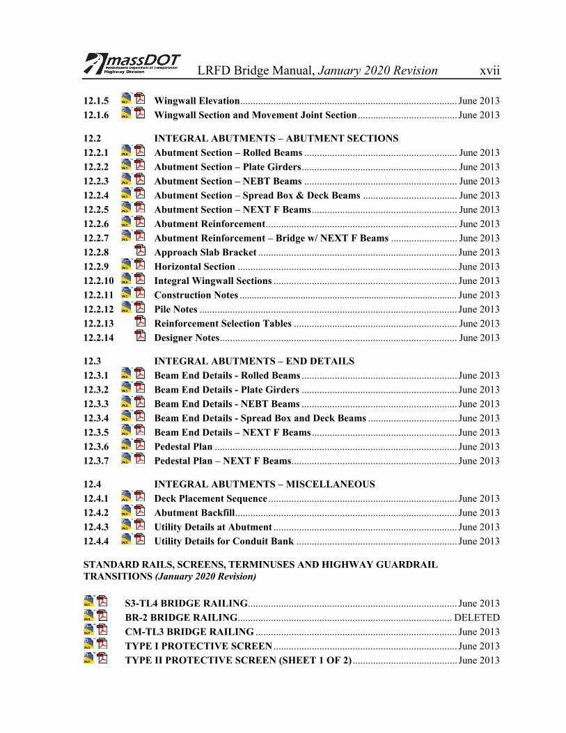
LRFD Bridge Manual, January 2020 Revision xvii 12.1.5 Wingwall Elevation ..................................................................................... June 2013 12.1.6 Wingwall Section and Movement Joint Section ....................................... June 2013 12.2 INTEGRAL ABUTMENTS – ABUTMENT SECTIONS 12.2.1 Abutment Section – Rolled Beams ............................................................ June 2013 12.2.2 Abutment Section – Plate Girders ............................................................. June 2013 12.2.3 Abutment Section – NEBT Beams ............................................................ June 2013 12.2.4 Abutment Section – Spread Box & Deck Beams ..................................... June 2013 12.2.5 Abutment Section – NEXT F Beams ......................................................... June 2013 12.2.6 Abutment Reinforcement ........................................................................... June 2013 12.2.7 Abutment Reinforcement – Bridge w/ NEXT F Beams .......................... June 2013 12.2.8 Approach Slab Bracket .............................................................................. June 2013 12.2.9 Horizontal Section ...................................................................................... June 2013 12.2.10 Integral Wingwall Sections ........................................................................ June 2013 12.2.11 Construction Notes ......................................................................................... June 2013 12.2.12 Pile Notes ..................................................................................................... June 2013 12.2.13 Reinforcement Selection Tables ................................................................ June 2013 12.2.14 Designer Notes ............................................................................................. June 2013 12.3 INTEGRAL ABUTMENTS – END DETAILS 12.3.1 Beam End Details - Rolled Beams ............................................................. June 2013 12.3.2 Beam End Details - Plate Girders ............................................................. June 2013 12.3.3 Beam End Details - NEBT Beams ............................................................. June 2013 12.3.4 Beam End Details - Spread Box and Deck Beams ................................... June 2013 12.3.5 Beam End Details – NEXT F Beams ......................................................... June 2013 12.3.6 Pedestal Plan ............................................................................................... June 2013 12.3.7 Pedestal Plan – NEXT F Beams................................................................. June 2013 12.4 INTEGRAL ABUTMENTS – MISCELLANEOUS 12.4.1 Deck Placement Sequence .......................................................................... June 2013 12.4.2 Abutment Backfill ....................................................................................... June 2013 12.4.3 Utility Details at Abutment ........................................................................ June 2013 12.4.4 Utility Details for Conduit Bank ............................................................... June 2013 STANDARD RAILS, SCREENS, TERMINUSES AND HIGHWAY GUARDRAIL TRANSITIONS (January 2020 Revision)
S3-TL4 BRIDGE RAILING .................................................................................. June 2013 BR-2 BRIDGE RAILING.................................................................................... DELETED CM-TL3 BRIDGE RAILING ............................................................................... June 2013 TYPE I PROTECTIVE SCREEN ........................................................................ June 2013 TYPE II PROTECTIVE SCREEN (SHEET 1 OF 2) ......................................... June 2013

LRFD Bridge Manual, January 2020 Revision xviii
TYPE II PROTECTIVE SCREEN (SHEET 2 OF 2) ........................................ June 2013 TYPE II ELECTRIFICATION BARRIER ........................................................ June 2013 HANDRAIL ........................................................................................................... June 2013 SNOW FENCE FOR CP-PL2 AND CF BARRIERS (SHEET 1 OF 2) ........... June 2013 SNOW FENCE FOR CP-PL2 AND CF BARRIERS (SHEET 2 OF 2) ........... June 2013 TOP OF PRECAST HIGHWAY GUARDRAIL TRANSITION
FOR S3-TL4 RAILING ........................................................................................ June 2013 TOP OF PRECAST HIGHWAY GUARDRAIL TRANSITION
FOR CT-TL2 BARRIER ...................................................................................... June 2013 TOP OF PRECAST HIGHWAY GUARDRAIL TRANSITION
FOR CP-PL2 BARRIER ....................................................................................... June 2013 TOP OF PRECAST HIGHWAY GUARDRAIL TRANSITION
FOR CF-PL2 BARRIER ....................................................................................... June 2013 TOP OF PRECAST HIGHWAY GUARDRAIL TRANSITION
FOR CF-PL3 BARRIER ....................................................................................... June 2013 HIGHWAY GUARDRAIL TRANSITION FOR BR-2 RAILING .................. DELETED HIGHWAY GUARDRAIL TRANSITION FOR CM-TL3 RAILING ............. June 2013 TERMINUS FOR BR-2 BRIDGE RAILING .................................................... DELETED TERMINUS FOR CM-TL3 BRIDGE RAILING ............................................... June 2013