LRFD ATTACHMENT 1 - Caltrans€¦ · LRFD ATTACHMENT 2 Preliminary Foundation Data Table for...
12
5-19 EARTH RETAINING SYSTEMS COMMUNICATION — ATTACHMENTS 1 MeMo to Designers 5-19 • July 2015 LRFD Summary of Earth Retaining Systems District ERS ID Begin Station End Station ERS Type Comments/Notes Design Height (ft) Min. Max. ATTACHMENT 1
Transcript of LRFD ATTACHMENT 1 - Caltrans€¦ · LRFD ATTACHMENT 2 Preliminary Foundation Data Table for...

5-19 Earth rEtaining SyStEmS CommuniCation — attaChmEntS 1
MeMo to Designers 5-19 • July 2015
LRFD
Sum
mar
y of
Ear
th R
etai
ning
Sys
tem
s
Dis
trict
ER
S ID
Beg
in S
tatio
nEn
d St
atio
nER
S Ty
peC
omm
ents
/Not
esD
esig
n H
eigh
t (ft)
Min
.M
ax.
ATTACHMENT 1

MeMo to Designers 5-19 • July 2015
2 5-19 Earth rEtaining SyStEmS CommuniCation — attaChmEntS
LRFD ATTACHMENT 2
Prel
imin
ary
Foun
datio
n D
ata
Tabl
e fo
r Sp
ecia
l Des
ign
ER
S
Dis
trict
ER
S ID
Beg
in S
tatio
nEn
d St
atio
n
Prel
imin
ary
Exte
rnal
Loa
d @
To
p of
the
Wal
l(K
ips)
Prop
osed
ER
S Ty
peC
omm
ents
/Not
es
Des
ign
Hei
ght (
ft)
Min
.M
ax.
1
1Ex
tern
al lo
ad d
ue to
sign
stru
ctur
e, li
ght p
ole,
soun
dwal
l, or
oth
er ty
pe o
f loa
d pl
aced
on
top
of th
e ER
S. U
se N
/A w
hen
none
will
be
appl
ied.

5-19 Earth rEtaining SyStEmS CommuniCation — attaChmEntS 3
MeMo to Designers 5-19 • July 2015
LRFD ATTACHMENT 2
Prel
imin
ary
Foun
datio
n D
ata
Tabl
e - M
odifi
ed S
tand
ard
Plan
on
Spre
ad F
ootin
g
Dis
trict
ER
S ID
Beg
in S
tatio
nEn
d St
atio
nSt
anda
rd P
lan,
Typ
eFi
nish
ed G
rade
Elev
atio
n (f
t)B
otto
m o
f Foo
ting
Elev
atio
n (f
t)C
omm
ents
/Not
esM
in. F
ootin
g Si
zeB
(ft)
L (f
t)

MeMo to Designers 5-19 • July 2015
4 5-19 Earth rEtaining SyStEmS CommuniCation — attaChmEntS
LRFD ATTACHMENT 2
Prel
imin
ary
Foun
datio
n D
ata
Tabl
e - M
odifi
ed S
tand
ard
Plan
on
Pile
s
Dis
trict
ER
S ID
Beg
in S
tatio
nEn
d St
atio
nSt
anda
rd P
lan,
Typ
ePi
le T
ype(
s) C
onsi
dere
dC
omm
ents
/Not
es

5-19 Earth rEtaining SyStEmS CommuniCation — attaChmEntS 5
MeMo to Designers 5-19 • July 2015
LRFD ATTACHMENT 3
Geo
tech
nica
l Des
ign
Dat
a Ta
ble
- Sha
llow
Fou
ndat
ion
Part
1 o
f 2
Dis
trict
ER
S ID
or B
ridge
No
Beg
in S
tatio
nEn
d St
atio
nB
otto
m o
f Foo
ting
Elev
atio
n (f
t)Fo
otin
g or
Bas
eW
idth
(ft)
Min
imum
Foo
ting
Embe
dmen
t Dep
th (f
t)To
tal P
erm
issi
ble
Settl
emen
t (in
.)Se
gmen
t (ft)
Des
ign
Hei
ght (
ft)

MeMo to Designers 5-19 • July 2015
6 5-19 Earth rEtaining SyStEmS CommuniCation — attaChmEntS
LRFD ATTACHMENT 3
Geo
tech
nica
l Des
ign
Dat
a Ta
ble
- Sha
llow
Fou
ndat
ion
Part
2 o
f 2
Dis
trict
ER
S ID
or B
ridge
No
Beg
in S
tatio
nEn
d St
atio
n
Stre
ngth
1A
Lim
it St
ate
Extre
me
I Lim
it St
ate
Fact
ored
Stre
ngth
1B
Lim
it St
ate
Extre
me
II L
imit
Stat
eFa
ctor
edSe
gmen
t (ft)
Effe
ctiv
eFo
unda
tion
Wid
th (f
t)
Gro
ssU
nifo
rmB
earin
gSt
ress
(psf
)
Effe
ctiv
eFo
unda
tion
Wid
th (f
t)
Gro
ssU
nifo
rmB
earin
gSt
ress
(psf
)
Effe
ctiv
eFo
unda
tion
Wid
th (f
t)
Gro
ssU
nifo
rmB
earin
gSt
ress
(psf
)
Effe
ctiv
eFo
unda
tion
Wid
th (f
t)
Gro
ssU
nifo
rmB
earin
gSt
ress
(psf
)

5-19 Earth rEtaining SyStEmS CommuniCation — attaChmEntS 7
MeMo to Designers 5-19 • July 2015
LRFD ATTACHMENT 3
Geo
tech
nica
l Des
ign
Dat
a Ta
ble
- Sta
ndar
d Pl
an O
n Pi
les
Dis
trict
ER
S ID
or
Brid
ge N
oB
egin
St
atio
nEn
d St
atio
nM
ax.
Segm
ent
Serv
ice-
I Lim
it St
ate
Stre
ngth
Lim
it St
ate
(Con
trolli
ng G
roup
)Ex
trem
e Ev
ent L
imit
Stat
e (C
ontro
lling
Gro
up)
Segm
ent (
ft)To
tal l
oad
(kip
s)Pe
rm. l
oad
(kip
s)C
ompr
essi
on(k
ips)
Tens
ion
(kip
s)C
ompr
essi
on(k
ips)
Tens
ion
(kip
s)
Per
Segm
ent1
Max
. Pe
r Pile
Per
Segm
ent1
1
Max
. Pe
r Pile
Per
Segm
ent1
Max
. Pe
r Pile
Per
Segm
ent1
Max
. Pe
r Pile
Per
Segm
ent1
A w
all s
egm
ent i
s def
ined
as a
por
tion
of a
wal
l bet
wee
n tw
o ex
pans
ion
join
ts, f
ootin
g st
ep o
r the
beg
inni
ng/e
nd o
f a w
all a
nd a
n ex
pans
ion
join
t. W
here
ther
e ar
e no
ex
pans
ion
join
ts, u
se th
e en
tire
wal
l len
gth.

MeMo to Designers 5-19 • July 2015
8 5-19 Earth rEtaining SyStEmS CommuniCation — attaChmEntS
LRFD
Shal
low
Fou
ndat
ion
Des
ign
Rec
omm
enda
tions
- Pa
rt 1
of 2
Dis
trict
ER
S ID
or
Brid
ge N
oB
egin
St
atio
nEn
d St
atio
n
Min
. Fo
otin
gEm
bedm
ent
Dep
th(f
t)
Foot
ing
or
Bas
eW
idth
(ft)
Bot
tom
of
Foot
ing
Elev
atio
n(f
t)
Des
ign
Hei
ght
(ft)
Serv
ice
Lim
it St
ate
Settl
emen
t Se
gmen
t (ft)
Tota
lPe
rmiss
ible
(in.)
Cal
cula
ted
at N
etB
earin
gPr
essu
re (i
n.)
Net
Be
arin
gSt
ress
(psf
)
Effe
ctiv
eFo
unda
tion
Wid
th (f
t)
ATTACHMENT 4

5-19 Earth rEtaining SyStEmS CommuniCation — attaChmEntS 9
MeMo to Designers 5-19 • July 2015
LRFD
Shal
low
Fou
ndat
ion
Des
ign
Rec
omm
enda
tions
- Pa
rt 2
of 2
Dis
trict
ER
S ID
or
Brid
ge N
oB
egin
St
atio
nEn
d St
atio
n
Stre
ngth
1A
Lim
it St
ate
Stre
ngth
1B
Lim
it St
ate
Extre
me
I Lim
it St
ate
Extre
me
II L
imit
Stat
e Se
gmen
t (ft)
Effe
ctiv
eFo
und.
Wid
th(f
t)
Fact
ored
Bea
ring
Res
ist.
(psf
)
Gro
ssU
nifo
rmB
earin
gSt
ress
(psf
)
Effe
ctiv
eFo
und.
Wid
th(f
t)
Fact
ored
Bea
ring
Res
ist.
(psf
)
Gro
ssU
nifo
rmB
earin
gSt
ress
(psf
)
Effe
ctiv
eFo
und.
Wid
th(f
t)
Fact
ored
Bea
ring
Res
ist.
φ qn
,“φ
= _
__(p
sf)”
Gro
ssU
nifo
rmB
earin
gSt
ress
(psf
)
Effe
ctiv
eFo
und.
Wid
th(f
t)
Fact
ored
Bea
ring
Res
ist.
φ q n
,φ
= 1.
0(p
sf)
Gro
ssU
nifo
rmB
earin
gSt
ress
(psf
)
ATTACHMENT 4

MeMo to Designers 5-19 • July 2015
10 5-19 Earth rEtaining SyStEmS CommuniCation — attaChmEntS
LRFD
Shal
low
Fou
ndat
ion
Dat
a Ta
ble
Dis
trict
ER
S ID
or B
ridge
No
Beg
in S
tatio
nEn
d St
atio
n
Serv
ice
Lim
it St
ate
Perm
issi
ble
Net
Con
tact
Stre
ss (k
sf)
Segm
ent (
ft)D
esig
n H
eigh
t (ft)
Stre
ngth
Gro
ssN
omin
al B
earin
gR
esis
tanc
e fo
r C
ontro
lling
Loa
d C
ase,
φ =
___
____
(ksf
)b
Extre
me
Even
t G
ross
Nom
inal
Bea
ring
Res
ista
nce
φ =
1.0
0 (k
sf)
b
ATTACHMENT 4

5-19 Earth rEtaining SyStEmS CommuniCation — attaChmEntS 11
MeMo to Designers 5-19 • July 2015
LRFD
Pile
Des
ign
Rec
omm
enda
tions
Dis
trict
ER
S ID
or
Brid
ge N
oB
egin
St
atio
nEn
d St
atio
n
Serv
ice-
I Lim
it St
ate
Load
per
Se
gmen
tSt
reng
th L
imit
Extre
me
Lim
it
Nom
inal
Res
ista
nce
(kip
s)
Segm
ent (
ft)
Pile
Ty
peTo
tal
(kip
s)
Cut
-off
Elev
.(f
t)Pe
rman
ent
(kip
s)
Tota
l Pe
rmis
sibl
eSu
ppor
tSe
ttlem
ent
(in.)
Tens
ion
(φ =
1.0
)C
omp.
(φ =
1.0
)Te
nsio
n(φ
= 0
.7)
Com
p.(φ
= 0
.7)
Nom
inal
Driv
ing
Resis
tanc
e(k
ips)
Des
ign
Tip
Elev
atio
ns(ft
)
Spec
ified
Tip
Elev
atio
ns(ft
)
ATTACHMENT 4
MeMo to Designers 5-19 • July 2015
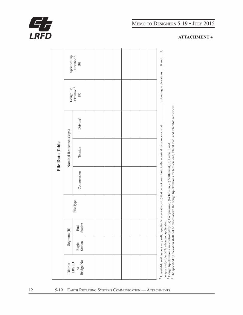
12 5-19 Earth rEtaining SyStEmS CommuniCation — attaChmEntS
LRFD
Pile
Dat
a Ta
ble
Dis
trict
ER
S ID
or
Brid
ge N
oB
egin
St
atio
nEn
d St
atio
n
Nom
inal
Res
ista
nce
(kip
s)
Segm
ent (
ft)
Pile
Typ
eC
ompr
essi
onTe
nsio
nD
rivin
g
Des
ign
Tip
Elev
atio
n(ft
)
Spec
ified
Tip
Elev
atio
n(ft
)
1
1
2
2
3
3
Uns
uita
ble
soil
laye
rs (v
ery
soft,
liqu
efia
ble,
scou
rabl
e, e
tc.)
that
do
not c
ontri
bute
to th
e no
min
al re
sist
ance
exi
st a
t ___
____
____
__ e
xten
ding
to e
leva
tions
___
ft an
d __
_ft,
resp
ectiv
ely.
Use
N/A
whe
n no
t app
licab
le.
Des
ign
tip e
leva
tions
are
con
trolle
d by
: (a)
Com
pres
sion
, (b)
Ten
sion
, (c)
Set
tlem
ent,
(d) L
ater
al L
oad.
The
spec
ified
tip
elev
atio
n sh
all n
ot b
e ra
ised
abo
ve th
e de
sign
tip
elev
atio
ns fo
r ten
sion
load
, lat
eral
load
, and
tole
rabl
e se
ttlem
ent.
ATTACHMENT 4