LP 13-20 DE - Atlas Copco Hydraulic Post Drivers ... · English 2 ˜"#$˙ % #˜˙" These operating...
14
LP 13-20 DE PAC ©Copyright 2005 ATLAS COPCO CONSTRUCTION TOOLS AB 2005-12 NACKA • SWEDEN No 3392 5019 01 a www.atlascopco.com Crowder Supply Co., Inc. • 8495 Roslyn St., Commerce City, CO 80022 • Toll Free: 888-883-5144 • www.CrowderSupply.com www.CrowderSupply.com • Toll Free: 888-883-5144
Transcript of LP 13-20 DE - Atlas Copco Hydraulic Post Drivers ... · English 2 ˜"#$˙ % #˜˙" These operating...

LP 13-20 DE PAC
����
������������������������������������
� ���� �����������
����������������������� ��!���� �
©Copyright 2005ATLAS COPCO CONSTRUCTION TOOLS AB 2005-12NACKA • SWEDEN No 3392 5019 01 awww.atlascopco.comCro
wde
r Sup
ply
Co.
, Inc
. • 8
495
Ros
lyn
St.,
Com
mer
ce C
ity, C
O 8
0022
• To
ll Fr
ee: 8
88-8
83-5
144
• ww
w.C
row
derS
uppl
y.co
mwww.CrowderSupply.com • Toll Free: 888-883-5144

1 English
��"#�"#��INTRODUCTION ..............................................................................................................2
SAFETY INSTRUCTIONS.................................................................................................2
Introduction to safety................................................................................................2
Safety symbols used.................................................................................................2
General safety rules..................................................................................................3
Protective equipment................................................................................................3
MARKINGS......................................................................................................................4
Identification.............................................................................................................4
CE.............................................................................................................................4
Safety signs on the Power Pack ...............................................................................4
GENERAL INFORMATION...............................................................................................4
Parts identification....................................................................................................5
OPERATING INSTRUCTIONS..........................................................................................6
Preparation before starting.......................................................................................6
Starting the engine (electric start).............................................................................7
Starting the engine (recoil start) ...............................................................................7
Stopping the engine..................................................................................................7
Hydraulic control and connectors.............................................................................8
Connecting/disconnecting hoses .............................................................................8
How to check the hydraulic system..........................................................................9
Service schedules...................................................................................................10
Scrapping and waste disposal................................................................................11
TROUBLE SHOOTING...................................................................................................11
TECHNICAL DATA ........................................................................................................12
Noise declaration statement...................................................................................13
Cro
wde
r Sup
ply
Co.
, Inc
. • 8
495
Ros
lyn
St.,
Com
mer
ce C
ity, C
O 8
0022
• To
ll Fr
ee: 8
88-8
83-5
144
• ww
w.C
row
derS
uppl
y.co
mwww.CrowderSupply.com • Toll Free: 888-883-5144
English 2
�"#$��%�#��"�These operating and safety instructions must be read before operating the machine. Instruc-tions for operation and basic maintenance are included. The purpose of this booklet is to givethe machine user an understanding of how to safely and efficiently use and maintain the ma-chine.
��&�#'��"�#$%�#��"��
������!�������� ������
To reduce the risk of serious injury to yourself or others, read these safety instructions beforeusing the Power Pack. Post these safety instructions at work locations, provide copies to em-ployees, and make sure that everyone reads the safety instructions before using the PowerPack. Comply with all safety regulations.
These instructions have been compiled from international safety standards and form part ofthe operating instructions. Signs and decals that are important for your safety and the care ofthe Power Pack are included with each power pack. Make sure that they are legible. Newdecals can be ordered using the spare parts list.
������� �()�* �! ���
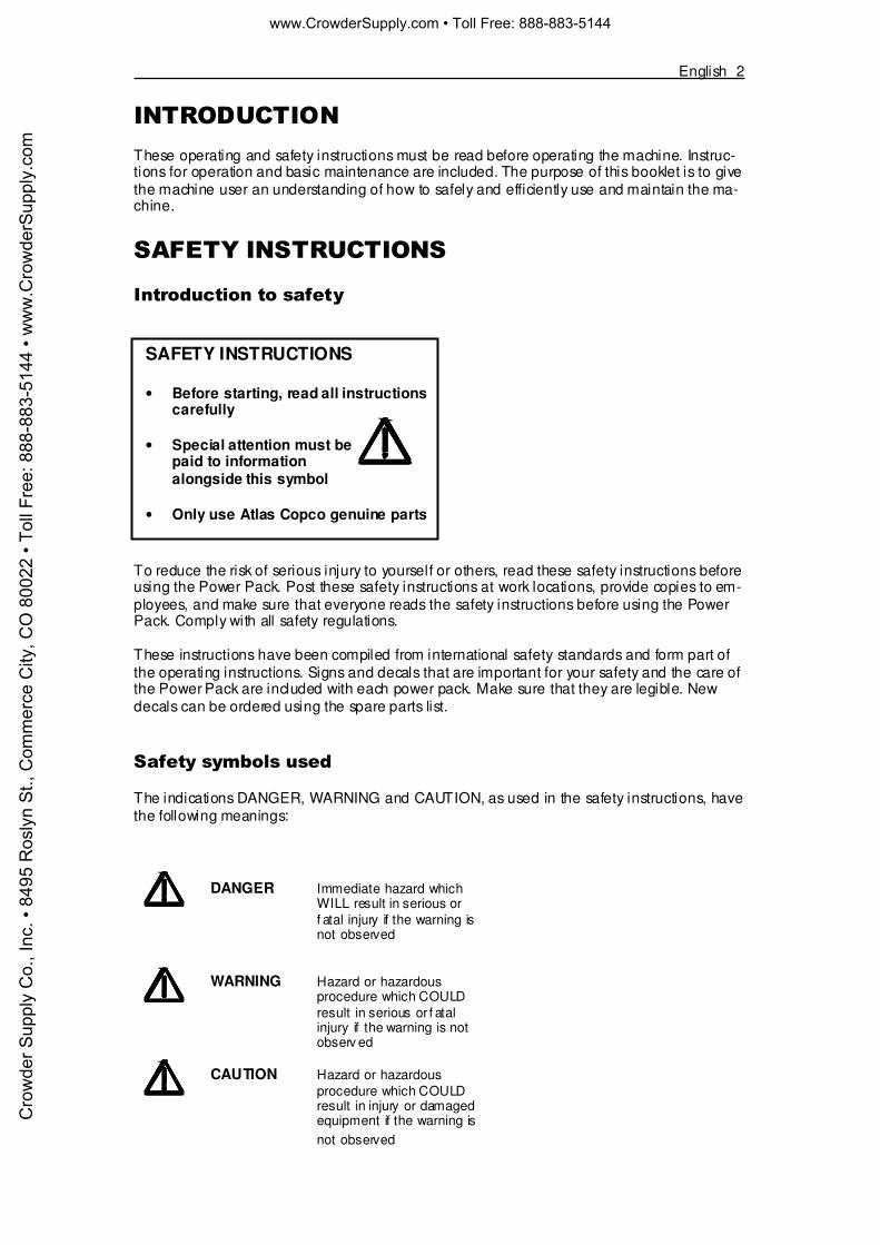
The indications DANGER, WARNING and CAUTION, as used in the safety instructions, havethe following meanings:
SAFETY INSTRUCTIONS
• Before starting, read all instructionscarefully
• Special attention must bepaid to informationalongside this symbol
• Only use Atlas Copco genuine parts
DANGER Immediate hazard whichWILL result in serious orf atal injury if the warning isnot observed
WARNING Hazard or hazardousprocedure which COULDresult in serious or f atalinjury if the warning is notobserv ed
CAUTION Hazard or hazardousprocedure which COULDresult in injury or damagedequipment if the warning isnot observed
Cro
wde
r Sup
ply
Co.
, Inc
. • 8
495
Ros
lyn
St.,
Com
mer
ce C
ity, C
O 8
0022
• To
ll Fr
ee: 8
88-8
83-5
144
• ww
w.C
row
derS
uppl
y.co
mwww.CrowderSupply.com • Toll Free: 888-883-5144
3 English
+�����*� �������!*� �
• The Power Pack and accessories must only be used for their purpose• Learn how the Power Pack is switched off in the event of an emergency• Only qualified and trained persons may operate or maintain the Power Pack• Keep the Power Pack in a safe place out of the reach of children, locked up• Pay attention and look at what you are doing• Use your common sense• Do not use the Power Pack when you are tired or under influence of drugs, alcohol or
anything else that may influence your vision, reaction or judgement• Never leave the Power Pack turned on• Avoid lifting a higher weight than that allowed according to your local environmental work-
ing regulations• Regular maintenance is prerequisite for machine safety. Carefully follow the operating
instructions. Replace damaged and worn components in good time. For major service tothe Power Pack, contact your nearest authorized workshop. When cleaning mechanicalparts with solvent, make sure to comply with current health and safety regulations andensure sufficient ventilation
• Breathing the Power Pack’s exhaust gases can harm and possibly kill you. Do not start orrun the Power Pack in enclosed areas, even if the doors and windows are open. Start andrun the Power Pack outdoors.
• Explosions and fire can be caused by sparks from the exhaust or the electrical system.Do not use the machine in closed areas with flammable material, vapour or dust.
�������,���-!��(����
Always use approved personal protective equipment. Operators and other staff in the prox-imity areas where work is in progress must as a minimum use the following approved protec-tive equipment:
• Hearing protection
When the Power Pack is used as a power source for breakers, cut-off saws and similar tools,use the following personal protective equipment:
• Protective helmet• Safety glass with side protection• Respiratory protection when appropriate• Protective gloves• Protective boots
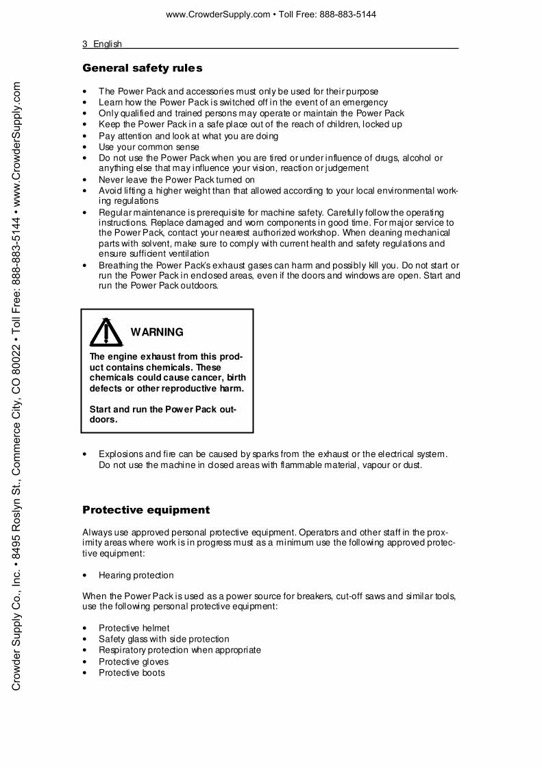
WARNING
The engine exhaust from this prod-uct contains chemicals. Thesechemicals could cause cancer, birthdefects or other reproductive harm.
Start and run the Power Pack out-doors.
Cro
wde
r Sup
ply
Co.
, Inc
. • 8
495
Ros
lyn
St.,
Com
mer
ce C
ity, C
O 8
0022
• To
ll Fr
ee: 8
88-8
83-5
144
• ww
w.C
row
derS
uppl
y.co
mwww.CrowderSupply.com • Toll Free: 888-883-5144
English 4
.�$/�"+��
��������������
���
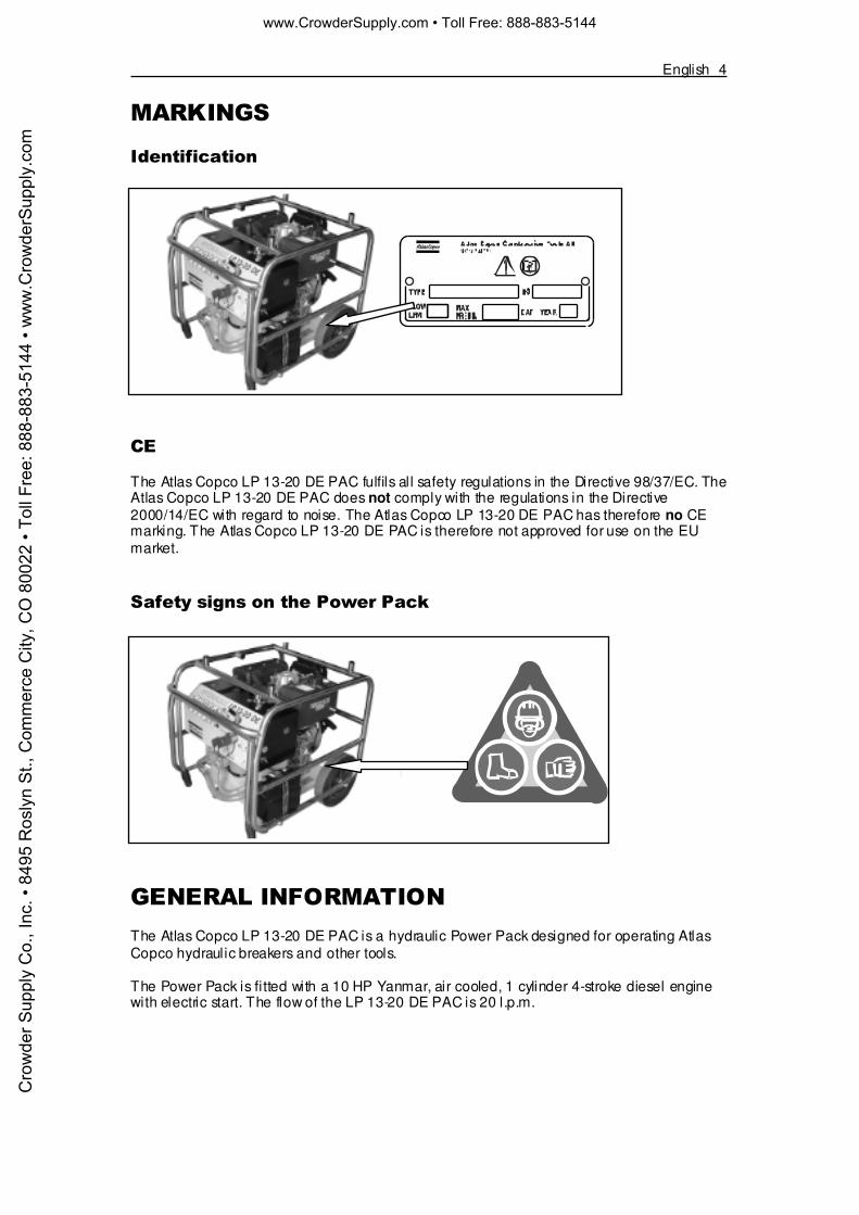
The Atlas Copco LP 13-20 DE PAC fulfils all safety regulations in the Directive 98/37/EC. TheAtlas Copco LP 13-20 DE PAC does not comply with the regulations in the Directive2000/14/EC with regard to noise. The Atlas Copco LP 13-20 DE PAC has therefore no CEmarking. The Atlas Copco LP 13-20 DE PAC is therefore not approved for use on the EUmarket.
������� ��� �����0�����������
+�"�$����"&�$.�#��"�The Atlas Copco LP 13-20 DE PAC is a hydraulic Power Pack designed for operating AtlasCopco hydraulic breakers and other tools.
The Power Pack is fitted with a 10 HP Yanmar, air cooled, 1 cylinder 4-stroke diesel enginewith electric start. The flow of the LP 13-20 DE PAC is 20 l.p.m.
Cro
wde
r Sup
ply
Co.
, Inc
. • 8
495
Ros
lyn
St.,
Com
mer
ce C
ity, C
O 8
0022
• To
ll Fr
ee: 8
88-8
83-5
144
• ww
w.C
row
derS
uppl
y.co
mwww.CrowderSupply.com • Toll Free: 888-883-5144
5 English
����� ���������������
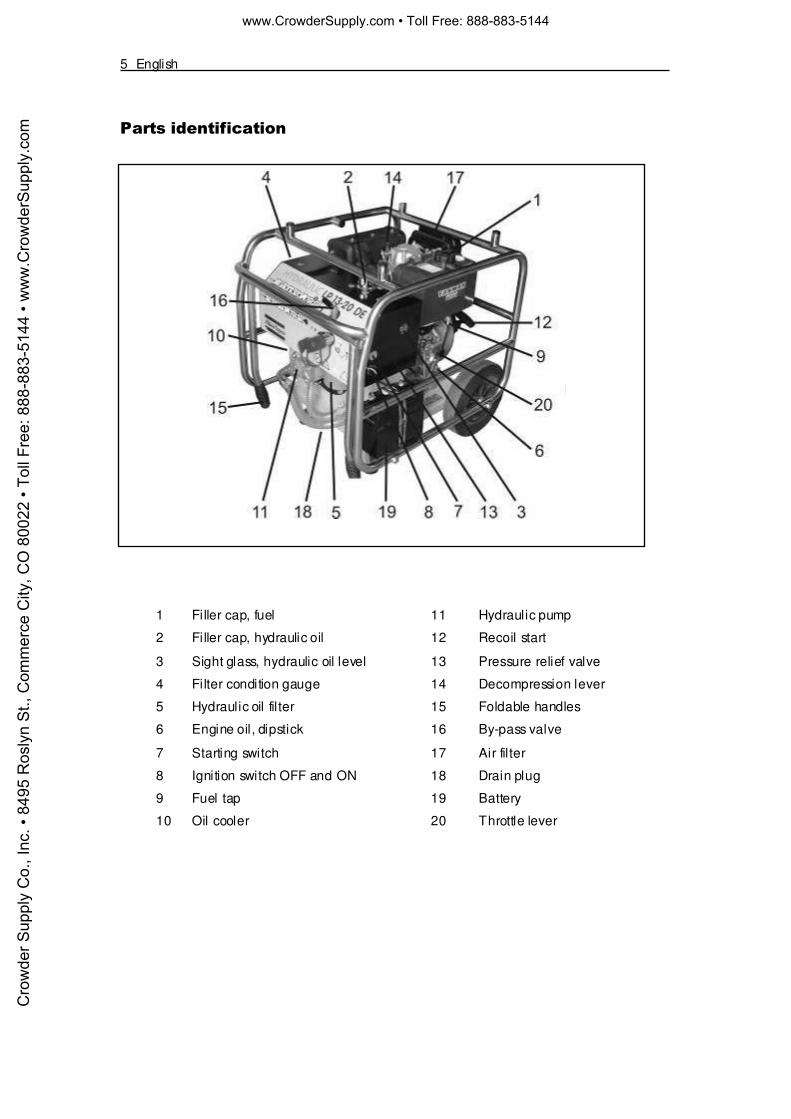
1 Filler cap, fuel 11 Hydraulic pump
2 Filler cap, hydraulic oil 12 Recoil start
3 Sight glass, hydraulic oil level 13 Pressure relief valve
4 Filter condition gauge 14 Decompression lever
5 Hydraulic oil fil ter 15 Foldable handles
6 Engine oil, dipstick 16 By-pass valve
7 Starting switch 17 Air filter
8 Ignition switch OFF and ON 18 Drain plug
9 Fuel tap 19 Battery
10 Oil cooler 20 Throttle lever
Cro
wde
r Sup
ply
Co.
, Inc
. • 8
495
Ros
lyn
St.,
Com
mer
ce C
ity, C
O 8
0022
• To
ll Fr
ee: 8
88-8
83-5
144
• ww
w.C
row
derS
uppl
y.co
mwww.CrowderSupply.com • Toll Free: 888-883-5144

English 6
���$�#�"+��"�#$%�#��"��
������������)������ ��������
The following checks should be made each time you return to the Power Pack after leaving itfor a period of time. All these checks concern the serviceability of the Power Pack. Someconcern your safety.
• Remove dirt and debris especially from around the linkage and hydraulic oil cooler• Clean all safety decals. Replace any that are missing or cannot be read• Inspect the Power Pack and hoses generally for signs of damaged and missing parts• Check for fluid and fuel leakages beneath the Power Pack• Check the security of the hinged frame• Make sure the fuel filler cap is tightly closed• Check the hydraulic oil level and add as necessary• Position the Power Pack in a safe position• Ensure that the hydraulic couplings are clean and fully serviceable• Ensure that any hydraulic tool you plan to use is compatible with the model of the Power
Pack you are using. See the section Flow rates• Check the engine oil level and add oil as necessary• Ensure that you have adequate fuel for the job. Top up as necessary, taking care not to
overfi ll
WARNING
• Diesel and its vapours are flammable and explosive. Fire or explosion cancause severe burns or death
• Keep naked flames away from the Power Pack
• Do not smoke while refuelling the Power Pack or working with the engine
• Do not refuel with the engine running. Turn off the engine and let the enginecool before refuelling
• Do not ov erfill the tank beyond the top of the red plug inside the fuel tank filter
Cro
wde
r Sup
ply
Co.
, Inc
. • 8
495
Ros
lyn
St.,
Com
mer
ce C
ity, C
O 8
0022
• To
ll Fr
ee: 8
88-8
83-5
144
• ww
w.C
row
derS
uppl
y.co
mwww.CrowderSupply.com • Toll Free: 888-883-5144

7 English
�����������0������������*����� �����
1. Set the hydraulic by-pass valve (A)in the OFF position
2. Set the fuel tap (B) in the O position(open)
3. Set the engine speed lever (C) in theSTART position
4. Turn the starting key (D) clockwiseto the START position
5. Remove your hand from the key, assoon as the engine starts
6. Let the engine warm up without loadfor about 3 minutes
����������0���������1�����*� �����
1. Set the hydraulic by-pass valve (A)in the OFF position
2. Set the fuel tap (B) in the O position(open)
3. Set the engine speed lever (C) in theSTART position
4. Pull out the recoil starting handle (E)to the point where you feel strongresistance and then return it to itsinitial position
5. Push down the decompression lever(F). It wil l return automatically whenthe recoil starter is pulled
6. Pull out the recoil starting handle (E)briskly with both hands
7. In cold weather, when your engine ishard to start, remove the rubber plug(G) of the rock arm cover and add 2cc of engine oil before starting
8. Let the engine warm up without loadfor about 3 minutes
����������0���������
1. Turn the hydraulic by-pass valve (C)to the OFF position
2. Move the throttle lever (H) to the lowspeed position and let the enginerun for about 3 minutes without load
3. Move the throttle lever (H) to theSTOP position
4. Turn the ignition key (D) counterclockwise to the OFF position
5. Set the fuel tap lever (B) to the Sposition
6. Slowly pull out the recoil startinghandle (E) until resistance is felt andleave the handle in this position.This prevents rust from formingwhile the engine is not in use
CAUTION
In order not to damage the starter,do not activ ate the starter for morethan 10 seconds. Wait for about 15seconds before the next try.
CAUTION
Do not allow the recoil startinghandle (E) to snap back against theengine. Return it gently to prev entdamage to the starter.
WARNING
Nev er use any cold-starting aidssuch as ether, gasoline, paint thin-ner or other v olatile liquid or gas.
Cro
wde
r Sup
ply
Co.
, Inc
. • 8
495
Ros
lyn
St.,
Com
mer
ce C
ity, C
O 8
0022
• To
ll Fr
ee: 8
88-8
83-5
144
• ww
w.C
row
derS
uppl
y.co
mwww.CrowderSupply.com • Toll Free: 888-883-5144
English 8
2����!*�������*������������ �
The by-pass valve (F) shall be in the OFFposition when starting and in the ONposition when using the tool.
Connectors (G) and (H) are used toconnect the Power Pack to the tool asfollows:
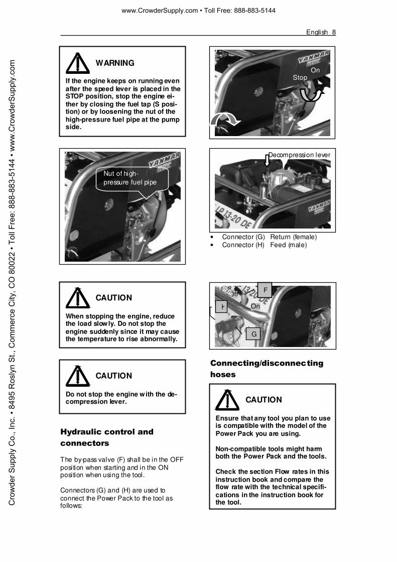
• Connector (G) Return (female)• Connector (H) Feed (male)
���������3�� ���������0� � �
WARNING
If the engine keeps on running evenafter the speed lever is placed in theSTOP position, stop the engine ei-ther by closing the fuel tap (S posi-tion) or by loosening the nut of thehigh-pressure fuel pipe at the pumpside.
CAUTION
When stopping the engine, reducethe load slowly. Do not stop theengine suddenly since it may causethe temperature to rise abnormally.
CAUTION
Do not stop the engine with the de-compression lever.
Decompression lever
CAUTION
Ensure that any tool you plan to useis compatible with the model of thePower Pack you are using.
Non-compatible tools might harmboth the Power Pack and the tools.
Check the section Flow rates in thisinstruction book and compare theflow rate with the technical specifi-cations in the instruction book forthe tool.
OnStop
Off
On
F
H
G
Nut of high-pressure fuel pipe
Cro
wde
r Sup
ply
Co.
, Inc
. • 8
495
Ros
lyn
St.,
Com
mer
ce C
ity, C
O 8
0022
• To
ll Fr
ee: 8
88-8
83-5
144
• ww
w.C
row
derS
uppl
y.co
mwww.CrowderSupply.com • Toll Free: 888-883-5144

9 English
Connecting hoses
1. Prepare the Power Packa) Turn the by-pass valve to the
OFF positionb) Stop the engine
2. Inspect the couplingsa) Ensure that the couplings are
clean and serviceable
3. Connect the hosesa) Attach the return lineb) Attach the feed linec) Rotate the collar on the female
coupling to secure the coupling
4. Check the hydraulic oil levela) Start the engine and run the
Power Pack to fil l up the hy-draulic circuit
b) Check the hydraulic oil level
Disconnecting hoses
1. Prepare the Power Packa) Turn the by-pass valve to the
OFF positionb) Stop the engine
2. Remove the hosesa) Rotate the collar on the female
couplingb) Release the return linec) Release the feed line
Note: The couplings are unlocked by mov-ing the collar back on the coupling
�����
�
�2������0���0��0����!*�� � ��(�
To set or check the oil flow and the pres-sure relief valve we recommend using theAtlas Copco test equipment or similar testequipment.
Part number 3371 8011 54
How to check
1. Stop the engine (see the sectionStopping the engine)
2. Connect the test equipment to thePower Pack. Male (B) to the returnconnection and female (A) to thefeed connection on the Power Pack.Make sure that the loading valve ofthe test equipment is fully open
3. Start the engine (see the sectionStarting the engine – electricstart)
4. Move the by-pass valve on thePower Pack to the ON position
5. Turn the loading valve, until thegauge shows approx. 70 bar (1000psi) and allow the Power Pack towarm up for 3-4 minutes
6. Slowly close the loading valve untilthe pressure gauge shows thenominal pressure according to thetechnical specifications
WARNING
Do not disconnect the hoses whenthe Power Pack is running or if thehydraulic oil is hot.
Hot hydraulic oil might cause seri-ous burns.
5-46 l/min. (1-12 gal/min.)
0-250 bar (0-3600 psi)
Cro
wde
r Sup
ply
Co.
, Inc
. • 8
495
Ros
lyn
St.,
Com
mer
ce C
ity, C
O 8
0022
• To
ll Fr
ee: 8
88-8
83-5
144
• ww
w.C
row
derS
uppl
y.co
mwww.CrowderSupply.com • Toll Free: 888-883-5144

English 10
7. Check that the flow is according tothe flow rate in the technical specifi-cations
Note: The inaccuracy of the reading on theflow meter is ±2 l.p.m. (±0.5gal/min). If the performance is not inaccordance with the technical speci-fications for the Power Pack, pleasesee the section TROUBLESHOOTING
���,��� 0��!*� �
A poorly maintained Power Pack is a haz-ard. Doing regular maintenance and lubri-cation jobs as listed in these schedules willhelp keep the Power Pack in a safe work-ing condition.
Apart from the daily jobs, the schedulesare based on the operation hours of thePower Pack. Keep a regular check ofhours in use. Do not use a Power Packthat is due for regular service. Rectify anydefects found during regular maintenancebefore clearing the Power Pack for use.
Daily
1. Clean the Power Pack in general2. Check fuel lines, tank, fuel cap and
fittings for cracks or leaks. Replace ifnecessary
3. Check for damages4. Check hydraulic fluid level5. Check engine oil level6. Check hydraulic couplings7. Check hydraulic hoses8. Check hydraulic oil fil ter
Note: Check tightness of nuts, bolts,screws and hose fittings after thefirst days of operation and thereafterin accordance with the maintenanceschedule
Note: The engine oil should be replacedafter the first 8 hours of operationand thereafter in accordance withthe maintenance schedule in theengine manufacturer’s operating andmaintenance instructions
WARNING
Maintenance must be done only bysuitably qualified and competentpersons.
Before doing any maintenance,make sure that the Power Pack issafe and correctly sited on levelground.
IMPORTANTWhen the filter gauge needle re-mains in the red sector (while theengine is running idle and the oil isservice warm), the filter must bereplaced. The old filter is removedby turning it clockwise (use a filterstrap wrench if necessary). Tiltingthe Power Pack rearwards willminimise oil spilling.
Before mounting the new filter, it isrecommended to grease the surfaceof the seal with oil in order to easecorrect tightening of the filter.
WARNING
Fine jets of hydraulic oil at highpressure can penetrate the skin. Donot use your fingers to check forhydraulic oil leaks. Do not put yourface close to suspected leaks. Holda piece of cardboard close to sus-pected leaks and then inspect thecardboard for signs of hydraulic oil.If hydraulic oil penetrates your skin,get medical help quickly.
Cro
wde
r Sup
ply
Co.
, Inc
. • 8
495
Ros
lyn
St.,
Com
mer
ce C
ity, C
O 8
0022
• To
ll Fr
ee: 8
88-8
83-5
144
• ww
w.C
row
derS
uppl
y.co
mwww.CrowderSupply.com • Toll Free: 888-883-5144

11 English
Ev ery 3 months
1. Do the daily jobs2. Check tightness of nuts, bolts,
screws and hose fittings3. Clean the air cleaner element (see
engine manufacturer’s handbook)
Ev ery 300 hours or ev ery year
1. Do the daily jobs and jobs every 3months
2. Change the hydraulic oil3. Change the hydraulic oil fil ter
��������������� ����� �� �*
Used and worn out parts must be treatedand disposed of in such a way that thegreatest possible part of them can be re-cycled and the influence on the environ-ment kept as low as possible
#$�%4����2��#�"+�
Problem Cause Solution
No fuel Top up tank
Fuel line blocked Clear line
Fuel tap in position 0 Move the fuel tap to position1
Engine turns over but doesnot start
Engine malfunction Refer to engine manual
By-pass valve in the ONposition
Turn valve to OFF
Engine malfunction Refer to engine manual
Engine does not turn overor is difficult to turn
Battery uncharged Start engine with recoil startor recharge battery
Damaged hoses Check and replace if needed
Leaking connections Check for tightness/leaks
Low hydraulic oil level
Defect hose couplings Replace couplings
Low pressure relief valvesetting
Adjust valve
High back pressure Check hose system forblockage
Poor tool performance
Worn hydraulic pump Replace pump
WARNING
Maintenance must be done only by suitably qualified and competent persons.
Cro
wde
r Sup
ply
Co.
, Inc
. • 8
495
Ros
lyn
St.,
Com
mer
ce C
ity, C
O 8
0022
• To
ll Fr
ee: 8
88-8
83-5
144
• ww
w.C
row
derS
uppl
y.co
mwww.CrowderSupply.com • Toll Free: 888-883-5144

English 12
Problem Cause Solution
Check for loose connectionson line to pump
Make sure that the filler capon the tank is not loose
Frothy or creamy colouredhydraulic oil
Air or water in oil
Check that oil level is at thetop of the sight glass
Poor siting of Power Packcausing warm air torecirculate
Resite Power Pack for freeair circulation
Blocked oil cooler Blow cooler clean. NEVERuse a wire brush
Defect fan Replace fan
Back pressure too high Check hose system
Tool runs hot
Tool defect Check and service tool
Power Pack stops suddenly Out of fuel Top up tank
#��2"�������#��Dimensions
Height (A) 705 mm (27.7”)Width (B) 600 mm (23.6”)Length (C) 745 mm (29.3”)Weight with oil 116 kg (256 lbs)
Engine type
Engine Yanmar, air cooled, 1cylinder 4-stroke dieselengine with electric start
Performance 10 HP (7.4 kW) at 3600 rpm
Fuel Diesel
Starter Electric start and recoil handstart
Hydraulic system
Circuit type Open centre
Pump type Gear pump, directly drivenfrom the engine crankshaftby means of a flexiblecoupling
Filtration 25μ filter in return line. Filterby-pass valve in valve block
Cooling Thermostatically controlledsystem air blast oil cooler
Cro
wde
r Sup
ply
Co.
, Inc
. • 8
495
Ros
lyn
St.,
Com
mer
ce C
ity, C
O 8
0022
• To
ll Fr
ee: 8
88-8
83-5
144
• ww
w.C
row
derS
uppl
y.co
mwww.CrowderSupply.com • Toll Free: 888-883-5144

13 English
Fluids, lubricants, capacity andspecification
Item Capacity Fluid/lubricant
Litres (gal,US)
Engine (oil) Refer to manufac turer’s operati ngand maintenance instructi ons.
Fuel tank 4.7 (1.24) Diesel, cetan valuemore than 45
Hydraulic fluid 7 (1.85) Mobil EAL 224or similar
Flow rates
The European Hydraulic Tool Manufactur-ers Association (E.H.T.M.A.) has catego-rised hydraulic power packs and tools interms of flow rate and working pressure.
Our LP 13-20 DE PAC is categorised bythe E.H.T.M.A. as below:
Flow rate, l.p.m. (gal,US) 20 (5)Nominal pressure, bar (psi) 120 (1800)Max. pressure, bar (psi) 140 (2000)E.H.T.M.A. category C
Note: Atlas Copco hydraulic powerpacks are clearly marked withE.H.T.M.A. categories. It is im-portant that any tool used with thePower Pack is of a compatiblecategory. If any doubt, consultyour Atlas Copco dealer.
Hose length
1 In normal ambient temperature, 0-40°C (32-104°F), the maximum hoselength should not exceed 25 m (82 ft)
2 Normally, 7 m of Twin hoses are to beused for the Power Pack.
Twin hose and other accessories areshown in the spare parts list.
WARNING
The setting of the pressure reliefvalve on the Power Pack can insome cases be higher than the pre-scribed max. pressure according tothe E.H.T.M.A. category.
A too high pressure relief valve set-ting can harm the tool.
Readjust the pressure relief v alv eon the Power Pack if the technicalspecifications of the tool prescribea lower pressure relief valve settingthan the standard setting of thePower Pack.
IMPORTANTThe torque of the engine is reducedwhen reducing the rpm. The PowerPack can therefore not in all casesdeliver the maximum pressure atlow rpm.
Cro
wde
r Sup
ply
Co.
, Inc
. • 8
495
Ros
lyn
St.,
Com
mer
ce C
ity, C
O 8
0022
• To
ll Fr
ee: 8
88-8
83-5
144
• ww
w.C
row
derS
uppl
y.co
mwww.CrowderSupply.com • Toll Free: 888-883-5144