Low-Voltage Switchgear and Controlgear type NGW R -...
24
ELEKTROBUDOWA SA 10/K/2009/EN Low-Voltage Switchgear and Controlgear type NGW R CATALOGUE
-
Upload
nguyenkiet -
Category
Documents
-
view
236 -
download
5
Transcript of Low-Voltage Switchgear and Controlgear type NGW R -...

EL
EK
TR
OB
UD
OW
AS
A10/K/2009/EN
Low-Voltage Switchgear and Controlgeartype NGW R
CATALOGUE
INTRODUCTION1. GENERAL CHARACTERISTICS 1
1.1. APPLICATION 11.2. FEATURES 11.3. OPERATION CONDITIONS 11.4. CONFORMITY TO STANDARDS 1
2. TECHNICAL DATA 23. SWITCHGEAR DESIGN 2
4The 6The distribution busbars compartment 6The auxiliary/common circuits compartment 7
3.1. Sections with an air circuit breaker 83.2. Sections with withdrawable and remowable 93.3. Sections with a digital control and supervision system 103.4. Reactive power compensation sections 103.5. Lighting switchgears 113.6. Sections with blocks of disconnecting switches 11
4. MAIN CIRCUITS 125. OPERATION CHARACTERISTIC 15
5.1. Degree of protection 155.2. Interlocks 155.3. Protection against electic shock 155.4. Equipment supplied together with the switchgear 155.5. Operation equipment 155.6. Nameplates and labels 16
6. MOUNTING 167. TRANSFORMER CHAMBER 178. BUSDUCT 189.
10. TRANSPORT 2111. ORDERING 21
Functional units compartmentbusbars compartment
The connections compartment 7
part
DESIGNING 209.1. Contents of the engineering design 209.2. Hints for designing 20
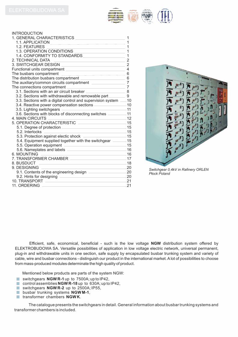
The catalogue presents the switchgears in detail. General information about busbar trunking systems and
transformer chambers is included.
Switchgear 0,4kV in Rafinery ORLENP³ock Poland
�
�
ELEKTROBUDOWA SA
Efficient, safe, economical, beneficial - such is the low voltage distribution system offered by
ELEKTROBUDOWA SA. Versatile possibilities of application in low voltage electric network, universal permanent,
plug-in and withdrawable units in one section, safe supply by encapsulated busbar trunking system and variety of
cable, wire and busbar connections - distinguish our product in the international market. A lot of possibilities to choose
from mass-produced modules determinate the high quality of product.
NGW
Mentioned below products are parts of the system NGW:
switchgears up to 7500A; up to IP42,control assemblies up to 630A; up to IP42,switchgears up to 2500A; IP55,busbar trunking systems ,transformer chambers .
NGW R-1NGW R-18
NGW R-2NGW M-1
NGW K
�
�
�
1
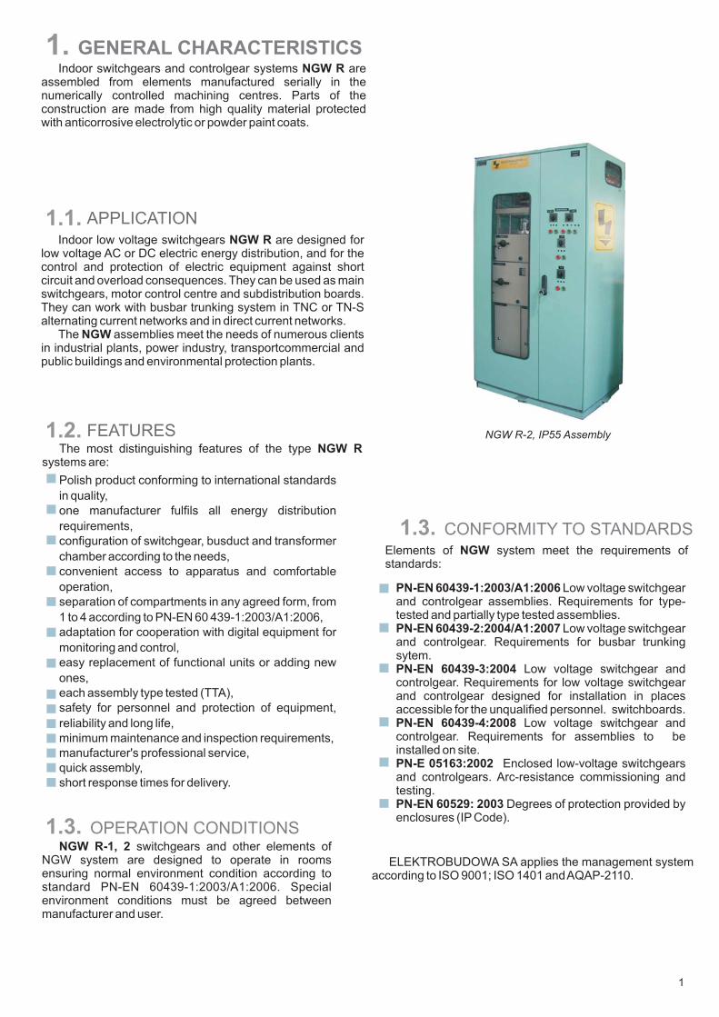
1. GENERAL CHARACTERISTICSIndoor switchgears and controlgear systems are
assembled from elements manufactured serially in thenumerically controlled machining centres. Parts of theconstruction are made from high quality material protectedwith anticorrosive electrolytic or powder paint coats.
NGW R
Indoor low voltage switchgears are designed forlow voltage AC or DC electric energy distribution, and for thecontrol and protection of electric equipment against shortcircuit and overload consequences. They can be used as mainswitchgears, motor control centre and subdistribution boards.They can work with busbar trunking system in TNC or TN-Salternating current networks and in direct current networks.
The assemblies meet the needs of numerous clientsin industrial plants, power industry, transportcommercial andpublic buildings and environmental protection plants.
NGW R
NGW
1.2. FEATURES
Polish product conforming to international standards
in quality,
one manufacturer fulfils all energy distribution
requirements,
configuration of switchgear, busduct and transformer
chamber according to the needs,
convenient access to apparatus and comfortable
operation,
separation of compartments in any agreed form, from
1 to 4 according to PN-EN 60 439-1:2003/A1:2006,
adaptation for cooperation with digital equipment for
monitoring and control,
easy replacement of functional units or adding new
ones,
each assembly type tested (TTA),
safety for personnel and protection of equipment,
reliability and long life,
minimum maintenance and inspection requirements,
manufacturer's professional service,
quick assembly,
short response times for delivery.
1.3.NGW R-1, 2 switchgears and other elements of
NGW system are designed to operate in roomsensuring normal environment condition according tostandard . Specialenvironment conditions must be agreed betweenmanufacturer and user.
PN-EN 60439-1:2003/A1:2006
NGW R-2, IP55 Assembly
OPERATION CONDITIONS
The most distinguishing features of the typesystems are:
NGW R
1.3.
PN-EN 60439-1:2003/A1:2006
PN-EN 60439-2:2004/A1:2007
Low voltage switchgearand controlgear assemblies. Requirements for type-tested and partially type tested assemblies.
Low voltage switchgearand controlgear. Requirements for busbar trunkingsytem.PN-EN 60439-3:2004
PN-EN 60439-4:2008
PN-E 05163:2002
PN-EN 60529: 2003
Low voltage switchgear andcontrolgear. Requirements for low voltage switchgearand controlgear designed for installation in placesaccessible for the unqualified personnel. switchboards.
Low voltage switchgear andcontrolgear. Requirements for assemblies to beinstalled on site.
Enclosed low-voltage switchgearsand controlgears. Arc-resistance commissioning andtesting.
Degrees of protection provided byenclosures (IP Code).
CONFORMITY TO STANDARDSElements of system meet the requirements ofstandards:
NGW
ELEKTROBUDOWA SA applies the management systemaccording to ISO 9001; ISO 1401 andAQAP-2110.
1.1. APPLICATION

ELEKTROBUDOWA SA
2. TECHNICAL DATA
2
Rated values
Rated voltage
Rated current In
insulation Ui
operation ue
continuous of horizontal busbars
continuous of supply cubicles
continuous of cubicle vertical buses
Short-circuit currents , , fault duration timeI I tcw pk cw
Rated frequency fr
Protection degree of enclosures according to IEC 529
Average mass of a section
Resistance to consequences of internal arcaccording to category B1*
3. SWITCHGEAR DESIGN
Mounting frame
Construction framework
Partitions between sections,mounting plates, connection elements
External enclosures
Construction parts of a section
protective coat Al-Zn
epoxy powder paint
protective coat Al-Zn
Corrosion-proof coating
epoxy powder paint
The basic moduleis a cuboid
125x50x50 mm
Construction parts of a switchgear section
Switchgear's construction allows for the installation of 3- or 4- poleapparatus. In segments there are separated compartments. Thecompartmented design provides the protection against contact withlive parts belonging to the adjacent functional unit and the reductionof spreading arc fault consequences outside the place it is initiated,and thus considerably increase the degree of safety.
Dimensions of a section are a multiple of a 125x50x50 mm cuboid.
Preferred dimensions of sectionsType of a section
with fixed parts up to IP42 or IP55
preferred sections up to IP42
Other dimensions subject to agreement
with a side connections compartment
with a rear connections compartment
with a side connections compartment
with a rear connections compartment
with a side connections compartment
with a rear connections compartment
version with an additional door
width w height h depth d
mm mm mm
with withdrawable/removable parts up to IP42
with withdrawable/removable parts IP55
850, 1000
700
950, 1100
800
650, 850, 1000
400, 600, 750, 1000
400, 600, 750, 850, 1000
2150
2150
2150
2150
550, 750, 1000
750, 900, 1000
700, 900, 1150
900, 1050, 1150
250, 400, 450, 550
600, 650, 750
550, 700, 750,900, 1000, 1150
V
NGW R-1 NGW R-2
up to 1000
up to 6300 up to 2500
up to 231 according to table page 6
50 ÷ 60
up to IP42 IP55
120 230
65 kA during 0,1s
up to 660
do 1000
NGW R-18
-
250
500
250
up to 630
125, 250
up to 1000
up to 660
up to 2500up to 7500
up to 1600 1600
V AC
V DC
A
AHz
kg
A
A

- main busbars
- auxiliary/common circuits
- distribution busbars of the segment
- connections
Options: from the bottom, from the left side, from the right side or from the back
- functional units
Functional compartments:
Optional configuration of sections
Double
incom
ing
feeder
A
A
A
A
AV
foundation
fram
e
50
2000
=16
xM
h=
2150
50
dw
Wall-mounted access from the front–
rear
connections
com
part
ment
Free-standing access from the front and back–
A
V
A
A
A
A
Form 1 Form 2a
Form 3a Form 3b Form 4a
Form 2b
Form 4b
Different forms of compartments separation according to PN-EN 60439-1:2003/A1:2006
In the switchgear design enables all methodsof internal division of a section by means of partitions orbarriers are possible. According to PN-EN 60439-1:2003/A1:2006 the inside of a section can be divided inone of the following ways:
NGW R
3
ELEKTROBUDOWA SA
4
�
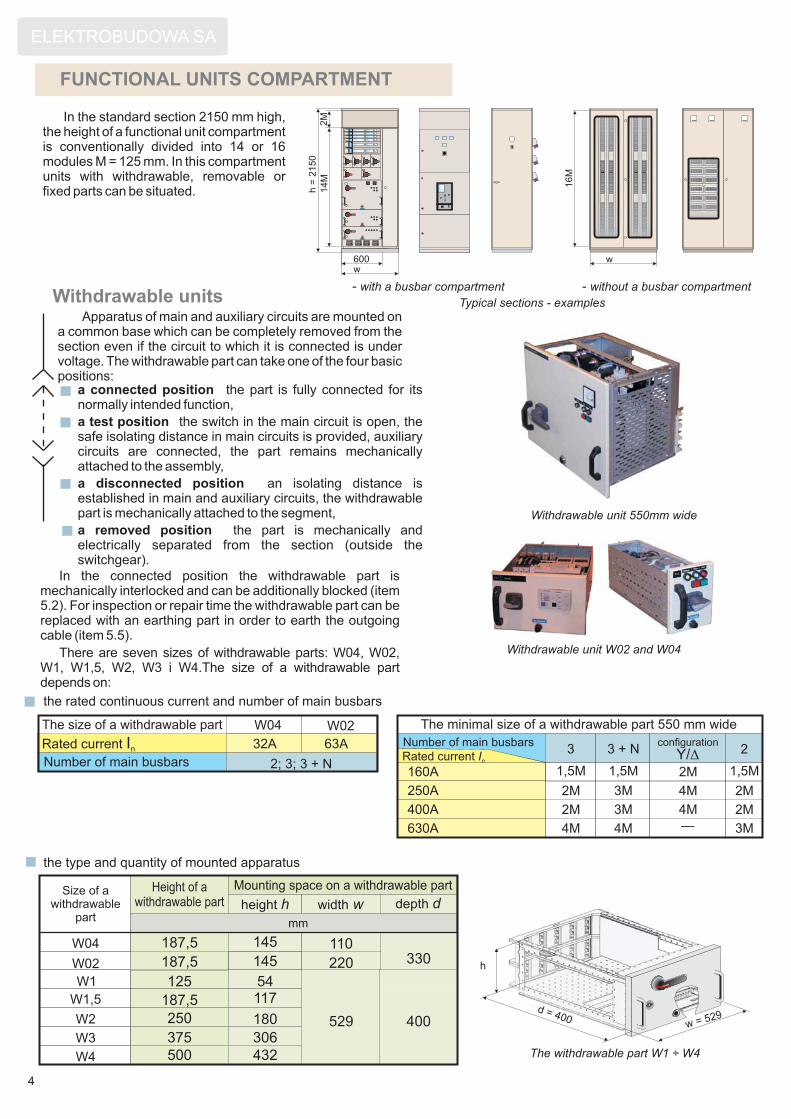
Apparatus of main and auxiliary circuits are mounted ona common base which can be completely removed from thesection even if the circuit to which it is connected is undervoltage. The withdrawable part can take one of the four basicpositions:
FUNCTIONAL UNITS COMPARTMENT
In the standard section 2150 mm high,the height of a functional unit compartmentis conventionally divided into 14 or 16modules M = 125 mm. In this compartmentunits with withdrawable, removable orfixed parts can be situated. 1
4M
2M
16M
w
Typical sections - examples
600
- with a busbar compartment - without a busbar compartment
h=
2150
w
A
A
A
A
A
A
V A
Withdrawable unit W02 and W04
Withdrawable units
a connected position
a test position
a disconnected position
a removed position
the part is fully connected for itsnormally intended function,
the switch in the main circuit is open, thesafe isolating distance in main circuits is provided, auxiliarycircuits are connected, the part remains mechanicallyattached to the assembly,
an isolating distance isestablished in main and auxiliary circuits, the withdrawablepart is mechanically attached to the segment,
the part is mechanically andelectrically separated from the section (outside theswitchgear).
In the connected position the withdrawable part ismechanically interlocked and can be additionally blocked (item5.2). For inspection or repair time the withdrawable part can bereplaced with an earthing part in order to earth the outgoingcable (item 5.5).
There are seven sizes of withdrawable parts: W04, W02,W1, W1,5, W2, W3 i W4.The size of a withdrawable partdepends on:
the rated continuous current and number of main busbars
the type and quantity of mounted apparatus
The withdrawable part W1 ÷ W4
W04
W02
The size of a withdrawable part
Rated current In
Number of main busbars
W04 W02
32A 63A
2; 3; 3 + N160A
250A
400A
630A
3 + N3
The minimal size of a withdrawable part 550 mm wide
2Number of main busbars
1,5M 1,5M 2M 1,5M
2M 3M 4M 2M
2M 3M 4M 2M
4M 4M 3M—
Rated current In
W1
W1,5
W2
W3
W4
Size of awithdrawable
partmm
Mounting space on a withdrawable part
height h width w depth dHeight of a
withdrawable part
187,5
187,5
187,5
125
250
375
500 432
306
180
117
529 400
145 330110145
54
220 h
d = 400w = 529
Withdrawable unit 550mm wide
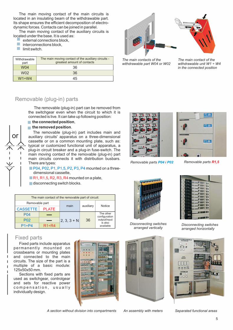
The main moving contact of the main circuits islocated in an insulating beam of the withdrawable part.Its shape ensures the efficient decomposition of electro-dynamic forces. Contacts can be joined in parallel.
The main moving contact of the auxiliary circuits islocated under the base. It is used as:
external connections block,interconnections block,limit switch.
Removable (plug-in) parts
Fixed partsFixed parts include apparatus
permanent ly mounted oncrossbeams or mounting platesand connected to the maincircuits. The size of the part is amultiple of a basic module:125x50x50 mm.
Sections with fixed parts areused as switchgear, controlgearand sets for reactive powerc o m p e n s a t i o n , u s u a l l yindividually design.
The main moving contact of the auxiliary circuits -greatest amount of contacts
36
45
W04
W1÷W4
Withdrawablepart
36W02
or
A section without division into compartments
The removable (plug-in) part can be removed fromthe switchgear even when the circuit to which it isconnected is live. It can take up following position:
,
.
The removable (plug-in) part includes main andauxiliary circuits' apparatus on a three-dimensionalcassette or on a common mounting plate, such as:
aplug-in circuit breaker and a plug-in fuse-switch. Themain moving contact of the removable partmain circuits connects it with distribution busbars.There are types:
, , , , , , mounted
disconnecting switch blocks.
the connected position
the removed position
typical or customized functional unit of apparatus,
(plug-in)
on a three-dimensional cassette,
, , , ,
P04 P02 P1 P1,5 P2 P3 P4
R1 R1,5 R2 R3 R4 mounted on a plate,
362, 3, 3 + N
The otherconfigurationoutput/input
is alsoavailable
The main contact of the removable part of circuit:
auxiliarymain NoticeRemovable part
CASSETTE
P04
P02
P1÷P4
PLATE
R1÷R4
––
The main contact of thewithdrawable unit W1 ÷ W4in the connected position
The main contacts of thewithdrawable part W04 or W02
Removable parts iP04 P02 Removable parts R1,5
Disconnecting switchesarranged vertically
Disconnecting switchesarranged horizontally
5
Separated functional areasAn assembly with meters

ELEKTROBUDOWA SA
The busbars compartment
The distribution busbars compartment
6
Vertical busbars are run in the rear of the section. Busbarscan have 2-, 3- or 4-pole arrangement, as:
applied at the reduction of the system, load symmetrically top-bottom
The main busbars run along the whole length of theswitchgear in the upper part of its sections. The arrangement andsize of copper conductors depend on technical parameters.
Busbars can be divided into sections to facilitate assembly ortransport. Sections of busbars are joined by special connectorswithout the need to make holes.
Inside the busbars compartment
Arrangement of busbars diagrams 1-7–
Holeless busbar joint
flat copper conductors consisting of one, two or three strips toconnect mechanically operated switches with busducts; flatbars from P30x10 to P100x10 are used,
channel bar conductors in isolating elements to connectwithdrawable and removable parts.
For optimal arrangement of distribution busbars it isrecommended to group the withdrawable, removable and fixedparts.
Flat conductors Channel shaped distribution busbars
Rated current
C400
C630
C1000
C1600
Size of channelshaped busbars
400
630
1000
1600
In Ipk Icw tcw
Fault duration time
sA kA kA
80
100
150
150
31,5
40
60
60
0,5
0,5
0,5
1,0
1250
1600
2000
2500
3200
4000
6300
400
750
In
A
5000
7500
Rated currents of busbars
kA
80
80
100
100
150
176
176
176
231
231
231
Ipk
31,5
105
105
Icw
kA
40
40
40
60
80
80
105
80
tcw
s
0,1
0,5
0,5
1,0
1,0
1,0
1,0
1,0
1,0
1,0
1,0
2x[2x(50x10)] *
2x[2x(100x10)]
3x[2x(80x10)]
2x[2x(80x10)]
Size of a copperconductor
3x[2x(100x10)]
2x(30x10)
2x(40x10)
2x(50x10)
2x(80x10)
2x(100x10)
mmxmm
30x10
30x5
Diagram
3 (5)
1 (6)
3
1
1
1
1
4*
2
2
7
7
L1 L2 L3 N L1 L2 L3 L1 L2 L3 N
L1 L2 L3 NL1 L2 L3 N
L1 L2 L3 N L1 L2 L3 N L1 L2 L3
7
Neutral bus N is half a phase bus size unless differentconstruction and design assumptions.
7
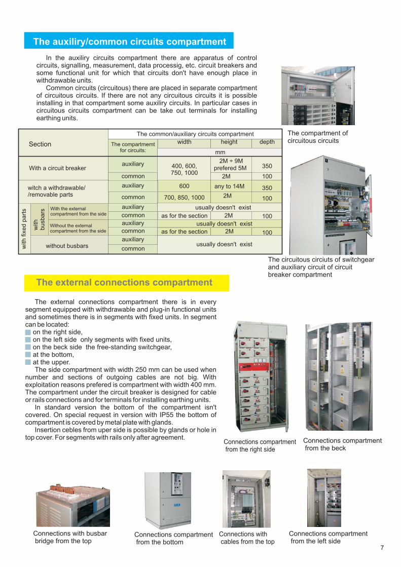
The compartmentauxiliry/common circuits
In the auxiliry circuits compartment there are apparatus of controlcircuits, signalling, measurement, data processig, etc. circuit breakers andsome functional unit for which that circuits don't have enough place inwithdrawable units.
Common circuits (circuitous) there are placed in separate compartmentof circuitous circuits. If there are not any circuitous circuits it is possibleinstalling in that compartment some auxiliry circuits. In particular cases incircuitous circuits compartment can be take out terminals for installingearthing units.
The external connections compartment
The external connections compartment there is in everysegment equipped with withdrawable and plug-in functional unitsand sometimes there is in segments with fixed units. In segmentcan be located:
on the right side,on the left side only segments with fixed units,on the beck side the free-standing switchgear,at the bottom,at the upper.The side compartment with width 250 mm can be used when
number and sections of outgoing cables are not big. Withexploitation reasons prefered is compartment with width 400 mm.The compartment under the circuit breaker is designed for cableor rails connections and for terminals for installing earthing units.
In standard version the bottom of the compartment isn'tcovered. On special request in version with IP55 the bottom ofcompartment is covered by metal plate with glands.
Insertion cebles from uper side is possible by glands or hole intop cover. For segments with rails only after agreement.
Connections compartmentfrom the right side
Connections withcables from the top
Connections compartmentfrom the left side
Connections with busbarbridge from the top
Connections compartmentfrom the beck
The circuitous circiuts of switchgearand auxiliary circuit of circuitbreaker compartment
The compartment ofcircuitous circuits
Connections compartmentfrom the bottom
100
with
busbars
without busbars
The compartmemtfor circuits:
The common/auxiliary circuits compartment
width height depth
mm
400, 600,750, 1000
2M ÷ 9M
prefered 5M
witch a withdrawable//removable parts
any to 14M
700, 850, 1000 2M
100
with
fixed
part
s
Usually doesn't exist
usually doesn't exist
With a circuit breaker
auxiliary
common
auxiliary
common
auxiliary
common
auxiliary
common
auxiliary
commonWith the externalcompartment from the side
Without the externalcompartment from the side
Section
350
2M
350
as for the section
as for the section
usually doesn't exist
usually doesn't exist
100
2M
2M
100
600
ELEKTROBUDOWA SA
Connections from the bottom
8
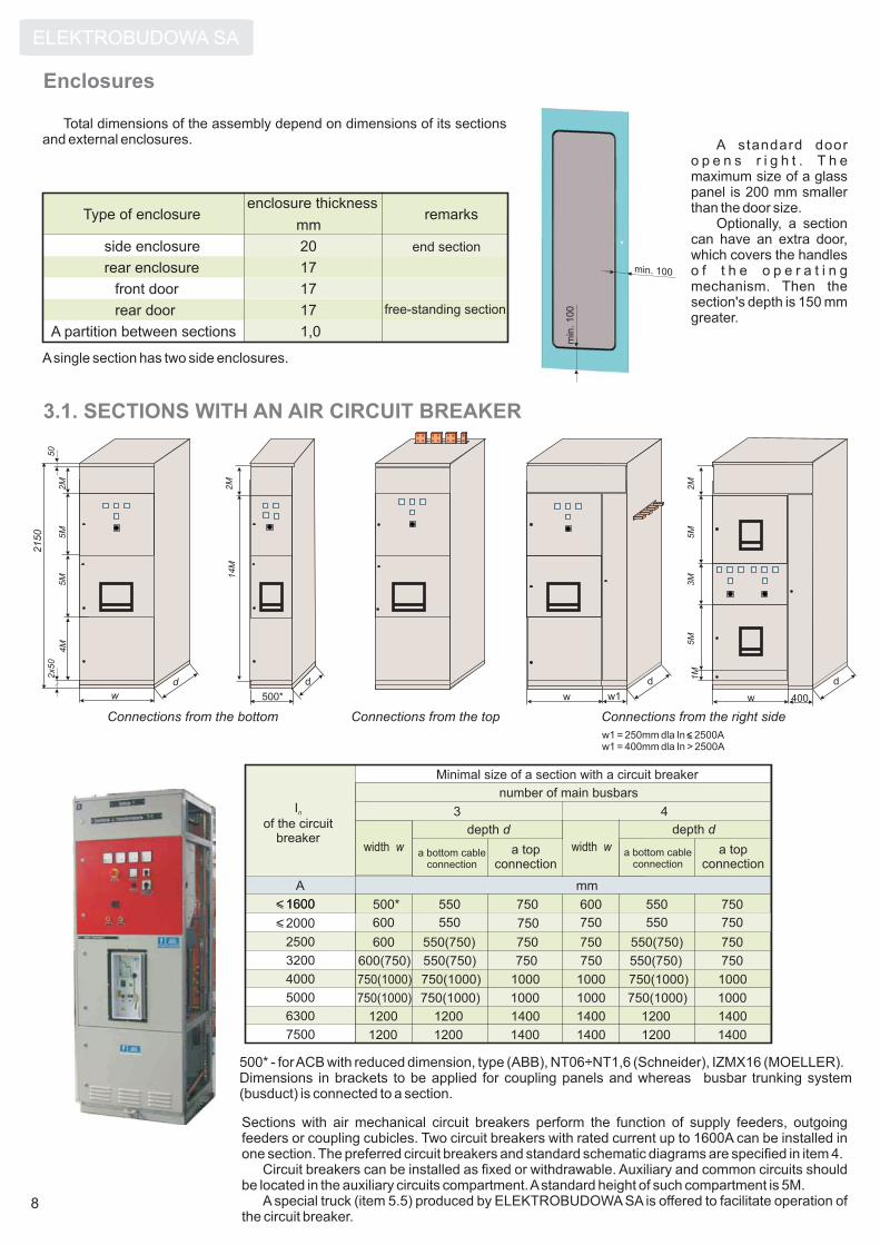
Enclosures
Total dimensions of the assembly depend on dimensions of its sectionsand external enclosures.
Type of enclosure
side enclosure
rear enclosure
front door
rear door
A partition between sections
enclosure thickness
mmremarks
end section
free-standing section
20
17
17
17
1,0
Asingle section has two side enclosures.
3.1. SECTIONS WITH AN AIR CIRCUIT BREAKER
A standard dooro p e n s r i g h t . T h emaximum size of a glasspanel is 200 mm smallerthan the door size.
Optionally, a sectioncan have an extra door,which covers the handleso f t h e o p e r a t i n gmechanism. Then thesection's depth is 150 mmgreater.
min. 100
min
.100
2150
2M
5M
5M
w
d
4M
w
d
w 400
d2M
5M
3M
5M
50
2x50
1M
2M
500*
d
w1
14M
Connections from the right sideConnections from the top
Sections with air mechanical circuit breakers perform the function of supply feeders, outgoingfeeders or coupling cubicles. Two circuit breakers with rated current up to 1600A can be installed inone section. The preferred circuit breakers and standard schematic diagrams are specified in item 4.
Circuit breakers can be installed as fixed or withdrawable. Auxiliary and common circuits shouldbe located in the auxiliary circuits compartment.Astandard height of such compartment is 5M.
A special truck (item 5.5) produced by ELEKTROBUDOWA SA is offered to facilitate operation ofthe circuit breaker.
500* - forACB with reduced dimension, type (ABB), NT06÷NT1,6 (Schneider), IZMX16 (MOELLER).Dimensions in brackets to be applied for coupling panels and whereas busbar trunking system(busduct) is connected to a section.
I
of the circuitbreaker
n
2500
3200
16001600
4000
5000
6300
7500
2 000
A
width w
Minimal size of a section with a circuit breaker
a bottom cableconnection
depth d
3
a topconnection
number of main busbars
width w
mm
a bottom cableconnection
depth d
4
a topconnection
750(1000)
750(1000)
1200
1200
600(750)
600
600
500*
550(750)
550(750)
550
550
750(1000)
750(1000)
1200
1200
750
750
750
750
1000
1000
1400
1400
750
750
750
600
1000
1000
1400
1400
550(750)
550(750)
550
550
750(1000)
750(1000)
1200
1200
1000
1000
1400
1400
750
750
750
750
w1 = 250mm dla In 2500Aw1 = 400mm dla In > 2500A
≤
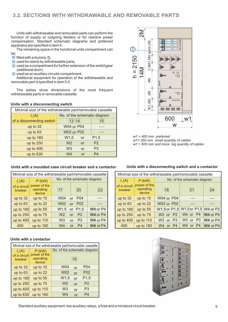
3.2. SECTIONS WITH WITHDRAWABLE AND REMOVABLE PARTS
Units with withdrawable and removable parts can perform thefunction of supply or outgoing feeders or for reactive powercompensation. Standard schematic diagrams and preferredapparatus are specified in item 4.
The remaining space in the functional units compartment canbe:
filled with a dummy ,used for stand-by withdrawable parts,used as a compartment for further extension of the switchgear(additional door),used as an auxiliary circuits compartment.Additional equipment for operation of the withdrawable and
removable part is specified in item 5.5.
The tables show dimensions of the most frequentwithdrawable parts or removable cassette.
Standard auxiliary equipment: two auxiliary relays, a fuse and a miniature circuit breaker.
Units with a disconnecting switch
In (A)
of a disconnecting switch
up to 32
up to 63
up to 160
up to 250
up to 400
up to 630
Minimal size of the withdrawable part/removable cassette
No. of the schematic diagram
W1,5
W2
W4
P1,5
P2
P4
W3 P3
w1 = 400 mm preferredw1= 250 mm small quantity of cablesw1 = 600 mm and more big quantity of cables
14
M2
M
A
A
A
A
600
h=
21
50
1,5
M1,5
M1,5
M2M
4M
w1
1M³¹
czni
e3,
5M
V A
w
9
Units with a moulded case circuit breaker and a contactor Units with a disconnecting switch and a contactor
In (A)
of a circuitbreaker
up to 32
up to 63
up to 160
up to 250
up to 400
400
Minimal size of the withdrawable part/removable cassette
No. of the schematic diagram
17
W04
W02
W1,5
W2
W4
20
W3
power of theoperating
device
up to 15
up to 22
up to 110
up to 160
P (kW)
23
W4
W4
W4
P04
P02
P1,5
P2
P4
P3
W4up to 55
up to 75
In (A)
of a circuitbreaker
up to 32
up to 63
up to 160
up to 250
up to 400
400
Minimal size of the withdrawable part/removable cassette
No. of the schematic diagram
power of theoperating
device
up to 15
up to 22
up to 110
up to 160
P (kW)
18 21 24
up to 55
up to 75
Units with a contactor
In (A)of a circuit
breaker
up to 32
up to 63
up to 160
up to 250
up to 400
Minimal size of the withdrawable part/removable cassetteNo. of the schematic diagram
power of theoperating
device
up to 15
up to 22
up to 110
up to 160
P (kW)
18
W04
W02
W1,5
W2
W4
W3
up to 55
up to 75
up to 630
13 14 15
P04
P02
P1,5
P2
P4
P3
P4
P4
P4
P4
W4
W4
W4
W4
P04
P02
W04
W02
or
or
or
or
or
or
or
or
or
or
or
or
or
or
or
or
or
or
or
or
or
or
P04
P02
P1,5
P2
P4
P3
or
or
or
or
or
or
W04
W02
W1,5
W2
W4
W3
P1,5
P4
P4
P3
or
or
or
or
W1,5
W4
W4
W3
W4
W4
W4
W4
P4
P4
P4
P2
W4
W4
W4
or
or
or
or
ELEKTROBUDOWA SA
Withdrawable part according tothe schematic diagram
Reactive power compensation section NGW R-1
10
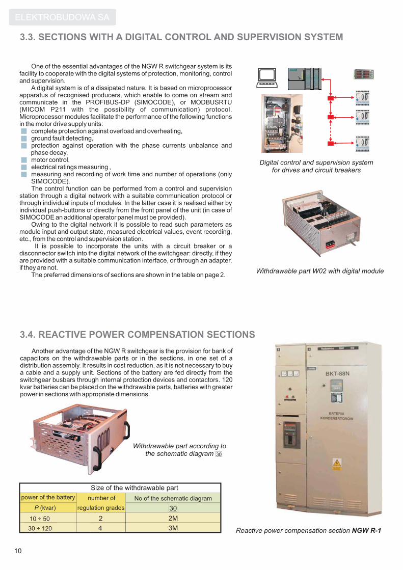
3.3. SECTIONS WITH A DIGITAL CONTROL AND SUPERVISION SYSTEM
One of the essential advantages of the NGW R switchgear system is itsfacility to cooperate with the digital systems of protection, monitoring, controland supervision.
A digital system is of a dissipated nature. It is based on microprocessorapparatus of recognised producers, which enable to come on stream andcommunicate in the PROFIBUS-DP (SIMOCODE), or MODBUSRTU(MICOM P211 with the possibility of communication) protocol.Microprocessor modules facilitate the performance of the following functionsin the motor drive supply units:
complete protection against overload and overheating,ground fault detecting,protection against operation with the phase currents unbalance andphase decay,motor control,electrical ratings measuring ,measuring and recording of work time and number of operations (onlySIMOCODE).The control function can be performed from a control and supervision
station through a digital network with a suitable communication protocol orthrough individual inputs of modules. In the latter case it is realised either byindividual push-buttons or directly from the front panel of the unit (in case ofSIMOCODE an additional operator panel must be provided).
Owing to the digital network it is possible to read such parameters asmodule input and output state, measured electrical values, event recording,etc., from the control and supervision station.
It is possible to incorporate the units with a circuit breaker or adisconnector switch into the digital network of the switchgear: directly, if theyare provided with a suitable communication interface, or through an adapter,if they are not.
The preferred dimensions of sections are shown in the table on page 2.
3.4. REACTIVE POWER COMPENSATION SECTIONS
Another advantage of the NGW R switchgear is the provision for bank ofcapacitors on the withdrawable parts or in the sections, in one set of adistribution assembly. It results in cost reduction, as it is not necessary to buya cable and a supply unit. Sections of the battery are fed directly from theswitchgear busbars through internal protection devices and contactors. 120kvar batteries can be placed on the withdrawable parts, batteries with greaterpower in sections with appropriate dimensions.
No of the schematic diagram
Size of the withdrawable part
power of the battery
regulation grades 30
2M
3M
2
430 ÷ 120
10 ÷ 50
number of
P (kvar)
Digital control and supervision systemfor drives and circuit breakers
Withdrawable part W02 with digital module
30

3.5. LIGHTING SWITCHGEARS
Lighting switchgears are designed for protection andcontrol of lighting and heating installations, ventilation or air-conditioning circuits and plug-in sockets in public buildings,production bays, shopping centres, etc. They are usuallysections 250 or 400mm deep.Available widths are specified inthe table on page 2. Doors can have a sight glass forinspecting the status of apparatus.
Sections with plug-in sockets on the side enclosure orbehind the door are used for feeding a construction site or abuilding under repair. Sections used for this purpose usuallyare 450 or 650 mm deep. Available widths are specified in thetable of the preferred dimensions on page 2. The heightdepends on the requirements and can be a multipleof M = 125mm.
11
3.6. SECTIONS WITH BLOCKS OF DISCONNECTING SWITCHES
Sections with blocks of disconnecting switches are applied inindustrial and power plants. They are particularly fit for municipal,district or plant transformer substations.
Dimensions of the switchgear with blocks of disconnectingswitches depend on current ratings and number of consumers.With the supply of maximum current 1600A the following
devices can be used:a moulded case circuit breaker,a disconnecting switch,a disconnector,direct busbar connection.
Rated continuous current of consumers is 630A.
I
I
n
n
d
w w w w
h2
h3
h1
50
2.1 2.2 2.3 2.4 2.5 3.13.2 3.3 3.4 3.5 4.4 4.54.1 4.2 4.3
Lighting switchgears
The preferred dimensions of sectionsare shown in the table on page 2
Switchger with blocks of fuse-switches
10M 0 1400
13M 3M 1775
16M 6M 2150
h3 h (mm)
any width
from 400 to 1500250, 450, 550
every 100mm
height depth width
d (mm) w (mm)
Sections with blocks of disconnecting switches vertical

ELEKTROBUDOWA SA
12
MAIN CIRCUITS4.
M M MM
M
MM
Fu
nctio
na
lu
nits
with
with
dra
wa
ble
pa
rts
MM MMM M M
Fu
nctio
na
lu
nits
with
fixe
dp
art
sF
un
ctio
na
lu
nits
witch
rem
ova
ble
pa
rts
up
to6
30
AF
un
ctio
na
lu
nits
with
with
dra
wa
ble
pa
rts
Fu
nctio
na
lu
nits
with
fixe
dp
art
sF
un
ctio
na
lu
nits
witch
rem
ova
ble
pa
rts
up
to6
30
A
BUSDUCT
BUSDUCT
13
M MM M M
M M M M
M M M M M
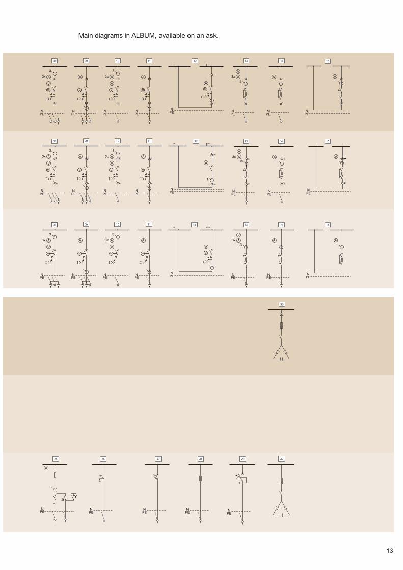
Main diagrams in ALBUM, available on an ask.
ELEKTROBUDOWA SA
14
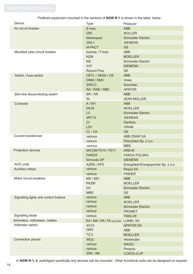
Prefered equipment mounted in the sections of is shown in the table belowNGW R-1
In switchgear practically any devices can be mounted . Other functional units can be designed on request.NGW R-1, 2
AREVA
FANOX POLSKA
SIEMENS
Energotest-Energopomiar Sp. z o.o.
Relpol SA
LUMEL SA
APATOR SA
Weidmuller
WAGO
Phoenix
..
various
MICOM P210 / P211
FANOX
Simcode DP
AZRS / APZ
EA / MA / PA / FA and other
4G10
WDU
Device Type Producer
Air circuit breaker
Moulded case circuit breaker
Switch / fuse-switch
Slim-line disconnecting switch
Current transformer
Protection devices
ACO units
Auxiliary relays
Motor circuit breakers
Signalling lights and control buttons
Signalling diode
Ammeters, voltmeters, meters
Connection pieces
Voltmeter switch
various
various
various
various
various
various
various
various
Contactor
various
FINDERvarious
various
MOELLERTZ-2
ABBOMV
CONTA-CLIPZRK / RK
GE
SIEMENS
Schneider Electric
ABB
Schneider Electric
ABB
ABB
Holec
Socomec
ABB
GE
Danfoss
ORAM
M-PACT
3WL1
Masterpact
E-max
NS
Isomax / T-max
OETL / OESA / OS
DMM / DMV
SIRCO
SR / XR
CL / CK
CI
LSV
MOELLERNZM
APATORRA / RAB / RBK
JEAN MÜLLERSL
MOLLERIZM
GERecord Plus
SIEMENS3VF
ABBA / EH
Schneider Electric
SIEMENS
LC
3RT10
MOELLERDILM
Polcontact Sp. z o.o.
ABB ZWAR SA
MBS
MOELLERPKZM
Schneider ElectricGV
GEMBS
ABBMS / MO
PROMET
MOELLER
Schneider Electric
TWELVE
ABB

15
5.1. DEGREE OF PROTECTION
In order to provide protection against contact with live parts andingress of solid foreign bodies and water, the switchgear is designed as:
5. OPERATIONAL CHARACTERISTICS
5.2. INTERLOCKS
5.3. PROTECTION AGAINST ELECTRIC SHOCK
5.4. EQUIPMENT SUPPLIED TOGETHER WITH THE SWITCHGEAR
5.5. OPERATION EQUIPMENT
A assembly is delivered together with :
bolts for connecting the cubicles
a set of busbar connecting pieces
0,4l of paint
keys for the doors.
NGW operation and maintenance manual and
Protection against direct contact is provided by barriers and enclosures.Protection against indirect is provided by using protective circuits. The construction together with a protective conductorprovides a suitable impedance of fault loop, so the fault protection devices can operate. Either neutral earthing orprotective earthing is applied, according to the user's needs.
According to PN-EN 60439-1:2003/A1:2006 the withdrawable parts can be inserted to the connected position orwithdrawn only when the main circuit is interrupted. Provision is made for additional interlocking with padlocks or key-operated locks.
The door of the functional unit/group can be provided with the interlock of opening in case of voltage presence. The doormay have a provision of sealing.
The switchgear can be designed as an open-type assembly with alower degree of protection; this must be indicated in the engineeringdesign.
Number of vent openings is designed by ELEKTROBUDOWA SA. Inthe IP55 design no vent openings can be foreseen.
Assembly / element Degree of protection
NGW R-1 up to IP42
NGW R-2 IP55
After opening the door
IP2XThe withdrawable part in the removed position
IP2X
earthing parts
a cubicle for earthing and replacement parts
a withdrawable part tester
extension cord for the removable part
a hand operated lifting truck.
Hand operated lifting truck
An extension cordfor removable parts
An earthing part
A cubicle for earthingand replacement parts
For the time of repair or replacement of the equipment beingfed the parts which supplies the consumer is replaced with aspecially marked earthing part which has the function of closingand earthing the outgoing contacts of the unit.
For the time of measurements and identification of damagethe inspected part of the switchgear is replaced with thewithdrawable part of a tester. The inspected part shall beinserted onto the guide rails of the tester upper shelf. Thecontrol circuits close automatically.
The extension cord is provided with a socket and a multi-pinplug connected by a multi-core conductor. Connection of thecontrol circuits of the inspected removable part with theswitchgear is provided through this connector.
A section IP55 NGW R-2
Withdrawable part tester

ELEKTROBUDOWA SA
16
�
�
�
�
6. MOUNTINGThe switchgears are usually arranged in one or two rows. It is
also possible to arrange the sections in a broken line. They canbe connected by an attachment box or a section of busduct.
Minimum distance between the switchgear and the wall of aroom is 100 mm. Recommended height of the switchgear roomis . For rooms which are not so high or whenbusducts are applied, please consult the manufacturer.
h + 500 mm
5.6. Nameplates and labels
x - number of a section, counting from the left side of theassembly
y - number of a functional unit of full width of the section,counting from the top of the switchgear
z - number of the functional unit counting from the left side ofthe section (parts 1/4M and 1/2M)
Elements of the NGW system are identified bynameplates according to PN-EN 60439-1:2003/A1:2006.Numbering and descriptions of functional units shall begiven in the engineering design. A number of the functionalunit is created in the following way:
A
A
A
A
A
A
V A
Examples:
1.4 Feeding from RS21.4 Feeding from RS2
1.5.3 Valve 3
1.8 Pump P21.8 Pump P2
2
Assemblies with various depths of the cubicles can beleveled to the deepest cubicle.
completion of construction and painting
completion of ventilation and water-sewage systems
completion of lighting installation
preparation of the mounting floor:
Preparation of the room for mounting the switchgear consists of:
mounting and levelling the foundation frames withaccuracy ± 2 on the whole lengthlevelling the part of the floor with holes,mounting the floor tiles on the fake floor,provision of the door opening width w + 100 mm andheight h + 100 mm,provision of key-lock or a padlock in the entrance door,provision of an entry in the wall if the switchgear is fedfrom the busduct situated in another room or from theoutside.
When the switchgear has been levelled the sections shall befixed:
on the foundation frame mounted in the floor or on the fakefloor made from steel shapes, with bolts or by welding in afew spots from inside, the welds shall be protected withanti-corrosive paint,
directly on the floor, using anchor sleeves, e.g. TKKM-8.
Holes in the floor
Main busbars connection of sections arranged at right angle
Foundation frames
L - foundation frame’s width
L1 - sum of widths cubicles with minimum depth d1
L2 - sum of widths cubicles with minimum depth d2
L3 - sum of widths cubicles with minimum depth d3
d
d-
10
0
w
w-100
d
d
w w
50 50
50
w1-70
w1
d-
10
0 50
50
w - cubicle’s widthw1 - connetions compartment’s
d - cubicle’s depthwidth
50
cubicle’s contour
maximal hole in the floor
a foundation frame
an anchor

17
7. TRANSFORMER CHAMBER
Technical data
Resistance to electric arcingconsequences, at current 65 kA in 0.1 s
NGW K
Degree of protection of enclosures
Power of transformer up to
Chamber dimensions
width
height
depth
Rated voltage
Mass of the chamber without transformer
mm
higher up to 7,2 kV, lower up to 690 V
The transformer chamber NGW K for dry-typetransformer of maximum rated higher voltage up to7,2 kV and power 3150 kVA has the followingfeatures:
A chamber located next to the switchgear isconnected with busbars. Cable or busductconnections are possible.
enclosure made of sheet painted with qualitypowder paint
easy dismantling of front enclosures facilitatesinspections and drawing out of the transformer
characteristic lifting of enclosures
enclosures have no connecting elementsoutside
inside: a section of low voltage busbar.
Convenient dismantling of front enclosure of the chamber 15/0,4kV assembly for industrial use
Transformer chamberNGW K
Switchgear NGW R
Switchgear 15kV
65kA / 0,1s
IP4X
up to 630 kVA up to 1250 kVA up to 3150 kVA
1800 2200 2600
2150 2150 2600
1100 1400 1600
550 kg 660 kg 760 kg

�
�
ELEKTROBUDOWA SA
8. BUSDUCT
the encapsulation, made of shaped and perforated aluminiumsheet, performs the function of an enclosure
conductors for any alternating or direct current systems aremanufactured
double-bar conductors are symmetrically laid
holeless connections of phase bars sections
straight sections, elbows and connection pieces are seriallymanufactured in numerically controlled machining centres
convenient location of inspection windows
the enclosure is painted with quality powder paint, standard colourRAL7032, other colours possible.
18
The enclosed busbar trunking system is applied as aprimary or stand-by supply circuit and the interconnection betweensections. Its self-supporting structure has the following features:
NGW M-1
Busbar supply of the switchgearfrom the transformer room
a
b
h
a
h
b
a
h1
h2
a
b
h
a
b
h
Straight horizontal (vertical) section
Connection box
Vertical elbow
Horizontal elbow
Clamp Wall passage enclosure
NGW M-1a b h
mm
1,25 ÷ 2,0
5,5
NGW M-1a b h
mm
1,25 ÷ 2,0
2,5 ÷ 3,15
up to 3000
350
550
850
200
250
250
4,0 ÷ 5,5
600
600
1000
250
300
300
600
600
800
NGW M-1a h1 h2
mm
1,25 ÷ 2,0
2,5 ÷ 3,15
4,0 ÷ 5,5
350
400
400
250
300
300
400
600
1000
NGW M-1a b h
mm
1,25 ÷ 2,0
2,5 ÷ 3,15
4,0 ÷ 5,5
400
600
1000
250
300
300
517
717
1117
2,5 ÷ 4,0

19
Application of the NGW M-1 enclosed busbur trunking system in the transformer and switchgear rooms
sekcjaII
sekcjaI
pole
zasil.pole
zasil.
blok
sprzê.blo
k
sprzê.
pole
zasil.pole
zasil.
9 10 6 7
1
11
7
6
11
9 1
5
9
3
1
8
4
12
2
4
3
1
8
3
8 3
7. wall passage enclosure8. level raiser9. support sling10. support gantry11. wall bracket12. supporting structure
1. straight horizontal section2. straight vertical section3. connection box4. vertical elbow5. horizontal elbow6. clamp
Technical data of busduct
Characteristic value
Rated voltage of insulation
Impulse withstand voltage 1.2/50 ms
Rated current:continuous
Rated current peak
Rated current withstand 1s
The Cu phase conductor
Mass of 1m busduct
Cross-sectional area of the busbar
Mean value:
impedance
reactance
1250 1600 2500 3150 4000
110 110 170 205 205
45 45 75 90 90
2xP30x10 2xP40x10 2xP80x10 2xP100x10 2x[2xP80x10]
35 40 75 90 135
400x250 400x250 600x300600x300 1000x300
0,110
0,100
0,110
0,100
0,091
0,090
0,091
0,090
0,052
0,051
1000
14,5
Unit
A
kA
kA
kg
mm2
kV
V
2000
150
60
2xP50x10
50
400x250
0,110
0,100
/1,25 /1,6 /2,5 /3,15 /4,0/2,0 /5,5
5500
231
105
2x[2xP100x10]
175
1000x300
0,091
0,090
NGW M-1
Degree of protection
resistance 0,017 0,017 0,009 0,009 0,0040,017 0,009
IP43up to
mÙ/m
mm
ELEKTROBUDOWA SA
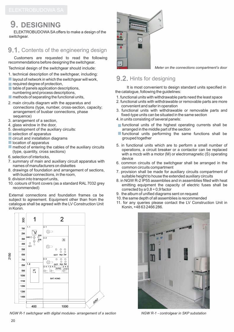
9. DESIGNINGELEKTROBUDOWA SA offers to make a design of the
switchgear.
functional units of the highest operating currents shall bearranged in the middle part of the sectionfunctional units performing the same functions shall begrouped together
9.1. Contents of the engineering design
9.2. Hints for designing
External connections and foundation frames ca besubject to agreement. Equipment other than from thecatalogue shall be agreed with the LV Construction Unitin Konin.
selection of apparatuscircuit and installation diagramslocation of apparatusmethod of entering the cables of the auxiliary circuits(type, quantity, cross sections)
Customers are requested to read the followingrecommendations before designing the switchgear.
Technical design of the switchgear should include:
layout of network in which the switchgear will work,required degree of protection,table of panels application descriptions,numbering and process descriptions,methods of separating the functional units,
1. technical description of the switchgear, including:
2. main circuits diagram with the apparatus andconnections (type, number, cross-section, capacity;arrangement of busbar connections, phasesequence)
3. arrangement of a section,4. glass window in the door,5. development of the auxiliary circuits:
6. selection of interlocks,7. summary of main and auxiliary circuit apparatus with
names of manufacturers on diskettes8. drawings of foundation and arrangement of sections,
with busbar connections, in the room,9. division into transport units,10. colours of front covers (as a standard RAL 7032 grey
recommended)
It is most convenient to design standard units specified inthe catalogue, following the guidelines:
1. functional units with withdrawable parts need the least space2. functional units with withdrawable or removable parts are more
convenient and safer in operation3. functional units with withdrawable or removable parts and
fixed-type units can be situated in the same section4. in units consisting of several panels:
5. in functional units which are to perform a small number ofoperations, a circuit breaker or a contactor can be replacedwith a mccb with a motor (M) or electromagnetic (S) operatingdevice
6. common circuits of the switchgear shall be arranged in thecommon circuits compartment
7. provision shall be made for auxiliary circuits compartment ofsuitable height to house the extended auxiliary circuits
8. in NGW R-2 IP55 assemblies and in assemblies filled with heatemitting equipment the capacity of electric fuses shall becorrected by a 0,8 ÷ 0,9 factor
9. the album of unified diagrams sent on request10. the same depth of all assemblies is recommended11. for any queries please contact the LV Construction Unit in
Konin, +48 63 2466 286.
NGW R-1 switchgear with digital modules- arrangement of a section
20
NGW R-1 - controlgear in SKP substation
Meter on the connections compartment’s door
11.
21
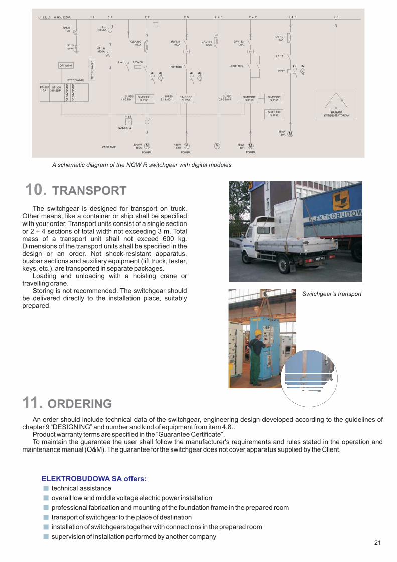
technical assistance
overall low and middle voltage electric power installation
professional fabrication and mounting of the foundation frame in the prepared room
transport of switchgear to the place of destination
installation of switchgears together with connections in the prepared room
supervision of installation performed by another company
Switchgear’s transport
10. TRANSPORT
The switchgear is designed for transport on truck.Other means, like a container or ship shall be specifiedwith your order. Transport units consist of a single sectionor 2 ÷ 4 sections of total width not exceeding 3 m. Totalmass of a transport unit shall not exceed 600 kg.Dimensions of the transport units shall be specified in thedesign or an order. Not shock-resistant apparatus,busbar sections and auxiliary equipment (lift truck, tester,keys, etc.). are transported in separate packages.
Loading and unloading with a hoisting crane ortravelling crane.
Storing is not recommended. The switchgear shouldbe delivered directly to the installation place, suitablyprepared.
ORDERING
ELEKTROBUDOWA SA offers:
An order should include technical data of the switchgear, engineering design developed according to the guidelines ofchapter 9 “DESIGNING” and number and kind of equipment from item 4.8..
Product warranty terms are specified in the “Guarantee Certificate”.To maintain the guarantee the user shall follow the manufacturer's requirements and rules stated in the operation and
maintenance manual (O&M). The guarantee for the switchgear does not cover apparatus supplied by the Client.
L1, L2, L3 0,4kV; 1250A 1.1 1. 2 2. 2 2. 3 2. 4. 1 2. 4. 2 2. 4. 3 2. 5
NH00125
ISN500/5A
NT 1.61600A
DEHNquard
M
QSA400400A
LSV400Ls4
3RV134100A
I >
3RV134100A
I >
3RV133100A
2x3RT1034
OS 4040A
LS 17
2x 3x1
2
B77T
2x 3x1
22x 3x
1
2
2x 3x1
2
2x 3x1
2
2x 3x1
2
DP/3WN6
ST
ER
OW
AN
IE
D1
16x24V
DC
D0
16x24V
DC
STEROWNIK
S7-300315-2DP
PS-3075A
SIMCODE3UF50
3UF5041-3.N0-1
3UF5021-3.N0-1
SIMCODE3UF50
3RT1046
3UF5021-3.N0-1
SIMCODE3UF50
SIMCODE3UF51
SIMCODE3UF52
BATERIAKONDENSATORÓW
1
1
PI 81
5A/4-20mA
M M M M
M
POMPA POMPA POMPA
ZASILANIE200kW
350A45kW
84A15kW
30A
15kW30A
A schematic diagram of the NGW R switchgear with digital modules

© Copyright by ELEKTROBUDOWA SAAll rights reserved. Subject to change without prior notice
® If not stated otherwise on the individual pages on this catalog, we reserve the right to include modifications, especiallyregarding dimensions and weights.Drawing are not binding.All product destignations used are trademarks product names of ELEKTROBUDOWA SA and other suppliers.
ELEKTROBUDOWA SA40-246 Katowice, ul. Porcelanowa 12tel. 48 32 2590 100 fax 48 32 205 27 60e-mail:http://www.elbudowa.com.pl
@elbudowa.com.plelbudowa
Power Distribution Division62-505 Konin, ul. Przemys³owa 156
tel. 48 63 2466 200 fax 48 63 2427 292e-mail: [email protected]
Edition Number Konin April 2009
We are in your disposal in any questions.
MARKETING OFFICE
Marketing Office - Overseas Market62-505 Konin, ul. Przemys³owa 156tel. +48 63 2466 371/348, fax +48 63 2466 304e-mail: [email protected]
Company Head Office