Low Velocity Impact Analysis With NASTRAN...Low Velocity Impact Analysis With NASTRAN Daniel A....
18
NASA Technical Memorandum 103169 _ Low Velocity Impact Analysis With NASTRAN ...... Daniel A. Trowbridge Analex Corporation NASA Lewis Research Center Fairview Park, Ohio and Joseph E. Grady and Robert A. Aiello Lewis Research Center Cleveland, Ohio Prepared for the 1990 NASTRAN _User "s_Cglioquium ..... cosponsored by COSMIC and the University of Georgia Portland, Oregon, April 23-27_ 1990 (NASA-T_-i-I03169) LOW V_LOCITY IMPACT ANALY_'IS_, WITH F_ASTRAN (NASA) 17 p CSCL II_ N91-14_26 Unc1 _s GJ/24 03204_0 https://ntrs.nasa.gov/search.jsp?R=19910005113 2020-04-12T19:04:15+00:00Z
Transcript of Low Velocity Impact Analysis With NASTRAN...Low Velocity Impact Analysis With NASTRAN Daniel A....

NASA Technical Memorandum 103169 _
Low Velocity Impact AnalysisWith NASTRAN ......
Daniel A. Trowbridge
Analex CorporationNASA Lewis Research Center
Fairview Park, Ohio
and
Joseph E. Grady and Robert A. AielloLewis Research Center
Cleveland, Ohio
Prepared for the
1990 NASTRAN _User "s_Cglioquium .....
cosponsored by COSMIC and the University of GeorgiaPortland, Oregon, April 23-27_ 1990
(NASA-T_-i-I03169) LOW V_LOCITY IMPACT
ANALY_'IS_, WITH F_ASTRAN (NASA) 17 p CSCL II_
N91-14_26
Unc1 _s
GJ/24 03204_0
https://ntrs.nasa.gov/search.jsp?R=19910005113 2020-04-12T19:04:15+00:00Z

Low Velocity Impact Analysis With NASTRAN
Daniel A. TrowbridgeAnalex Corporation
Fairview Park, Ohio 44126
Joseph E. Grady and Robert A. AieUo*NASA Lewis Research Center
Cleveland, Ohio 44135
ABSTRACT
A nonlinear elastic force--displacement relationship is used to calculate thetransient impact force and local deformation at the point of contact between impactor and
target. The nonlinear analysis and transfer function capabilities of NASTRAN are used todefine a finite element model that behaves globally linearly elastic, and locally nonlinearelastic to model the local contact behavior. Results are presented for two differentstructures: a uniform cylindrical rod impacted longitudinally; and an orthotropic plateimpacted transversely. Calculated impact force and transient structural response of thetargets are shown to compare well with results measured in experimental tests.
INTRODUCTION
Aerospace structures are subjected to impact loading from a variety of sources,
including dropped tools, runway debris, and munitions. In advanced composite materials,impact loading can cause significant internal structural damage, and a resulting loss ofstiffness and strength. Therefore, the development of an accurate means of calculatingstructural response due to impact loading is of critical importance in the analysis anddesign of advanced aerospace structures. In this paper, a computational technique isdeveloped to predict the dynamic response of a structure to a low velocity elastic impact.
Current work in this area has led to a variety of methods for calculating theresponse of a structure subject to impact loading. Lal [1] used 3 equivalent springs in seriesto model impact of a composite plate. The springs represented the indentation, andflexural and shear stiffnesses. The calculated displacement results compared well with histest measurements for low velocity impact. Schonberg, et aI. [2] developed a closed formsolution for the transverse impact of beams and plates by superimposing a static layersolution with elementary plate theory. His results showed that the impact force, maximumdisplacement and duration of contact were directly proportional to the target's mass,although the analysis could not be readily applied to inhomogeneous materials. Graves [3]wrote a FORTRAN computer program to model the impact of composite plates. Hepredicted damage contours in the target using a maximum shear stress criterion. Lee, et al.[4] developed a specialty finite element code and used a triangular pulse load to simulatethe impact force applied to a composite laminate. They showed that the higher modes ofthe target's frequency response are more pronounced near the point of contact with theimpactor. Sun [5] proposed a modified nonlinear elastic contact law for orthotropicmaterials that accounted for permanent indentation during unloading. The new contactlaw was used in a finite element program to calculate the dynamic response of compositebeams under transverse impact loading. Tan [6] extended this approach to laminatedplates. He used a nine-node isoparametric plate element to model the target, and his
Currently: Senior Structural Analyst, Analex Corporation, Fairview Park, Ohio.
1

calculated strain and impact force histories showed good agreement with test data. Sun [7]then included the effects of in-plane prestress on the plate. The calculated transient strain
response in the target .laminate showed good agreement with their experimentalmeasurements. A ggour [8] extended this work to include the effects of transverse shear androtary inertia. _train response from their analysis compared well with experimentalmeasurements obtained by Takeda [9-10]. Takamatsu, et aL [11] authored a threedimensional finite element code to predict impact damage in composite laminates. A
maximum stress failure criterion, as developed by Tsai [12], was used as a basis forprogressively altering the stiffness of the composite target. Humphreys [13] developed afinite element code that also included the effects of material damping, shear deformation,
and delamination. He used a stress-based failure criterion. Wu and Springer [14]developed a 3 dimensional transient finite element code that predicts delamination damagebased on a novel application of dimensional analysis. Calculated delamination contourswere shown to compare favorably with ultrasonic c-scans of impacted test specimens.
The most common approach to low velocity impact analysis is to develop aspecialty finite element program [4-14] that can account for the nonlinear elasticforce---displacement behavior in the contact region. Often a triangular of half---sinewaveform is assumed [1, 4] to represent the transient impact force history. In the workpresented here, a more straightforward method of impact modeling is presented, using thegeneral purpose structural analysis program NASTRAN. A nonlinear elastic contact law isused to model the local contact behavior, and the resulting impact force is calculated basedon the relative displacement between impactor and target.
BACKGROUND
Structural damage due to impact invariably initiates in the immediate vicinityof the impact. Therefore, it is important that the local stress field in the region of contactbe calculated accurately. The Hertzian contact law [15] is as an elasticity-basedforce-displacement relationship that describes contact between two elastic bodies. TheHertzian contact law is given by:
F = K a n (1)
where
and
F = elastic contact forceK - contact stiffness
n = exponent
a = relativedisplacement (indentation)between impactor and targetui-ut (i= impactor, t = target)
The exponent n was shown in reference[15]to have the value of 3]_. In thisapplication,force,displacement and indentation change with time.

During low velocity impact, structural damage to the target is negligible, andareas of the structure remote from the impact deform in a linear elastic manner. An
efficient finite element model, therefore, would combine a linear elastic model of the globalstructure with the prescribed non--linear elastic behavior at the point of contact with the
projectile. The nonlinear forc ey-displacement relationshi p in equation (1) is incorporatedinto a linear elastic finite element model (MSC/NASTRAN transient solution 27,
COSMIC/NASTRAN transient solution 9) by using a NASTRAN transfer functiondefinition and nonlinear analysis capability. In the following section, Hertz contact law is
discussed. The next section describes a straightforward method of incorporating thiscontact law into NASTRAN. Impact loading of two different structures is then analyzed.The first problem considered is a one--dimensional rod of uniform cross section impactedlongitudinally. The second is an orthotropic plate under transverse impact. Calculatedresults are compared with experimental test data for both cases.
CONTACT LAW
In reference [16], the derivation of the Hertzian force--displacement relationshipis given for two spherical isotropic elastic bodies of radius rl and r2 in contact. Theresulting equation is given by:
F = K _ 3/2 (2)
where
K = T r1+ r2 kl + k_ (3)
is the contact stiffness and
E °
- j= 1,2 (4)k_. 1 - v2.
J
where Ej and uj are the elastic modulus and Poisson ratio, respectively, and the subscripts
1 and 2 refer to each of the spheres. When a spherical impactor contacts a flat target,equation (3) simplifies to
ki+ kt ] (s)
where i and t represent the impactor and target, respectively, and ki and kt are given by:
ki - (6)1 -- vi
kt = Et 2 (7)1 -- vt
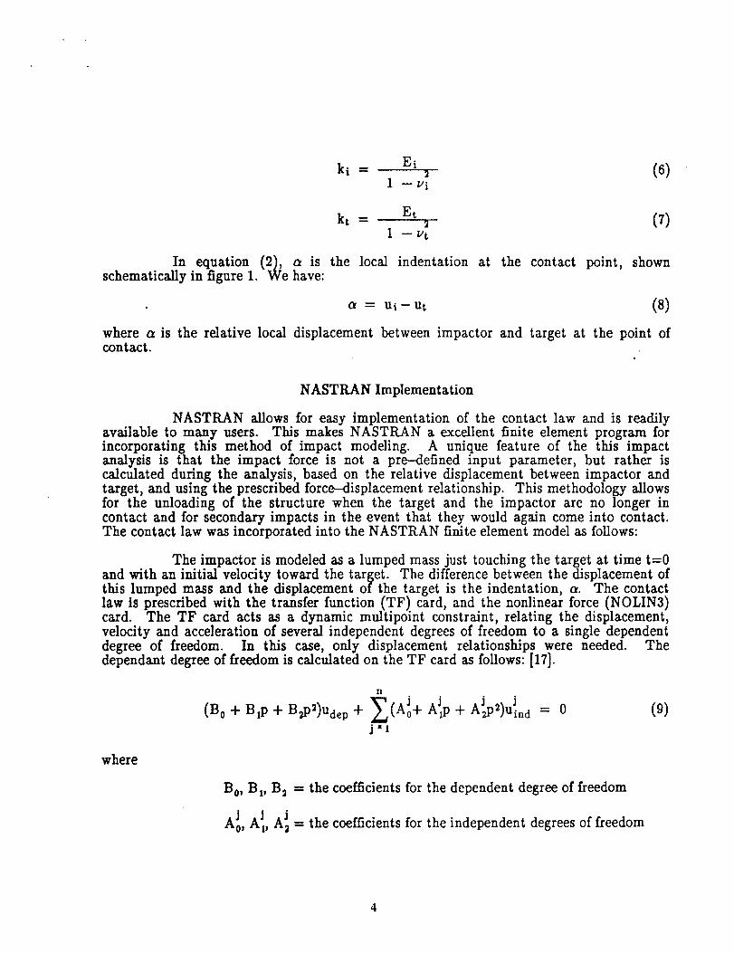
In equation (2), a is the local indentation at the contact point, shownschematically in figure 1. We have:
= ui- ut (8)
where a is the relative local displacement between impactor and target at the point ofcontact.
NASTKAN Implementation
NASTRAN allows for easy implementation of the contact law and is readilyavailable to many users. This makes NASTRAN a excellent finite element program forincorporating this method of impact modeling. A unique feature of the this impactanalysis is that the impact force is not a pre-defined input parameter, but rather iscalculated during the analysis, based on the relative displacement between impactor andtarget, and using the prescribed force--Aisplacement relationship. This methodology allowsfor the unloading of the structure when the target and the impactor are no longer incontact and for secondary impacts in the event that they would again come into contact.The contact law was incorporated into the NASTRAN finite element model as follows:
The impactor is modeled as a lumped mass just touching the target at time t=0and with an initial velocity toward the target. The difference between the displacement ofthis lumped mass and the displacement of the target is the indentation, a. The contactlaw is prescribed with the transfer function (TF) card, and the nonlinear force (NOLIN3)card. The TF card acts as a dynamic multipoint constraint, relating the displacement,velocity and acceleration of several independent degrees of freedom to a single dependentdegree of freedom. In this case, only displacement relationships were needed. Thedependant degree of freedom is calculated on the TF card as follows: [17].
(B 0 + Btp + B2p2)Ude p
II
• j J
j*l
= 0 (0)
where
B0, BI, B 2 = the coefficients for the dependent degree of freedom
J A Jr, JA0, A 2 = the coefficients for the independent degrees of freedom

Udep = the displacement of the dependent degree of freedom
JUin d -- the displacements of the independent degrees of freedom
n = the number of independent degrees of freedom
p = the differential operator, _-0 -andp2= o_,
For this analysis, the equation would appear:
that is
(l-O)Uextra point -_ [(--1.0)Uimpactor -}- (1.0)Utarget]=0 (10)
n -2
BpB2, AJpAJ2 - 0.0 (j--l,n)
B o = 1.0
l
A o =-1.0
The resultin_ equation defines the dependent degree of freedom as the indentation at each
time step of the transient analysis. The value of the indentation is assigned to anEPOINT. The EPOINT, or extra point, is a nonstructural variable that is used to store
the value of the indentation. The EPOINT is provided as input to the NOLIN3 card.
The NOLIN3 card is the means of applying the time-dependent nonlinear loadbased on the indentation. The NOLIN3 card has the form:
P(t) = [
S[x(t)] A, x(t) > 0
0 ,x(t)_<0
(11)
where
P(t) = the resultingnonlinear force
S = a scalefactor
x(t) = the displacement or velocityof a degree of freedom
A = an amplificationfactor
5

In modeling of the impact, we define x(t) to be the displacement of the EPOINT, S to bethe ,Hertzia_. s_tiffne_ss_, and A to be s/2, as given in equation (2). Rec_ that thedisplacement of the EPOINT is really the indentation as obtained from the TF card. Theresulting function then has the form:
FCt)-- I
x[ Ct)]3/2, > 0
0 , _(t) __ 0
(12)
Note that when a is less than or equal to zero(target and the impactor are no longer incontact), the contact force is also zero. Two NOLIN3 cards are used, one to apply theimpact force to the target and the other to apply the same force to the impactor in theopposite direction of its initial velocity. This methodology allows the impactor to slowwith increasing impact force and eventually to unload the target as the impactor begins totravel in the opposite direction, away from the target. Since the forcing function is not aninput parameter,, changing the properties of the target or the impactor does not requireassuming a new force-time relationship but only the recalculation of the contact stiffness,K, and changing the appropriate material property cards.
RESULTS
One Dimensional Rod
The first problem analyzed is the longitudinal impact of a steel ball on a longalundnum rod of constant cross section. Geometry and material properties of the impactorand target are given in figure 1. The problem was modeled using 144 1--dimensional rodelements with each grid point having a single longitudinal degree of freedom. Twoadditional degrees of freedom were used to model impactor and the extra point, resulting in
a total of 147 degrees_ of freedom. A single, lumped, mass with an initial, velocity was usedto represent the lmpactor. The Hertman force--displacement relatmnship in equation (1)was prescribed using the NASTRAN NOLIN3 card, as shown in the example input deck inthe appendix.
The impact force history obtained from the analysis compares well withexperimentally determined values [18 L as shown in figure 2. The calculated strain responseat the nddpoint of the target bar is compared with measured values in figure 3. The signreversal of the second pulse is caused by the reflected tensile stress wave generated by theincident compressive wave reaching the free end of the bar [19].
Some insight into the tinting and the location of the impact-induced structural
failure can be gained by tracking the distribution of energy in the impactor and the target,as shown in figure 4. The energy balance can be expressed as:
Utot = KEi+ SEi+KEt+ SEt (13)
where

Utot = total energyin system1 2
KEt - impactor kinetic energy = T mvi
2 KaS/_SEi = impactor strain energy = fF(a) da : --K-
KEt = target kinetic energyn
_ J+2Vi *l
j--
SEt = strain energy of targetn
2
-j=
(n : number of elements)
(n = number of elements)
(14)
(15)
(16)
(17)
The total energy in the system, Utot, isdivided between the kineticenergy andthe strain energy of the target and the impactor in a time-varying manner. Because
damping effectsaxe not considered, the total system energy is constant and equal to the
initialkineticenergy of the impactor. The strainenergy of the impactor is non-zero onlyduring the contact interval(0 < tc/L < 0.4,where t istime, L isthe length of the bar, and
c is the wave speed in the bar) and peaks when the contact forceisgreatest,approximately
halfway through the contact interval. The kineticenergy of the impactor decreases rapidly
as the impactor slows during contact with the target. Eventually, at tc/L __0.25, the
impactor velocity (and therefore its kinetic energy) decreases to zero and "the elastic
rebound begins. The kinetic energy of the impactor never returns to its initiallevel,
however, because approximately 80% of the energy has been transferredto the targetin the
form of strainenergy and kineticenergy. The strainand kineticenergiesin the target bothincrease rapidly during the contact with the impactor and remain constant after contact
has ended (tc/L > 0.4). Both strain and kinetic energies maintain equal and constant
values untilthe compressive stresswave generated by the impact reaches the far end of the
free-freebar (tc/L = 1.0). A tensilestresswave is generated when the compressive pulsereflectsfrom the stressfreeboundary [19]. The superposition of the incident and reflected
pulsesmomentarily leaves the bar stress-free,and the strainenergy decreases to zero. The
kinetic energy simultaneously increases,maintaining a conservation of total energy. Thereflectionprocess is repeated at tc/L = 2.0, when the reflected pulse returns to the
impacted end of the bar. Similar energy dissipation diagrams may prove useful in
analyzing dynamic failureof more complex structures. By tracking the distributionofenergy and assuming a strain energy based failurecriterion,it maybe possible to locate
areas of failurein the targetand predict the time of failureof these areas.
Composite Plate
The low velocity transverse impact of a composite plate made from Scotchply1003 prepreg [20] is now analyzed. The problem is depicted schematically in figure 5, andis described in detail in references [9, 10]. A modified Hertzian contact stiffness has beenproposed [5] for application to composite materials. Specifically, equation (7) is replacedby
kt =N E33 (18)

where E3s is the transverse (out--of-plane) modulus of the composite plate. Platemembrane and bending stiffness material properties were calculated using the COBSTRAN(Composite Blade Structural Analyzer) computer code [21] which calculates elastic moduliof composite materials from known constituent properties and laminate ply orientations.
A uniform square mesh of QUAD4 elements was used to model the 15.24 cmx
15.24 cm (6 in x 6 in) target plate. A mesh convergence study was performed to establishthe degree of mesh refinement necessary to arrive at a numerically converged solution.Three different meshes were considered, 25 ,, 25, 49 x 49, and 61 _ 61 elements. Of these,the latter two produced essentially the same strain response for a given impact velocity andwere therefore considered to be converged solutions. The results presented here were
therefore calculated using the 49 x 49 element model. Five degrees of freedom (ux, Uy, uz,0x and 0y)were used at each nodal point, giving the model a total of 11510 degrees offreedom. The problem was solved on a Cray XMP in 52 CPU minutes.
The impactor used in the tests [9, 10] was a uniform 2.54 cm (1 in) long,blunt--ended steel rod of radius 0.048 cm (s]le in). In the analysis, a contact radius of0.047625 cm (3/is in) was assumed in the Hertz_an contact stiffness calculations. Thecalculated impact force history is shown in figure 6. Although no direct measurement of
the impact force was obtained experimentally, the contact time was measured [8] and foundto be 204 microseconds. This is in good agreement with the calculated result. Figure 6also shows that a secondary impact occurs during the latter half of the contact interval (t
175 psec), probably due to the vibration of the target plate during contact with thelmpactor.
The resulting displacement response of the plate is shown in figure 7, where ithas been assumed that no damage occurs in the target during contact with the impactor.This assumption is valid based on the available test data. Ultrasonic C---scans of the
specimens after impact indicate that this level of impactor kinetic energy (10 Joules) isvery near the threshold energy level required to cause damage [10] in specimens of thislayup. As a result, very little damage occurs at this impact velocity. The anisotropicbending stiffness of the target is evident from the elliptical displacement contours, as theflexural disturbance travels faster in the stiffer direction, as shown in figure 7.
The strain response at gage A is compared to the calculated response in figure 8.The two curves are similar in amplitude and duration but the calculated strain appears tolagthe measured values by approximately 25 microseconds. This may be due to thedifficulty in establishing experimentally the precise time at which contact occurs based on
strain gage readings taken at some distance from the point of contact. The comparisonshown in figure 9 for gage B likewise shows a time shift of approximately 25 microsecondsbetween the measured and the calculated response. The amplitude and duration of thecalculated strain response correlate quite well with the measured signal.

SUMMARY
A simple means of modeling low velocity, non--damaging impact usingNASTRAN was demonstrated. A nonlinear elasticcontact model was included in the finite
element analysis using NASTRAN transfer function definitionsand nonlinear analysis
capabilities.The same contact law was used to define the force---indentationrelationshipfor two differentimpactor/target combinations. Results in both cases showed that the
impact force and resulting transient structural response of the target compared well withexperimentally measured values. Future work will include the effects of damage and theresulting progressive loss of structural stiffness that occurs during higher velocity impactevents..
ACKNOWLEDGEMENT
The support of the Naval Weapons Center at China Lake, CA. is gratefully
acknowledged. Mr. Andrew Victor was the technicalmonitor.

[1]
[2]
[3]
[4]
Is]
[6]
[7]
[8]
[9]
[lO]
[11]
[12]
REFERENCES
Lal, K. M., "Low Velocity Transverse Impact Behavior of 8-ply,Graphite EpoxyLaminates", J. Reinforced Plastics and Composites, v. 2, October 1983, pp.216--225.
Schonberg, W. P., Keer, L. M., and Woo, T. K., "Low Velocity Impact ofTransversely Isotropic Beams and Plates", Int. J. Solids Structures, v. 23, 1987,No. 7, pp. 871---896.
Graves, M. J., and Koontz, J..S., "Initiation and Extent of Impact Damage inGraphite/Epoxy and Graphite/PEEK Composites", 29th Structures, Structural
Dynamics and Materials Conference, April 18-20, 1988, AIAA paper 88-2327, pp.967-975.
Lee, J. D., Du, S., and Liebowitz, H., "Three-Dimensional Finite Element andDynamic Analysis of Composite Laminate Subject to Impact", Computers andStructures, v. 19, No. 5/6, 1984, pp. 807--813.
Sun, C. T., "Analytical Method for Evaluation of Impact Damage Energy ofLaminated Composites", ASTM STP 617, 1977, p. 427.
Tan, T. M., and Sun, C. T., "Use of Statical Indentation Laws in the ImpactAnalysis of Laminated Composite Plates", J. Applied Mechanics, v. 52, March1985, pp. 6---12.
Sun, C. T., and Chen, J. K., "On the Impact of Initially Stressed CompositeLaminates", J. Composite Materials, v. 19, 1985, pp. 490-504.
Aggour, H., and Sun, C. T., "Finite Element Analysis of a Laminated CompositePlate Subject to Circularly Distributed Central Impact Loading", Computers andStructures, 1988, v. 28, No. 6, pp. 729-736.
Takeda, N., Sierakowski, R. L. and Malvern, L. E., "Wave PropagationExperiments on Ballistically Impacted Composite Laminates", J. CompositeMaterials, V. 15, March 1981, pp. 157-174.
Takeda, N., Sierakowski, R. L. and Malvern, L. E., "Studies of Impacted GlassFiber-Reinforced Composite Laminates", SAMPE Quarterly, January 1981, pp.9---17.
Takamatsu, K., Kimura, J., and Tsuda, N., "Impact Resistance of AdvancedComposite Structures", Composites '86: Recent Advances in Jap_.n and the UnitedStates, 1986, pp. 77---84.
Tsail S. W., and Hahn, H. T., Introduction to Composite Materials, Technomic
Publishing Company, Westport, Connecticut, 1980.
lO

[13]
[14]
[15]
[16]
[17]
[18]
[19]
[2o1
[21]
Humphreys, E. A., and Goering, J., "Development of an Analytical Procedure toCalculate Damage Accumulation in Composites During Low Velocity Impact",NASA Contract Report 166086, February, 1983.
Wu, H. T., and Springer, G. S., "Impact Damage of Composites", 1st AmericanSociety of Composites, Proceedings (A87-46001 20--24), October 7-9, 1986, pp.346-351.
Timoshenko, S. P. and Goodier, J. N., Theory of Elasticity, McGraw-Hill, 1970.
Goldsmith, W., Impact: The Theory and Physical Beha_or of Colliding Solids,Edward Arnold Publishing, London, 1960.
MacNeal, R. H., ed., The NASTRAN Theoretical .Manual, 1072.
Grady, J. E., "Dimensional Analysis for Compliant Impactors", NASA TechnicalMemorandum, 1990
Graff, K. F., Wave Motion in Elastic Solids, Ohio State University Press, 1975
"Scotchply Reinforced Plastic Type 1003 Technical Data Sheet", StructuralProducts, Industrial Specialties Division/3M.
AieUo, Robert A., Composite Blade Structural Analyzer (COBSTRAN) User'sManual, NASA Technical Memorandum 101461, April 1989.
11

DAN TROWBRIDGE ANALEX - STRUCTRAL MECHANICS BRANCH
ID TRANS,LOADAPP DISPTIME 66SOL 9CEND
TITLE - COSMIC: TRANSIENT RESPONSE ANALYSIS: HERTZIAN IMPACT FFSUBTITLE = 36" AL. ROD 5/8 STEEL BALL VO==62.1 IN/S
LABEL = ROD _ • < IMPACT$ NONLINEAR LOAD
NONLINEAR_ 5$ INITIAL CONDITIONS SETIC = 1TFL=111SPC = 4TSTEP = 7$ OUTPUT STUFFSET 36 = 1,72,73,999,1661NLLOAD = 36STRESS(PRINT) = 36DISP(PRINT) - 30BEGIN BULK
llllllllillllllllllllilllllllllttlltlttlllttlttltlllllllllllllllll
$ EXTRA POINT = INDENTATIONEPOINT,1001GRID,999,,-B.3125,e.6,e.eGRID,1, .e.e.e.e,e.e=(144).,(1),=.,(e.25).=CROD. 1. 1. 1. 2=(;4_),.(1).=..(1),.(1)$ LUMP IXASS OF IMPACTORCONM2,266.999,6,9.587-5.6.6,6.6.6.6., +CON2-2+CON2-2,3. 745--6, . 3. 745-6, , , 3. 745-6$ MATERIAL PROPERTIESPROO,l,11,e.196,6.1_3,e.25MAT1,11,16.B+6, ,e.33,2.5-4 .... +MAT1-1_Tt-1,35.eE6,36.eES,27.eE6$ BOUNDRY CONDITIONSSPC1,4.23456,1,THRU.145$ REMOVE DEGREES OF FREEDOM FROM IMPACTORSPC1, 4, 23456, 999$ TRANSFER FUNCTION TO DEFINE INDENTATIONTF,111,1661,B,+l.e,B.e,e.B,,,+TF-1+TF-1,999,1,-1.6,e.6,6.6 .... +TF-2+TF-2,1,1,1.6,e.e,e.e$ TIMINGTSTEP,7,2569,2.e--7,25$ LOAD DEPENDENT ON DISPLACEMENT OF ]MPACTORNOLIN3, 5, I, 1, 6.24_6, 1061, 1. t.5$ SLOW DOWN IMPACTORNOLIN3, 5, 999, 1, -6.24-_6. leel. 1, 1.5$ INITIAL CONDITIONS: IMPACTOR VELOCITY - 62.1 IN/SECTIC,1,999.1,0.e,62.1ENDDATA
12

DAN TROWBR IDOE ANALEX - STRUCTRAL MECHANICS BRANCH
IO II,_ACT.PLATEAPP DI SPTIME 126SOL 27CEND
TITLE - IMPACT OF PLATE 49X49 : CENTERED ELEMENTSUBTITLE ,, TRANSIENT ANALYSIS: FIXED-FIXED: NO SY),e,4ETRYSPC- IIC-3NONLINEAR ,, 5TSTEP ,, ITFL ,, 111
SET 15 .. 999.2525.2526.2625.2626NLLOAD .. 15
SET 29 - 2525.3325.4125STRESS - 29
BEGIN BULK$ ,.,• EXTRA POINT TO HOLD INDENTATION ,..,°..*..°,.,,.,,,.,,,,,,.,o°°EPOINT. Ieee I
$ ,... IMPACTOR ,,, 3/8 IN DIAMETER ,....,.,.,,,.,.,,,,,.,.,,..,,,,GRID.999 . .0.9.0.0.-0. 1875coNM2,299,999.e,8.e96-5,e.e,e.e.e.e, . +CON2-2+CON2-2 . 7. 459-6 , , 7 . 45g-6 , , , ! . 423--6$ * • • • • • GRIDS AND COUAD4 ELEMENTS DEFINING THE PLATE GO HERE ...$ MATERIAL PROPERTIES... MAT2 CARDS CENERATED BY COBSTRANPSHELL, 1,191 ,e. 15,291,1 .BMAT2,101,4.3E+96,2.9 E+e5.-1.7 E---03,2.8E+06 ,-3.4 E-02,5.7E+05.1.8 E-94. +A 10 I+AIB1,5.8E-96,8.9E-96,5.0E-13MAT2,201.5.7E+06,2.9 E+e5,-1.9E-04,1.4E+06 ,-3.8E-03,5.7E+05$ BOUNDRY CONDITIONSSPC1, I, 123456, 101, THRU, 159SPC1, 1, 123456. 5991. THRU. 5e59sPc1, 1. 123456, 191-.-.-,•199=48sPC1, 1. 123456, 159=.=.=,,199=48sPc1, 1. 12456,GRDSET ....... 6$TSTEP. 1.2998,$NOLIN3, 5.2525,NOLIN3, 5.2526,NOLIN3, 5.2625,NOLIN3. 5,2626,$NOLIN3, 5. 999,$
999
TIME STEP INFO1.0---7. 19LOAD DEPENDENT ON RELATIVE DISPLACEMENT OF Ik_PACTOR3,+1.945-1-5, 10981, 9, 1.53,+1.945+5, 19991. e, 1.53,+1.945+5, 19601, 9, 1.53,+1.945+5, 19991. e, 1.5SLOW DOWN ]MPACTOR3.-7.779+5, 19991, 0. 1.5TRANSFER FUNCTION TO CALCULATE INDENTATION
TF, I11,19691,e,+1.e,ee.e,ee.e,,.+TF-1+TF-l,ggg,3.-1.9,99.9,99.9 .... +TF-2+TF-2.2525,3.+e.25,99.9.99.e .... +Tr-3+TF-3,2526,3.+9.25.99.e.99.9 .... +TF-4+TF-4.2625,3,+e.25.99.9,99.9 .... +TF-5+TF-5.2626.3.+9.25.99.9,90.9$ INITIAL CONDITIONS: IMPACTOR VELOCITY - 1478 IN/SEC (122.5 FT/SEC)TIC.3.999.3.9.9.1479.0ENDOATA
13

1,59 CM (0.625 IN.)DIAMETER Vo _ 91.hh CM (36 IN.) I
STEEL BALL O'_----_.'_'_.'._\''.'.'_','z-C._,_._.',_'-':.:--'_'._._L!
1.27 ¢M (0.5 iN.) DIAMETERALUMINUMROD
vo = 158 CM/S (62.11N./$)
VO
ROD
##IS '"- __
(I= u i - ut It_ _/1_'_ +l! } ROD
-.t°,F--FIGURE 1. - LONGITUDINAL BAR IMPACT PROBLEM.
1000
800
600
qOO
200
_r I I 1 "-_,n _n o I20 qO 60 80 100
TI_, gSEC
FIGURE 2. - IMPACT FORCEFOR BAR PROBLEM.
z
150
0 EXPERIMENT-- FINITE ELEMENT
100
50
-50
-100
I I-1500 100 200 300 400
TIME, pSEc
FIGURE 5. - STRAIN RESPONSE AT MIDPOINT OF IMPACTED
BAR.
STRAIN ENERGY (BAR)
_ KINETIC ENERGY (BAR)
STRAIN ENERGY (BALL)
_-_ KINETIC ENERGY (BALL)
TOTAL ENERGY1.2 m
1.0
$
.G-l
' I _ I _.,.2 ,- _ ' "t--,'-"-
! I | II I
V./%_x._I I ": I I V I0 .5 1.0 1,5 2.0 2,5
tc
FIGURE q. - ENERGY DISTRIBUTION FOR LONGITUDINAL BAR
IMPACT PROBLEM.
]4

SPECIMEN U PROJECTILE
_EXPLODED _,4_P"
VIEW
FIGURE 5, - COMPOSITE PLATE IMPACT SPECIMEN CONFIGURATION
(REF. 9, 10).
5000
z4000
N 3000u_
2000
I000
7000 --
6000
0 25 50 75 100 125 150 175 200
TIME, SEC
FIGURE 6. - CALCULATED FORCE HISTORY FOR TRANSVERSE
IMPACT OF COMPOSITE PLATE.
.lO
o
-.lO
-. 20
5• -.30
"_ .lo
0
-.10
-. 20
-. 30
20 pSEC 60 pSEC
120 I/SEC 200 pSEC
FIGURE 7. - CALCULATED DISPLACEMENT RESPONSE FOR COMPOSITE
PLATE.
_ x [_A_NT
ooo ..0
_ ooo .... , ,0 50 100 150 200
TIME, pSEC
FIGURE 8. - STRAIN RESPONSE AT GAGE LOCATION "A".
2000
0
- -2000
-4000
-6OOO
F FINITE ELEMENT"-_ EXPERIMENTAL
jJ %%
%%%%% % S #
0 SO 100 150 200
TIME, psEc
FIGURE 9, - STRAIN RESPONSE AT GAGE LOCATION "B".
15
Report Documentation PageNational AeronauticsandSpace Adminislration
1. Report No. 2. Government Accession No. 3. Recipient's Catalog No.
NASA TM-103169
5. Report Date4. Title and Subtitle
Low Velocity Impact Analysis With NASTRAN
7. Author(s)
Daniel A. Trowbridge, Joseph E. Grady, and Robert A. Aielio
9. Performing Organization Name and Address
National Aeronautics and Space AdministrationLewis Research Center
Cleveland, Ohio 44135-3191
12. Sponsoring Agency Name and Address
National Aeronautics and Space Administration
Washington, D.C. 20546-0001
6. Performing Organization Code
8. Performing Organization Report No.
E-5541
10. Work Unit No.
505-63-11
11. Contract or Gran! No.
i13. Type of Report and Period Covered
Technical Memorandum
14. Sponsoring Agency Code
15. Supplementary Notes
Prepared for the 1990 NASTRAN User's Colloquium cosponsored by COSMIC and the University of Georgia,
Portland, Oregon, April 23-27, 1990. Daniel A. Trowbridge, Analex Corporation, NASA Lewis Research
Center, 21775 Brookpark Road, Fairview Park, Ohio 44126. Joseph E. Grady, NASA Lewis Research Center.
Robert A. Aiello, NASA Lewis Research Center; currently at Analex Corporation.
16. Abstract
A nonlinear elastic force-displacement relationship is used to calculate the transient impact force and local
deformation at the point of contact between impactor and target. The nonlinear analysis and transfer function
capabilities of NASTRAN are used to define a finite element model that behaves globally linearly elastic, andlocally nonlinear elastic to model the local contact behavior. Results are presented for two different structures: a
uniform cylindrical rod impacted longitudinally; and an orthotropic plate impacted transversely. Calculated impactforce and transient structural response of the targets are shown to compare well with results measured in
experimental tests.
17. Key Words (Suggested by Author(s))
Impact
Structural dynamics
Composite materials
Finite element analysis
18. Distribution Statement
Unclassified - Unlimited
Subject Category 24
19. Security Classif. (of this report) 20. Security Classif. (of this page) 21. No. of pages
Unclassified Unclassified 16
NASA FORM 1626 OCT *For sale by the National Technical Information Service, Springfield, Virginia 22161
22. Price*
A03