Low Profile Unit Coolers - Meier Supply
20
Low P rofile Unit Coolers Technical Guide Models LCA | LCE | LCH LK-LOPTB | MAR 2015 Replaces LK-LOPTB | JAN 2015
Transcript of Low Profile Unit Coolers - Meier Supply

Low Profile Unit CoolersTechnical GuideModels LCA | LCE | LCH
LK-LOPTB | MAR 2015Replaces LK-LOPTB | JAN 2015
Compak Unit CoolersTechnical GuideModels LCA - Air Defrost LCE - Electric Defrost LCH - Hot Gas Defrost
2
Table of ContentsNomenclature ��������������������������������������������������������������������������������������������������������������������������������������������������������������������������������� 2
Features & Benefits ������������������������������������������������������������������������������������������������������������������������������������������������������������������������ 3
Performance Data & Specifications ��������������������������������������������������������������������������������������������������������������������������������������������������
Air Defrost ����������������������������������������������������������������������������������������������������������������������������������������������������������������������������4-5
Electric Defrost ���������������������������������������������������������������������������������������������������������������������������������������������������������������������6-7
Hot Gas Defrost �������������������������������������������������������������������������������������������������������������������������������������������������������������������8-9
Physical Data ��������������������������������������������������������������������������������������������������������������������������������������������������������������������������10-11
Dimensional Data ������������������������������������������������������������������������������������������������������������������������������������������������������������������������� 12
Hot Gas Reverse Cycle Kits �����������������������������������������������������������������������������������������������������������������������������������������������������13-14
3-Pipe Hot Gas Defrost ���������������������������������������������������������������������������������������������������������������������������������������������������������������� 15
Replacement Parts by InterLink™ ������������������������������������������������������������������������������������������������������������������������������������������������ 16
Standard Nozzle Selection ������������������������������������������������������������������������������������������������������������������������������������������������������������ 17
Nomenclature
LC A6 120 A KModel Series Model Type Capacity Electrical Code Design Revision
LC = Larkin Low Profile Unit Cooler A6 = Air defrost # x 100 = BTUH A = 115/1/60 (PSC)
E6 = Electric defrost, 6 FPI B = 208-230/1/60 (PSC)E4 = Electric defrost, 4 FPI C = 208-230/3/60 (PSC)H6 = Hot gas defrost, 6 FPI M = 460/1/60H4 = Hot gas defrost, 4 FPI AE = 115/1/60 (EC)
BE = 208-230/1/60 (EC)CE = 208-230/3/60 (EC)
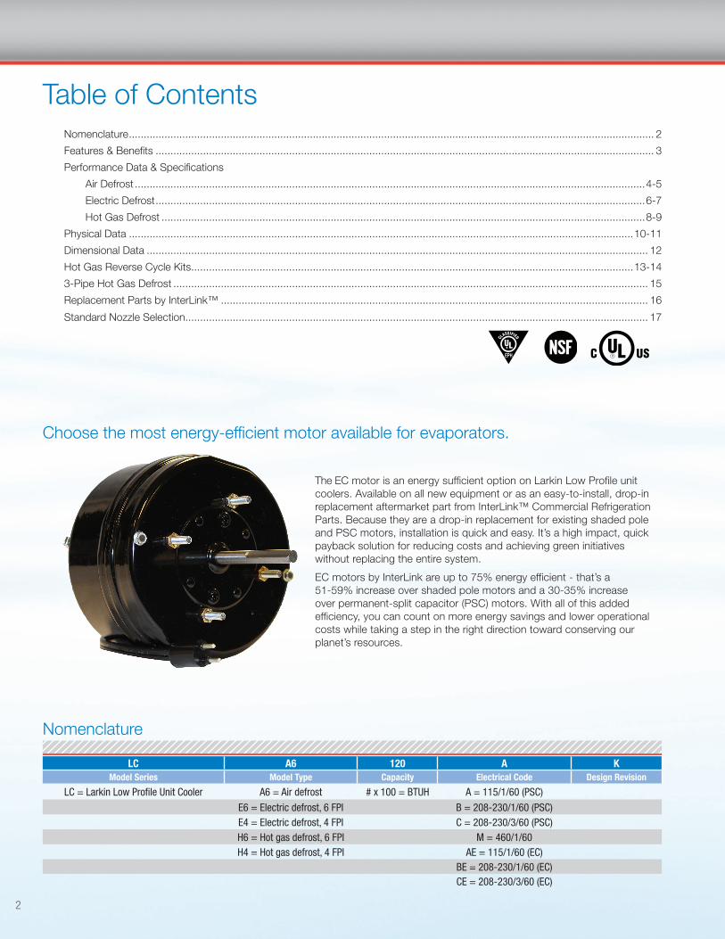
Choose the most energy-efficient motor available for evaporators�
The EC motor is an energy sufficient option on Larkin Low Profile unit coolers� Available on all new equipment or as an easy-to-install, drop-in replacement aftermarket part from InterLink™ Commercial Refrigeration Parts� Because they are a drop-in replacement for existing shaded pole and PSC motors, installation is quick and easy� It’s a high impact, quick payback solution for reducing costs and achieving green initiatives without replacing the entire system�
EC motors by InterLink are up to 75% energy efficient - that’s a 51-59% increase over shaded pole motors and a 30-35% increase over permanent-split capacitor (PSC) motors� With all of this added efficiency, you can count on more energy savings and lower operational costs while taking a step in the right direction toward conserving our planet’s resources�
3
LOW PROFILE UNIT COOLER
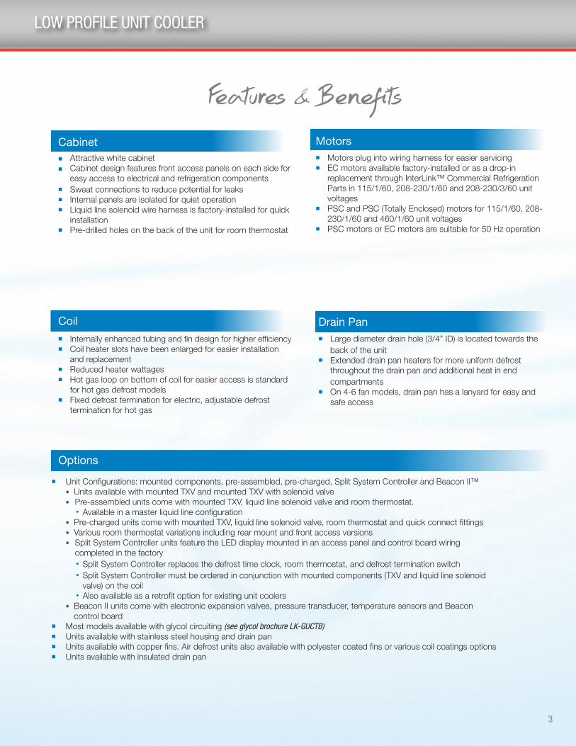
Features & BenefitsCabinet n Attractive white cabinetn Cabinet design features front access panels on each side for
easy access to electrical and refrigeration componentsn Sweat connections to reduce potential for leaksn Internal panels are isolated for quiet operationn Liquid line solenoid wire harness is factory-installed for quick
installationn Pre-drilled holes on the back of the unit for room thermostat
Drain Pann Large diameter drain hole (3/4” ID) is located towards the
back of the unitn Extended drain pan heaters for more uniform defrost
throughout the drain pan and additional heat in end compartments
n On 4-6 fan models, drain pan has a lanyard for easy and safe access
Coiln Internally enhanced tubing and fin design for higher efficiencyn Coil heater slots have been enlarged for easier installation
and replacementn Reduced heater wattagesn Hot gas loop on bottom of coil for easier access is standard
for hot gas defrost modelsn Fixed defrost termination for electric, adjustable defrost
termination for hot gas
Motors n Motors plug into wiring harness for easier servicingn EC motors available factory-installed or as a drop-in
replacement through InterLink™ Commercial Refrigeration Parts in 115/1/60, 208-230/1/60 and 208-230/3/60 unit voltages
n PSC and PSC (Totally Enclosed) motors for 115/1/60, 208-230/1/60 and 460/1/60 unit voltages
n PSC motors or EC motors are suitable for 50 Hz operation
n Unit Configurations: mounted components, pre-assembled, pre-charged, Split System Controller and Beacon II™ l Units available with mounted TXV and mounted TXV with solenoid valve l Pre-assembled units come with mounted TXV, liquid line solenoid valve and room thermostat� l Available in a master liquid line configuration l Pre-charged units come with mounted TXV, liquid line solenoid valve, room thermostat and quick connect fittings l Various room thermostat variations including rear mount and front access versions l Split System Controller units feature the LED display mounted in an access panel and control board wiring
completed in the factory l Split System Controller replaces the defrost time clock, room thermostat, and defrost termination switch l Split System Controller must be ordered in conjunction with mounted components (TXV and liquid line solenoid
valve) on the coil l Also available as a retrofit option for existing unit coolers
l Beacon II units come with electronic expansion valves, pressure transducer, temperature sensors and Beacon control board
n Most models available with glycol circuiting (see glycol brochure LK-GUCTB)n Units available with stainless steel housing and drain pann Units available with copper fins� Air defrost units also available with polyester coated fins or various coil coatings optionsn Units available with insulated drain pan
Options

4
Model
Capacity Fan Data
10°F TD25°F SST
6°C TD-4°C SST No. CFM m3H
BTUH Watts
LCA640 4,000 1,170 1 730 1,240
LCA651 5,100 1,500 1 700 1,189
LCA662 6,200 1,820 1 650 1,104
LCA672 7,200 2,110 2 1,460 2,481
LCA690 9,000 2,640 2 1,400 2,379
LCA6110 11,000 3,220 2 1,300 2,209
LCA6135 13,500 3,950 3 2,100 3,568
LCA6160 16,000 4,690 3 1,950 3,313
LCA6185 18,500 5,420 4 2,800 4,758
LCA6215 21,500 6,290 4 2,600 4,418
LCA6260 26,000 7,610 5 3,250 5,522
LCA6310 31,000 9,070 6 3,900 6,627
LCA6350 35,000 10,240 6 3,900 6,627
Model
Capacity Fan Data
10°F TD25°F SST
6°C TD-4°C SST No. CFM m3H
BTUH Watts
LCA640 3,800 1,112 1 670 1,117
LCA651 4,845 1,417 1 630 1,071
LCA662 5,890 1,723 1 586 995
LCA672 6,840 2,001 2 1,315 2,234
LCA690 8,550 2,502 2 1,260 2,142
LCA6110 10,450 3,057 2 1,170 1,989
LCA6135 12,825 3,752 3 1,891 3,213
LCA6160 19,200 4,447 3 1,756 2,984
LCA6185 17,575 5,142 4 2,521 4,284
LCA6215 20,425 5,976 4 2,341 3,978
LCA6260 24,700 7,226 5 2,927 4,973
LCA6310 29,450 8,616 6 3,512 5,967
LCA6350 33,250 9,728 6 3,512 5,967
Model LCA6 Air Defrost | 60 Hz
Model LCA6 Air Defrost | 50 Hz †
PERFORMANCE DATA: AIR DEFROST
† For EC motors, use 60 Hz capacity and airflow values (Units with EC motors operating at 50 Hz will not see a reduction in performance due to the electronic control of the motor)
5
Model HP
PSC Motor EC Motor
110/1/50 220/1/50 380/1/50 110/1/50 220/1/50
Amps Watts Amps Watts Amps Watts Amps Watts Amps Watts
LCA640 1/15 1.0 68 0.5 65 0.4 82 1.1 57 0.6 59
LCA651 1/15 1.0 68 0.5 65 0.4 82 1.1 57 0.6 59
LCA662 1/15 1.0 68 0.5 65 0.4 82 1.1 57 0.6 59
LCA672 1/15 2.0 136 1.0 130 0.8 164 2.0 114 1.1 118
LCA690 1/15 2.0 136 1.0 130 0.8 164 2.0 114 1.1 118
LCA6110 1/15 2.0 136 1.0 130 0.8 164 2.0 114 1.1 118
LCA6135 1/15 3.0 204 1.5 195 1.2 246 2.9 171 1.6 177
LCA6160 1/15 3.0 204 1.5 195 1.2 246 2.9 171 1.6 177
LCA6185 1/15 4.0 272 2.0 260 1.6 328 3.8 228 2.1 236
LCA6215 1/15 4.0 272 2.0 260 1.6 328 3.8 228 2.1 236
LCA6260 1/15 5.0 340 2.5 325 2.0 410 4.7 285 2.6 295
LCA6310 1/15 6.0 408 3.0 390 2.4 492 5.6 342 3.1 354
LCA6350 1/15 6.0 408 3.0 390 2.4 492 5.6 342 3.1 354
Model HP
Shaded Pole Motor PSC, PSC-TE Motor EC Motor
115/1/60 208-230/1/60 115/1/60 208-230/1/60 460/1/60 115/1/60 208-230/1/60
Amps Watts Amps Watts Amps Watts Amps Watts Amps Watts Amps Watts Amps Watts
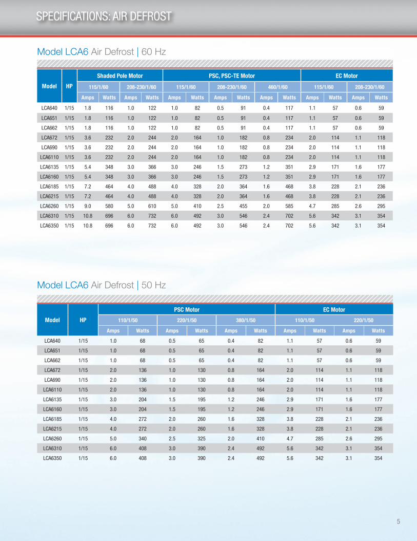
LCA640 1/15 1.8 116 1.0 122 1.0 82 0.5 91 0.4 117 1.1 57 0.6 59
LCA651 1/15 1.8 116 1.0 122 1.0 82 0.5 91 0.4 117 1.1 57 0.6 59
LCA662 1/15 1.8 116 1.0 122 1.0 82 0.5 91 0.4 117 1.1 57 0.6 59
LCA672 1/15 3.6 232 2.0 244 2.0 164 1.0 182 0.8 234 2.0 114 1.1 118
LCA690 1/15 3.6 232 2.0 244 2.0 164 1.0 182 0.8 234 2.0 114 1.1 118
LCA6110 1/15 3.6 232 2.0 244 2.0 164 1.0 182 0.8 234 2.0 114 1.1 118
LCA6135 1/15 5.4 348 3.0 366 3.0 246 1.5 273 1.2 351 2.9 171 1.6 177
LCA6160 1/15 5.4 348 3.0 366 3.0 246 1.5 273 1.2 351 2.9 171 1.6 177
LCA6185 1/15 7.2 464 4.0 488 4.0 328 2.0 364 1.6 468 3.8 228 2.1 236
LCA6215 1/15 7.2 464 4.0 488 4.0 328 2.0 364 1.6 468 3.8 228 2.1 236
LCA6260 1/15 9.0 580 5.0 610 5.0 410 2.5 455 2.0 585 4.7 285 2.6 295
LCA6310 1/15 10.8 696 6.0 732 6.0 492 3.0 546 2.4 702 5.6 342 3.1 354
LCA6350 1/15 10.8 696 6.0 732 6.0 492 3.0 546 2.4 702 5.6 342 3.1 354
SPECIFICATIONS: AIR DEFROST
Model LCA6 Air Defrost | 60 Hz
Model LCA6 Air Defrost | 50 Hz

6
PERFORMANCE DATA : ELECTRIC DEFROST
Model
Capacity Fan Data10°F TD
-20°F SST6°C TD
-29°C SST No. CFM m3HBTUH Watts
6 Fi
ns P
er In
ch
LCE635 3,325 973 1 630 1,071
LCE643 4,085 1,195 1 586 995
LCE665 6,175 1,807 2 1,261 2,142
LCE676 7,220 2,112 2 1,171 1,989
LCE694 8,930 2,613 2 1,171 1,989
LCE6120 11,400 3,335 3 1,891 3,213
LCE6140 13,300 3,891 3 1,756 2,984
LCE6160 15,200 4,447 4 2,341 3,978
LCE6180 17,100 5,003 4 2,341 3,978
LCE6200 19,000 5,559 5 2,927 4,973
LCE6240 22,800 6,671 6 3,512 5,967
LCE6270 25,650 7,504 6 3,512 5,967
LCE441 3,895 1,140 1 621 1,056
4 Fi
ns P
er In
ch
LCE457 5,415 1,584 2 1,297 2,203
LCE467 6,365 1,862 2 1,243 2,111
LCE482 7,790 2,279 2 1,243 2,111
LCE4105 9,975 2,918 3 1,954 3,320
LCE4139 13,205 3,863 4 2,485 4,223
LCE4174 16,530 4,836 5 3,107 5,279
LCE4208 19,760 5,781 6 3,728 6,334
LCE4235 22,325 6,532 6 3,728 6,334
† For EC motors, use 60 Hz capacity and airflow values (Units with EC motors operating at 50 Hz will not see a reduction in performance due to the electronic control of the motor)
Model LCE6/LCE4 Eletric Defrost | 60 Hz
Model LCE6/LCE4 Eletric Defrost | 50 Hz †
Model
Capacity Fan Data10°F TD
-20°F SST6°C TD
-29°C SST No. CFM m3HBTUH Watts
6 Fi
ns P
er In
ch
LCE635 3,500 1,030 1 700 1,189
LCE643 4,300 1,260 1 650 1,104
LCE665 6,500 1,900 2 1,400 2,379
LCE676 7,600 2,230 2 1,300 2,209
LCE694 9,400 2,750 2 1,300 2,209
LCE6120 12,000 3,520 3 2,100 3,568
LCE6140 14,000 4,100 3 1,950 3,313
LCE6160 16,000 4,690 4 2,600 4,418
LCE6180 18,000 5,270 4 2,600 4,418
LCE6200 20,000 5,860 5 3,250 5,522
LCE6240 24,000 7,030 6 3,900 6,627
LCE6270 27,000 7,900 6 3,900 6,627
LCE441 4,100 1,200 1 690 1,172
4 Fi
ns P
er In
ch
LCE457 5,700 1,670 2 1,440 2,447
LCE467 6,700 1,960 2 1,380 2,345
LCE482 8,200 2,400 2 1,380 2,345
LCE4105 10,500 3,080 3 2,170 3,687
LCE4139 13,900 4,070 4 2,760 4,690
LCE4174 17,400 5,100 5 3,450 5,862
LCE4208 20,800 6,090 6 4,140 7,035
LCE4235 23,500 6,880 6 4,140 7,035
Saturated Suction Temperature °F
+20 -10 -20 -30
Saturated Suction Temperature °C
-7 -23 -29 -34
Multiply Capacity By 1.15 1.04 1.00 0.90
Capacity Correction Factors for Electric and Hot Gas Defrost Units
7
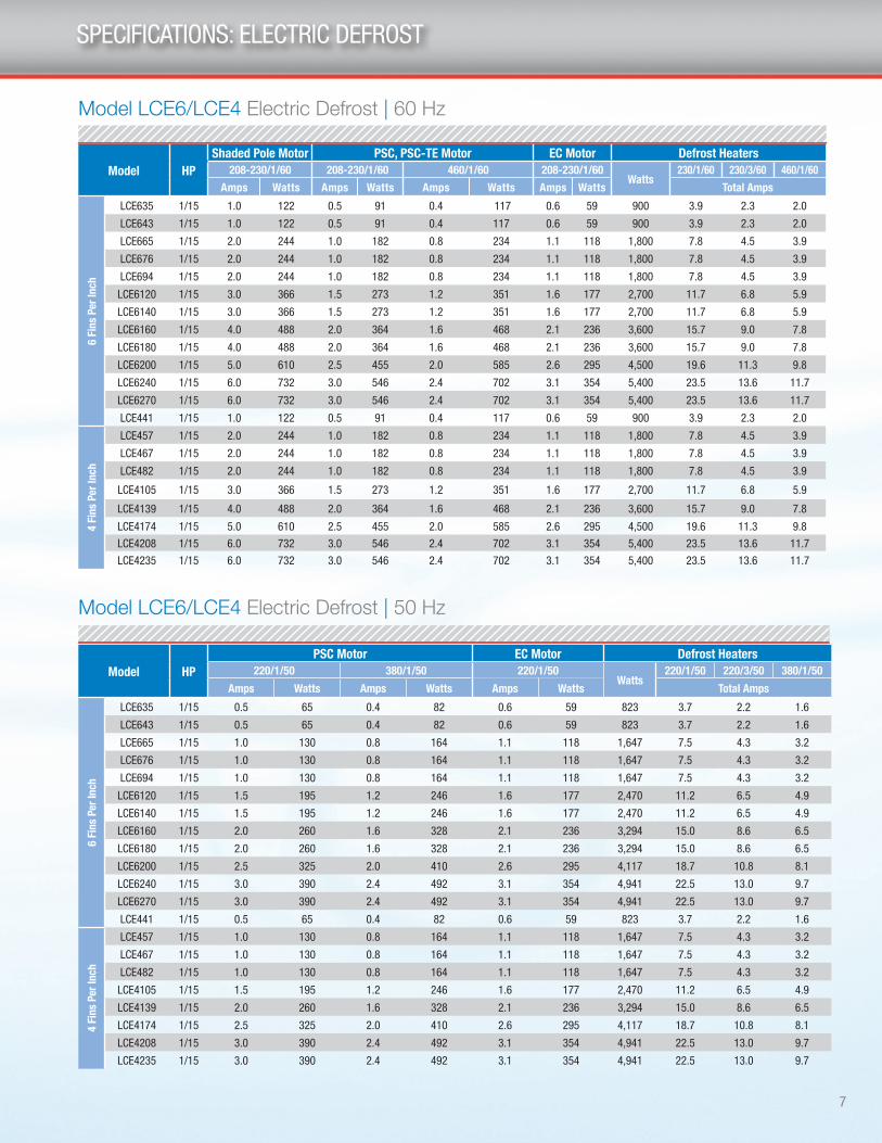
SPECIFICATIONS: ELECTRIC DEFROST
Model HPShaded Pole Motor PSC, PSC-TE Motor EC Motor Defrost Heaters
208-230/1/60 208-230/1/60 460/1/60 208-230/1/60 Watts
230/1/60 230/3/60 460/1/60
Total AmpsAmps Watts Amps Watts Amps Watts Amps Watts
6 Fi
ns P
er In
ch
LCE635 1/15 1.0 122 0.5 91 0.4 117 0.6 59 900 3.9 2.3 2.0
LCE643 1/15 1.0 122 0.5 91 0.4 117 0.6 59 900 3.9 2.3 2.0
LCE665 1/15 2.0 244 1.0 182 0.8 234 1.1 118 1,800 7.8 4.5 3.9
LCE676 1/15 2.0 244 1.0 182 0.8 234 1.1 118 1,800 7.8 4.5 3.9
LCE694 1/15 2.0 244 1.0 182 0.8 234 1.1 118 1,800 7.8 4.5 3.9
LCE6120 1/15 3.0 366 1.5 273 1.2 351 1.6 177 2,700 11.7 6.8 5.9
LCE6140 1/15 3.0 366 1.5 273 1.2 351 1.6 177 2,700 11.7 6.8 5.9
LCE6160 1/15 4.0 488 2.0 364 1.6 468 2.1 236 3,600 15.7 9.0 7.8
LCE6180 1/15 4.0 488 2.0 364 1.6 468 2.1 236 3,600 15.7 9.0 7.8
LCE6200 1/15 5.0 610 2.5 455 2.0 585 2.6 295 4,500 19.6 11.3 9.8
LCE6240 1/15 6.0 732 3.0 546 2.4 702 3.1 354 5,400 23.5 13.6 11.7
LCE6270 1/15 6.0 732 3.0 546 2.4 702 3.1 354 5,400 23.5 13.6 11.7
LCE441 1/15 1.0 122 0.5 91 0.4 117 0.6 59 900 3.9 2.3 2.0
4 Fi
ns P
er In
ch
LCE457 1/15 2.0 244 1.0 182 0.8 234 1.1 118 1,800 7.8 4.5 3.9
LCE467 1/15 2.0 244 1.0 182 0.8 234 1.1 118 1,800 7.8 4.5 3.9
LCE482 1/15 2.0 244 1.0 182 0.8 234 1.1 118 1,800 7.8 4.5 3.9
LCE4105 1/15 3.0 366 1.5 273 1.2 351 1.6 177 2,700 11.7 6.8 5.9
LCE4139 1/15 4.0 488 2.0 364 1.6 468 2.1 236 3,600 15.7 9.0 7.8
LCE4174 1/15 5.0 610 2.5 455 2.0 585 2.6 295 4,500 19.6 11.3 9.8
LCE4208 1/15 6.0 732 3.0 546 2.4 702 3.1 354 5,400 23.5 13.6 11.7
LCE4235 1/15 6.0 732 3.0 546 2.4 702 3.1 354 5,400 23.5 13.6 11.7
Model HPPSC Motor EC Motor Defrost Heaters
220/1/50 380/1/50 220/1/50Watts
220/1/50 220/3/50 380/1/50
Amps Watts Amps Watts Amps Watts Total Amps
6 Fi
ns P
er In
ch
LCE635 1/15 0.5 65 0.4 82 0.6 59 823 3.7 2.2 1.6
LCE643 1/15 0.5 65 0.4 82 0.6 59 823 3.7 2.2 1.6
LCE665 1/15 1.0 130 0.8 164 1.1 118 1,647 7.5 4.3 3.2
LCE676 1/15 1.0 130 0.8 164 1.1 118 1,647 7.5 4.3 3.2
LCE694 1/15 1.0 130 0.8 164 1.1 118 1,647 7.5 4.3 3.2
LCE6120 1/15 1.5 195 1.2 246 1.6 177 2,470 11.2 6.5 4.9
LCE6140 1/15 1.5 195 1.2 246 1.6 177 2,470 11.2 6.5 4.9
LCE6160 1/15 2.0 260 1.6 328 2.1 236 3,294 15.0 8.6 6.5
LCE6180 1/15 2.0 260 1.6 328 2.1 236 3,294 15.0 8.6 6.5
LCE6200 1/15 2.5 325 2.0 410 2.6 295 4,117 18.7 10.8 8.1
LCE6240 1/15 3.0 390 2.4 492 3.1 354 4,941 22.5 13.0 9.7
LCE6270 1/15 3.0 390 2.4 492 3.1 354 4,941 22.5 13.0 9.7
LCE441 1/15 0.5 65 0.4 82 0.6 59 823 3.7 2.2 1.6
4 Fi
ns P
er In
ch
LCE457 1/15 1.0 130 0.8 164 1.1 118 1,647 7.5 4.3 3.2
LCE467 1/15 1.0 130 0.8 164 1.1 118 1,647 7.5 4.3 3.2
LCE482 1/15 1.0 130 0.8 164 1.1 118 1,647 7.5 4.3 3.2
LCE4105 1/15 1.5 195 1.2 246 1.6 177 2,470 11.2 6.5 4.9
LCE4139 1/15 2.0 260 1.6 328 2.1 236 3,294 15.0 8.6 6.5
LCE4174 1/15 2.5 325 2.0 410 2.6 295 4,117 18.7 10.8 8.1
LCE4208 1/15 3.0 390 2.4 492 3.1 354 4,941 22.5 13.0 9.7
LCE4235 1/15 3.0 390 2.4 492 3.1 354 4,941 22.5 13.0 9.7
Model LCE6/LCE4 Electric Defrost | 50 Hz
Model LCE6/LCE4 Electric Defrost | 60 Hz

8
PERFORMANCE DATA : HOT GAS DEFROST
Model
Capacity Fan Data
10°F TD-20°F SST
6°C TD-29°C SST No. CFM m3H
BTUH Watts
6 Fi
ns P
er In
ch
LCH635 3,500 1,030 1 700 1,189LCH643 4,300 1,260 1 650 1,104LCH665 6,500 1,900 2 1,400 2,379LCH676 7,600 2,230 2 1,300 2,209LCH694 9,400 2,750 2 1,300 2,209LCH6120 12,000 3,520 3 2,100 3,568LCH6140 14,000 4,100 3 1,950 3,313LCH6160 16,000 4,690 4 2,600 4,418LCH6180 18,000 5,270 4 2,600 4,418LCH6200 20,000 5,860 5 3,250 5,522LCH6240 24,000 7,030 6 3,900 6,627LCH6270 27,000 7,900 6 3,900 6,627LCH441 4,100 1,200 1 690 1,172
4 Fi
ns P
er In
ch
LCH457 5,700 1,670 2 1,440 2,447LCH467 6,700 1,960 2 1,380 2,345LCH482 8,200 2,400 2 1,380 2,345LCH4105 10,500 3,080 3 2,170 3,687LCH4139 13,900 4,070 4 2,760 4,690
LCH4174 17,400 5,100 5 3,450 5,862
LCH4208 20,800 6,090 6 4,140 7,035LCH4235 23,500 6,880 6 4,140 7,035
Model
Capacity Fan Data
10°F TD-20°F SST
6°C TD-29°C SST No. CFM m3H
BTUH Watts
6 Fi
ns P
er In
ch
LCH635 3,325 973 1 630 1,070LCH643 4,085 1,195 1 586 995LCH665 6,175 1,802 2 1,261 2,142LCH676 7,220 2,112 2 1,171 1,989LCH694 8,930 2,613 2 1,171 1,989
LCH6120 11,400 3,335 3 1,891 3,213LCH6140 13,300 3,891 3 1,756 2,984LCH6160 15,200 4,447 4 2,341 3,978LCH6180 17,100 5,003 4 2,341 3,978LCH6200 19,000 5,559 5 2,927 4,973LCH6240 22,800 6,671 6 3,512 5,967LCH6270 25,650 7,504 6 3,512 5,967LCH441 3,895 1,140 1 621 1,056
4 Fi
ns P
er In
ch
LCH457 5,415 1,584 2 1,297 2,203LCH467 6,365 1,862 2 1,243 2,111LCH482 7,790 2,279 2 1,243 2,111
LCH4105 9,975 2,918 3 1,954 3,320LCH4139 13,205 3,863 4 2,485 4,223LCH4174 16,530 4,836 5 3,107 5,279LCH4208 19,760 5,781 6 3,728 6,334LCH4235 22,325 6,532 6 3,728 6,334
NOTE: When using the hot gas units with a hot gas loop drain pan on 0°F applications and below, an insulated drain pan is required.
Capacity Correction Factors For Electric and Hot Gas Defrost UnitsSaturated Suction Temperature °F +20 -10 -20 -30
Saturated Suction Temperature °C -7 -23 -29 -34
Multiply Capacity By 1.15 1.04 1.00 0.90
Model LCH6/LCH4 Hot Gas Defrost | 60 Hz
Model LCH6/LCH4 Hot Gas Defrost | 50 Hz †
† For EC motors, use 60 Hz capacity and airflow values (Units with EC motors operating at 50 Hz will not see a reduction in performance due to the electronic control of the motor)
9
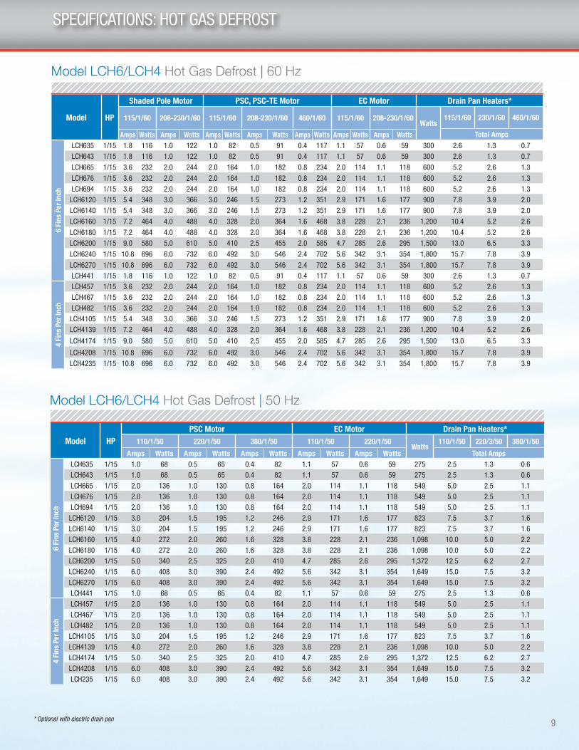
SPECIFICATIONS: HOT GAS DEFROST
Model HP
Shaded Pole Motor PSC, PSC-TE Motor EC Motor Drain Pan Heaters*
115/1/60 208-230/1/60 115/1/60 208-230/1/60 460/1/60 115/1/60 208-230/1/60 Watts
115/1/60 230/1/60 460/1/60
Total AmpsAmps Watts Amps Watts Amps Watts Amps Watts Amps Watts Amps Watts Amps Watts
6 Fi
ns P
er In
ch
LCH635 1/15 1.8 116 1.0 122 1.0 82 0.5 91 0.4 117 1.1 57 0.6 59 300 2.6 1.3 0.7LCH643 1/15 1.8 116 1.0 122 1.0 82 0.5 91 0.4 117 1.1 57 0.6 59 300 2.6 1.3 0.7
LCH665 1/15 3.6 232 2.0 244 2.0 164 1.0 182 0.8 234 2.0 114 1.1 118 600 5.2 2.6 1.3
LCH676 1/15 3.6 232 2.0 244 2.0 164 1.0 182 0.8 234 2.0 114 1.1 118 600 5.2 2.6 1.3LCH694 1/15 3.6 232 2.0 244 2.0 164 1.0 182 0.8 234 2.0 114 1.1 118 600 5.2 2.6 1.3LCH6120 1/15 5.4 348 3.0 366 3.0 246 1.5 273 1.2 351 2.9 171 1.6 177 900 7.8 3.9 2.0LCH6140 1/15 5.4 348 3.0 366 3.0 246 1.5 273 1.2 351 2.9 171 1.6 177 900 7.8 3.9 2.0
LCH6160 1/15 7.2 464 4.0 488 4.0 328 2.0 364 1.6 468 3.8 228 2.1 236 1,200 10.4 5.2 2.6
LCH6180 1/15 7.2 464 4.0 488 4.0 328 2.0 364 1.6 468 3.8 228 2.1 236 1,200 10.4 5.2 2.6LCH6200 1/15 9.0 580 5.0 610 5.0 410 2.5 455 2.0 585 4.7 285 2.6 295 1,500 13.0 6.5 3.3
LCH6240 1/15 10.8 696 6.0 732 6.0 492 3.0 546 2.4 702 5.6 342 3.1 354 1,800 15.7 7.8 3.9
LCH6270 1/15 10.8 696 6.0 732 6.0 492 3.0 546 2.4 702 5.6 342 3.1 354 1,800 15.7 7.8 3.9LCH441 1/15 1.8 116 1.0 122 1.0 82 0.5 91 0.4 117 1.1 57 0.6 59 300 2.6 1.3 0.7
4 Fi
ns P
er In
ch
LCH457 1/15 3.6 232 2.0 244 2.0 164 1.0 182 0.8 234 2.0 114 1.1 118 600 5.2 2.6 1.3LCH467 1/15 3.6 232 2.0 244 2.0 164 1.0 182 0.8 234 2.0 114 1.1 118 600 5.2 2.6 1.3LCH482 1/15 3.6 232 2.0 244 2.0 164 1.0 182 0.8 234 2.0 114 1.1 118 600 5.2 2.6 1.3LCH4105 1/15 5.4 348 3.0 366 3.0 246 1.5 273 1.2 351 2.9 171 1.6 177 900 7.8 3.9 2.0LCH4139 1/15 7.2 464 4.0 488 4.0 328 2.0 364 1.6 468 3.8 228 2.1 236 1,200 10.4 5.2 2.6
LCH4174 1/15 9.0 580 5.0 610 5.0 410 2.5 455 2.0 585 4.7 285 2.6 295 1,500 13.0 6.5 3.3
LCH4208 1/15 10.8 696 6.0 732 6.0 492 3.0 546 2.4 702 5.6 342 3.1 354 1,800 15.7 7.8 3.9
LCH4235 1/15 10.8 696 6.0 732 6.0 492 3.0 546 2.4 702 5.6 342 3.1 354 1,800 15.7 7.8 3.9
Model HPPSC Motor EC Motor Drain Pan Heaters*
110/1/50 220/1/50 380/1/50 110/1/50 220/1/50 Watts
110/1/50 220/3/50 380/1/50
Amps Watts Amps Watts Amps Watts Amps Watts Amps Watts Total Amps
6 Fi
ns P
er In
ch
LCH635 1/15 1.0 68 0.5 65 0.4 82 1.1 57 0.6 59 275 2.5 1.3 0.6LCH643 1/15 1.0 68 0.5 65 0.4 82 1.1 57 0.6 59 275 2.5 1.3 0.6LCH665 1/15 2.0 136 1.0 130 0.8 164 2.0 114 1.1 118 549 5.0 2.5 1.1LCH676 1/15 2.0 136 1.0 130 0.8 164 2.0 114 1.1 118 549 5.0 2.5 1.1LCH694 1/15 2.0 136 1.0 130 0.8 164 2.0 114 1.1 118 549 5.0 2.5 1.1LCH6120 1/15 3.0 204 1.5 195 1.2 246 2.9 171 1.6 177 823 7.5 3.7 1.6LCH6140 1/15 3.0 204 1.5 195 1.2 246 2.9 171 1.6 177 823 7.5 3.7 1.6LCH6160 1/15 4.0 272 2.0 260 1.6 328 3.8 228 2.1 236 1,098 10.0 5.0 2.2LCH6180 1/15 4.0 272 2.0 260 1.6 328 3.8 228 2.1 236 1,098 10.0 5.0 2.2LCH6200 1/15 5.0 340 2.5 325 2.0 410 4.7 285 2.6 295 1,372 12.5 6.2 2.7LCH6240 1/15 6.0 408 3.0 390 2.4 492 5.6 342 3.1 354 1,649 15.0 7.5 3.2LCH6270 1/15 6.0 408 3.0 390 2.4 492 5.6 342 3.1 354 1,649 15.0 7.5 3.2LCH441 1/15 1.0 68 0.5 65 0.4 82 1.1 57 0.6 59 275 2.5 1.3 0.6
4 Fi
ns P
er In
ch
LCH457 1/15 2.0 136 1.0 130 0.8 164 2.0 114 1.1 118 549 5.0 2.5 1.1LCH467 1/15 2.0 136 1.0 130 0.8 164 2.0 114 1.1 118 549 5.0 2.5 1.1LCH482 1/15 2.0 136 1.0 130 0.8 164 2.0 114 1.1 118 549 5.0 2.5 1.1LCH4105 1/15 3.0 204 1.5 195 1.2 246 2.9 171 1.6 177 823 7.5 3.7 1.6LCH4139 1/15 4.0 272 2.0 260 1.6 328 3.8 228 2.1 236 1,098 10.0 5.0 2.2LCH4174 1/15 5.0 340 2.5 325 2.0 410 4.7 285 2.6 295 1,372 12.5 6.2 2.7LCH4208 1/15 6.0 408 3.0 390 2.4 492 5.6 342 3.1 354 1,649 15.0 7.5 3.2LCH235 1/15 6.0 408 3.0 390 2.4 492 5.6 342 3.1 354 1,649 15.0 7.5 3.2
Model LCH6/LCH4 Hot Gas Defrost | 60 Hz
Model LCH6/LCH4 Hot Gas Defrost | 50 Hz
* Optional with electric drain pan

10
PHYSICAL DATA
ModelNo. ofFans
Connections (in.) Approx. Net Wt.
Coil Inlet OD Suction ODExternal
Equalizer OD Drain MPT lbs. kg
LCA640 1 1/2 5/8 1/4 3/4 28 13
LCA651 1 1/2 5/8 1/4 3/4 31 15
LCA662 1 1/2 7/8 1/4 3/4 34 16
LCA672 2 1/2 7/8 1/4 3/4 45 21
LCA690 2 1/2 7/8 1/4 3/4 49 23
LCA6110 2 1/2 7/8 1/4 3/4 51 24
LCA6135 3 1/2 7/8 1/4 3/4 67 31
LCA6160 3 1/2 7/8 1/4 3/4 69 32
LCA6185 4 1/2 1-1/8 1/4 3/4 82 38
LCA6215 4 1/2 1-1/8 1/4 3/4 84 39
LCA6260 5 1/2 1-1/8 1/4 3/4 103 47
LCA6310 6 1/2 1-1/8 1/4 3/4 124 57
LCA6350 6 1/2 1-3/8 1/4 3/4 127 58
ModelNo. ofFans
Connections (in.) Approx. Net Wt.
Coil InletOD
Suction ODExternal
Equalizer ODDrain MPT lbs. kg
6 Fi
ns P
er In
ch
LCE635 1 1/2 5/8 1/4 3/4 24 11
LCE643 1 1/2 5/8 1/4 3/4 29 14
LCE665 2 1/2 5/8 1/4 3/4 43 20
LCE676 2 1/2 7/8 1/4 3/4 45 21
LCE694 2 1/2 7/8 1/4 3/4 48 22
LCE6120 3 1/2 7/8 1/4 3/4 60 28
LCE6140 3 1/2 7/8 1/4 3/4 62 29
LCE6160 4 1/2 1-1/8 1/4 3/4 81 37
LCE6180 4 1/2 1-1/8 1/4 3/4 84 39
LCE6200 5 1/2 1-1/8 1/4 3/4 101 46
LCE6240 6 1/2 1-1/8 1/4 3/4 121 55
LCE6270 6 1/2 1-1/8 1/4 3/4 124 57
LCE441 1 1/2 5/8 1/4 3/4 28 13
4 Fi
ns P
er In
ch
LCE457 2 1/2 7/8 1/4 3/4 42 19
LCE467 2 1/2 7/8 1/4 3/4 44 20
LCE482 2 1/2 7/8 1/4 3/4 47 22
LCE4105 3 1/2 7/8 1/4 3/4 59 27
LCE4139 4 1/2 1-1/8 1/4 3/4 80 37
LCE4174 5 1/2 1-1/8 1/4 3/4 100 46
LCE4208 6 1/2 1-1/8 1/4 3/4 120 55
LCE4235 6 1/2 1-1/8 1/4 3/4 123 56
Model LCA6 Air Defrost
LCE6/LCE4 Electric Defrost

11
PHYSICAL DATA
The standard design for the Larkin low profile evaporators incorporates an efficient hot gas loop in the drain pan� Utilizing a hot gas loop is ideal for hot gas defrost applications where high temperature gas can be maintained to defrost both the evaporator drain pan and coil� For these models, an insulated drain pan is standard�
For applications where cooler (lower) temperature hot gas is used for defrosting, Larkin offers optional electric heater elements in the drain pan to ensure quick and efficient defrost of the drain pan allowing condensate to drain quickly, saving the hot gas for efficient evaporator coil defrost�
If the optional electric heating element drain pan is preferred, please specify when ordering, there is no additional charge�
* Hot Gas Loop Piping Connections
n For reverse cycle defrost piping:
• 5/8 ID Inlet
• 5/8 OD Outlet
n For 3-pipe defrost piping:
• 5/8 OD Inlet
• 5/8 ID Outlet
ModelNo. ofFans
Connections (in.)Approx. Net
Wt.
Coil InletOD
SuctionOD
External
Equalizer OD
DrainMPT
Side PortOD
Hot GasPan Conns.
ODlbs. kg
6 Fi
ns P
er In
ch
LCH635 1 5/8 5/8 1/4 3/8 5/8 26 12 12
LCH643 1 5/8 5/8 1/4 3/8 5/8 31 15 13
LCH665 2 5/8 5/8 1/4 3/8 5/8 45 21 15
LCH676 2 5/8 7/8 1/4 3/8 5/8 47 22 21
LCH694 2 7/8 7/8 1/4 3/8 5/8 50 23 22
LCH6120 3 7/8 7/8 1/4 3/8 5/8 62 29 23
LCH6140 3 7/8 7/8 1/4 3/8 5/8 64 30 29
LCH6160 4 7/8 1-1/8 1/4 3/8 5/8 83 38 30
LCH6180 4 1-1/8 1-1/8 1/4 3/8 5/8 86 40 38
LCH6200 5 1-1/8 1-1/8 1/4 3/8 5/8 103 47 40
LCH6240 6 1-1/8 1-1/8 1/4 3/8 5/8 123 56 47
LCH6270 6 1-1/8 1-1/8 1/4 3/8 5/8 126 57 56
LCH441 1 5/8 5/8 1/4 3/8 5/8 30 14 57
4 Fi
ns P
er In
ch
LCH457 2 5/8 7/8 1/4 3/8 5/8 44 20 14
LCH467 2 5/8 7/8 1/4 3/8 5/8 46 21 21
LCH482 2 5/8 7/8 1/4 3/8 5/8 49 23 23
LCH4105 3 7/8 7/8 1/4 3/8 5/8 61 28 28
LCH4139 4 7/8 1-1/8 1/4 3/8 5/8 82 38 38
LCH4174 5 7/8 1-1/8 1/4 3/8 5/8 102 47 47
LCH4208 6 7/8 1-1/8 1/4 3/8 5/8 122 56 56
LCH235 6 1-1/8 1-1/8 1/4 3/4 3/8 5/8 125 57
Model LCH6/LCH4 Hot Gas Defrost

12
DIMENSIONAL DATA
7/8"22mm
7/8" ElectricalKnockouts
2 1/8"54mm
1 1/2"38mm
1 3/4"44mm4 3/16"
106mm1 15/16"49mm2 1/4"
57mm
RefrigerantConnection
End
ElectricalConnection
End
"C" "D""B""A"
6 1/8"156mm
6 1/8"156mm
13 7/16"341mm
14 3/4"375mm
3/4" MPT (14 NPS)19mmDrain Connection
AIR FLOW12 3/8"314mm 16"
407mm
11 15/16"303mm
14 11/16"374mm
2 3/8"60mm
Air DefrostModel
Electric and Hot Gas
Defrost Model No. ofFans
Dimensions
6FPI 6FPI 4FPIA B C D
in mm in mm in mm in mm
640 - - 1 29.50 749.3 17.25 438.1 - - - -
651 635 - 1 29.50 749.3 17.25 438.1 - - - -
662 643 441 1 29.50 749.3 17.25 438.1 - - - -
672 - - 2 45.50 1,155.7 33.25 845 - - - -
- 665 457 2 45.50 1,155.7 33.25 845 - - - -
690 - - 2 45.50 1,155.7 33.25 845 - - - -
6110 676 467 2 45.50 1,155.7 33.25 845 - - - -
- 694 482 2 45.50 1,155.7 33.25 845 - - - -
- 6120 4105 3 61.50 1,562.1 49.25 1,251 - - - -
6135 - - 3 61.50 1,562.1 49.25 1,251 - - - -
6160 6140 - 3 61.50 1,562.1 49.25 1,251 - - - -
6185 6160 4139 4 77.50 1,968.5 65.25 1,657 - - - -
6215 6180 4139 4 77.50 1,968.5 65.25 1,657 - - - -
6260 6200 4274 5 93.50 2,374.9 81.25 2,064 48.63 1,235.1 32.63 828.7
6310 6240 4208 6 109.50 2,781.3 97.25 2,470 48.63 1,235.1 48.63 1,235.1
6350 6270 4235 6 109.50 2,781.3 97.25 2,470 48.63 1,235.1 48.63 1,235.1
NOTE: Hanger brackets will accept 3/8"/ 9.5 mm hanger rods.
Dimensional Data For All Models

13
441-482 50169210 50169213 50169216 52733701 52733704 52733707
4105-4208 50169211 50169214 50169217 52733702 52733705 52733708
4235 50169212 50169215 50169218 52733703 52733706 52733709
Shipped-loose Factory-installed
TXV Bypass Assembly Kits TXV Bypass Assembly Kits
LCH 6 FPI SQE/SBF EG HFESC SQE/SBF EG HFESC
LCH 4 FPI SQE/SBF EG HFESC SQE/SBF EG HFESC
635-676 50169210 50169213 50169216 52733701 52733704 52733707
694-6160 50169211 50169214 50169217 52733702 52733705 52733708
6180-6270 50169212 50169215 50169218 52733703 52733706 52733709
HOT GAS REVERSE CYCLE KITS
The hot gas unit coolers can be used in reverse cycle hot gas defrost systems using multiple evaporators connected to one condensing unit� Generally, not more than one-third of the system defrosts at one time�
During the reverse cycle defrost, the reversing valve, located in the compressor discharge line, diverts hot gas through the suction line to the evaporator� See piping view in Figure 1� The suction line check valve directs the hot gas through the drain pan loop which prevents condensate in the pan from freezing� The hot gas exits the loop at the pan loop outlet header and enters the evaporator through the check valve assembly� As the hot gas defrosts the coil, heat is removed from the hot gas and eventually it condenses into a liquid and exits the coil at the distributor sideport� The liquid then flows through the check valve of the thermostatic expansion valve bypass assembly, around the thermostatic expansion valve, and into the system liquid line� The liquid refrigerant then feeds other evaporators on the cooling cycle, evaporates, and returns to the compressor through their suction lines�
Recommendation is that both check valve kits are ordered (For hot gas models with the hot gas loop drain pan ONLY):
NOTE: The drain pan check valve kit can be ordered as an independent item� But the suction line check valve kit must be ordered with the drain pan check valve kit in order to complete the piping�
NOTE: When using the hot gas units with a hot gas loop drain pan on 0°F applications and below, an insulated drain pan is required.
Shipped-loose Factory-installed
Drain Pan LoopCheck Valve Kit
Suction LineCheck Valve Kit
Drain Pan LoopCheck Valve Kit
Suction LineCheck Valve Kit
50169304 50169304 52733601 52733801
50169305 50169305 52733602 52733802
50169306 50169306 52733603 52733802
50169304 50169304 52733801 52733801
50169305 50169305 52733802 52733802
50169306 50169306 52733802 52733802
LCH 6 FPI
635-676
694-6160
6180-6270
LCH 4 FPI
441-482
4105-4208
4235
14
HOT GAS REVERSE CYCLE KITS (cont.)
In the refrigeration cycle, the thermostatic expansion valve bypass assembly check valve only allows refrigerant flow through the thermostatic expansion valve and into the evaporator coil� As the refrigerant vapor exits the coil at the suction line, the check valve of the drain pan loop check valve assembly prevents the refrigerant vapor flow through the drain pan loop�
Factory-engineered assemblies (kits) are available for both shipped-loose and factory-installed at an additional cost to complete the reverse cycle piping and components� The suction line check valve assembly includes the suction line check valve and the piping for both the suction line and the connection to the drain pan loop inlet header� In order for the suction line check valve assembly to be mounted, the drain pan loop check valve assembly must be used� The drain pan loop check valve assembly includes the check valve, suction line tee and a bent pipe� The thermostatic expansion valve bypass assembly option includes the check valve, tee and necessary piping� In order for the thermostatic expansion valve bypass assembly option to be complete, a thermostatic expansion valve must be selected by the sales engineer� The thermostatic expansion valve bypass assembly option is dependent on the body style of the thermostatic expansion valves which includes the Sporlan® SQE, SBF, EG and the Flow Controls HFESC body styles� The factory-installed thermostatic expansion valve bypass assembly option must have the thermostatic expansion valve selection included on the order for the hot gas unit cooler�
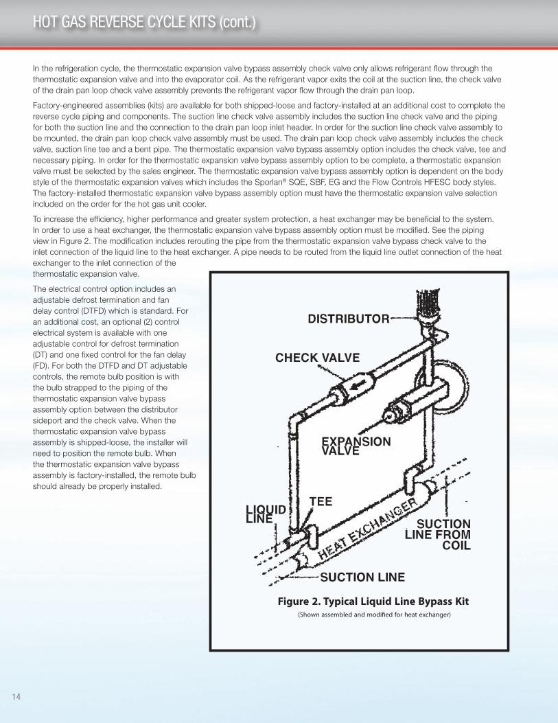
To increase the efficiency, higher performance and greater system protection, a heat exchanger may be beneficial to the system� In order to use a heat exchanger, the thermostatic expansion valve bypass assembly option must be modified� See the piping view in Figure 2� The modification includes rerouting the pipe from the thermostatic expansion valve bypass check valve to the inlet connection of the liquid line to the heat exchanger� A pipe needs to be routed from the liquid line outlet connection of the heat exchanger to the inlet connection of the thermostatic expansion valve�
The electrical control option includes an adjustable defrost termination and fan delay control (DTFD) which is standard� For an additional cost, an optional (2) control electrical system is available with one adjustable control for defrost termination (DT) and one fixed control for the fan delay (FD)� For both the DTFD and DT adjustable controls, the remote bulb position is with the bulb strapped to the piping of the thermostatic expansion valve bypass assembly option between the distributor sideport and the check valve� When the thermostatic expansion valve bypass assembly is shipped-loose, the installer will need to position the remote bulb� When the thermostatic expansion valve bypass assembly is factory-installed, the remote bulb should already be properly installed�
15
Shipped-loose Factory-installed
Drain Pan Loop Check Valve Kit Drain Pan Loop Check Valve Kit
LCH 6 FPI
LCH 4 FPI
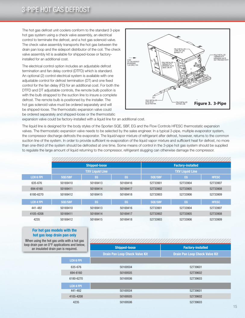
3-PIPE HOT GAS DEFROST
The hot gas defrost unit coolers conform to the standard 3-pipe hot gas system using a check valve assembly, an electrical control to terminate the defrost, and a hot gas solenoid valve� The check valve assembly transports the hot gas between the drain pan loop and the sideport distributor of the coil� The check valve assembly kit is available for shipped-loose or factory-installed for an additional cost�
The electrical control option includes an adjustable defrost termination and fan delay control (DTFD) which is standard� An optional (2) control electrical system is available with one adjustable control for defrost termination (DT) and one fixed control for the fan delay (FD) for an additional cost� For both the DTFD and DT adjustable controls, the remote bulb position is with the bulb strapped to the suction line to insure a complete defrost� The remote bulb is positioned by the installer� The hot gas solenoid valve must be ordered separately and will be shipped-loose� The thermostatic expansion valve could be ordered separately and shipped-loose or the thermostatic expansion valve could be factory-installed with a liquid line for an additional cost�
The liquid line is designed for the body styles of the Sporlan SQE, SBF, EG and the Flow Controls HFESC thermostatic expansion valves� The thermostatic expansion valve needs to be selected by the sales engineer� In a typical 3-pipe, multiple evaporator system, the compressor discharge defrosts the evaporator� The liquid/vapor mixture of refrigerant after defrost, however, returns to the common suction line of the system� In order to provide sufficient re-evaporation of the liquid vapor mixture and sufficient heat for defrost, no more than one-third of the system should be defrosted at one time� Some means of control in the 3-pipe hot gas system should be supplied to regulate the large amount of liquid returning to the compressor, refrigerant slugging can otherwise damage the compressor�
Shipped-loose Factory-installed
TXV Liquid Line TXV Liquid Line
LCH 6 FPI SQE/SBF EG EG SQE/SBF EG HFESC
LCH 4 FPI SQE/SBF EG EG SQE/SBF EG HFESC
635-676 50169410 50169413 50169416 52733901 52733904 52733907
694-6160 50169411 50169414 50169417 52733902 52733905 52733908
6180-6270 50169412 50169415 50169418 52733903 52733906 52733909
441-482 50169410 50169413 50169416 52733901 52733904 52733907
4105-4208 50169411 50169414 50169417 52733902 52733905 52733908
4235 50169412 50169415 50169418 52733903 52733906 52733909
635-676 50169504 52739601
694-6160 50169505 52739602
6180-6270 50169506 52739603
441-482 50169504 52739601
4105-4208 50169505 52739602
4235 50169506 52739603
When using the hot gas units with a hot gas loop drain pan on 0°F applications and below,
an insulated drain pan is required.
For hot gas models with the hot gas loop drain pan only

16
REPLACEMENT PARTS
Part # Description No. Fans40480*02 Painted Drain Pan Air Defrost –40481*03 Outer Painted Drain Pan HG –40480*01 Inner Drain Pan HG –40880802 Access Panel - Electric 1 - 640880702 Access Panel - Refrig. 1 - 640880902 Back Panel - Refrig. 1 - 640881002 Back Panel - Electric 1 - 640881202 End Panel - Hot Gas Refrig. 1 - 640480*04 Painted Drain Pan - Electric Defrost –
Part # Description No. Fans25300101 Motor 115/1/60 Shaded Pole 1 - 625300201 Motor 208-230/1/60 Shaded Pole 1 - 625309501 Motor 115(110)/1/60(50) Totally Enclosed PSC 1 - 625309601 Motor 208-230/1/60/50 Totally Enclosed PSC 1 - 625309701 Motor 460/1/60/50 Totally Enclosed PSC 1 - 625309801 Motor 208-230(220)/1/60(50) PSC 1 - 625308701 Motor 460(380)/1/60(50) PSC 1 - 6
5140C Fan Blade 1 - 637000701 Fan Guard - Molded 1 - 637000601 Fan Guard - Wire 1 - 623104901 Motor Mount used with 115 & 208-230V motors 1 - 623103301 Motor Mount used with 460V motors 1 - 625317701 Motor 208-230/1/60 EC 1 - 625317801 Motor 115/1/60 EC 1 - 6
Part # Description Voltage No. FansCoil Heater
24752001 300 W 208-230/1/60 124752002 600 W 208-230/1/60 224752003 900 W 208-230/1/60 324752004 1200 W 208-230/1/60 424752005 1500 W 208-230/1/60 524752006 1800 W 208-230/1/60 6
Bottom Coil Heater24752401 150 W 208-230/1/60 124752402 300 W 208-230/1/60 224752403 450 W 208-230/1/60 324752404 600 W 208-230/1/60 424752405 750 W 208-230/1/60 524752406 900 W 208-230/1/60 6
Drain Pan Heater24752501 150 W 208-230/1/60 124752502 300 W 208-230/1/60 224752503 450 W 208-230/1/60 324752504 600 W 208-230/1/60 424752505 750 W 208-230/1/60 524752506 900 W 208-230/1/60 6
Part # Description No. Fans22512601 Terminal Strip 1 - 6
5709L Defrost Termination/Fan Delay — Klixon type 1 - 64267W Defrost Termination/Fan Delay — Adjustable type 1 - 6
2891040 Room Thermostat 1 - 65708L Heater Safety — Klixon type 1 - 6
Part # Description No. Fans26914901 Drain Fitting Kit 1 - 650148802 Drain Fitting Elbow - Air 1 - 650148804 Drain Fitting Adapter - Air 1 - 6
No. FansAir Defrost
6 FPIElectric & Hot Gas Defrost6 FPI 4 FPI
1 640-662 635-643 4412 672-6110 665-694 457-4823 6135-6160 6120-6140 41054 6185-62215 6160-6180 41395 6260 6200 41746 6310-6350 6240-6270 4208-4235
Part # Description Voltage No. Fans24752101 300 W 115/1/60 124752102 600 W 115/1/60 224752103 900 W 115/1/60 324752104 1200 W 115/1/60 424752105 1500 W 115/1/60 524752106 1800 W 115/1/60 624752201 300 W 208-230/1/60 124752202 600 W 208-230/1/60 224752203 900 W 208-230/1/60 324752204 1200 W 208-230/1/60 424752205 1500 W 208-230/1/60 524752206 1800 W 208-230/1/60 624752301 300 W 460/1/60 124752302 600 W 460/1/60 224752303 900 W 460/1/60 324752304 1200 W 460/1/60 424752305 1500 W 460/1/60 524752306 1800 W 460/1/60 6
Right source� Right parts� Right now� InterLink™ is your link to a complete line of dependable and certified commercial refrigeration parts, accessories and innovative electronic controls for all Larkin equipment� At InterLink, we provide our wholesalers with a comprehensive selection of product solutions and innovative technologies for the installed customer base� And every product is built to ensure the same high performance standards with which all Heatcraft Refrigeration Products (HRP) brands are built — backed by a dedicated team to serve every customer need, delivering at the best lead times in the industry�
Dependable� Versatile� Courteous� Finally, one simple source for all your replacement needs from a name you can trust�
For parts, please contact (800) 686-7278 or visit www�heatcraftrpd�com�
Commercial Refrigeration Parts
Hot Gas Defrost - Electric Drain Pan Option Drain Pan Heater (1 per unit)
Motor/Fan Blade/Fan Guards
Cabinet Components
Electric Defrost
Electrical Components
Drain Fittings
* 1 for (1) fan, 2 for (2) fans, 3 for (3) fans, 4 for (4) fans, 5 for (5) fans

17
ModelNo. ofFans
Distributor Tube (in.) No. ofCircuits
R-404A* R-407A, C, and F**OD Length
LCA640 1 3/16 15 1 –
LCA651 1 3/16 15 1 –
LCA662 1 3/16 15 2 L-1/2 L-1/3
LCA672 2 3/16 15 2 L-1/2 L-1/2
LCA690 2 3/16 15 3 L-3/4 L-1/2
LCA6110 2 3/16 15 3 L-3/4 L-3/4
LCA6135 3 3/16 15 5 L-1 L-3/4
LCA6160 3 3/16 15 5 L-1-1/2 L-1
LCA6185 4 3/16 15 5 L-1-1/2 L-1
LCA6215 4 3/16 15 5 L-1-1/2 L-1-1/2
LCA6260 5 3/16 15 9 L-2 L-1-1/2
LCA6310 6 3/16 15 9 L-2-1/2 L-2
LCA6350 6 3/16 15 10 L-2-1/2 L-2
Model No. ofFans
Distributor Tube (in.) No. of
Circuits
Low Temp. -30°F to 0°F SST
-34°C to -18°C SST
Medium Temp. 10°F to 25°F SST-12°C to -4°C SST
OD Length R-404A* R-407A, C, and F** R-404A* R-407A, C, and F**
6 Fi
ns P
er In
ch
LCE635 1 3/16 15 2 L-1/2 L-1/3 L-1/3 L-1/4
LCE643 1 3/16 15 2 L-1/2 L-1/3 L-1/3 L-1/4
LCE665 2 3/16 15 4 L-3/4 L-3/4 L-1/2 L-1/3
LCE676 2 3/16 15 4 L-1 L-3/4 L-3/4 L-1/2
LCE694 2 3/16 15 5 L-1 L-1 L-3/4 L-1/2
LCE6120 3 3/16 15 5 L-1-1/2 L-1 L-1 L-3/4
LCE6140 3 3/16 15 6 L-1-1/2 L-1-1/2 L-1-1/2 L-3/4
LCE6160 4 3/16 15 8 L-2 L-1-1/2 L-1-1/2 L-1
LCE6180 4 3/16 15 10 L-2 L-2 L-1-1/2 L-1
LCE6200 5 3/16 15 9 L-2-1/2 L-2 L-2 L-1-1/2
LCE6240 6 3/16 15 9 L-2-1/2 L-2-1/2 L-2 L-1-1/2
LCE6270 6 3/16 15 10 L-3 L-2-1/2 L-2-1/2 L-1-1/2
LCE441 1 3/16 15 2 L-1/2 L-1/3 L-1/3 L-1/4
4 Fi
ns P
er In
ch
LCE457 2 3/16 15 3 L-3/4 L-1/2 L-1/2 L-1/3
LCE467 2 3/16 15 4 L-3/4 L-3/4 L-1/2 L-1/3
LCE482 2 3/16 15 4 L-1 L-3/4 L-3/4 L-1/2
LCE4105 3 3/16 15 5 L-1-1/2 L-1 L-1 L-3/4
LCE4139 4 3/16 15 8 L-1-1/2 L-1-1/2 L-1-1/2 L-3/4
LCE4174 5 3/16 15 8 L-2 L-1-1/2 L-1-1/2 L-1
LCE4208 6 3/16 15 8 L-2-1/2 L-2 L-2 L-1-1/2
LCE4235 6 3/16 15 10 L-2-1/2 L-2 L-2 L-1-1/2
Model LCA6 Air Defrost
Model LCE6/LCE4 Electric Defrost
STANDARD NOZZLE SELECTION
*Also suitable for R-507, R-502, R-134a, R-401A, R-402A. ** Also suitable for R-22.
Note: Nozzles sized for 90-100°F liquid temperature at expansion valve. Contact Application Engineering for guidance if:
n Liquid temperature is not 90-100°F n Evaporator TD is not 10°-15°F (room temperature – saturated
suction temperature)Caution: Refrigeration system will not perform properly without correct nozzle!

18
ModelNo. of Fans
Distributor Tube (in.) No. of
Circuits
Low Temp. -30°F to 0°F SST
-34°C to -18°C SST
Medium Temp. 10°F to 25°F SST-12°C to -4°C SST
OD Length R-404A* R-407A, C, and F** R-404A* R-407A, C, and F**
6 Fi
ns P
er In
ch
LCH635 1 1/4 15 2 J-1/2 J-1/3 J-1/3 J-1/4LCH643 1 1/4 15 2 J-1/2 J-1/2 J-1/3 J-1/4LCH665 2 1/4 15 4 J-1 J-3/4 J-3/4 J-1/3LCH676 2 1/4 15 4 J-1 J-3/4 J-3/4 J-1/2LCH694 2 1/4 15 5 G-1-1/2 G-1 G-3/4 G-3/4LCH6120 3 1/4 15 5 G-1-1/2 G-1-1/2 G-1 G-3/4LCH6140 3 1/4 15 6 G-2 G-1-1/2 G-1-1/2 G-1LCH6160 4 1/4 15 8 G-2 G-1-1/2 G-1-1/2 G-1LCH6180 4 1/4 15 10 E-2-1/2 E-2 E-1-1/2 E-1LCH6200 5 1/4 15 9 E-2-1/2 E-2 E-2 E-1-1/2LCH6240 6 1/4 15 9 E-3 E-2-1/2 E-2 E-1-1/2LCH6270 6 1/4 15 10 E-3 E-2-1/2 E-2-1/2 E-1-1/2LCH441 1 1/4 15 2 J-1/2 J-1/2 J-1/3 J-1/4
4 Fi
ns P
er In
ch
LCH457 2 1/4 15 3 J-3/4 J-1/2 J-1/2 J-1/3LCH467 2 1/4 15 4 J-1 J-3/4 J-3/4 J-1/3LCH482 2 1/4 15 4 J-1 J-3/4 J-3/4 J-1/2LCH4105 3 1/4 15 5 G-1-1/2 G-1 G-1 G-3/4LCH4139 4 1/4 15 8 G-2 G-1-1/2 G-1-1/2 G-3/4LCH4174 5 1/4 15 8 G-2 G-2 G-1-1/2 G-1LCH4208 6 1/4 15 8 G-2-1/2 G-2 G-2 G-1-1/2LCH4235 6 1/4 15 10 E-3 E-2-1/2 E-2 E-1-1/2
Model LCE6/LCE4 Hot Gas Defrost
*Also suitable for R-507, R-502, R-134a, R-401A, R-402A. ** Also suitable for R-22.
Note: Nozzles sized for 90-100°F liquid temperature at expansion valve. Contact Application Engineering for guidance if:
n Liquid temperature is not 90-100°F n Evaporator TD is not 10°-15°F (room temperature – saturated
suction temperature)Caution: Refrigeration system will not perform properly without correct nozzle!

19
Notes

2175 West Park Place Blvd. · Stone Mountain, GA 30087Phone: 800.537.7775 · Fax: 770.465.5900heatcraftrpd.com
Since product improvement is a continuing effort, we reserve the right to make changes in specifications without notice.
LK-LOPTB-0315 | Version 001
©2015 Heatcraft Refrigeration Products LLC