LOW PROFILE AUTO DUMP VALVE - Frogkick.nl...4 Low Profile Auto Dump Valve Maintenance Manual 5 Low...
17
LOW PROFILE AUTO DUMP VALVE TECHNICAL SUPPORT APEKS MARINE EQUIPMENT LTD, NEPTUNE WAY, BLACKBURN, LANCASHIRE. BB1 2BT Tel: 0044 (0) 1254 692200 Fax: 0044 (0) 1254 692211 E-mail: [email protected] Web: www.apeks.co.uk MAINTENANCE MANUAL FOR AUTHORISED TECHNICIANS Document No. AP 5921 Issue 2 09/11/06
Transcript of LOW PROFILE AUTO DUMP VALVE - Frogkick.nl...4 Low Profile Auto Dump Valve Maintenance Manual 5 Low...

LOW PROFILE AUTO DUMP VALVE
TECHNICAL SUPPORT
APEKS MARINE EQUIPMENT LTD, NEPTUNE WAY, BLACKBURN, LANCASHIRE. BB1 2BTTel: 0044 (0) 1254 692200 Fax: 0044 (0) 1254 692211 E-mail: [email protected] Web: www.apeks.co.uk
MAINTENANCE MANUAL FOR
AUTHORISED TECHNICIANS
Document No. AP 5921Issue 209/11/06
2
Low Profile Auto Dump Valve Maintenance Manual
3
Low Profile Auto Dump Valve Maintenance Manual
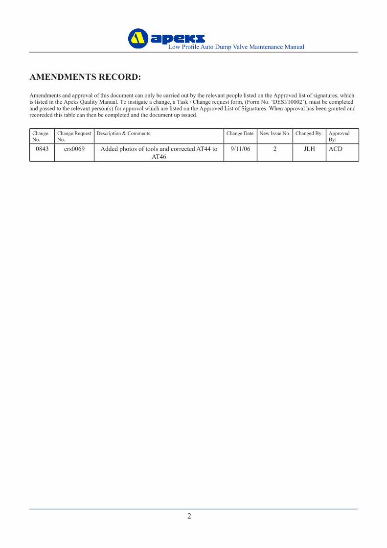
Change No.
Change Request No.
Description & Comments: Change Date New Issue No. Changed By: Approved By:
0843 crs0069 Added photos of tools and corrected AT44 to AT46
9/11/06 2 JLH ACD
AMENDMENTS RECORD:
Amendments and approval of this document can only be carried out by the relevant people listed on the Approved list of signatures, which is listed in the Apeks Quality Manual. To instigate a change, a Task / Change request form, (Form No. ‘DESI/10002’), must be completed and passed to the relevant person(s) for approval which are listed on the Approved List of Signatures. When approval has been granted and recoreded this table can then be completed and the document up issued.

2
Low Profile Auto Dump Valve Maintenance Manual
3
Low Profile Auto Dump Valve Maintenance Manual
ContentsCOPYRIGHT NOTICE ................................................................................................................................................................ 4INTRODUCTION ........................................................................................................................................................................ 4WARNINGS, CAUTIONS & NOTES ......................................................................................................................................... 4SCHEDULED SERVICE ............................................................................................................................................................. 4GENERAL GUIDELINES ........................................................................................................................................................... 4GENERAL CONVENTIONS....................................................................................................................................................... 5DISASSEMBLY PROCEDURES ................................................................................................................................................ 5REASSEMBLY PROCEDURES.................................................................................................................................................. 7TESTING PROCEDURE ............................................................................................................................................................. 9TABLE 1 - TROUBLSHOOTING GUIDE................................................................................................................................ 10TABLE 2 - RECOMMENDED TOOL LIST...............................................................................................................................11TABLE 3 - RECOMMENDED LUBRICANTS AND CLEANERS ........................................................................................ 12CLEANING AND LUBRICATION PROCEDURE .................................................................................................................. 13TABLE 4 -TORQUE SPECIFICATIONS .................................................................................................................................. 14TABLE 5 - TEST BENCH SPECIFICATIONS ......................................................................................................................... 14 EXPLODED PARTS DRAWING.............................................................................................................................................. 15

4
Low Profile Auto Dump Valve Maintenance Manual
5
Low Profile Auto Dump Valve Maintenance Manual
COPYRIGHT NOTICEThis manual is copyrighted, all rights reserved. It may not, in whole or in part, be copied, photocopied, reproduced, translated, or reduced to any electronic medium or machine readable form without prior consent in writing from Apeks Marine Equipment Ltd. It may not be distributed through the internet or computer bulletin board systems without prior consent in from Apeks Marine Equipment Ltd.
©2006 Apeks Marine Equipment Ltd.
Low Profile Auto Dump Valve Maintenance Manual
(AP5921 Issue 2)
INTRODUCTIONThis manual provides factory prescribed procedures for the correct maintenance and repair of the Apeks Low Profile Auto Dump Valve. It is not intended to be used as an instructional manual for untrained personnel. The procedures outlined within this manual are to be performed only by personnel who have received factory authorised training through an Apeks Service & Repair Seminar. If you do not completely understand all of the procedures outlined in this manual, contact Apeks to speak directly with a Technical Advisor before proceeding any further.
WARNINGS, CAUTIONS & NOTESPay special attention to information provided in warnings, cautions, and notes that are accompanied by one of these symbols:
WARNINGS indicate a procedure or situation that may result in serious injury or death if instructions are not followed correctly.
CAUTIONS indicate any situation or technique that will result in potential damage to the product, or render the product unsafe if instructions are not followed correctly.
NOTES are used to emphasise important points, tips, and reminders.
SCHEDULED SERVICEIt is recommended that the Apeks Low Profile Dump Valve should be rinsed in fresh water after use, the operation of the valve should be checked annually and they should be stripped down and serviced every three years.However, If at all unsure about the correct functioning of the Apeks low profile dump valve, then it must be officially inspected immediately.
An Official Inspection consists of:1. Testing instructions see page 8.2. Checking that all parts are assembled correctly and
that no parts are loose.3. A visual inspection of the exhaust valve looking for
tears or holes and checking the general condition.
If a valve fails any of the 3 steps it should be fully serviced.
GENERAL GUIDELINES1. In order to correctly perform the procedures outlined
in this manual, it is important to follow each step exactly in the order given. Read over the entire manual to become familiar with all procedures and to learn which specialty tools and replacement parts will be required before commencing disassembly. Keep the manual open beside you for reference while performing each procedure. Do not rely on memory.
2. All service and repair should be carried out in a work area specifically set up and equipped for the task. Adequate lighting, cleanliness, and easy access to all required tools are essential for an efficient repair facility.
3. During disassembly, reusable components should be segregated and not allowed to intermix with non-reusable parts or parts from other units. Delicate parts, including inlet fittings and valve seats which contain critical sealing surfaces, must be protected and isolated from other parts to prevent damage during the cleaning procedure.
4. Use only genuine Apeks parts provided in the Low Profile Auto Dump Kit (AP0237). DO NOT attempt to substitute an Apeks part with another manufacturer’s, regardless of any similarity in shape or size.
5. Do not attempt to reuse mandatory replacement parts under any circumstances, regardless of the amount of use the product has received since it was manufactured or last serviced.
6. When reassembling, it is important to follow every torque specification prescribed in this manual, using a calibrated torque wrench. Most parts are made of plastic, and can be permanently damaged by undue stress.

4
Low Profile Auto Dump Valve Maintenance Manual
5
Low Profile Auto Dump Valve Maintenance Manual
1. Using the Apeks back nut tool (AT43) and appropriate torque wrench, remove the back nut from the valve.
Pinch MethodPress upwards on
sides of ‘O’ Ring to create a protrusion.
Grab ‘O’ Ring or insert ‘O’ Ring tool
at protrusion.
2. Remove the valve from the suit and remove the retaining ring.
3. Using the removal tool AT46 place over the threads of the valve body (11).The lugs of the tool fit underneath the cap (2). Screw the back nut onto the valve and tighten until the cap becomes displaced. Then remove the back nut and tool.
Removal of valve From The Suit.
Removal of the cap
GENERAL CONVENTIONSUnless otherwise instructed, the following terminology and techniques are assumed:1. When instructed to remove, unscrew, or loosen a
threaded part, turn the part anti-clockwise.2. When instructed to install, screw in, or tighten a
threaded part, turn the part clockwise.3. When instructed to remove an ‘O’ Ring, use the pinch
method (see figure below) if possible, or use a brass, aluminium or plastic ‘O’ Ring removal tool. Avoid using hardened steel picks, as they may damage ‘O’ Ring sealing surfaces. All ‘O’ Rings that are removed are discarded and replaced with brand new ‘O’ Rings.
4. The following acronyms are used throughout the manual: MP is Medium Pressure; HP is High Pressure; PN is Part Number.
5. Numbers in parentheses reference the key numbers on the exploded parts schematics. For example, in the statement, “...remove ‘O’ ring (4) from...”, the number 4 is the key number to the Spring Carrier ‘O’ Ring.
DISASSEMBLY PROCEDURES NOTE: Before performing any disassembly, refer
to the exploded parts drawing, which references all mandatory replacement parts. These parts should be replaced with new, and must not be reused under any circumstances - regardless of the age of the regula-tor or how much use it has received since it was last serviced.
CAUTION: Use only a plastic, brass or aluminium ‘O’ Ring removal tool (PN AT54) when removing ‘O’ Rings to prevent damage to the sealing surface. Even a small scratch across an ‘O’ Ring sealing surface could result in leakage. Once an ‘O’ Ring sealing surface has been damaged, the part must be replaced with new. DO NOT use a dental pick, or any other steel instrument.
4. Lift out the load transmitter (3).
CAUTION: To prevent damage to the valve always press down the cap and rotate the back nut not the valve.
CAUTION:
Align the clips with the lugs on the tool.

6
Low Profile Auto Dump Valve Maintenance Manual
7
Low Profile Auto Dump Valve Maintenance Manual
6. Remove the spring (5).
7. Remove the spring carrier (8).
9. Remove the valve seating (10).
5. Place a flat ended screwdriver in one of the four recesses around the edge and gently displace the inner cap (6) from the body (13). You may need to use one of the other recesses to remove the inner cap.
NOTE: If there is no sign of deterioration the exhaust valve does not need to be removed.
8. Carefully remove the valve (9) ensuring no damage occurs to the sealing edge.
10. Remove spring washer (11).
11. Gently lift the exhaust valve (12) and inspect the sealing edge of the exhaust and the sealing face inside the valve body.
This Ends Disassembly
Before starting reassembly, perform parts cleaning and lubrication according to the procedures outlined in ‘Cleaning & Lubrication’ on page 12.
NOTE: The adjuster (4) and clip (7) has no need to be removed as long as it rotates freely.
WARNING: Do not use a sharp implement, if the body or non return valve are damaged the valve will leak.
NOTE: Place the valve on a clean piece of sponge, this will prevent other components coming into contact and damaging the sealing edge.

6
Low Profile Auto Dump Valve Maintenance Manual
7
Low Profile Auto Dump Valve Maintenance Manual
REASSEMBLY PROCEDURES4. Place the valve (9) over the valve seating (10), sealing
edge face down.
5. Fit the spring carrier (8) ensuring the small indent on
the back locates with the raised pip on the inside of the valve (9).
6. Place the spring (5) onto the spring carrier (8) ensuring that it locates around the raised centre.
NOTE: If there is no sign of deterioration the exhaust valve does not need to be removed. In the event of the exhaust valve having been removed, the stalk of the replacement must be trimmed off.
3. Fit the valve seating (10) over the spring washer (11), this must lie flat and straight on the spring washer.
The sealing edge of the valve is critical this should be checked for damage by running a finger gently around the edge.
CAUTION:
CAUTION:If the adjusting screw and clip have previously been removed from the inner cap, the adjuster clip must be refitted chamfer outermost.
7. The stop on the inner cap and the body must be aligned as shown below in green. Push the inner cap (6) into place ensuring all clips are located correctly in the body (13).
2. Fit the spring washer (11) into the recess of the body (13) so the washer tapers upwards towards the middle.
CAUTION:The stop on the inner cap and the body must be aligned as shown above. Ensure the clips on the inner cap are inserted fully into the slots in the body. Check for any distortion of the valve body. This distortion could cause the valve to leak.
1. Pull the exhaust valve (12) tail through the valve body (13) Trim off the excess.

8
Low Profile Auto Dump Valve Maintenance Manual
9
Low Profile Auto Dump Valve Maintenance Manual
9. Line up the stop on the cap (2) to the left of the stop on the body (13) Press the cap down with palm of the hand to clip into place. Rotate the cap approx 350° to ensure the assembly is correct.
8. Fit the load transmitter (3) through the inner cap (6), this will centralise the valve. Grease the two ratchet pips as shown below by the green arrow.
CAUTION: Before fitting the cap (2), the adjuster (4) in the inner cap (6) must be fully wound down.
10. If a new decal (1) is to be fitted, the cap (2) must be degreased first.
This Ends Reassembly
11. Refit the valve to the suit using a torque wrench and a back nut tool (AT43). The valve should be torqued to 4lbs/ft or 5.4Nm.
To prevent damage to the valve always press down the cap and rotate the back nut not the valve.
CAUTION:
CAUTION: If the cap and body are not aligned correctly the cap will not rotate a full 350°.
NOTE: Older versions of the Low Profile Auto Dump Valve.Valves with a serial number previous to 308 089022 will not incorporate the alignment stops as detailed in steps 7 and 9. These alignment instructions should be disregarded.

8
Low Profile Auto Dump Valve Maintenance Manual
9
Low Profile Auto Dump Valve Maintenance Manual
3. Fit the valve to the suit following the re-assembly procedure. Seal off the cuff and submerge the shoulder of the suit, inspect the inside of the suit for any sign of water ingress.
Testing Procedures
1. This test should be carried out before the valve is fitted to the suit; Adjust the cap until it is fully open. Blow through the valve from the threaded end. There should be virtually no resistance. Rotate the cap fully closed and blow through the valve, the resistance should now be quite high.
NOTE: The valve will never fully shut off, it will always open with enough pressure applied.
2. Check the cap rotates approx 350°.

10
Low Profile Auto Dump Valve Maintenance Manual
11
Low Profile Auto Dump Valve Maintenance Manual
Table 1 - Troubleshooting Guide
SYMPTOM POSSIBLE CAUSE TREATMENT
Valve Leaks
1. Exhaust valve (12) damaged or worn. 1. Replace exhaust valve.
2. Valve Seating (10) damaged or worn. 2. Replace valve seating.
3. Sealing edge of valve (9) damaged. 3. Replace valve.
4.Inner cap (6) not clipped in correctly. 4. Re-assemble inner cap.
5. Dirt /salt deposits present on exhaust valve /valve seating.
5. Clean or replace exhaust valve or valve seating.
Valve does not operate correctly
1. Cap (2) does not turn approx 350°.
1. Check cap assembly procedures have been followed correctly. Check the inner cap and valve cap have been aligned properly.
2. Cap (2) does not turn approx 350°. 2. Check inner cap thread is intact.
3. Older valves could have a damaged Adjuster (4).
3. Replace Inner Cap (6) and Ad-juster (4).
Leakage into suit
1. The valve has not been tightened in the suit properly. 1. Re-tighten the valve.
2. An incompatible backing patch has been fitted to the suit.
2. Fit an Apeks backing patch AP0166.
3. There is no backing patch fitted. 3. Fit an Apeks backing patch AP0166.
4. Dirt/salt deposits present internally. 4. Clean the valve.
5. The valve leaks. 5. See page 8 for test specification.
Restricted air flow
1. Internal spring (5) distorted. 1. Change spring.
2. Wrong back nut fitted. 2. Fit correct back nut AP1572 & AP1573.
3. Restrictions from undersuit. 3. Ensure undersuit allows gas to vent out of the valve.

10
Low Profile Auto Dump Valve Maintenance Manual
11
Low Profile Auto Dump Valve Maintenance Manual
Table 2 - Recommended Tool List
PART NO. DESCRIPTION APPLICATIONAT43 Back Nut Tool Removal of back Nut.
AT46 Cap Removal Tool Cap Removal.
5-6mm Flat Ended Screwdriver Removal of Inner Cap.
n/a Torque Wrench Removal and fitting of valve to suit.
Notes: 1. Photos not to scale.2. Actual tools may differ from photos.AT46AT43

12
Low Profile Auto Dump Valve Maintenance Manual
13
Low Profile Auto Dump Valve Maintenance Manual
Table 3 - Recommended Lubricants & Cleaners
LUBRICANT / CLEANER APPLICATION SOURCE
Christo-Lube® MCG-111(Lubricant)
All ‘O’ Ring seals Apeks Marine Equipment LtdPN AP1495, or
Lubrication Technologies310 Morton StreetJackson, OH 45640, USA(800) 477-8704
Biox(Cleaning agent)
Biological immersion fluid for reus-able stainless steel and brass parts.
Solent Divers Ltd122-128 Lake Rd, Portsmouth,Hants, PO1 4HH
White distilled vinegar (100 gr.)(Cleaning agent)
Acid bath for reusable stainless steel and brass parts.
“Household” grade
Liquid dishwashing detergent diluted with warm water(Cleaning agent)
Degreaser for brass and stainless steel parts; general cleaning solu-tion for plastic and rubber
“Household” grade
CAUTION: Silicone rubber requires no lubrication or preservative treatment. DO NOT apply grease or spray to silicone rubber parts (eg. Diaphragm, Exhaust Valves.) Doing so may cause a chemical breakdown and premature deterioration of the material.
CAUTION: Do not use muriatic acid for the cleaning of any parts. Even if strongly diluted, muriatic acid can harm chrome plating and may leave a residue that is harmful to ‘O’ Ring seals and other parts

12
Low Profile Auto Dump Valve Maintenance Manual
13
Low Profile Auto Dump Valve Maintenance Manual
Cleaning & Lubrication Procedure
General Cleaning of all Parts1. Place all components in an ultrasonic cleaning bath containing an appropriate cleaning solution, such as Biox.2. The components should be cleaned for 6 minutes, depending upon their condition. Longer cleaning times may used if
required.3. Rinse the components in warm fresh water.4. The components should then be blown dry or left to dry naturally.
Lubrication and DressingAll ‘O’ Rings should be lubricated with Christo-Lube® MCG-111. Dress the ‘O’ Rings with a very light film of grease, and remove any visible excess by running the ‘O’ Ring between thumb and forefinger. Avoid applying excessive amounts of Christo-Lube grease, as this will attract particulate matter that may cause damage to the ‘O’ Ring.
NitroxWhen it comes to issues of nitrox safety and compatibility, the concerns lie primarily with the first stage as it is subjected to high inlet pressures. High inlet pressures lead to adiabatic compression or heating of the gas. As they leave the factory, standard Apeks regulators are suitable for use with oxygen enriched gases (i.e. nitrox, etc.) providing the oxygen content does NOT EXCEED 40% (EAN40).Any Apeks regulator, when properly cleaned, lubricated and assembled, is authorised for use with enriched air nitrox (EAN) up to 100% (EAN100). It is authorised because it has undergone adiabatic compression testing and the authorised service kit com-ponents and lubricants are compatible in elevated oxygen environments. During cleaning, a mild detergent is used to remove condensed hydrocarbons (compressor oils) from the inside passageways of the first stage. For the first stage to remain EAN100 compatible, only use hyperfiltered compressed gas (hydrocarbons < 0.1 mg/m3). Ordinary compressed breathing air to BS EN 12021:1999 does not meet this criteria. Once ordinary breathing air is used, the first stage is no longer EAN100 compatible until it is cleaned and serviced again.Although regulator second stage components are not exposed to high pressure EAN, Apeks recommends that the same cleaning procedures be followed for the complete regulator. This prevents the possibility of cross contamination and guarantees the cleanliness of the entire regulator.
WARNING: Please check the regulations regarding Nitrox in your particular country as this may differ from Apeks standard policy.

14
Low Profile Auto Dump Valve Maintenance Manual
15
Low Profile Auto Dump Valve Maintenance Manual
Table 5 - Test Bench Specifications
TEST ACCEPTABLE RANGE
Leak Test No Leaks permitted
Minimum relief pressure 0.5 to 1 mbar
Maximum relief pressure 23 to 25 mbar
Table 4 - Torque Specifications
PART NUMBER DESCRIPTION / KEY NUMBER TORQUE
AP1572,AP1573 Extended Back Plate, Back Nut. 4lbs/ft (5.4Nm)

14
Low Profile Auto Dump Valve Maintenance Manual
15
Low Profile Auto Dump Valve Maintenance Manual
1 AP5015 Decal 9 AP7049 Valve2 AP7044 Cap 10 AP7048* Valve seating3 AP7045 Load Transmitter 11 AP7043 Spring washer4 AP7046 Adjuster 12 AP7051 Non return valve5 AP7052 Spring 13 AP7041 Valve body6 AP7042 Inner cap 14 AP7053 Retaining ring7 AP7047 Adjuster clip 15 AP1573 Back nut8 AP7050 Spring Carrier 16 AP1572 Extended back plate
Low Profile Auto Dump Valve Exploded Parts Diaghram
* All marked items must be replaced when serviced.

16
Low Profile Auto Dump Valve Maintenance Manual
Notes

16
Low Profile Auto Dump Valve Maintenance Manual
LOW PROFILE AUTO DUMP VALVE
AUTHORISED TECHNICIANS
Apeks Marine Equpment LtdNeptune Way, Blackburn, Lancs, England, BB1 2BT
MAINTENANCE MANUAL
FOR
TECHNICAL SUPPORT