
Low PAH Improved Fish Smoking Stove Design Development report,€¦ · · 2017-07-19Low PAH...
46
SUSTAINABLE FISHERIES MANAGEMENT PROJECT (SFMP) Low PAH Improved Fish Smoking Stove Design Development Report SEPTEMBER 2016
Transcript of Low PAH Improved Fish Smoking Stove Design Development report,€¦ · · 2017-07-19Low PAH...

SUSTAINABLE FISHERIES MANAGEMENT PROJECT (SFMP)
Low PAH Improved Fish Smoking Stove Design Development Report
SEPTEMBER 2016

i
This publication is available electronically in the following locations:
The Coastal Resources Center
http://www.crc.uri.edu/projects_page/ghanasfmp/
Ghanalinks.org
https://ghanalinks.org/elibrary search term: SFMP
USAID Development Clearing House
https://dec.usaid.gov/dec/content/search.aspx search term: Ghana SFMP
For more information on the Ghana Sustainable Fisheries Management Project, contact:
USAID/Ghana Sustainable Fisheries Management Project
Coastal Resources Center
Graduate School of Oceanography
University of Rhode Island
220 South Ferry Rd.
Narragansett, RI 02882 USA
Tel: 401-874-6224 Fax: 401-874-6920 Email: [email protected]
Citation: Pemberton-Pigott, C., Robinson, J., Kwarteng, E., Boateng, L. (2016). Low PAH
Improved Fish Smoking Stove Design Development Report. The USAID/Ghana
Sustainable Fisheries Management Project (SFMP). Narragansett, RI: Coastal
Resources Center, Graduate School of Oceanography, University of Rhode
Island and Netherlands Development Organisation. GH2014_ACT063_SNV 46
pp.
Authority/Disclaimer:
Prepared for USAID/Ghana under Cooperative Agreement (AID-641-A-15-00001), awarded
on October 22, 2014 to the University of Rhode Island, and entitled the USAID/Ghana
Sustainable Fisheries Management Project (SFMP).
This document is made possible by the support of the American People through the United
States Agency for International Development (USAID). The views expressed and opinions
contained in this report are those of the SFMP team and are not intended as statements of
policy of either USAID or the cooperating organizations. As such, the contents of this report
are the sole responsibility of the SFMP team and do not necessarily reflect the views of
USAID or the United States Government.
Cover photo: Downdraft Fish Smoking Stove Design (Credit: SNV/C. Pemberton-Pigott)

ii
Detailed Partner Contact Information:
USAID/Ghana Sustainable Fisheries Management Project (SFMP) 10 Obodai St., Mempeasem, East Legon, Accra, Ghana
Telephone: +233 0302 542497 Fax: +233 0302 542498
Maurice Knight Chief of Party [email protected]
Kofi Agbogah Senior Fisheries Advisor [email protected]
Nii Odenkey Abbey Communications Officer [email protected]
Bakari Nyari Monitoring and Evaluation Specialist [email protected]
Brian Crawford Project Manager, CRC [email protected]
Justice Odoi USAID Administrative Officer Representative [email protected]
Kofi.Agbogah
Stephen Kankam
Hen Mpoano
38 J. Cross Cole St. Windy Ridge
Takoradi, Ghana
233 312 020 701
Andre de Jager
SNV Netherlands Development Organisation
#161, 10 Maseru Road,
E. Legon, Accra, Ghana
233 30 701 2440
Donkris Mevuta
Kyei Yamoah
Friends of the Nation
Parks and Gardens
Adiembra-Sekondi, Ghana
233 312 046 180
Peter Owusu Donkor
Spatial Solutions
#3 Third Nautical Close,
Nungua, Accra, Ghana
233 020 463 4488
Thomas Buck
SSG Advisors
182 Main Street
Burlington, VT 05401
(802) 735-1162
Victoria C. Koomson
CEWEFIA
B342 Bronyibima Estate
Elmina, Ghana
233 024 427 8377
Lydia Sasu
DAA
Darkuman Junction, Kaneshie Odokor
Highway
Accra, Ghana
233 302 315894
Gifty Asmah
Daasgift Quality Foundation
Headmaster residence, Sekondi College
Sekondi, Western Region, Ghana
233 243 326 178
For additional information on partner activities:
CRC/URI: http://www.crc.uri.edu
CEWEFIA: http://cewefia.weebly.com/
DAA: http://womenthrive.org/development-action-association-daa
Daasgift: https://www.facebook.com/pages/Daasgift-Quality-Foundation-
FNGO/135372649846101
Friends of the Nation: http://www.fonghana.org
Hen Mpoano: http://www.henmpoano.org
SNV: http://www.snvworld.org/en/countries/ghana
SSG Advisors: http://ssg-advisors.com/
Spatial Solutions: http://www.spatialsolutions.co/id1.html

iii
ACRONYMS
BaP Benzo(a)pyrene
CoP Chief of Party
CR Central Region
CSIR Council of Scientific and Industrial Research
EU European Union
FAO Food and Agricultural Organization of the United Nations
FRI Food Research Institute
FTT FAO Thiaroye Technology
GHs Ghanaian Cedi
PAH Polycyclic Aromatic Hydrocarbon
SFMP Sustainable Fisheries Management Project
SNV Netherlands Development Organization
USAID United States Agency for International Development

iv
TABLE OF CONTENTS
ACRONYMS ........................................................................................................................... iii
LIST OF FIGURES .................................................................................................................. vi
LIST OF TABLES .................................................................................................................... vi
INTRODUCTION ..................................................................................................................... 7
Context ................................................................................................................................... 7
Objectives .............................................................................................................................. 7
OVERVIEW OF FISH SMOKING ........................................................................................... 7
Smoking process .................................................................................................................... 8
Actions of smoke ................................................................................................................... 8
FISH SMOKING STOVES ....................................................................................................... 9
Chorkor .................................................................................................................................. 9
Morrison ............................................................................................................................... 10
Open Source ......................................................................................................................... 11
Divine ................................................................................................................................... 12
FTT ...................................................................................................................................... 13
Stove technology analysis .................................................................................................... 14
OPTIMAL PHYSICAL CONDITIONS IN VIEW OF REDUCING PAH IN THE FISH
SMOKING PROCESS............................................................................................................. 15
Source of PAH in the fish smoking process ........................................................................ 15
Situation in Ghana................................................................................................................ 15
Design Recommendations ................................................................................................... 16
STOVE DESIGN REVIEW .................................................................................................... 17
Analysis of Existing Designs ............................................................................................... 18
Impacts of Existing Designs ................................................................................................ 19
DESIGNING A LOW PAH IMPROVED FISH SMOKING STOVE .................................... 22
Initial Design Approach ....................................................................................................... 22
Separate the fire from the air supply, mix after combustion ................................................ 22
Control ................................................................................................................................. 23
Self regulating ...................................................................................................................... 24
Combustion quality .............................................................................................................. 24
Pre-cast cement cap on the air mixing chamber .................................................................. 26
Downdraft drying chamber .................................................................................................. 26
Gas Exit Tunnel ................................................................................................................... 27
Chimney ............................................................................................................................... 27
Maximum temperature available in the drying chamber ..................................................... 27
Materials used in construction ............................................................................................. 28

v
Preliminary Construction ..................................................................................................... 28
Second design phase ............................................................................................................ 28
Final optimisation of the design ........................................................................................... 29
TRAINING OF TRAINERS.................................................................................................... 30
LAB TEST RESULTS ............................................................................................................. 32
Test Results .......................................................................................................................... 32
Way forward ........................................................................................................................ 32
CONCLUSION ........................................................................................................................ 33
REFERENCES ........................................................................................................................ 34
ANNEX 1: DOWNDRAFT STOVE V0.5 .............................................................................. 35
New developments ............................................................................................................... 36
Size ....................................................................................................................................... 37
Combustor ............................................................................................................................ 37
ANNEX 2: MORRISON/CHORKOR RETROFIT DESIGN ................................................. 42
Observations ........................................................................................................................ 42
General approach ................................................................................................................. 43
View 1 .................................................................................................................................. 44

vi
LIST OF FIGURES
Figure 1 Chorkor stove ............................................................................................................... 9 Figure 2 Morrison stove with two work stations ...................................................................... 10 Figure 3 Open source ............................................................................................................... 11 Figure 4 Divine stove ............................................................................................................... 12 Figure 5 FAO Thiaroye Technology (FTT) ............................................................................. 13
Figure 6 Smoking fish .............................................................................................................. 20 Figure 7 Distribution of heat across the area of the tray .......................................................... 21 Figure 8 Baffle plate ................................................................................................................. 21 Figure 9 The combustion zone (1) is beneath the brick flame tunnel rising from the right hand
end. The hot exhaust gases are then mixed with air in a mixing chamber (3). ........................ 22
Figure 10 Stainless steel plate slides in a frame to open a vent into the chimney ................... 23 Figure 11 By setting the opening, the level of heating and thus the chimney draft can be
regulated ................................................................................................................................... 23
Figure 12 Air entrance .............................................................................................................. 24 Figure 13 Top of the flame tunnel and drying chamber ........................................................... 25 Figure 14 Top of the flame tunnel ............................................................................................ 25 Figure 15 Heat resistance cover at the top of the fire chamber ................................................ 26
Figure 16 Chimney ................................................................................................................... 27 Figure 17 Preliminary Construction ......................................................................................... 28
Figure 18 The fire is built upon a grate that sits on the flat floor ............................................. 29 Figure 19 Increased vertical flame tunnel ................................................................................ 29 Figure 20 Loose stacked 3D model of v 0.3 was loosely assembled ....................................... 30
Figure 21 Laying fish on trays ................................................................................................. 31
Figure 22 Construction of version 0.4 ...................................................................................... 31 Figure 23 PAH(4) By Device ................................................................................................... 32 Figure 24 Stove Version 0.4 ..................................................................................................... 35
Figure 25 Version 0.5 of stove ................................................................................................. 37 Figure 26 Construction plan for 0.5 version of stove. .............................................................. 41
Figure 27 Retrofit of Morrison/ Chorkor stoves ...................................................................... 42 Figure 28 SNV Fish Smoker – Morrison Stove Retrofit View 1 ............................................. 43
Figure 29 SNV Fish Smoker – Morrison Stove Retrofit View 2 ............................................. 43 Figure 30 Retrofit view of Morrison Stove .............................................................................. 44 Figure 31 Drawing Retrofit Combustor ................................................................................... 45
LIST OF TABLES
Table 1 Stove technology analysis ........................................................................................... 14 Table 2 Construction sequence for 0.5 version of stove .......................................................... 38

7
INTRODUCTION
Context
Across Africa various traditional methods are employed to process, preserve and store fish.
These include smoking, drying, salting, frying and fermenting and various combinations of
these treatments. The advantages of smoking fish are manifold: it prolongs shelf life,
enhances flavor, reduces waste in times of bumper catches and permits storage for the lean
season. It increases protein availability to people throughout the year and makes fish easier to
pack, transport and market. It is a major source of income for coastal-dwelling communities
and traders. In Ghana, smoking is the most widely-used method for preserving fish and is the
most common activity for women in fishing communities. Practically all fish species
available in the country can be smoked. It has been estimated that between 70 and 80 percent
of the domestic marine and freshwater fish catch is consumed in smoked form.
SNV (Netherlands Development Organisation) Ghana is committed to combating
deforestation, to increasing the profitability of agro-processing businesses in Ghana and to
improve the working environment for women entrepreneurs. Through the introduction of
energy efficient and clean cooking technologies, all these targets can be addressed. Improved
cooking stoves and dryers/smokers can significantly reduce fuelwood consumption and
reduce human exposure to heat and smoke. The Sustainable Fisheries Management Project
(SFMP) is a 5-year intervention aimed at introducing improved food processing and other
renewable energy technologies to agro-processing communities.
Recent studies by SNV have shown that improved fish smokers produce products with levels
of Polycyclic Aromatic Hydrocarbons (PAH) that are well above current recommended levels
for human health. Because there are different sets of PAH monitored for food quality
regulation, we note here for clarity that the EU uses PAH(4) and PAH(8). This means,
depending on the variable, they regulate the levels of either 4 or 8 of the most harmful
compounds in the PAH family. All are considered carcinogenic. Other jurisdictions use, or
track, PAH(7) and PAH(16).
Objectives
This study seeks to assess improved fish drying technologies and provide design guidance for
the development of an adequately efficient fuel device that produces dried fish with low PAH
levels. This report presents an overview of the fish smoking process and a review of five
smoking stoves tested by SNV: three existing low-cost stove designs (Chorkor, Morrison and
Open Source), plus the two higher-cost stove designs (FAO Thiaroye Technology (FTT) and
Divine), with respect to performance, construction, costs, capacity, user-friendliness and
PAH levels in fish. Based on this analysis, the optimal conditions for this process are
recommended and a design process is outlined that resulted in two new prototype fish
smoking stoves– a new build downdraft stove and a combustor to retrofit to existing stove
types.
OVERVIEW OF FISH SMOKING
Smoking is a traditional processing technique used to preserve fish. It also gives color and a
range of tastes appreciated by consumers. It consists of exposing fish to the effects of heat
and smoke, both produced by the combustion of biomass (wood, sawdust, coconut husks,
etc).

8
Smoking process
There are two types of smoking: hot smoking and cold smoking, characterized by the
processing temperature and the temperature reached at the centre of the fish flesh.
Cold Smoking: It is practiced primarily in the North. The smoke temperature is
maintained between 20°C and 25°C and should never exceed 28°C as the fish should
neither cook nor be too dry. The length of treatment varies from a few hours to several
days, depending on the type of installation and the desired product. Cold smoking
requires strict hygienic conditions and quality control as the final product has high
water content. Its shelf life is limited and it is usually vacuum-packed and stored cold or
frozen.
Hot smoking: In this case, the fish is cooked while giving it a smoky flavor. This is the
most common practice in developing countries because it gives a relatively stable
product. The fish is usually salted and dried before smoking. The smoking temperature
varies between 60°C and 120°C. The water content of the finished product is quite
variable because it depends on the desired product and the fish species used.
Depending on the type of fish being smoked and the product presentation (species, thickness,
and way of cutting it), its ultimate use and the length of time it has to be stored. The hot
smoking process can take from 1 hour to 2 days. It is done at temperatures above 80°C which
is high enough to cook the fish:
“Soft smoking”, which usually takes about 1-2 hours, yields a moist, versatile product
with about 40-55 percent moisture content and a shortened shelf life of 1-3 days which
limits its market distribution radius.
“Hard smoking”, which is usually preceded by soft smoking, takes about 10-18 hours
depending on the weather, yielding fish with 10-15 percent moisture content. It is even
possible to bring it below 10 percent. Fish smoked by this process have a shelf life of 6-
9 months when stored properly. As a result it can be traded over a large geographic
area.
Actions of smoke
During the smoking process, smoke has different actions on the fish:
Organoleptic action: the color of smoked fish is mainly due to the Maillard reaction (hot
smoking). The longer the smoking process, the more the color of the fish will be
transformed, but it can also vary with the species of wood used. Phenols are primarily
responsible for the aroma.
Chemical Action: smoked fish using traditional techniques may undergo slight
denaturing of some proteins. The important chemical action is the effect of phenols on
fish lipids: they inhibit the propagation of auto-oxidation.
Bacteriological action: in hot smoking, it is the heat that destroys microorganisms.
Smoke may have an antiseptic role through the phenolic fraction but this action is low.
Toxic Action: the preservative functions, flavoring and coloring of the smoking process
are well correlated with the smoke intake but it is also known that the smoke carries
polycyclic aromatic hydrocarbons (PAHs), known for decades as carcinogenic in
humans. Today, smoking processes are under surveillance of the authorities as the
European Union (EU) applies a new health standard to smoked products. Per EU
standard, level of PAH(4) in smoked fish products should be ≤ 12 mg/kg and that of
Benzo(a)pyrene (CR) should be ≤ 2 mg/kg.

9
FISH SMOKING STOVES
The five fish smoking stoves tested by SNV in Ghana are described below based on data
provided by SNV and from the literature.
Chorkor
Named after a small fishing hamlet on the outskirts of Accra, the Chorkor stove was
developed and introduced in 1969 by the UN Food and Agriculture Organization (FAO) and
the Food Research Institute (FRI) of the Council of Scientific and Industrial Research (CSIR)
in Ghana. See Figure 1.
Figure 1 Chorkor stove
The Chorkor is composed of a square combustion chamber with one hole in front. It can be
constructed in single or double units. Wooden trays (~8 per unit but can be more in peak
season) are loaded on top of the combustion chamber. Heat and smoke generated in the
combustion chamber rise through the wooden trays, drying and smoking the load of fish in a
single stage process. Compared with traditional smoking stoves, the main improvements of
the Chorkor stove include a greater heat retention in the structure, a larger smoking capacity
and in consequence, reduced fuel consumption and a shorter smoking time.
Constructed with locally available materials: clay and clay bricks, plastered clay bricks (fired
or not), the cost of construction is low, around 400-800 GHs depending on labour, numbe of
trays etc.
Since its introduction, the Chorkor stove became popular in Ghana and in most western,
central and eastern African countries for the following reasons:
Low construction costs and long life (4 to 8 years depending on construction materials)
Large capacity (up to 18 Kg of fish per tray, with 16 trays per double unit)
High quality and uniformity of product, reduced smoking time
Ease of operation: less time and effort required
Lower fuel consumption than traditional processes
The advantages of the Chorkor should however be considered as relative to previous,
inefficient smoking technologies. Indeed, fuel consumption of the Chorkor is still high. In

10
addition, the stacking order of the trays has to be changed during the process. This is
laborious as all trays have to be removed. Also, the working environment is smoky as there
are gaps between trays and there is no chimney to carry the smoke away. Last and certainly
not least, levels of PAH in the end product are higher than the traditional method and
according to SNV tests, well above EU regulation limits: 11 times BaP limit and 7 times
PAH(4) limit.
The increase in PAH levels can be explained by the greater confinement of the smoke witinh
the Chorkor, the increased concentrations of pollutants from the smoke and the higher
processing temperatures.
Morrison
The Morrison stove is a product of Morrison Energy Limited, a private Ghanaian enterprise
that aims at improving the fish smoking industry with new processing technologies that are
more energy efficient and more user friendly. In 2009, Morrison Energy Limited proposed
some improvements to address the high fuel consumption and various smoking problems
associated with the Chorkor stove. See Figure 2.
Figure 2 Morrison stove with two work stations
The design of the Morrison stove is very similar to the Chorkor stove detailed above. With a
simple combustion chamber having the same characteristics, albeit with additives to the clay
mix to improve thermal performance, the main differences are the interlocking tray frame and
the addition of short a chimney on top. The interlocking frames carrying the fish are designed
such that they overlap preventing the loss of heat and smoke, a noticeable problem with the
Chorkor stove. Lastly, the Morrison stove is built with a 24cm high chimney cover attached.
This device prevents the heat and smoke from spreading into the room, enhancing the drying
and smoking function.

11
The Morrison stove can be built using similar materials as the Chorkor stove: clay mud, clay-
mud blocks sun-dried or baked with clay-mud mortar, wood planks, and or softwood.
However, due to additional work on tray construction, new material for the chimney as well
as a margin for Morrison Energy Limited, its price is 1200 - 2000 GHs, depending on the
materials used.
According to preliminary energy assessments conducted by SNV Ghana, the Morrison stove
is 38% more fuel efficient than the Chorkor stove, using 0.38 kg fuel wood per kg smoked
fish, while the Chorkor stove uses 0.62 kg fuel wood per kg smoked fish.
The Morrison stove therefore reduces fuel consumption and smoke emitted around the stove
during the smoking process which were the main objectives of its development. However,
some constraints remain such as the difficulty of arranging the positions of trays during the
process, made even more difficult by the top chimney. The confinement of heat and smoke
does reducing fuel consumption but the combustion itself was not improved. In addition,
levels of PAH in the end product are higher, 15 times BaP limit and 9 times PAH(4) limit
based on SNV tests. The earlier assumption that the higher levels of PAH between the
Chorkor and the barrel are due to the greater smoke confinement seems to be confirmed as
levels of PAH with the Morrison are higher than with the Chorkor and the main difference
between the two is the greater smoke confinement.
Open Source
After supporting various private stove building entrepreneurs in technology development,
SNV Ghana adopted a different approach to reach a larger impact: an open source model. A
workshop was organized by SNV in May 2015 to introduce the open source stove
technology. See Figure 3.
Figure 3 Open source
From the outside, the Open Source stove is similar to the Chorkor and Morrison stoves. The
main difference is the design of its combustion chamber, based on the up-draft principle. The

12
stove is also insulated with a mixture of clay, wood ash and sawdust between the combustion
chamber and the stove body brick walls. A metal sheet with perforated holes is fixed on the
top of the combustion chamber as a buffer to avoid direct flame to the fish. Above the
perforated metal sheet, the combustion chamber is widening in a conical shape to the size of
the fish smoking tray. The trays are stacked one on top of another and at the top a hood and
short chimney are isntalled.
According to preliminary energy assessments conducted by SNV Ghana, the burnt brick
Open Source stove shows about 26% fuel saving over the Morrison stove. This improvement
is mainly due to the design of the combustion chamber, with is smaller and insulated.
No data on levels of PAH in the end product from the Open Source stove are available yet but
it is likely that levels in the end products will be higher than EU regulation limits due to the
similarity in design to the Morrison and Chorkor stoves.
Divine
The stove was developed in 2004 by Benvic Food Processing and Training Company due to
the rising cost of fuel for smoking and the not-user-friendly nature of the existing stove
(excessive smoke and heat generated during smoking). See Figure 4.
Figure 4 Divine stove
The Divine stove consists of two main components, the smoking chamber and the burner. It
is a metallic stove made of aluminum and stainless steel. The smoking chamber is a square-

13
shaped metal box and consists of two sections, one for drying and one for smoking. The
inside of the smoking chamber is partitioned into six parts; the bottom three partitions are
mainly used for drying (cooking) while the remaining top three partitions are used for
smoking.
The burner consists of a steel cylinder. It is filled with sawdust or rice husk by the help of a
PVC pipe that fits in a 5cm hole at the bottom and between three-legged stands at the top.
Once the fuel is compressed, the PVC pipe is removed creating an internal combustion
chamber. Approximately 5kg of saw dust are needed to fill one cylinder which will burn 5
hours.
The Divine stove is mainly built with stainless steel and aluminum, relatively expensive
materials. The current price of constructing one Divine stove is around 3800 GHs.
Comparing the energy consumption of the Divine stove with that of the Chorkor, the
efficiency improvement of the Divine stove is about 32%.
In terms of PAH levels, the Divine stove is significantly better than the Chorkor and the
Morrison stoves. Tests were performed on 3 different kind of fish (sardinella, barracuda and
tuna) and levels of PAH were below EU regulation limits for tuna only, which is not oily
compared to the 2 other species. The Divine stove has therefore some potential but still
requires further technical improvements to meet the EU set standards for all smoked
products.
FTT
The FAO Thiaroye Technology (FTT) is a technique drawn from the collaborative efforts
between the FAO and the CNFTPA training institute in Senegal. It was recently introduced to
Ghana by the FAO and SNV IFS project. (See Figure 5)
Figure 5 FAO Thiaroye Technology (FTT)
The stove uses a two chamber process with drying conducted on one side fired by charcoal
and smoking on the other side utilizing a separate fuel source for smoke generation. Because
the first chamber charcoal uses a low PAH emitting fuel the result is good. Between the
chamber and the furnace, a metal tray prevents fish oils from falling on to the charcoal fire,
which again reduces the generation of PAH. The chamber has a hot air distributor composed
of two metal boxes. This system improves the vertical distribution of hot air in the tray and
reduces the frequency of interchanging the trays. Once the process is complete, racks loaded

14
with cooked fish are transferred from the cooking compartment to the smoking one. The
second compartment of the kiln is used for the indirect smoking. It is connected to a smoke
generator with a smoke filter in between. A sponge of plant origins (loofah), moistened with
water is used to purify and cool down smoke from the smoke generator. The fuel of the
smoke generator, coconut fibre, is also humidified at 16-20% to avoid flames from forming.
Smoking is performed during an hour at a temperature between 30 and 34 °C.
Because of the different metallic parts made of galvanized steel, required for this stove, its
construction cost is quite high, around 5600 GHs.
The main advantage of this technology is the very low levels of PAH contamination that are
below the EU export limit. This is achieved by the use of two different chambers for cooking
and smoking, the prevention of oils dripping on the fuel during cooking and the use of a low
PAH emitting fuel, charcoal, for the cooking phase.
This stove also presents opportunities for additional revenue for fish operators, with the
possibility to process by-products. Fat gathered through the fat collection tray allows, for
example, the manufacturing of soap or can be used as cooking or frying oil.
Stove technology analysis
Based on the data provided by SNV and data available from the literature, the following chart
presents a summary of the stoves’ specifics12
.
Table 1 Stove technology analysis
Stove Performance
Const
ruct
ion
mat
eria
ls
Cost
(G
Hs)
Cap
acit
y (
fres
h
fish
)
User-friendliness PAH levels
in fish
Chork
or
- Baseline stove
- High fuel consumption
- 0.62 kg fuel wood per kg smoked
fish (soft smoking)
- 25.43 MJ/kg smoked fish (soft
smoking)
Clay
mud,
wood
400-
800
300
kg
- Easy to use
- Smoky and hot
working
environment
- Tray arrangement
difficult
High
11 times EU
BaP limit
7 times EU
PAH4 limit
Morri
son
- Improved mainly due to greater
smoke confinement
- 33% more efficient than the
Chorkor stove (soft smoking)
- 0.38 kg fuel wood per kg smoked
fish (soft smoking)
- 1.41 fuel wood per kg smoked
fish (hard smoking)
Clay
mud,
wood,
metal
1200 300
kg
- Less smoke
- Tray arrangement
more difficult due
to the top chimney
High
15 times EU
BaP limit
9 times EU
PAH4 limit
1 No information was available on smoked fish quality: Chorkor, Morrison and Open Source stoves are more
likely to produce quite dark smoked fish due to the use of wood first and the simultaneous conduction of the
cooking and smoking phases.
2 Performance data are to be used with precaution: results were obtained from different tests, done with different
fish species and not following the same cooking process (soft vs. hard smoking). Tests were also not conducted
at full capacity, more likely leading to higher specific fuel consumptions.

15
Stove Performance
Const
ruct
ion
mat
eria
ls
Cost
(G
Hs)
Cap
acit
y (
fres
h
fish
)
User-friendliness PAH levels
in fish
Open
Sourc
e
- Combustion efficiency improved
- 25.5% more efficient than the
Morrison (soft smoking)
- 1.05 fuel wood per kg smoked
fish (hard smoking)
Bricks
,
metal,
wood
300
kg
- Less smoke
- Tray arrangement
more difficult due
to the top chimney
N/A ( likely
similar to
Chorkor and
Morrison
stoves)
Divin
e
- Use sawdust as fuel
- 32% more efficient than the
Chorkor stove (hard smoking)
- 17.34 MJ/kg smoked fish (soft
smoking)
Alumi
num
and
stainle
ss
steel
3800 N/A - Smoke-free
working
environment
- Tray arrangement
difficult due to heat
- More care and
maintenance
needed
Below EU
limits for
some fish
such as tuna,
above for
other oily fish
species
FTT - Improved process with separate
cooking and smoking phases
- 33% more efficient than the
Chorkor stove (hard smoking)
Bricks
,
galvan
ized
steel,
wood
5600 200
kg
- Smoke-free
working
environment
- More care and
maintenance
needed
Below EU
limits
OPTIMAL PHYSICAL CONDITIONS IN VIEW OF REDUCING PAH IN THE FISH SMOKING PROCESS
Source of PAH in the fish smoking process
The amount of PAHs formed during the processing of fish depends mostly on the conditions
of smoking. In traditional smoking, smoke is generated at the bottom of an oven and the fish
is placed directly over the smoking wood. In these conditions, PAHs are mainly produced by
the following:
incomplete combustion of wood: generation of wood smoke during curing is a typical
example of incomplete combustion, and above 400°C PAHs are generated and released
into the various smoked products
oil pyrolysis: the formation of PAHs is known to occur through pyrolysis of oil at
temperatures above 200°C and it is highly stimulated at temperatures over 700°C. When
the fish is placed over the wood, oil drops in direct contact with the flame, generating
PAHs that become deposited back on the fish
In some case, PAHs can already be present in fresh fish due to natural (forest fires) and
human activities (anthropogenic sources) around the water. PAHs are lipophilic in nature and
usually accumulate in the fatty tissues of organisms. These levels might not be detected in the
fresh fish due to low concentrations but during the drying process heat will burn down the fat
deposits causing some of the PAHs to escape and to be deposited on the fish.
Situation in Ghana
In Ghana, the smoking of fish using traditional kilns is generally carried out with wood at
temperatures of 300°C to 700°C. With basic combustion technologies and incomplete
combustion due to the need to produce smoke, significant amounts of PAHs are produced. In
most cases cooking and smoking phases are performed in the same chamber at the same time,

16
therefore exposing the fish to PAHs over a long time, especially for the hot smoking process.
There are examples of operators drying with a clean(er) fire then smoking afterwards with,
for example, coconut husks which produce copious amounts of smoke. Critically, since little
to nothing is done to prevent oil from dropping directly in the fire or immediately next to it,
additional amounts of PAHs are generated by the fire and these pass into the gas stream.
For all the above reasons, levels of PAHs in smoked fish produced by the Chorkor, the
Morrison and more likely the Open Source stoves are high and well above the regulated EU
limits. Efficiency improvements such as a greater smoke confinement can even increase
levels of PAHs in the end product. The main issues with the barrel, the Chorkor and the
Morrison stoves are:
poor control of the fire power resulting in high temperatures well above optimum
in many cases cooking and smoking phases are concurrent
in those models, nothing preventing oil from dropping on the fire
the deflector plate in the Open Source model is intended to distribute the hot gases more
evenly across the tray area. This has the effect of collecting the falling oil drops and
providing a roasting surface heated by the fire and the PAH rises into the fish above.
The Divine stove has some potential in producing smoked fish with PAHs levels below EU
regulation limits. However, more research should be conducted as tests show that this was
only achieved with one fish species, the barracuda – a low fat fish. As oil cannot drop in to
the fire, it may be that the detectable PAH was formed within the fish by the high processing
temperature rather than deposited from the smoke. If correct, this would explain why higher
fat fish species yield higher PAHs levels.
At present, only the FTT stove produces smoked fish with levels of PAHs below EU
regulation limits. This is achieved in part by using separate cooking and smoking phases, the
elimination of oil dropping on fire and the use of a low PAHs emitting fuel during the
cooking phase followed by a low temperature smoke generator in the smoking phase.
Design Recommendations
In order to reduce PAHs levels in smoked fish to a level nearer to EU standard No 835/2011,
the following recommendations are made:
Cooking and smoking phases should be done separately: the separation of the two
phases presents the advantage of cooking first without or with very low levels of PAHs,
then smoking during a reduced duration.
Where this is not practical or affordable the drying should be done with a clean burning
fuel+combustor combination, followed by smoking using either a second fire chamber
or in a manner which offers effective control over the combustion conditions.
Indirect cooking or direct cooking with low PAHs concentration: If the drying and
smoking phases are separated, no smoke is applied during the drying phase. Ideally,
drying should be done indirectly, with fish placed in a chamber heated from the outside.
This presents the advantage of not requiring a very clean combustion because there is
no contact between smoke and fish. It is however, more expensive to implement and is
likely to affect the taste. Direct cooking can be done but with heat from a clean
combustion or, as temperature should not be too high, with any smoke diluted with
clean air.
Moderate cooking temperature: a temperature of 80°C is enough to cook the fish.
Ideally, it should not be over 85°C in order to mitigate against high temperature fat-
burning and the direct formation of PAHs in the fish. Depending on the fish species and

17
the quality of the end-product sought (‘soft’ or ‘hard’ smoked), the drying time can be
adjusted but do not raise the drying temperature.
Completely avoid dropping fish oil onto the fire: In order to prevent oil pyrolysis and
the generation of PAHs, a mechanism should be created either to collect the oil and
remove it without being heated, or the heat should be generated on the side and not
directly below the dripping fish.
Low gas temperature for the smoking phase: Separating the drying and smoking phases
will reduce PAH formation and deposition as the smoking duration will be shortened.
Having limited the formation of PAH inside the flesh during the drying phase, the
deposition of PAH on the surface automatically limits the level inside. The EU tests the
level in the whole flesh, not only the surface. It is possible to reduce the PAH
formatting within the flesh even further by cooling the smoke to a temperature of about
30°C, by using a water bath for example.
Taste: It is not known how much of the taste is provided by the drying temperature, the
‘cooking’ of the fish and or the deposition of the smoke, and even the level of
deposition. In some regions of Africa the fish is expected to have a slightly crispy
exterior produced during a brief ‘roasting’ in the dryer. Until the factors affecting taste
can be clearly defined, the system should be as controllable and as flexible as possible
within budget limitations.
By implementing these recommendations, it is possible to produce smoked fish with very low
levels of PAHs, much lower than are presently being detected and even lower than the current
EU requirements. The FTT stove is a good example. Other research and development can be
referenced:
Collaboration between CIRAD in France and LFCIA in Senegal: through the
implementation of a step of dehydration/curing without smoke followed by a smoking
phase, the level of Benzo(a)pyrène in the smoked fish was below 1 ppb and total HAPs
were below 5 ppb.
IRT in Gabon: development of a smoking stove with separated cooking and smoking
phases, indirect cooking and direct smoking with cooled smoke.
STOVE DESIGN REVIEW
The ancient practise of fish smoking has received attention from numerous development
initiatives seeking to improve the capacity, working conditions, quality and fuel efficiency of
this widespread industry. Smoked fish, either soft-smoked or hard-smoked, is a part of a
traditional diet. The processing allows for fish, which otherwise have a very short shelf life at
room temperature, to be sold over a much larger area beyond the coastal region. The practical
marketing radius is about 200 km from the point of origin.
It is well known that smoking foods introduces smoke particles in two forms: solid particles
that are essentially uncombusted carbon, and condensed or gaseous volatiles containing a
myriad of chemical components including polycyclic aromatic hydrocarbons (PAH). There
are several ‘sets’ of PAH’s that are monitored in the food supply, varying from one
jurisdiction to another. In the EU, the set monitored are known as PAH(4).
Testing during the contract period provided some interesting guidance on the origin of the
following:
Pyrene
Benzo(a)anthracene
Chrysene
18
Benzo(a)pyrene
Benzo(a)pyrene (BaP), is so important a toxin that it is separately tracked and its maximum
separately regulated. It seems to be largely created by heating the oil of the fish, not from the
smoke. To limit the level, the fish surface should not be heated above 100˚C or preferably,
not more than 90˚C. When the maximum air/gas temperature was kept below 105˚C, the
BaP level was extremely low (under 1 part per billion – ppb).
It appears that the other three PAHs - Pyrene, Benzo(a)anthracene and Chrysene - are largely
influenced by the content of smoke. When the fire is smoky, the levels rise, but if it is still
relatively cool, the BaP does not. Limiting the levels of all 4 requires addressing two separate
issues:
Temperature of the processing air (which includes the emissions from the fire and the
air mixed with it) has to be limited to a temperature of <105˚C. In order to do this, it is
important that there be a heat production zone, an air entry and mixing zone to cool the
gases and dry the air, and a chimney provided with sufficient heat so as to pull the air
through the trays of fish.
Limiting the generation of smoke to a low level requires that the fire be built in a
chamber which, through its inherent design features, provides a high combustion
efficiency and a temperature high enough to combust the smoke. While this may at first
seem contradictory – limiting the smoke production in a fish smoker – it is essential that
the smoke level be low throughout the drying process. Smoke can easily be added at
any stage of production, and preferably at the end so it has little opportunity to penetrate
the flesh of the fish. The construction of a low-smoke wood fire burning damp
fuelwood gathered near the sea, is not particularly challenging. It is done by using a low
level grate to elevate the charcoal produced by the fire and by combusting the smoke
and CO in a vertical brick-lined chimney. Further, the excess air level in the fire should
be low so as to prevent premature cooling of the gases (before they finish burning to
completion). This type of construction was tested and found to be highly effective at
creating a clean hot exhaust gas that was suitable for mixing into a supply of clean
ambient air.
Analysis of Existing Designs
There are two popular designs of smokers. They are functionally the same and have the
following features:
The bottom consists of a low wall with a combustion zone in which fuel is burned.
Trays of fish are loaded and set upon the wall, as many as a dozen of them.
The air which dries the fish is supplied through the fireplace. The devices differ in the
details of the fireplace, but the function is the same – a fire burning in an enclosed space
with all the air necessary for drying the product passing through the same space. This
has the effect of chilling the fire, increasing the smokiness and raising the carbon
monoxide level (CO). Higher CO means less efficient combustion.
The bottom tray is nearest to the fire and hot air, so it dries first. In order to process a
number of trays at once, it is necessary to remove the bottom tray before the others, or
else the fish starts to cook. This is inconvenient and unnecessary work. A great deal of
the time is spent when trays are being removed and re-arranged so as to get an even
processing of fish.
The trays are not very effective at keeping cool ambient air from leaking through the
gaps between trays. This leakage reduces the temperature of the processing air, and
reduces the draft pulling on the fire. This hot air draft is what moves the air through the

19
fire and then to the trays. The Morrison stove includes a cover that guides the gases into
a chimney. The chimney serves as a waste pipe and to add draft on the whole system.
To the extent it is effective, it also cools the fire creating poorer combustion conditions
because the air has to pass through the combustion zone.
There is no ‘combustor’ other than a hole in which the fuel burns on the ground. The
floor chills the fire, creating copious amounts of charcoal which cannot burn properly
during the main burn. Later, the accumulated charcoal burns out, but this energy for the
most part is not usefully applied.
In all cases, the construction of the structure of the stoves and the trays are completely
localised requiring little expertise. None of the dimensions are critical and the function
is largely unaffected by, for example, a change in height or the materials selected. More
expensive stoves are more durable because they are made using better quality materials.
The release of oils and moisture from the fish, towards the bottom of the chamber that is
often quasi-conical in shape and having a hot suface, results in the evaporation of the
liquids at high temperature, the creation of PAH chemicals and their deposition on to
the fish.
Impacts of Existing Designs
The main factors of interest in existing designs are that the smokiness of the gas stream is not
well controlled, or controllable, and that the temperatures of the gases reaching the product
are easily high enough to create unacceptable BaP levels. See Figure 6. Thus there is little
possibility of controlling the PAH(4) except by operating them with a very small fire and
taking many hours to complete the drying process. This is impractical.
Of lesser importance is the distribution of heat across the area of the tray. Poorly distributed
heat (see Figures 7 and 8) causes some fish to be cooked or even burned.
This is a resolvable problem as was demonstrated during the first field visit to a producer. By
using a baffle plate (see figure 8), or a series of baffles, the hot gases can be reasonably well
distributed across the tray area but this does not address the greater issues affecting product
quality and performance.
Placing a perforated plate over the fire chamber exit, with care to block the front edge, the
heat can be spread over the fish product resulting in two benefits: even drying and less
‘cooking’ of overheated areas .
While an attractive and inexpensive implementation, the result of food testing for PAH is not
encouraging. The PAH levels remain high because in order to complete the drying in a
reasonable time, the fire and the air/gas temperature is simply too hot under normal operating
conditions.

20
Figure 6 Smoking fish

21
Figure 7 Distribution of heat across the area of the tray
Figure 8 Baffle plate

22
DESIGNING A LOW PAH IMPROVED FISH SMOKING STOVE
Initial Design Approach
Following the PAH report by Pemberton-Pigott and Beritault (presented here in sections 1-5),
it was concluded that a completely new approach to drying fish was required that would
simultaneously address the following issues:
Overheating of the product
Evaporation of drippings causing severe contamination
Lack of meaningful control over the level of smoke applied, especially during drying
Inconvenience and drudgery swapping trays in the stack
Uneven product quality caused by uneven heating of the tray.
Separate the fire from the air supply, mix after combustion
In order to address all of these simultaneously it was decided to separate the fire and its
exhaust gases from the general air supply to the drying operation. The fire would be created
to the side of an air chamber, and air entering through a separate entrance would be mixed
with the gases prior to being applied to the product.
See Figure 9: The combustion zone (1) is beneath the brick flame tunnel rising from the right
hand end. The hot exhaust gases are then mixed with air in a mixing chamber (3).
Figure 9 The combustion zone (1) is beneath the brick flame tunnel rising from the right hand
end. The hot exhaust gases are then mixed with air in a mixing chamber (3).

23
Control
The use of a chimney is not new, but the provision of heat directly from the fire into the
chimney to maintain a minimum level of draft is novel. There is an operable vent that bleeds
hot gases into the chimney directly from the top of the flame tunnel. In this implementation, a
stainless steel plate slides in a frame to open a vent into the chimney. The hot gases entering
the lower part of the chimney create draft in the whole system. Even if the system is cold, by
heating the air in the chimney it can be made to draw air through the air path (i.e. inlet,
combustion zone, fish smoking chamber, chimney) as the hot air will rise and cause the
whole system to flow. It is akin to having an exhaust fan, but this one is powered by heat
from the fire. By setting the opening, the level of heating and thus the chimney draft can be
regulated. (Figures 10 and 11)
Figure 10 Stainless steel plate slides in a frame to open a vent into the chimney
Figure 11 By setting the opening, the level of heating and thus the chimney draft can be
regulated
24
Self regulating
The upper limit on the temperature of the mixture of exhaust gases and air can be regulated
by design, that is, the device can be made reasonably fail-safe. The draft from the chimney is
dependent on the buoyancy of the air in the chimney. By creating an appropriately sized air
entrance and sufficient mixing chamber volume, the operator of the fire finds it impossible to
over-heat the air. Even the largest fire – limited by the height and cross-section of the vertical
flame channel – cannot create a temperature above a given level because as the fire increases
in power, the amount of air drawn by the chimney also increases. Thus balancing the fire
chamber design and the air channels, the drying air can be limited in temperature. This is a
significant improvement over the traditional devices which are dependent on operator skill,
experience and guesswork about the temperature applied.
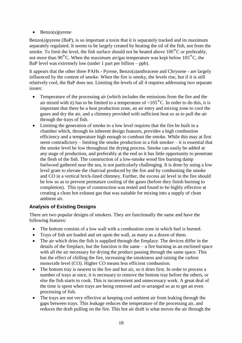
The initial design was inadequate in respect of size of the air entrance. It had to be enlarged
in subsequent models until an optimum was found. The upper limit seems to be about 120˚C
and the relative humidity is about 3%; an extremely low moisture level. This provides
excellent conditions for drying.
Figure 12 Air entrance
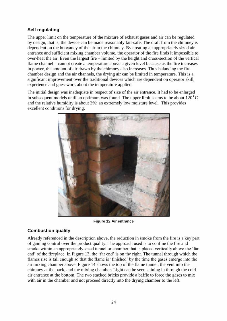
Combustion quality
Already referenced in the description above, the reduction in smoke from the fire is a key part
of gaining control over the product quality. The approach used is to confine the fire and
smoke within an appropriately sized tunnel or chamber that is placed vertically above the ‘far
end’ of the fireplace. In Figure 13, the ‘far end’ is on the right. The tunnel through which the
flames rise is tall enough so that the flame is ‘finished’ by the time the gases emerge into the
air mixing chamber above. Figure 14 shows the top of the flame tunnel, the vent into the
chimney at the back, and the mixing chamber. Light can be seen shining in through the cold
air entrance at the bottom. The two stacked bricks provide a baffle to force the gases to mix
with air in the chamber and not proceed directly into the drying chamber to the left.

25
The vent control is shown in position ‘2’ in Figure 14. It was determined during tests that the
typical position would be ‘4’. This setting provides enough heat to operate the airflow
mechanism and provide optimal drying.
Figure 13 Top of the flame tunnel and drying chamber
Figure 14 Top of the flame tunnel

26
Pre-cast cement cap on the air mixing chamber
The top of the fire chamber, which is also the top of the air mixing chamber, is capped with a
heat-resistant cover in the form of a pre-cast cement slab. (Figure 15) This material is
sufficient to deal with the temperatures experienced at the top of the chamber. The mortar
used for building with bricks is a high temperature mortar made from a mix of clay and wood
ash, and is traditionally used for high temperature stoves. It dries rapidly, has adequate
strength and is inexpensive.
Figure 15 Heat resistance cover at the top of the fire chamber
Downdraft drying chamber
The biggest change to the traditional approach is to flow the hot gas-air vertically down
through the trays rather than upwards. There are four major benefits for doing this:
Even drying: The temperature is nearly homogeneous across the whole tray because
‘hot air rises’ and if any area is slightly warmer than the rest, it rises, spreads and
equilibrates.
Much less work: The top tray gets processed first, with the result that it can be removed
when fully processed without having to disturb any of the other trays. This reduces the
physical work needed to a fraction of what is required with current models.
PAH reduction: The drippings from the fish, fall to the bottom of the chamber where it
is now the coldest, instead of the hottest. This completely removed, as far as we can tell,
any evaporation and deposition of PAH materials.
Recirculation: The hot air entering on one side (on the right as seen in the photos) can
be used to drive a circulation pattern limiting the difference in temperature between the
top and bottom trays. This homogenisation of temperature reduces the difference in
processing time between the upper and lower trays.
The term ‘downdraft’ means that the hottest air is at the top and the coolest at the bottom, and
the hot air is pulled down through the trays towards the floor by the suction of the chimney.
This cool exhaust air, laden with moisture, is conducted to the bottom of the chamber where
the updraft of the chimney removes it to atmosphere, to be continually replaced by hot dry air
within the chamber. The height of the chimney must be adequate to accomplish this, and the
heat vented directly from the fire provides the energy necessary.

27
The downdrafting flow is the result of the updraft in the chimney being sufficient to
overcome the natural tendency of the hot air in the drying chamber to rise, as well as having
additional updraft necessary to drive the flow at an adequate rate. In other words it is not
enough to have just a little more updraft, it must be able to flow the hot air through the fish
trays at a rate that accomplishes complete processing within an acceptable time, which we
were informed is 90 minutes under ideal conditions, for soft smoking.
Gas Exit Tunnel
The cooled and humid air that reaches the bottom of the chamber is conducted to the chimney
through a tunnel of brick. This must be large enough in cross-section not to be a restriction on
the flow. The entrance of the tunnel is approximately in the centre of the floor space of the
drying chamber.
Chimney
The cross-sectional area of the chimney (Figure 16)
has to be adequate to conduct the gas volume coming
from the chamber and the vented gases entering
directly from the fire. The total height is important,
however there is a practical aspect that must be
considered. The processing workshop will in most
cases have a roof over it and the chimney has to pass
through this roof. Given the climate, the needed
working space and the building materials available, the
chimney height will be at least 3.5 to 4 metres high. To
clear the roof and not have back-drafting as a result of
the relationship between the roof and the top of the
chimney it is recommended that the total height be 4.2-
4.5 metres from floor to the exit. The area of the
chimney is 700 cm2 in the brick and block section at
the bottom where the coolest air enters, and 350 cm2 in
the upper section where it moves through one or more
metal tubes. The total draft produced is applied to the
fire, via the air mixing chamber, and the air intake in a
ratio of approximately 1:6. The experiments we
conducted indicate that the upper limit of the air
temperature was about 120˚C at full flow, and that the
vent from the fire to the chimney was 50% open during
this operation.
Maximum temperature available in the drying chamber
Although it is reported above that the temperature of the heated air maximises at about
120˚C, it is possible to use a combination of controls and timing to raise the chamber
temperature higher. Once the drying chamber is heated and the exit temperature reaches 60-
80˚ it is possible to raise the temperature by closing the vent from the fire into the chimney
and driving all the hot gases into the drying chamber air supply. This reduces the draft in the
chimney and slows the entry of fresh air into the mixing chamber. The slowing of the gas
flow reduces the dilution of the hot gases with cool air. Experiments showed a terminal
temperature of about 180˚C can be achieved in this manner. There are cases when the skin of
Figure 16 Chimney

28
the fish should have a ‘toasted’ appearance. This requirement can be accommodated if this
combination of conditions can be achieved.
Materials used in construction
Every attempt was made to create a dryer that could be constructed from materials available
in most Ghanaian fishing communities. The result was the use of bricks, hollow cement
blocks, ash-clay mortar, sand-cement mortar, wood, wire mesh, nails, blockboard or cast
sand-cement slabs, steel bars and hinges. The only specialised component required is the
sheet metal vent controller that was fabricated from locally available materials.
Preliminary Construction
The first unit was constructed with advice coming from the local consultants via online
discussions, drawings and emails. The initial tests showed that the downdraft configuration
was effective and easily managed but tended to over-heat the fish. Several iterations were
tried with ever-larger air supplies until version 0.3 was showing greater promise.
V0.2 is a half-sized unit able to accommodate five trays on shelves. This was an idea arising
from the local consultants and it was evaluated as a way to eliminate having to remove
stacked trays from a pile in order to remove the bottom one. The problems with it are two-
fold: the cost is high; the stacking of trays. Figure 17 shows that more trays can fit into the
available space and when using the downdraft air flow, the top one is finished first so there is
not need to remove the lower ones.
Cost and convenience considered, there is no need to build a steel frame with tray holders.
With particular reference to the PAH(4) levels, every advantage is gained by avoiding an
updraft configuration. The steel shelves were primarily designed to avoid a problem created
by having the hot gases rise from below. Reversing the direction of flow negates the need.
Figure 17 Preliminary Construction
Second design phase
Following the rather lengthy process of getting test results from the food quality laboratory,
we had enough data to conclude that the origin of the PAH contaminants was indeed split
between overheating the fish and the deposition of smoke. The major shortfall of the

29
preliminary design was that the fire had to be kept relatively small in order to limit the
processing temperature. The problem with increasing the fire power was that it did not
increase the air flow sufficiently so as to keep the chamber temperature under 120˚C.
In version 0.3, the steel shelves were retained because they were already in the chamber. The
air entrance was increased twice in cross-sectional area and volume, providing enough data to
make a prediction as to what the ‘ultimate design’ would be like. The chimney height was
increased and the size of the combustion chamber reduced in an effort to limit the excess air
level in the flame tunnel. All of these modifications achieved the desired results.
Final optimisation of the design
Dubbed version 0.4 this unit was constructed anew and
did not make use of any of the original construction. It
was built in the centre of the building to provide room
for a much taller chimney. The draft necessary to draw in
the air through the system when the fish is cold (or
frozen in several cases) is much easier to generate by
simply using a taller chimney.The drying chamber was
constructed from less cement blocks, as was the lower
portion of the chimney. The fire chamber and the air
mixing chamber were made from bricks as before,
because of the strength and fire resistance needed. The
fire is built upon a grate that sits on the flat floor (Figure
18), with an air supply drafted through the side wall at
the ‘far end’. This air supply burns the charcoal created
Figure 18 The fire is built upon a grate that sits on the flat floor
by burning wood in a confined space. The vertical flame tunnel (Figure 19) was increased in
area to 12.5 x 12.5 cm. As a result the fire has a horizontal fuel combustion zone followed by
a vertical gas combustion zone (within the flame tunnel).
Figure 19 Increased vertical flame tunnel

30
TRAINING OF TRAINERS
This was accomplished simultaneously during the design and construction of versions 0.3 and
0.4. Instead of directing the construction of v.0.3, a loose stacked 3D model was loosely
assembled (see Figure 20). The trainers were tasked to build a copy of it using bricks and
mortar and to test it by drying a load of fish. (Figure 21) The team successfully replicated the
model using the materials available and conducted a drying test.
Figure 20 Loose stacked 3D model of v 0.3 was loosely assembled
This was followed by team discussions on the way forward: Why was the result so good?
Which result was best? What were the conditions that produced the lowest PAH(4)
contamination? How can the tray size be increased? What are the popular tray sizes in
various regions? Was it worth changing the size to accommodate the dryer, or was it better to
adapt the dryer to the existing stock of trays?
After agreeing on a way forward, version 0.4 was designed and was constructed by the
artisans using their existing skillsets.(See Figure 22) This involved wood working (trays,
doors and covers), working with cement blocks (lower sections and low temperature
portions) and brickwork. By this time they were familiar with the fire chamber construction
which was by far the most difficult part of the construction. It is assumed that during
replication in fishing communities, the all-brick fire chamber and air mixing chamber will be
constructed first by a specialist and the larger portion built by an artisan of lesser skill. The
fire and air mixing sections are working very well and can be applied to any drying task
where a large supply of hot dry air is needed. Examples of this are fruit and vegetable drying,
wood treatment, crop processing and processing of high protein foods.
The artisans demonstrated a good understanding of how the system works, and suggested
improvements to it. One valuable suggestion is that the air entrance on the right side of the
chamber should be placed about half way up the wall so as to drive a flow of air up the right
side, across the top, down on the left and under the bottom tray to return to the air entrance.

31
This can be accommodated within the design, but not within the same space. It is this idea
which holds promise to reduce the temperature differential between the top and bottom trays.
It should be implemented as a version 0.5.
Figure 21 Laying fish on trays
Figure 22 Construction of version 0.4
32
LAB TEST RESULTS
While many tests of drying at different temperatures and under different conditions were
conducted, the number of test results received was quite limited. It is not clear why this is so.
The lab has limited capacity and the turn-around time was quite lengthy. For this reason,
design decisions had to be made based on best guesses confirmed by what test information
was available. We leaned heavily on the PAH report prepared before the work started which
provided general guidance.
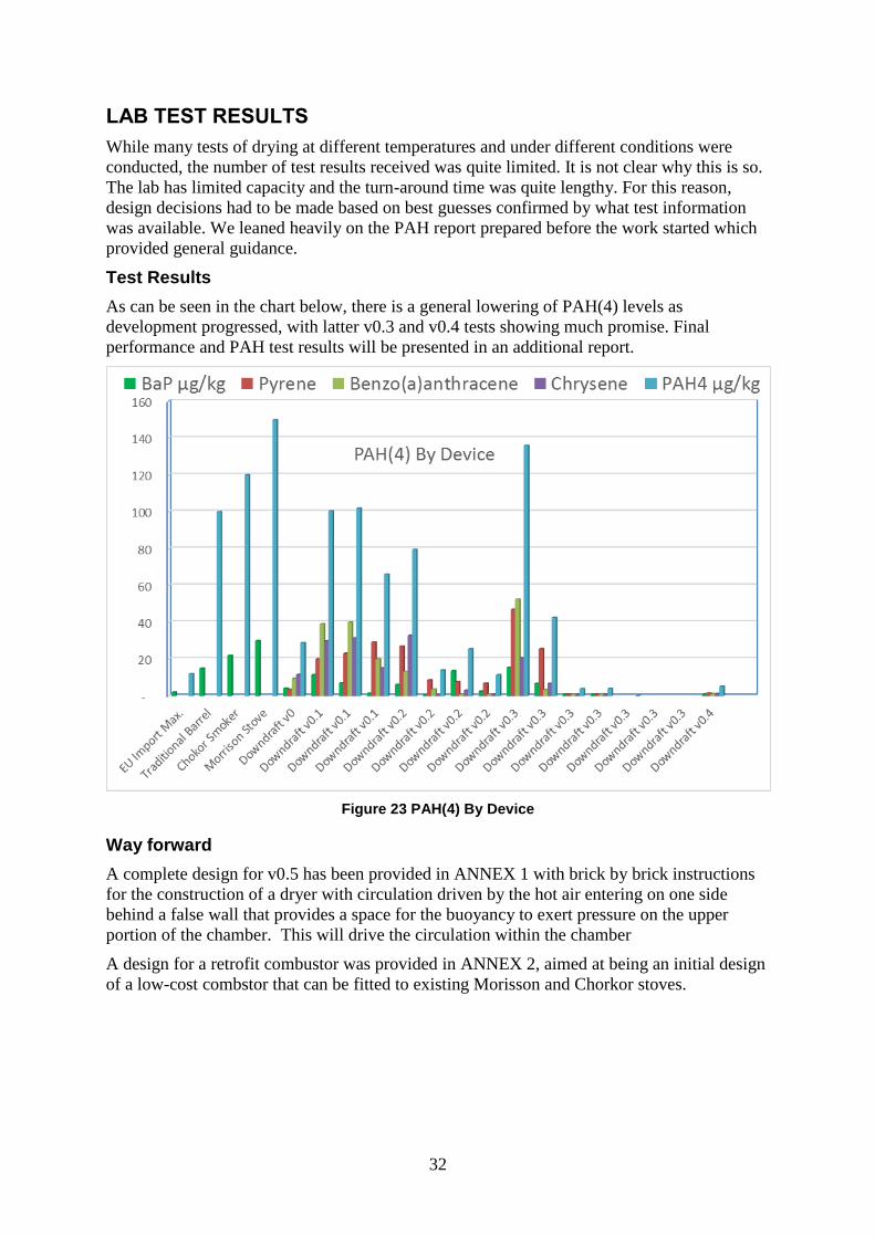
Test Results
As can be seen in the chart below, there is a general lowering of PAH(4) levels as
development progressed, with latter v0.3 and v0.4 tests showing much promise. Final
performance and PAH test results will be presented in an additional report.
Figure 23 PAH(4) By Device
Way forward
A complete design for v0.5 has been provided in ANNEX 1 with brick by brick instructions
for the construction of a dryer with circulation driven by the hot air entering on one side
behind a false wall that provides a space for the buoyancy to exert pressure on the upper
portion of the chamber. This will drive the circulation within the chamber
A design for a retrofit combustor was provided in ANNEX 2, aimed at being an initial design
of a low-cost combstor that can be fitted to existing Morisson and Chorkor stoves.

33
CONCLUSION
The smoking of fish with traditional stoves leads to high PAH levels in the end-product, well
above EU regulation limits. Most of the improved fish smoking stoves developed in the past
45 years have been designed to reduce fuel consumption and to ease operating process by
reducing smoke and heat released in to the working environment. Recent studies by SNV
have shown that some of these energy efficiency improvements produce fish with even
higher levels of PAHs, most likely due to the higher processing temperature. A newly
developed fish dryer, the FTT, produces smoked fish with very low levels of PAHs but is
however costly, thus limiting its large scale dissemination.
This report presents a review of fish smoking technologies available in Ghana and draws
recommendations on the optimal physical conditions in view of reducing PAH formation
during the fish smoking process. It is based on the guidance provided by these
recommendations that a low PAH, low cost and energy efficient fish smoking stove was
designed and constructed, which delivered promising results at the prototype stage.
As a next stage, it is recommended that limited field trials are conducted in order to gather
user-feedback and real world performance results, to then be incorporated into a second phase
of development. While the work outlined in this report has achevied some significant results,
this was conducted on a limited budget and so additional funds should be sought and
partnerships developed in order to more fully develop this promising technology.
In addition, a low-cost combustor was also designed to offer a semi-improved performance
that could be retrofitted to existing stove models. However, further development work is
needed as initial results were mixed.

34
REFERENCES
[1] FAO; Chorkor smoker, an efficient post-harvest processing technique, Africa.
[2] FAO; La technique FAO Thiaroye de Transformation (FTT), 2014.
[3] Essumang et al.; Polycyclic aromatic hydrocarbon (PAH) contamination in smoke-cured
fish products, 2012.
[4] Fall et al.; Reduction of polycyclic aromatic hydrocarbons in smoked fish arius through
process optimization; 2014.
[5] Yusuf et al.; Influence of fish smoking methods on PAH content and possible risks to
human health; 2015.
[6] Oje et al.; Levels of PAH in fresh water fish dried with different drying regimes; 2016.
[7] Olabemiwo et al.; Assessment of PAH content in smoked C. Gariepinnus and T.
guineensis fish species available in western Nigeria; 2011.
[8] Ekomi et al.; Nouveau concept de séchage et de fumage artisanal des aliments :
application en milieu de pêche artisanale au Gabon; 2013.
[9] Miculis et al.; Polycyclic Aromatic Hydrocarbons in Smoked Fish and Meat; 2011.
Documents provided by SNV Ghana:
- MANUEL FTT GHANA DEC 2014
- Final Fish Smoking Energy Audit October 6 2013
- 20150805 SFMP Stove Session Final
- An Assessment of the Efficiency and PAH of Divine Stove Draft
- SFMP Post Harvest Extension Strategy
- ENERGY AUDITS
- Factsheet PAH
- FINAL COMPOSITE REPORT - SNV IFS STOVES JULY 2015
- Final Presentation on PAH
- Fish Smoking Stoves Available Locally and Internationally
- Guide for developing and using the FAO
- OPEN SOURCE FISH SMOKING STOVE AUDIT REPORT
- Open Source Manual_IFS_Final_112015Advaced
- PAH ABU ABDALLAH
- PAH article _Silva et al.
- PAH Comparative Analysis Report FINAL
- PAHs Factsheet 2015 FINAL
- Robinson 20150806 SNV Overview SFMP Yr 2 planning workshop
35
ANNEX 1: DOWNDRAFT STOVE V0.5
Fish Smoker Version 0.5
Crispin Pemberton-Pigott
International Technical Consultant to SNV Ghana
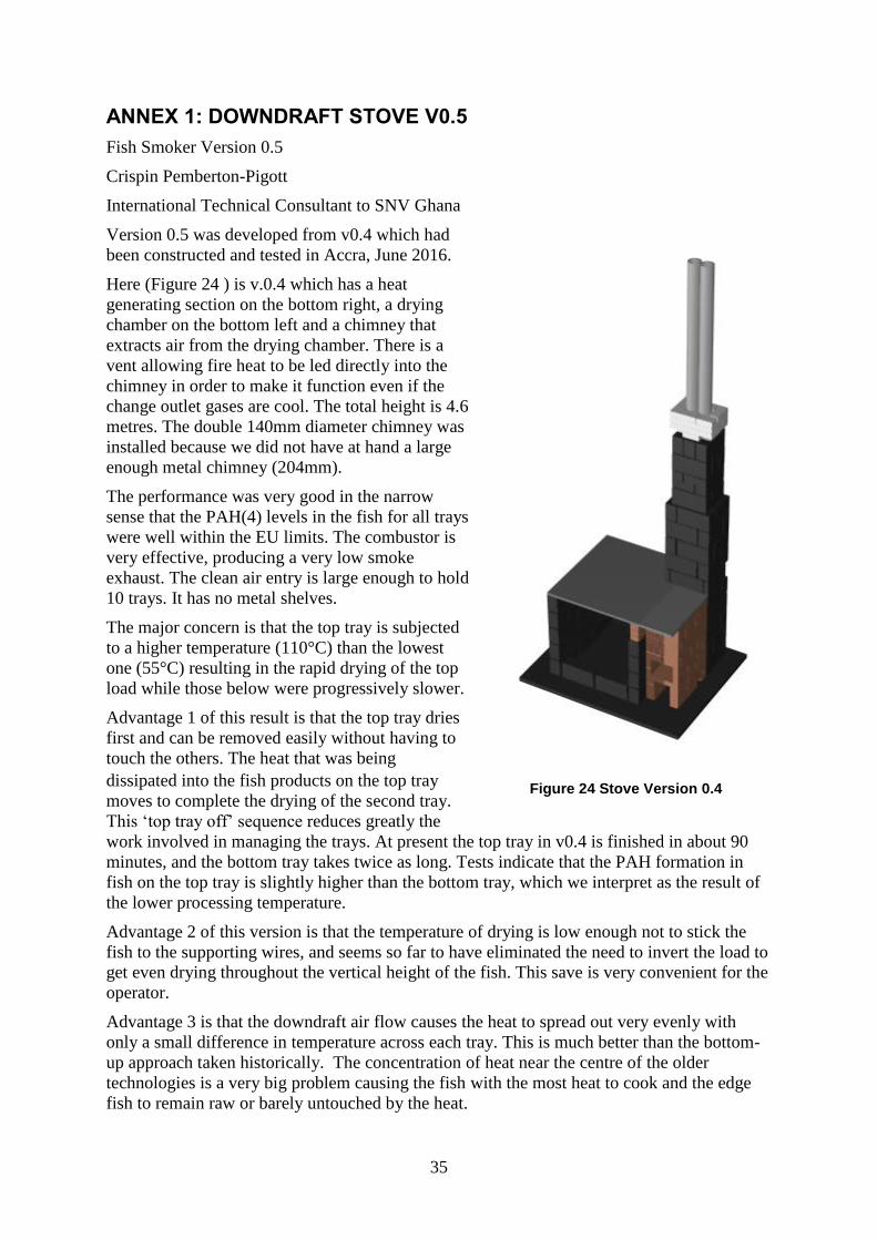
Version 0.5 was developed from v0.4 which had
been constructed and tested in Accra, June 2016.
Here (Figure 24 ) is v.0.4 which has a heat
generating section on the bottom right, a drying
chamber on the bottom left and a chimney that
extracts air from the drying chamber. There is a
vent allowing fire heat to be led directly into the
chimney in order to make it function even if the
change outlet gases are cool. The total height is 4.6
metres. The double 140mm diameter chimney was
installed because we did not have at hand a large
enough metal chimney (204mm).
The performance was very good in the narrow
sense that the PAH(4) levels in the fish for all trays
were well within the EU limits. The combustor is
very effective, producing a very low smoke
exhaust. The clean air entry is large enough to hold
10 trays. It has no metal shelves.
The major concern is that the top tray is subjected
to a higher temperature (110°C) than the lowest
one (55°C) resulting in the rapid drying of the top
load while those below were progressively slower.
Advantage 1 of this result is that the top tray dries
first and can be removed easily without having to
touch the others. The heat that was being
dissipated into the fish products on the top tray
moves to complete the drying of the second tray.
This ‘top tray off’ sequence reduces greatly the
work involved in managing the trays. At present the top tray in v0.4 is finished in about 90
minutes, and the bottom tray takes twice as long. Tests indicate that the PAH formation in
fish on the top tray is slightly higher than the bottom tray, which we interpret as the result of
the lower processing temperature.
Advantage 2 of this version is that the temperature of drying is low enough not to stick the
fish to the supporting wires, and seems so far to have eliminated the need to invert the load to
get even drying throughout the vertical height of the fish. This save is very convenient for the
operator.
Advantage 3 is that the downdraft air flow causes the heat to spread out very evenly with
only a small difference in temperature across each tray. This is much better than the bottom-
up approach taken historically. The concentration of heat near the centre of the older
technologies is a very big problem causing the fish with the most heat to cook and the edge
fish to remain raw or barely untouched by the heat.
Figure 24 Stove Version 0.4

36
Advantage 4 is that smoke production in the new combustor is so low as to leave the fish
dried, virtually ‘unsmoked’. This means the amount of smoke, and the type of smoke desired,
can be added afterwards in a separate operation. This two-stage processing is capable of
delivering EU-compliant food products.
New developments
The high processing temperature and spatially inhomogeneous heating and drying are the
major challenges encountered with the older technologies. Downdraft air flow seems to
resolve this so well, it should be shared as the only approach worth considering when
equipment cost is an over-riding factor. The approach to the distribution of heat (self-
levelling in a descending air column) is automatic and inexpensive. The bottom-up method
requires air dispersion plates and baffles. Further, even when correct, they only operate really
well at one firepower level and air flow rate.
Version 0.5 is proposed to add a circulation component to the airflow without disrupting the
spatial distribution achieved with the downdraft flow. The proposal is to provide an uplift on
one side of the chamber driven by the fire and inducted behind a false back wall. The
introduction of the gas flow in this manner will create an overturning circulation at a much
higher rate than the air extraction rate into the chimney. As a result the air will flow vertically
downwards, then recirculate up again, pushed by the incoming hot air. The overall effect will
be to reduce the vertical temperature inhomogeneity between trays. The expected result is
that the top and bottom trays will dry in more or less the same amount of time, certainly
reducing the current difference. It will permit the fire to be operated at a higher power
without increasing the processing temperature of the top tray.
The delivered benefits should be: reduced fuel consumption, faster processing of the whole
load and less attention required by the operator.
Version 0.5
Materials are:
standard local bricks,
125mm cement blocks
160mm cement blocks
cast concrete top
204mm metal chimney
ash-clay mortar for firebox
See the complete set of PDF files for construction information (63 files).

37
Figure 25 Version 0.5 of stove
Size
The drying chamber is centred approximately on the combustor and chimney. It doesn’t have
to be exact. The width of the chamber can be varied by moving the walls apart or closer to
suite various sizes of tray. If the trays are much larger and the load heavier, it will be
desirable to increase the firepower. This means substituting the combustor with another one.
This can be done independently of the chamber. More firepower means a wider wood
chamber and a ‘flame tube’ with a larger cross sectional area. The grate will be
correspondingly wider and the combustor does not have to be taller.
Combustor
The fire chamber drawings can be created separately from the drying chamber, and can
perhaps be constructed by someone more skilled than the drying chamber. As the power
increases, the air passage under the side wall will be widened. Contractors should probably
have a fire chamber specialist construct that first, perhaps with the chimney up to waist height
and the bleeder installed - that is where most of the skill is needed.
Wooden frame under the trays
Not shown is the wood frame that should underlie the trays. It will make life easier when
sliding in longer trays.

38
False wall at the back keyed into the side walls:
The bottom course passes into the side walls. The middle one doesn't. The top one can, and
should, because people will slam the full trays back into the chamber, hitting the back wall.
When the heat and cooling fractures the mortar joints, the top course being keyed into the
side walls will keep it working for years.
Table 2 Construction sequence for 0.5 version of stove
Construction sequence

39

40

41
Figure 26 Construction plan for 0.5 version of stove.

42
Fish at this area, about 6
inches from the outer wall
gets cooked. The rest do
not cook at all not even
after 5 hours.
ANNEX 2: MORRISON/CHORKOR RETROFIT DESIGN
The stove was constructed to the exact dimensions as in the documents submitted by the
international consultant.
Observations
There is an incomplete combustion of wood resulting in high production of charcoal
Introducing a cover at some point raised the temperature at the center from 33℃ to
50℃.
The stove could not cook fish after 5 hrs.
There were oil drops on the metal plate, as well as in the gap between the wall of the
combustion chamber and the outer wall. We anticipate continual deposit of oil and
blood at the place may cause some health issues.
Figure 27 Retrofit of Morrison/ Chorkor stoves
82
℃ 33
℃

43
Figure 28 SNV Fish Smoker – Morrison Stove Retrofit View 1
Figure 29 SNV Fish Smoker – Morrison Stove Retrofit View 2
General approach
This retrofit involves opening a new hole in the front and patching the existing fire hole. It
requires a new hold made through the back wall to admit air and to help clean out the ash that
falls through the grate.
The combustor is basically the same as the Version 0.4 and 0.5 (the DownDraft models). The
upper portion of it is shorter and diverts the fire to the left as it enters the air mixing chamber.

44
Figure 30 Retrofit view of Morrison Stove
View 1
The walls shown are the standard height of 771mm. On top of the combustor sits a metal
plate 475 x 475mm with a thickness of 2mm or more. It may require holes in it to provide
some heat to the centre of the plate, however this must only comprise a small percentage of
the total air flow.
The plate rests loose on the four supports. It might be changed to a larger dimension such as
475 x 625 to push the hot gases towards the ends of the chamber.
The top course of 4 bricks are 100mm square and serve to create an exhaust path for the hot
air. The height of the supports should be 50mm or more. A brick is suitable (63mm) but the
extra 13mm of height is not required.
The next course is optional and it is not known at this time if it is required. It is preferred to
build the unit as shown and test it. This will require raising the entire working deck enough to
lift the bottom tray above the metal plate, preferable by 75mm or so. If the system works well
(with the addition of holes in the plate as needed) then the second course of bricks can be
removed to see if it still works. The volume contained in the second-from-top course of
bricks on their side provides a mixing space for air and hot gases.
The back section is for air entry only, and has a cap of 30mm thick cast concrete, measuring
520 x 360mm. This cap does not get very hot.
Wooden frame
The latest Morrison Stove includes a built-in wooden frame. This is not shown on the
drawing and should be fitted as necessary and appropriate.
Fish oil dripping
It is well known that the roasting of the fish oil dripping from the product onto the hot parts
of the stove creates PAH. The operating temperature of the lower chamber is significantly
reduced by this design, save the metal plate which may or may not be cooled sufficiently in
the air mixing chamber. It is expected that with the greatly reduced operating temperature, the
formation of PAH from dripping oil may be significantly reduced. It should be tested to see if
this is the case. A drip tray is to be avoided if this change removes most of the PAH problem.

45
If a drip tray has to be installed, the gap between the plate and the product (lowest tray) must
be increased to enable all hot air to get under the lowest tray, remembering that without
perforations, the centre will be difficult to heat evenly.
Metal plate
The plate is shown without any perforations because they may not be necessary, and if they
are, it will have to be determined by experiment, where to put them and how big they should
be. At this time I am inclined to recommend that the holes be made with a cutting disk (angle
grinder) which would make them 3mm wide and about 150mm long. The number and
position is to be determined by examining the dried product.
Figure 31 Drawing Retrofit Combustor


