Low-Noise, High-Strength, Spiral-Bevel Gears for ... · PDF fileLow-Noise, High-Strength,...
15
RESEARCH LABORATORY -'7098 NASA Army Research Laboratory Technical Memorandum 106080 Memorandum Report ARL—MR-71 AIAA-93-2149 Low-Noise, High-Strength, Spiral-Bevel Gears for Helicopter Transmissions David G. Lewicki and Robert E Handschuh Vehicle Propulsion Directorate U.S. Army Research Laboratory Lewis Research Center Cleveland, Ohio Zachary S. Henry Bell Helicopter Textron, Inc. Fort Worth, Texas and Faydor L. Litvin University of Illinois at Chicago Chicago, Illinois Prepared for the 29th Joint Propulsion Conference and Exhibit cosponsored by the AIAA, SAE, ASME, and ASEE Monterey, California, June 28-30, 1993 NASA https://ntrs.nasa.gov/search.jsp?R=19930013830 2018-05-25T23:24:49+00:00Z
Transcript of Low-Noise, High-Strength, Spiral-Bevel Gears for ... · PDF fileLow-Noise, High-Strength,...

RESEARCH LABORATORY
-'7098
NASA
Army Research LaboratoryTechnical Memorandum 106080
Memorandum Report ARL—MR-71
AIAA-93-2149
Low-Noise, High-Strength, Spiral-BevelGears for Helicopter Transmissions
David G. Lewicki and Robert E HandschuhVehicle Propulsion DirectorateU.S. Army Research LaboratoryLewis Research CenterCleveland, Ohio
Zachary S. HenryBell Helicopter Textron, Inc.Fort Worth, Texas
and
Faydor L. LitvinUniversity of Illinois at ChicagoChicago, Illinois
Prepared for the29th Joint Propulsion Conference and Exhibitcosponsored by the AIAA, SAE, ASME, and ASEEMonterey, California, June 28-30, 1993
NASA
https://ntrs.nasa.gov/search.jsp?R=19930013830 2018-05-25T23:24:49+00:00Z

LOW-NOISE, HIGH-STRENGTH, SPIRAL-BEVEL GEARS FOR HELICOPTER TRANSMISSIONS
David G. Lewicki and Robert F. HandschuhVehicle Propulsion Directorate
U.S. Army Research LaboratoryLewis Research CenterCleveland, Ohio 44135
Zachary S. HenryBell Helicopter Textron, Inc.
Fort Worth, Texas 76101
and
Faydor L. LitvinUniversity of Illinois at Chicago
Chicago, Illinois 60680
Abstract
Improvements in spiral-bevel gear design wereinvestigated to support the Army/NASA AdvancedRotorcraft Transmission program. Program objectiveswere to reduce weight by 25 percent, reduce noise by10 dB, and increase life to 5000 hr mean-time-between-removal. To help meet these goals, advanced-designspiral-bevel gears were tested in an OH-58D helicoptertransmission using the NASA 500-hp Helicopter Trans-mission Test Stand. Three different gear designs testedincluded: (1) the current design of the OH-58D trans-mission except gear material X-53 instead of AISI 9310,(2) a higher-strength design the same as the current butwith a full fillet radius to reduce gear tooth bendingstress (and thus, weight), and (3) a lower-noise designthe same as the high-strength but with modified toothgeometry to reduce transmission error and noise. Noise,vibration, and tooth strain tests were performed andsignificant gear stress and noise reductions wereachieved.
Introduction
Spiral-bevel gears are used extensively in rotorcraftapplications to transfer power and motion through non-parallel shafts. In helicopter applications, spiral-bevelgears are used in main-rotor and tail-rotor gearboxes todrive the rotors. In tilt-rotor applications, they are usedin interconnecting drive systems to provide mechanicalconnection between two prop-rotors in case one enginebecomes inoperable. Even though spiral-bevel gears havehad considerable success in these applications, they area main source of vibration in gearboxes, and thus, amain source of noise in cabin interiors (Lewicki and Coy,1987; Mitchell, et al., 1986). In addition, higher strengthand lower weight are required to meet the needs of
future aircraft (Vialle, 1991. An effort to improve thetechnology of components such as spiral-bevel gears hasbeen the Advanced Rotorcraft Transmission (ART)program.
The ART program was an Army-funded, ArmyNASA program to develop and demonstrate lightweight,quiet, durable drive systems for next generation rotor-craft (Bill, 1990). The ART program goals were toreduce drive system weight by 25 percent, reduce noiseby 10 dB, and increase life to 5000 hr mean-time-between-removal by using new ideas in gear configura-tion, transmission concepts, and airframe-drive trainintegration. The success of the ART design configura-tions in meeting the program goals depended on thesuccessful incorporation of certain critical, advancedtechnologies into the preliminary designs. The U.S.Army Vehicle Propulsion Directorate, NASA LewisResearch Center, Bell Helicopter Textron (one ARTcontractor participant), the University of Illinois atChicago (subcontractor to Bell Helicopter Textron), andthe Gleason Works (subcontractor to Bell HelicopterTextron) were involved in a joint project to improvespiral-bevel gears. The project goals were to reduce bevelgear noise and increase strength through changes in geartooth surface geometry, and tooth fillet and root designs(Henry, 1991; Henry, 1992).
Various investigators have studied spiral-bevelgears and their influence on vibration and noise (Litvinand Zhang, 1991a; Gosselin, 1991; Fong and Tsay,1992). Most agree that transmission error, defined as thedifference in relative motion of an output gear withrespect to the input pinion, is the major contributor toundesirable vibration and noise. A common practice isto modify spiral-bevel gear surface topology to permitoperation in a misaligned mode. Over compensation forthis type of operation, however, leads to large
1

transmission error and higher noise and vibration levels.In the Army/NASA/Bell joint project, gears with toothsurfaces designed for reduced transmission errors usingmethods of Litvin and Zhang (1991a) were manufac-tured and tested. The teeth were designed to exhibit aparabolic function of transmission error at a controlledlow level (8 to 10 arc sec). The low level of transmissionerror reduces the vibration and noise caused by themesh. The new tooth geometries for this design wereachieved through slight modification of the machine toolsettings used in the manufacturing process. The designanalyses addressed tooth generation, tooth contactanalysis, transmission error prediction, and effects ofmisalignment (Litvin and Zhang, 1991a; Litvin et al.,1991b; Litvin et al., 1991c).
Also as part of the Army/NASA/Bell project, gearswith tooth fillet and root modifications to increasestrength were manufactured and tested. By increasingthese radii, reduced stresses were achieved, and thus,increased strength. Tooth fillet rad ii larger than those oncurrent gears were made possible by recent advances inspiral-bevel gear grinding technology (Scott, 1991).Advanced gear grinding was achieved through redesignof a current gear grinder and the addition of computernumerical control.
The objective of this report is to describe theresults of the experiments to evaluate advanced spiral-bevel gear designs. The work was part of a joint ArmyNASA/Bell project in support of the ART program.Experimental tests were performed on the OH-58Dhelicopter main-rotor transmission in the NASA 500-hpHelicopter Transmission Test Stand. The baselineOH-58D spiral-bevel gear design, a low-noise design,and a high-strength design were tested. Results of noise,vibration, and tooth strain tests are presented.
Apparatus
OH-58D Main-Rotor Transmission
The OH-58 Kiowa is an Army single-engine, light,observation helicopter. The OH -58D is an advanced ver-sion developed under the Army Helicopter ImprovementProgram (AHIP). The OH-58D main-rotor transmissionis shown in Fig. 1. It is currently rated at maximumcontinuous power of 346 kW (464 hp) at 6016 rpm inputspeed, with the capability of 10 sec torque transients to485 kW (650 hp), occurring once per hour, maximum.The main-rotor transmission is a two-stage reductiongearbox with an overall reduction ratio of 15.23:1. Thefirst stage is a spiral-bevel gear set with a 19-toothpinion that meshes with a 62-tooth gear. Triplex ballbearings and one roller bearing support the bevel-pinionshaft. Duplex ball bearings and one roller bearing
support the bevel-gear shaft. Both pinion and gear arestraddle mounted.
A planetary mesh provides the second reductionstage. The bevel-gear shaft is splined to a sun gear shaft.The 27-tooth sun gear meshes with four 35-tooth planetgears, each supported with cylindrical roller bearings.The planet gears mesh with a 99-tooth fixed ring gearsplined to the transmission housing. Power is taken outthrough the planet carrier splined to the output mastshaft. The output shaft is supported on top by a split-inner-race ball bearing and on bottom by a roller bear-ing. The 62-tooth bevel gear also drives a 27-toothaccessory gear. The accessory gear runs an oil pump,which supplies lubrication through jets and passagewayslocated in the transmission housing.
Spiral-Bevel Test Gears
Three different spiral-bevel gear designs weretested. The first was the baseline OH-58D design.Table I lists a variety of parameters for this baseline set.The reduction ratio of the bevel set is 3.26:1. The gearswere made using standard aerospace practices where thesurfaces were carburized and ground. The material usedfor all test gears was X-53 (AMS 6308) rather than theconventional AISI 9310 (AMS 6265).
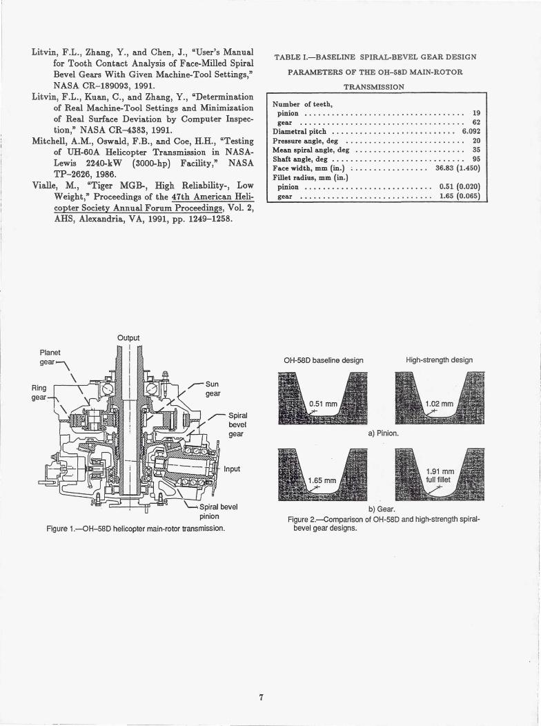
The second spiral-bevel design tested was anincreased strength design. The configuration was identi-cal to the baseline except that the tooth fillet radius ofthe pinion was increased from 0.51 to 1.02 mm (0.020 to0.040 in.), and the gear was made full fillet (Fig. 2). Thehigh-strength design was made possible by recentadvances in gear grinding technology (Scott, 1991).
The third spiral-bevel design tested was a low-noisedesign. The low-noise design was identical to theincreased-strength design except the pinion was slightlyaltered to reduce transmission error. The gear memberwas unchanged. The low-noise design was based on theidea of local synthesis that provided at the mean contactpoint the following conditions of meshing and contact(Litvin and Zhang, 1991a): (1) the required gear ratioand its derivative, (2) the desired direction of thetangent to the contact path, and (3) the desired majoraxis of the instantaneous contact ellipse. The localsynthesis was complemented with a tooth contactanalysis. Using this approach, the machine tool settingsfor reduced noise were determined. As with the high-strength design, precise control of the manufacturedtooth surfaces were made possible by advances in thefinal grinding operation machine tool (Scott, 1991).Figure 3 gives a topological comparison between a low-noise and baseline spiral-bevel pinion tooth. The dottedlines are the baseline tooth datum and the solid lines are
2
the measured difference in topology of a low-noise gearcompared to the baseline. Solid lines above the dottedplain indicate an addition of material and lines belowthe plain indicate a removal. The effect of the topologi-cal change in the low-noise design was a reduction inoverall crowning of the tooth, leading to an increase incontact ratio and reduced transmission error.
NASA 500-HP Helicopter Transmission Test Stand
The OH-58D transmission was tested in the NASALewis 500-hp helicopter transmission test stand (Fig. 4).The test stand operates on the closed-loop or torque-regenerative principle. Mechanical power recirculatesthrough a closed loop of gears and shafting, part ofwhich is the test transmission. The output of the testtransmission attaches to the bevel gearbox. The outputshaft of the bevel gearbox passes through a hollow shaftin the closing-end gearbox and connects to the differen-tial gearbox. The output of the differential attaches tothe hollow shaft in the closing-end gearbox. The outputof the closing-end gearbox connects to the speed de-creaser gearbox. The output of the speed decreases gear-box attaches to the input of the test transmission,thereby closing the loop.
A 149-kW (200-hp) variable-speed direct-current(dc) motor powers the test stand and controls the speed.The motor output attaches to the closing-end gearbox.The motor replenishes losses due to friction since powerrecirculates around the loop. An 11-kW (15-hp) domotor provides the torque in the closed loop. The motordrives a magnetic particle clutch. The clutch outputdoes not turn but exerts a torque. This torque is trans-ferred through a speed reducer gearbox and a chaindrive to a large sprocket on the differential gearbox. Thetorque on the sprocket applies torque in the closed loopby displacing the gear attached to the output shaft ofthe bevel gearbox with respect to the gear connected tothe input shaft of the closing-end gearbox. This is donewithin the differential gearbox through use of a com-pound planetary system where the planet carrierattaches to the sprocket housing. The magnitude oftorque in the loop is adjusted by changing the electricfield strength of the magnetic particle clutch.
A mast shaft loading system in the test stand sim-ulates rotor loads imposed on the OH-58D transmissionoutput mast shaft. The OH-58D transmission outputmast shaft connects to a loading yoke. Two vertical loadcylinders connected to the yoke produce lift loads. A14 000-kPa (2000-psig) nitrogen gas system powers thecylinders. Pressure regulators connected to the nitrogensupply of each of the load cylinders adjust the magni-tude of lift. Note that in the OH-58D design, the trans-mission at no-load is misaligned with respect to the
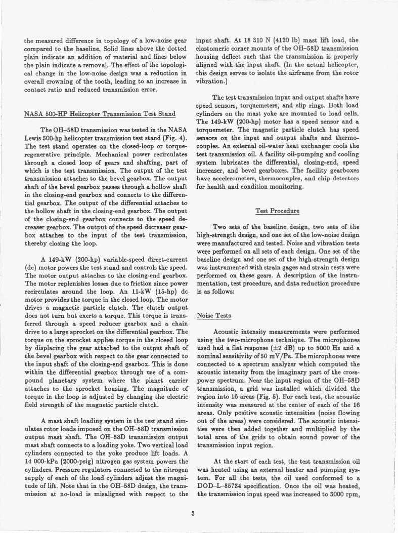
input shaft. At 18 310 N (4120 lb) mast lift load, theelastomeric corner mounts of the OH-58D transmissionhousing deflect such that the transmission is properlyaligned with the input shaft. (In the actual helicopter,this design serves to isolate the airframe from the rotorvibration.)
The test transmission input and output shafts havespeed sensors, torquemeters, and slip rings. Both loadcylinders on the mast yoke are mounted to load cells.The 149-kW (200-hp) motor has a speed sensor and atorquemeter. The magnetic particle clutch has speedsensors on the input and output shafts and thermo-couples. An external oil-water heat exchanger cools thetest transmission oil. A facility oil-pumping and coolingsystem lubricates the differential, closing-end, speedincreaser, and bevel gearboxes. The facility gearboxeshave accelerometers, thermocouples, and chip detectorsfor health and condition monitoring.
Taat P—Prinrn
Two sets of the baseline design, two sets of thehigh-strength design, and one set of the low-noise designwere manufactured and tested. Noise and vibration testswere performed on all sets of each design. One set of thebaseline design and one set of the high-strength designwas instrumented with strain gages and strain tests wereperformed on these gears. A description of the instru-mentation, test procedure, and data reduction procedureis as follows:
Noise Tests
Acoustic intensity measurements were performedusing the two-microphone technique. The microphonesused had a flat response (±2 dB) up to 5000 Hz and anominal sensitivity of 50 mV/Pa. The microphones wereconnected to a spectrum analyzer which computed theacoustic intensity from the imaginary part of the cross-power spectrum. Near the input region of the OH-58Dtransmission, a grid was installed which divided theregion into 16 areas (Fig. 5). For each test, the acousticintensity was measured at the center of each of the 16areas. Only positive acoustic intensities (noise flowingout of the areas) were considered. The acoustic intensi-ties were then added together and multiplied by thetotal area of the grids to obtain sound power of thetransmission input region.
At the start of each test, the test transmission oilwas heated using an external heater and pumping sys-tem. For all the tests, the oil used conformed to aDOD—L-85734 specification. Once the oil was heated,the transmission input speed was increased to 3000 rpm,
3

a nominal amount of torque was applied, and mast liftload was applied to align the input shaft (18 310 N,4120 lb). The transmission input speed and torque werethen increased to the desired conditions. The tests wereperformed at 100-percent transmission input speed(6016 rpm) and torques of 50, 75, 100, and 125-percentof maximum design. The transmission oil inlet tempera-ture was set at 99 °C (210 °F). After the transmissionoil outlet stabilized (which usually required about20 min), the acoustic intensity measurements weretaken. The time to obtain the acoustic intensity meas-urements of the 16 grid points was about 30 min. Foreach acoustic intensity spectrum at a grid point, 100frequency-domain averages were taken. This data wascollected by a computer. The computer also computedthe sound power spectrum of the grids after all themeasurements were taken.
Vihrstion TPSts
Ten piezoelectric accelerometers were mounted atvarious locations on the OH-58D transmission housing(Fig. 6). The accelerometers were located near the inputspiral-bevel area (accelerometers 1, 2, and 10, measuringradially to the input shaft), the ring gear area (3, 4,and 9, measuring radially to the planetary), and on thetop cover (5 to 8, measuring vertically). Accelerometers1 to 8 had a 1 to 25 000-Hz (f3 dB) response, 4 mV/gsensitivity, and integral electronics. Accelerometers 9and 10 had a 2 to 6000-11z (±5 percent) response andrequired charge amplifiers.
The vibration tests were performed in conjunctionwith the noise tests. After collecting the acoustic intens-ity data for a given test, the vibration data was recordedon tape and processed off-line. The vibration data waslater analyzed using time averaging (Fig. 7). Here, thevibration data recorded on tape was input to a signalanalyzer along with a tach pulse from the transmissioninput shaft. The signal analyzer was triggered from thetach pulse to read the vibration data when the transmis-sion input shaft was at the same position. The vibrationsignal was then averaged in the time domain using 100averages. This technique removed all the vibrationwhich was not synchronous to the input shaft. Beforeaveraging, the major tones in the vibration spectrum ofthe OH-58D baseline design were the spiral-bevel andplanetary gear fundamental frequencies and harmonics.Time averaging removed the planetary contribution,leaving the spiral-bevel contribution for comparing thedifferent design configurations.
Strain Tests
Twenty strain gages were mounted on the spiral-bevel pinions and 26 gages were mounted on the spiral-bevel gears of one set each of the baseline and high-strength designs (Figs. 8 and 9). Gages were positionedevenly across the tooth face widths with some in thefillet area and some in the root area of the teeth. Thefillet gages were placed on the drive side of the teeth.The fillet gages were also positioned at a point on thetooth cross-section where a line at a 45° angle withrespect to the tooth centerline intersects the tooth profile(Fig. 8(b)). The fillet gages were placed there to measuremaximum tooth bending stress. Previous studies on spurgears showed that the maximum stresses were at a line30 0 to the tooth centerline (Hirt, 1976). 45° was chosenfor the current tests to minimize the possibility of thegages being destroyed due to tooth contact. In additionto maximum tensile stresses, root stresses can becomesignificant in lightweight, thin-rimmed aerospace gearapplications (Drago, 1990). Thus, root gages werecentered between teeth in the root to measure gear rimstress. Tooth fillet and root gages were placed onsuccessive teeth to determine loading consistency. Thegrid length of the gages was 0.381 mm (0.015 in.) andthe nominal resistance was 120 Q. The gages wereconnected to conditioners using a Wheatstone bridgecircuitry and using a quarter-bridge arrangement.
Static strain tests were performed on both thespiral-bevel pinions and gears. A crank was installed onthe transmission input shaft to manually rotate theshaft to the desired position (Fig. 10). A sensor wasinstalled on the transmission output shaft to measureshaft position. At the start of a test, the transmissionwas completely unloaded and the strain gage condition-ers were zeroed. Conditioner spans were then determinedusing shunt calibrations. The transmission was loaded(using the facility closed-loop system) to the desiredtorque, the shaft was positioned, and the strain readingswere obtained using a computer. This was done for avariety of positions to get strain as a function of shaftposition for the different gages. At the end of a test, thetransmission was again completely unloaded and theconditioner zeroes were checked for drift. All static testswere performed at room temperature.
Dynamic strain tests were performed only on thespiral-bevel pinions. The pinion gages were connected toslip rings mounted on the input shaft. A slip ring assem-bly for the spiral-bevel gear was unavailable, and thus,dynamic strain tests of the gear were not performed. The
4

test procedure was basically the same as the noise andvibration tests, except that the transmission was not runas long in order to maximize strain gage life.
Results and Discussion
Noise Tests
The noise spectrum (sound power versus frequency)at 100-percent torque is given in Fig. 11. The resultsshown are for set 1 of the baseline configuration andset 1 of the low-noise configuration. Among the domi-nant spikes in the spectrum for the baseline design arethe spiral-bevel meshing frequency (1905 Hz) and secondharmonic (3810 Hz). Note that these tones are signifi-cantly reduced for the low-noise design. Other dominanttones in the spectrum are at the planetary meshing fre-quencies (fundamental at 652 Hz). The planetary toneswere not affected by the low-noise design. Tones fromthe facility closing-end gearbox (Fig. 4) were alsodominant in the spectrum (fundamental at 790 Hz) andas expected were not affected by the low-noise design.
The effect of torque on sound power at the spiral-bevel frequencies is given in Fig. 12. Both sets of thebaseline and high-strength designs and one set of thelow-noise design are included. The sound power is thecumulation of the spiral-bevel meshing frequency(1905 Hz) and second harmonic (3810 Hz). The baselineand high-strength designs produced basically the samenoise since the difference between them was in the toothfillet geometry. There was some scatter in the baselineand high-strength results due to manufacturing toler-ances of the different sets and assembly tolerances. Tocheck assembly tolerances, the low-noise tests wererepeated two times. Here, the gears were completeddisassembled and reassembled in the transmission, andthe tests were repeated. The results showed the sametrend and were repeatable to within about 2 dB. Thegeneral trend was a significant decrease in spiral-bevelgear noise for the low-noise design compared to thebaseline and high-strength design. At 100-percenttorque, the noise due to the spiral-bevel mesh was 12 to19 dB lower than that of the baseline and high-strengthdesigns. Also, a decrease in noise was most prevalent at100 and 125-percent torque and less prevalent at 50 and75-percent torque.
Vibration Results
The vibration spectrum (time-averaged accelerationversus frequency) for accelerometer 1 (input spiral-bevelhousing) at 100-percent torque is given in Fig. 13. Aswith Fig. 11, the results compare set 1 of the baseline toset 1 of the low-noise configuration. The figure clearly
shows the dominant spikes for the baseline design at thespiral-bevel meshing frequencies, and the significantreduction in spiral-bevel gear vibration for the low-noisedesign. The results of the other nine accelerometers weresimilar.
The effect of torque on vibration for accelerometers1 and 5 is given in Fig. 14. Shown in the figure is time-averaged acceleration processed up to 10 000 Hz. Theresults are root-mean-square (rms) calculations of thetime-domain signals. Since the time-averaging removedvibration nonsynchronous to the input shaft, the resultsin Fig. 14 were basically the cumulation of the spiral-bevel meshing frequency (1905 Hz) and second throughfifth harmonics.
As with the noise measurements, the vibration forthe baseline and high-strength designs were similar butwith scatter. Again, the figure clearly shows a significantreduction in spiral-bevel gear vibration for the low-noisedesign compared to the baseline and high-strengthdesigns. Like the noise results, the reduction in vibrationfor the low-noise design was greater at the highertorques (100 and 125 percent). The results of the othereight accelerometers were similar. From the results of all10 accelerometers and at 100-percent torque, the vibra-tion for the low-noise design due to the spiral-bevelmesh was on the average 5 to 10 g's lower than that ofthe baseline and high-strength designs.
Strain Tests
Figure 15 shows the results of a typical staticstrain test of the spiral-bevel pinion. A unia.xial stressfield was assumed to exist at the strain gage and thestress was determined by multiplying the measuredstrain by Young's modulus for steel. For a pinion filletgage, the stress was first compressive, then tensile. Sincethe pinion drove the gear, the compression occurredwhen the tooth in mesh prior to the strain-gaged toothwas loaded, causing compression in the gage. As thepinion rotated, the strain-gaged tooth was loaded insingle-tooth contact and the gage measured the maxi-mum tensile stress. Similar conditions existed for thepinion root gage except the gage measured the stress ofthe pinion rim rather than tooth bending. The resultsfor the spiral-bevel gear were similar to the pinionexcept the tensile stress occurred before the compressionsince the pinion drove the gear.
Figure 16 shows the distribution of maximum ten-sile and compressive stress during contact along thetooth face width for the baseline and high-strength de-signs. The most important item to note is the reductionin maximum tensile bending stress of the high-strengthdesign compared to the baseline design. The maximum
5
tensile stress of the high-strength design was reduced onthe average 27 percent compared to the baseline for thespiral-bevel pinion (Fig. 16(a)). There was, however, anincrease in the maximum compressive fillet stress for thespiral-bevel pinion. Thus, the alternating stress of thehigh-strength design was reduced on the average 14 per-cent compared to the baseline (the alternating stress isdefined as the maximum tensile stress plus the absolutevalue of the maximum compressive stress). For thespiral-bevel gear, the maximum tensile stress of thehigh-strength design was reduced on the average 10 per-cent compared to the baseline and the alternate wasreduced on the average 12 percent (Fig. 16(c)). Thus,the increase in fillet rad ii of the high-strength design hasa significant benefit in increasing the tooth bendingcapacity of the gear tooth.
There was a significant increase in the maximumcompressive root stress of the high-strength design com-pared to the baseline spiral-bevel pinion (Fig. 16(b)) anda slight increase for the gear (Fig. 16(d)). This wasprobably due to the removal of material for the in-creased fillet, thus lowering the rim thickness. For theOH-58D design, this increase in stress is acceptable, butin general, these effects need to be considered in adesign.
Figure 16 also shows the results of the dynamicstrain tests for the spiral-bevel pinion. The results of thedynamic strain tests matched closely to those of thestatic. The stress-position plots were similar as well asthe maximum and minimum stresses, indicating nodetrimental dynamic effects.
Summary of Results
Advanced-design spiral-bevel gears were tested inan OH-58D helicopter transmission using the NASA500-hp Helicopter Transmission Test Stand. Threedifferent gear designs were tested. The baseline designwas the current design of the OH-58D transmission,except the gear material was X-53 rather than AISI9310. The second design was a higher-strength designwhich was the same as the baseline but incorporated afull fillet radius to reduce gear tooth bending stress. Thethird design was a lower-noise design which was thesame as the high-strength design except the toothgeometry was modified to reduce transmission error andnoise. Noise, vibration, and tooth strain tests wereperformed. The following results were obtained:
1. For the baseline spiral-bevel gear design, domi-nant tones in the noise and vibration spectra occurred atthe spiral-bevel meshing frequencies and harmonics. Asignificant decrease in the spiral-bevel tones resultedfrom the low-noise design. At 100-percent torque, the
noise (sound power) due to the spiral-bevel meshing fre-quencies of the low-noise design was 12 to 19 dB lowerthan that of the baseline and high-strength designs.Using a time-average processing scheme, the spiral-bevelgear vibration of the low-noise design was 5 to 10 g'slower than that of the baseline and high-strengthdesigns.
2. The increased fillet radius of the high-strengthdesign had a significant benefit in decreasing toothbending stress. For tests at 100-percent torque, thespiral-bevel pinion maximum tooth bending stress of thehigh-strength design was on the average 27-percentlower than that of the baseline design. There was,however, an increase in the maximum compressive stressat the center of the tooth root.
References
Bill, R.C., "Advanced Rotorcraft Transmission Pro-gram," NASA TM-103276, 1990.
Drago, R.J., "Design Guidelines for High-CapacityBevel Gear Systems," AE-15 Gear Design, Manu-facturing and Inspection Manual, Society of Auto-motive Engineers, Warrendale, PA, 1990,pp. 105-121.
Fong, Z.H., and Tsay, C.B., "Kinematic Optimizationof Spiral Bevel Gears", Journal of MechanicalDesign, Vol. 114, No. 3, Sept. 1992, pp. 498-506.
Gosselin, C., Cloutier, L., and Brousseau, J., "ToothContact Analysis of High Conformity Spiral BevelGears," Proceedings of the International Confer-ence on Motion and Power Transmissions,Nov. 23-26, 1991, Hiroshima, Japan.
Henry, Z.S., "Advanced Rotorcraft Transmission (ART)—Component Test Results," Presented at the 28thAIAA/ASME/SAE Joint Propulsion Conference,Nashville, TN, July 6-8, 1992.
Henry, Z.S., "Preliminary Design and Analysis of anAdvanced Rotorcraft Transmission," AIAAASME/SAE/ASEE 27th Joint Propulsion Confer-ence, Proceedings, AIAA, Washington, DC, 14 p.,1991.
Hirt, M.C.O., "Stress in Spur Gear Teeth and TheirStrength as Influenced by Fillet Radius," Disserta-tion, American Gear Manufacturers Association,Ph.D. Thesis, 1976.
Scott, H.W., "Computer Numerical Control Grinding ofSpiral Bevel Gears," NASA CR-187175, 1991.
Lewicki, D.G., and Coy, J.J., "Vibration Characteristicsof OH-58A Helicopter Main Rotor Transmission,"NASA TP-2705, 1987.
Litvin, F.L., and Zhang, Y., "Local Synthesis and ToothContact Analysis of Face-Milled Spiral BevelGears," NASA CR-4342, 1991.
6
RigE
Litvin, F.L., Zhang, Y., and Chen, J., "User's Manualfor Tooth Contact Analysis of Face-Milled SpiralBevel Gears With Given Machine-Tool Settings,"NASA CR-189093, 1991.
Litvin, F.L., Kuan, C., and Zhang, Y., "Determinationof Real Machine-Tool Settings and Minimizationof Real Surface Deviation by Computer Inspec-tion," NASA CR-4383, 1991.
Mitchell, A.M., Oswald, F.B., and Coe, H.H., "Testingof UH-60A Helicopter Transmission in NASA-Lewis 2240-kW (3000-hp) Facility," NASATP-2626, 1986.
Vialle, M., "Tiger MGB-, High Reliability-, LowWeight," Proceedings of the 47th American Heli-copter Society Annual Forum Proceedings, Vol. 2,AHS, Alexandria, VA, 1991, pp. 1249-1258.
TABLE I.—BASELINE SPIRAL-BEVEL GEAR DESIGN
PARAMETERS OF THE OH-58D MAIN-ROTOR
TRANSMISSION
Number of teeth,pinion ................................... 19gear .................................... 62
Diametral pitch ........................... 6.092Pressure angle, deg .......................... 20Mean spiral angle, deg ........................ 35Shaft angle, deg ............................. 95Face width, mm (in.) ................. 36.83 (1.450)Fillet radius, mm (in.)
pinion ............................ 0.51 (0.020)gear ............................. 1.65 (0.065)
Output
— Spiralbevelgear
Input
bevelpinion
Figure 1.—OH-58D helicopter main-rotor transmission.
L
a
0.51 mm 1.02 mmAa) Pinion.
x
1.91 mm1.65 mm full fillet
b) Gear.Figure 2.—Comparison of OH-58D and high-strength spiral-
bevel gear designs.
OH-58D baseline design
High-strength design

Toe Topland Heel
Coast side
materialadded
,)aterialremoved
200
15-1
M.
Tc
Dox
ers
.............OH-58D baseline design
Low-noise design
r)rivo ciA.
Figure 3.—Topological comparison of OH-58D and low-noisespiral-bevel pinion.
Figure 4.—NASA Lewis 500-hp helicopter transmission test stand.

WOWAcoustic intensityprobe holder 1%
i^
Figure 5.--Grid for sound intensity measurements.
5 6
0 0 ., 5,7 6,84 3
0 1
Soo
9 ;.02
7 8
a) Top view. b) Side view.
Figure 6.—Accelerometer locations on OH-58D transmission.
C-------------------1^o i
Time- I1 c9averaged
1 . o acceleration0 Frequency
_ ITape i Computer
recorderI 'II RMS acceleration' 100 iiI ^
averagesAccelerometer
sign I ian
tach pulse i------------------- ^Signal analyzer
Figure 7.—Data reduction scheme of vibration tests.
9

? oe
a) Gage numbering.
Fillet gage r Root gage
i!
450^I
Figure 9.--Strain gage locations on spiral-bevel gear-
;.W",
Fillet gages T- Z:-- –
52-.:ss2
b) Cross-sectional view.Figure 8.—Strain gage locations on spiral-bevel pinion. Figure 10.—Setup for static stress tests.
10

lUO
120
^ 110
Cn 100
_
SO
:C3) 80m
n * Spiral-bevel frequencies17 Planetary frequencies
+ 0 Facility closing-andgearbox frequencies
Baseline designLow-noise design
17V
zi
90
CL
8m O
' 70
— 60
0 Baseline design, set I
* Baseline design, set 2
0 High-strength design, set 1
z^ Low-noise design, set 1
40o 1000 2000 aooO 4000 5000
Frequency, Hz
Figure 1I.—Noise spectrum; test at 100-percent torque.
-7nO 25 50 75 100 125 150
Transmission input torque , % of maximum
Figure 12_Nuise test results; sound power at spiral-bevel meshfrequencies (first two harmonics) versus transmission input torque.
Y,CO
25
20
^15CO
lO
V5
= n
c 30^
eo,25
20
^ 15CO
10cc^ 5Ma) n
5
^
4
3
Ca2
'1
00 2000 4000 6000 8000 10000
Frequency, Hz
F igure 1o,-vuooion spectrum; acce lerometer 1.test at1 00-percent torque.
^ o Baseline om 1----- ----------------------0 Baseline design, set 2
. .......... 13 High-strength design, set 1 ---'
^ 0 High-stronoV` ' design, set 2........... Low'nnisodanign ' vet 1 ---^
-----!---'— '---
^^^^^^ .......... ........''
--- Baseline design `O 25 50 75 100 125 150Low-noise design Transmission input torque, %ofmaximum
a) Accelerometer 1, input spiral-bevel housing.
^
------------/sF- ~O 25 50 75 lVO 125 150
Transmission input torque, %ofmaximum
b> Accelerometer 5 ' top housing.
Figure 14.—Typical vibration test results.
11

1 Mn 1000
N 100 750'e CL 500
50 t 2500- 00
-250-50-500-40 -30 -20 -10 0 10 20 30 40
Pinion shaft position, deg
a)Fillet gage 14.
150 1000
100 750 -----=------=--------------------------------•- - --Y
CL 500 •---.------ :...... ' •,•---••,---------------
w;
250 i ...... :...... :------ :...... ...... -----
N 0 «J 0
-50
-250 ;------; --
50040 -30 -20 -10 0 10 20 30 40Pinion shaft position, deg
b)Root gage 2.Figure 15.—Typical strain test results; spiral-bevel pinion,
100-percent torque.
12

---- Maximum .............................tension
:Maximum........V...---- --- ...... tension
K)Inyimum
Heel Toe
Maximumcompression-: --..-.
Heel : Toe
150900
100 600Y ^
50 300♦ 3 tqN
0 m 0Y
-50 CA)-300
600
150900
Y 100 600
m 50 2 300
N 0 0
-50 N -300
-600
o Baseline desigr, static tests• Baseline design, dynamic testsq High-strength design, static testsn High-strength, design, dynamic tests
150900 Maximum
tensiony 100 600 -- ----- ------ --- .........
50 300 - ------ ......:.........:. ........ .......
N Maximum0 0 compression
-50 -300 ---- ------ ----- . ..:...--- -<-------..Heel Toe
60006 12 18 24 30 36
Position along tooth, mm
a) Spiral-bevel pinion fillet gages.
150
100
900
600 ------Maximum ----- --------------------------a tension
50 300 ------ = :.........m
N 0 0Maximum
-50 -300 ---------.-.. compression
Heel To6000
6 12 18 24 30 36
Position along tooth, mm
b) Spiral-bevel pinion root gages.
0 6 12 18 24 30 36
0 6 12 18 24 30 36
Position along tooth, mm Position along tooth, mm
c) Spiral-bevel gear fillet gages. d) Spiral-bevel gear root gages.
Figure 16.—Strain test results; 100-percent torque.
13
Form Approved_TREPORT DOCUMENTATION PAGE OMB No. 0704-0188
Public reporting burden for this collection of information is estimated to average 1 hour per response, including the time for reviewing instructions, searching existing data sources,gathering and maintaining the data needed, and completing and reviewing the collection of information. Send comments regarding this burden estimate or any other aspect of thiscollection of information, including suggestions for reducing this burden, to Washington Headquarters Services. Directorate for information Operations and Reports, 1215 JeffersonDavis Highway, Suite 1204, Arlington, VA 22202-4302, and to the Office of Management and Budget, Paperwork Reduction Project (0704-0188), Washington, DC 20503.
1. AGENCY USE ONLY (Leave blank) 2. REPORT DATE 3. REPORT TYPE AND DATES COVERED
June 1993 Technical Memorandum4. TITLE AND SUBTITLE 5. FUNDING NUMBERS
Low-Noise, High-Strength, Spiral-Bevel Gears for Helicopter Transmissions
WU-505-62-1011-162211A47A6. AUTHOR(S)
David G. Lewicki, Robert F. Handschuh, Zachary S. Henry,and Faydor L. Litvin
7. PERFORMING ORGANIZATION NAME(S) AND ADDRESS(ES) 8. PERFORMING ORGANIZATION
NASA Lewis Research Center REPORT NUMBER
Cleveland, Ohio 44135-3191
andE-7698Vehicle Propulsion Directorate
U.S. Army Research Laboratory
Cleveland, Ohio 44135-3191
9. SPONSORING/MONITORING AGENCY NAMES(S) AND ADDRESS(ES) 10. SPONSORING/MONITORING
National Aeronautics and Space AdministrationAGENCY REPORT NUMBER
Washington, D.C. 20546-0001 NASA TM-106080and
AIAA-93-2149 U.S. Army Research Laboratory
Adelphi, Maryland 20783-1145 ARL—MR-71
11. SUPPLEMENTARY NOTESPrepared for the 29th Joint Propulsion Conference and Exhibit cosponsored by the AIAA, SAE, ASME, and ASEE, Monterey, Califomia,
June 28-30, 1993. David G. Lewicki and Robert F. Handschuh, Vehicle Propulsion Directorate, U.S. Army Research Laboratory, Lewis
Research Center. Zachary S. Henry, Bell Helicopter Textron, Inc., Fort Worth, Texas 76101. Faydor L. Litvin, University of Illinois at
Chicago, Chicago, Illinois 60680. Responsible person, David G. Lewicki, (216) 433-3970.
12a. DISTRIBUTION/AVAILABILITY STATEMENT 12b. DISTRIBUTION CODE
Unclassified -UnlimitedSubject Category 37
13- ABSTRACT (Maximum 200 words)
Improvements in spiral-bevel gear design were investigated to support the Army/NASA Advanced RotorcraftTransmission program. Program objectives were to reduce weight by 25 percent, reduce noise by 10 dB, and increaselife to 5000 hr mean-time-between-removal. To help meet these goals, advanced-design spiral-bevel gears weretested in an OH-58D helicopter transmission using the NASA 500-hp Helicopter Transmission Test Stand. Threedifferent gear designs tested included: (1) the current design of the OH-58D transmission except gear material X-53instead of AISI 9310, (2) a higher-strength design the same as the current but with a full fillet radius to reduce geartooth bending stress (and thus, weight), and (3) a lower-noise design the same as the high-strength but with modifiedtooth geometry to reduce transmission error and noise. Noise, vibration, and tooth strain tests were performed andsignificant gear stress and noise reductions were achieved.
14. SUBJECT TERMS 15. NUMBER OF PAGES
Transmissions (machine elements); Gears; Noise; Vibration; Strain measurement 1416. PRICE CODE
A0317- SECURITY CLASSIFICATION 18- SECURITY CLASSIFICATION 19. SECURITY CLASSIFICATION 20. LIMITATION OF ABSTRACT
OF REPORT OF THIS PAGE OF ABSTRACT
Unclassified Unclassified Unclassified
NSN 7540-01-280-5500 Standard Form 298 (Rev. 2-89)Prescribed by ANSI Std. Z39-18298-102


![85540168 Bevel Gears in ProE[1]](https://static.fdocuments.net/doc/165x107/544b2fd6b1af9f804f8b4fca/85540168-bevel-gears-in-proe1.jpg)