
Solar Power Installations on Closed Landfills: Technical and ...

ZHP08C/GB
CATA
LOG
UE
2010
High Power
ZucchiniLow-Medium Power
CATALOGUE 2010-2011
TECHNICAL INFORMATION 2LOW-MEDIUM POWER GENERAL CATALOGUE
TECH
NICA
L IN
FORM
ATIO
N
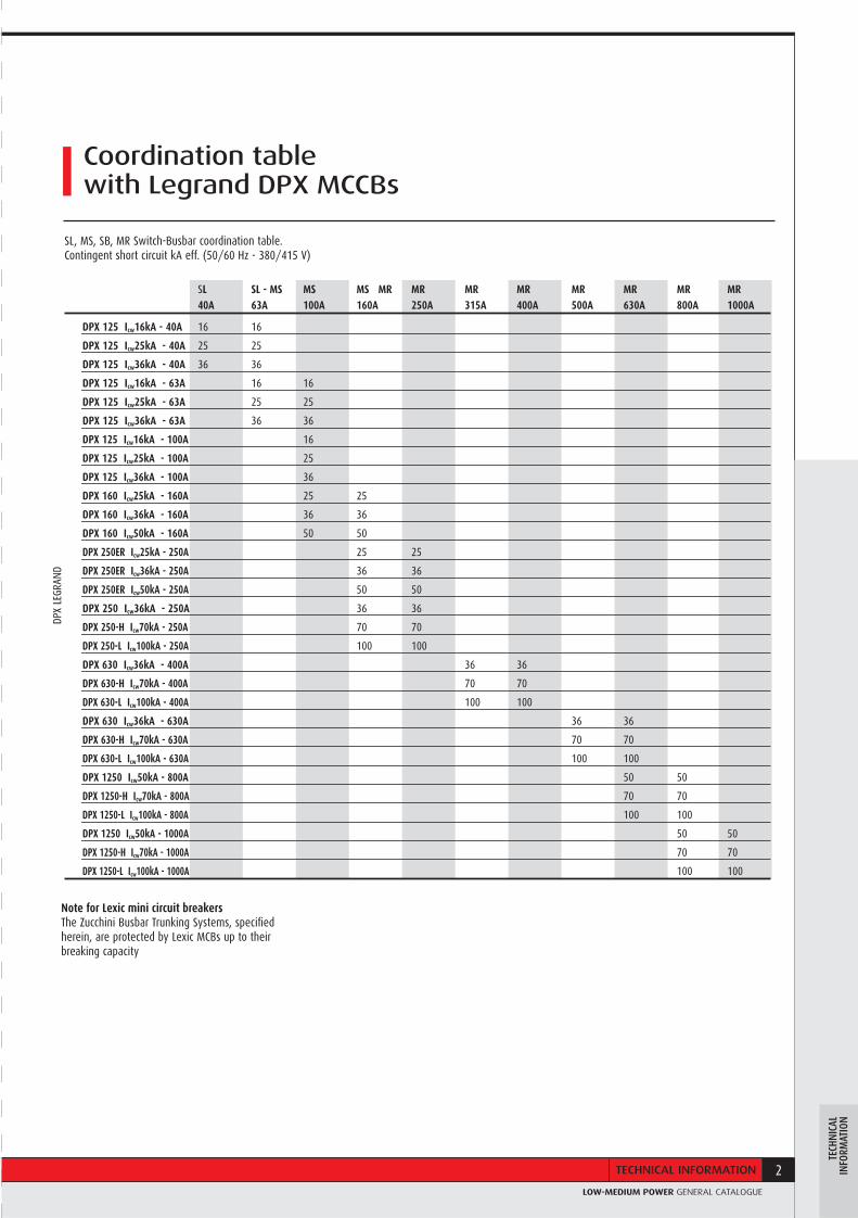
SL SL - MS MS MS MR MR MR MR MR MR MR MR 40A 63A 100A 160A 250A 315A 400A 500A 630A 800A 1000A
DPX 125 Icw16kA - 40A 16 16
DPX 125 Icw25kA - 40A 25 25
DPX 125 Icw36kA - 40A 36 36
DPX 125 Icw16kA - 63A 16 16
DPX 125 Icw25kA - 63A 25 25
DPX 125 Icw36kA - 63A 36 36
DPX 125 Icw16kA - 100A 16
DPX 125 Icw25kA - 100A 25
DPX 125 Icw36kA - 100A 36
DPX 160 Icw25kA - 160A 25 25
DPX 160 Icw36kA - 160A 36 36
DPX 160 Icw50kA - 160A 50 50
DPX 250ER Icw25kA - 250A 25 25
DPX 250ER Icw36kA - 250A 36 36
DPX 250ER Icw50kA - 250A 50 50
DPX 250 Icw36kA - 250A 36 36
DPX 250-H Icw70kA - 250A 70 70
DPX 250-L Icw100kA - 250A 100 100
DPX 630 Icw36kA - 400A 36 36
DPX 630-H Icw70kA - 400A 70 70
DPX 630-L Icw100kA - 400A 100 100
DPX 630 Icw36kA - 630A 36 36
DPX 630-H Icw70kA - 630A 70 70
DPX 630-L Icw100kA - 630A 100 100
DPX 1250 Icw50kA - 800A 50 50
DPX 1250-H Icw70kA - 800A 70 70
DPX 1250-L Icw100kA - 800A 100 100
DPX 1250 Icw50kA - 1000A 50 50
DPX 1250-H Icw70kA - 1000A 70 70
DPX 1250-L Icw100kA - 1000A 100 100
DPX
LEGR
AND
SL, MS, SB, MR Switch-Busbar coordination table. Contingent short circuit kA eff. (50/60 Hz - 380/415 V)
Note for Lexic mini circuit breakers The Zucchini Busbar Trunking Systems, specified herein, are protected by Lexic MCBs up to their breaking capacity
Coordination table with Legrand DPX MCCBs

40 - 63A
25 - 40A
LBLIGHTING BUSWAY
SL SERIE LUCE
HLHIGH LIGHTING
25 - 40A
63 - 100 - 160A
MSMINI SBARRA
160 - 1000A
MRMEDIUM RATING
63 - 250A
TSTROLLEY SYSTEM
LO
W
PO
WE
RM
ED
IU
M
PO
WE
R
TECHNICAL INFORMATION
page 1
page 21
page 43
page 57
page 73
page 109
page 127
Integrated solutionsfor global projects
Legrand is the world specialist in products and systems for electrical installations and information networks:
- Distribution, automation panels and protection equipment
- Cable management (trunking, cable trays and wire mesh)
- Busbars and lighting busbars
Every product and system needed for distributing energy and protecting people and property.
AltisTM industrial cabinetsAtlantic and Marina boxes
Cablofi l cable trays

LOW-MEDIUM POWER GENERAL CATALOGUE
In a context of accelerated globalization and increasingly complex projects, the support of a reliable and competent partner is absolutely essential, a real key to the success of your company.Choosing the Legrand Group means the assurance of benefi ting from global expertise throughout the world thanks to its strong local presence.A vast choice of carefully styled products compose solutions which in turn form coherent systems incorporating the latest technological innovations.Choosing Legrand also means you are sure to be assisted by professionals at your service any time, from your project’s design through to its completion.
Zucchini busbars
ZHP08C/GB
CATA
LOG
UE
2010
High Power
ZucchiniLow-Medium Power
CATALOGUE 2010
XL3 distribution cabinets
DMX, DPX, DX circuit breakers
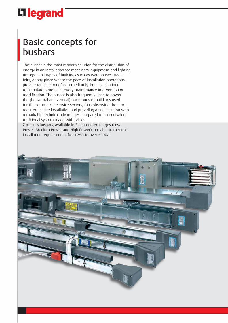
The busbar is the most modern solution for the distribution of energy in an installation for machinery, equipment and lighting fi ttings, in all types of buildings such as warehouses, trade fairs, or any place where the pace of installation operations provide tangible benefi ts immediately, but also continue to cumulate benefi ts at every maintenance intervention or modifi cation. The busbar is also frequently used to power the (horizontal and vertical) backbones of buildings used for the commercial-service sectors, thus observing the time required for the installation and providing a fi nal solution with remarkable technical advantages compared to an equivalent traditional system made with cables.Zucchini’s busbars, available in 3 segmented ranges (Low Power, Medium Power and High Power), are able to meet all installation requirements, from 25A to over 5000A.
Basic concepts for busbars

LOW-MEDIUM POWER GENERAL CATALOGUE
EASY TO DESIGNThe electric design of the busbars is achieved by Zucchini in compliance with the product Standards. The rated current of our busbars is guaranteed at a room temperature of 40 °C (n.d.r. the Standard requires 35 °C). After choosing the busbar which is able to meet the operating current regulations, it will be very easy to verify the voltage drop as well as the protection against overcurrents by using the technical tables available for all our production lines. In particular, these tables defi ne: the short circuit and peak currents that can be supported by the busbar waiting for the protection device located upstream to start operating, the specifi c voltage drop based on the average cos phi of the loads, the losses and other data (R, X, Rpe, etc.) which allow the planning engineer to carry out calculations with electric values, which are not estimated but the result of measurements made during heating and short circuit tests (in certifi ed LOVAG laboratories), which have certifi ed all our product lines.
INTRINSIC SAFETYA busbar does not use large amounts of insulating plastic material and potentially dangerous materials in case of fi re. Furthermore, the plastic materials used for the insulating parts of the busbars are always self-extinguishing (from V0 to V2) and the gas emission is generally very low (Halogen Free). Low electromagnetic emission is another advantage of the busbars compared to that of an equivalent cable system: as a result, the metal plate casing of the busbars serves as a screen for the electric fi eld (shielded enclosure); the extreme vicinity between the phase conductors also reduces the emission of the magnetic fi eld considerably. The tests carried out on one of our 2500A SCP busbars at full operating current has shown that the emission of the magnetic fi eld (magnetic induction) is lower than 10 μT of the Decree at a distance of 0.3m, and lower than 3 μT at a distance of only 0.7m from the busbar. These features make our busbars the unavoidable choice for hospital facilities, data processing centres and
.
.
wherever it is necessary to supply a large amount of power in the vicinity of workplaces and/or sensitive equipment.
When using busbars, the load protection is located very close to the device (decentralized protection); junction boxes can contain protection devices such as thermal magnetic circuit breakers, fuse carriers and motorized switches which allow you to easily and effi caciously manage the system.
Example of an electric characteristics table
Zucchini busbar electromagnetic emission
Basic concepts for busbars
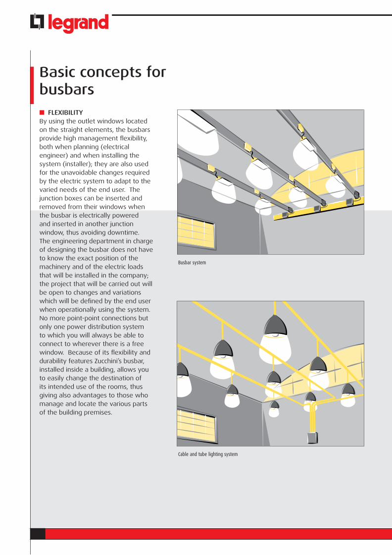
FLEXIBILITYBy using the outlet windows located on the straight elements, the busbars provide high management flexibility, both when planning (electrical engineer) and when installing the system (installer); they are also used for the unavoidable changes required by the electric system to adapt to the varied needs of the end user. The junction boxes can be inserted and removed from their windows when the busbar is electrically powered and inserted in another junction window, thus avoiding downtime. The engineering department in charge of designing the busbar does not have to know the exact position of the machinery and of the electric loads that will be installed in the company; the project that will be carried out will be open to changes and variations which will be defined by the end user when operationally using the system. No more point-point connections but only one power distribution system to which you will always be able to connect to wherever there is a free window. Because of its flexibility and durability features Zucchini’s busbar, installed inside a building, allows you to easily change the destination of its intended use of the rooms, thus giving also advantages to those who manage and locate the various parts of the building premises.
Busbar system
Cable and tube lighting system
LOW-MEDIUM POWER GENERAL CATALOGUE
QUICK INSTALLATIONZucchini’s junction and fixing systems have been designed and created to install busbars easily. In a cable and tray system, the time required to install only the tray is the same used to install a complete system in busbars. Furthermore, given the same capacity, a power busbar, which generally has aluminium conductors, is much lighter than a system made with (copper) trays and cables: lighter weights require a lower number of supporting frames or, in any case, more simple and inexpensive supporting frames. That is why the installation time of a busbar is obviously shorter than a similar system made with cables.
REDUCED DIMENSIONSThe overall dimensions of the busbars are generally smaller than an equivalent system made with cables, especially when the currents to be carried exceed 1000A and when several cables in parallel are necessary to ensure such capacity. Other advantages can be achieved when there are changes of direction where the radius of curvature of the cables is minimal and enough to not damage the insulating material; busbars allow you to change directions with 90° angles, thus optimizing the small spaces used in service areas.
LB - LIGHTING BUSWAY 25 - 40A

1
CATALOGO CONDOTTI SBARRELOW-MEDIUM POWER GENERAL CATALOGUE
SECTION CONTENTS
2 General features
8 Trunking components: 2 and 4 conductors elements
12 Trunking components: 6 conductors elements
14 Plugs
17 Fixing supports
19 Cable channel and accessories
128 Technical information
135 Determination of the operating current of a busbar
LBLI
GHTI
NG B
USW
AY
2 LB - LIGHTING BUSWAY
GENERAL FEATURESZucchini’s LB product line is the ideal solution for supplying power to light fi xtures for commercial and industrial applications. The main features of the LB range are:
• speed, simplicity and fl exibility when planning and installing the lines;
• capable of being installed both in false ceilings and below fl oating fl oors, because of the IP 55 degree of protection;
• compliance with Standard IEC 60439-1 and 2;• rated at average room temperature of 40 °C for a
higher performance level compared to the 35 °C rating required by the standard.
Straight element
Tap-off plugs
Clamping bracket
End feed unit
Shopping centres Offices
LB Lighting Busway
3GENERAL FEATURES
CATALOGO CONDOTTI SBARRELOW-MEDIUM POWER GENERAL CATALOGUE
LBLI
GHTI
NG B
USW
AY
Store house Hospitals
3m) or 0.5m (6 outlets every 3m), receiving the corresponding tap-off plugs (in the LB 6 conductor version the outlets are arranged on both sides of the busbar: 3+3 or 6+6 outlets);
• a junction block automatically ensuring electrical continuity.
The connection between two straight elements is quick; with one operation the mechanical and the electrical connection is ensured between two joined elements; at the same time, an IP 55 degree of protection is guaranteed without using additional accessories. The continuity of the protective conductor (casing) is guaranteed by tightening the special connection screw. The whole busbar is fi re retardant in compliance with the IEC 60332-3 standard.
STRAIGHT ELEMENTS The components and the features of the LB straight elements are:
• a closed and rib-shaped section casing, made with hot galvanized steel (Senzimir) (due to its cross-section and electrical continuity, it also serves as a protective conductor);
• casing thickness 0.6 mm;• reduced dimensions 26x41 mm;• painted or with an anodized aluminium casing
versions available on request;• number of conductors: 2, 4 or 6 rigid copper
conductors with a 99.9% purity; • conductor section: 3.14 mm2 for 25A and 6.15 mm2
for 40 A;• separation between the conductors by using a V0
(according to UL94) self-extinguishing insulating plastic sheathe and in compliance with the glow-wire test according to IEC 60695-2-10;
• tap-off outlets equidistant every 1m (3 outlets every

4 LB - LIGHTING BUSWAY
Fixing accessories for fastening the busbar run to the structure and hanging the lamps onto the busbar
FEED UNITSAllows you to electrically power the LB line through a cable line; the installation is carried out with a quick junction connection as with the straight elements.The feed units have terminals for the connection of fl exible copper cables for sections of up to 25 mm2.There is an anti-pullout cable clamp inside the feed unit. The entrance point for the incoming cable is positioned on the end of the feed unit.
END COVERThe end cover ensures the IP 55 protection degree at the end of the line.
FIXING DEVICESSpecifi c accessories are available for attaching the busbar to the structure of the building (directly or with a steel chain or cable). The accessories for overhead fi xing are:
• snap clamp: the snap-on installation is extremely fast. This bracket is suitable both for overhanging the busbar to the ceiling and for hanging products such as fl uorescent lamps, tap-off boxes, etc., to the busbar itself;
• snap clamp with ring or hook: the ring or the hook enables to hang lamps easily.
• simple bracket: used with the ceiling bracket holder, it enables the installation the busbar directly onto the ceiling at a distance of about 25cm;
• wall bracket: enables the fi xing of the busbar directly onto the wall of a building, setting it at the required distance enabling the installation of the necessary components.
LB Lighting Busway
Standard end feed unit
End cover

5GENERAL FEATURES
CATALOGO CONDOTTI SBARRELOW-MEDIUM POWER GENERAL CATALOGUE
LBLI
GHTI
NG B
USW
AY
TAP-OFF PLUGSUsed for connecting and energizing light fi xtures; their features include:
• can be inserted and removed when the busbar is energized and when the fi xure is under load;
• the PE contact (Protective Earth) is the fi rst to make an electrical connection when inserting the plug into the outlet and it is the last to disconnect when pulling it out;
• compliance with all insulating plastic components according to the glow-wire test (IEC 60695-2-10) with V1 self-extinguishing degree (UL94);
• standard IP 55 degree of protection without using additional accessories according to Standard IEC 60529.
• The tap-off plugs are common for the LB 2, 4 and 6 conductors offer. These include:
a) 10 A pre-wired, pre-positionned phase tap-off plugs with 1m, 3m or 5m of 3x1.5 mm2 cable;
b) 16 A phase selection tap-off plugs, with terminals for connecting L+N+PE cable;
c) 16 A phase selection tap-off plugs, with Ø 5x20 mm cylindrical ceramic fuse and with terminals for connecting L+N+PE cable;
d) 16 A three-phase tap-off plugs, with a set of three cylindrical fuse carriers with terminals for connecting a 3L+N+PE cable.
• In the LB 6 conductor line, the plugs are polarized, in other words the plug which is installed on one side of the busbar cannot be installed on the other side due to a mechanical lock on the outlet.
Single-phase plugs with 1, 3, 5 m cablePhase selection plug
6 LB - LIGHTING BUSWAY
Phase selection tap-off plugs available
Wall suspension bracket
Ring for suspending a lamp or for suspending other accessories of the busbar. (boxes, loudspeakers, etc.)
Snap-on bracket: can be used both for suspending the busbar itself and other devices (lamps, etc)
Phase selection plug Single-phase plugs with 1, 3, 5 m cableThree-phase plug with fuse carrier
PARTS OF THE LINE
LB Lighting Busway
TRUNKING ELEMENTS AND ADDITIONAL ELEMENTS
Depending on the different installation requirements Zucchini can provide various technical solutions:
a) fl exible joint: used to make changes of direction or to avoid possible interferences that may be found on the natural path of the BUSBAR. The features are as follows:
• same connection method as the straight elements; • electrical and mechanical connection with one
operation; • standard degree of protection: IP 55;• continuity of the protective conductor, made from the
casing of the element itself, guaranteed by tightening the special connection screw;
b) cable trunking with cover: this accessory, which can be positioned in the upper part of the busbar, can be used to distribute auxiliary circuits, it is an integral part of the busbar run using special spacers and brackets which support the busbar trunking system fi rmly. The trunking part is 3 m long and its dimensions are 28x28 mm;
c) intermediate feed unit: it can power the busbar from an intermediate point of the line, thus reducing the voltage drop at the end of the line and/or making the installation easier when the electric energy supply point is near the middle of the line.
7GENERAL FEATURES
CATALOGO CONDOTTI SBARRELOW-MEDIUM POWER GENERAL CATALOGUE
LBLI
GHTI
NG B
USW
AY
Hook for suspending a lamp or for suspending other devices (boxes, loudspeakers, etc.)
Single-phase 10 A tap-off plugs with a pre-wired cable and phase identification using colours.
Right end feed units complete with cable clamp and terminals for 25 mm2 flexible cables.
Simple suspension bracket Bracket for coupling elements and floor fixing
Snap-on stainless steel hook, ring and bracket
8 LB - LIGHTING BUSWAY
Trunkingcomponents
STRAIGHT ELEMENT
Supplied with 3 pre-installed outlet covers (one cover every other outlet on the 6 outlet model)
Model Item Length Rating Conductors No. of Weight (m) (A) outlets (kg)LB 252 70150101 3 25 2 3 2.900LB 252 70150102 3 25 2 6 2.900LB 252 70150111 1.5 25 2 2 1.500
LB 402 70170101 3 40 2 3 3.200LB 402 70170102 3 40 2 6 3.200LB 402 70170111 1.5 40 2 2 1.650
LB 254 70160101 3 25 4 3 3.100LB 254 70160102 3 25 4 6 3.100LB 254 70160111 1.5 25 4 2 1.550
LB 404 70180101 3 40 4 3 3.400LB 404 70180102 3 40 4 6 3.400LB 404 70180111 1.5 40 4 2 1.750
Versions with painted and Aluminum casing on request
26
N
L
41
N (N3)
L3
L2
L1 (N2)
150 675 1000
37 2
3000
1000 325
CloseOpen
CloseOpen
CloseOpen
CloseOpen
CloseOpen
CloseOpen
CloseOpen
CloseOpen
OUTLET COVER (spare part)
Already mounted on each plug point, for IP 55 protection of outlets without plug.
Model Item Weight (kg)All 70102054 0.004
9CATALOGUE
CATALOGO CONDOTTI SBARRELOW-MEDIUM POWER GENERAL CATALOGUE
LBLI
GHTI
NG B
USW
AY
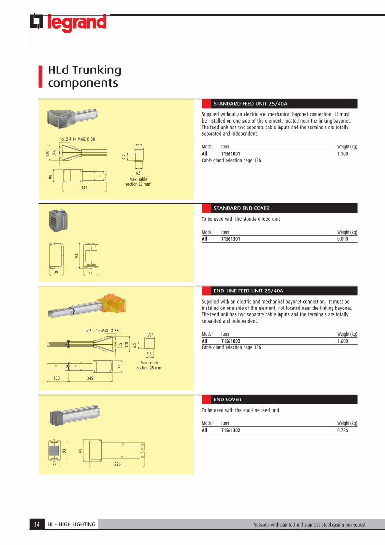
STANDARD FEED UNIT
Supplied without an electric and mechanical bayonet connection. It must be installed on one side of the element, located near the linking bayonet.
Model Item Weight (kg)LB 252 70161001 0.400LB 402 70181001 0.430LB 254 70161001 0.400LB 404 70181001 0.430For cable glands see page 136
Max. cable section 25 mm2
6.5
6.5
310
d 1= MAX. Ø 38
8060
35
STANDARD END COVER
To be used with standard feed units.
Model Item Weight (kg)All 70101351 0.060
Versions with painted and Aluminum casing on request
35
66
10 LB - LIGHTING BUSWAY
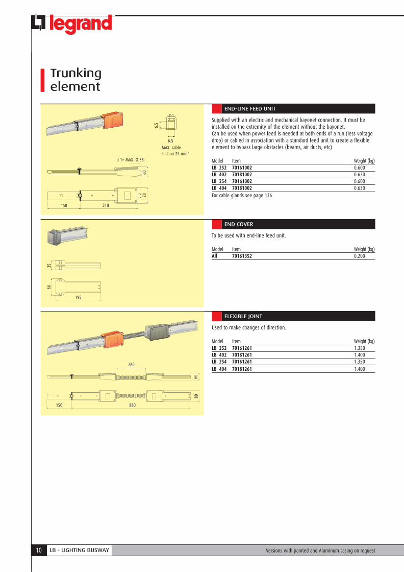
Trunking element
END-LINE FEED UNIT
Supplied with an electric and mechanical bayonet connection. It must be installed on the extremity of the element without the bayonet.Can be used when power feed is needed at both ends of a run (less voltage drop) or cabled in association with a standard feed unit to create a flexible element to bypass large obstacles (beams, air ducts, etc)
Model Item Weight (kg)LB 252 70161002 0.600LB 402 70181002 0.630LB 254 70161002 0.600LB 404 70181002 0.630For cable glands see page 136
Versions with painted and Aluminum casing on request
310150
8060
d 1= MAX. Ø 38
MAX. cable section 25 mm2
6.5
6.5
195
6635
END COVER
To be used with end-line feed unit.
Model Item Weight (kg)All 70161352 0.200
FLEXIBLE JOINT
Used to make changes of direction.
Model Item Weight (kg)LB 252 70161261 1.350LB 402 70181261 1.400LB 254 70161261 1.350LB 404 70181261 1.400
880150
8060
260

11CATALOGUE
CATALOGO CONDOTTI SBARRELOW-MEDIUM POWER GENERAL CATALOGUE
LBLI
GHTI
NG B
USW
AY
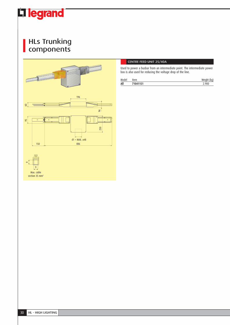
CENTRE FEED UNIT 25/40A
Used to power a busbar straight element from any intermediate point. The centre feed unit is also used for reducing the voltage drop of the line.
Model Item Weight (kg)All 70181151 2.100
Max. cable section 35 mm2
9
9
150 816
19680
250
60
96
Versions with painted and Aluminum casing on request
d1 = MAX. ø48
12 LB - LIGHTING BUSWAY
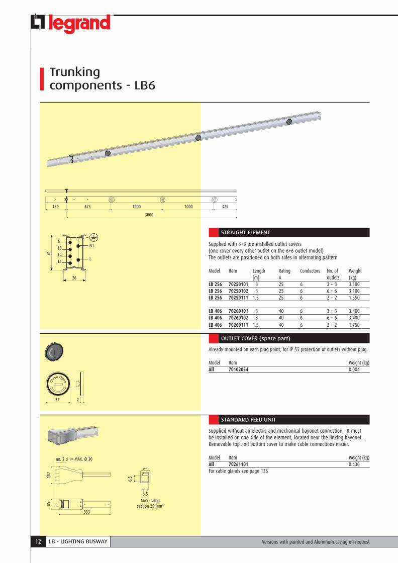
Trunkingcomponents - LB6
STRAIGHT ELEMENT
Supplied with 3+3 pre-installed outlet covers (one cover every other outlet on the 6+6 outlet model)The outlets are positioned on both sides in alternating pattern
Model Item Length Rating Conductors No. of Weight [m] A outlets (kg)LB 256 70250101 3 25 6 3 + 3 3.100LB 256 70250102 3 25 6 6 + 6 3.100LB 256 70250111 1.5 25 6 2 + 2 1.550
LB 406 70260101 3 40 6 3 + 3 3.400LB 406 70260102 3 40 6 6 + 6 3.400LB 406 70260111 1.5 40 6 2 + 2 1.750
CloseOpen
CloseOpen
CloseOpen
CloseOpen
CloseOpen
CloseOpen
150 675 1000
3000
1000 325
26
N1
L
41
N
L3
L2
L1
CloseOpen
CloseOpen
37 2
MAX. cable section 25 mm2
6.5
6.5
333
6510
7
no. 2 d 1= MAX. Ø 30
OUTLET COVER (spare part)
Already mounted on each plug point, for IP 55 protection of outlets without plug.
Model Item Weight (kg)All 70102054 0.004
STANDARD FEED UNIT
Supplied without an electric and mechanical bayonet connection. It must be installed on one side of the element, located near the linking bayonet. Removable top and bottom cover to make cable connections easier.
Model Item Weight (kg)All 70261101 0.430For cable glands see page 136
Versions with painted and Aluminum casing on request

13CATALOGUE
CATALOGO CONDOTTI SBARRELOW-MEDIUM POWER GENERAL CATALOGUE
LBLI
GHTI
NG B
USW
AY
STANDARD END COVER
To be used with standard feed units.
Model Item Weight (kg)All 70101351 0.080
MAX. cable section 25 mm2
6.5
6.5
333150
107
65
No. 2 d 1= MAX. Ø 30
926
260
150
6510
7
END-LINE FEED UNIT
Supplied with an electric and mechanical bayonet connection. It must be installed on the extremity of the element without the bayonet.Can be used when power feed is needed at both ends of a run (less voltage drop) or cabled in association with a standard feed unit to create a flexible element to bypass large obstacles (beams, air ducts, etc) Removable top and bottom cover to make cable connections easier.
Model Item Weight (kg)All 70261102 0.600For cable glands see page 136
END COVER
To be used with end-line feed unit.
Model Item Weight (kg)All 70263102 0.130
FLEXIBLE JOINT
Used to make changes of direction or avoid columns, obstructions or anything located along the path of the line.
Model Item Weight (kg)All 70263201 1.350
35
195
6635
Versions with painted and Aluminum casing on request
35
66
14 LB - LIGHTING BUSWAY
Plugs for all versions
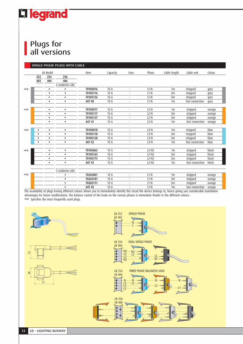
SINGLE-PHASE PLUGS WITH CABLE
LB Model Item Capacity Fuse Phase Cable length Cable end Colour 252 254 256 402 404 406 4 conductors side • • 70105016 10 A - L1-N 1m stripped grey • • 70105116 10 A - L1-N 3m stripped grey • • 70105126 10 A - L1-N 5m stripped grey • • 447 40 10 A - L1-N 1m fast connection grey • • 70105017 10 A - L2-N 1m stripped orange • • 70105117 10 A - L2-N 3m stripped orange • • 70105127 10 A - L2-N 5m stripped orange • • 447 41 10 A - L2-N 1m fast connection orange • • • 70105018 10 A - L3-N 1m stripped blue • • • 70105118 10 A - L3-N 3m stripped blue • • • 70105128 10 A - L3-N 5m stripped blue • • • 447 42 10 A - L3-N 1m fast connection blue
• • 70105063 10 A - L2-N2 1m stripped black • • 70105163 10 A - L2-N2 3m stripped black • • 70105173 10 A - L2-N2 5m stripped black • • 447 43 10 A - L2-N2 1m fast connection black 2 conductors side • 70265001 10 A - L1-N 1m stripped orange • 70265101 10 A - L1-N 3m stripped orange • 70265111 10 A - L1-N 5m stripped orange • 447 45 10 A - L1-N 1m fast connection orangeThe availability of plugs having different colours allows you to immediately identify the circuit the device belongs to, hence giving you considerable installation advantages for future modifications. The balance control of the loads on the various phases is immediate thanks to the different colours.
Specifies the most frequently used plugs.
77
5238
N
L1
N
L2
N3L3
N3L3L2N2
NL3L2L1
NL3
L2N2
LB 252LB 402
SINGLE-PHASE
DUAL SINGLE-PHASE
THREE-PHASE BALANCED LOAD
LB 254LB 404
LB 254LB 404
LB 256LB 406
NL
15CATALOGUE
CATALOGO CONDOTTI SBARRELOW-MEDIUM POWER GENERAL CATALOGUE
LBLI
GHTI
NG B
USW
AY
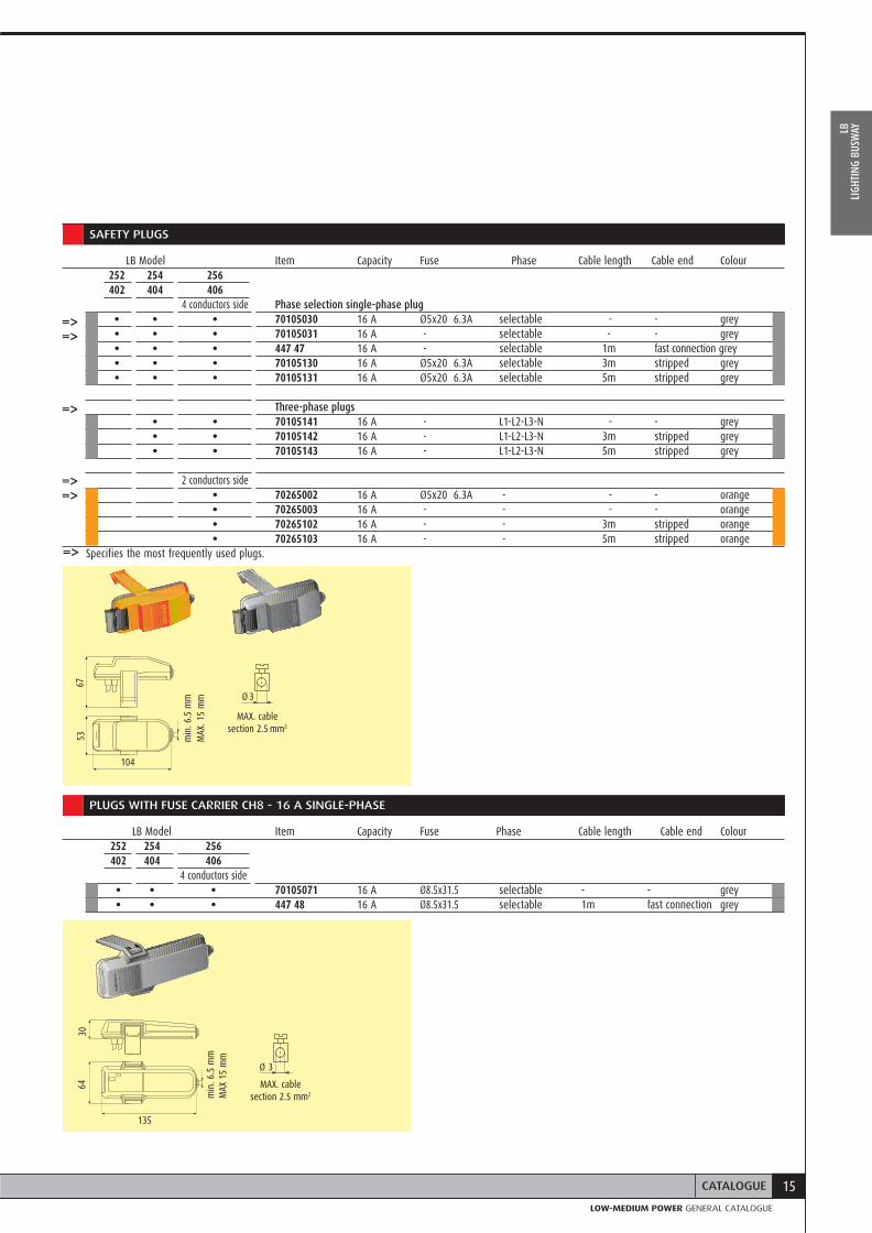
SAFETY PLUGS
LB Model Item Capacity Fuse Phase Cable length Cable end Colour 252 254 256 402 404 406 4 conductors side Phase selection single-phase plug • • • 70105030 16 A Ø5x20 6.3A selectable - - grey • • • 70105031 16 A - selectable - - grey • • • 447 47 16 A - selectable 1m fast connection grey • • • 70105130 16 A Ø5x20 6.3A selectable 3m stripped grey • • • 70105131 16 A Ø5x20 6.3A selectable 5m stripped grey Three-phase plugs • • 70105141 16 A - L1-L2-L3-N - - grey • • 70105142 16 A - L1-L2-L3-N 3m stripped grey • • 70105143 16 A - L1-L2-L3-N 5m stripped grey
2 conductors side • 70265002 16 A Ø5x20 6.3A - - - orange • 70265003 16 A - - - - orange • 70265102 16 A - - 3m stripped orange • 70265103 16 A - - 5m stripped orange
Specifies the most frequently used plugs.
104
6753 m
in. 6
.5 m
mM
AX. 1
5 m
m
MAX. cable section 2.5 mm2
Ø 3
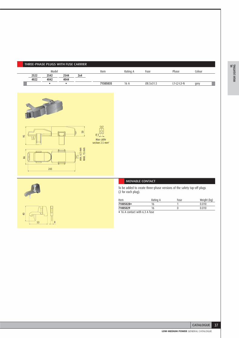
PLUGS WITH FUSE CARRIER CH8 - 16 A SINGLE-PHASE
LB Model Item Capacity Fuse Phase Cable length Cable end Colour 252 254 256 402 404 406 4 conductors side • • • 70105071 16 A Ø8.5x31.5 selectable - - grey • • • 447 48 16 A Ø8.5x31.5 selectable 1m fast connection grey
MAX. cable section 2.5 mm2
Ø 3
135
3064
min
. 6.5
mm
MAX
15
mm
16 LB - LIGHTING BUSWAY
Plugs for all versions
PLUGS WITH FUSE CARRIER - 16 A THREE-PHASE
LB Model Item Capacity A Fuse Phase Cable length Cable end Colour 252 254 256 402 404 406 4 conductors side
• • 70105035 16 A Ø 8.5x31.5* L1-L2-L3-N - - grey • • 70105045 16 A Ø 6.3x31.5* L1-L2-L3-N - - grey
• • 447 49 16 A Ø 8.5x31.5 L1-L2-L3-N 1 m fast connection grey * Fuse not included
Max. cable section 2.5 mm2
Ø 3
243
85
50
74
min
. 6.5
mm
Max
. 15
mm
MOBILE CONTACT
Can be used to transform a single phase selection plug into a three-phase plug
Item Capacity A Fuse Weight (kg)71005028** 16 A 1 0.00871005029 16 A 0 0.008 ** 16 A contact with 6.3 A ceramic fuse For fuse features, see page 136
53
40
8

17CATALOGUE
CATALOGO CONDOTTI SBARRELOW-MEDIUM POWER GENERAL CATALOGUE
LBLI
GHTI
NG B
USW
AY
Fixing supports
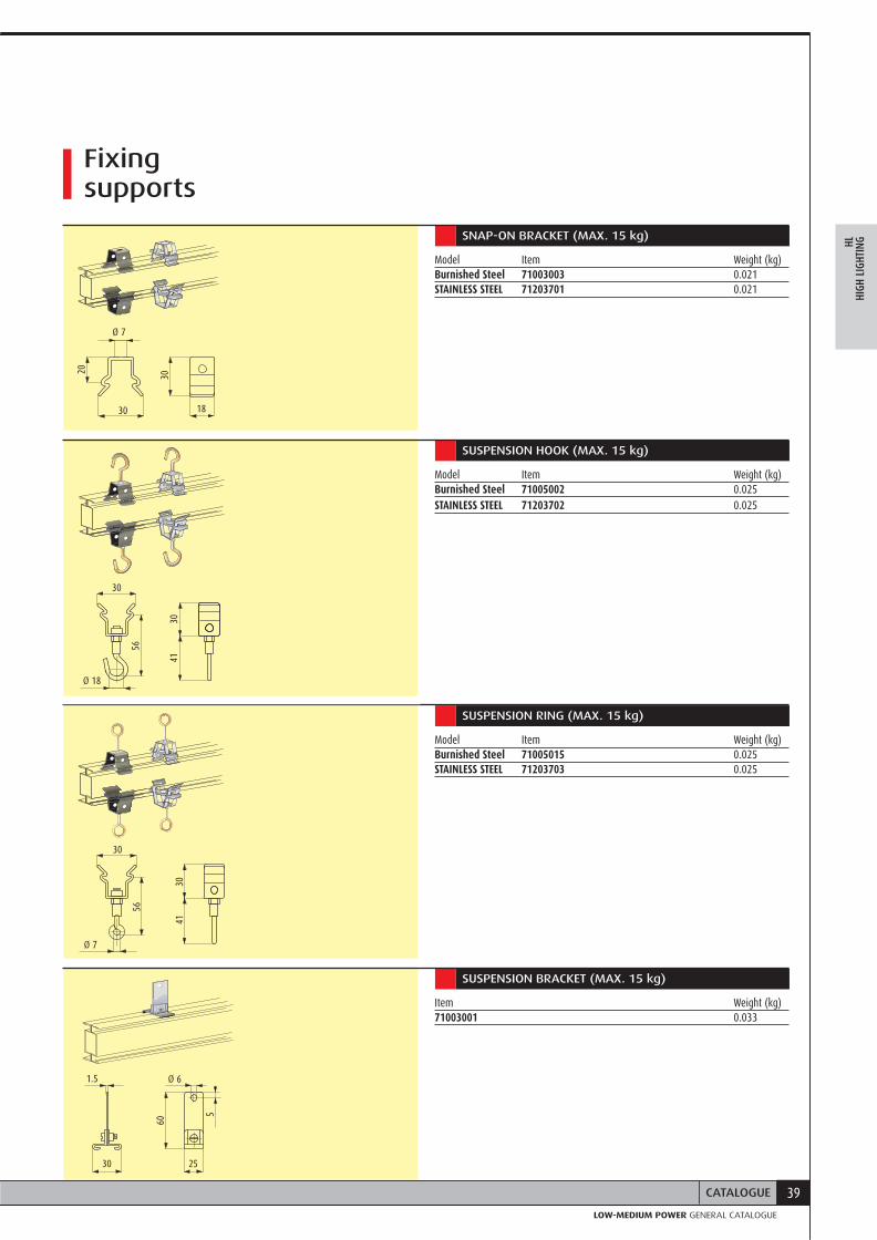
SNAP-ON BRACKET (MAX. 15 KG)
Clamp to be clipped onto the element’s top or bottom edge.
Model Item Weight (kg)Burnished Steel 71003003 0.021STAINLESS STEEL 71203701 0.021
18
30
Ø 7
Ø 18
3041
SUSPENSION HOOK (MAX. 15 kg)
Ø 7
3041
Clamp to be clipped onto the element’s top or bottom edge.
Model Item Weight (kg)Burnished Steel 71005002 0.025STAINLESS STEEL 71203702 0.025
5
60
1.5 Ø 6
SUSPENSION RING (MAX. 15 kg)
Clamp to be clipped onto the element’s top or bottom edge.
Model Item Weight (kg)Burnished Steel 71005015 0.025STAINLESS STEEL 71203703 0.025
SUSPENSION BRACKET (MAX. 15 kg)
Clamp to be clipped onto the element’s top or bottom edge.
Item Weight (kg)71003001 0.033
20
30
56
30
56
30
2530
18 LB - LIGHTING BUSWAY
Fixing elements
BRACKET HOLDER
Must be used with code 71003001 suspension bracket.
Item Weight (kg)73003312 0.136
40
250
55
20
53
35
49
27
Ø 8
Ø 6
Ø 6
55
67
49
Ø 4
.2
650
Ø 10
slot 8 x 25
WALL SUSPENSION BRACKET
Cannot be used with LB6 (no access to back side for plugs)
Item Weight (kg)71003008 0.030
BRACKET FOR COUPLING ELEMENTS
Bracket suitable for positioning two lines in parallel. The reduced dimensions are also specified for floor installations.
Item Weight (kg)70105043 0.060
Item 71003008
Item 71003008
suspension hole with chain/cable
Hole for threaded bar
floor-fixing hole
49
slot 6.5 x 8
3010
66
40
19CATALOGUE
CATALOGO CONDOTTI SBARRELOW-MEDIUM POWER GENERAL CATALOGUE
LBLI
GHTI
NG B
USW
AY
Cable channel and accessories
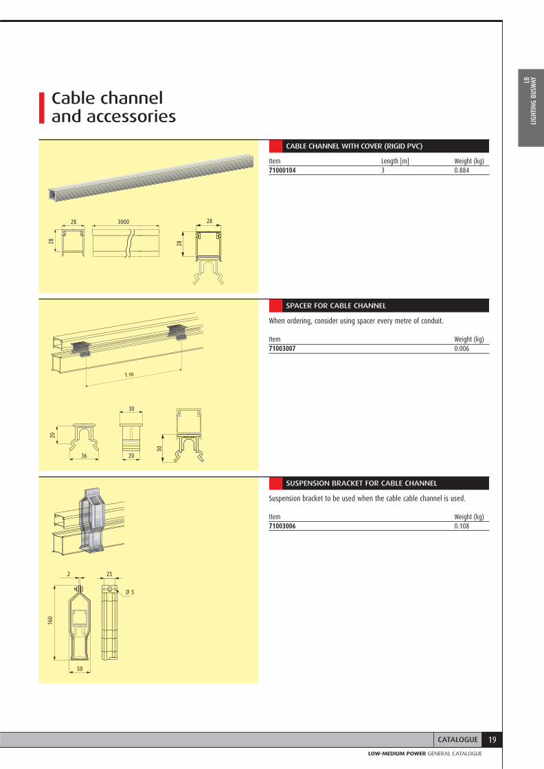
CABLE CHANNEL WITH COVER (RIGID PVC)
Item Length [m] Weight (kg)71000104 3 0.884
28 3000
28
28
SPACER FOR CABLE CHANNEL
When ordering, consider using spacer every metre of conduit.
Item Weight (kg)71003007 0.006
20
50
2 25
Ø 5
160
30
20
30
1 m
SUSPENSION BRACKET FOR CABLE CHANNEL
Suspension bracket to be used when the cable cable channel is used.
Item Weight (kg)71003006 0.108
28
36
20
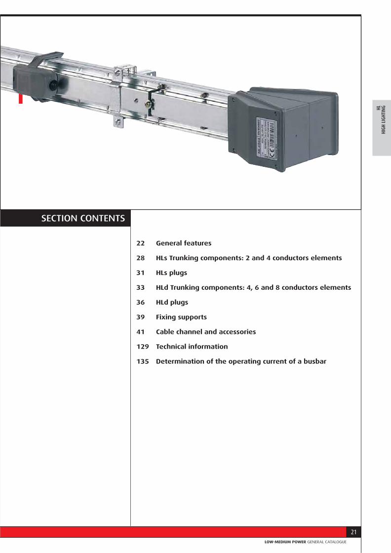
HL - HIGH LIGHTING 25 - 40A
21
CATALOGO CONDOTTI SBARRELOW-MEDIUM POWER GENERAL CATALOGUE
SECTION CONTENTS
22 General features
28 HLs Trunking components: 2 and 4 conductors elements
31 HLs plugs
33 HLd Trunking components: 4, 6 and 8 conductors elements
36 HLd plugs
39 Fixing supports
41 Cable channel and accessories
129 Technical information
135 Determination of the operating current of a busbar
HLHI
GH L
IGHT
ING
22 HL - HIGH LIGHTING
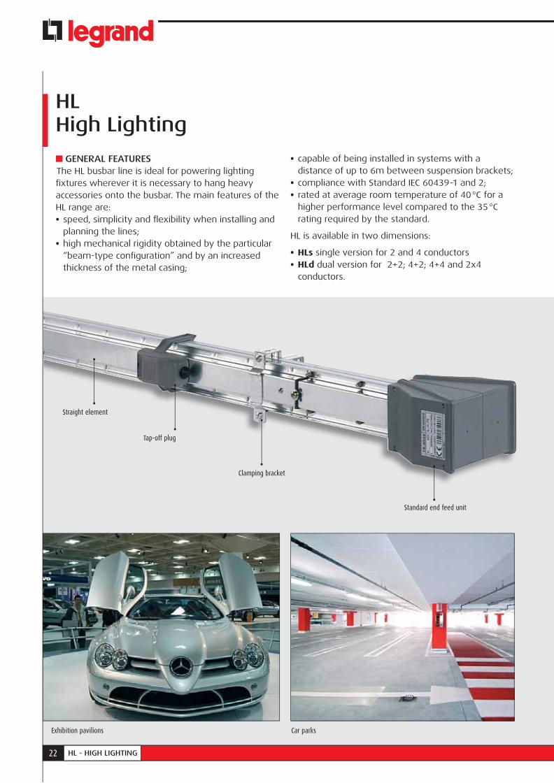
HLHigh Lighting
GENERAL FEATURESThe HL busbar line is ideal for powering lighting fi xtures wherever it is necessary to hang heavy accessories onto the busbar. The main features of the HL range are:• speed, simplicity and fl exibility when installing and
planning the lines; • high mechanical rigidity obtained by the particular
“beam-type confi guration” and by an increased thickness of the metal casing;
• capable of being installed in systems with a distance of up to 6m between suspension brackets;
• compliance with Standard IEC 60439-1 and 2;• rated at average room temperature of 40 °C for a
higher performance level compared to the 35 °C rating required by the standard.
HL is available in two dimensions:
• HLs single version for 2 and 4 conductors • HLd dual version for 2+2; 4+2; 4+4 and 2x4
conductors.
Straight element
Tap-off plug
Clamping bracket
Standard end feed unit
Exhibition pavilions Car parks

23GENERAL FEATURES
CATALOGO CONDOTTI SBARRELOW-MEDIUM POWER GENERAL CATALOGUE
HLHI
GH L
IGHT
ING
Small/medium industries Gyms
• a junction block automatically ensuring electrical continuity
The connection between two straight elements is quick; with one operation the mechanical and the electrical connection is ensured between two joined elements; at the same time, an IP 55 degree of protection is guaranteed without using additional sealing accessories. The continuity of the protective conductor (casing) is guaranteed by tightening the special connection screw. The whole busbar is fi re retardant in compliance with the Standard IEC 60332-3. In the HLd (dual) version, the straight elements are separated over their entire length by a metal plate divider (thickness 0.8 mm) which separates the straight elements in two parts making the two circuits totally independent. Because of this division the HLd busbar can be used for powering “normal” and “emergency” loads. The HLd line is designed so as to provide two separate rated circuits (25 A+25 A or 40 A+40 A) on without a derating factor, and not one one 25 or 40 A incoming divided into two circuits.
STRAIGHT ELEMENTSThe components and the features of the HL straight elements are:
• a beam-shaped casing, made with hot galvanized steel (Senzimir) (due to its cross-section and electrical continuity, it also serves as the protective earth)
• HLs busbar dimensions: 26x62 mm; HLd: 40x70 mm;• upon request, the straight elements are also
available in the Aisi 304 stainless steel version;• number of conductors: 2, 4, 6 or 8 rigid copper
conductors with a 99.9% purity; • conductor section: 3.14 mm2 for 25 A and
6.15 mm2 for 40 A;• separation between the conductors by using a V0
(according to UL94) self-extinguishing insulating plastic sheathe and in compliance with the glow-wire test according to IEC 60695-2-10;
• tap-off outlets equidistant every 1m (3 outlets every 3m) or 0.5m (6 outlets every 3m), receiving the corresponding tap-off plugs (in the LB 6 conductor version the outlets are arranged on both sides of the busbar: 3+3 or 6+6 outlets);
24 HL - HIGH LIGHTING
Fixing accessories for fastening the busbar run to the structure and hanging the lamps onto the busbar
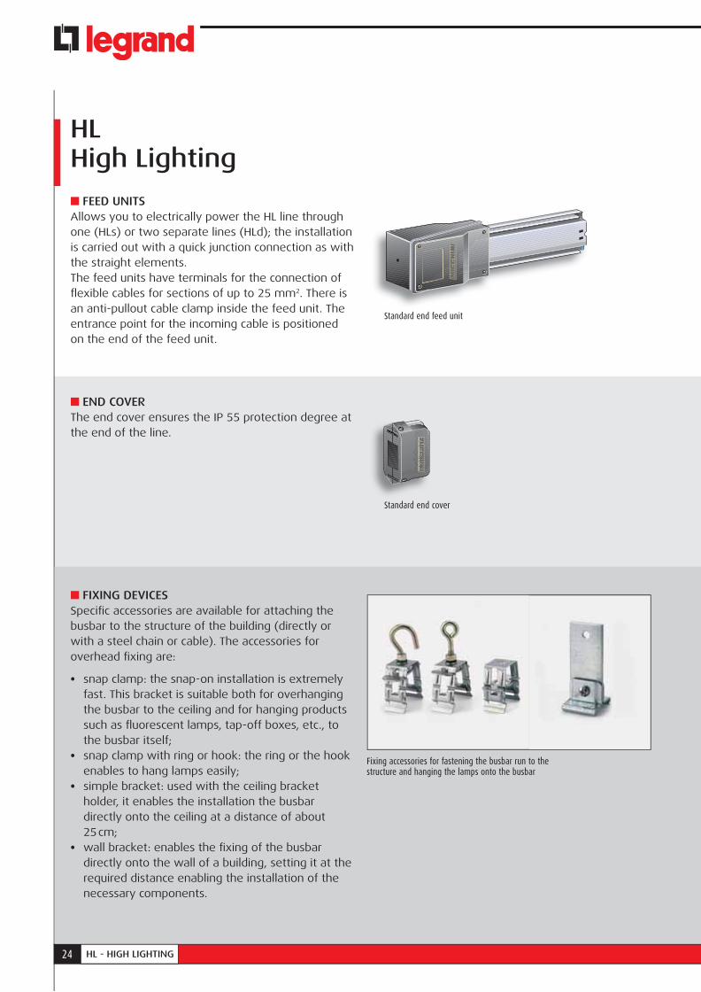
FEED UNITSAllows you to electrically power the HL line through one (HLs) or two separate lines (HLd); the installation is carried out with a quick junction connection as with the straight elements.The feed units have terminals for the connection of fl exible cables for sections of up to 25 mm2. There is an anti-pullout cable clamp inside the feed unit. The entrance point for the incoming cable is positioned on the end of the feed unit.
END COVERThe end cover ensures the IP 55 protection degree at the end of the line.
FIXING DEVICESSpecifi c accessories are available for attaching the busbar to the structure of the building (directly or with a steel chain or cable). The accessories for overhead fi xing are:
• snap clamp: the snap-on installation is extremely fast. This bracket is suitable both for overhanging the busbar to the ceiling and for hanging products such as fl uorescent lamps, tap-off boxes, etc., to the busbar itself;
• snap clamp with ring or hook: the ring or the hook enables to hang lamps easily;
• simple bracket: used with the ceiling bracket holder, it enables the installation the busbar directly onto the ceiling at a distance of about 25 cm;
• wall bracket: enables the fi xing of the busbar directly onto the wall of a building, setting it at the required distance enabling the installation of the necessary components.
HLHigh Lighting
Standard end feed unit
Standard end cover
25GENERAL FEATURES
CATALOGO CONDOTTI SBARRELOW-MEDIUM POWER GENERAL CATALOGUE
HLHI
GH L
IGHT
ING
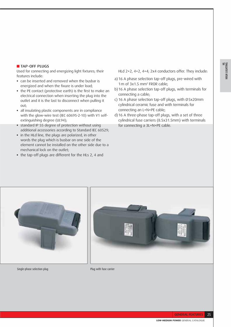
TAP-OFF PLUGSUsed for connecting and energizing light fixtures; their features include: • can be inserted and removed when the busbar is
energized and when the fixure is under load;• the PE contact (protective earth) is the first to make an
electrical connection when inserting the plug into the outlet and it is the last to disconnect when pulling it out;
• all insulating plastic components are in compliance with the glow-wire test (IEC 60695-2-10) with V1 self-extinguishing degree (UL94);
• standard IP 55 degree of protection without using additional accessories according to Standard IEC 60529;
• in the HLd line, the plugs are polarized, in other words the plug which is busbar on one side of the element cannot be installed on the other side due to a mechanical lock on the outlet;
• the tap-off plugs are different for the HLs 2, 4 and
HLd 2+2, 4+2, 4+4; 2x4 conductors offer. They include:
a) 16 A phase selection tap-off plugs, pre-wired with 1 m of 3x1.5 mm2 FROR cable;
b) 16 A phase selection tap-off plugs, with terminals for connecting a cable;
c) 16 A phase selection tap-off plugs, with Ø 5x20mm cylindrical ceramic fuse and with terminals for connecting an L+N+PE cable;
d) 16 A three-phase tap-off plugs, with a set of three cylindrical fuse carriers (8.5x31.5mm) with terminals for connecting a 3L+N+PE cable.
Single-phase selection plug Plug with fuse carrier
26 HL - HIGH LIGHTING
The end cap completes the installation of the lines and guarantees the IP 55 degree of protection of the line.
Straight elements, with tap-off outlets every 1000 mm on both sides, with pre-installed blanking accessory.
Phase selection tap-off plugs, also available with fuses.
Ring for suspending a lamp or for suspending other accessories of the busbar. (boxes, loudspeakers, etc.)
Snap-on bracket that can be used for suspending the line and devices
Hook for suspending a lamp or for suspending busbar itself and other devices (lamps, etc)
Depending on the different installation requirements Zucchini can provide various technical solutions:
a) fl exible joint: used to make changes of direction or to avoid possible interferences that may be found on the path of the busbar.
Their main technical features are: • same connection method as the straight elements; • electrical and mechanical connection with one
operation; • standard degree of protection: IP 55;• continuity of the protective conductor, made from the
casing of the element itself, guaranteed by tightening the special connection screw;
b) cable trunking with cover: this accessory, which can be positioned in the upper part of the busbar, can be used to distribute auxiliary circuits, it is an integral part of the busbar run using special spacers and brackets which support the busbar trunking system fi rmly. The trunking part is 3 m long and its dimensions are 28x28 mm;
c) intermediate feed unit: it can power the busbar from an intermediate point of the line, thus reducing the voltage drop at the end of the line and/or making the installation easier when the electric energy supply point is near the middle of the line.
Trunking components and additional elements
Single-phase selection plug Ceiling suspension bracket Plug with fuse carrier
PARTS OF THE LINE
27GENERAL FEATURES
CATALOGO CONDOTTI SBARRELOW-MEDIUM POWER GENERAL CATALOGUE
HLHI
GH L
IGHT
ING
Wall suspension bracket
Single-phase 16 A tap-off plugs with a pre-wired cable and phase identification using colours:N - L1 = greyN - L2 = orangeN - L3 = bluefor L+N circuit andN3 - L3 = blueN2 - L2 = blackfor single-phase dual circuit.
Feed units, complete with cable clamp and terminals for 25 mm2 cables.
Outlet cover (spare)Simple suspension bracket Snap-on stainless steel hook, ring and bracket
Wall mounting bracket
28 HL - HIGH LIGHTING
HL Trunking components - single
STRAIGHT ELEMENT
Elements with pre-installed outlet covers.
Model Item Length Rating Conductors No. of Weight (m) (A) outlets (kg)HL 252 71010151 3 25 2 3 4.5HL 252 71010161 1.5 25 2 2 2.25
HL 402 71030151 3 40 2 3 4.8HL 402 71030161 1.5 40 2 2 2.4
HL 254 71020151 3 25 4 3 4.8HL 254 71020161 1.5 25 4 2 2.4
HL 404 71040151 3 40 4 3 5.1HL 404 71040161 1.5 40 4 2 2.55
150
62 3812
35
25
26
N
L1
345
9560
d 1= MAX Ø 38
Max. cablesection 25 mm2
6.5
6.5
HL 252HL 402
HL 254HL 404
NL3L2L1
12
325 1000
3000
1000 675
OUTLET COVER (Spare)
The straight elements are supplied with outlet cover pre-installed on the outlets. Model Item Colour Weight (kg)All 71023601 grey 0.011
STANDARD FEED UNIT
Supplied without an electric and mechanical bayonet connection. It must be installed on one side of the element, located near the linking bayonet. Model Item Weight (kg)All 71041001 0.800For cable glands see page 136
29CATALOGUE
CATALOGO CONDOTTI SBARRELOW-MEDIUM POWER GENERAL CATALOGUE
HLHI
GH L
IGHT
INGSTANDARD END COVER
To be used with standard feed units
Model Item Weight (kg)All 71041301 0.050
3936
81
Max. cable section 25 mm2
6.5
6.5
226
81
345150
150
6095
930
240
9560
d 1= MAX. Ø 38
END-LINE FEED UNIT
Supplied with an electric and mechanical bayonet connection. It must be installed on the extremity of the element without the bayonet.Can be used when power feed is needed at both ends of a run (less voltage drop) or cabled in association with a standard feed unit to create a flexible element to bypass large obstacles (beams, air ducts, etc) Model Item Weight (kg)All 71041002 1.000
END COVER
To be used with end-line feed unit. Model Item Weight (kg)All 71041302 0.360
FLEXIBLE JOINT
Used to make changes of direction. Model Item Weight (kg)All 71041261 2.500
30 HL - HIGH LIGHTING
HLs Trunkingcomponents
CENTRE FEED UNIT 25/40A
Used to power a busbar from an intermediate point. The intermediate power box is also used for reducing the voltage drop of the line. Model Item Weight (kg)All 71041151 2.900
250
96196
9560
Max. cable section 35 mm2
9
9
150 886
d1 = MAX. ø48
31CATALOGUE
CATALOGO CONDOTTI SBARRELOW-MEDIUM POWER GENERAL CATALOGUE
HLHI
GH L
IGHT
ING
HLs plugs
104
Max cable section 2.5 mm2
Ø 3
6772 min
. 6.5
mm
MAX
. 15
mm
PHASE SELECTION SAFETY PLUGS
Model Item Rating Fuse Phase Cable length Cable end Colour 252 254 402 404 • • 71005030 16 A Ø5x20 selectable - - grey • • 71005031 16 A - selectable - - grey
• • 71005032 16 A - selectable 1m stripped grey
• 71015030 16 A Ø5x20 L1-N - - blue
Max cable section 2.5 mm2
Ø 3
135
3075 m
in. 6
.5 m
mM
AX. 1
5 m
m
SINGLE-PHASE PLUGS WITH FUSE CARRIER
Model Item Rating Fuse Phase Cable length Cable end Colour 252 254 402 404 • • 71005068 16 A Ø8.5x31.5 selectable - - grey
• • 71005070 16 A Ø8.5x31.5 L1-N 1m stripped grey • 71005071 16 A Ø8.5x31.5 L2-N 1m stripped orange • 71005072 16 A Ø8.5x31.5 L3-N 1m stripped blue
7100503071005031
HL 254HL 404grey outlet
71015030 710050307100503171005032
HL 252HL 402
blue outlet
BLUE
GREY
GREY
60
32 HL - HIGH LIGHTING
HLs plugs
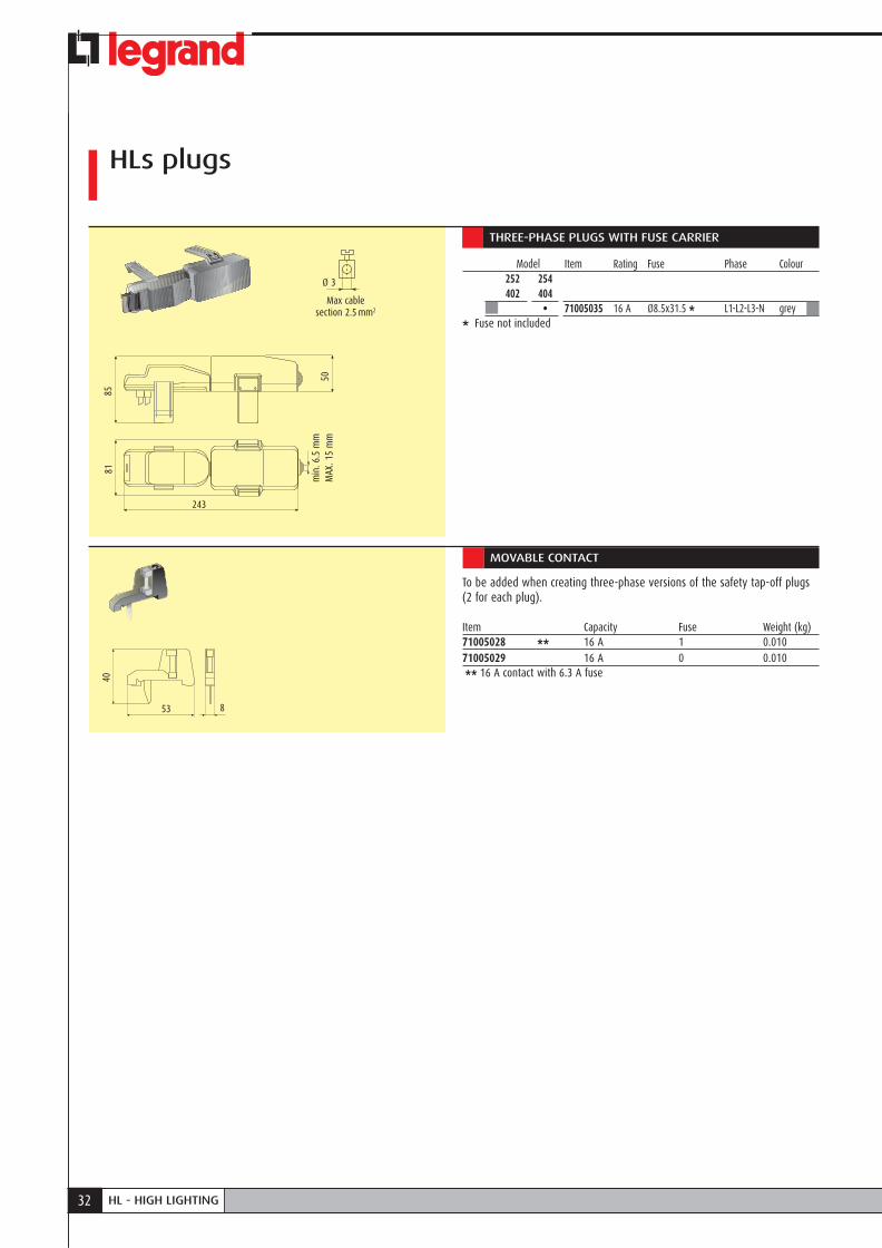
THREE-PHASE PLUGS WITH FUSE CARRIER
Model Item Rating Fuse Phase Colour 252 254 402 404 • 71005035 16 A Ø8.5x31.5 * L1-L2-L3-N grey* Fuse not included
Max cable section 2.5 mm2
Ø 3
243
85
50
81
min
. 6.5
mm
MAX
. 15
mm
MOVABLE CONTACT
To be added when creating three-phase versions of the safety tap-off plugs (2 for each plug).
Item Capacity Fuse Weight (kg)71005028 ** 16 A 1 0.01071005029 16 A 0 0.010 ** 16 A contact with 6.3 A fuse
53
40
8

33CATALOGUE
CATALOGO CONDOTTI SBARRELOW-MEDIUM POWER GENERAL CATALOGUE
HLHI
GH L
IGHT
ING
HLd Trunking components
L1L3L4L2
ZL6L5X
HL 2x4
N
L1
HL 2542HL 4042
70 3816
40
26
L1
N
NL2
HL 2522HL 4022
16
L1L2L3N
HL 2544HL 4044
NL3L2L1
HL 2x4 to create 4 interlocked single-phase circuits
STRAIGHT ELEMENT
Elements with pre-installed outlet covers.
Model Item Length Rating Conductors No. of Weight (m) (A) outlets (kg)HL 2522 71510151 3 25+25 2 + 2 6 8.4HL 2522 71510161 1.5 25+25 2 + 2 4 4.2
HL 4022 71540151 3 40+40 2 + 2 6 8.7HL 4022 71540161 1.5 40+40 2 + 2 4 4.35
HL 2542 71520151 3 25+25 4 + 2 6 8.7HL 2542 71520161 1.5 25+25 4 + 2 4 4.35
HL 4042 71550151 3 40+40 4 + 2 6 9.3HL 4042 71550161 1.5 40+40 4 + 2 4 4.65
HL 2544 71530151 3 25+25 4 + 4 6 8.7HL 2544 71530161 1.5 25+25 4 + 4 4 4.35
HL 4044 71560151 3 40+40 4 + 4 6 9.6HL 4044 71560161 1.5 40+40 4 + 4 4 4.8
HL 2x4 71570151 3 25+25 2+2+2+2 6 8.7HL 2x4 71570161 1.5 25+25 2+2+2+2 4 4.35
L1L2L3N
150 325 1000
3000
1000 675
OUTLET COVER (spare)
The elements are supplied with outlet covers pre-installed on the outlet covers.
Model Item Colour Weight (kg)All 01150048 grey 0.011
35
25
Versions with painted and stainless steel casing on request
34 HL - HIGH LIGHTING
HLd Trunking components
STANDARD FEED UNIT 25/40A
Supplied without an electric and mechanical bayonet connection. It must be installed on one side of the element, located near the linking bayonet. The feed unit has two separate cable inputs and the terminals are totally separated and independent.
Model Item Weight (kg)All 71561001 1.100Cable gland selection page 136
Max. cable section 25 mm2
39
6.5
6.5
Max. cable section 25 mm2
345150
95
120
55
no.2 d 1= MAX. Ø 38
6.5
6.5
345
9512
0 55
no. 2 d 1= MAX. Ø 38
STANDARD END COVER
To be used with the standard feed unit
Model Item Weight (kg)All 71561301 0.090
END-LINE FEED UNIT 25/40A
Supplied with an electric and mechanical bayonet connection. It must be installed on one side of the element, not located near the linking bayonet. The feed unit has two separate cable inputs and the terminals are totally separated and independent.
Model Item Weight (kg)All 71561002 1.600Cable gland selection page 136
END COVER
To be used with the end-line feed unit.
Model Item Weight (kg)All 71561302 0.786
Versions with painted and stainless steel casing on request
55
9393
22655
93

35CATALOGUE
CATALOGO CONDOTTI SBARRELOW-MEDIUM POWER GENERAL CATALOGUE
HLHI
GH L
IGHT
INGFLEXIBLE JOINT 25/40A
Used to make changes of direction.
Model Item Weight (kg)All 71561261 3.000
150
120
95
930
240
CENTRE FEED UNIT 25/40A
Used to power a busbar from an intermediate point. The intermediate power box is also used for reducing the voltage drop of the line.
Model Item Weight (kg)All 71561151 3.800
886150
*
250
196
9519
2
Max. cable section 35 mm2
9
9
Versions with painted and stainless steel casing on request
max 2 holes ø 48mm

36 HL - HIGH LIGHTING
HLd plugs
HLd PLUGS
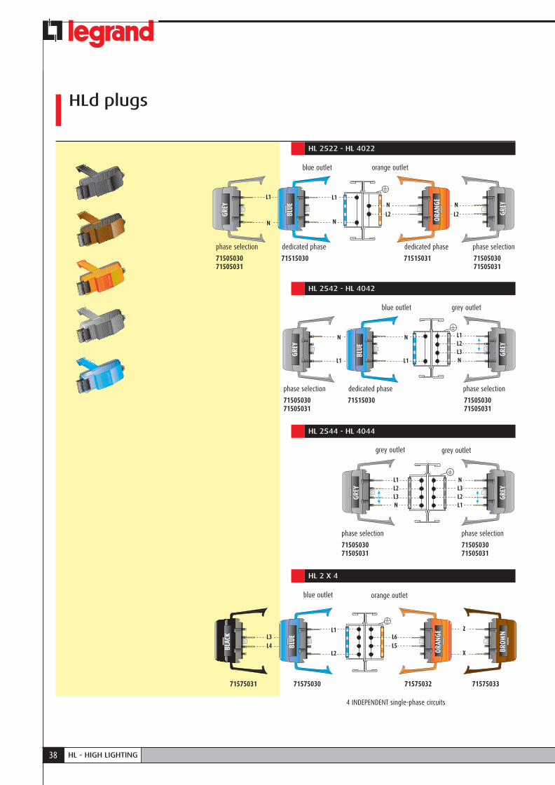
Model Item Rating Fuse Phase Cable length Cable end Colour 2522 2542 2544 2x4 4022 4042 4044 • • • • 71505030 16 A Ø5x20 selectable - - grey • • • • 71505031 16 A - selectable - - grey
• • • • 71505032 16 A - selectable 1m stripped grey • • 71515030 16 A Ø5x20 L1-N - - blue • 71515031 16 A Ø5x20 L2-L3 - - orange • 71575030 16 A Ø5x20 L1-L2 - - blue • 71575031 16 A Ø5x20 L3-L4 - - black • 71575032 16 A Ø5x20 L5-L6 - - orange • 71575033 16 A Ø5x20 X-Z - - brown
Specifies the most frequently used plugs.
104
Max cable section 2.5 mm2
Ø 3
7781 m
in. 6
.5 m
mM
AX. 1
5 m
m
SINGLE-PHASE PLUGS WITH CH8 FUSE CARRIER
Model Item Rating Fuse Phase Cable length Cable end Colour 2522 2542 2544 2x4 4022 4042 4044 • • • • 71505059 16 A Ø8.5x31.5 selectable - - grey • • 71505070 16 A Ø8.5x31.5 L1-N 1m stripped grey • • 71505071 16 A Ø8.5x31.5 L2-N 1m stripped orange • • 71505072 16 A Ø8.5x31.5 L3-N 1m stripped blue
Max cable section 2.5 mm2
Ø 3
135
3080 m
in. 6
.5 m
mM
AX. 1
5 m
m
70
37CATALOGUE
CATALOGO CONDOTTI SBARRELOW-MEDIUM POWER GENERAL CATALOGUE
HLHI
GH L
IGHT
INGTHREE-PHASE PLUGS WITH FUSE CARRIER
Model Item Rating A Fuse Phase Colour 2522 2542 2544 2x4 4022 4042 4044 • • 71505035 16 A Ø8.5x31.5 L1-L2-L3-N grey
MOVABLE CONTACT
To be added to create three-phase versions of the safety tap-off plugs (2 for each plug).
Item Rating A Fuse Weight (kg)71005028* 16 1 0.01071005029 16 0 0.010* 16 A contact with 6.3 A fuse
Max cable section 2.5 mm2
243
95
50
53
40
8
86
min
. 6.5
mm
MAX
. 15
mm
Ø 3
38 HL - HIGH LIGHTING
HLd plugs
HL 2522 - HL 4022
7150503071505031
71515030 71515031 7150503071505031
blue outlet
phase selection phase selectiondedicated phase dedicated phase
orange outlet
L1
N
L1
N
N
L2
N
L2BLUE
ORAN
GE
GREY
GREY
HL 2542 - HL 4042
7150503071505031
phase selection
7150503071505031
phase selection
71515030
dedicated phase
blue outlet grey outlet
BLUE
GREY
GREY
N
L1
N
L1
L1L2L3 N
HL 2544 - HL 4044
7150503071505031
phase selection
7150503071505031
phase selection
grey outlet grey outlet
GREY
GREY
L1L2L3 N
NL3L2 L1
HL 2 X 4
71575031 71575030 71575032 71575033
blue outlet orange outlet
4 INDEPENDENT single-phase circuits
BROW
N
ORAN
GE
BLUE
BLAC
K
L1
L2
L3 L4
L6 L5
Z
X
39CATALOGUE
CATALOGO CONDOTTI SBARRELOW-MEDIUM POWER GENERAL CATALOGUE
HLHI
GH L
IGHT
ING
Fixing supports
SNAP-ON BRACKET (MAX. 15 kg)
Model Item Weight (kg)Burnished Steel 71003003 0.021STAINLESS STEEL 71203701 0.021
18
30
Ø 7
Ø 18
3041
SUSPENSION HOOK (MAX. 15 kg)
3041
Ø 7
25
5
60
1.5 Ø 6
Model Item Weight (kg)Burnished Steel 71005002 0.025STAINLESS STEEL 71203702 0.025
SUSPENSION RING (MAX. 15 kg)
Model Item Weight (kg)Burnished Steel 71005015 0.025STAINLESS STEEL 71203703 0.025
SUSPENSION BRACKET (MAX. 15 kg)
Item Weight (kg)71003001 0.033
30
20
56
30
56
30
30

40 HL - HIGH LIGHTING
Fixing elements
WALL SUSPENSION BRACKET
For wall mounting of the HLd elements, it is possible to connect the plug on the internal side only if the busbar is taken out of the wall bracket, then insert the plug and replace the element afterwards.
Item Weight (kg)71003009 0.090
13 x
6.5
2555
250
55
96 55
46
500
slot 5 x 12
67
Ø 4
.2
6
50
Ø 10
7796
55
77
96
13 x
6.5
25
CEILING BRACKET HOLDER
Must be used with the code 71003001 suspension bracket.
Item Weight (kg)73003312 0.136
FLOOR FIXING BRACKET
Only for the HLs single version. Suitable for horizontal HLs floor fastening.
Item Weight (kg)71003018 0.090Compatible with:HL 252, HL 402, HL 254, HL 404
JUNCTION STIFFENER
To be used for strengthening bracket links with suspension centre distances that are over 5m.
Model Item Weight (kg)for single-type 71042024 0.200for dual-type 71042025 0.200
40
80
40
40
49
slot 8 x 25
69
41CATALOGUE
CATALOGO CONDOTTI SBARRELOW-MEDIUM POWER GENERAL CATALOGUE
HLHI
GH L
IGHT
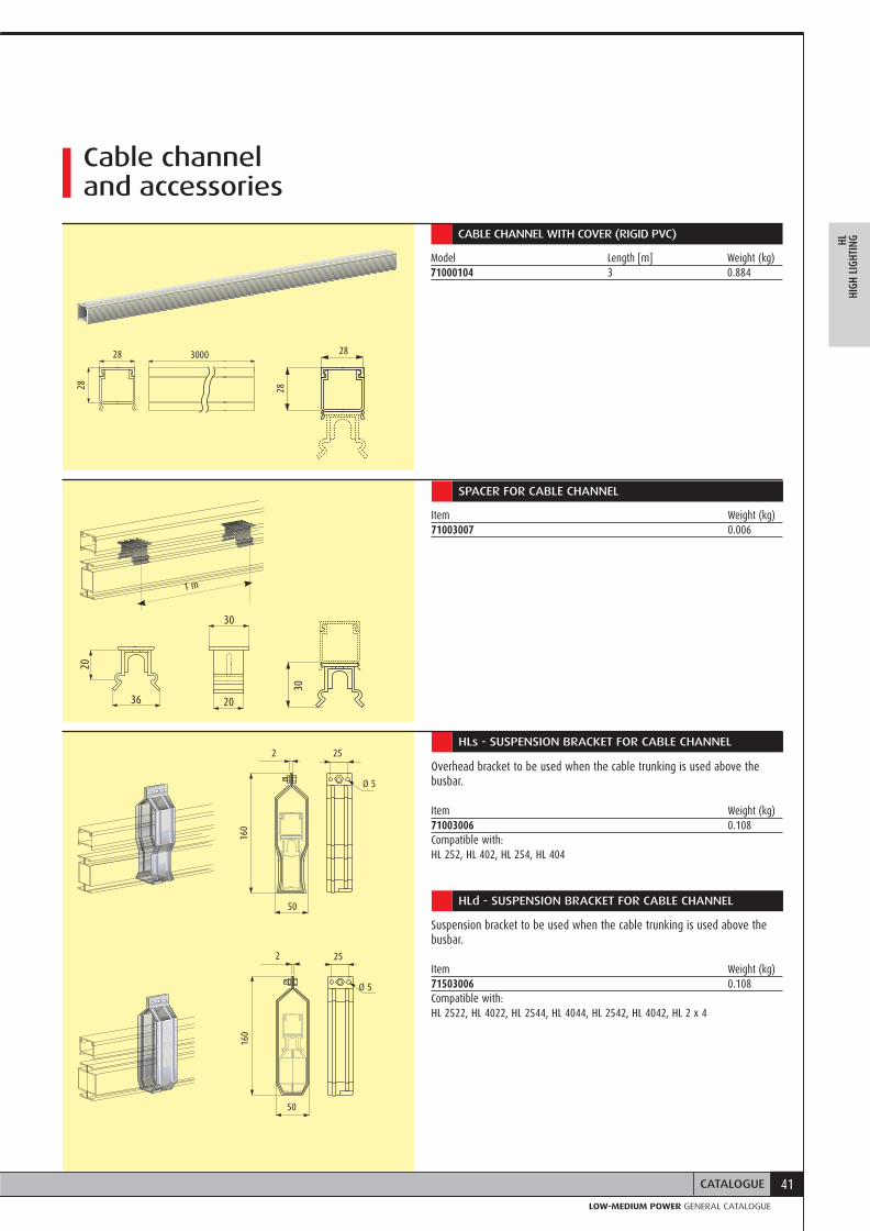
INGCABLE CHANNEL WITH COVER (RIGID PVC)
Model Length [m] Weight (kg)71000104 3 0.884
Cable channel and accessories
36
20
20
30
30
28 3000
28
25
Ø 5
50
2 25
Ø 5
160
2
50
160
1 m
SPACER FOR CABLE CHANNEL
Item Weight (kg)71003007 0.006
HLs - SUSPENSION BRACKET FOR CABLE CHANNEL
Overhead bracket to be used when the cable trunking is used above the busbar.
Item Weight (kg)71003006 0.108Compatible with:HL 252, HL 402, HL 254, HL 404
HLd - SUSPENSION BRACKET FOR CABLE CHANNEL
Suspension bracket to be used when the cable trunking is used above the busbar.
Item Weight (kg)71503006 0.108Compatible with:HL 2522, HL 4022, HL 2544, HL 4044, HL 2542, HL 4042, HL 2 x 4
28
28

4242
SL - SERIE LUCE40 - 63A

43
CATALOGO CONDOTTI SBARRELOW-MEDIUM POWER GENERAL CATALOGUE
43
SECTION CONTENTS
44 General features
50 Trunking components
52 Plugs and tap-off boxes
53 Fixing supports
55 Cable channel and accessories
130 Technical information
135 Determination of the operating current of a busbar
LOW-MEDIUM POWER GENERAL CATALOGUE
SLLI
GHT
SERI
ES
44 SL - SERIE LUCE
GENERAL FEATURESThe Zucchini SL line is suitable for powering small one-phase and three-phase equipment, such as: industrial refrigerators, lathes, hand tools, etc. The main features of the SL range are:
• speed, simplicity and fl exibility when installing and planning the lines;
• reduced dimensions;• a rigid and robust structural design for severe
installation conditions;• tap-off boxes with possibility of local protection
with mcbs (Legrand Lexic series);• capable of being installed in systems with a bracket
centre distance of up to 6m;• compliance with Standard IEC 60439-1 and 2;• rated at average room temperature of 40°C for a
higher performance level compared to the 35°C rating required by the standard.
SLSerie Luce
Straight element
Tap-off box
Feed unit
Shopping centres
Small industries
45GENERAL FEATURES
CATALOGO CONDOTTI SBARRELOW-MEDIUM POWER GENERAL CATALOGUE
SLLI
GHT
SERI
ES
STRAIGHT ELEMENTSThe components and the features of the SL straight elements are:
• a “beam-shaped” section, made with hot galvanized steel (Senzimir) which, thanks to its section and electrical continuity, can also serve as a protective conductor;
• casing thickness: 0.8mm;• busbar dimensions: 26x62mm;• number of conductors: 4 copper conductors with
purity no less than 99.9%; section of conductors: 9.5 mm2 per In 40A and 12.3 mm2 per In 63A;
• separation between the conductors by using a V0 self-extinguishing insulating plastic sheathe (according to UL94) and in compliance with the glow-wire test according to IEC 60695-2-10;
• tap-off outlets (IP40/IP 55) with a centre distance of 0.75 m (4 outlets every 3m), set up for being connected with plugs and/or tap-off boxes;
• an electrical joint block for automatically connecting live parts.
The connection between two straight elements is quick; with one operation the electric and a mechanical connection is easily made. The IP40 performance of the SL line can be easily upgraded to IP 55 with joint covers and outlet covers. The continuity of the protective earth is automatically ensured when two components are joined. The whole busbar is fi re retardant in compliance with the IEC 60332-3 standard. There are also 3m straight elements with 6 or 10 tap-off outlets. These versions, which are characterized by high density junction points, are particularly valued in fl oating underfl oor installations or when distributing energy on board the machine.
Power lines
Light lines
46 SL - SERIE LUCE
Fixing accessories for fastening the busbar run to the structure and hanging the lamps onto the busbar
FEED UNITSThe feed unit is assembled to the run in an identical manner as with the straight elements. The feed units have terminals for the connection of copper cables for sections of up to 25 mm².There is an anti-pullout cable clamp jumper insidethe power supply. The entrance point of the cables ispositioned on the end of the feed unit.
END COVERThe end cover ensures the IP 55 protection degree at the end of the line.
FIXING SUPPORTSSpecifi c accessories are available for fi xing the line to the structure of the building (directly or with a steel chain or cable). The accessories for overhead fi xing are:
• snap clamp: the snap-on installation is extremely fast. This bracket is suitable both for overhanging the busbar to the ceiling and for hanging products such as fl uorescent lamps, tap-off boxes, etc., to the busbar itself;
• snap clamp with ring or hook: the ring or the hook enables to hang lamps easily;
• simple bracket: used with the ceiling bracket holder, it enables the installation the busbar directly onto the ceiling at a distance of about 25cm;
• wall bracket: enables the fi xing of the busbar directly onto the wall of a building, setting it at the required distance enabling the installation of the necessary components.
SLSerie Luce
Feed unit
End cover

47GENERAL FEATURES
CATALOGO CONDOTTI SBARRELOW-MEDIUM POWER GENERAL CATALOGUE
SLLI
GHT
SERI
ES
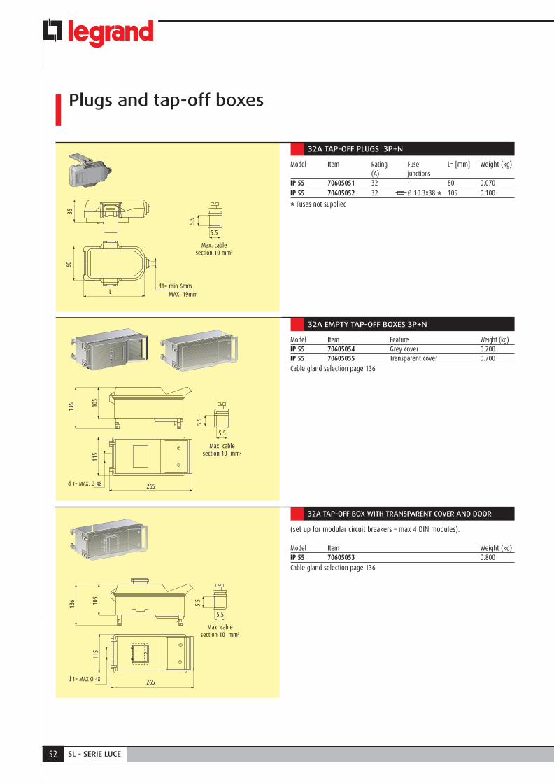
PLUGS AND TAP-OFF BOXES Used for connecting and energizing small single and three-phase loads; their features include:
• manoeuvrability when energized;• the PE contact (protective earth) is the first to make
an electrical connection when inserting the plug into the outlet and it is the last to disconnect when pulling it out;
• all insulating plastic components are in compliance with the glow-wire test (IEC 60695-2-10) with V1 self-extinguishing degree (UL94);
• IP 55 according to Standard IEC 60529, with no additional accessories.
Tap-off plugs are three-phase, 32A plugs available in two versions; without fuse or with 10.3 x 38mm fuse carriers.
Tap-off boxes allow local protection of the derivation using the Legrand Lexic DIN rail mounting mcbs.The following are available:a) 32A empty tap-off boxes with a disconnection
system integrated into the cover: when the cover is opened the power is automatically disconnected from all the accessible metal parts;
b) 32A tap-off box with a 4 module DIN window: In these boxes, the window allows the possibility of operating the Lexic DIN rail modules without opening the cover.
Tap-off box

48 SL - SERIE LUCE
Depending on the different installation requirements Zucchini can provide various technical solutions:
a) Flexible joint: used to make changes of direction or to avoid possible interferences that may be found on the natural path of the busbar. The features are as follows:
• same connection method as the straight elements;• electrical and mechanical connection with one
operation;• degree of basic protection IP40 (IP 55 with joint
covers and outlet covers);
• continuity of the protective conductor, made from the casing of the element itself, guaranteed by tightening the special connection screw;
b) cable trunking with cover: this accessory, which can be positioned on the upper or lower part of the busbar, can be used to distribute auxiliary circuits. It is an integral part of the busbar by using special spacers and brackets which hold the busbar trunking system fi rmly.
Trunking components and additional elements
Tap-off box Flexible joint
PARTS OF THE LINE
The end cover completes the installation of the lines and guarantees the degree of protection of the line.
Ring clamp for hanging lighting or suspension of the busbar with chain or wire cable.
32A tap-off boxes with transparent cover for modular circuit breakers – 4 DIN modules.
Snap-on bracket.

49GENERAL FEATURES
CATALOGO CONDOTTI SBARRELOW-MEDIUM POWER GENERAL CATALOGUE
SLLI
GHT
SERI
ES
Outlet coverSimple suspension bracket Snap-on stainless steel bracketsWall mounting bracket
Straight elements with tap-off outlets every 1000 mm on one side, with pre-installed outlet covers. If required, straight elements are available with 6 junctions (every 500 mm).
32A three-phase tap-off plugs, available with a set of three fuse carriers
Standard or end-line feed units, according to the trend of the line, complete with cable clamp and terminals for 25 mm2 cables.
Overhead hook for lamps
50 SL - SERIE LUCE
Trunking components
STRAIGHT ELEMENT
Model Item Length Rating No. of Weight (kg) (m) (A) outletsSL40 70400101 3 40 4 6.200SL40 70400111 3 40 6 6.800SL40 70400112 3 40 10 7.300SL40 70600102 1.5 63 2 3.850
SL63 70600101 3 63 4 6.500SL63 70600111 3 63 6 6.900SL63 70600112 3 63 10 7.400SL63 70600102 1.5 63 2 3.850
26
3862
1212
69
216 150
95
Max. cable section 25 mm2
6.5
6.5
60
d 1= MAX Ø 38
35 42
L1NL2L3
150
475 750
3000
750 750 425
IP 55 OUTLET COVER
Item Weight (kg)71002062 0.474One cover needed per unused outlet
STANDARD FEED UNIT
Model Item Weight (kg)IP 55 70601061 0.750Cable gland selection page 136

51CATALOGUE
CATALOGO CONDOTTI SBARRELOW-MEDIUM POWER GENERAL CATALOGUE
SLLI
GHT
SERI
ES
END-LINE FEED UNIT
Model Item Weight (kg)IP 55 70601062 0.826Cable gland selection page 136
Max. cable section 25 mm2
6.5
6.5
97
56 240
150 216
9560
d 1= MAX. Ø 38
IP 55 END COVER
Ensures the IP 55 at the end of the line. Used with standard and end-line feed unit.
Item Weight (kg)71001351 0.570
97
56 240
FLEXIBLE JOINT
Used to make changes of direction.
Item Weight (kg)70601261 1.900
6095
880150
IP 55 JOINT COVER
When applied to each joint it increases the line from IP40 to IP 55.
Item Weight (kg)71002051 0.474
300
52 SL - SERIE LUCE
ANICOTTO DI CONGIUNZIONE IP 55
Plugs and tap-off boxes
32A TAP-OFF PLUGS 3P+N
Model Item Rating Fuse L= [mm] Weight (kg) (A) junctionsIP 55 70605051 32 - 80 0.070IP 55 70605052 32 Ø 10.3x38 * 105 0.100
* Fuses not supplied
Max. cable section 10 mm2
5.5
5.5
Max. cable section 10 mm2
5.5
265
105
115
d 1= MAX. Ø 48
5.5
L
3560
d1= min 6mm MAX. 19mm
32A EMPTY TAP-OFF BOXES 3P+N
Model Item Feature Weight (kg)IP 55 70605054 Grey cover 0.700IP 55 70605055 Transparent cover 0.700Cable gland selection page 136
32A TAP-OFF BOX WITH TRANSPARENT COVER AND DOOR
(set up for modular circuit breakers – max 4 DIN modules).
Model Item Weight (kg)IP 55 70605053 0.800Cable gland selection page 136
Max. cable section 10 mm2
265
115
d 1= MAX Ø 48
5.5
5.5
136
105
136
53CATALOGUE
CATALOGO CONDOTTI SBARRELOW-MEDIUM POWER GENERAL CATALOGUE
SLLI
GHT
SERI
ES
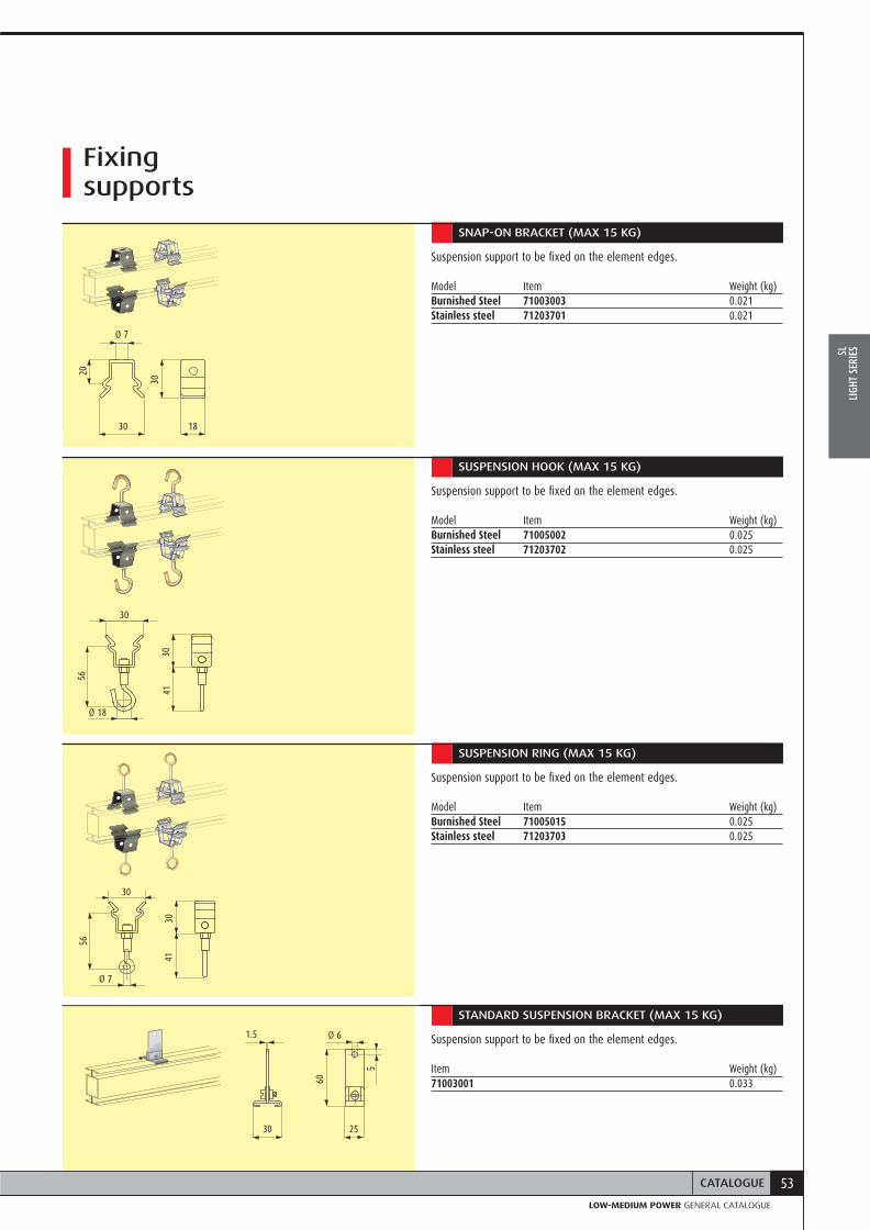
SNAP-ON BRACKET (MAX 15 KG)
Suspension support to be fixed on the element edges.
Model Item Weight (kg)Burnished Steel 71003003 0.021Stainless steel 71203701 0.021
5
60
1.5 Ø 6
Ø 7
3041
18
3041
30
Ø 7
Fixing supports
SUSPENSION HOOK (MAX 15 KG)
Suspension support to be fixed on the element edges.
Model Item Weight (kg)Burnished Steel 71005002 0.025Stainless steel 71203702 0.025
SUSPENSION RING (MAX 15 KG)
Suspension support to be fixed on the element edges.
Model Item Weight (kg)Burnished Steel 71005015 0.025Stainless steel 71203703 0.025
STANDARD SUSPENSION BRACKET (MAX 15 KG)
Suspension support to be fixed on the element edges.
Item Weight (kg)71003001 0.033
30
20
30
Ø 18
5656
2530
30

54 SL - SERIE LUCE
WALL SUSPENSION BRACKET
Item Weight (kg)71003009 0.090
Fixing supports
STAFFA DI SOSPENSIONE A PARETE
5577
96
96 55
46
13 x
6.5
25
FLOOR FIXING BRACKET
Suitable for horizontal floor fastening.
Item Weight (kg)71003018 0.090
STAFFA DI FISSAGGIO A PAVIMENTO
40
69
slot Ø 5 x 12
55CATALOGUE
CATALOGO CONDOTTI SBARRELOW-MEDIUM POWER GENERAL CATALOGUE
SLLI
GHT
SERI
ES
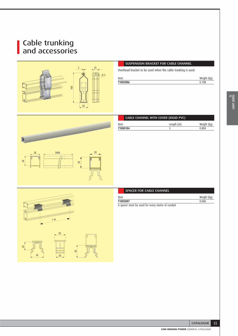
SUSPENSION BRACKET FOR CABLE CHANNEL
Overhead bracket to be used when the cable trunking is used. Item Weight (kg)71003006 0.108
Cable trunking and accessories
50
2 25
Ø 5
160
36 20
30
20
28 3000
28
28
1 m
CABLE CHANNEL WITH COVER (RIGID PVC)
Item Length [m] Weight (kg)71000104 3 0.884
SPACER FOR CABLE CHANNEL
Item Weight (kg)71003007 0.006A spacer must be used for every metre of conduit
2830

Legrand België nvKouterveldstraat, 9
1831 Diegem
Tel.: +32 (0)2 - 719 17 11
Fax: +32 (0)2 - 719 17 00
E-mail: [email protected]
PZ
UC
LM
P10
03
EN