LOW HIGH - accuphase.com · 547W 131W 232W 370W 60W 8 4 2 1 Max. output power 50 100 150 200 250...
4
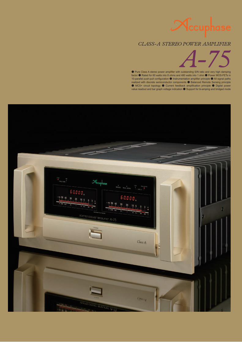
● Pure Class A stereo power amplifier with outstanding S/N ratio and very high damping factor ● Rated for 60 watts into 8 ohms and 480 watts into 1 ohm ● Power MOS-FETs in 10-parallel push-pull configuration ● Instrumentation amplifier principle ● All signal paths realized with discrete semiconductor components ● Balanced Remote Sensing principle ● MCS+ circuit topology ● Current feedback amplification principle ● Digital power value readout and bar graph voltage indication ● Support for bi-amping and bridged mode
Transcript of LOW HIGH - accuphase.com · 547W 131W 232W 370W 60W 8 4 2 1 Max. output power 50 100 150 200 250...
Right speakerLeft speaker
RIGHT RIGHT LEFTLEFT
Right speakerLeft speaker
LOW HIGH
+- +-
LOW HIGH
+- +-
LEFTinput
LEFTinput
LEFTinput
LEFTinput
Dual mono connection indicator
Meter operation selectorOFF / ALL / dB / WDigital power meter range selectorAUTO / 10W / 100W / 1000W
Hold time indicator
Bridged connection indicator
Input type indicators
Power switch Button for opening sub panel
Input selector buttonHold time selector button
Gain selectorMAX / −3dB / −6dB / −12dB Operation selector
DUAL MONO / NORMAL / BRIDGE
AC power supplyconnector★
Line input connectors
Speaker terminals(Same signal at upper and lower connectors)
Balanced input phase selector
Balanced input connectors[Pin ② − Pin ③ + ]* Can be changed with phase selector switch
Digital power meterBar graph meter
Rear PanelFront Panel
Set the operation mode selector of each A-75 unit to BRIDGE.
Set the operation mode selector of each A-75 unit to DUAL MONO.
"BRIDGE" LEDon front panel is lit.
"DUAL MONO" LED on front panel is lit.Preamplifier Preamplifier
A-75 for left channel A-75 for right channel A-75 for left channel A-75 for right channel
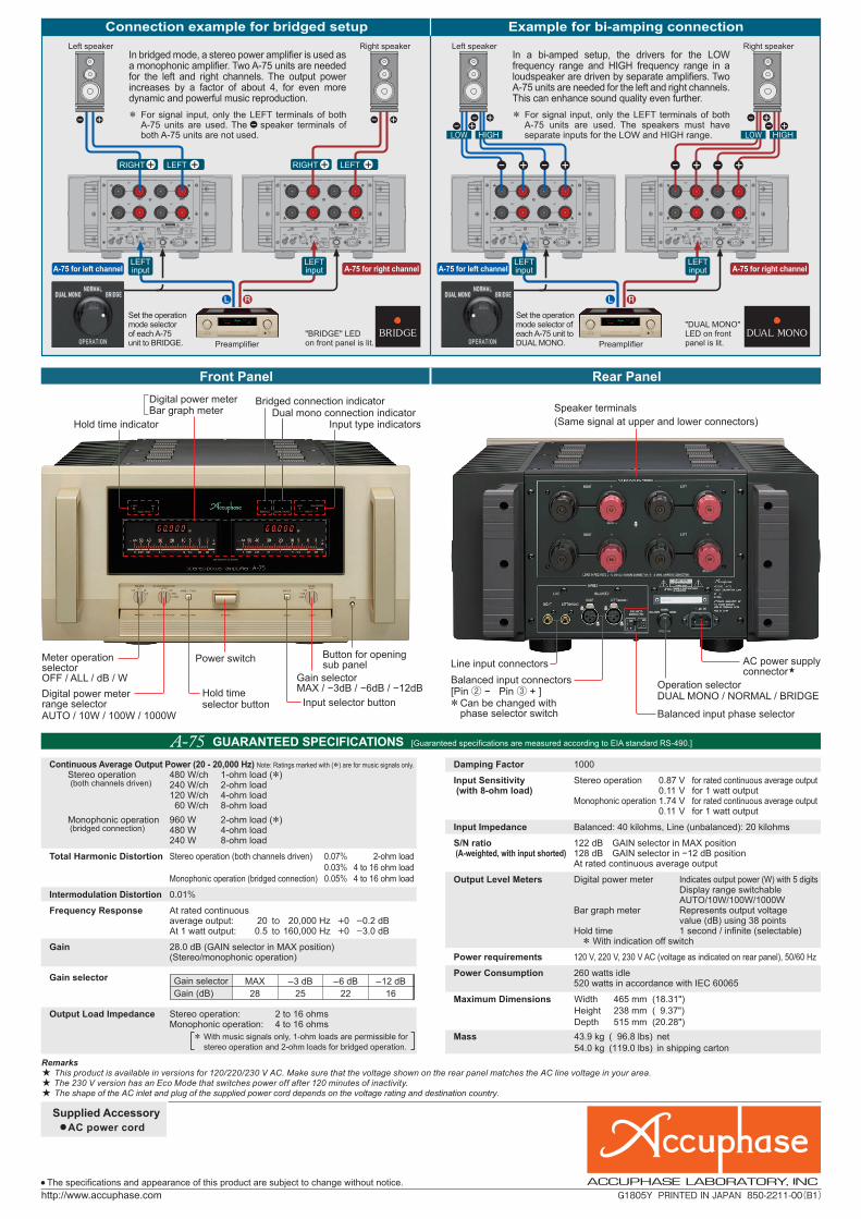
Continuous Average Output Power (20 - 20,000 Hz) Note: Ratings marked with (*) are for music signals only. Stereo operation 480 W/ch 1-ohm load (*) (both channels driven) 240 W/ch 2-ohm load 120 W/ch 4-ohm load 60 W/ch 8-ohm load Monophonic operation 960 W 2-ohm load (*) (bridged connection) 480 W 4-ohm load 240 W 8-ohm load
Total Harmonic Distortion Stereo operation (both channels driven) 0.07% 2-ohm load 0.03% 4 to 16 ohm load Monophonic operation (bridged connection) 0.05% 4 to 16 ohm load
Intermodulation Distortion 0.01%
Frequency Response At rated continuous average output: 20 to 20,000 Hz +0 –0.2 dB At 1 watt output: 0.5 to 160,000 Hz +0 –3.0 dB
Gain 28.0 dB (GAIN selector in MAX position) (Stereo/monophonic operation)
Gain selector
Output Load Impedance Stereo operation: 2 to 16 ohms Monophonic operation: 4 to 16 ohms
Damping Factor 1000
Input Sensitivity Stereo operation 0.87 V for rated continuous average output (with 8-ohm load) 0.11 V for 1 watt output Monophonic operation 1.74 V for rated continuous average output 0.11 V for 1 watt output
Input Impedance Balanced: 40 kilohms, Line (unbalanced): 20 kilohms
S/N ratio 122 dB GAIN selector in MAX position (A-weighted, with input shorted) 128 dB GAIN selector in −12 dB position At rated continuous average output
Output Level Meters Digital power meter Indicates output power (W) with 5 digits Display range switchable AUTO/10W/100W/1000W Bar graph meter Represents output voltage value (dB) using 38 points Hold time 1 second / infinite (selectable) * With indication off switch
Power requirements 120 V, 220 V, 230 V AC (voltage as indicated on rear panel), 50/60 Hz
Power Consumption 260 watts idle 520 watts in accordance with IEC 60065
Maximum Dimensions Width 465 mm ( 18.31") Height 238 mm ( 9.37") Depth 515 mm ( 20.28")Mass 43.9 kg ( 96.8 lbs) net 54.0 kg (119.0 lbs) in shipping carton
* With music signals only, 1-ohm loads are permissible for stereo operation and 2-ohm loads for bridged operation.
● Pure Class A stereo power amplifier with outstanding S/N ratio and very high damping factor ● Rated for 60 watts into 8 ohms and 480 watts into 1 ohm ● Power MOS-FETs in 10-parallel push-pull configuration ● Instrumentation amplifier principle ● All signal paths realized with discrete semiconductor components ● Balanced Remote Sensing principle ● MCS+ circuit topology ● Current feedback amplification principle ● Digital power value readout and bar graph voltage indication ● Support for bi-amping and bridged mode
● AC power cordSupplied Accessory
Connection example for bridged setup Example for bi-amping connection
Gain selectorGain (dB)
MAX28
–3 dB25
–6 dB22
–12 dB16
In a bi-amped setup, the drivers for the LOW frequency range and HIGH frequency range in a loudspeaker are driven by separate amplifiers. Two A-75 units are needed for the left and right channels. This can enhance sound quality even further.* For signal input, only the LEFT terminals of both
A-75 units are used. The speakers must have separate inputs for the LOW and HIGH range.
In bridged mode, a stereo power amplifier is used as a monophonic amplifier. Two A-75 units are needed for the left and right channels. The output power increases by a factor of about 4, for even more dynamic and powerful music reproduction.* For signal input, only the LEFT terminals of both
A-75 units are used. The speaker terminals of both A-75 units are not used.
5年間保証
Remarks This product is available in versions for 120/220/230 V AC. Make sure that the voltage shown on the rear panel matches the AC line voltage in your area.
The 230 V version has an Eco Mode that switches power off after 120 minutes of inactivity. The shape of the AC inlet and plug of the supplied power cord depends on the voltage rating and destination country.
● The specifications and appearance of this product are subject to change without notice.
★★★
GUARANTEED SPECIFICATIONS [Guaranteed specifications are measured according to EIA standard RS-490.]
G1805Y PRINTED IN JAPAN 850-2211-00(B1)
マゼンダはDIC-160 シアンは指定色

547W
131W
232W
370W
547W
60W60W
8 4 2 1
131W
232W
370W
Max. output power
50
100
150
200
250
300
350
400
450
500
550
Impedance (Ohms)
Rated output power
480W480W
240W240W
120W120W
– INPUT
+ INPUT
OUTPUT
+
–FEEDBACKNETWORK
FEEDBACKNETWORK
GAIN CONTROLCIRCUIT
–
+
+
–
10-parallel power amplifier
Signal input sectionGAIN 22 dB
Amplification sectionGAIN 6 dB
Power amplification stage GAIN 6 dBVoltage amplification stageMCS+ (Multiple Circuit Summing)
Power amplification stagePower MOS-FETs in 10-parallel push-pull configuration
Signal input stage GAIN 22 dB
GAIN < MAX, –3, –6, –12 dB >
BIAS
BIAS
BIAS
OUTPUT
+ B4
- B4
+ INPUT
- INPUT
+ B3
- B3
- B2
BIAS
+ B2
- B1
+ B1
- B1
+ B1
-
+
Feedback Network
DC Servo
Gain SelectorMAX -3 dB-6 dB
-12 dB
BIAS
BIAS
GND
GND
19.5 μV (S/N ratio: 121 dB)Previous model
17.4 μV (S/N ratio: 122 dB)A-7511% lower
1000A-75
800Previous model25% improvement
Output power characteristics suitable for constant voltage drive
– INPUT
+ INPUT+
–NFB
NETWORK
NFBNETWORK
GAINCONTROL
–
+
+
–POWERAMP.
Signal Sensing
Ground Sensing
Speaker Terminals
Signal+
GND-
Out
put p
ower
(W)
BIAS
Power MOS-FETs
Operation selector
Edgewise coil
MOS-FET switches
Protection circuit assembly
Digital power meter/bar graph meter
Phase selector
Supported spade lug dimensions
Top plate with elegant hairline finish
Signal input section
■ Instrumentation amplifier principle ■ Output noise
■ Damping Factor
■ Output power characteristics
■ Circuit diagram of amplifier section
●❶ ●❷ ●❸ ●❹ ●❺
Filtering capacitors
Power amplification stage with large heat sinks
Massive toroidal transformer
■ Balanced Remote Sensing
●●●
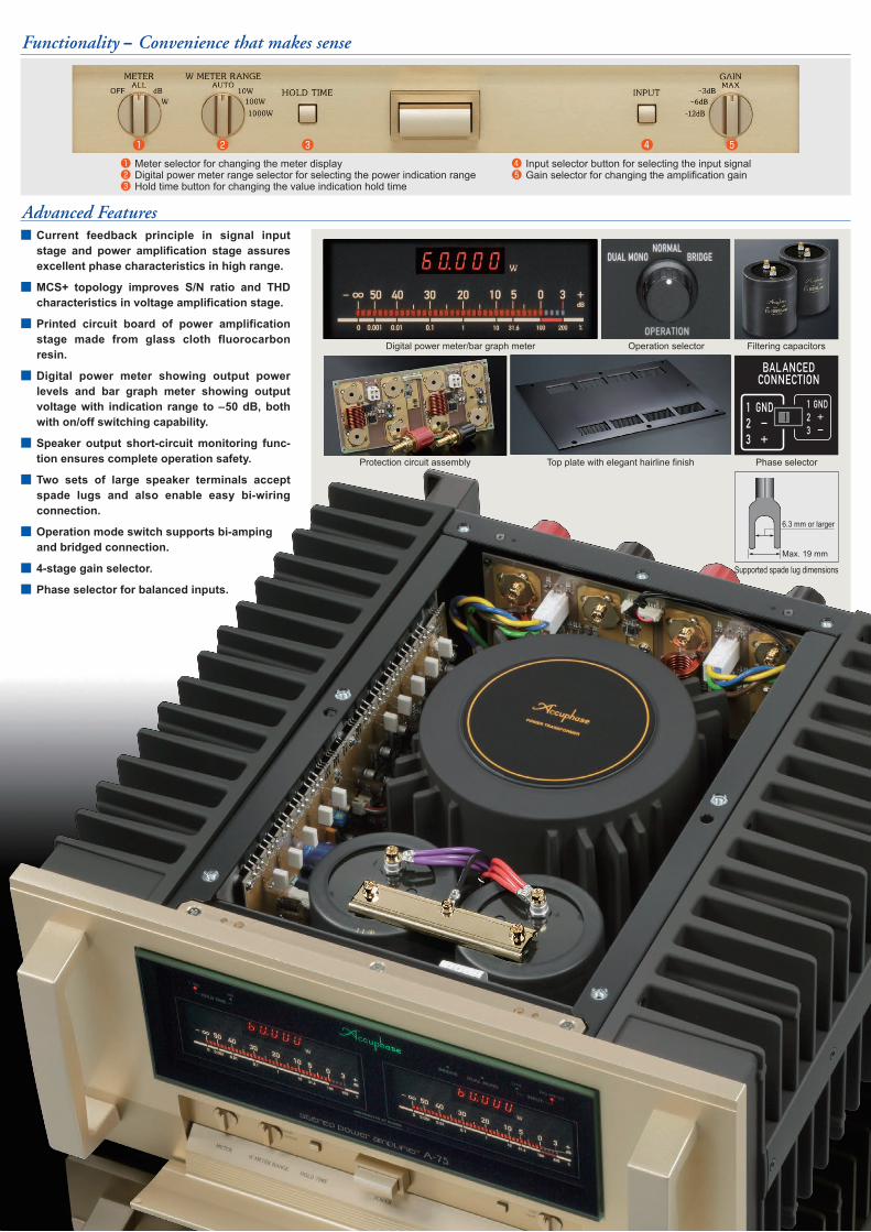
❶ Meter selector for changing the meter display❷ Digital power meter range selector for selecting the power indication range❸ Hold time button for changing the value indication hold time
●●❹ Input selector button for selecting the input signal❺ Gain selector for changing the amplification gain
Instrumentation amplifier topology using discrete semiconductors realizes ideal gain allocation. Balanced Remote Sensing optimizes efficiency of negative feedback. 10-parallel push-pull configuration in power amplification stage. The overall result is outstanding S/N ratio and amazingly high damping factor. Furthermore, constant-voltage drive handles even drastic speaker impedance fluctuations with ease. Power MOS-FETs and other carefully selected components and materials make this Pure Class A Stereo Power Amplifier a sheer delight to experience.
A New Age Begins With a Supreme Pure Class A Stereo Power Amplifier.
Technology development ahead of the curveAdvanced Features
Functionality ‒ Convenience that makes sense
The A-75 uses a balanced instrumentation amplifier circuit configu-ration throughout all amplification stages, minimizing susceptibility to noise and ensuring outstanding characteristics. The signal input stage is configured with discrete semiconductors as a push-pull circuit. This makes it possible to allocate a high gain of 22 dB (factor of approx. 12.6) to this section and conversely keep the gain of the power amplification section to a low 6 dB (approx. x2.0). As a result, even large signal amplitudes are conveyed accurately from the signal input stage to the power amplification stage, and noise components processed in the amplification stage are kept low. Compared to the previous model, this results in a noise reduction of 11%. S/N ratio is rated at an astonishing 122 dB (at max gain setting), which manifests itself in superb sonic clarity.
To correctly track the dynamic changes in loudspeaker impedance and drive the speakers with ideal characteristics, the power amplifier output impedance needs to be kept as low as possible, which in turn means an increase in the damping factor. To achieve this aim, the A-75 not only positions the negative feedback sensing point close to the speaker terminals, it also obtains sensing information from the ground line at the same time. This method is called Balanced Remote Sensing. The aim is to minimize output impedance and therefore achieve a significant increase of the damping factor. Furthermore, ten power MOS-FETs with excellent current capacity are used in a parallel configuration, and MOS-FET switches that eliminate all mechanical contacts guarantee outstanding long-term reliability. The edgewise coil with large cross-section area, Hall element for current detection, and many other sophisticated features further contribute to reduced output impedance. The end result is a damping factor rating of 1,000 which represents a 25% improvement over the previous model.
■ Current feedback principle in signal input stage and power amplification stage assures excellent phase characteristics in high range.
■ MCS+ topology improves S/N ratio and THD characteristics in voltage amplification stage.
■ Printed circuit board of power amplification stage made from glass cloth fluorocarbon resin.
■ Digital power meter showing output power levels and bar graph meter showing output voltage with indication range to –50 dB, both with on/off switching capability.
■ Speaker output short-circuit monitoring func-tion ensures complete operation safety.
■ Two sets of large speaker terminals accept spade lugs and also enable easy bi-wiring connection.
■ Operation mode switch supports bi-amping and bridged connection.
■ 4-stage gain selector.
■ Phase selector for balanced inputs.
High S/N ratio results in sparkling clarity
High damping factor realizes ideal speaker drive
A massive toroidal power transformer and large filtering capacitors (100,000 μF x 2) in the power supply ensure that plenty of power is available for handling high amplitude input signals, and large heat sinks efficiently dissipate any excess thermal energy. As a result, the power amplification stage is rated for a continuous 60 watts into 8 ohms, 120 watts into 4 ohms, 240 watts into 2 ohms and 480 watts into 1 ohm (music signals). This linear power progression demonstrates that constant voltage drive has been successfully realized. The maximum output rating is 131 watts into 8 ohms, 232 watts into 4 ohms, 370 watts into 2 ohms and 547 watts into 1 ohm (music signals). Although a Pure Class A Stereo Power Amplifier, the A-75 can easily drive even large and demanding speakers.
Max. 19 mm
6.3 mm or larger
547W
131W
232W
370W
547W
60W60W
8 4 2 1
131W
232W
370W
Max. output power
50
100
150
200
250
300
350
400
450
500
550
Impedance (Ohms)
Rated output power
480W480W
240W240W
120W120W
– INPUT
+ INPUT
OUTPUT
+
–FEEDBACKNETWORK
FEEDBACKNETWORK
GAIN CONTROLCIRCUIT
–
+
+
–
10-parallel power amplifier
Signal input sectionGAIN 22 dB
Amplification sectionGAIN 6 dB
Power amplification stage GAIN 6 dBVoltage amplification stageMCS+ (Multiple Circuit Summing)
Power amplification stagePower MOS-FETs in 10-parallel push-pull configuration
Signal input stage GAIN 22 dB
GAIN < MAX, –3, –6, –12 dB >
BIAS
BIAS
BIAS
OUTPUT
+ B4
- B4
+ INPUT
- INPUT
+ B3
- B3
- B2
BIAS
+ B2
- B1
+ B1
- B1
+ B1
-
+
Feedback Network
DC Servo
Gain SelectorMAX -3 dB-6 dB
-12 dB
BIAS
BIAS
GND
GND
19.5 μV (S/N ratio: 121 dB)Previous model
17.4 μV (S/N ratio: 122 dB)A-7511% lower
1000A-75
800Previous model25% improvement
Output power characteristics suitable for constant voltage drive
– INPUT
+ INPUT+
–NFB
NETWORK
NFBNETWORK
GAINCONTROL
–
+
+
–POWERAMP.
Signal Sensing
Ground Sensing
Speaker Terminals
Signal+
GND-
Out
put p
ower
(W)
BIAS
Power MOS-FETs
Operation selector
Edgewise coil
MOS-FET switches
Protection circuit assembly
Digital power meter/bar graph meter
Phase selector
Supported spade lug dimensions
Top plate with elegant hairline finish
Signal input section
■ Instrumentation amplifier principle ■ Output noise
■ Damping Factor
■ Output power characteristics
■ Circuit diagram of amplifier section
●❶ ●❷ ●❸ ●❹ ●❺
Filtering capacitors
Power amplification stage with large heat sinks
Massive toroidal transformer
■ Balanced Remote Sensing
●●●
❶ Meter selector for changing the meter display❷ Digital power meter range selector for selecting the power indication range❸ Hold time button for changing the value indication hold time
●●❹ Input selector button for selecting the input signal❺ Gain selector for changing the amplification gain
Instrumentation amplifier topology using discrete semiconductors realizes ideal gain allocation. Balanced Remote Sensing optimizes efficiency of negative feedback. 10-parallel push-pull configuration in power amplification stage. The overall result is outstanding S/N ratio and amazingly high damping factor. Furthermore, constant-voltage drive handles even drastic speaker impedance fluctuations with ease. Power MOS-FETs and other carefully selected components and materials make this Pure Class A Stereo Power Amplifier a sheer delight to experience.
A New Age Begins With a Supreme Pure Class A Stereo Power Amplifier.
Technology development ahead of the curveAdvanced Features
Functionality ‒ Convenience that makes sense
The A-75 uses a balanced instrumentation amplifier circuit configu-ration throughout all amplification stages, minimizing susceptibility to noise and ensuring outstanding characteristics. The signal input stage is configured with discrete semiconductors as a push-pull circuit. This makes it possible to allocate a high gain of 22 dB (factor of approx. 12.6) to this section and conversely keep the gain of the power amplification section to a low 6 dB (approx. x2.0). As a result, even large signal amplitudes are conveyed accurately from the signal input stage to the power amplification stage, and noise components processed in the amplification stage are kept low. Compared to the previous model, this results in a noise reduction of 11%. S/N ratio is rated at an astonishing 122 dB (at max gain setting), which manifests itself in superb sonic clarity.
To correctly track the dynamic changes in loudspeaker impedance and drive the speakers with ideal characteristics, the power amplifier output impedance needs to be kept as low as possible, which in turn means an increase in the damping factor. To achieve this aim, the A-75 not only positions the negative feedback sensing point close to the speaker terminals, it also obtains sensing information from the ground line at the same time. This method is called Balanced Remote Sensing. The aim is to minimize output impedance and therefore achieve a significant increase of the damping factor. Furthermore, ten power MOS-FETs with excellent current capacity are used in a parallel configuration, and MOS-FET switches that eliminate all mechanical contacts guarantee outstanding long-term reliability. The edgewise coil with large cross-section area, Hall element for current detection, and many other sophisticated features further contribute to reduced output impedance. The end result is a damping factor rating of 1,000 which represents a 25% improvement over the previous model.
■ Current feedback principle in signal input stage and power amplification stage assures excellent phase characteristics in high range.
■ MCS+ topology improves S/N ratio and THD characteristics in voltage amplification stage.
■ Printed circuit board of power amplification stage made from glass cloth fluorocarbon resin.
■ Digital power meter showing output power levels and bar graph meter showing output voltage with indication range to –50 dB, both with on/off switching capability.
■ Speaker output short-circuit monitoring func-tion ensures complete operation safety.
■ Two sets of large speaker terminals accept spade lugs and also enable easy bi-wiring connection.
■ Operation mode switch supports bi-amping and bridged connection.
■ 4-stage gain selector.
■ Phase selector for balanced inputs.
High S/N ratio results in sparkling clarity
High damping factor realizes ideal speaker drive
A massive toroidal power transformer and large filtering capacitors (100,000 μF x 2) in the power supply ensure that plenty of power is available for handling high amplitude input signals, and large heat sinks efficiently dissipate any excess thermal energy. As a result, the power amplification stage is rated for a continuous 60 watts into 8 ohms, 120 watts into 4 ohms, 240 watts into 2 ohms and 480 watts into 1 ohm (music signals). This linear power progression demonstrates that constant voltage drive has been successfully realized. The maximum output rating is 131 watts into 8 ohms, 232 watts into 4 ohms, 370 watts into 2 ohms and 547 watts into 1 ohm (music signals). Although a Pure Class A Stereo Power Amplifier, the A-75 can easily drive even large and demanding speakers.
Max. 19 mm
6.3 mm or larger
Right speakerLeft speaker
RIGHT RIGHT LEFTLEFT
Right speakerLeft speaker
LOW HIGH
+- +-
LOW HIGH
+- +-
LEFTinput
LEFTinput
LEFTinput
LEFTinput
Dual mono connection indicator
Meter operation selectorOFF / ALL / dB / WDigital power meter range selectorAUTO / 10W / 100W / 1000W
Hold time indicator
Bridged connection indicator
Input type indicators
Power switch Button for opening sub panel
Input selector buttonHold time selector button
Gain selectorMAX / −3dB / −6dB / −12dB Operation selector
DUAL MONO / NORMAL / BRIDGE
AC power supplyconnector★
Line input connectors
Speaker terminals(Same signal at upper and lower connectors)
Balanced input phase selector
Balanced input connectors[Pin ② − Pin ③ + ]* Can be changed with phase selector switch
Digital power meterBar graph meter
Rear PanelFront Panel
Set the operation mode selector of each A-75 unit to BRIDGE.
Set the operation mode selector of each A-75 unit to DUAL MONO.
"BRIDGE" LEDon front panel is lit.
"DUAL MONO" LED on front panel is lit.Preamplifier Preamplifier
A-75 for left channel A-75 for right channel A-75 for left channel A-75 for right channel
Continuous Average Output Power (20 - 20,000 Hz) Note: Ratings marked with (*) are for music signals only. Stereo operation 480 W/ch 1-ohm load (*) (both channels driven) 240 W/ch 2-ohm load 120 W/ch 4-ohm load 60 W/ch 8-ohm load Monophonic operation 960 W 2-ohm load (*) (bridged connection) 480 W 4-ohm load 240 W 8-ohm load
Total Harmonic Distortion Stereo operation (both channels driven) 0.07% 2-ohm load 0.03% 4 to 16 ohm load Monophonic operation (bridged connection) 0.05% 4 to 16 ohm load
Intermodulation Distortion 0.01%
Frequency Response At rated continuous average output: 20 to 20,000 Hz +0 –0.2 dB At 1 watt output: 0.5 to 160,000 Hz +0 –3.0 dB
Gain 28.0 dB (GAIN selector in MAX position) (Stereo/monophonic operation)
Gain selector
Output Load Impedance Stereo operation: 2 to 16 ohms Monophonic operation: 4 to 16 ohms
Damping Factor 1000
Input Sensitivity Stereo operation 0.87 V for rated continuous average output (with 8-ohm load) 0.11 V for 1 watt output Monophonic operation 1.74 V for rated continuous average output 0.11 V for 1 watt output
Input Impedance Balanced: 40 kilohms, Line (unbalanced): 20 kilohms
S/N ratio 122 dB GAIN selector in MAX position (A-weighted, with input shorted) 128 dB GAIN selector in −12 dB position At rated continuous average output
Output Level Meters Digital power meter Indicates output power (W) with 5 digits Display range switchable AUTO/10W/100W/1000W Bar graph meter Represents output voltage value (dB) using 38 points Hold time 1 second / infinite (selectable) * With indication off switch
Power requirements 120 V, 220 V, 230 V AC (voltage as indicated on rear panel), 50/60 Hz
Power Consumption 260 watts idle 520 watts in accordance with IEC 60065
Maximum Dimensions Width 465 mm ( 18.31") Height 238 mm ( 9.37") Depth 515 mm ( 20.28")Mass 43.9 kg ( 96.8 lbs) net 54.0 kg (119.0 lbs) in shipping carton
* With music signals only, 1-ohm loads are permissible for stereo operation and 2-ohm loads for bridged operation.
● Pure Class A stereo power amplifier with outstanding S/N ratio and very high damping factor ● Rated for 60 watts into 8 ohms and 480 watts into 1 ohm ● Power MOS-FETs in 10-parallel push-pull configuration ● Instrumentation amplifier principle ● All signal paths realized with discrete semiconductor components ● Balanced Remote Sensing principle ● MCS+ circuit topology ● Current feedback amplification principle ● Digital power value readout and bar graph voltage indication ● Support for bi-amping and bridged mode
● AC power cordSupplied Accessory
Connection example for bridged setup Example for bi-amping connection
Gain selectorGain (dB)
MAX28
–3 dB25
–6 dB22
–12 dB16
In a bi-amped setup, the drivers for the LOW frequency range and HIGH frequency range in a loudspeaker are driven by separate amplifiers. Two A-75 units are needed for the left and right channels. This can enhance sound quality even further.* For signal input, only the LEFT terminals of both
A-75 units are used. The speakers must have separate inputs for the LOW and HIGH range.
In bridged mode, a stereo power amplifier is used as a monophonic amplifier. Two A-75 units are needed for the left and right channels. The output power increases by a factor of about 4, for even more dynamic and powerful music reproduction.* For signal input, only the LEFT terminals of both
A-75 units are used. The speaker terminals of both A-75 units are not used.
5年間保証
Remarks This product is available in versions for 120/220/230 V AC. Make sure that the voltage shown on the rear panel matches the AC line voltage in your area.
The 230 V version has an Eco Mode that switches power off after 120 minutes of inactivity. The shape of the AC inlet and plug of the supplied power cord depends on the voltage rating and destination country.
● The specifications and appearance of this product are subject to change without notice.
★★★
GUARANTEED SPECIFICATIONS [Guaranteed specifications are measured according to EIA standard RS-490.]
G1805Y PRINTED IN JAPAN 850-2211-00(B1)
マゼンダはDIC-160 シアンは指定色