LOW-FREQUENCY COMPENSATION OF PIEZOELECTRIC MICRO … · ISSN 1330-3651(Print), ISSN 1848-6339...
8
Jiangpan Chen, Wei Cheng Kompenzacija niske frekvencije probne platforme s piezoelektričnim mikro vibracijama Tehnički vjesnik 23, 5(2016), 1251-1258 1251 ISSN 1330-3651(Print), ISSN 1848-6339 (Online) DOI: 10.17559/TV-20150324061210 LOW-FREQUENCY COMPENSATION OF PIEZOELECTRIC MICRO-VIBRATIONS TEST PLATFORM Jiangpan Chen, Wei Cheng Original scientific paper PMTP (piezoelectric micro-vibrations test platform) is widely used to test the micro-vibrations emitted by the rotary equipment on a spacecraft. Due to the poor performance of the piezoelectric sensor in low frequency band, the test reliability of PMTP is low. A low-frequency compensation method is proposed to solve this problem. Firstly, the low-frequency compensation method of a single-axis piezoelectric force sensor is introduced and verified by experimental test. Secondly, the low-frequency compensation method of PMTP, which consists of eight single-axis piezoelectric force sensors, is proposed. Lastly, the low-frequency compensation method of PMTP is verified by experimental test. The results show that this method can effectively compensate the performance of PMTP in low frequency band. Keywords: low-frequency compensation; micro-vibrations; piezoelectric force sensor; piezoelectric micro-vibrations test platform Kompenzacija niske frekvencije probne platforme s piezoelektričnim mikro vibracijama Izvorni znanstveni članak PMTP (probna platforma s piezoelektričnim mikro-vibracijama) općenito se rabi za ispitivanje mikro-vibracija koje ispušta rotirajuća oprema na svemirskoj letjelici. Zbog lošeg funkcioniranja piezoelektričnog senzora u zoni niskih frekvencija, pouzdanost ispitivanja PMTP je mala. Za rješenje tog problema predlaže se metoda kompenzacije niske frekvencije. Najprije se uvodi nisko frekvencijska metoda kompenzacije jednoosovinskog piezoelektričnog sensora snage i verificira eksperimentalnim ispitivanjem. Zatim se predlaže metoda kompenzacije niske frekvencije PMTP-a koja se sastoji od osam jednoosovinskih piezoelektričnih senzora snage. Na kraju se metoda kompenzacije niske frekvencije PMTP-a verificira eksperimentalnim ispitivanjem. Rezultati pokazuju da se tom metodom može učinkovito kompenzirati funkcioniranje PMTP-a u zoni niskih frekvencija. Ključne riječi: kompenzacije niske frekvencije; mikro-vibracije; probna platforma s piezoelektričnim mikro vibracijama; piezoelektrični senzor snage 1 Introduction The vibrations generated by the rotary equipment on spacecraft can degrade the key performance of spacecraft, such as imaging quality and pointing accuracy. In general, such vibrations are of low amplitude, less than 1 kHz, and are named as ‘micro-vibrations’ [1]. There is a lot of rotary equipment on spacecraft, for instance, M/RWA (Momentum/Reaction Wheel Assembly), CMG (Control Moment Gyro), SADA (Solar Array Drive Assembly) and CSA (Camera Shutter Assembly) [2÷5]. Therefore, to test the micro-vibrations caused by the rotary equipment precisely on the earth is the key to designing the damping and isolation of spacecraft. At present, the most popular test platform, used to test the micro-vibrations aroused by the rotary equipment on spacecraft, is PMTP [5÷11], which is composed of several piezoelectric force sensors. Piezoelectric force sensors, characterized by high sensitivity, high resolution and wide test range, are extensively used in the test field of a dynamic force [12]. However, due to the leakage of electric charge, the performance of the piezoelectric force sensor in low frequency band is poor [13], which leads to an unreliable test result of PMTP in low frequency band. Due to the longer exposure time than low orbit remote sensing satellite, the performance of high orbit remote sensing satellite is more sensitive to the micro-vibrations in low frequency band, and to test the micro-vibrations produced by the rotary equipment in low frequency band is impending. Thus, it is necessary to compensate the performance of PMTP in low frequency band. In general, two ways are frequently used to compensate the performance of the piezoelectric force sensor in low frequency band, which are as follows: 1) Changing the structure and designing parameters of the piezoelectric force sensor to improve its performance in low frequency band. However, it is always limited by many objective conditions and difficult to obtain an ideal result. 2) Post-processing the test signals of the piezoelectric force sensor to achieve a desired result. This way has the advantages of good flexibility and easy implementation [14]. In this paper, the second way is the basis for compensating the performance of the piezoelectric force sensor and PMTP. The remainder of this thesis proceeds as follows: section 2 introduces and verifies the low-frequency compensation method of a single-axis piezoelectric force sensor; section 3 describes the calibration method and compensation method of PMTP; section 4 verifies the performance of the compensation method proposed in this paper; finally, section 5 summarizes the paper and states the conclusions drawn from this work. 2 Single-axis piezoelectric force sensor In this section, the low-frequency compensation method of a single-axis piezoelectric force sensor and the corresponding experimental verification are presented. 2.1 Compensation method The relationship between the external force acting on the piezoelectric force sensor and the output voltage can be defined as [12]:
Transcript of LOW-FREQUENCY COMPENSATION OF PIEZOELECTRIC MICRO … · ISSN 1330-3651(Print), ISSN 1848-6339...
Jiangpan Chen, Wei Cheng Kompenzacija niske frekvencije probne platforme s piezoelektričnim mikro vibracijama
Tehnički vjesnik 23, 5(2016), 1251-1258 1251
ISSN 1330-3651(Print), ISSN 1848-6339 (Online) DOI: 10.17559/TV-20150324061210
LOW-FREQUENCY COMPENSATION OF PIEZOELECTRIC MICRO-VIBRATIONS TEST PLATFORM Jiangpan Chen, Wei Cheng
Original scientific paper PMTP (piezoelectric micro-vibrations test platform) is widely used to test the micro-vibrations emitted by the rotary equipment on a spacecraft. Due to the poor performance of the piezoelectric sensor in low frequency band, the test reliability of PMTP is low. A low-frequency compensation method is proposed to solve this problem. Firstly, the low-frequency compensation method of a single-axis piezoelectric force sensor is introduced and verified by experimental test. Secondly, the low-frequency compensation method of PMTP, which consists of eight single-axis piezoelectric force sensors, is proposed. Lastly, the low-frequency compensation method of PMTP is verified by experimental test. The results show that this method can effectively compensate the performance of PMTP in low frequency band. Keywords: low-frequency compensation; micro-vibrations; piezoelectric force sensor; piezoelectric micro-vibrations test platform
Kompenzacija niske frekvencije probne platforme s piezoelektričnim mikro vibracijama
Izvorni znanstveni članak PMTP (probna platforma s piezoelektričnim mikro-vibracijama) općenito se rabi za ispitivanje mikro-vibracija koje ispušta rotirajuća oprema na svemirskoj letjelici. Zbog lošeg funkcioniranja piezoelektričnog senzora u zoni niskih frekvencija, pouzdanost ispitivanja PMTP je mala. Za rješenje tog problema predlaže se metoda kompenzacije niske frekvencije. Najprije se uvodi nisko frekvencijska metoda kompenzacije jednoosovinskog piezoelektričnog sensora snage i verificira eksperimentalnim ispitivanjem. Zatim se predlaže metoda kompenzacije niske frekvencije PMTP-a koja se sastoji od osam jednoosovinskih piezoelektričnih senzora snage. Na kraju se metoda kompenzacije niske frekvencije PMTP-a verificira eksperimentalnim ispitivanjem. Rezultati pokazuju da se tom metodom može učinkovito kompenzirati funkcioniranje PMTP-a u zoni niskih frekvencija. Ključne riječi: kompenzacije niske frekvencije; mikro-vibracije; probna platforma s piezoelektričnim mikro vibracijama; piezoelektrični senzor snage
1 Introduction
The vibrations generated by the rotary equipment on spacecraft can degrade the key performance of spacecraft, such as imaging quality and pointing accuracy. In general, such vibrations are of low amplitude, less than 1 kHz, and are named as ‘micro-vibrations’ [1]. There is a lot of rotary equipment on spacecraft, for instance, M/RWA (Momentum/Reaction Wheel Assembly), CMG (Control Moment Gyro), SADA (Solar Array Drive Assembly) and CSA (Camera Shutter Assembly) [2÷5]. Therefore, to test the micro-vibrations caused by the rotary equipment precisely on the earth is the key to designing the damping and isolation of spacecraft.
At present, the most popular test platform, used to test the micro-vibrations aroused by the rotary equipment on spacecraft, is PMTP [5÷11], which is composed of several piezoelectric force sensors. Piezoelectric force sensors, characterized by high sensitivity, high resolution and wide test range, are extensively used in the test field of a dynamic force [12]. However, due to the leakage of electric charge, the performance of the piezoelectric force sensor in low frequency band is poor [13], which leads to an unreliable test result of PMTP in low frequency band. Due to the longer exposure time than low orbit remote sensing satellite, the performance of high orbit remote sensing satellite is more sensitive to the micro-vibrations in low frequency band, and to test the micro-vibrations produced by the rotary equipment in low frequency band is impending. Thus, it is necessary to compensate the performance of PMTP in low frequency band.
In general, two ways are frequently used to compensate the performance of the piezoelectric force sensor in low frequency band, which are as follows:
1) Changing the structure and designing parameters of the piezoelectric force sensor to improve its performance in low frequency band. However, it is always limited by many objective conditions and difficult to obtain an ideal result.
2) Post-processing the test signals of the piezoelectric force sensor to achieve a desired result. This way has the advantages of good flexibility and easy implementation [14]. In this paper, the second way is the basis for
compensating the performance of the piezoelectric force sensor and PMTP.
The remainder of this thesis proceeds as follows: section 2 introduces and verifies the low-frequency compensation method of a single-axis piezoelectric force sensor; section 3 describes the calibration method and compensation method of PMTP; section 4 verifies the performance of the compensation method proposed in this paper; finally, section 5 summarizes the paper and states the conclusions drawn from this work. 2 Single-axis piezoelectric force sensor
In this section, the low-frequency compensation method of a single-axis piezoelectric force sensor and the corresponding experimental verification are presented. 2.1 Compensation method
The relationship between the external force acting on the piezoelectric force sensor and the output voltage can be defined as [12]:

Low-frequency compensation of piezoelectric micro-vibrations test platform Jiangpan Chen, Wei Cheng
1252 Technical Gazette 23, 5(2016), 1251-1258
,
d
)( d)(
d
)( d
t
tFeRAtU
t
tURC (1)
where U(t) is the output voltage, F(t) is the external force, e is the piezoelectric constant, A is the work area of the piezoelectric element, R and C is the equivalent resistance and equivalent capacitance, respectively.
Thus, the frequency response relationship between the output voltage U(ω) and the external force F(ω) can be written as:
,)(1
)(
Fi
iKU
(2)
where i is the imaginary unit, ω is the angular frequency, K = eA/C and τ = RC is the voltage sensitivity and discharge time constant of the piezoelectric force sensor, respectively. Both K and τ are constants.
In engineering applications, the test result of the external force F(ω) is drawn from:
,)(
)(K
UFt
(3)
where Ft(ω) is the test result.
Substituting Eq. (2) into Eq. (3), the relationship between the external force F(ω) and the test result Ft(ω) can be obtained as:
).(1
)()(1
)(
ttt F
iFF
i
iF
(4)
Obviously, the test result Ft(ω) would not equal to the
external force F(ω) when the angular frequency ω is in low frequency band. Thus, the performance of the piezoelectric force sensor in low frequency band is poor.
Eq. (4) can be also written as:
,1
)(
)()(
i
i
F
FC
t
(5)
where C(ω) is the compensation function of the single-axis piezoelectric force sensor, and it is the function of the discharge time constant τ.
The low-frequency compensation should be carried out on the output voltage U(ω) as it is the direct test signal. Therefore, the output voltage of the piezoelectric force sensor after compensation can be defined as:
),()()( UCUc (6)
where Uc(ω) is the output voltage after compensation.
As a result, the test result after compensation can be obtained as:
,)()()(
)(K
UC
K
UF c
tc
(7)
where Ftc(ω) is the test result after compensation.
Substituting Eqs. (2) and (5) into Eq. (7), the test result after compensation can be rewritten as:
1
1 .tc
i iK
i iF F FK
(8)
Therefore, the test result after compensation equals
the external force acting on the piezoelectric force sensor. As a consequence, the low-frequency compensation
method of a single-axis piezoelectric force sensor can be summarized as follows:
1) Obtaining the discharge time constant τ of the piezoelectric force sensor to establish the compensation function C(ω).
2) Compensating the output voltage U(ω) by using Eq. (6) to obtain the output voltage after compensation Uc(ω).
3) To achieve the test result after compensation Ftc(ω), which equals the external force F(ω) acting on this force sensor, by using Eq. (7). 2.2 Experimental verification
Two experiments used to verify the low-frequency compensation method of a single-axis piezoelectric force sensor will be described in this section. The first experiment is the identification of the voltage sensitivity K and discharge time constant τ of the piezoelectric force sensor. The second experiment is the verification of the low-frequency compensation method. 2.2.1 Parameters identification
As discussed above, the first step of the low frequency compensation is to identify the discharge time constant τ. Ref. [15] indicates that the output voltage of the piezoelectric force sensor under the action of a step force is given by:
, exp )(
t
aKtU (9)
where a is the amplitude of the step force, K and τ is the voltage sensitivity and discharge time constant, respectively. As a consequence, the unknown parameters K and τ can be identified by fitting the output voltage curve of the piezoelectric force sensor under the action of a known step force.
The picture of the experimental equipment used in the parameters identification experiment is shown in Fig. 1.
Fig. 1 indicates that the single-axis piezoelectric force sensor discussed in this paper is composed of four pieces of P5H piezoelectric ceramic piece in parallel and a specific fixture. The four piezoelectric ceramic pieces are pressed tightly and fixed to a rigid foundation by the specific fixture. The specific fixture is composed of a fixed part and a motion part. An electromagnet is fixed to the centre of the motion part. A weight (1 kg) should be absorbed on the electromagnet when the electromagnet is powered. After the leakage of all the electric charge of the piezoelectric force sensor, cutting off the power of the
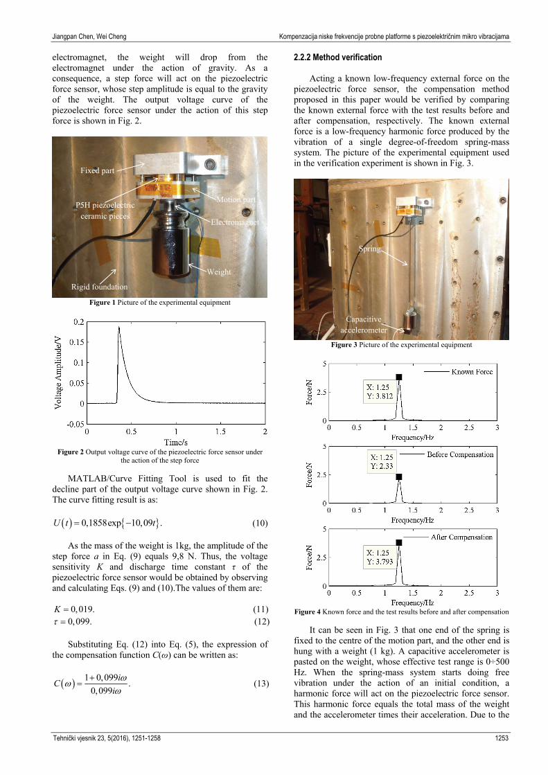
Jiangpan Chen, Wei Cheng Kompenzacija niske frekvencije probne platforme s piezoelektričnim mikro vibracijama
Tehnički vjesnik 23, 5(2016), 1251-1258 1253
electromagnet, the weight will drop from the electromagnet under the action of gravity. As a consequence, a step force will act on the piezoelectric force sensor, whose step amplitude is equal to the gravity of the weight. The output voltage curve of the piezoelectric force sensor under the action of this step force is shown in Fig. 2.
Figure 1 Picture of the experimental equipment
Figure 2 Output voltage curve of the piezoelectric force sensor under
the action of the step force
MATLAB/Curve Fitting Tool is used to fit the decline part of the output voltage curve shown in Fig. 2. The curve fitting result is as:
0,1858exp 10,09 .U t t (10)
As the mass of the weight is 1kg, the amplitude of the step force a in Eq. (9) equals 9,8 N. Thus, the voltage sensitivity K and discharge time constant τ of the piezoelectric force sensor would be obtained by observing and calculating Eqs. (9) and (10).The values of them are:
0,019.K (11) 0,099. (12)
Substituting Eq. (12) into Eq. (5), the expression of
the compensation function C(ω) can be written as:
1 0,099.
0,099
iC
i
(13)
2.2.2 Method verification
Acting a known low-frequency external force on the piezoelectric force sensor, the compensation method proposed in this paper would be verified by comparing the known external force with the test results before and after compensation, respectively. The known external force is a low-frequency harmonic force produced by the vibration of a single degree-of-freedom spring-mass system. The picture of the experimental equipment used in the verification experiment is shown in Fig. 3.
Figure 3 Picture of the experimental equipment
Figure 4 Known force and the test results before and after compensation
It can be seen in Fig. 3 that one end of the spring is fixed to the centre of the motion part, and the other end is hung with a weight (1 kg). A capacitive accelerometer is pasted on the weight, whose effective test range is 0÷500 Hz. When the spring-mass system starts doing free vibration under the action of an initial condition, a harmonic force will act on the piezoelectric force sensor. This harmonic force equals the total mass of the weight and the accelerometer times their acceleration. Due to the
Weight
Electromagnet
Motion part
Fixed part
Rigid foundation
P5H piezoelectric ceramic pieces
Spring
Capacitive accelerometer

Low-frequency compensation of piezoelectric micro-vibrations test platform Jiangpan Chen, Wei Cheng
1254 Technical Gazette 23, 5(2016), 1251-1258
total mass of the weight and the accelerometer is known already and their acceleration can be tested by the accelerometer, this harmonic force is a known force. The known harmonic force and the test results before and after compensation are shown in Fig. 4.
The conclusions obtained from Fig. 4 are as follows: 1) The frequency of the known harmonic force is 1,25
Hz, which is in low frequency band. 2) The single-axis piezoelectric force sensor discussed
in this paper is able to test the vibration frequency precisely either before compensation or after compensation.
3) The vibration amplitude test error of the piezoelectric force sensor before and after compensation is −38,88 % and −0,50 %, respectively. Thus, the low-frequency compensation method proposed in this paper can effectively compensate the performance of the single-axis piezoelectric force sensor in low frequency band.
3 Piezoelectric micro-vibrations test platform
The picture and inner sketch of PMTP discussed in this paper are shown in Fig. 5 and Fig. 6, respectively.
Figure 5 Picture of PMTP
Figure 6 Inner sketch of PMTP
Fig. 6 presents that the PMTP discussed in this paper
is mainly composed of eight single-axis piezoelectric force sensors (S1÷S8) and a load plate. Four sensors (S1÷S4) are arranged along the horizontal direction to test the three components of Fx, Fy and Mz,the other four (S5÷S8) are arranged along the vertical direction to test the other three components of Fz, Mx and My.
3.1 Calibration method
The micro-vibrations emitted by the rotary equipment hard mounted to PMTP will act on the equivalent centre of the installation interface in the form of six-component disturbance force/moment (Fx, Fy, Fz, Mx, My and Mz). Meanwhile, the eight single-axis force sensors of PMTP will output eight voltage signals. The purpose of the calibration process is to achieve the transforming relationship between the eight output voltage signals and the six-component disturbance force/moment. The transforming relationship is a matrix named calibration matrix [16]. The relationship between the eight output voltage signals and the six-component disturbance force/moment can be expressed as:
,188616 UWF (14)
where F is the six-component disturbance force/moment, W is the calibration matrix and U is the output voltage.
Calibration matrix W can be obtained by acting a known six-component force/moment on the equivalent centre of the installation interface and testing the output voltage signals. However, to act a known six-component force/moment on the equivalent centre directly is difficult to achieve. A rigid calibration device with twelve loading points is designed. According to the simplification principles of the space force system, the known six-component force/moment can be obtained by acting known single-axis forces on different loading points [16]. The sketch of the calibration device is shown in Fig. 7.
Figure 7 Sketch of the calibration device
T
6 12
0 1 0 0
0 1 0 0
1 0 0 0
1 0 0 0
0 1 0 0
0 1 0 0.1 0 0 0
1 0 0 0
0 0 1 0
0 0 1 0
0 0 1 0
0 0 1 0
T
z x
z x
z y
z y
z x
z x
z y
z y
y x
y x
y x
y x
L L
L L
L L
L L
L L
L L
L L
L L
L L
L L
L L
L L
(15)
X
Y
Z

Jiangpan Chen, Wei Cheng Kompenzacija niske frekvencije probne platforme s piezoelektričnim mikro vibracijama
Tehnički vjesnik 23, 5(2016), 1251-1258 1255
In Fig. 7, O is the equivalent centre of the installation interface and Lx, Ly and Lz are the arms of force between the loading points and the equivalent centre O. Thus, to simplify the twelve single-axis forces to the equivalent centre needs to multiply by a transformation matrix. The expression of the transformation matrix is given by Eq. (15).
The known single-axis forces acting on the calibration device are step forces loaded by a specific loading device consisting of an adjustable bracket, a weight and a piece of cotton line shown in Fig. 8.
Figure 8 Picture of the known step force loading device
In Fig. 8, the gravity of the weight would act on the
loading point orthogonally through the bracket and the cotton line. When the weight stops swinging, to burn out the cotton line that a step force, whose amplitude is the gravity of the weight, will act on the loading point. The bracket is consisting of two aluminium beams, two pulleys, a biaxial translation stage and a magnet base. Beam1 is used to mount the whole loading device to the rigid foundation through the magnet base. Beam1 and beam2 are connected by the biaxial translation stage. The fixed part of the biaxial translation stage connects with beam1 and the motion part connects with beam2. Then the position of beam2 can be adjusted finely with respect to beam1. Therefore, the maximum orthogonality between the cotton line and the loading point can be guaranteed. The purpose of the pulleys is to reduce the friction.
The twelve known step forces can be defined as:
12 12
0 0
0 0.
0 0
F
G
G
G
(16)
Where F′ is the known step force matrix and G is the gravity of the weight.
As a consequence, the equivalent six-component force/moment obtained by simplifying the twelve known step forces to the equivalent centre O can be shown as:
,1212126126 F'TF (17)
where matrix F is the simplifying result.
The output voltage curve of PMTP under the action of a step force is shown in Fig. 2. Recording the step
amplitude of the output voltage under the action of twelve known step forces as ajk (j = 1, 2, …, 8; k = 1, 2, …, 12), where j is the serial number of the eight piezoelectric force sensors and k is the serial number of the loading points. Therefore, the physical meaning of ajk is: the step amplitude of the output voltage of piezoelectric force sensor j under the action of the step force acting on loading point k. Thus, the output voltage of PMTP under the action of twelve known step forces can be defined as:
11 12 1,12
21 22 2,128 12
81 82 8,12
.A
a a a
a a a
a a a
(18)
Substituting Eqs. (17) and (18) into Eq. (14) we can
get that:
6 8 8 12 6 12 6 12 12 12.W A F T F (19)
It can be obtained by both sides of Eq. (19)
multiplying by the transpose matrix of A that:
T T6 8 8 12 12 8 6 12 12 12 12 8.W A A T F A (20)
As matrix AAT is a full rank matrix, Eq. (20) can be
rewritten as:
1T T6 8 6 12 12 12 12 8 8 12 12 8 .W T F A A A
(21)
In Eq. (21), matrix T, F′ and A are all known, and
then the calibration matrix W can be achieved. 3.2 Compensation method
As PMTP discussed in this paper is composed of eight single-axis piezoelectric force sensors, it should be compensated in low frequency band as well. The low-frequency compensation of PMTP is accomplished in frequency domain. As the calibration matrix W shown in Eq. (21) is a constant matrix, the Fourier transform of Eq. (14) in frequency domain can be defined as:
6 1 6 8 8 1 .F W U (22)
The compensation function of the eight single-axis
piezoelectric force sensors is given by:
1
.j
jj
iC
i
(23)
where j = 1, 2, …, 8 is the serial number of the eight piezoelectric force sensors, τj is the discharge time constant of piezoelectric force sensor j which can be obtained by fitting the output voltage curve under the action of the known step forces acting on the calibration device in the process of calibration.
As a result, the compensation matrix can be written as:
PMTP
Calibration device
Beam1
Beam2
Magnet base Weight
Cotton line
Pulley
Biaxial translation stage
Low-frequency compensation of piezoelectric micro-vibrations test platform Jiangpan Chen, Wei Cheng
1256 Technical Gazette 23, 5(2016), 1251-1258
1
2
8
0 0
0 0.
0 0
C
C
C
C
(24)
Therefore, the output voltage of PMTP after
compensation can be defined as:
8 1 8 8 8 1 .U C Uc (25)
where Uc is the output voltage matrix after compensation.
Thus, the test result of the six-component force/moment after compensation can be achieved as:
6 1 6 8 8 1 6 8 8 8 8 1 .F W U W C Uc c (26)
where Fc is the test result after compensation.
In addition, it can be obtained by observing Eqs. (7) and (26) that the low-frequency compensation of PMTP is the same as the low-frequency compensation of a single-axis piezoelectric force sensor in form. 4 Verification of the compensation method
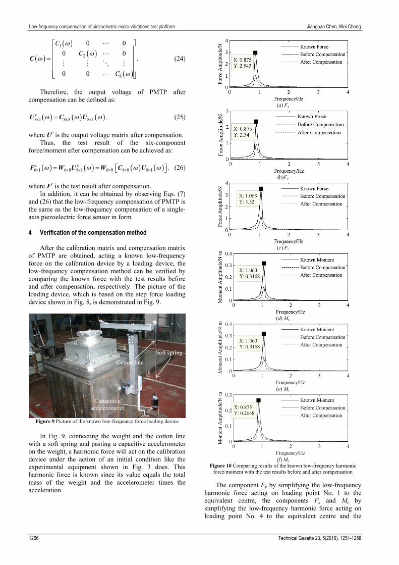
After the calibration matrix and compensation matrix of PMTP are obtained, acting a known low-frequency force on the calibration device by a loading device, the low-frequency compensation method can be verified by comparing the known force with the test results before and after compensation, respectively. The picture of the loading device, which is based on the step force loading device shown in Fig. 8, is demonstrated in Fig. 9.
Figure 9 Picture of the known low-frequency force loading device
In Fig. 9, connecting the weight and the cotton line
with a soft spring and pasting a capacitive accelerometer on the weight, a harmonic force will act on the calibration device under the action of an initial condition like the experimental equipment shown in Fig. 3 does. This harmonic force is known since its value equals the total mass of the weight and the accelerometer times the acceleration.
(a) Fx
(b)Fy
(c) Fz
(d) Mx
(e) My
(f) Mz
Figure 10 Comparing results of the known low-frequency harmonic force/moment with the test results before and after compensation
The component Fy by simplifying the low-frequency harmonic force acting on loading point No. 1 to the equivalent centre, the components Fx and Mz by simplifying the low-frequency harmonic force acting on loading point No. 4 to the equivalent centre and the
Soft spring
Cotton line
Capacitive accelerometer

Jiangpan Chen, Wei Cheng Kompenzacija niske frekvencije probne platforme s piezoelektričnim mikro vibracijama
Tehnički vjesnik 23, 5(2016), 1251-1258 1257
components Fz, Mx and My by simplifying the low-frequency harmonic force acting on loading point No. 9 to the equivalent centre are used to indicate the performance of the low-frequency compensation of PMTP. The soft spring used to act low-frequency harmonic force on loading point No. 9 is different to it used to act force on loading point No. 1 and No. 4, which is to show the compensation performance in different frequencies. The comparing results of the known low-frequency harmonic force/moment with the test results before and after compensation are shown in Fig. 10.
The vibration amplitudes of the known harmonic force/moment and the test results before and after compensation are shown in Tab. 1.
Table 1 Vibration amplitudes
Component Known
force/moment Before
compensation After
compensationFx/N 2,943 1,081 3,147 Fy/N 2,340 0,976 2,236 Fz/N 3,520 1,200 3,592
Mx/N·m 0,317 0,121 0,335 My/N·m 0,317 0,125 0,338 Mz/N·m 0,265 0,133 0,253
The vibration amplitude test errors of PMTP at the same vibration frequency in low frequency band before and after compensation are shown in Fig. 11.
Figure 11Test errors of PMTP before and after compensation
The conclusions obtained by observing Fig. 10, Tab. 1 and Fig. 11 are as follows: 1) The frequency of the known harmonic force acting on
loading point No. 1 and No. 4 is 0,875 Hz and the frequency of the known harmonic force acting on loading point No. 9 is 1,063 Hz. Both are in low frequency band.
2) The PMTP discussed in this paper is able to test the vibration frequency precisely either before compensation or after compensation.
3) The test results of the vibration amplitudes before compensation are quite different from the known force/moment, but they are almost consistent with the known force/moment after compensation. The test errors of PMTP after compensation decrease sharply from those before compensation. Therefore, in Fig. 10, the line for ‘After Compensation’ is covered by the line for ‘Known Force/Moment’, and cannot be seen apparently.
4) The compensation method proposed in this paper can effectively compensate the performance of PMTP in low frequency band.
5 Conclusion
In this paper, the low-frequency compensation method of PMTP, based on the low-frequency compensation method of a single-axis piezoelectric force sensor, is proposed. The performance of this low-frequency compensation method is verified by experimental test. The results show that this low-frequency compensation method can effectively compensate the performance of PMTP in low frequency band. All the conclusions obtained from this paper make the precise test of the low-frequency micro-vibrations, generated by the rotary equipment on spacecraft, come true on the earth. 6 References [1] Kamesh, D.; Pandiyan, R.; Ghosal, A. Modeling, design
and analysis of low frequency platform for attenuating micro-vibration in spacecraft. // Journal of Sound and Vibration. 329, 17(2010), pp. 3431-3450. DOI: 10.1016/j.jsv.2010.03.008
[2] Zhang, P. F.; Cheng, W.; Zhao, Y. Measure of reaction wheels disturbance considering coupling effect. // Journal of Beijing University of Aeronautics and Astronautics. 37, 8(2011), pp. 948-952.
[3] Chen, J. P.; Cheng, W.; Han, W. Analysis and simulation of stepper motor disturbance considering structural coupling. // Applied Mechanics and Materials. 526, (2014), pp. 103-108. DOI: 10.4028/www.scientific.net/AMM.526.103
[4] Chen, J. P.; Cheng, W.; Wang, Y. F. Modeling and simulation of solar array drive assembly disturbance driving a flexible load. // Applied Mechanics and Materials. 565, (2014), pp. 67-73. DOI: 10.4028/www.scientific.net/AMM.565.67
[5] Zhang, P. F.; Cheng, W.; Wang, H. Disturbance modeling and parameters identification of reaction wheel assembly on spacecraft. // Journal of Beijing University of Aeronautics and Astronautics. 36, 7(2010), pp. 879-882.
[6] Masterson, R. A.; Miller, D. W. Development and validation of empirical and analytical reaction wheel disturbance models, Massachusetts Institute of Technology, 1999.
[7] Masterson, R. A.; Miller, D. W.; Grogan, R. L. Development and validation of reaction wheel disturbance models: Empirical Model. // Journal of Sound and Vibration. 249, 3(2002), pp. 575-598. DOI: 10.1006/jsvi.2001.3868
[8] Kamesh, D.; Pandiyan, R.; Ghosal, A. Passive vibration isolation of reaction wheel disturbances using a low frequency flexible space platform. // Journal of Sound and Vibration. 331, 6(2012), pp. 1310-1330. DOI: 10.1016/j.jsv.2011.10.033
[9] Zhou, W. Y.; Li, D. X.; Luo, Q. Analysis and testing of micro vibrations produced by momentum wheel assemblies. // Chinese Journal of Aeronautics. 25, 4(2012), pp. 640-649. DOI: 10.1016/S1000-9361(11)60430-5
[10] Luo, Q.; Li, D. X.; Zhou, W. Y. Dynamic modelling and observation of micro-vibrations generated by a Single Gimbal Control Moment Gyro. // Journal of Sound and Vibration. 332, 19(2013), pp. 4496-4516. DOI: 10.1016/j.jsv.2013.03.034
[11] Zhou, W. Y.; Li, D. X. Experimental research on a vibration isolation platform for momentum wheel assembly. // Journal of Sound and Vibration. 332, 5(2013), pp. 1157-1171. DOI: 10.1016/j.jsv.2012.10.027
[12] Cheng, Q. H.; Li, Y. X. Design for low-frequency compensation of piezoelectric sensor based on digital filter.
Fx Fy Fz Mx My Mz

Low-frequency compensation of piezoelectric micro-vibrations test platform Jiangpan Chen, Wei Cheng
1258 Technical Gazette 23, 5(2016), 1251-1258
// Electronic Measurement Technology. 30, 8(2007), pp. 143-146.
[13] Liu, X. Y.; Zhang, P.; Han, Z. H. Application of dynamic compensation method to static calibration of piezoelectric sensors. // Chinese Journal of Scientific Instrument. 25, 4(2004), pp. 9-10.
[14] Gao, Q. Q. Study on digital compensation method for the dynamics of piezoelectric sensor. // Piezoelectric & Acousto-optic. 34, 4(2012), pp. 557-560.
[15] Liu, X. Y.; Zhang, P.; Han, Z. H. Research on the identification algorithm for time constant of piezoelectric sensor. // Chinese Journal of Scientific Instrument. 27, 6(2006), pp. 1667-1668.
[16] Chen, J. P.; Cheng, W.; Xia, M. Y. An ultra-low frequency micro-vibration testing platform based on strain-resistance effect. // Journal of Vibration and Shock. 33, 24(2014), pp. 77-81.
Authors’ addresses Jiangpan Chen, PhD student School of Aeronautic Science and Engineering, Beijing University of Aeronautics and Astronautics, Xueyuan Road No. 37, Haidian District, Beijing 100191, China E-mail: [email protected] Wei Cheng, Professor School of Aeronautic Science and Engineering, Beijing University of Aeronautics and Astronautics, Xueyuan Road No. 37, Haidian District, Beijing 100191, China E-mail: [email protected]