28-1 Design of Anchored Sheet Pile Wall in Granular Soil-2 23052014
Upload
trinhtuyenCategory
view
222download
3
Document No. 31629-13-RPT-0004 Rev. A
LOW ACTIVITY WASTE PRETREATMENT SYSTEM
Project No. 31269 (T5L01)
Document No. 31269-13-RPT-0004
Safety Related Non-Safety Related
Evaluation of Excavation Retaining Methods
Prepared for Washington River Protection Solutions, LLC
Revision: A Status: Preliminary
Document No. 31629-13-RPT-0004 Rev. A
Page ii of v
REVISION PAGE
Project Name: LAWPS Discipline: Structural Client: Washington River Protection Solutions Project Number: 31269 (T5L01) Latest Revision:A
Revision Signatures
Prepared by Duane E Castaneda
Date Approved by (SDE) Steven Fenner
Date
Checked by James Klett
Date Approved by (QA) Paul Bell
Date
Verified by (if required) Date Approved by (PEM)
Brianna Atherton Date
Status Rev. No.
Date Prepared By Pages Description of Changes
Preliminary A Preliminary Issue
Safety Related
Yes No
Quality Level
FQA EQA CQA

Document No. 31629-13-RPT-0004 Rev. A
Page iii of v
EXECUTIVE SUMMARY A soldier pile and lagging earth retaining system (ERS) with tie-backs is selected as an option for LAWPS vault excavation in lieu of a full excavation with sloping sides at a constant slope . This system was selected based on cost, schedule, and feasibility considering site conditions. Calculations were performed to provide a preliminary design shown in Attachment D, Figure D-2. The study also produced a shoring excavation plan that is shown in Attachment D, Figure D-1. The excavation plan has an operating pad for an excavator to remove soil from excavation and place it in a dump truck on the access road. The access road runs south and east of the excavation allowing other LAWPS facilities to be constructed while the vault is constructed. Pending is a decision whether the ERS may be used as a form for the vault exterior concrete walls. An advantage of using the shoring excavation approach is that less area would be dedicated to the excavation. This would allow construction of other LAWPS facilities while the vault is under construction. Also, less soil removal, storage, and compaction would be required for the shoring excavation versus a cut only excavation.

Document No. 31629-13-RPT-0004 Rev. A
Page iv of v
TABLE OF CONTENTS
1.0 INTRODUCTION .............................................................................................................. 1
2.0 PURPOSE AND SCOPE .................................................................................................... 1
3.0 ASSUMPTIONS AND OPEN ITEMS ............................................................................... 1
3.1 ASSUMPTIONS ..................................................................................................... 1
3.2 OPEN ITEMS ......................................................................................................... 1
4.0 SELECTION OF EARTH RETAINING SYSTEMS ......................................................... 2
4.1 EARTH RETAINING SYSTEMS CONSIDERED ............................................... 2
4.2 EARTH RETAINING SYSTEMS COSTS ............................................................ 2
4.3 SELECTION OF EARTH RETAINING SYSTEM FOR LAWPS ....................... 3
5.0 DESIGN OF THE EARTH RETAINING SYSTEM ......................................................... 3
5.1 DESIGN OF SOLDIER PILE AND LAGGING ERS ........................................... 3
5.2 ONE-SIDED OR TWO-SIDED FORMS FOR THE VAULT EXTERIOR WALLS ............................................................................................................................... 6
6.0 PROPOSED EXCAVATION PLAN ................................................................................. 6
7.0 COST AND SCHEDULE FOR SELECED ERS ............................................................... 7
8.0 RESULTS ........................................................................................................................... 7
9.0 CONCLUSION AND RECOMMENDATIONS ............................................................... 7
10.0 REFERENCES ................................................................................................................... 8
ATTACHMENT A. SHORING SYSTEM DESCRIPTIONS .................................................... A1
ATTACHMENT B. MINUTES OF MEETINGS ........................................................................ B1
ATTACHMENT C. EMAILS: ..................................................................................................... C1
ATTACHMENT D. CIVIL PLAN OF EXCAVATION WITH PROPOSED EARTH RETAINING SYSTEM ............................................................................................................... D1
ATTACHMENT E. CONCEPTUAL DESIGN EXCAVATION PLAN ..................................... E1
ATTACHMENT F. EXCAVATOR USED IN ERS CALCULATIONS .................................... F1
ATTACHMENT G. ERS CALCULATIONS ............................................................................. G1
Document No. 31629-13-RPT-0004 Rev. A
Page v of v
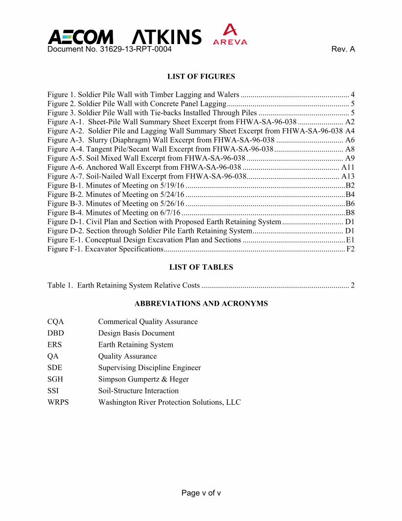
LIST OF FIGURES
Figure 1. Soldier Pile Wall with Timber Lagging and Walers ....................................................... 4 Figure 2. Soldier Pile Wall with Concrete Panel Lagging .............................................................. 5 Figure 3. Soldier Pile Wall with Tie-backs Installed Through Piles .............................................. 5 Figure A-1. Sheet-Pile Wall Summary Sheet Excerpt from FHWA-SA-96-038 ....................... A2 Figure A-2. Soldier Pile and Lagging Wall Summary Sheet Excerpt from FHWA-SA-96-038 A4 Figure A-3. Slurry (Diaphragm) Wall Excerpt from FHWA-SA-96-038 .................................. A6 Figure A-4. Tangent Pile/Secant Wall Excerpt from FHWA-SA-96-038 ................................... A8 Figure A-5. Soil Mixed Wall Excerpt from FHWA-SA-96-038 ................................................. A9 Figure A-6. Anchored Wall Excerpt from FHWA-SA-96-038 ................................................. A11 Figure A-7. Soil-Nailed Wall Excerpt from FHWA-SA-96-038 ............................................... A13 Figure B-1. Minutes of Meeting on 5/19/16 ................................................................................. B2 Figure B-2. Minutes of Meeting on 5/24/16 ................................................................................. B4 Figure B-3. Minutes of Meeting on 5/26/16 ................................................................................. B6 Figure B-4. Minutes of Meeting on 6/7/16 ................................................................................... B8 Figure D-1. Civil Plan and Section with Proposed Earth Retaining System ............................... D1 Figure D-2. Section through Soldier Pile Earth Retaining System .............................................. D1 Figure E-1. Conceptual Design Excavation Plan and Sections .................................................... E1 Figure F-1. Excavator Specifications ............................................................................................ F2
LIST OF TABLES
Table 1. Earth Retaining System Relative Costs ........................................................................... 2
ABBREVIATIONS AND ACRONYMS
CQA Commerical Quality Assurance
DBD Design Basis Document
ERS Earth Retaining System
QA Quality Assurance
SDE Supervising Discipline Engineer
SGH Simpson Gumpertz & Heger
SSI Soil-Structure Interaction
WRPS Washington River Protection Solutions, LLC
Document No. 31629-13-RPT-0004 Rev. A
Page 1 of 8
1.0 INTRODUCTION Conceptual design for LAWPS shows a cut and fill excavation from grade elevation to an elevation at the lowest vault basemat elevation (see Attachment E, Figure E-1). This requires removal, storage, and compaction of a substantial amount of soil. Also, this approach requires a large area dedicated to the excavation until the vault exterior walls are constructed and the area is backfilled. This has led to the consideration of an alternate approach where a shoring system is installed around the vault area and soil is excavated only within the area bounded by the shoring walls. This would allow work to be performed on other parts of the LAWPS facility that would otherwise be inaccessible if the cut and fill excavation approach was used. 2.0 PURPOSE AND SCOPE This study identifies excavation and earth retaining systems (ERS) and provides recommendations for the LAWPS vault structure per the Prejob Brief Meeting (31269-02-PJB-0193). Considerations for selection of method include:
1. Technical adequacy 2. Impact on concrete design 3. Excavation area/volume 4. Schedule 5. Cost
This study documents coordination meetings with Washington River Protection Solutions (WRPS) and geotechnical consultant Shannon and Wilson held to evaluate construction impacts and coordinate development of estimates as necessary to determine relative costs associated with this study. 3.0 ASSUMPTIONS AND OPEN ITEMS 3.1 Assumptions
1. Design of the earth retaining system for seismic forces is not required due to period of construction.
2. The soldier piles will be driven and not installed in drilled holes.
3.2 Open Items
1. Discussion with SGH regarding the impact of the ERS on the soil-structure interaction analysis. This may determine whether the ERS is permanent or temporary.
2. Costs of the designed soldier pile wall have not been estimated. Tom Goedjen, WRPS, said that he has estimators who can estimate costs for the selected ERS.
3. The schedule and estimated duration for installing the ERS has not been determined.

Document No. 31629-13-RPT-0004 Rev. A
Page 2 of 8
4. Drawing H-16-000201 shows waste transfer piping routed to the south end of the LAWPS vaults. Although the specific routing of the lines is on hold, penetrations in the lagging for these lines are necessary.
5. The effect of surcharge loading on the ERS due to adjacent structures has not been evaluated.
4.0 SELECTION OF EARTH RETAINING SYSTEMS
4.1 Earth Retaining Systems Considered The following earth retaining systems were initially considered:
1. Sheet pile wall with tie backs.
2. Soldier pile and lagging wall with tie backs.
3. Slurry (diaphragm) wall with tie backs
4. Tangent pile/secant pile wall with tie backs
5. Soil mixed wall with tie-backs.
6. Soil-nailed wall Descriptions of these systems are shown in Attachment A, which contains excerpts from FHWA-SA-96-038. 4.2 Earth Retaining Systems Costs
Table 1. Earth Retaining System Relative Costs
Earth Retaining System Cost
(1995 dollars/square meter) Sheet Pile Wall $160-$430 Soldier Pile and Lagging Wall $110-$380 Slurry (Diaphragm) Wall $650-$930 Tangent Pile/Secant Pile Wall $430-$810 Soil Mixed Wall $430-$590 Anchored Wall $160-$810 Soil Nailed Wall $160-$600
Costs for ERS’s shown in Table 1 as 1995 costs per square meter are taken from FHWA-SA-96-038. They provide a rough guide as to relative costs of the various ERS.

Document No. 31629-13-RPT-0004 Rev. A
Page 3 of 8
4.3 Selection of Earth Retaining System for LAWPS During the first meeting (see 5/19/16 meeting notes in Attachment B) it was decided that the feasible ERS’s for the LAWPS site are:
1. Sheet pile wall with tie backs.
2. Soldier pile and lagging wall with tie backs.
3. Soil-nailed wall Table 1 shows that these are the least cost ERS’s. In subsequent meetings, Clint Wilson from Shannon and Wilson recommended that the in situ cohesionless soil would make the soil-nailed wall infeasible (see 5/24/16 meeting notes in Attachment B). Also, in situ soil conditions would allow sheet piles to be driven to a maximum depth of 20 ft (see 5/26/16 meeting notes in Attachment B) while the vault excavation would require driving piles to a depth greater than 46 ft. Therefore, it was concluded that soldier pile and lagging wall with tie backs would be feasible and the preferred ERS. 5.0 DESIGN OF THE EARTH RETAINING SYSTEM 5.1 Design of Soldier Pile and Lagging ERS Preliminary design of the soldier piles, tie-backs, and walers is shown in Figure D-2 in Attachment D. Structural calculations showing adequacy of the design are shown in Attachment G. These calculations were performed using preliminary soil information provided by Shannon and Wilson (see email dated 6/7/16 in Attachment C) and in accordance with the Design Basis Document. Construction of the soldier pile and lagging wall begins with driving soldier piles down to their final depth. Alternately, soldier piles may be placed in drilled holes, which are then backfilled with soil or concrete. For this study it was assumed that soldier piles would be driven. Also, steel HP sections are used for the soldier piles for this study. These steel sections are similar to wide flange (I-shaped) sections except that the flange width exceeds the depth. Excavation begins after installation of the soldier piles. Lagging is installed between the soldier piles as the excavation proceeds. The lagging can be wood timbers as shown in Figure 1 if the wall is temporary or using concrete panels as shown in Figure 2 if the wall is permanent. Tie-backs and walers are installed when the excavation reaches about 3 ft. below the tie-back elevation (see Figure 1). Tie-backs are soil anchors which may consist of a single steel rod or steel tendons. As shown in Attachment D, Figure D-2, the anchors are grouted for length of the anchor called the bond zone a certain distance behind the potential failure plane.

Document No. 31629-13-RPT-0004 Rev. A
Page 4 of 8
Calculations shown in Attachment G show that HP16x88 soldier piles spaced at 8’-0” o.c. are adequate for the vault excavation. Three rows of tie-back anchors are required each with a 145 kip design. These tie-backs would not require unusually heavy or specialized equipment according to FHWA-IF-99-015, Sect. 5.3. In addition, the anchor bond length of 34’-0” does not exceed the maximum 40’-0” recommended by FHWA-IF-99-015. The horizontal tie-back spacing is 8’-0” o.c. Since the horizontal tie-back spacing is the same as the soldier pile spacing, tie-backs could be installed through the soldier piles. A steel circular tube stiffener or other type of stiffener would be welded to the soldier pile as shown in Figure 3. Alternately, tie-backs could be anchored by walers running horizontally across the soldier piles as shown in Figure 1. Structural calculations indicate that back-to-back MC18x51.9 steel sections would be required for the walers. The ERS has been designed to support the heaviest equipment that may be used near the wall. The maximum equipment loads are shown in the email dated 6/8/16 shown in Attachment C. The maximum load is due to a excavator. The excavator used to design the wall is a Caterpillar 325 F with an operating weight of 116,600 lbf. Specifications for the excavator are shown in Attachment F. The track hoe is allowed to be placed a minimum 5 ft. distance from the track centerline to the wall. This minimum distance also applies to other equipment listed in the email dated 6/8/16.
Figure 1. Soldier Pile Wall with Timber Lagging and Walers

Document No. 31629-13-RPT-0004 Rev. A
Page 5 of 8
Figure 2. Soldier Pile Wall with Concrete Panel Lagging
Figure 3. Soldier Pile Wall with Tie-backs Installed Through Piles

Document No. 31629-13-RPT-0004 Rev. A
Page 6 of 8
5.2 One-Sided or Two-Sided Forms for the Vault Exterior Walls The possibility of using the excavation support system as a form for the vault exterior walls was discussed (see Attachment B, 5/24/16 Minutes of Meeting). This could speed-up construction of the exterior walls and save forming costs. However, this is an open item pending discussions with SGH about the impact of the ERS on the soil-structure interaction (SSI) analysis. The SSI analysis may require the ERS to be temporary so that the ERS would not be used as a form. This would require 1) detensioning the tie-backs and 2) removal of the timber lagging as backfill is placed after which the ERS would no longer function. Using the earth retaining system as a permanent form would require design of the tie-backs to resist seismic earth pressure loads and seismic forces due to the exterior vault concrete wall self-weight. The ERS shown in Figure D-2 has not been designed for seismic loads. Also, as discussed previously a permanent ERS may require concrete lagging as opposed to degradable timbers, which would increase costs. 6.0 PROPOSED EXCAVATION PLAN The proposed shoring excavation plan and section is shown in Attachment D, Figure D-1. This plan was developed assuming that the ERS would be used as a form for the exterior vault concrete walls. If the ERS is not used as a form for the vault walls, then the excavation area would be widened by about 5 ft. The excavation plan (Figure D-1) shows two bottom of excavation elevations levels since the vault has two basemat elevations. An excavator operation pad is provided. A excavator will operate off this pad to remove soil from the inside the excavation and place the soil in a dump truck adjacent to it on the access road. Two scaffold stairs are shown in the main excavation area at diametrically opposed corners. The stairs would be increased in height as the excavation proceeded to deeper elevations. Having the stairs inside the excavation could require placing the basemat in two pours. For the first pour, the stairs would be placed in an area where concrete is not placed. For the second pour, the stairs would be moved to the area of the basemat already placed and ready to accept construction loads. Alternately, legs of stairs could be supported on embeds in the basemat. This would allow the basemat to be placed in one pour. These embed would have to be carefully planned so as not to interfere with embeds required to support equipment. Stairs would also be required at the bottom of the shallower excavation area. They are not shown on Figure D-1. The access road is shown running south and then east of the excavation. This road alignment allows construction of other LAWPS facilities to proceed, while the vault is constructed. The access road is shown on Figure D-1 as running northward to the existing WTP Loop Road. However, this road may be adjusted to run slightly east of straight northward to provide better access to areas where other LAWPS facilities will be constructed.

Document No. 31629-13-RPT-0004 Rev. A
Page 7 of 8
7.0 COST AND SCHEDULE FOR SELECED ERS Cost and impact on the project baseline for this activity are TBD pending closure of open items identified in section 3.2. 8.0 RESULTS A soldier pile and lagging earth retaining system (ERS) has been selected for the LAWPS vault excavation. This system was selected based on cost and technical adequacy. A soil nailed ERS was not selected due poor capacity in the cohesionless in situ soils at the site. Also, a sheet pile wall ERS was not selected since sheet piling can only be driven to a maximum 20 ft. depth, while the vault excavation would require driving the sheet piling to greater than 46 ft. in depth. Calculations shown in Attachment G were performed to determine the required soldier piles, tie-backs, and walers. Details for the soldier pile wall are shown in Figure D-2 in Attachment D. HP16x88 soldier piles spaced at 8’-0” o.c. are adequate for vault excavation shown in Figure D-1. Three rows of tie-back anchors are required with a design capacity of 145 kip each. In addition, the required 34’-0” anchor bond length does not exceed the maximum 40’-0” recommended by FHWA-IF-99-015. Tie-backs could be installed through the soldier pile section or they could be anchored to walers running horizontally outside of the soldier piles. Structural calculations indicate that back-to-back MC18x51.9 steel section walers are required. The maximum equipment load allowed near the wall is a 116,600 lb excavator shown in Attachment F with the track centerline located a minimum 5 ft from the wall. The ERS could be used as a form for the vault exterior concrete walls. This would reduce forming costs and eliminate bracing of the walls during backfilling operations. The ERS would be permanent and may require concrete panel lagging. This configuration would require that tie-backs resist seismic earth pressures and seismic loads due the wall self-weight. In addition, it may pose problems for the SSI analysis. A shoring excavation plan using the selected ERS is shown in Figure D-1, Attachment D. This plan assumes that the ERS will be used as a form for the vault exterior walls. Two scaffold stairs are required in the excavation area. The plan shows a operation pad for an excavator. The excavator would remove soil from the excavation area and place it in a dump truck on the access road. The access road runs south and east of the excavation area. This allows access to most of the LAWPS site so other LAWPS facilities can be constructed while excavation and construction of the vault proceeds. 9.0 CONCLUSION AND RECOMMENDATIONS This study selected an earth retaining system (ERS) based on feasibility due to site soil conditions and cost. The ERS selected is a soldier pile and lagging wall with tie-backs. Calculations were performed to determine the required steel soldier pile section and spacing. Also, the required vertical spacing of the tie-backs and design capacities were determined. The steel section for the walers was determined.

Document No. 31629-13-RPT-0004 Rev. A
Page 8 of 8
It is recommended to discuss the proposed system with SGH who will be performing the SSI analysis. Also, if the selected ERS is to be permanent and provide a form for the exterior vault concrete walls, then further calculations would be required to determine the effect of seismic forces on the ERS. 10.0 REFERENCES
4.1. FHWA-SA-96-038, Earth Retaining Systems, Geotechnical Engineering Circular No.2, 1996.
4.2. FHWA-IF-99-015, "Ground Anchors and Anchored Systems", Geotechnical Engineering Circular No. 4, June 1999.
4.3. 31269-22-DBD-001, Design Basis Document, Rev. 0 (Pending 06/16/16).
4.4. 31269-02-PJB-0193, Rev. 0, Develop White Paper Documenting Recommended Excavation Approach.
4.5. H-16-000201, Rev. A, Enlarged Site Plan.

Document No. 31629-13-RPT-0004 Rev. A
Page A1 of A14
ATTACHMENT A. SHORING SYSTEM DESCRIPTIONS

Document No. 31629-13-RPT-0004 Rev. A
Page A2 of A14
Figure A-1. Sheet-Pile Wall Summary Sheet Excerpt from FHWA-SA-96-038

Document No. 31629-13-RPT-0004 Rev. A
Page A3 of A14

Document No. 31629-13-RPT-0004 Rev. A
Page A4 of A14
Figure A-2. Soldier Pile and Lagging Wall Summary Sheet Excerpt from FHWA-SA-96-038

Document No. 31629-13-RPT-0004 Rev. A
Page A5 of A14

Document No. 31629-13-RPT-0004 Rev. A
Page A6 of A14
Figure A-3. Slurry (Diaphragm) Wall Excerpt from FHWA-SA-96-038

Document No. 31629-13-RPT-0004 Rev. A
Page A7 of A14

Document No. 31629-13-RPT-0004 Rev. A
Page A8 of A14
Figure A-4. Tangent Pile/Secant Wall Excerpt from FHWA-SA-96-038

Document No. 31629-13-RPT-0004 Rev. A
Page A9 of A14
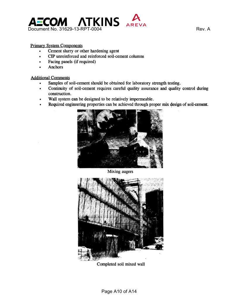
Figure A-5. Soil Mixed Wall Excerpt from FHWA-SA-96-038
Document No. 31629-13-RPT-0004 Rev. A
Page A10 of A14

Document No. 31629-13-RPT-0004 Rev. A
Page A11 of A14
Figure A-6. Anchored Wall Excerpt from FHWA-SA-96-038