
Loudspeakers and acoustic enclosures · The four main loudspeaker parameters The performance of the...
16
SWISS AUDIO MANUFACTURE www.jeanmaurer.ch Loudspeakers and acoustic enclosures Short illustrated description of speaker technologies and the challenges placed on them August 2016 Copyright © 2016 by Jean Maurer Swiss Audio Manufacture SA, Aubonne Reproducon in part or in whole is permied if the original source is quoted Translated from the original French text by: Suter Consulng, Berne & Pully
Transcript of Loudspeakers and acoustic enclosures · The four main loudspeaker parameters The performance of the...

SWISS AUDIO MANUFACTURE
Copyright © 2016 by Jean Maurer Swiss Audio Manufacture SA, AubonneReproduc�on in part or in whole is permi�ed if the original source is quoted
www.jeanmaurer.ch
1
Loudspeakers and acoustic enclosuresShort illustrated description of speaker technologies and the challenges placed on them
August 2016
Copyright © 2016 by Jean Maurer Swiss Audio Manufacture SA, AubonneReproduc�on in part or in whole is permi�ed if the original source is quoted
Translated from the original French text by:Suter Consul�ng, Berne & Pully

SWISS AUDIO MANUFACTURE
2Copyright © 2016 by Jean Maurer Swiss Audio Manufacture SA, Aubonne
Reproduc�on in part or in whole is permi�ed if the original source is quoted
www.jeanmaurer.ch
Human physiological sensitivity
Human physiological sensi�vity is the basis of all constraints on the reproduc�on of high-fidelity music. This
sensi�vity is not linear; neither as far as frequency nor as far as amplitude is concerned.
Between 78 and 102 decibel (dB), a 30 year old person can s�ll hear sound signals with frequencies between
20 and 20,000 Hz. When ge�ng older, people's ears lose some sensi�vity at higher frequencies; at over 60
years of age, frequencies above 12 or 14 kHz are a�enuated, but not completely lost. During a concert, a
music lover of this age hears the music with the ears of his or her age. However, the analysis system of his or
her brain has be�er abili�es than the majority of 20-year-old persons. This cultural ability allows him or her
to know how to listen be�er, even if he or she actually hears less well. We could say that we hear with our
ears but listen with our brain. Or we could say - forgive this comparison - that our ears are comparable to
hardware (microphones) which ages over the years, and that our brain works thanks to con�nually updated
so�ware that has been culturally acquired.
Our physiological sensi�vity is thus not linear as far as frequency is concerned, far from it. There is a zone of
hypersensi�vity located around 1,400 Hz. The frequency range of 2 octaves around 1,400 Hz, i.e. 700 to
2,800 Hz, is a "sacred area", where even the most draconian measures must be taken to reduce any form of
distor�on in the reproduc�on of the sound (distor�ons, decay-�me broadening and direc�onal error).
This frequency range therefore requires, as far as possible, the design of an acous�c enclosure star�ng from
and around its midrange loudspeaker. We require extremely precise work from this loudspeaker, whilst
taking into account that the field of ac�vity is reduced to just these 2 octaves. In order to complete the
spectral reproduc�on as a whole, the acous�c system must be complemented with a bass-frequency
speaker (woofer) and a high-frequency speaker (tweeter). Consequently, a high-performance acous�c
enclosure must be fi�ed with no more (or less) than three speakers to be a real sound reproduc�on system.
100
120
60
80
40
20
0
140
Frequency
Hearing range of human physiology
20Hz
30
Leve
l dB
50 100 200 300 500 1kHz
20kHz
2 3 5 10
Ph
ysio
logi
cal s
ensi
tivi
ty t
o s
ou
nd
dis
tort
ion
(n
o u
nit
)
Frequency
Hypersensitivity zone of human physiology centred at 1,400 Hz
20Hz
30 50 100 200 300 500 1kHz
20kHz
2 3 5 10
SWISS AUDIO MANUFACTURE
Copyright © 2016 by Jean Maurer Swiss Audio Manufacture SA, AubonneReproduc�on in part or in whole is permi�ed if the original source is quoted
www.jeanmaurer.ch
3
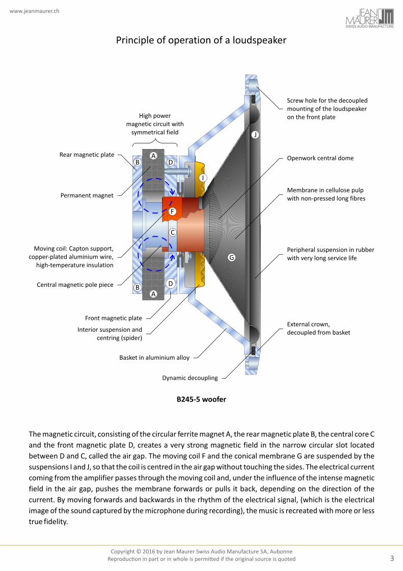
Principle of operation of a loudspeaker
The magnetic circuit, consisting of the circular ferrite magnet A, the rear magnetic plate B, the central core C
and the front magnetic plate D, creates a very strong magnetic field in the narrow circular slot located
between D and C, called the air gap. The moving coil F and the conical membrane G are suspended by the
suspensions I and J, so that the coil is centred in the air gap without touching the sides. The electrical current
coming from the amplifier passes through the moving coil and, under the influence of the intense magnetic
field in the air gap, pushes the membrane forwards or pulls it back, depending on the direction of the
current. By moving forwards and backwards in the rhythm of the electrical signal, (which is the electrical
image of the sound captured by the microphone during recording), the music is recreated with more or less
true fidelity.
B245-5 woofer
High powermagnetic circuit with
symmetrical field
B
B
A
A
D
D
C
F
I
G
J
Permanent magnet
Moving coil: Capton support,copper-plated aluminium wire,
high-temperature insulation
Central magnetic pole piece
Front magnetic plate
Interior suspension andcentring (spider)
Basket in aluminium alloy
Dynamic decoupling
External crown,decoupled from basket
Peripheral suspension in rubberwith very long service life
Membrane in cellulose pulpwith non-pressed long fibres
Openwork central dome
Screw hole for the decoupledmounting of the loudspeakeron the front plate
Rear magnetic plate

SWISS AUDIO MANUFACTURE
4Copyright © 2016 by Jean Maurer Swiss Audio Manufacture SA, Aubonne
Reproduc�on in part or in whole is permi�ed if the original source is quoted
www.jeanmaurer.ch
The construction of an acoustic enclosureand the distribution of power load
An acoustic enclosure comprises three groups of elements
that are of equal importance for overall high-fidelity
performance:
- The loudspeakers, or transducers, which transform the
electrical signal from the amplifier into mechanical
movement and thus sound.
- The filters which direct the electrical signal to each of the
speakers, depending on the signal's frequency content
- The housing or, rather, the housings of the loudspeaker
system, which must treat the acoustic signals behind each
speaker (sound waves inside the enclosure created by the
membranes). This is in order to ensure that the back-wave
does not disturb the direct audible signal.
In the case of a symphonic orchestra, the largest portion of
the musical energy will be reproduced by the bass
loudspeaker (around 80%), which is responsible for the
depth of the musical image and its instrumental body. The
highest fidelity of reproduction is required from the
midrange transducer, which is responsible for the
intelligibility of the musical rendering. The sonic space is
provided by the treble loudspeaker from which the
highest reaction speed is required in order to reproduce
the signals well beyond 20 kHz.
0 100%
10%
1%
0.1%
0.01%
-10
-30
-40
Low
-mid
range
gra
die
nt
Hig
h-m
idra
nge g
radien
t
Bass g
radien
t
Frequency
In red, the distribution of orchestral power as a function of frequencyagainst energy transmitted by the filters to the three loudspeakers.
20Hz
30 50 100 200 300 500 1kHz
2 3 5 10 20kHz
bass transducer midrange treble
Pow
er r
atio
Att
enu
atio
n d
B
-20
Treb
le g
radie
nt
Frequency-separationfilters
BassMidrange
Treble
Power signal from the amplifier
Tweeter
Midrange loudspeaker
Woofer
Vent for bass reflex
Tuned housing

SWISS AUDIO MANUFACTURE
Copyright © 2016 by Jean Maurer Swiss Audio Manufacture SA, AubonneReproduc�on in part or in whole is permi�ed if the original source is quoted
www.jeanmaurer.ch
5
The four main loudspeaker parameters
The performance of the loudspeaker is proportional to:
In this equation, the compliance Cms is not involved.
η≈S · (B·l)²
m² · Redc
and Redc which is the DC resistance of the moving coil (F)
Tesla·metre[T·m]
millimetre/Newton[mm/N]
gram[g]
2S = π·r
metre²[m²]
From this formula, however, we can note that the moving mass has an influence proportional to the square
of its value: For example, in the case of the B245-5 speaker, with a moving mass of 33 grams, the
performance of the loudspeaker will be reduced by 6.15%, i.e. by 0.52 dB, if 1 gram too much of glue is used
during the mounting of the moving parts.
Force-factor: B·lThis corresponds to the magnetic field in
the air gap (circular slot located between C and D) multiplied by the length of the
winding of the moving coil immersed in this magnetic field
Mobile mass: m (commonly designated as Mms)
corresponds to the sum of the masses of the moving coil (F) + membrane (G)
+ part of suspensions (I+J) i.e. those that are in motion
Compliance: C(commonly designated as
Cms) corresponds to the sum of the elasticity of peripheral
suspensions (J) + internal centring (I)
Surface: Scorresponds to the total emissive surface, i.e. the
surface of the membrane (G) + part of the peripheral
suspension (J)
J
G
I
D
A
B B
A
D
I
Magnetic circuit
North pole ---> <--- South pole
South pole
North pole
South pole
North pole
Peripheral suspension Central openwork dome
Basket
Membrane
Spider (suspension)
Moving coil
F
C
SN
Direction ofmagnetic field
Mechanicalforce
Direction ofelectric current
SN
Direction ofmagnetic field
Mechanicalforce
Direction ofelectric current

SWISS AUDIO MANUFACTURE
6Copyright © 2016 by Jean Maurer Swiss Audio Manufacture SA, Aubonne
Reproduc�on in part or in whole is permi�ed if the original source is quoted
www.jeanmaurer.ch
Tuning the housing by the use of vents
φ
For extremely low frequencies, the vent transmits a lot of sound energy from inside the housing to its
exterior. This energy, which decreases with increasing frequency, becomes virtually zero above 250 Hz.
In comparison to a closed unit, a well calculated vented bass-reflex unit therefore allows a certain quan�ty
of energy to be recovered from the rear wave of the woofer in order to retrieve it to the listener's room (with
a favourable phase rela�on) and to a�enuate the extremely low frequencies that are barely audible and
harmful to the loudspeaker (resul�ng from an unfavourable phase rela�onship). This system therefore
allows the lineariza�on of the response at low frequencies.
Family of curves, for various vent variants in a 25-litre unit:A : closed unit (without vent)
: ideally tuned ventB : vent characteristic tuned to too high frequency = flattering, but very annoying in the long termC
20Hz
30 50 100 200 300 500 1kHz
2 3 5 10 20kHz
50
60
70
80
90
B
A
CFrequency Hz
C
A
Leve
l dB
oφ = 90 oφ = 0oφ > 90
Frequency
Leve
l dB
Example of a tuned, vented unit with a volume of 25 litresin comparison with a closed unit of the same volume
Level gained by the sum of front and rear sound waves with less than 90° phase shift
Level lost by the sum of front and rear sound waves with more than 90° phase shift
Enclosure with vent
Enclosure with vent
Sealed enclosure
Sealed enclosure
90
80
70
60
50
10Hz
1kHz
20 30 50 100 200 300 500

SWISS AUDIO MANUFACTURE
Copyright © 2016 by Jean Maurer Swiss Audio Manufacture SA, AubonneReproduc�on in part or in whole is permi�ed if the original source is quoted
www.jeanmaurer.ch
7
The basic criteria of the reproduction of bass frequencies
50
60
70
80
9093 dB --> -3 dB at 61 Hz90 dB --> -3 dB at 54 Hz87 dB --> -3 dB at 49 Hz
Frequency20Hz
30 50 100 200 300 500 1kHz
20kHz
2 3 5 10
Leve
l dB
/W a
t 1
m
Response characteristics for a given volume
For a particular volume: The efficiency and bandwidth are defined
50
60
70
80
90
Frequency20Hz
30 50 100 200 300 500 1kHz
20kHz
2 3 5 10
Leve
l dB
/W a
t 1
m
Response characteristics for given efficiency
92 dB/Wm
50 litres volume --> -3 dB at 35 Hz
35 litres volume --> -3 dB at 45 Hz
20 litres volume --> -3 dB at 55 Hz
For a particular efficiency:The volume and bandwidth are defined
For a particular bandwidth: The efficiency and volume are defined
50
60
70
80
90
Frequency20Hz
30 50 100 200 300 500 1kHz
20kHz
2 3 5 10
Leve
l dB
/W a
t 1
m
Response characteristics for a particular bandwidth
-3 dB at 40 Hz
60 litres volume --> efficiency 93 dB/Wm
40 litres volume --> efficiency 90 dB/Wm
20 litres volume --> efficiency 87 dB/Wm
4 - The maximum allowable level in decibels (dB)
5 - Other musical performance factors (distortions, decay-time broadening, etc.)
6 - The reliability (in load limiting and in aging)
1 - Efficiency (dB/W at 1m)
2 - Volume (litres) and the type of load (closed volume, vented system, or passive load)
3 - Bandwidth for extremely low frequencies
These three criteria for bass frequencies may not be allowed to contradict the fundamental rules of
physics, i.e.:

SWISS AUDIO MANUFACTURE
8Copyright © 2016 by Jean Maurer Swiss Audio Manufacture SA, Aubonne
Reproduc�on in part or in whole is permi�ed if the original source is quoted
www.jeanmaurer.ch
Conventional LC distribution filters
The bandpass filters transmit the signal coming from the amplifier to each of the speakers, depending on its
frequency content.
The high-performance passive filters with their steep a�enua�on gradients offer decisive advantages
compared to any other system. Consis�ng of self-induc�on coils with a large copper cross-sec�on and along
with no magne�c core, as well as of polypropylene capacitors, they are non-saturable and exhibit high
linearity as well as an excep�onally long service life.
Components of passive filters and their construction
Self-induction windingwith no core and very large cross-section:
1.68 mH - 0.11 Ω - 3 kg
Bandpass filters with steep attenuation gradients and low serial loss,without chemical capacitors and without magnetic cores
in the centre of the windings: 6.5 kg of components
Highly stable polypropylene capacitor:12.7 μF - 3 % - tgδ < 0.06 %
Tweeter
Medium
Woofer
Louspeaker input
+
-

SWISS AUDIO MANUFACTURE
Copyright © 2016 by Jean Maurer Swiss Audio Manufacture SA, AubonneReproduc�on in part or in whole is permi�ed if the original source is quoted
www.jeanmaurer.ch
9
0
-10
-20
-30
-40
20Hz
30 50 100 200 300 500 1kHz
2 3 5 10 20kHz
Frequency
Att
enu
atio
n d
B
Low
-mid
ran
ge g
rad
ien
t
Treb
le g
rad
ien
t
High
-mid
range grad
ient
Bass gradient
= Disturbed zones with JM 370E filters
0
-10
-20
-30
-40
20Hz
30 50 100 200 300 500 1kHz
2 3 5 10 20kHz
Frequency
Att
enu
atio
n d
B
Low
-mid
ran
ge g
rad
ien
t
Treb
le g
rad
ien
t
High
-mid
range grad
ient
Bass grad
ient
= Disturbed zones with 30 dB/octave filter gradients
0
-10
-20
-30
-40
Low-m
idrange gradient
Treble gradient
High-midrange gradient
Bass gradient
20Hz
30 50 100 200 300 500 1kHz
2 3 5 10 20kHz
Frequency
Att
enu
atio
n d
B
= Disturbed zones with 6 dB/octave filter gradients
A
DIn continuous, non-transitory operation mode, the series resistances between the amplifier and loudspeakers result in significant changes in bass response:
A: (theoretical case) 0 ΩB 0.5: (ideal case) ΩC 1: (correct) ΩD 3: (bad, but unfortunately too Ω often observed)
In a transitional regime (music), these series losses will generate a decay-time broadening / leading edge broadening between 50 and 300 Hz, which degrades (even more) the clarity of the musical message.
10Hz
1kHz
20 30 50 100 200 300 500
90
80
70
60
50
Leve
l dB
Frequency
Influence of resistive losses between amplifier and woofer on bass clarity
BC
The resistive losses of the bandpass filters and their consequences
The attenuation gradients of filters
The gradients of the filters determine common areas of loudspeaker operation. These areas are obviously disturbed by the influence of several loudspeakers that are physically dissimilar and at different locations. The steeper the gradients of the filters, the smaller will be the overlapping areas. The sound reproduction emitted by a particular loudspeaker membrane will therefore be more correct.

SWISS AUDIO MANUFACTURE
10Copyright © 2016 by Jean Maurer Swiss Audio Manufacture SA, Aubonne
Reproduc�on in part or in whole is permi�ed if the original source is quoted
www.jeanmaurer.ch
The impedance of the loudspeaker and acous�c enclosure:a very complex load and a big challenge for the amplifier
Like a hea�ng element, a resistance is a simple load. The current flowing through it depends on the voltage
that is applied to it; this current will be completely consumed and transformed into heat. This is valid
independent of the form of voltage applied.
An electric motor for alterna�ng current, or a loudspeaker, transforms electrical energy into mo�on with a
certain efficiency, dependent on the losses of the system. That part of the energy lost will be transformed
into heat. The part of the energy converted into movement presents a non-resis�ve but reac�ve load to the
voltage source. This implies, for reasons quite difficult to be simply explained, that this motor, or
loudspeaker, is going to request more current than the amount it will actually consume, and will return the
excess energy to the voltage source. This returned energy is called the electromo�ve counterforce (emcf).
Depending on the loudspeaker, current demand can exceed up to 7 �mes the energy required to move its
membrane. The excess energy has to travel back through the crossover filter and the loudspeaker's cables to
the amplifier. This propor�on of excess current returned depends on the content of electrical musical signal
(varia�ons in frequency and amplitude at each given moment). We can speak of a "dynamic cosine phi"
(cosφ).
When dimensioning the amplifier, the loudspeaker load presents two challenges:
- To provide sufficient current provision capacity: In ampere (A) and not in wa� (W). This ability will allow the
amplifier to avoid clipping the dynamic peaks of every large current demand coming from the loudspeaker
enclosure. Clipping is not only very unpleasant for the listener but dangerous for the health of the speakers
themselves.
- To have a good absorp�on capacity for the energy returning from the speakers (emcf). If this is not the case,
a rebound of current in the direc�on of the speakers will disrupt the spa�al acous�cs by having a very
detrimental echo effect. These dynamic "dips" will be drowned by this return of energy and musical detail
will be filled in with very unpleasant resonances, and even be �ring. The dynamics provided by the
amplifier/speaker system will become poor.
Certain transistor amplifiers are able to provide a lot of current. Their ability, for example, to accept a
resis�ve load of 2 ohms or even less is a pleasing feature in this regard. Those transistor amplifiers which
cannot operate with loads below 4 ohms should be eliminated as their designers have not understood what
a loudspeaker load actually represents.
By contrast, taking up the electromo�ve counterforce (emcf) causes many problems for the outputs of
direct transistor amplifiers, i.e. those without output transformers. The re-absorp�on of energy is poorly
controlled, with all the consequences already men�oned above.
The technology of tube-driven amplifiers requires an output transformer to adapt the working impedance
of the tubes to that of the speakers: The transformer is a component which is large, heavy, expensive and as
difficult to develop as to manufacture if one wants to have excellent performance. However, if correctly
dimensioned, it is a real gi� for the loudspeaker, which will be able to receive not only all the current needed
but also return − with a very good efficiency − this emcf, which will be short-circuited by the secondary
winding of the transformer. At the same �me, the low series resistance of the loudspeaker's filters and
cables facilitates the return of energy to the amplifier.
A few transistor amplifiers are fi�ed with output transformers and their quality can approach that of good
tube amplifiers.

SWISS AUDIO MANUFACTURE
Copyright © 2016 by Jean Maurer Swiss Audio Manufacture SA, AubonneReproduc�on in part or in whole is permi�ed if the original source is quoted
www.jeanmaurer.ch
11
Imp
edan
ce Ω
Apparent impedance of a woofer in free air
Frequency2
Hz3 5 10 20 30 50 100 200 300 500 1
kHz2
0
10
20
30
40
50
60
70
80
Imag
inar
y ax
is =
rea
ctiv
e im
ped
ance
Ω
40
30
20
10
0
10
20
30
40
Complex impedance of a woofer in free air
DC
0 10 20 30 40 50 60 70 80 90 100 110
Cap
acit
ive
imp
edan
ceIn
du
ctiv
e im
ped
ance
Real axis =
resistive impedance Ω
Imp
edan
ce Ω
Apparent impedance of a woofer in a bass-reflex enclosure
Frequency2
Hz3 5 10 20 30 50 100 200 300 500 1
kHz2
0
10
20
30
40
50
60
70
80
Imp
edan
ce Ω
Frequency2
Hz3 5 10 20 30 50 100 200 300 500 1
kHz2
0
10
20
30
40
50
60
70
80
Module of the impedance, between 20 and 20,000 Hz,of a speaker system of advanced technology: JM 370E
A theoretical pure resistance of 4 ohmsis represented by the blue horizontal line.
Pureresistance
of 4 Ω
Imag
inar
y ax
is =
rea
ctiv
e im
ped
ance
Ω40
30
20
10
0
10
20
30
40
Complex impedance of a woofer in a bass-reflex enclosure
DC
0 10 20 30 40 50 60 70 80 90 100 110
Cap
acit
ive
imp
edan
ceIn
du
ctiv
e im
ped
ance
Real axis =
resistive impedance Ω
20 kHz
F1F2Fs
"Nyquist" diagram of the JM 370E enclosure in the complex plane. The theoretical pure resistance of 4 ohms is represented by the blue spot at the centre of the diagram: The circles that originate from the blue spot
highlight the complexity of the actual load of an acoustic enclosure!
Imag
inar
y ax
is =
rea
ctiv
e im
ped
ance
Ω
40
30
20
10
0
10
20
30
40
0 10 20 30 40 50 60 70 80 90 100 110
Cap
acit
ive
imp
edan
ceIn
du
ctiv
e im
ped
ance
Real axis =
resistive impedance Ω
Pureresistance
of 4 Ω
The impedance of speakers and acoustic enclosures

SWISS AUDIO MANUFACTURE
12Copyright © 2016 by Jean Maurer Swiss Audio Manufacture SA, Aubonne
Reproduc�on in part or in whole is permi�ed if the original source is quoted
www.jeanmaurer.ch
The reac�ve energies of the loudspeaker,the killers of dynamics
The musical dynamic is defined by the amplitude difference between a peak and a dip of a modula�on
curve. To be exact, this represents the dynamics, expressed in decibel (dB).
It is fairly easy to reproduce a dynamic peak; it is far more difficult, however, to reproduce the dynamic drop
that follows, because a quan�ty of vibratory residues (of mechanical and electrical nature) will tend to
drown a musical signal of low amplitude. For example, a recording of a symphonic orchestra easily has 60 dB
of dynamics, in other words a power ra�o of 1 to 1,000,000. This difference in power has to be reproduced in
a frac�on of a second.
These parasi�cal residues (vibra�ons in the speaker box, electrical echoes, badly damped membranes, etc.)
obviously result when a for�ssimo is followed by a moment of very low intensity, some�mes even close to
silence (or, simply, a dynamic drop) and this drop should actually be reproduced at this precise instant. One
designates these signals which are indelicately prolonged as "the effects of decay-�me broadening". The
crux of the problem lies in what is called "the respect of silence".
In a loudspeaker, there are 3 major causes of decay-�me broadening:
1. The electromo�ve counterforce (emcf) of each of the loudspeakers is a parasite current inverse to the
electrical music signal from the amplifier. It has to be reabsorbed by the amplifier in the best possible way.
If this absorp�on goes wrong, an echo effect will result such as can be obtained in the mountains when
facing a rock wall: The original sound signal is rendered unintelligible by this reverbera�on. Now, the
amplifier's transistors can poorly absorb this return energy, which then is reflected back towards the
speakers and spoils the dynamics. If a tube amplifier is equipped with very good output transformers, the
secondary windings of the transformers short circuit these parasi�cal currents, and do this highly
efficiently.
2. The reac�ve mechanical energy caused by the movement of the loudspeaker components (winding and
membrane) and by the mass of the air around them gives rise to a form of parasi�c residue. These are
mechanical vibra�ons generated by the loudspeaker itself. In order to get around this, these vibra�ons
are transferred to the loudspeaker's enclosure by the frame of the loudspeaker's basket and excite the
various surfaces both with a delay and with considerable deforma�on. In Jean Maurer's loudspeaker
enclosures, these various residues are absorbed by the quartz sand, thanks in par�cular to the pre-
stressed threaded pin which dynamically connects the drive of the woofer to the sand-filled double back
of the enclosure, which has a very low resonance frequency. In addi�on, the loudspeaker's basket is
dynamically decoupled from the front of the loudspeaker's housing. For the midrange and treble
loudspeakers, the sand inserted in their double enclosures ensures this effect.
3. The movements of the loudspeaker's membrane produce a forward emission of sound and an inverse
emission of sound at its rear. This acous�c back-wave, the only form of unwanted signal which everyone is
talking about, is absorbed by the mineral wool. Part of this signal is taken up by the bass-reflex vent in
order to linearize the response at low frequencies. With respect to the previous two forms of reac�ve
energy, this is the one feature that presents the least amount of control problems as far as silence is
concerned. If the speaker's enclosure is very inert, i.e. has li�le resonance, the spa�al acous�c returned
will be good. The quartz sand contained in the double-back of the unit plays an important part in
providing this neutrality.

SWISS AUDIO MANUFACTURE
Copyright © 2016 by Jean Maurer Swiss Audio Manufacture SA, AubonneReproduc�on in part or in whole is permi�ed if the original source is quoted
www.jeanmaurer.ch
13
Active and reactive energies of the loudspeaker
Transmission of' reactive energyto the wall of the housingby the rigidly-fixed loudspeaker basket
Magnetic circuit
Basket
Moving coil
High mass:small displacements
Low mass:large displacements
Active electrical energy in the moving coil(musical signal coming from the amplifier)
Reactive electrical energy in the moving coil(electromotive counterforce returned to the amplifier)
Rear acoustic emission= reactive energy, inverse to the front wave (energy in the air)
Reactive mechanical energy(structure-borne energy = in the material)
Frontal acoustic emission= Active energy (energy in the air)
Active mechanical energy(movement energy)
Front plateof the enclosure
Membrane
Ori
gin
al d
ynam
ics
Ori
gin
al d
ynam
ics
Rep
rod
uce
d d
ynam
ics
Rep
rod
uce
dd
ynam
ics
Vib
rati
on
s an
dp
aras
itic
alre
sid
ues
Amplitude ofthe musical signal
Time (ms)
Original signal entering the acoustic enclosure, as a function of time
Decay-time broadening (electrical, mechanical and acoustical) resulting from vibrationsand parasitical residue, superimposed on the musical signal in the dynamic dips
Consequences of vibration and parasitical signals not absorbed
Dynamic peak
Dynamic dip

SWISS AUDIO MANUFACTURE
14Copyright © 2016 by Jean Maurer Swiss Audio Manufacture SA, Aubonne
Reproduc�on in part or in whole is permi�ed if the original source is quoted
www.jeanmaurer.ch
The midrange and treble transducers:two enclosures built into the woofer enclosure
Each loudspeaker, or transducer, produces an acous�c front wave and a rear wave.
The rear energy of a loudspeaker should not under any circumstances be mixed with that of another one, as the risk of seriously disrup�ng the behaviour of the neighbour's membrane and thus causing sound pollu�on is unacceptable. The risk of mechanical destruc�on of the moving parts of the midrange or treble transducers by bass-energy is also considerable.
The reac�ve energies of these two units (midrange and treble) must also be treated seriously. In these two cases, the mass of the quartz sand will stabilize them, as does the sand at the back of the speaker for the bass.
Treble enclosure, with TD 25-4 transducer
Moving coil
Magnetic circuitwith central cylindrical cavity
Membrane domein laminated textile, Ø25mm
Acoustic absorbentwith central cylindrical cavity
Front plate of the enclosure
Back acoustic volume
Rear mounting plate
Polyethylene casing
Quartz sand for acoustic insulationand energy absorption
Acoustic absorbent
Midrange enclosure, with MD 75-3 transducer
Polyethyleneexternal casing
Polyethyleneexternal casing
Mineral woolwith central
cylindrical cavity
Quartz sandfor acoustic insulation
and energy absorption
Rear acoustic volumein ogive form
Mineral wool withcentral cylindrical cavity
Connecting piecein aluminium alloy
Moving coil
Impregnated textilemembrane dome, Ø75mm
Magnetic circuitwith central magnetand peripheral air-gap
Outflow of rearacoustic energy
Front plateof the enclosure

SWISS AUDIO MANUFACTURE
Copyright © 2016 by Jean Maurer Swiss Audio Manufacture SA, AubonneReproduc�on in part or in whole is permi�ed if the original source is quoted
www.jeanmaurer.ch
15
Construction of the acoustic enclosure with energy absorption
Cutaway view of the JM 370E acoustic enclosure
Smoked glass
Sand-filled double shell
Pre-stressed threaded pin
Pre-stressed setting
Grooved chipboard backwith very low resonance frequency
Quartz sand
Internal board
Rock wool
Cable feed-through
Input terminals
Tweeter enclosure
Tweeter unit
Midrange enclosure
Midrange unit
Acoustic absorption
Woofer
Dynamic decoupling
Vent for bass reflex
Bass chamber
Very high performancecrossover filter
M8 bushing

SWISS AUDIO MANUFACTURE
16Copyright © 2016 by Jean Maurer Swiss Audio Manufacture SA, Aubonne
Reproduc�on in part or in whole is permi�ed if the original source is quoted
www.jeanmaurer.ch
Whatever type of music, discover the fascina�ng illusion
of the physical presence of the musicians
that only an excep�onal system can provide!
Our systems have the incredible capacity
of le�ng you "forget" where you are;
they reproduce – in your own living room –
an acous�c scenery like that you can enjoy
in the best seats at a concert.
Music helps us feel good!This is why it deserves to be listened to under the best conditions
Discover the magic of our hi-fi systems
www.jeanmaurer.ch
SWISS AUDIO MANUFACTURE
Swiss manufacturerof exceptional loudspeakersand tube amplifiers


![Efficient Resonant Loudspeakers with Large Form-Factor ... · Olney’s acoustic labyrinth loudspeaker [7]. Fig. 2. Acoustic labyrinth loudspeaker from Olson [8]. Fig. 3. Schematic](https://static.fdocuments.net/doc/165x107/60842f5e5c21e6792649e3b2/efficient-resonant-loudspeakers-with-large-form-factor-olneyas-acoustic-labyrinth.jpg)


![INVISIBLE LOUDSPEAKER PRODUCT BROCHURE · Amina Invisible Loudspeakers [not suitable for installation of Edge Series loudspeakers]. Datasheet Mounting Blocks For use when there is](https://static.fdocuments.net/doc/165x107/5e4171904930695cb670153f/invisible-loudspeaker-product-amina-invisible-loudspeakers-not-suitable-for-installation.jpg)

