Loudspeaker Enclosure Analysis Program...
12
Computer Aided Engineering & Measurement Systems Advanced Crossover Simulation & Analysis CrossoverShop provides a powerful arsenal of system modeling, design, and analysis tools for the process of developing crossovers from actual measured data. Both analog and digital or even mixed crossover architec- tures are supported. A unique acoustic/electric circuit simulator with graphical schematic edit- ing is provided, which supports passive/active analog and digital FIR/IIR crossover development. You may synthesize your circuits from one of the many included topologies, or create and analyze any arbitrary circuit de- sired. The crossover design Wizard supports a wide variety of different structures, parameters, and options - automatically producing a fully opti- mized complete crossover design in minutes! CrossoverShop includes powerful optimizers and synthesis tools for pas- sive, active, and digital crossovers. Optimization may be performed on SPL, impedance, voltage, or group delay data, using single-curve or con- straint-based target types and frequency weighting capability. Robust fea- tures enable large amounts of curve data to be handled with ease including extensive post processing and numerous utility functions. LinearX Systems Inc • 9500 SW Tualatin-Sherwood Rd. • Tualatin, OR 97062-8586 USA TEL: (503) 612-9565 • FAX: (503) 612-9344 • www.linearx.com • [email protected] Features • Analog Passive Crossover Design & Analysis • Analog Active Crossover Design & Analysis • Digital Filter FIR Crossover Design & Analysis • Digital Filter IIR Crossover Design & Analysis • Extensive Analog & Digital Filter Synthesis • Mixed Domain Analog & Digital Designs • Advanced Global Optimization Engines • Optimization of SPL, Group Delay, Impedance • Graphical Schematic Entry & Editing • Fully Automated Crossover Design Wizard • 22 Advanced Specialized Circuit Components • Advanced Electrical/Acoustical Circuit Simulator • Thermal, MonteCarlo, Sensitivity Circuit Analysis • Reference Manual - 462 Pages • Application Manual - 174 Pages CrossoverShop TM Loudspeaker Enclosure Analysis Program
Transcript of Loudspeaker Enclosure Analysis Program...
Computer Aided Engineering & Measurement Systems
Advanced Crossover Simulation & AnalysisCrossoverShop provides a powerful arsenal of system modeling, design,and analysis tools for the process of developing crossovers from actualmeasured data. Both analog and digital or even mixed crossover architec-tures are supported.
A unique acoustic/electric circuit simulator with graphical schematic edit-ing is provided, which supports passive/active analog and digital FIR/IIRcrossover development. You may synthesize your circuits from one of themany included topologies, or create and analyze any arbitrary circuit de-sired. The crossover design Wizard supports a wide variety of differentstructures, parameters, and options - automatically producing a fully opti-mized complete crossover design in minutes!
CrossoverShop includes powerful optimizers and synthesis tools for pas-sive, active, and digital crossovers. Optimization may be performed onSPL, impedance, voltage, or group delay data, using single-curve or con-straint-based target types and frequency weighting capability. Robust fea-tures enable large amounts of curve data to be handled with ease includingextensive post processing and numerous utility functions.
LinearX Systems Inc • 9500 SW Tualatin-Sherwood Rd. • Tualatin, OR 97062-8586 USA
TEL: (503) 612-9565 • FAX: (503) 612-9344 • www.linearx.com • [email protected]
Features• Analog Passive Crossover Design & Analysis
• Analog Active Crossover Design & Analysis
• Digital Filter FIR Crossover Design & Analysis
• Digital Filter IIR Crossover Design & Analysis
• Extensive Analog & Digital Filter Synthesis
• Mixed Domain Analog & Digital Designs
• Advanced Global Optimization Engines
• Optimization of SPL, Group Delay, Impedance
• Graphical Schematic Entry & Editing
• Fully Automated Crossover Design Wizard
• 22 Advanced Specialized Circuit Components
• Advanced Electrical/Acoustical Circuit Simulator
• Thermal, MonteCarlo, Sensitivity Circuit Analysis
• Reference Manual - 462 Pages
• Application Manual - 174 Pages
CrossoverShopTMLoudspeaker Enclosure Analysis Program
IntroductionThe process of loudspeaker crossover design is complex, involving both measured data along with mathematical components, allcombined within a circuit simulator. Moreover, both electrical as well as acoustical computations and references must be main-tained throughout the process in order to obtain accurate acoustical and electrical results. Traditional circuit simulators merelyhandle electrical components and lack the needed features to properly handle the unique requirements of this mixed environment.
CrossoverShop features a proprietary electroacoustic simulator with highly specialized components, offering all of the capabilitiesnecessary for advanced crossover design and analysis. It allows a procedural design flow methodology, rather than trial & erroranalysis, or the more time consuming, iterative, and expensive method of build and test. A multitude of different crossover designscan be simulated, examined, and refined in a fraction of the time required to construct and measure a single physical design.
CrossoverShop computes all of the electroacoustic response curves automatically and plots them on an assortment of differentgraphs, each controlled by a full featured scale system. A graphical schematic editor is also provided for circuit construction andediting. Over two dozen extensive synthesis tools turn nearly any filter idea into instant reality.
A detailed treatment of the many subjects within the software would be far beyond the scope and space limitations of this brochure.Rather it will define and explain some of the more significant capabilities and features offered by CrossoverShop to design systemsof many different types, structures, and complexity. With CrossoverShop, designing great crossovers has never been easier!
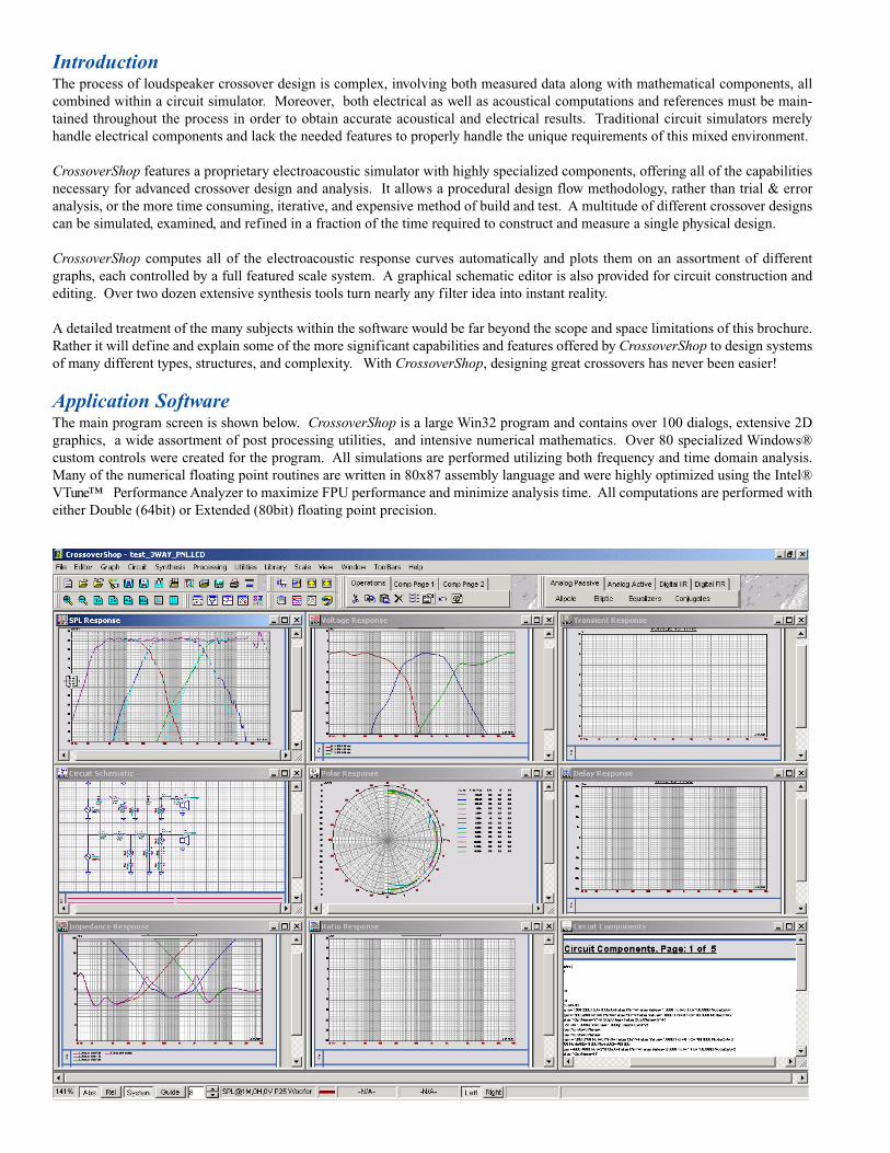
Application SoftwareThe main program screen is shown below. CrossoverShop is a large Win32 program and contains over 100 dialogs, extensive 2Dgraphics, a wide assortment of post processing utilities, and intensive numerical mathematics. Over 80 specialized Windows®custom controls were created for the program. All simulations are performed utilizing both frequency and time domain analysis.Many of the numerical floating point routines are written in 80x87 assembly language and were highly optimized using the Intel®VTune™ Performance Analyzer to maximize FPU performance and minimize analysis time. All computations are performed witheither Double (64bit) or Extended (80bit) floating point precision.
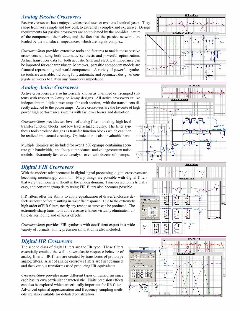
Digital FIR CrossoversWith the modern advancements in digital signal processing, digital crossovers arebecoming increasingly common. Many things are possible with digital filtersthat were traditionally difficult in the analog domain. Time correction is triviallyeasy, and constant group delay using FIR filters also becomes possible.
FIR filters offer the ability to apply equalization of driver/enclosure de-fects as never before resulting in razor flat response. Due to the extremelyhigh order of FIR filters, nearly any response curve can be produced. Theextremely sharp transitions at the crossover knees virtually eliminate mul-tiple driver lobing and off-axis effects.
CrossoverShop provides FIR synthesis with coefficient export in a widevariety of formats. Finite precision simulation is also included.
Digital IIR CrossoversThe second class of digital filters are the IIR type. These filtersessentially emulate the well known classic response behavior ofanalog filters. IIR filters are created by transforms of prototypeanalog filters. A set of analog crossover filters are first designed,and then various transforms used producing IIR equivalents.
CrossoverShop provides many different types of transforms sinceeach has its own particular characteristic. Finite precision effectscan also be explored which are critically important for IIR filters.Advanced optimal approximation and frequency sampling meth-ods are also available for detailed equalization.
Analog Active CrossoversActive crossovers are also historically known as bi-amped or tri-amped sys-tems with respect to 2-way or 3-way designs. All active crossovers utilizeindependent multiple power amps for each section, with the transducers di-rectly attached to the power amps. Active crossovers are the favorite of highpower high performance systems with far lower losses and distortion.
CrossoverShop provides two levels of analog filter modeling: high leveltransfer function blocks, and low level actual circuitry. The filter syn-thesis tools produce designs as transfer function blocks which can thenbe realized into actual circuitry. Optimization is also invaluable here.
Multiple libraries are included for over 1,500 opamps containing accu-rate gain bandwidth, input/output impedance, and voltage/current noisemodels. Extremely fast circuit analysis even with dozens of opamps.
Analog Passive CrossoversPassive crossovers have enjoyed widespread use for over one hundred years. Theyrange from very simple and low cost, to extremely complex and expensive. Designrequirements for passive crossovers are complicated by the non-ideal natureof the components themselves, and the fact that the passive networks areloaded by the transducer impedances, which are highly complex.
CrossoverShop provides extensive tools and features to tackle these passivecrossovers utilizing both automatic synthesis and powerful optimization.Actual transducer data for both acoustic SPL and electrical impedance canbe imported for each transducer. Moreover, parasitic component models arefeatured representing real world components. A variety of powerful synthe-sis tools are available, including fully automatic and optimized design of con-jugate networks to flatten any transducer impedance.

Advanced Specialized Circuit ComponentsThere are many different types of circuit components supported in the program. Manyof these components have unique capabilities and were specifically created to supportadvanced filter design and crossover analysis. Both analog and digital circuit analysisis provided including any combination of mixed designs.
■ ResistorThis component also includes parasitic models for parallel capacitance and series inductance. It also includes aexponential frequency dependent model to simulate losses in ferrite/iron core inductors.
■ CapacitorThis component also includes parasitic models for series resistance and inductance. It also includes a exponentialfrequency dependent model to simulate various types of dielectric behavior.
■ InductorThis component also includes parasitic models for parallel capacitance and series resistance. It also includes a expo-nential frequency dependent model to simulate losses in ferrite/iron core inductors.
■ FDNR (Frequency Dependent Negative Resistor)This component could be described as a capacitor squared. It is commonly used in the design of gyrators.
■ PotentiometerA powerful component to simulate pots, with automatic rotation and curve production. Libraries of tapers provided.
■ TransformerPrimary, secondary, mutual, leakage inductance and turns ratio.
■ Imported ImpedanceReal components can be measured and their impedance curves imported for use in the circuit simulations.
■ SwitchVarious pole arrangements. Model includes resistance and shunting capacitance.
■ TFB (Transfer Function Block)Very powerful component which can generate a wide variety of transfer functions, including imported curves.
■ GeneratorBasic source of signals in all circuits. Also includes noise generator and custom response modification.
■ SummerThis component enables signals to be added or subtracted. It has two or three inputs, each with selectable polarity.The inputs and output have finite impedance and are ground referenced. This component is useful for takingdifferential measurements and/or producing single ended outputs from balanced circuits.
■ SCN (Switched Capacitor Network)The SCN models the frequency domain sampling behavior of switched capacitor resistor structures.
■ IIR FilterThis component models the frequency domain behavior of a digital IIR filter.
■ FIR FilterThis component models the frequency domain behavior of a digital FIR filter.
■ BufferProvides three precision functions: invert the polarity of a signal, change the gain of a signal, or delay a signal.
■ TransducerUndoubtedly the most important component of the electroacoustic circuit simulator. This component defines both theelectrical and acoustical properties of the transducer, and also specifies the 3-D location of the transducer on theenclosure. Full support for dual-voice coil transducers is also provided.
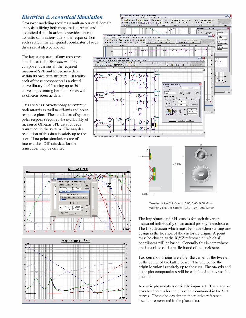
Electrical & Acoustical SimulationCrossover modeling requires simultaneous dual domainanalysis utilizing both measured electrical andacoustical data. In order to provide accurateacoustic summations due to the response fromeach section, the 3D spatial coordinates of eachdriver must also be known.
The key component of any crossoversimulation is the Transducer. Thiscomponent carries all the requiredmeasured SPL and Impedance datawithin its own data structure. In realityeach of these components is a virtualcurve library itself storing up to 50curves representing both on-axis as wellas off-axis acoustic data.
This enables CrossoverShop to computeboth on-axis as well as off-axis and polarresponse plots. The simulation of systempolar response requires the availability ofmeasured Off-axis SPL data for eachtransducer in the system. The angularresolution of this data is solely up to theuser. If no polar simulations are ofinterest, then Off-axis data for thetransducer may be omitted.
Woofer Voice Coil Coord: 0.00, -0.25, -0.07 Meter
Tweeter Voice Coil Coord: 0.00, 0.00, 0.00 Meter
- 0.25M
- 0.07M
+y
+z
+y
+x
The Impedance and SPL curves for each driver aremeasured individually on an actual prototype enclosure.The first decision which must be made when starting anydesign is the location of the enclosure origin. A pointmust be chosen as the X,Y,Z reference on which allcoordinates will be based. Generally this is somewhereon the surface of the baffle board of the enclosure.
Two common origins are either the center of the tweeteror the center of the baffle board. The choice for theorigin location is entirely up to the user. The on-axis andpolar plot computations will be calculated relative to thisposition.
Acoustic phase data is critically important. There are twopossible choices for the phase data contained in the SPLcurves. These choices denote the relative referencelocation represented in the phase data.

Crossover WizardIf you ever wanted a method of designing a crossover simply byclicking a button, the crossover Wizard was created for you. Thisutility is a sophisticated collection of highly automated routineswhich can automatically design complex crossovers of manydifferent types. The user is still responsible for collecting andproviding the necessary information and measurements.
The Wizard is a series of dialogs which provide an easy and quickmeans of designing a crossover. Prior to starting the crossoverWizard you must import all of the Impedance and SPL curvesnecessary for your design. The Wizard will ask you a short series ofsimple questions and then will automatically layout the completecrossover circuit for you. It will also optimize the crossover design.
Using the Wizard is one of the easiest ways to get an initialcrossover setup. However once the Wizard has completed its tasks,you can certainly edit, change, or modify the design as you wouldany other design. The Wizard is simply another means of starting acrossover design.
In some cases the results from the Wizard may be very close to whatyou desire. The Wizard was constructed to perform commoncrossover designs. It is not meant to provide every possible designpermutation and special exception. For those situations you willneed to modify the final Wizard design, or construct your owndesign manually as normal.
■ Step-1The first step is to choose what type of crossover you desire, anddefine how many sections there will be. These choices will controlwhat parameters and options will be needed in the following steps.
■ Step-2In this step the order and frequency points of the crossoverobjectives are defined. These are the alignments to which theresponse will be optimized. There may also be some optionalcrossover items available, depending on the type of crossoverdesign. Only one of the four tabs will be available, and thisselection will be made for you based on the type of design.
■ Step-3Here you will define the location of the data curves for each of thecrossover sections, the actual filter orders, and also the coordinatesof each transducer. If a particular section is not used, it will begrayed out. Choose the proper SPL and Impedance curve entrieswhere you placed the transducer data. The Order selection definesthe actual filter order to use for each crossover section in the design.This is often not the same as the optimization objective order for thealignment. The filter order is often less than the objective order, dueto the non-flat response of the transducer itself.
■ Step-4When optimizing the crossover sections, the frequency region wherethe optimization will be performed must be specified. This is shownas the Red line across a portion of the transducer's response. Youcan change the limits of the crossover optimization frequency rangeby simply clicking the mouse near the ends of the Red line. Someregions of the transducer's response may not be controllable by thecrossover and should therefore not be included.
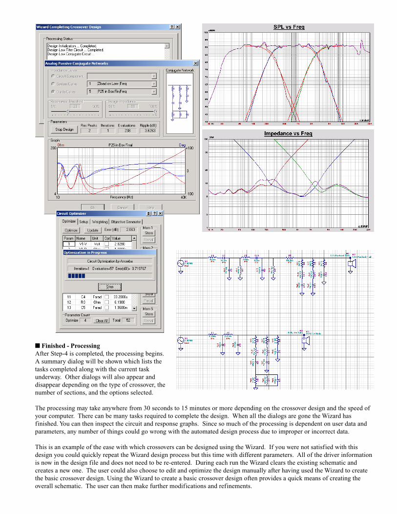
■ Finished - ProcessingAfter Step-4 is completed, the processing begins.A summary dialog will be shown which lists thetasks completed along with the current taskunderway. Other dialogs will also appear anddisappear depending on the type of crossover, thenumber of sections, and the options selected.
The processing may take anywhere from 30 seconds to 15 minutes or more depending on the crossover design and the speed ofyour computer. There can be many tasks required to complete the design. When all the dialogs are gone the Wizard hasfinished. You can then inspect the circuit and response graphs. Since so much of the processing is dependent on user data andparameters, any number of things could go wrong with the automated design process due to improper or incorrect data.
This is an example of the ease with which crossovers can be designed using the Wizard. If you were not satisfied with thisdesign you could quickly repeat the Wizard design process but this time with different parameters. All of the driver informationis now in the design file and does not need to be re-entered. During each run the Wizard clears the existing schematic andcreates a new one. The user could also choose to edit and optimize the design manually after having used the Wizard to createthe basic crossover design. Using the Wizard to create a basic crossover design often provides a quick means of creating theoverall schematic. The user can then make further modifications and refinements.
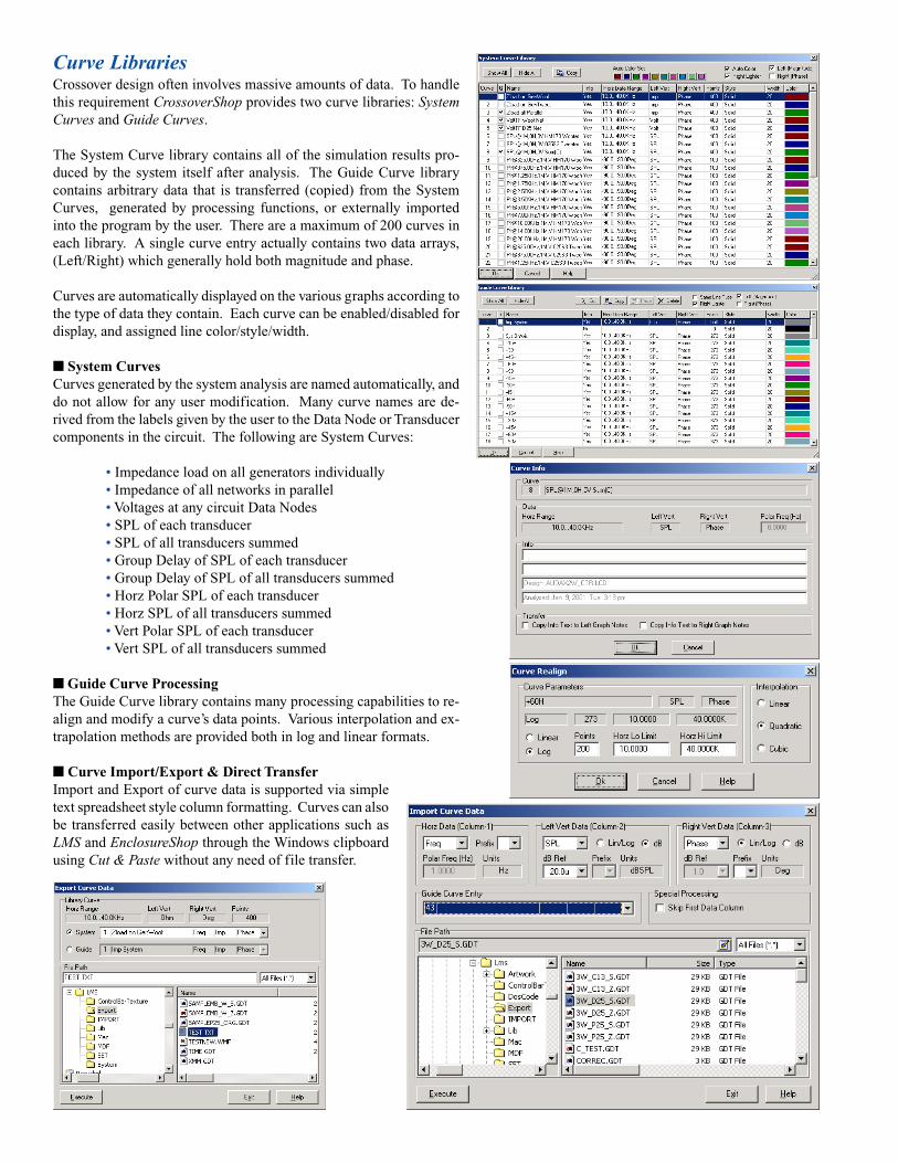
Curve LibrariesCrossover design often involves massive amounts of data. To handlethis requirement CrossoverShop provides two curve libraries: SystemCurves and Guide Curves.
The System Curve library contains all of the simulation results pro-duced by the system itself after analysis. The Guide Curve librarycontains arbitrary data that is transferred (copied) from the SystemCurves, generated by processing functions, or externally importedinto the program by the user. There are a maximum of 200 curves ineach library. A single curve entry actually contains two data arrays,(Left/Right) which generally hold both magnitude and phase.
Curves are automatically displayed on the various graphs according tothe type of data they contain. Each curve can be enabled/disabled fordisplay, and assigned line color/style/width.
■ System CurvesCurves generated by the system analysis are named automatically, anddo not allow for any user modification. Many curve names are de-rived from the labels given by the user to the Data Node or Transducercomponents in the circuit. The following are System Curves:
• Impedance load on all generators individually• Impedance of all networks in parallel• Voltages at any circuit Data Nodes• SPL of each transducer• SPL of all transducers summed• Group Delay of SPL of each transducer• Group Delay of SPL of all transducers summed• Horz Polar SPL of each transducer• Horz SPL of all transducers summed• Vert Polar SPL of each transducer• Vert SPL of all transducers summed
■ Guide Curve ProcessingThe Guide Curve library contains many processing capabilities to re-align and modify a curve’s data points. Various interpolation and ex-trapolation methods are provided both in log and linear formats.
■ Curve Import/Export & Direct TransferImport and Export of curve data is supported via simpletext spreadsheet style column formatting. Curves can alsobe transferred easily between other applications such asLMS and EnclosureShop through the Windows clipboardusing Cut & Paste without any need of file transfer.
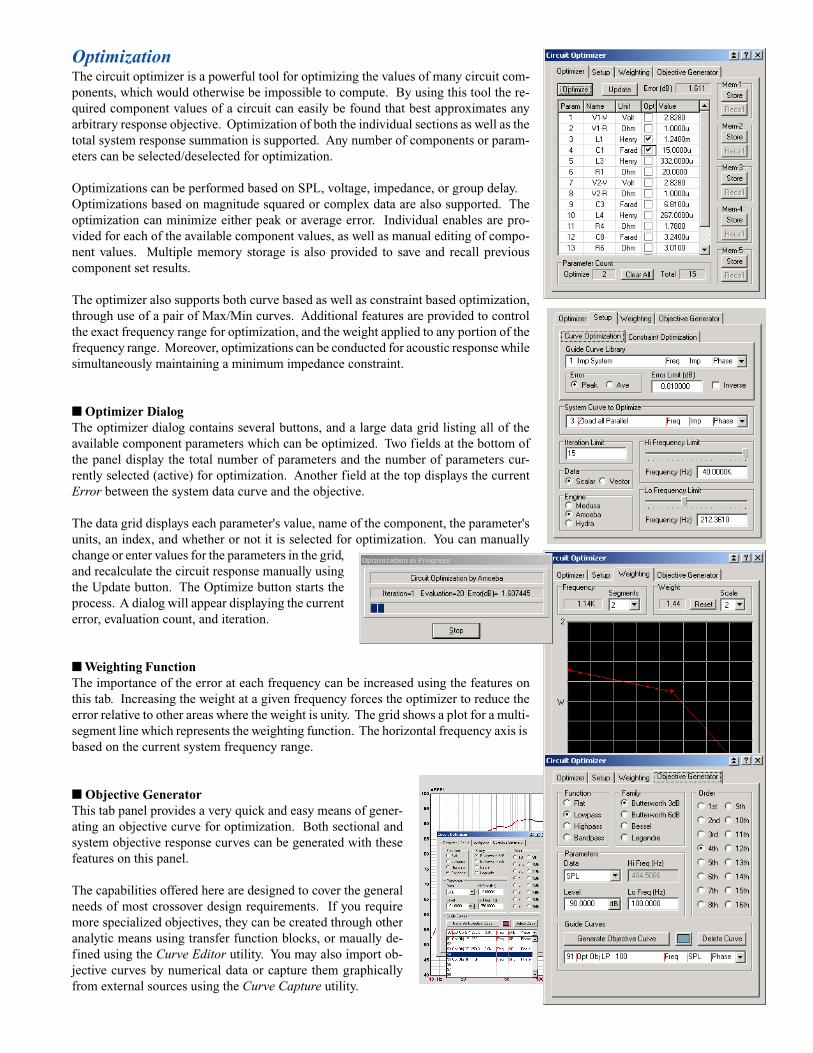
OptimizationThe circuit optimizer is a powerful tool for optimizing the values of many circuit com-ponents, which would otherwise be impossible to compute. By using this tool the re-quired component values of a circuit can easily be found that best approximates anyarbitrary response objective. Optimization of both the individual sections as well as thetotal system response summation is supported. Any number of components or param-eters can be selected/deselected for optimization.
Optimizations can be performed based on SPL, voltage, impedance, or group delay.Optimizations based on magnitude squared or complex data are also supported. Theoptimization can minimize either peak or average error. Individual enables are pro-vided for each of the available component values, as well as manual editing of compo-nent values. Multiple memory storage is also provided to save and recall previouscomponent set results.
The optimizer also supports both curve based as well as constraint based optimization,through use of a pair of Max/Min curves. Additional features are provided to controlthe exact frequency range for optimization, and the weight applied to any portion of thefrequency range. Moreover, optimizations can be conducted for acoustic response whilesimultaneously maintaining a minimum impedance constraint.
■ Optimizer DialogThe optimizer dialog contains several buttons, and a large data grid listing all of theavailable component parameters which can be optimized. Two fields at the bottom ofthe panel display the total number of parameters and the number of parameters cur-rently selected (active) for optimization. Another field at the top displays the currentError between the system data curve and the objective.
The data grid displays each parameter's value, name of the component, the parameter'sunits, an index, and whether or not it is selected for optimization. You can manuallychange or enter values for the parameters in the grid,and recalculate the circuit response manually usingthe Update button. The Optimize button starts theprocess. A dialog will appear displaying the currenterror, evaluation count, and iteration.
■ Weighting FunctionThe importance of the error at each frequency can be increased using the features onthis tab. Increasing the weight at a given frequency forces the optimizer to reduce theerror relative to other areas where the weight is unity. The grid shows a plot for a multi-segment line which represents the weighting function. The horizontal frequency axis isbased on the current system frequency range.
■ Objective GeneratorThis tab panel provides a very quick and easy means of gener-ating an objective curve for optimization. Both sectional andsystem objective response curves can be generated with thesefeatures on this panel.
The capabilities offered here are designed to cover the generalneeds of most crossover design requirements. If you requiremore specialized objectives, they can be created through otheranalytic means using transfer function blocks, or maually de-fined using the Curve Editor utility. You may also import ob-jective curves by numerical data or capture them graphicallyfrom external sources using the Curve Capture utility.
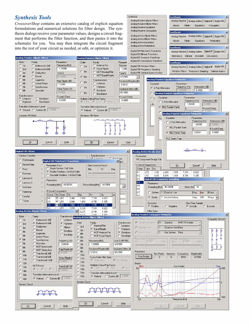
Synthesis ToolsCrossoverShop contains an extensive catalog of explicit equationformulations and numerical solutions for filter design. The syn-thesis dialogs receive your parameter values, designs a circuit frag-ment that performs the filter function, and then pastes it into theschematic for you. You may then integrate the circuit fragmentinto the rest of your circuit as needed, or edit, or optimize it.
Simulation
Measurement
Measurement
Simulation
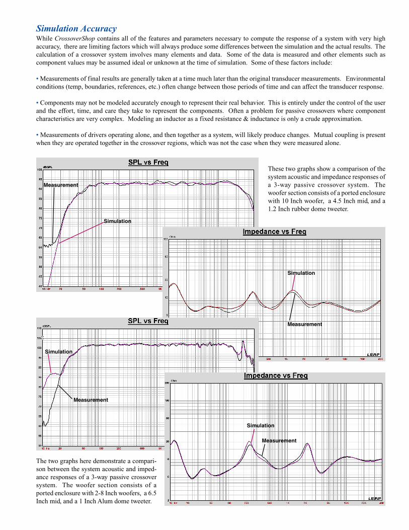
Simulation AccuracyWhile CrossoverShop contains all of the features and parameters necessary to compute the response of a system with very highaccuracy, there are limiting factors which will always produce some differences between the simulation and the actual results. Thecalculation of a crossover system involves many elements and data. Some of the data is measured and other elements such ascomponent values may be assumed ideal or unknown at the time of simulation. Some of these factors include:
• Measurements of final results are generally taken at a time much later than the original transducer measurements. Environmentalconditions (temp, boundaries, references, etc.) often change between those periods of time and can affect the transducer response.
• Components may not be modeled accurately enough to represent their real behavior. This is entirely under the control of the userand the effort, time, and care they take to represent the components. Often a problem for passive crossovers where componentcharacteristics are very complex. Modeling an inductor as a fixed resistance & inductance is only a crude approximation.
• Measurements of drivers operating alone, and then together as a system, will likely produce changes. Mutual coupling is presentwhen they are operated together in the crossover regions, which was not the case when they were measured alone.
Measurement
Simulation
Measurement
Simulation
The two graphs here demonstrate a compari-son between the system acoustic and imped-ance responses of a 3-way passive crossoversystem. The woofer section consists of aported enclosure with 2-8 Inch woofers, a 6.5Inch mid, and a 1 Inch Alum dome tweeter.
These two graphs show a comparison of thesystem acoustic and impedance responses ofa 3-way passive crossover system. Thewoofer section consists of a ported enclosurewith 10 Inch woofer, a 4.5 Inch mid, and a1.2 Inch rubber dome tweeter.

LINEARX SYSTEMS INC9500 SW Tualatin-Sherwood RdTualatin, OR 97062-8586 USA
Tel: 503-612-9565 Fax: 503-612-9344www.linearx.com [email protected]
Contact factory or visit our web site for alist of International Dealers.
All specifications subject to change without notice.© 2004-2007 All Rights Reserved.Printed in the U.S.A.MAR-22-2007
CrossoverShop Highlights• Mixed Electroacoustic Circuit Simulator
• Analog Passive Network Crossover Design
• Analog Active Filter Crossover Design
• Digital IIR Filter Crossover Design
• Digital FIR Filter Crossover Design
• Mixed Analog & Digital Crossover Design
• Synthesis of Passive Allpole/Elliptic/Conjugates
• Synthesis of Active Allpole/Elliptic/EQ/Circuits
• Synthesis of IIR Matched-Z/Bilinear/Conv/Inv
• Synthesis of FIR Window/FreqSamp/Optimal
• Advanced Global Optimization Engines
• Curve based Peak/Average Optimization
• Constraint based Max/Min Optimization
• Frequency Range Restricted Optimization
• Weighting Function Modified Optimization
• Memory Store/Recall of Optimization Results
• Optimization of SPL, Impedance, GroupDelay
• Automatic Optimizer Objective Generators
• Graphical Schematic Entry/Editing
• Automated Crossover Design Wizard
• Polar Simulation with Measured Off-Axis Data
• 22 Advanced/Specialized Circuit Components
• Opamp Model Library, 1000 predefined
• Potentiometer Taper Library, 250 predefined
• Thermal, MonteCarlo, Sensitivity Analysis
• Powerful System & Guide Curve Libraries
• Post Processing Utilities & Math Functions
• Accurate Dual Voice Coil Simulations
• Import, Export, Cut & Paste Curve Data
• Graphics Export Raster & Vector Formats
• Curve Capture/Converter from Raster Image
• Curve Editor, Node Smoothing, Add, Delete
• Air Core Inductor Designer
• Comprehensive 2-Volume Manual Set
System RequirementsCrossoverShop is a highly intensive numerical application. Theprogram contains literally hundreds of numerical mathematicsalgorithms, some of which are extremely large and place very highdemands on the CPU's floating point performance.
CrossoverShop will use all of the speed your processor has to offer,and can probably want more. Depending on the speed and type ofCPU in your system, and the complexity of your design, some ofthe circuit analysis can require many minutes to run.
CrossoverShop also uses extensive graphics. For best results a1024 x 768 video resolution is suggested with at least 64K (16-bit)color depth.
Minimum System Requirements:• Mouse and Keyboard• USB port for License Key• Windows® 95, 98, SE, ME, NT4, 2000, XP• 250MB free Hard Drive space• 64MB RAM Memory• Pentium® II / 350 or equivalent• Video 800 x 600 Resolution / 256 Colors• TrueType® or Adobe® Fonts
Recommended System Requirements:• Windows® 2000 or Windows® XP• 300MB free Hard Drive space• 256MB RAM Memory or more• Pentium® III / 800 or equivalent• Video 1024 x 768 Res / 64K or 16M Colors• Adobe® Fonts with Adobe Type Manager®
Note: Due to the limitations of Win9X, not all of the program'sfeatures and/or capabilities will be available in those operatingsystems.