
Lotus Service Notes Section FAvsic.lotuscars.com/system/files/documents/sn_fa_automatic... · Page...
64
Page 1 Lotus Service Notes Section FA AUTOMATIC TRANSMISSION - IPS (INTELLIGENT PRECISION SHIFT) SECTION FA Sub-Section Page Introduction FA.1 3 Gearchange Mechanism FA.2 5 PRND Selection FA.3 8 Transmission Fluid Cooling FA.4 10 Transmission Fluid Level Checking, Adjustment & Draining FA.5 11 Ignition Key Interlock and Battery Disconnection FA.6 15 Vehicle Recovery and Towing FA.7 16 Transmission Diagnostic Codes FA.8 27 Driveshafts F.A.9 60 Transmission Removal FA.10 64 Updated 7 th Februar y 2014 1
Transcript of Lotus Service Notes Section FAvsic.lotuscars.com/system/files/documents/sn_fa_automatic... · Page...
Page 1
Lotus Service Notes Section FA
AutomAtic trANSmiSSioN - iPS (iNteLLigeNt PreciSioN ShiFt)
SECTION FA
Sub-Section Page
Introduction FA.1 3
Gearchange Mechanism FA.2 5
PRND Selection FA.3 8 Transmission Fluid Cooling FA.4 10
Transmission Fluid Level Checking, Adjustment & Draining FA.5 11 Ignition Key Interlock and Battery Disconnection FA.6 15
Vehicle Recovery and Towing FA.7 16
Transmission Diagnostic Codes FA.8 27
Driveshafts F.A.9 60
Transmission Removal FA.10 64
Updated 7th February 2014
1

Page 2
Lotus Service Notes Section FA
No.1 Clutch
No.2 ClutchNo.1 BrakeNo.2 Brake
No.3 BrakeNo.1 One-way Clutch
Counter Drive Gear
U/D PlanetaryGear Unit
DifferentialDrive Pinion
Input Shaft
CounterDriven Gear
Ravigneaux PlanetaryGear Unit
Crownwheel
Differential
f150
geNerAL LAYout
Page 3
Lotus Service Notes Section FA
FA.1 - GENERAL DESCRIPTION
U660E automatic transaxle is used on the 2GR-FE engine models. This automatic transaxle is a compact, lightweight and high-capacity 6-speed Super ECT (Electronically Controlled Transaxle).
The unit is fully described on CD Lotus part number T000T1526F (Toyota ref. SC0264EA).
Insert the disc into a personal computer, and it will automatically open up to the GSIC – Global Service Information Center page. Select:
- New Car Features Supplement.- NM0260E.- Chassis.- U660E Automatic Transaxle.
Note the U660E transmission is used by Toyota in combination with the 2GR-FE V6 engine, unlike the manual EA60 transmission it is not necessary to use an adaptor plate between the engine and transmission, or modify the bell housing to mount the starter motor.
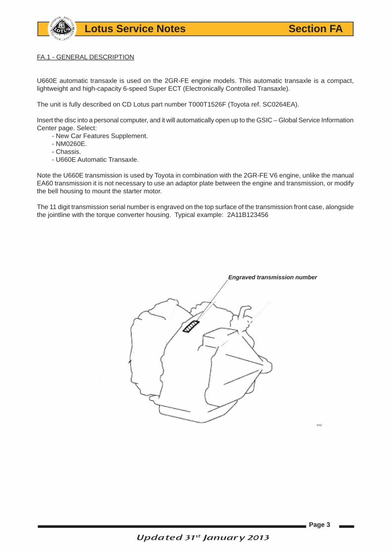
The 11 digit transmission serial number is engraved on the top surface of the transmission front case, alongside the jointline with the torque converter housing. Typical example: 2A11B123456
Engraved transmission number
f152
Updated 31st January 2013

Page 4
Lotus Service Notes Section FA
Operating Principle
The Evora IPS utilises the Toyota 6 speed U660E conventional fluid filled automatic transmission and torque converter assembly which is bolted directly onto the 2GR-FE naturally aspirated engine unit.
PRND (Park – Reverse – Neutral – Drive) selections are electronically activated by push button control panel located in the centre console.
A PRND request activates a shift actuator module mounted to the top of the transmission, moving a shift rod which, in turn, alters the position of the transmissions shift lever to engage gear.
Gear changes are controlled by the TCU (Transmission Control Unit) which is situated directly above the en-gine managements ECM (Electronic Control Module) located behind the access cover in the LH rear quarter trim panel. IPS System Modes:The Lotus IPS transmission system allows the driver to switch between conventional 6 speed automatic drive to manual paddle shift mode with the option of ‘Sport’ mode producing quicker and more pronounced gear shifts as well as optimising shift points for performance.
IPS Characteristics:Automatic transmission: Using the PRND selector within the centre console, gear shifts are biased towards refinement, and shifting points are automatically selected to optimise refinement and fuel economy.
Manual sequential gear selection: Forward gears can be manually selected using the paddle shifters provided within the steering wheel.
SHIFT
ACTUATOR
GEARBOX
CONNECTOR
TCU
ECU
PADDLE SHIFT
COMMANDS
SWITCH PANEL
ASSEMBLY
PADDLE SHIFT
PRND
COMMANDS
SPORT MODE
COMMANDS
f153

Page 5
Lotus Service Notes Section FA
FA.2 - GEARCHANGE
PrND displayA PRND display is located at the top centre of the instrument panel. The PRND selection requested by the driver will be shown as well as the forward gear selected (1-6) by the IPS system.
Automatic transmission using PrND gear SelectorWith ignition switch turned to position II, initial gear se-lections (Park Reverse Neutral or Drive) are accessed from the buttons on the PRND control panel located in the centre console,
Note: The engine can only be started if either P or N is selected and the footbrake is depressed.
The engine should only be turned off once the vehicle is stationary and P – Park or N – Neutral has been se-lected. Not doing so may cause serious damage to the transmission.
With the engine stopped (ignition switch in position I) P is automatically selected.
To remain in Neutral with the engine stopped, select N before turning the ignition switch to position I.
Note: The key cannot be removed from the ignition switch until P has been selected.
PrND Button FunctionsP – Park: Select only when the vehicle is stationary to permanently lock the transmission.Note: Park will be selected automatically when the ignition is switched off and the vehicle speed is below 1.2 mph (2km/h).
Never select the Park (P) position whilst the vehicle is in motion. Doing so may cause serious dam-age to the transmission.
R – Reverse: Select only when vehicle is stationary to engage reverse gear. To avoid unexpected or sudden vehicle movement do not rev the engine or allow it to run above normal idle speed while selecting D or R, or while the vehicle is stationary with any gear selected.N – Neutral: Select only when the vehicle is stationary to temporarily disengage drive to the rear wheels. It is recommended that the parking brake is applied if neutral is selected.D – Drive: Select only when the vehicle is stationary to engage forward gears. IPS gear changing shifting points for all six forward gears are controlled and determined by the accelerator pedal position and vehicle speed as well as other information received by the TCU (Transmission Control Unit).
Appropriate gear Selection using PrND PanelP – Park: Press button P to select*, vehicle road speed must be below 1.2 mph (2km/h).R – Reverse: Press button R to select*, vehicle road speed must be below 1.2 mph (2km/h).
Never select the Reverse (R) position whilst the vehicle is in forward motion. Doing so may cause serious damage to the transmission.
N – Neutral: Press button N to select*, the footbrake must be depressed if selecting from P – Park. If selecting from R – Reverse: vehicle road speed must be below 1.2 mph (2km/h).
D – Drive: press button D to select* from:
P - Park: the footbrake must be depressed.R – Reverse: vehicle road speed must be below 1.2 mph (2km/h)
NOTICE
1
NOTICE
R N D
P
Reverse button
Neutralbutton Drive button Park button
PRND SELECTOR CONSOLE
Page 6
Lotus Service Notes Section FA
N – Neutral: footbrake must be depressed if vehicle road speed is below 1.2 mph (2km/h). If vehicle road speed is over 1.2 mph (2km/h) the footbrake does not have to be depressed.
*To avoid potential damage to the engine and transmission a driver PRND selection, under certain conditions, can only be achieved if the gear selection requested is ‘appropriate’ to the vehicles current road speed and, if neccessary with the footbrake depressed.
If an appropriate PRND request is selected: the button pressed on the selector console will illuminate bright red. The PRND indicator display situated in the instrument panel will illuminate accordingly to show the gear selected. The transmission will then engage gear.
If an inappropriate PRND request is selected: the button pressed in the selector console will not illuminate. The current gear selection will remain bright red on the PRND panel and the transmission will not engage the gear requested.
Kick-downWhen in D – Drive with the accelerator pedal depressed fully, the transmission will downshift to the lowest ap-propriate gear. Once the accelerator pedal is returned to a normal driving position, the transmission will up-shift to the highest appropriate gear.
Note: Kick-down operation will vary according to road speed, current gear in use and accelerator movement.
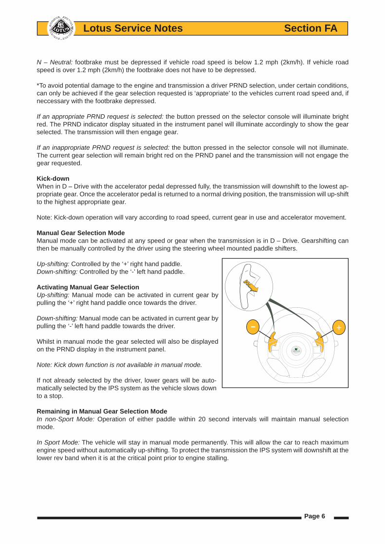
manual gear Selection modeManual mode can be activated at any speed or gear when the transmission is in D – Drive. Gearshifting can then be manually controlled by the driver using the steering wheel mounted paddle shifters.
Up-shifting: Controlled by the ‘+’ right hand paddle.Down-shifting: Controlled by the ‘-’ left hand paddle.
Activating manual gear SelectionUp-shifting: Manual mode can be activated in current gear by pulling the ‘+’ right hand paddle once towards the driver.
Down-shifting: Manual mode can be activated in current gear by pulling the ‘-’ left hand paddle towards the driver.
Whilst in manual mode the gear selected will also be displayed on the PRND display in the instrument panel.
Note: Kick down function is not available in manual mode.
If not already selected by the driver, lower gears will be auto-matically selected by the IPS system as the vehicle slows down to a stop.
remaining in manual gear Selection modeIn non-Sport Mode: Operation of either paddle within 20 second intervals will maintain manual selection mode.
In Sport Mode: The vehicle will stay in manual mode permanently. This will allow the car to reach maximum engine speed without automatically up-shifting. To protect the transmission the IPS system will downshift at the lower rev band when it is at the critical point prior to engine stalling.
+−
Page 7
Lotus Service Notes Section FA
returning to Automatic transmission
In Sport Mode:• Select D – Drive button on the PRND console. or;• Pull ‘+’ up-shift paddle for 2 seconds. or:. If Sport Mode is deactivated.
Non Sport Mode:• Select D – Drive button on the PRND console, or;• Pull ‘+’ up-shift paddle for 2 seconds, or;• Do not make a gear selection with either paddle shifter for 10 seconds or more.
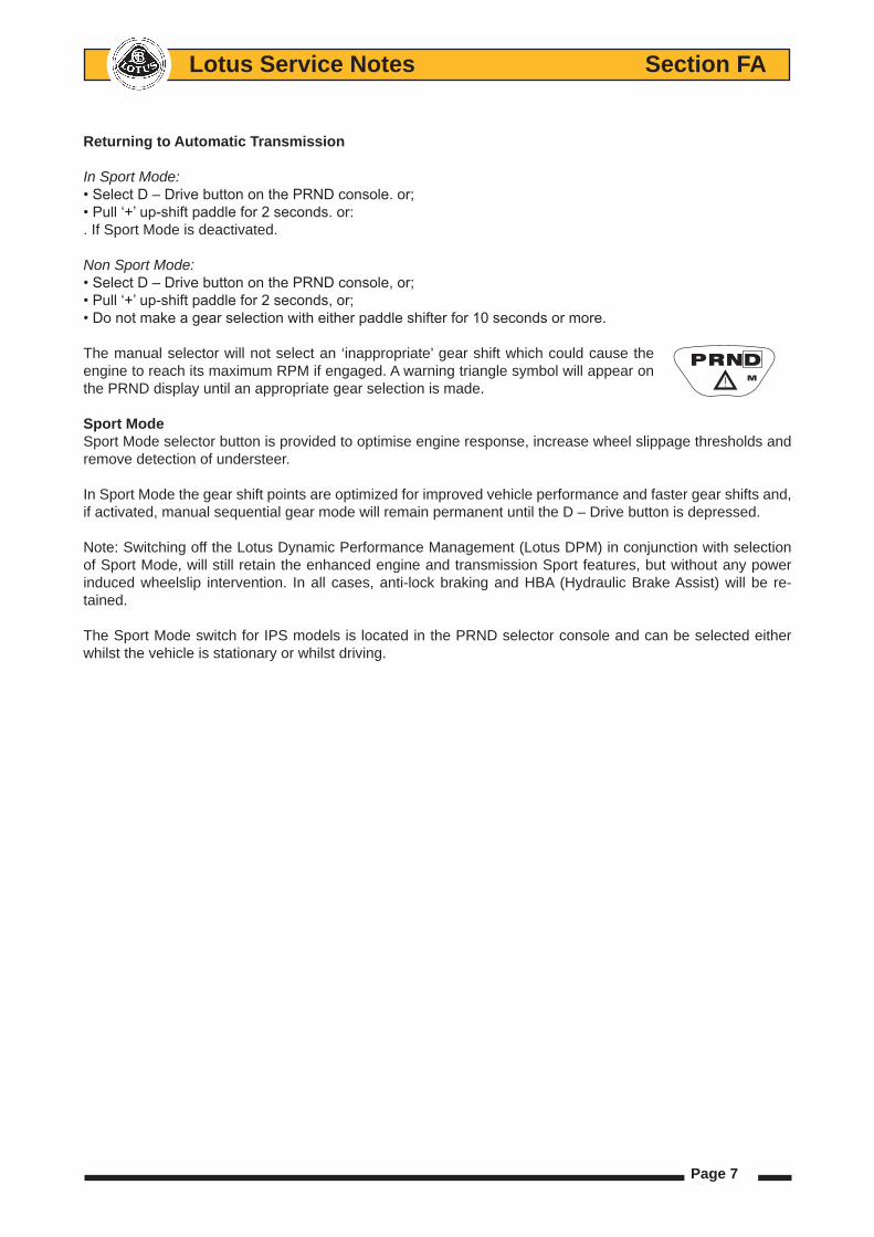
The manual selector will not select an ‘inappropriate’ gear shift which could cause the engine to reach its maximum RPM if engaged. A warning triangle symbol will appear on the PRND display until an appropriate gear selection is made.
Sport modeSport Mode selector button is provided to optimise engine response, increase wheel slippage thresholds and remove detection of understeer.
In Sport Mode the gear shift points are optimized for improved vehicle performance and faster gear shifts and, if activated, manual sequential gear mode will remain permanent until the D – Drive button is depressed.
Note: Switching off the Lotus Dynamic Performance Management (Lotus DPM) in conjunction with selection of Sport Mode, will still retain the enhanced engine and transmission Sport features, but without any power induced wheelslip intervention. In all cases, anti-lock braking and HBA (Hydraulic Brake Assist) will be re-tained.
The Sport Mode switch for IPS models is located in the PRND selector console and can be selected either whilst the vehicle is stationary or whilst driving.
� M

Page 8
Lotus Service Notes Section FA
FA.3 - PRND SELECTION
The transmissions shift lever is operated by a ‘Shift by wire’ actuator. A PRND command from the drivers switch panel via the TCU activates the shift actuator mounted to the top of the transmission assembly.
A shift rod connects the actuator’s lever arm to the transmission’s modified selector lever.
The motor within the shift actuator rotates an attached lever arm to one of four set positions in relation to the command sent from the switch panel, which in turn rotates the selector lever to the correct PRND position.
Removal of the shift actuator assembly
Using PRND switch panel, set transmission 1. to N – neutral.
The actuator lever arm should now be at 2. an 11 o’clock and positioned slightly to the right of the moulded rib on the pinion housing. (see illustration).
If neutral has been successfully selected 3. then the blue setting marks on the neutral switch and its housing will line up (see illustration).
Disconnect the shift rod from the actuator 4. lever arm by pulling it off from its ball mounting.
Disconnect the wiring harness multi-plug 5. connector from the shift actuator.
f155
Shift actuator
Shift rod
Selector lever
Actuator to transmission bracket
Park/neutral switch
Actuatorlever arm
Shift 4. lever rod
f155
Actuator lever arm 2. in neutral postion
Neutral setting 3. marks
Pinion housing moulding

Page 9
Lotus Service Notes Section FA
Release the 3 M8 x 20 screws securing the actuator to it 6. bracket and remove
Refitment of the shift actuator assembly or shift rod
Ensure that the actuators lever arm is positioned slightly to 1. the right of the pinion housing moulding (see illustration on above page).
Refit the shift actuator assembly to its bracket using its 3 M8 2. x 20 screws (torque to 24Nm).
Reconnect the wiring harness multi-plug to the actuator, operate the PRND switch panel and check that 3. lever arm rotates when activated but returns to its neutral position with neutral selected.
Ensure that the blue setting marks on the neutral switch and its housing are aligned, move the selector 4. lever to the required position if necessary (see illustration on above page).
Pull the shift rods locking tab upwards, this will allow the select lever joint to move independently of the 5. rod so its length can be adjusted.
Push the lever arms rod joint onto the ball of the shift lever and push the locking tab back into the selector 6. joint, this will set the rod to the correct length.
Operate the PRND switch panel to check the operation of the actuator, shift rod and selector lever. 7.
Shift actuator retainingscrews
f156
Pull the locking tab upwards to release selector joint from the shift rod
Press the locking tab inwards to lock selector joint in position

Page 10
Lotus Service Notes Section FA
FA.4 - TRANSMISSION FLUID COOLING
Under normal driving conditions the temperature of the transmission fluid within gearbox can reach 100° Centi-
grade. Fluid temperate can increase dramatically with an increase in gearbox load, engine speed and ambient
temperature.
Transmission fluid operating temperature range
Temperature Condition
40°C – 100°C: Normal transmission fluid operating temperature range.
72°C: Sandwich plate assembly opens diverting fluid to front mounted oil coolers.
140°C: Maximum safe transmission fluid operating temperature.
If the maximum safe fluid temperature is maintained for over 10 seconds, then vehicle power
will be reduced and the TCU warning light will be illuminated.
135°C : When the transmission fluid temperature decreases the full power is restored and the TCU
(Transmission Control Unit) warning light is extinguished
External air to oil coolers are used to prevent the transmission fluid breaking down under extreme temperature
as well as ensuring that mechanical and electrical components within the gearbox are not subjected to extreme
heat transmitted by the fluid.
‘11MY IPS Models
The same front mounted air/oil coolers used on the ‘11MY Evora ‘S’ for engine oil cooling are used to cool the
transmission fluid.
40° 72° 100° 135°
140°
Transmission Fluid Cooler Layout LH Rear sandwich
plate to sill feed
hose
Sandwich
plate
RH Rear sill pipe
to sandwich plate
return hose
LH Front
cooler feed hose
RH Front
cooler return
hose
Transfer
hose
LH Cooler
sill feed pipe
RH Cooler sill
return pipe
LH Cooler air
duct
Transmission to
sandwich plate
feed & return hosesf183
Updated 7th February 2014
Page 11
Lotus Service Notes Section FA
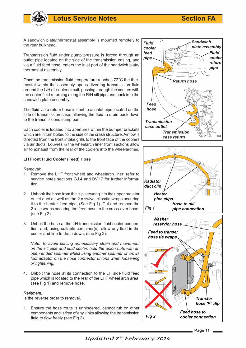
A sandwich plate/thermostat assembly is mounted remotely to
the rear bulkhead.
Transmission fluid under pump pressure is forced through an
outlet pipe located on the side of the transmission casing, and
via a fluid feed hose, enters the inlet port of the sandwich plate/
thermostat assembly.
Once the transmission fluid temperature reaches 72°C the ther-
mostat within the assembly opens diverting transmission fluid
around the L/H oil cooler circuit, passing through the coolers with
the cooler fluid returning along the R/H sill pipe and back into the
sandwich plate assembly.
The fluid via a return hose is sent to an inlet pipe located on the
side of transmission case, allowing the fluid to drain back down
to the transmissions sump pan.
Each cooler is located into apertures within the bumper brackets
which are in turn bolted to the side of the crash structure. Airflow is
directed from the front intake grills to the front face of the coolers
via air ducts. Louvres in the wheelarch liner front sections allow
air to exhaust from the rear of the coolers into the wheelarches.
LH Front Fluid Cooler (Feed) Hose
Removal:
Remove the LHF front wheel and wheelarch liner; refer to 1.
service notes sections GJ.4 and BV.17 for further informa-
tion.
Unhook the hose from the clip securing it to the upper radiator 2.
outlet duct as well as the 2 x swivel clips/tie wraps securing
it to the heater feed pipe, (See Fig 1). Cut and remove the
2 x tie wraps securing the feed hose to the cross-over hose,
(see Fig 2).
Unbolt the hose at the LH transmission fluid cooler connec-3.
tion, and, using suitable container(s), allow any fluid in the
cooler and line to drain down, (see Fig 2).
Note: To avoid placing unnecessary strain and movement
on the sill pipe and fluid cooler, hold the union nuts with an
open ended spanner whilst using another spanner or crows
foot adaptor on the hose connector unions when loosening
or tightening.
Unbolt the hose at its connection to the LH side fluid feed 4.
pipe which is located to the rear of the LHF wheel arch area,
(see Fig 1) and remove hose.
Refitment:
Is the reverse order to removal.
Ensure the hose route is unhindered, cannot rub on other 1.
components and is free of any kinks allowing the transmission
fluid to flow freely (see Fig 2).
Radiator
duct clip
Heater
pipe clips
Hose to sill
pipe connectionFig 1
Feed hose to
cooler connection
Transfer
hose 'P' clip
Sandwich
plate assembly
Fluid
cooler
return
pipe
f154
Feed
hose
Return hose
Fluid
cooler
feed
pipe
Transmission
case outlet
Transmission
case return
Fig 2
Feed to transer
hose tie wraps
Washer
reservior hose
Updated 7th February 2014

Page 12
Lotus Service Notes Section FA
Note: The feed hose should be routed so that is postioned in between the washer reservoir hose and crash
structure and to the left (outwards) of the transfer hose at the area where it passes near the transfer hose
'P' clip (see Fig 2).
Position the hose connection at the sill pipe so that it can follow the heater feed pipe routing without any
strain being placed on the hose once it is secured with new cable ties to the heater pipe. (See Fig 1).
Tighten the hose at the transmission cooler and sill pipe connections to 40Nm, a 30mm crowsfoot adaptor 2.
is required to carry out this operation. (Also see 'Note' in removal step 3 for tightening instructions).
If necessary fit new tie wraps to the swivel clips and re-check the hose routing.3.
Ensure the transmission fluid is topped up to allow for the fluid loss encountered during hose removal; refer 4.
to sub-section FA.5 for further information.
Connect Lotus TechCentre to the vehicle and run the engine and allow the temperature within transmission 5.
to rise to 72°C so that the transmission fluid level within the gearbox can be checked and adjusted and the
cooler circuit can be checked for leaks; refer to sub-section FA.5 for further information.
Refit the vehicle ancillary components previously removed once the correct transmission fluid level has 6.
been achieved.
Fluid Cooler Transfer Hose
Removal:
Remove both front wheels and wheelarch liners; refer to service 1.
notes section BV.17 for further information.
Remove front undershield; refer to service notes section A Intro-2.
duction for further information.
Cut and discard the 2 x tie wraps securing the LH hose to the 3.
transfer hose, remove the nut securing the 'P' clip to bobbin mount
at the front subframe, (see Fig 4).
Unhook the line from the 3 x plastic clips securing it to the under-4.
side of the radiator inlet ducting. Unbolt the transfer hose at the
RH oil cooler, (see Fig 5).
Note: To avoid placing unnecessary strain and movement on the
fluid coolers, hold the union nuts with an open ended spanner
whilst using another spanner or crows foot adapt on the hose
connector unions when loosening or tightening.
Lower the hose allowing fluid to drain from the hose and cooler 5.
into suitable container(s), (see Fig 5).
Unbolt the hose at the upper LH fluid cooler, (see Fig 4).6.
Refitment:
Is the reverse order to removal.
Ensure the hose route is unhindered, cannot rub on any other com-1.
ponents and is free of any kinks allowing the oil to flow freely.
Note, the hose should be routed so that is positioned right (inboard)
of the LH cooler pipe at the P clip mounting area, (see Fig 4). Fig 5
Tranfser hose
retaining clips
Transfer
hose
Transer hose
tie wraps
Transfer hose
bobbin mountTranser hose to
cooler connection
Fig 4
Updated 7th February 2014

Page 13
Lotus Service Notes Section FA
Position the feed hose connection parallel to the base of the RH 2.
fluid cooler, (see Fig 6), and tighten to 40Nm, a 30mm crowsfoot
adaptor is required to carry out this operation. (Also see the 'Note'
of removal in step 4 for tightening instructions).
Refit the 'P' clip to the bobbin mounting located on crash structure 3.
ensuring that the bobbin is not placed under any strain once the
bobbin nut is tightened to 8Nm.
Ensure the transmission fluid is topped up to allow for the fluid 4.
loss encountered during hose removal; refer to sub-section FA.5
for further information
Connect Lotus TechCentre to the vehicle and run the engine and allow the temperature within transmission 5.
to rise to 72°C so that the transmission fluid level within the gearbox can be checked and adjusted and the
cooler circuit can be checked for leaks; refer to sub-section FA.5 for further information.
Refit the vehicle ancillary components previously removed once the correct transmission fluid level has 6.
been achieved.
RH Front Fluid Cooler (Return) Hose
Removal:
Remove the RHF front wheel and wheelarch liner; refer to serv-1.
ice notes sections GJ.4 and BV.17 for further information.
Unhook hose from the clip securing it to the upper radiator 2.
outlet duct as well as the swivel clip/ tie wrap securing it to the
air conditioning expansion valve pipe, (see Fig 7).
Unbolt the hose at the fluid cooler connection, (see Fig 8) 3.
and, using suitable container(s), allow any fluid in the cooler
or line to drain down.
Note: To avoid placing unnecessary strain and movement
on the sill pipe and fluid cooler, hold the union nuts with an
open ended spanner whilst using another spanner or crows
foot adapt on the hose connector unions when loosening or
tightening.
Once drained, unbolt the hose at its connection to the RH 4.
side sill return pipe which is located to the rear of the the RHF
wheel arch area, (see Fig 7).
Refitment:
Is the reverse order to removal.
Ensure the hose route is unhindered, can-1.
not rub on any other components and is
free of any kinks allowing the oil to flow
freely.
Note: Position the hose connection at a
slight upwards angle to the cooler so that
the hose is not strained or kinked when
routed in front (forward) of the air condi-
tioning trinary switch. (See Fig 7 & 8).
Fig 6
Fig 8
Return hose to
cooler connection
A/C
Trinary
switch
Fig 7
Radiator
duct clip
A/C pipe tie
wrap
Hose to sill
pipe union connection
Power
steering hoses
Updated 7th February 2014

Page 14
Lotus Service Notes Section FA
Position the hose connection at the sill pipe so it is routed in between the power steering hoses and above 2.
the air conditioning expansion pipe without becoming strained or kinked once secured with its tie wrap.
(See Fig 7).
Tighten the hose connections at the fluid cooler and sill pipe to 40Nm, a 30mm crowsfoot adaptor is required 3.
to carry out this operation. (Also see the 'Note' of removal step 3 for tightening instructions).
Ensure the transmission fluid is topped up to allow for the fluid loss encountered during hose removal; refer 4.
to sub-section FA.5 for further information
Connect Lotus TechCentre to the vehicle and run the engine and allow the temperature within transmission 5.
to rise to 72°C so that the transmission fluid level within the gearbox can be checked and adjusted and the
cooler circuit can be checked for leaks; refer to sub-section FA.5 for further information.
Refit the vehicle ancillary components previously removed once the correct transmission fluid level has 6.
been achieved.
LH Rear Fluid Cooler (Feed) Hose
Removal:
Remove the rear undertray; refer to service notes section A - 1.
Introduction for further information.
Remove the LH rear wheel and wheelarch liner; refer to service 2.
notes sections GJ.4 and BV.17 for further information.
Remove the air filter housing, charcoal canister assembly and 3.
cosmetic engine cover support brace; refer to service notes
sections EJ.4 and LN.8 for further information.
From underneath the vehicle, release the firtree fixing/cable 4.
tie assembly (2) securing the hose to the chassis step/lower
edge of the rear bulkhead panel.
Remove the fixing retaining the 'P' clip, (see Fig 10) at the hose 5.
support bracket, (tightened to 9 Nm), and, if fitted, cut the tie
wrap securing the earth lead to the engine harness.
Loosen the hose at it's connection point to the LH rear sill pipe 6.
located forward of the rear wheel arch, (see Fig 10). Pull the
hose away from the pipe and using suitable container(s), al-
low any transmission fluid in the cooler pipe or hose to drain
down.
Note: To avoid placing unnecessary strain and movement on
the sill pipe, hold the sill pipe union nut with an open ended
spanner whilst using another spanner or crows foot adaptor on
the hose connector when loosening or tightening.
From underneath the vehicle unbolt the LH oil cooler hose from 7.
its connection at the sandwich plate, (see Fig 11).
The hose can now be removed from the vehicle be carefully 8.
feeding it out of the engine bay from the LH wheelarch area.
Care point: Dependant upon the sandwich plate orientation it
may also be necessary to remove LH oil cooler pipe connector
Fig 10Hose to sill pipe
connection
'P' clip
Earth lead
tie wrap
Fig 11LH cooler hose
sandwich plate connection
Firtree
fixings
Powertrain
removed for clarity
Updated 7th February 2014
Page 15
Lotus Service Notes Section FA
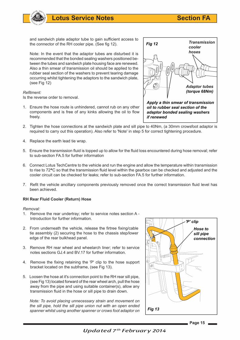
and sandwich plate adaptor tube to gain sufficient access to
the connector of the RH cooler pipe. (See fig 12).
Note: In the event that the adaptor tubes are disturbed it is
recommended that the bonded sealing washers positioned be-
tween the tubes and sandwich plate housing face are renewed.
Also a thin smear of transmission oil should be applied to the
rubber seal section of the washers to prevent tearing damage
occurring whilst tightening the adaptors to the sandwich plate,
(see Fig 12)
Refitment:
Is the reverse order to removal.
Ensure the hose route is unhindered, cannot rub on any other 1.
components and is free of any kinks allowing the oil to flow
freely.
Tighten the hose connections at the sandwich plate and sill pipe to 40Nm, (a 30mm crowsfoot adaptor is 2.
required to carry out this operation). Also refer to 'Note' in step 5 for correct tightening procedure.
Replace the earth lead tie wrap.4.
Ensure the transmission fluid is topped up to allow for the fluid loss encountered during hose removal; refer 5.
to sub-section FA.5 for further information
Connect Lotus TechCentre to the vehicle and run the engine and allow the temperature within transmission 6.
to rise to 72°C so that the transmission fluid level within the gearbox can be checked and adjusted and the
cooler circuit can be checked for leaks; refer to sub-section FA.5 for further information.
Refit the vehicle ancillary components previously removed once the correct transmission fluid level has 7.
been achieved.
RH Rear Fluid Cooler (Return) Hose
Removal:
Remove the rear undertray; refer to service notes section A - 1.
Introduction for further information.
From underneath the vehicle, release the firtree fixing/cable 2.
tie assembly (2) securing the hose to the chassis step/lower
edge of the rear bulkhead panel.
Remove RH rear wheel and wheelarch liner; refer to service 3.
notes sections GJ.4 and BV.17 for further information.
Remove the fixing retaining the 'P' clip to the hose support 4.
bracket located on the subframe, (see Fig 13).
Loosen the hose at it's connection point to the RH rear sill pipe, 5.
(see Fig 13) located forward of the rear wheel arch, pull the hose
away from the pipe and using suitable container(s), allow any
transmission fluid in the hose or sill pipe to drain down.
Note: To avoid placing unnecessary strain and movement on
the sill pipe, hold the sill pipe union nut with an open ended
spanner whilst using another spanner or crows foot adaptor on
'P' clip
Hose to
sill pipe
connection
Apply a thin smear of transmission
oil to rubber seal section of the
adaptor bonded sealing washers
if renewed
Adaptor tubes
(torque 68Nm)
Transmission
cooler
hoses
Fig 12
Fig 13
Updated 7th February 2014

Page 16
Lotus Service Notes Section FA
the hose connector when loosening or tightening.
From underneath the vehicle unbolt the RH fluid cooler hose 6.
(which will be the hose viewed on the left from inside the car)
from its connection at the sandwich plate. (See Fig 14).
The hose can now be removed from the vehicle be care-7.
fully feeding it out of the engine bay from the RH wheelarch
area.
Care point: Dependant upon the sandwich plate orientation it
may also be necessary to remove LH oil cooler pipe connector
and sandwich plate adaptor tube to gain sufficient access to
the connector of the RH cooler pipe. (See fig 15).
Note: In the event that the adaptor tubes are disturbed it is
recommended that the bonded sealing washers positioned
between the tubes and sandwich plate housing face are re-
newed.
Also a thin smear of transmission fluid should be applied to
the rubber seal section of the washers to prevent tearing dam-
age occurring whilst tightening the adaptors to the sandwich
plate.
To refit:
Refit is the reverse order to removal.
Ensure the hose route is unhindered, cannot rub on any other 1.
components and is free of any kinks allowing the oil to flow
freely.
2. Ensure that there is clearance between cooler hose and the
fuel filler neck to hose clip, see fig 16.
Tighten the hose connections at the sandwich plate and sill 3.
pipe to 40Nm (a 30mm crowsfoot adaptor is required to carry
out this operation). Also refer to 'Note' within step 5 of pipe
removal for the correct tightening procedure.
Ensure the transmission fluid is topped up to allow for the fluid 4.
loss encountered during hose removal; refer to sub-section
FA.5 for further information
Connect Lotus TechCentre to the vehicle and run the engine 5.
and allow the temperature within transmission to rise to 70°C
so that the transmission fluid level within the gearbox can be
checked and adjusted and the cooler circuit can be checked
for leaks; refer to sub-section FA.5 for further information.
Refit the vehicle ancillary components previously removed once the correct transmission fluid level has 6.
been achieved.
Fig 16 Fuel filler
hose clip
RH rear
cooler hose
Ensure there
is clearance
RH cooler hose
sandwich plate connection
Firtree
fixings
Powertrain
removed for clarity
Fig 14
Apply a thin smear of transmission
oil to rubber seal section of the
adaptor bonded sealing washers
if renewed
Adaptor tubes
(torque 68Nm)
Transmission
cooler
hoses
Fig 15
Updated 7th February 2014
Page 17
Lotus Service Notes Section FA
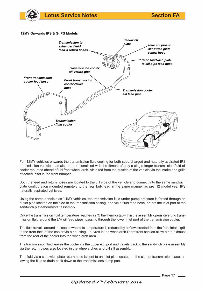
‘12MY Onwards IPS & S-IPS Models
For ‘12MY vehicles onwards the transmission fluid cooling for both supercharged and naturally aspirated IPS
transmission vehicles has also been rationalised with the fitment of only a single larger transmission fluid oil
cooler mounted ahead of LH front wheel arch. Air is fed from the outside of the vehicle via the intake and grille
attached inset in the front bumper.
Both the feed and return hoses are located to the LH side of the vehicle and connect into the same sandwich
plate configuration mounted remotely to the rear bulkhead in the same manner as pre ’12 model year IPS
naturally aspirated vehicles.
Using the same principle as ‘11MY vehicles, the transmission fluid under pump pressure is forced through an
outlet pipe located on the side of the transmission casing, and via a fluid feed hose, enters the inlet port of the
sandwich plate/thermostat assembly.
Once the transmission fluid temperature reaches 72°C the thermostat within the assembly opens diverting trans-
mission fluid around the L/H oil feed pipes, passing through the lower inlet port of the transmission cooler.
The fluid travels around the cooler where its temperature is reduced by airflow directed from the front intake grill
to the front face of the cooler via air ducting. Louvres in the wheelarch liners front section allow air to exhaust
from the rear of the cooler into the wheelarch area.
The transmission fluid leaves the cooler via the upper exit port and travels back to the sandwich plate assembly
via the return pipes also located in the wheelarches and LH sill assembly.
The fluid via a sandwich plate return hose is sent to an inlet pipe located on the side of transmission case, al-
lowing the fluid to drain back down to the transmissions sump pan.
Updated 7th February 2014
Rear sandwich plate
to sill pipe feed hose
Sandwich
plate Rear sill pipe to
sandwich plate
return hose
Front transmission
cooler feed hose Front transmission
cooler return
hoseTransmission cooler
sill feed pipe
Transmission cooler
sill return pipe
Transmission
fluid cooler
Transmission to
exhanger Fluid
feed & return hoses

Page 18
Lotus Service Notes Section FA
Transmission Fluid Cooler
Removal:
1. Remove the LHF wheel and wheelarch liner for to gain access to the
transmission cooler; refer to service notes sections GJ.4 and BV.17 for
further information.
2. Release the spring loaded hose clamps securing the fluid feed and
return link hoses to the inlet and outlet tubes of the cooler and discon-
nect the hoses from the cooler tubes.
4. Lower the hoses and allow the fluid from both hoses and the cooler to
drain into a suitable container, plug the cooler hose ports to minimize
fluid loss.
5. Release the M8 nuts and washers (4) securing the air ducting and the
transmission cooler at it mounting point studs to the bumper support
bracket.
6. The cooler and ducting assembly can now be withdrawn from the bumper
support bracket, ensure to collect the coolers combined compression
sleeves and bushes that may still remain on the mounting studs.
Fitment:
Place the cooler and duct into position (the main body of the duct as- -
sembly passing through the aperture within the bumper support bracket)
and the cooler and duct mounting holes fitted over the 4 mounting
point studs.
Care point: ensure the combined compression sleeves and mounting -
bushes are fitted in position within the oil cooler mounting holes before
refitting back onto the bumper support bracket mounting studs.
Refit the M8 nuts and washers (4) to the mounting studs and torque -
to 15Nm.
Push the fluid feed and return hoses back onto the cooler inlet -
and outlet tubes securing them in position with the spring loaded
hose clamps.
Ensure the hose route of both hoses is unhindered, cannot rub -
on other components and is free of any kinks allowing the oil
to flow freely.
Ensure the transmission fluid is topped up to allow for the fluid -
loss encountered during hose removal; refer to sub-section FA.5
for further information
Connect Lotus TechCentre to the vehicle and run the engine and -
allow the temperature within transmission to rise to 72°C so that
the transmission fluid level within the gearbox can be checked
and adjusted and the cooler circuit can be checked for leaks;
refer to sub-section FA.5 for further information.
Refit the vehicle ancillary components previously removed once -
the correct transmission fluid level has been achieved.
Updated 7th February 2014
Cooling
duct
M8 fixing
nuts/washers
Compression
sleeve/mounting
bushes
Bumper
support bracket
k125
Transmission fluid cooler k125
Fluid
return
hose
Fluid
feed
hose
Link pipe
hose clamps
k129
Page 19
Lotus Service Notes Section FA
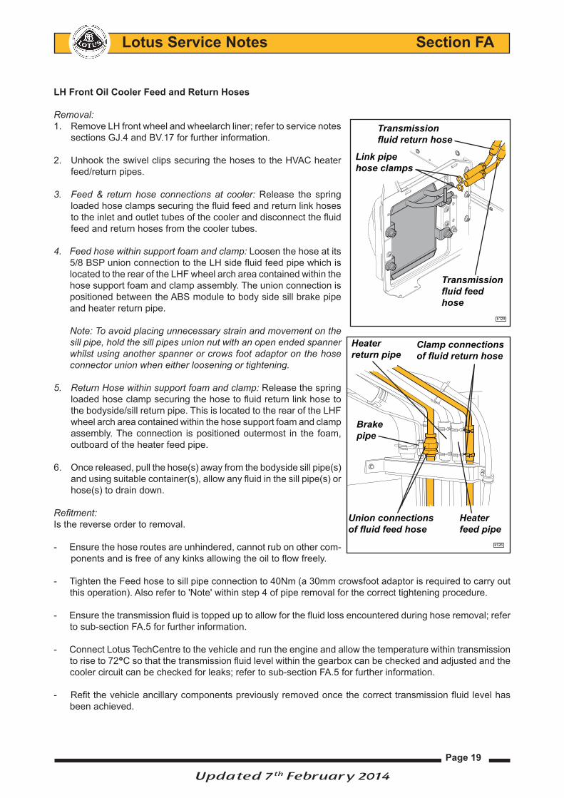
LH Front Oil Cooler Feed and Return Hoses
Removal:
Remove LH front wheel and wheelarch liner; refer to service notes 1.
sections GJ.4 and BV.17 for further information.
Unhook the swivel clips securing the hoses to the HVAC heater 2.
feed/return pipes.
Feed & return hose connections at cooler:3. Release the spring
loaded hose clamps securing the fluid feed and return link hoses
to the inlet and outlet tubes of the cooler and disconnect the fluid
feed and return hoses from the cooler tubes.
Feed hose within support foam and clamp:4. Loosen the hose at its
5/8 BSP union connection to the LH side fluid feed pipe which is
located to the rear of the LHF wheel arch area contained within the
hose support foam and clamp assembly. The union connection is
positioned between the ABS module to body side sill brake pipe
and heater return pipe.
Note: To avoid placing unnecessary strain and movement on the
sill pipe, hold the sill pipes union nut with an open ended spanner
whilst using another spanner or crows foot adaptor on the hose
connector union when either loosening or tightening.
Return Hose within support foam and clamp:5. Release the spring
loaded hose clamp securing the hose to fluid return link hose to
the bodyside/sill return pipe. This is located to the rear of the LHF
wheel arch area contained within the hose support foam and clamp
assembly. The connection is positioned outermost in the foam,
outboard of the heater feed pipe.
Once released, pull the hose(s) away from the bodyside sill pipe(s) 6.
and using suitable container(s), allow any fluid in the sill pipe(s) or
hose(s) to drain down.
Refitment:
Is the reverse order to removal.
Ensure the hose routes are unhindered, cannot rub on other com- -
ponents and is free of any kinks allowing the oil to flow freely.
Tighten the Feed hose to sill pipe connection to 40Nm (a 30mm crowsfoot adaptor is required to carry out -
this operation). Also refer to 'Note' within step 4 of pipe removal for the correct tightening procedure.
Ensure the transmission fluid is topped up to allow for the fluid loss encountered during hose removal; refer -
to sub-section FA.5 for further information.
Connect Lotus TechCentre to the vehicle and run the engine and allow the temperature within transmission -
to rise to 72°C so that the transmission fluid level within the gearbox can be checked and adjusted and the
cooler circuit can be checked for leaks; refer to sub-section FA.5 for further information.
Refit the vehicle ancillary components previously removed once the correct transmission fluid level has -
been achieved.
Updated 7th February 2014
Union connections
of fluid feed hose
Clamp connections
of fluid return hose
Brake
pipe
Heater
feed pipe
Heater
return pipe
k126
Link pipe
hose clamps
k129
Transmission
fluid feed
hose
Transmission
fluid return hose

Page 20
Lotus Service Notes Section FA
LH Rear Oil Cooler Feed and Return Hoses
Removal:
Remove the rear undertray; refer to service notes section A - Introduction for further information.1.
From underneath the vehicle, cut the tie-wraps (2) securing the 2.
feed and return hoses together and release the firtree fixing/cable
tie assembly (2) securing feed hose to the chassis step/lower edge
of the rear bulkhead panel.
Remove RH rear wheel and wheelarch liner; refer to service notes 3.
sections GJ.4 and BV.17 for further information.
Feed Hose:4. Removal of the feed hose through the wheelarch area
may be easier with the removal of the air filter housing and charcoal
canister assembly and cosmetic engine cover support brace; refer
to service notes sections EJ.4 and LN.8 for further information.
- From the wheelarch area, remove the M6 x 16 screw retaining the
'P' clip to the hose support bracket located on the subframe,
- Release the hose at its 5/8 BSP connection point to the RH rear sill pipe.
Note: To avoid placing unnecessary strain and movement on the sill
pipe, hold the sill pipes union nut with an open ended spanner whilst
using another spanner or crows foot adaptor on the hose connector
union when either loosening or tightening.
Return Hose:5. Release the spring loaded hose clamp securing the
hose to fluid return link hose to the bodyside/sill return pipe. This is
located to the rear of the LHF wheel arch area.
Pull the hose(s) away from the pipe(s) and use suitable container(s), al-6.
lowing any transmission fluid in the hose(s) or pipe(s) to drain down.
Sandwich Plate Connections:7. From underneath the vehicle release
the 5/8 BSP connector union(s) securing the hose(s) to the sandwich
plate. Note: the union closest to the bulkhead is for the feed hose, the
union closest to the transmission is for the return hose.
Refitment:
Is the reverse order to removal.
Ensure the hose routes are unhindered, cannot rub on other components and is free of any kinks allowing -
the oil to flow freely.
Tighten the Feed hose to sill pipe connection to 40Nm (a 30mm crowsfoot adaptor is required to carry out -
this operation). Also refer to 'Note' within step 4 of pipe removal for the correct tightening procedure.
Ensure the transmission fluid is topped up to allow for the fluid loss encountered during hose removal; refer -
to sub-section FA.5 for further information.
Connect Lotus TechCentre to the vehicle and run the engine and allow the temperature within transmission -
to rise to 72°C so that the transmission fluid level within the gearbox can be checked and adjusted and the
cooler circuit can be checked for leaks; refer to sub-section FA.5 for further information.
Refit the vehicle ancillary components previously removed once the correct transmission fluid level has -
been achieved.
Updated 7th February 2014
Union connections
of fluid feed hose
Clamp connection
of fluid return hose
'P' Clip
fixing
k127
Sandwich plate
assembly
Fluid feed
connection
Fluid return
connection
Tie wraps
Return hose to
transmission
Feed hose
from
transmission
k128

Page 21
Lotus Service Notes Section FA
FA.5 - TRANSMISSION FLUID LEVEL CHECKING, ADJUSTMENT AND DRAINING
Fluid temperature check & adjustment
The Toyota U660E transmission assembly used on the Evora IPS requires the transmission fluid to be within
a specific temperature range and with the engine running before it is possible to accurately check and adjust
the fluid level.
An accurate level reading within the transmission can only be taken under normal driving conditions which
requires the fluid to be at a specific temperature as well as ensuring that the fluid has completely circulated
around the transmission cooling system, i.e. the external oil lines and cooler(s).
Note: Checking and adjusting the transmission fluid level under any other conditions could result in it being
under or overfilled which could cause drivability issues and damage to the transmission.
Checking Fluid Temperature
Ensure that electrical systems such as the a.c system, audio system and lighting system are off.1.
Connect Lotus TechCentre to the vehicle select EMS live data and scroll down to the ‘Oil Temperature’ option 2.
(see screen shots below).
Start the engine and allow the temperature within the gearbox to rise to 70º + so that the thermostat in the 3.
sandwich plate assembly opens allowing the transmission fluid to circulate around the oil cooler system.
Note: a fluid temperature reading of 70º and over is required for the thermostat to open. To raise the fluid
temperature it may be necessary to drive the vehicle for a distance of not less than 10 miles (16 km).
The transmission fluid level is measured with the fluid temperature at 40º centigrade. •
Note: Because the transmission fluid has circulated
around the cooler system it's temperature will
probably now be in excess of 40°C (104°F) or
more, turn the ignition switch off and wait until the
fluid temperature drops below 45°C (113°F) and
proceed to level checking procedure as described
on the following page.
If the fluid temperature drops below 40°C then it
will necessary to follow out steps a - d shown below
before proceeding to the level checking procedure.
Depress and hold down the brake pedal.a.
Start the engine.b.
Slowly select P R N D buttons from the selector c.
allowing the transmission enough time to select
each gear, and then go back to P. Slowly selecting
PRND will allow enough time for the fluid to circulate
through each part of the transaxle.
Dependant upon current transmission fluid d.
temperature as well as ambient temperature it
may be necessary to drive the vehicle for a short
distance to bring the transmission fluid up to 40°C.
Once you are certain that the sandwich plate thermostat has opened allowing the transmission fluid to circulate
completely around the external cooling system have then allowed the fluid temperature to drop to 40°C you
can then check the fluid level as described on the next page.

Page 22
Lotus Service Notes Section FA
transmission fluid level check and adjustment.With the transmission fluid at temperature of 40°C (104°F):
Remove the rear undertray; refer to Service Notes introduction 1. section for further information.
Lower vehicle and restart engine with park selected.2.
Raise the vehicle and from underneath:3.
Place a clean and dry container underneath the transmission level/• overflow plug area (situated in the transmission sump). Fig A.
Using a 6 mm hexagon drive socket, remove the transmission • overflow plug and gasket.
Be aware that the fluid that may drain out will be hot.
Check the amount of fluid that drains out of the overflow plug hole.4.
If only a small amount of fluid (approximately 1 cc) is drained, this is • an indication that only residual fluid remaining in the overflow tube, (fig B) has come out. This does not mean that the transmission is overfilled therefore transmission fluid will need to be added continue from step 5.
If a larger amount of fluid is drained out, (fig D), then wait for the • fluid flow to slow down to a drip, (fig C). Then proceed straight to step 7.
Adjusting fluid level using transmission refill plug (if accessible)5.
With the engine running:
Remove the refill plug and gasket located on the end of the • transmission case, Fig E. Note: The plug is accessible with the L/H rear wheelarch liner removed; refer to Service Notes section BV.17 for further information.
Add fluid through the refill hole, a list of approved oils can be found • in Evora Service Notes, section OK - Maintenance & Lubrication which can be viewed from the Lotus Dealer Portal at http://dealers.lotuscars.com.
Continue to add fluid whilst the engine is running until it flows out • (as per fig D) wait for it to slow down to a drip (as per fig C), then refit overflow plug. (Torque to 40 Nm) then go to straight to step 7.
Adjusting fluid level using speedometer blanking plug (if refill plug 6. is inaccessible )
Turn the engine off.
Place a clean and dry container underneath • the transmission level/drain plug area.
Updated 07th January 2013
A
Level/overflowplug
B Fluid level
Overflowtube
C
large flow from overflow tube
Transmissionrefill plug
f159
f159
f159
f159
E
D
f159

Page 23
Lotus Service Notes Section FA
Refit overflow plug (torque to 40 Nm). •
Remove the air intake hose and plenum • assembly to gain access to the speedometer drive blanking plug, Fig F. This is located on top of the transmission case, remove blanking plug fixing, plug and ‘O’ ring.
Add a set quantity of fluid (0.5 -1.0 litre) • through the speedometer drive hole. Fig G.
Refit air intake hose and plenum assembly.•
Start engine and leave to idle for 1 minute • to allow the fluid to circulate around the transmission.
Remove the overflow plug whilst the engine • is running. If fluid flows out (as per fig D) wait for it to slow down to a drip (as per fig C), then refit overflow plug. (Torque to 40 Nm) then go to straight to step 7.
If fluid did not flow out, then additional fluid • will need to be added. Repeat step 6 again until enough fluid has been added so that it will flow out of the overflow plug before proceeding to step 7.
Refit overflow plug and fit a new gasket, 7. (torque to 40 Nm) or;
Refit speedometer blanking plug and fit a 8. new ‘O’ ring (torque to 5.5 Nm).
Install refill plug and fit a new gasket, (torque 9. to 49 Nm).
Refit the undertray, wheelarch liner and 10. road wheel (if removed).
Updated 07th February 2014
G.
f159
F
Blanking plug fixing
f161

Page 24
Lotus Service Notes Section FA
Draining transmission fluidIt is recommended to drain the transmission fluid from the oil pan assembly prior to carrying out certain operations such as powertrain removal, driveshaft removal etc.
. Remove the rear undertray and LHR wheelarch liner - see service notes introduction section and BV.17 for further information.
. From the LHR wheelarch area remove the transmission refill plug and gasket, (torque to 49 Nm) see fig A.
Note: if the refill plug is not accessible then the speedometer drive blanking plug can be removed instead (see previous page).
. Place a clean and dry container underneath the transmission level/overflow plug area (situated in the transmission sump).
. Using a 6 mm hexagon drive socket, remove the transmission level/overflow plug and gasket (torque 40 Nm) see fig B.
Be aware that the fluid that may drain out will be hot. . With the drain plug removed the transmission oil tube is now acces-
sible. Using a 6mm hexagon socket wrench, remove the tube and drain the transmission fluid, see fig C.
Be aware that up to 3 litres of hot fluid that may drain out.
. Once drained refit the transmission oil tube (torque 2 Nm) and tem-porarily refit the refill plug and overflow plug.
initial filling. Remove the refill plug and gasket located on the end of the transmission
case, see fig A.
. Remove the level/overflow plug located in the sump pan, see fig B.
. Add transmission fluid through the refill hole, a list of approved oils can be found in Evora Service Notes, section OK - Maintenance & Lubrication. Continue to add fluid until it begins to flow out of the overflow plug hole wait for it to slow down to a drip.
. Temporarily refit overflow plug then carry out the transmission fluid level check and adjustment procedure as described on the previous page to ensure that fluid has completely circulated around the cooling system and that the correct fluid level has been achieved.
Updated 31st January 2013
Transmissionrefill plug
Level/overflowplug
Level/drainplug
Hexagonsocket
f159
f159
f159
A
B
C
NOTICE
NOTICE

Page 25
Lotus Service Notes Section FA
FA.6 - IGNITION SWITCH AND BATTERY DISCONNECTION
ignition SwitchThe Auto ignition switch incorporates solenoid, which, when energised prevents the switch being returned to the fully off position. As the ignition is turned off, the TCU via pin 73 grounds the key interlock solenoid within the ignition lock. This physically prevents the key barrel being turned back to the fully off position to remove the key.
Once P – Park has been selected from the PRND selector console and the transmission is in park the TCU will de-energise the key interlock solenoid & allow the key to be turned to the fully off position of the lock travel and the key can be withdrawn from the lock barrel.
As the vehicle has Auto Park the transmission will (provided vehicle is stationary) go straight into park when the ignition is turned off, making the interlock system hard to notice as the vehicle will have gone into park before the driver can get to the key removal stage.
However if the driver attempts to remove the key while the vehicle is still moving then the TCU would activate the key interlock solenoid, thereby preventing key removal until the vehicle was stationary and in park.
Disconnecting the BatteryThe transmission will default to P- Park rendering the vehicle immobile if the battery is disconnected or becomes discharged.
Updated 07th January 2013

Page 26
Lotus Service Notes Section FA
FA.7 - VEHICLE RECOVERY AND TOWING
Vehicle towingThe recommended method of recovery is the use of a flat bed trans-porter as shown in illustration (c).
If towing is necessary, we recommend it is carried out by your Lotus dealer or a professional vehicle recovery service.
The Evora fitted with IPS transmission must be towed in the methods shown in illustrations (a - b).
If towing using the method shown in illustration (a) then a towing dolly must be placed under the rear wheels.
Never use the recovery eye to tow the vehicle.
Never tow a vehicle with an IPS gearbox with the driving wheels rotating on the ground, as this may cause serious damage to the transmission.
Comply with all local legislation applicable to cars being towed.
recovery eyeA recovery eye is provided with the vehicle tool kit, and stowed in the rear luggage compartment. When re-quired, fit the eye to its anchorage point in the top left hand corner of the radiator air intake aperture, having first removed the protective bung (if fitted), and screw fully into the tapped boss.
The eye is provided to aid vehicle recovery, such as winching onto a flatbed car transporter, but only when the car is able to roll freely.
Preparation for winching:
Ensure that the vehicles battery is connected and has sufficient charge.•
Turn the ignition key to position II so that the PRND selector buttons can be activated.•
Release the parking brake and ensure that the transmission is in N - Neutral.•
If Neutral cannot be selected then towing dollies must be placed under the rear wheels before winching the • vehicle.
Updated 07th January 2013
a
b
c
NOTICE
NOTICE
NOTICE

Page 27
Lotus Service Notes Section FA
FL.8 - TRANSMISSION DIAGNOSTIC TROUBE CODES
Transmission Malfunction Indicator (amber)
The transmission warning light is illuminated if a fault is detected within the transmission, an associated control component or if the transmission oil exceeds its recommended maximum temperature.
A bulb check will light the lamp for about 3 seconds following ignition switch on.
If the temperature of the transmission becomes too high the vehicle will default to a limited power mode • and the Transmission Malfunction Indicator lamp will flash.If a fault is detected within the transmission, an associated component or if transmission oil temperature • continues to rise, then the Transmission Malfunction Indicator lamp will illuminate or flash continuously. Reduce speed immediately and adopt a moderate driving style.If a fault is detected within a transmission component which could affect the vehicles emissions, then the • engine Malfunction Indicator Lamp (MIL) will also illuminate continuously. Even if the Transmission Malfunction Indicator lamp extinguishes, proceed with caution and seek dealer • advice without delay and avoid all unnecessary journeys.
NOTICE Continuing to drive with an illuminated Transmission Malfunction Indicator lamp may cause dam-age to the transmission. Depending upon the cause, frequency and duration of the tell tale illumination it may be necessary to renew the transmission fluid even if all monitored transmission components are operating correctly.
A 'stand alone' lap top PC loaded with 'Lotus Techcentre' software allows the CAN based serial data to be read (see section Engine Management section EMR.5 for further information).
DiAgNoStic trouBLe coDe (Dtc) LiSt
Dtc Fault description PageP0218 Transmission Fluid Over Temperature Condition 29P0500 Vehicle Speed Sensor "A" 29P0562 System Voltage Low 30P0563 System Voltage High 30P0601 Internal Control Module Memory Check Sum Error 30 P060A Internal Control Module Monitoring Processor Performance 30P0610 Control Module Vehicle Options Error 31P0613 TCM Processor 31P0705 Transmission Range Sensor "A" Circuit (PRNDL Input) 31P0710 Transmission Fluid Temperature Sensor "A" Circuit 31P0712 Transmission Fluid Temperature Sensor "A" Circuit Low 32 P0713 Transmission Fluid Temperature Sensor "A" Circuit High 33P0717 Input / Turbine Speed Sensor "A" Circuit No Signal 33P0718 Input / Turbine Speed Sensor "A" Circuit Intermittent 33P0719 Brake Switch "B" Circuit Low 34P0721 Output Speed Sensor Circuit Range / Performance 34P0722 Output Speed Sensor Circuit No Signal 34P0723 Output Speed Sensor Circuit Intermittent 34P0724 Brake Switch "B" Circuit High 34P0741 Torque Converter Clutch Circuit Performance or Stuck Off 36P0746 Pressure Control Solenoid "A" Performance or Stuck Off (SLT) 37P0748 Pressure Control Solenoid "A" Electrical 38P0751 Shift Solenoid "A" Performance or Stuck Off 38P0753 Shift Solenoid "A" Electrical 41
Continued.....
All new lamps highlighted, remaining lamps are carry over from MY08 although some
positions may have changed.
SIDE LAMP ON GCC OVER SPEED SPORT TRANSMISSION
FAILURE
(MMT/AUTO)
ESC/ESC OFF CRUISE CONTROL COOLANT
TEMPERATURE
Blue start up
Red if it gets too
hot
Updated 7th February 2014

Page 28
Lotus Service Notes Section FA
Dtc Fault description PageP0756 Shift Solenoid "B" Performance or Stuck Off 39P0758 Shift Solenoid "B" Electrical 41P0761 Shift Solenoid "C" Performance or Stuck Off 40P0763 Shift Solenoid "C" Electrical 41P0766 Shift Solenoid "D" Performance or Stuck Off 40P0768 Shift Solenoid "D" Electrical 41P0812 Reverse Input Circuit 41P0813 Reverse Output Circuit 42P081C Park Input Circuit 41P081D Neutral Input Circuit 41P0842 Transmission Fluid Pressure Sensor/Switch "A" Circuit Low 42P0843 Transmission Fluid Pressure Sensor/Switch "A" Circuit High 43P0847 Transmission Fluid Pressure Sensor/Switch "B" Circuit Low 43P0848 Transmission Fluid Pressure Sensor/Switch "B" Circuit High 44P0853 Drive Switch Input Circuit 41P0872 Transmission Fluid Pressure Sensor/Switch "C" Circuit Low 43P0873 Transmission Fluid Pressure Sensor/Switch "C" Circuit High 45P0886 TCM Power Relay Control Circuit Low 45P1613 Forced Mechanical Limphome Position 46P1657 Ignition Key Lock Solenoid Control Circuit 46 P172A Forced Gear Neutral 47P1780 Safety Processor: Neutral select failed 47P1801 Park Position Feedback Switch Circuit Low 47P1802 Park Position Feedback Switch Circuit High 47P1803 Reverse Position Feedback Switch Circuit Low 48P1804 Reverse Position Feedback Switch Circuit High 48P1805 Neutral Position Feedback Switch Circuit Low 48P1806 Neutral Position Feedback Switch Circuit High 48P1807 Drive Position Feedback Switch Circuit Low 49P1808 Drive Position Feedback Switch Circuit High 49P185A Safety Processor Communications Fault: Safety to Main direction 49P1860 Safety Processor Communications Fault: Main to Safety direction 49P1904 Park Position Select Error – Incorrect feedback switch 50P1905 Reverse Position Select Error – Incorrect feedback switch 50P1906 Neutral Position Select Error – Incorrect feedback switch 50P1907 Drive Position Select Error – Incorrect feedback switch 50P1909 Transmission Range Selector Position Control Error 50P1910 Transmission Range Selector Motor Driver 50P1911 Transmission Range Selector Excessive Lost Motion 50P1912 Transmission Range Selector Motor Circuit Low 50P1913 Transmission Range Selector Motor Circuit High 50P1921 Safety Processor: Incorrect selection of Drive 52 P1925 Safety Processor: Incorrect selection of Reverse 52P1929 Transmission Range Selector Solenoid Performance 50P1930 Transmission Range Selector Solenoid Control Circuit Low 53P1931 Transmission Range Selector Solenoid Control Circuit High 53P2757 Torque Converter Clutch Pressure Control Solenoid Control Circuit Performance or Stuck Off 54P2759 Torque Converter Clutch Pressure Control Solenoid Control Circuit Electrical 54P2769 Torque Converter Clutch Circuit Low 55P2770 Torque Converter Clutch Circuit High 55P2800 Transmission Range Sensor "B" Circuit (PRNDL Input) 56P2805 Transmission Range Sensor "A"/"B" Correlation 57U0100 Lost Communication with ECM/PCM “A” 57U0122 Lost Communication with Vehicle Dynamics Control Module 57
Continued.....
Updated 7th January 2013
Page 29
Lotus Service Notes Section FA
Dtc Fault description PageU0123 Lost Communication with Yaw Rate Sensor Module 57U0126 Lost Communication with Steering Angle Sensor Module 58U0155 Lost Communication with Instrument Panel Cluster (IPC) Control Module 58U0301 Software Incompatibility with ECM/PCM “A” 59U0401 Invalid Data Received from ECM/PCM “A” 59U0513 Invalid Data Received from Yaw Rate Sensor Module 59
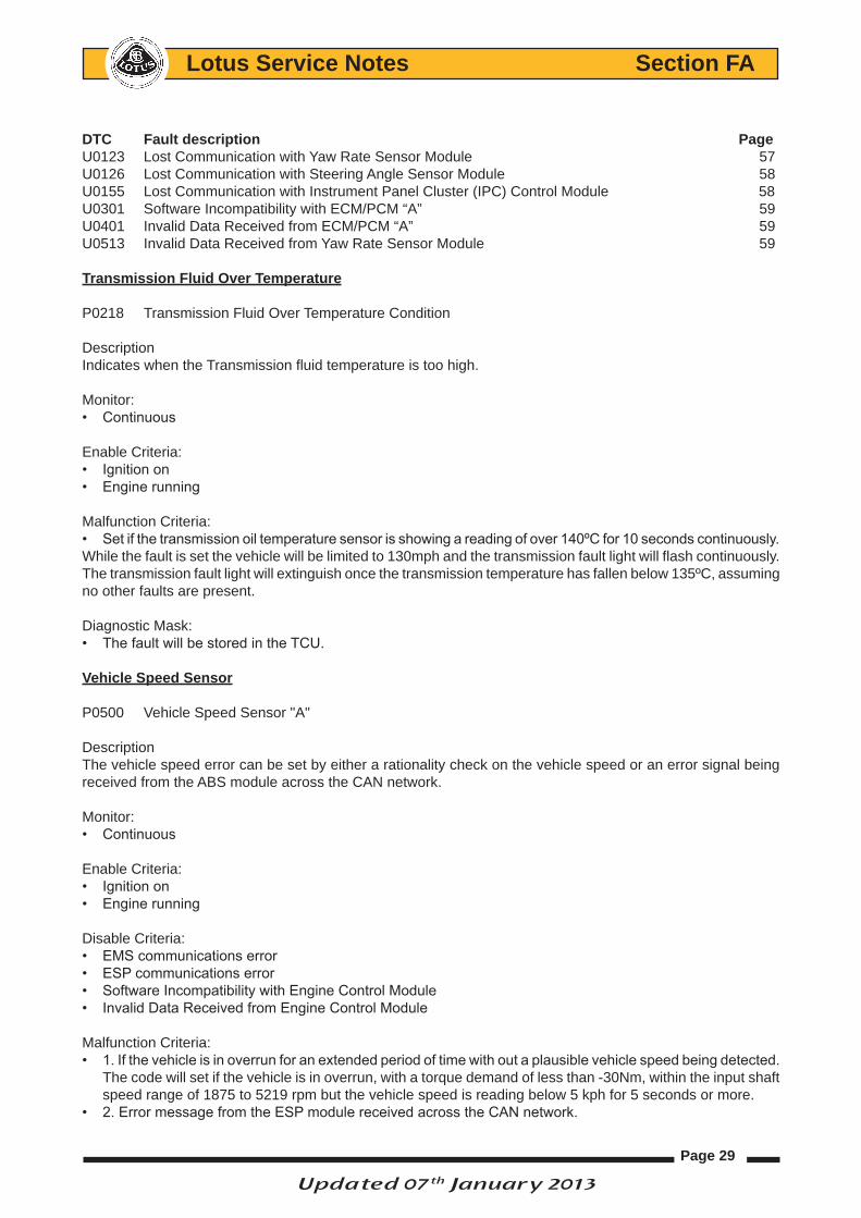
transmission Fluid over temperature
P0218 Transmission Fluid Over Temperature Condition
DescriptionIndicates when the Transmission fluid temperature is too high.
Monitor: • Continuous
Enable Criteria: • Ignition on• Engine running
Malfunction Criteria: • Set if the transmission oil temperature sensor is showing a reading of over 140ºC for 10 seconds continuously. While the fault is set the vehicle will be limited to 130mph and the transmission fault light will flash continuously. The transmission fault light will extinguish once the transmission temperature has fallen below 135ºC, assuming no other faults are present.
Diagnostic Mask:• The fault will be stored in the TCU.
Vehicle Speed Sensor
P0500 Vehicle Speed Sensor "A"
DescriptionThe vehicle speed error can be set by either a rationality check on the vehicle speed or an error signal being received from the ABS module across the CAN network.
Monitor: • Continuous
Enable Criteria: • Ignition on• Engine running
Disable Criteria: • EMS communications error• ESP communications error• Software Incompatibility with Engine Control Module• Invalid Data Received from Engine Control Module
Malfunction Criteria: • 1. If the vehicle is in overrun for an extended period of time with out a plausible vehicle speed being detected.
The code will set if the vehicle is in overrun, with a torque demand of less than -30Nm, within the input shaft speed range of 1875 to 5219 rpm but the vehicle speed is reading below 5 kph for 5 seconds or more.
• 2. Error message from the ESP module received across the CAN network.
Updated 07th January 2013

Page 30
Lotus Service Notes Section FA
Potential Failure mode:• Faulty speed sensor• Error state in the ESP module
Diagnostic Mask:• The TCU fault light and ECU MIL will be illuminated if fault is present.
System Voltage
P0562 System Voltage LowP0563 System Voltage High
DescriptionWith a battery and alternator functioning as normal the system voltage for a running engine should be around 14V. The TCU monitors this and will diagnose if the voltage is too high or too low.
Monitor: • Continuous
Enable Criteria: • Ignition on• Engine running
Disable Criteria: • EMS communications error• Software Incompatibility with Engine Control Module• Invalid Data Received from Engine Control Module
Malfunction Criteria: • P0562 The fault will set if the battery voltage drops below 10V for longer than 10 seconds• P0563 The fault will set if the battery voltage goes over 16V for longer than 10 seconds.
Potential Failure mode:• Alternator fault• Battery fault
Diagnostic Mask:• The TCU fault light and ECU MIL will be illuminated if fault is present.
tcu integrity
P0601 Internal Control Module Memory Checksum ErrorP0613 TCM Processor
DescriptionThis code is used by the TCU to check the integrity of the software and calibration data. P0601 checks that on power up the checksum for calibration data is the same as checksum saved on the previous power down.
P0613 checks the watchdog timer after a defined period to see if it has reset. If the watchdog timer has not reset then the code has entered an unplanned loop or condition stopping it resetting the timer.
Monitor• P0601 at TCU power up• P0613 continuously while the engine running
Updated 07th January 2013
Page 31
Lotus Service Notes Section FA
Diagnostic Mask:• The TCU fault light and ECU MIL will be illuminated if fault is present.
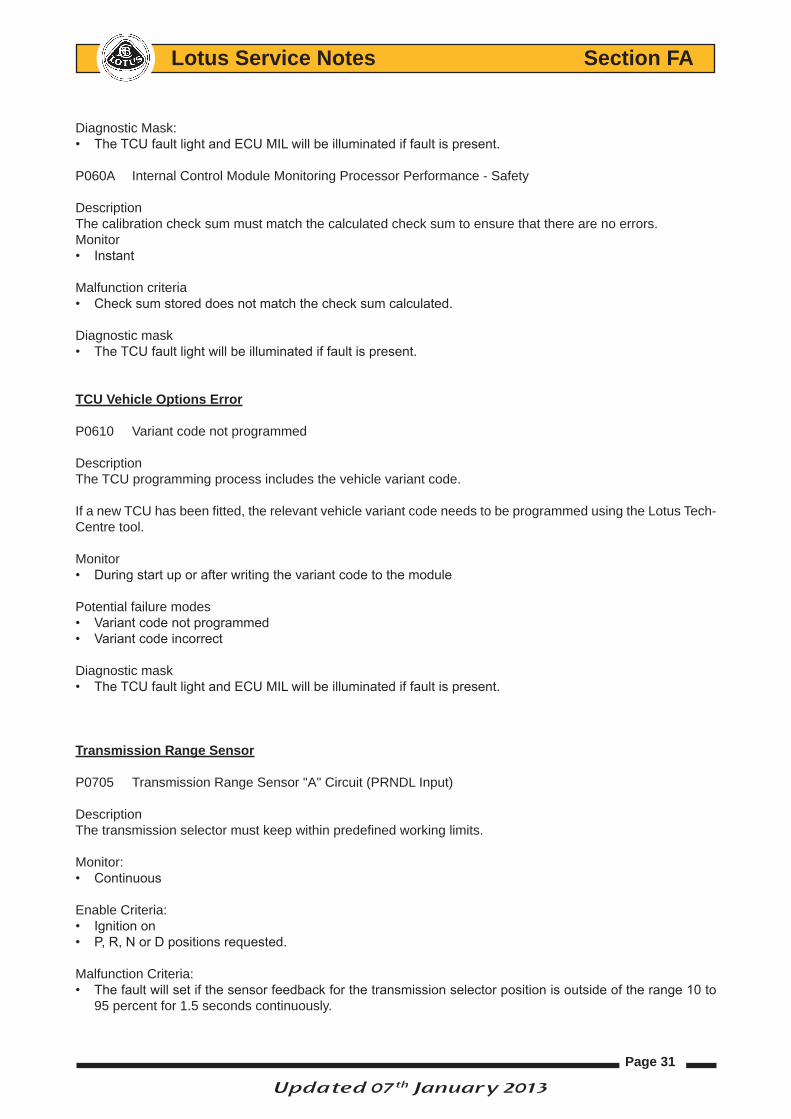
P060A Internal Control Module Monitoring Processor Performance - Safety
DescriptionThe calibration check sum must match the calculated check sum to ensure that there are no errors. Monitor• Instant
Malfunction criteria• Check sum stored does not match the check sum calculated.
Diagnostic mask• The TCU fault light will be illuminated if fault is present.
tcu Vehicle options error
P0610 Variant code not programmed
DescriptionThe TCU programming process includes the vehicle variant code.
If a new TCU has been fitted, the relevant vehicle variant code needs to be programmed using the Lotus Tech-Centre tool.
Monitor• During start up or after writing the variant code to the module
Potential failure modes• Variant code not programmed• Variant code incorrect
Diagnostic mask• The TCU fault light and ECU MIL will be illuminated if fault is present.
transmission range Sensor
P0705 Transmission Range Sensor "A" Circuit (PRNDL Input)
DescriptionThe transmission selector must keep within predefined working limits.
Monitor: • Continuous
Enable Criteria: • Ignition on• P, R, N or D positions requested.
Malfunction Criteria: • The fault will set if the sensor feedback for the transmission selector position is outside of the range 10 to
95 percent for 1.5 seconds continuously.
Updated 07th January 2013

Page 32
Lotus Service Notes Section FA
Diagnostic Mask:• The TCU fault light will be illuminated if fault is present.
transmission Fluid temperature
P0710 Transmission Fluid Temperature Sensor "A" CircuitP0712 Transmission Fluid Temperature Sensor "A" Circuit LowP0713 Transmission Fluid Temperature Sensor "A" Circuit High
DescriptionA rationality check for monitoring the temperature sensor performance.
P0710
Monitor: • Continuous
Enable Criteria: • Ignition on
Disable Criteria: • Transmission fluid temperature sensor "A" circuit low• Transmission fluid temperature sensor "A" circuit high
Malfunction Criteria: • The sensor detects an apparent change in temperature from 28ºC to 75ºC or from 75ºC to 28ºC in less than
1 second.
Potential Failure Modes:• Open or short in the sensor circuit• Sensor fault• TCU fault
Diagnostic Mask:• The TCU fault light and ECU MIL will be illuminated if fault is present.
P0712
Monitor: • Continuous
Enable Criteria: • Ignition on
Malfunction Criteria: • If the sensor feed back voltage is very low for longer than 1.5 seconds. The sensor feed back is inversely
proportional to temperature, so relates to a high temperature.
Potential Failure Modes:• Open sensor circuit• Sensor fault• TCU fault
Diagnostic Mask:• The TCU fault light and ECU MIL will be illuminated if fault is present.
Updated 07th January 2013

Page 33
Lotus Service Notes Section FA
P0713
Monitor: • Continuous
Enable Criteria: • Ignition on• Communication with IP• Ambient air temperature sensor feed back greater than -30ºC
Malfunction Criteria: • If the sensor feed back voltage is very high for longer than 1.5 seconds. The sensor feed back is inversely
proportional to temperature, so relates to a low temperature.
Potential Failure Modes:• Short in the sensor circuit• Sensor fault• TCU fault
Diagnostic Mask:• The TCU fault light and ECU MIL will be illuminated if fault is present.
turbine Speed Sensor
P0717 Input Shaft Speed Sensor "A" Circuit No SignalP0718 Input Shaft Speed Sensor "A" Circuit Intermittent
DescriptionA rationality check for the input shaft speed sensor
P0717
Monitor: • Continuous
Enable Criteria: • Ignition on• Engine running• Battery voltage over 8 volts• In gear 2 or higher
Malfunction Criteria: • The output shaft speed is reading greater than 1000rpm while the input shaft speed is less than 300rpm for
5 seconds.
Potential Failure Modes:• Sensor fault• TCU fault
Diagnostic Mask:• The TCU fault light and ECU MIL will be illuminated if fault is present.
P0718
Monitor: • Continuous
Updated 07th January 2013
Page 34
Lotus Service Notes Section FA
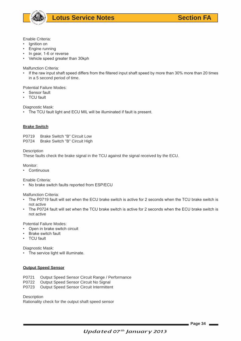
Enable Criteria: • Ignition on• Engine running• In gear, 1-6 or reverse• Vehicle speed greater than 30kph
Malfunction Criteria: • If the raw input shaft speed differs from the filtered input shaft speed by more than 30% more than 20 times
in a 5 second period of time.
Potential Failure Modes:• Sensor fault• TCU fault
Diagnostic Mask:• The TCU fault light and ECU MIL will be illuminated if fault is present.
Brake Switch
P0719 Brake Switch "B" Circuit LowP0724 Brake Switch "B" Circuit High
DescriptionThese faults check the brake signal in the TCU against the signal received by the ECU.
Monitor: • Continuous
Enable Criteria: • No brake switch faults reported from ESP/ECU
Malfunction Criteria: • The P0719 fault will set when the ECU brake switch is active for 2 seconds when the TCU brake switch is
not active • The P0724 fault will set when the TCU brake switch is active for 2 seconds when the ECU brake switch is
not active
Potential Failure Modes:• Open in brake switch circuit• Brake switch fault• TCU fault
Diagnostic Mask:• The service light will illuminate.
output Speed Sensor
P0721 Output Speed Sensor Circuit Range / PerformanceP0722 Output Speed Sensor Circuit No SignalP0723 Output Speed Sensor Circuit Intermittent
DescriptionRationality check for the output shaft speed sensor
Updated 07th January 2013

Page 35
Lotus Service Notes Section FA
P0721Monitor: • Continuous
Enable Criteria: • Ignition on• Vehicle speed is 15kmh or more
Disable criteria• DCF0722 has failed• Force mechanical limp home• Force neutral state• Vehicle speed senor error is present• Output shaft speed error has been detected• Shift solenoid error has occurred
Malfunction Criteria: • P0721 compares the output shaft speed to the calculated output shaft speed, if the error is over 10% for 2
seconds the fault will set
Potential Failure Modes:• Sensor fault• TCU fault
Diagnostic Mask:• The TCU fault light and ECU MIL will be illuminated if fault is present.
P0722
Monitor: • Continuous
Enable Criteria: • Ignition on• Engine running• Vehicle speed is 5kmh or more• Vehicle battery voltage must be above 8 volts• Vehicle driving in gear 2 or higher
Malfunction Criteria: • The output speed sensor is showing output speed of less than 100 rpm while the vehicle is travelling at
10kmh or greater for 10 seconds.
Potential Failure Modes:• Sensor fault• TCU fault
Diagnostic Mask:• The TCU fault light and ECU MIL will be illuminated if fault is present.
P0723
Monitor: • Continuous
Enable Criteria: • Ignition on
Updated 07th January 2013

Page 36
Lotus Service Notes Section FA
• Engine running for greater than 5 seconds• Vehicle speed is 20kmh or more• Vehicle driving in gear 1 – 6, reverse or neutral.
Disable criteria• DCF0722 has failed• Force mechanical limp home• Force neutral state• Vehicle speed senor error is present• Output shaft speed error has been detected• Shift solenoid error has occurred
Malfunction Criteria: • The fault will set when the difference between the raw output shaft speed and the filtered number is greater
than 30% 20 times in a 5 second period of time.
Potential Failure Modes:• Sensor fault• TCU fault
Diagnostic Mask:• The TCU fault light and ECU MIL will be illuminated if fault is present.
torque converter clutch
P0741 Torque Converter Clutch Circuit Performance or Stuck Off
DescriptionThe torque converter is able to lock the engine to the input shaft. This fault is used to detect when the torque convertor is commanded locked, but a speed difference is detected between the engine speed and the input shaft speed, suggesting that it is unlocked.
Monitor: • Continuous
Enable Criteria: • Ignition on• Engine running• In gear 2 or higher• In gear duration greater than 2 seconds• Vehicle speed over 10kph• Torque demand over 25Nm• No lateral G inhibit • Auto transmission oil greater than 25C• SLU solenoid request is greater than 60% • SL solenoid request is greater than 95% • Input shaft speed greater than 100rpm• Slip across the torque convertor over 60rpm
Malfunction Criteria: • The fault will set if a difference across the torque convertor of greater than 60 rpm when the clutch is com-
manded shut and the SLU pressure switch is on.
Potential Failure Modes:• Torque converter stuck • Valve body is blocked• Line pressure is low
Updated 07th January 2013
Page 37
Lotus Service Notes Section FA
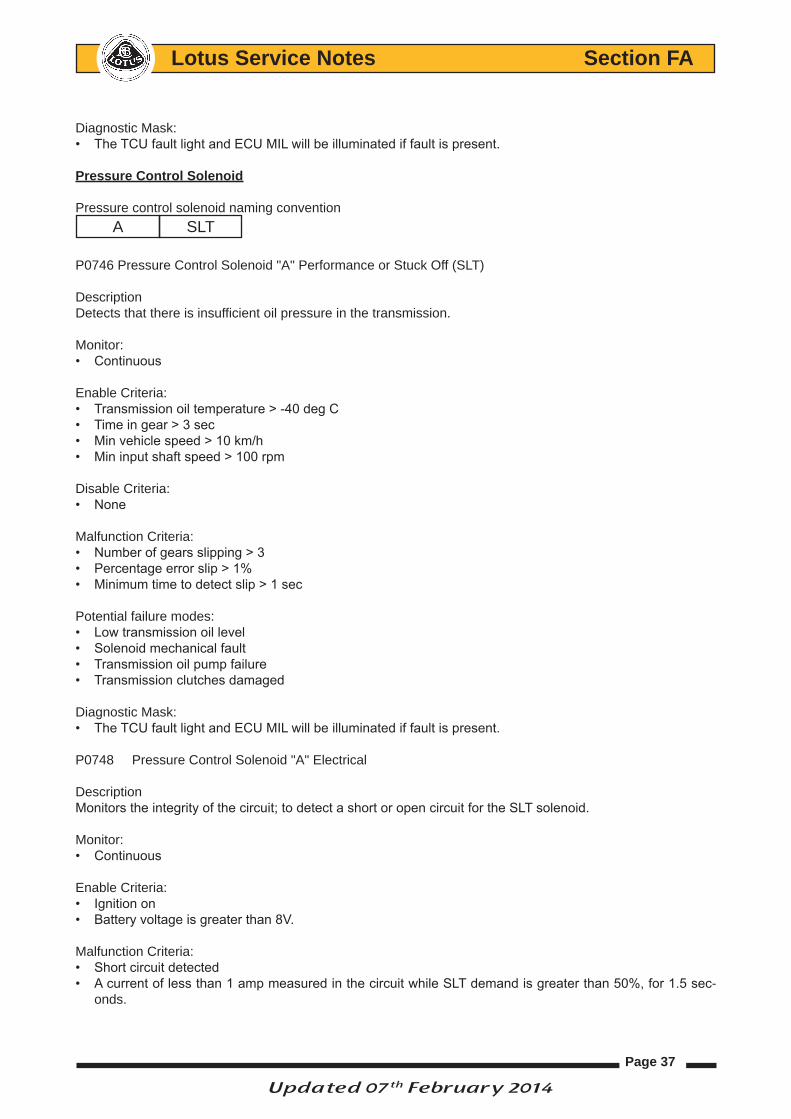
Diagnostic Mask:• The TCU fault light and ECU MIL will be illuminated if fault is present.
Pressure control Solenoid
Pressure control solenoid naming conventionA SLT
P0746 Pressure Control Solenoid "A" Performance or Stuck Off (SLT)
DescriptionDetects that there is insufficient oil pressure in the transmission.
Monitor:• Continuous
Enable Criteria:• Transmission oil temperature > -40 deg C• Time in gear > 3 sec• Min vehicle speed > 10 km/h• Min input shaft speed > 100 rpm
Disable Criteria:• None
Malfunction Criteria:• Number of gears slipping > 3• Percentage error slip > 1%• Minimum time to detect slip > 1 sec
Potential failure modes:• Low transmission oil level• Solenoid mechanical fault• Transmission oil pump failure• Transmission clutches damaged
Diagnostic Mask:• The TCU fault light and ECU MIL will be illuminated if fault is present.
P0748 Pressure Control Solenoid "A" Electrical
DescriptionMonitors the integrity of the circuit; to detect a short or open circuit for the SLT solenoid.
Monitor: • Continuous
Enable Criteria: • Ignition on• Battery voltage is greater than 8V.
Malfunction Criteria: • Short circuit detected• A current of less than 1 amp measured in the circuit while SLT demand is greater than 50%, for 1.5 sec-
onds.
Updated 07th February 2014

Page 38
Lotus Service Notes Section FA
Potential Failure Modes:• Open or short in the solenoid valve SL1 circuit• Shift valve SL1 fault• TCU fault
Diagnostic Mask:• The TCU fault light and ECU MIL will be illuminated if fault is present.
Shift Solenoids performance
Shift control solenoid naming convention A SL1B SL2C SL3D SL4
DescriptionMonitors the commanded gear against the calculated gear. The Solenoid(s) in error can be identified by compar-ing solenoids that must be ON/OFF to be in the calculated gear (based on gear ratio across the transmission) relative to those that should be on to enable the gear requested.
P0751 Shift Solenoid "A" Performance or Stuck Off
Monitor: • Continuous
Enable Criteria: • Commanded gear does not match calculated gear• Ignition on• Transmission learning not active
Malfunction Criteria: • The fault will set due to an SL1 stuck off when the SL1 request is on, but the SL1 pressure switch is off in
the following condition for 1 second or more: • Vehicle speed is 0kmh• In gear 1• Transmission oil temperature is greater than -40C• Input shaft speed is greater than 2000rpm• Output shaft speed is 0rpm• P0753 has been tested and passed• Engine torque is less than 900Nm
• The fault will set due to an SL1 stuck on when the SL1 request is off but the SL1 pressure switch is on in the following condition for 1 second or more
• vehicle speed greater than 5kmh, • no SL1 solenoid electrical circuit fault• transmission oil temperature greater than -40C• input and output shaft speed are both greater than 100 rpm
Potential Failure Modes:• Open or short in the shift solenoid valve SL1 circuit• Shift solenoid fault• TCU fault
Updated 07th January 2013

Page 39
Lotus Service Notes Section FA
Diagnostic Mask:• The TCU fault light and ECU MIL will be illuminated if fault is present.
P0756 Shift Solenoid "B" Performance or Stuck Off
Monitor: • Continuous
Enable Criteria: • Commanded gear does not match calculated gear• Ignition on• Transmission learning not active• P0753 has been tested and passed
Malfunction Criteria: • The fault will set due to an SL2 stuck off when the SL2 request is on in the following condition for 1 second
or more• vehicle speed greater than 5kmh• no SL2 solenoid electrical circuit faults• transmission oil temperature greater than -40C• input and output shaft speed are both greater than 100 rpm• SL2 pressure switch is off. • The fault will set due to an SL2 stuck on when the SL2 request is off in the following condition for 1 second
or more
• vehicle speed greater than 5kmh• no SL2 solenoid electrical circuit faults• transmission oil temperature greater than -40C• input and output shaft speed are both greater than 100 rpm• SL2 pressure switch is on.
Potential Failure Modes:• Open or short in the shift solenoid valve SL2 circuit• Shift solenoid fault• TCU fault
Diagnostic Mask:• The TCU fault light and ECU MIL will be illuminated if fault is present.
P0761 Shift Solenoid "C" Performance or Stuck Off
Monitor: • Continuous
Enable Criteria: • Commanded gear does not match calculated gear• Ignition on• Transmission learning not active • P0763 has been tested and passed
Malfunction Criteria: • The fault will set in the following condition for 1 second or more• vehicle speed greater than 5kmh• no SL3 solenoid electrical circuit faults• transmission oil temperature greater than -40C• input and output shaft speed are both greater than 100 rpm
Updated 07th January 2013

Page 40
Lotus Service Notes Section FA
Potential Failure Modes:• Open or short in the shift solenoid valve SL3 circuit• Shift solenoid fault• TCU fault
Diagnostic Mask:• The TCU fault light and ECU MIL will be illuminated if fault is present.
P0766 Shift Solenoid "D" Performance or Stuck Off
Monitor: • Continuous
Enable Criteria: • Commanded gear does not match calculated gear• Ignition on• Transmission learning not active• P0763 has been tested and passed
Malfunction Criteria: • The fault will set in the following condition for 1 second or more• vehicle speed greater than 5kmh• no SL4 solenoid electrical circuit faults• transmission oil temperature greater than -40C• input and output shaft speed are both greater than 100 rpm
Potential Failure Modes:• Open or short in the shift solenoid valve SL4 circuit• Shift solenoid fault• TCU fault
Diagnostic Mask:• The TCU fault light and ECU MIL will be illuminated if fault is present.
Shift Solenoids electrical
P0753 Shift Solenoid "A" ElectricalP0758 Shift Solenoid "B" Electrical P0763 Shift Solenoid "C" ElectricalP0768 Shift Solenoid "D" Electrical
DescriptionThese faults monitor the integrity of each of the solenoid circuits to detect a short or open circuit.
Monitor: • Continuous
Enable Criteria: • Ignition on• Battery voltage must be greater than 8V.
Malfunction Criteria: • Short circuit faults are hardware detected.• Open circuit faults are detected when the circuit detects less than 1 amp when the solenoid request is greater
than 60%.
Updated 07th January 2013

Page 41
Lotus Service Notes Section FA
Potential failure mode:• Open or short in the solenoid valve circuit• Shift valve fault• TCU fault
Diagnostic Mask:• The TCU fault light and ECU MIL will be illuminated if fault is present.
PrND Button input circuit
P0812 Reverse Input CircuitP081C Park Input CircuitP081D Neutral Input CircuitP0853 Drive Switch Input Circuit
DescriptionChecks that the PRND buttons are functioning correctly.
Monitor: • Continuous
Enable Criteria: • Ignition on
Malfunction Criteria: • If a continuous signal is seen for more than 30 seconds the fault will set.
Potential Failure Modes:• Button switch stuck on
Diagnostic Mask:• The TCU fault light will be illuminated if fault is present.
reverse output circuit
P0813 Reverse Output Circuit
DescriptionChecks the reverse output circuit is functioning correctly
Monitor: • Continuous
Enable Criteria: • Ignition on
Malfunction Criteria: • Monitors the circuit for open or short circuit.
Potential failure mode:• Open, short or ground detected in the reverse circuit
Diagnostic Mask:• The service light will be illuminated if fault is present.
Updated 07th January 2013
Page 42
Lotus Service Notes Section FA
transmission Fluid Pressure Sensor
Pressure Switch naming conventionA SL1B SL2C SLU
P0842 Transmission Fluid Pressure Sensor/Switch "A" Circuit Low
DescriptionMonitors the plausibility of the pressure switch “A” feed back
Monitor: • Continuous
Enable Criteria: • Ignition on• Engine running• Transmission oil greater than 25C• In gear 1 to 4• Vehicle speed greater than 16km/h
Disable Criteria:• Learning enabled
Malfunction Criteria: • When SL1 request is greater than 60% and the calculated gear ratio is correct for the requested gear, but
the SL1 pressure sensor has not switched high. The error must be continuous for 1.5 seconds. Potential Failure Modes:• Open in the switch circuit• Switch fault• TCU fault
Diagnostic Mask:• The TCU fault light and ECU MIL will be illuminated if fault is present.
P0843 Transmission Fluid Pressure Sensor/Switch "A" Circuit High
DescriptionMonitors the plausibility of the pressure switch feed back
Monitor: • Continuous
Enable Criteria: • Ignition on• Engine running• Transmission oil greater than 25C• In gear 5 or 6
Disable Criteria:• Learning enabled
Malfunction Criteria: • When SL1 request is less than 10% and the calculated gear ratio is correct for the requested gear, but the
SL1 pressure sensor has not switched low. The error must be continuous for 1.5 seconds.
Updated 07th January 2013

Page 43
Lotus Service Notes Section FA
Potential Failure Modes:• Short in the switch circuit• Switch fault• TCU fault Diagnostic Mask:• The TCU fault light and ECU MIL will be illuminated if fault is present.
P0847 Transmission Fluid Pressure Sensor/Switch "B" Circuit Low
DescriptionMonitors the plausibility of the pressure switch “B” feed back
Monitor: • Continuous
Enable Criteria: • Ignition on• Engine running• Transmission oil greater than 25C• In gear 4 to 6
Disable Criteria:• Learning enabled
Malfunction Criteria: • When SL2 request is greater than 60% and the calculated gear ratio is correct for the requested gear, but
the SL2 pressure sensor has not switched high. The error must be continuous for 1.5 seconds. Potential Failure Modes:• Open in the switch circuit• Switch fault• TCU fault
Diagnostic Mask:• The TCU fault light and ECU MIL will be illuminated if fault is present.
P0848 Transmission Fluid Pressure Sensor/Switch "B" Circuit High
DescriptionMonitors the plausibility of the pressure switch “B” feed back
Monitor: • Continuous
Enable Criteria: • Ignition on• Enigine running• Transmission oil greater than 25C• In gear 1 to 3
Disable Criteria:• Learning enabled
Malfunction Criteria: • When SL2 request is less than 10% and the calculated gear ratio is correct for the requested gear, but the
SL2 pressure sensor has not switched low. The error must be continuous for 1.5 seconds.
Updated 07th January 2013

Page 44
Lotus Service Notes Section FA
Potential Failure Modes:• Short in the switch circuit• Switch fault• TCU fault
Diagnostic Mask:• The TCU fault light and ECU MIL will be illuminated if fault is present.
P0872 Transmission Fluid Pressure Sensor/Switch "C" Circuit Low
DescriptionMonitors the plausibility of the pressure switch “C” feed back
Monitor: • Continuous
Enable Criteria: • Ignition on• Transmission oil greater than 25C• In gear 2 or higher• In gear duration greater than 2 seconds• Vehicle speed greater than 10kmh• Torque demand greater than 25Nm• No lateral G inhibit
Malfunction Criteria: • When SLU request is greater than 60%, SL request is greater than 95% and the speed difference across the
torque convertor is less than 50rpm, the solenoids are know to be working correctly as the torque convertor is locked. Hence if the pressure sensor has not switched high, it must be the sensor at fault. The error must be continuous for 1.5 seconds.
Potential Failure Mode:• Sensor fault• Circuit fault
Diagnostic Mask:• The TCU fault light and ECU MIL will be illuminated if fault is present.
P0873 Transmission Fluid Pressure Sensor/Switch "C" Circuit High
DescriptionMonitors the plausibility of the pressure switch “C” feed back
Monitor: • Continuous
Enable Criteria: • Ignition on• Engine running• In gear 2 or higher• In gear duration greater than 2 seconds• Vehicle speed greater than 10kmh• Torque demand greater than 25Nm• Transmission oil temp greater than 25C• No lateral G inhibit • No P0872 fault
Updated 07th January 2013
Page 45
Lotus Service Notes Section FA
Malfunction Criteria: • When SLU request is less than 30% and the speed difference across the torque convertor is greater than
60rpm, the solenoids are know to be work correctly as the torque convertor is unlocked. Hence if the pressure sensor has not switched low it must be the sensor at fault. The error must be continuous for 1.5 seconds.
Potential Failure Mode:• Sensor fault• Circuit fault• TCU fault
Diagnostic Mask:• The TCU fault light and ECU MIL will be illuminated if fault is present.
tcm Power relay
P0886 TCM Power Relay Control Circuit Low
DescriptionChecks that the TCU power relay is shutting down as expected.
Monitor: • Continuous
Malfunction Criteria: • The error will occur if the battery voltage is greater than zero for more than 10 seconds once the shut down
timer has expired.
Potential Failure Modes:• Relay fault• TCU fault
Diagnostic Mask:• The service light will be illuminated if fault is present.
Forced mechanical
P1613 Forced Mechanical Limphome Position
DescriptionA mechanical limp home state activated by confirmed faults.
Monitor: • Continuous
Enable Criteria: • Ignition on
Malfunction Criteria: Any of the following faults will force a mechanical limphome:• Output shaft speed status (P0721 / P0722 / P0723) and Vehicle Speed sensor status (P0500 / U0122)• Battery Voltage Error (P0562 / P0563)• Input Shaft Speed Error (P0717 / P0718)• Line Pressure Solenoid Error (P0746 / P0748)• Transmission Shift Solenoids Error (P0751 / P0753 / P0756 / P0758 / P0761 / P0763 / P0766 / P0768)• Torque converter Solenoid Error (P0741 / P2757 / P2759 / P2769 / P2770)
Updated 07th January 2013

Page 46
Lotus Service Notes Section FA
• Control Module Options Error (P0610)• Comms error with Engine Control Module (U0100 / U0301 / U0401)• Comms error with ESP Control Module (U0122)• Comms error with Yaw Rate Sensor Module (U0123 / U0513)
Diagnostic Mask:• The TCU fault light and ECU MIL will be illuminated if fault is present.
ignition Key Lock Solenoid
P1657 Ignition Key Lock Solenoid Control Circuit
DescriptionThe TCU will detect if the incorrect ignition barrel has been fitted
Monitor• Constant
Disable criteria• None
Malfunction Criteria: • Monitors the circuit for open or short circuit.
Potential failure modes• The fault will set if an open, short or ground in the circuit is detected.• Incorrect key barrel fittedDiagnostic mask• The service light will be illuminated if fault is present.
Forced Neutral gear
P172A Forced Gear Neutral
DescriptionIn this the condition the gearbox will be forced into neutral.
Monitor: • Continuous
Enable Criteria: • Ignition on
Malfunction Criteria: Any of the following confirmed faults:• Range Sensor "A" (P0705) and Range Sensor "B" (P2800) error• Range Sensor "A" / "B" Correlation error (P2805)• PRND Feedback Switch(es) error (P1801 / P1802 / P1803 / P1804 / P1805 / P1806 / P1807 / P1808)• PRND Position control error (P1910 / P1912 / P1913 / P1931)• Brake pedal error (P0719 / P0724)
Diagnostic Mask:• The TCU fault light will be illuminated if fault is present.
Updated 07th January 2013
Page 47
Lotus Service Notes Section FA
Safety Processor: Failed to select Neutral
P1780 Safety Processor: Neutral select failed
DescriptionOperator has requested Neutral but transmission remains in Drive or Reverse
Monitor: • Continuous
Enable Criteria: • Ignition on
Malfunction Criteria: • While the vehicle is in either drive or reverse and a neutral signal is received the fault will set if neutral is not
seen within 1.5 seconds of the request. .
Diagnostic Mask:• The TCU fault light will be illuminated if fault is present.
Park Position Feedback Switch
P1801 Park Position Feedback Switch Circuit LowP1802 Park Position Feedback Switch Circuit High
DescriptionCheck for the transmission position feedback switch using the transmission selector position sensors.Monitor: • Continuous
Enable Criteria: • Ignition on
Malfunction Criteria: • If Park has been requested and the shift successfully completed but the Park position feedback switch is off
and no other position switch is on; a circuit low fault is detected.• If Park has not been requested and the shift successfully completed but the Park position feedback switch
is on and one of the other position switch is on; a circuit high fault is detected.
Potential failure modes• Switch fault• Switch circuit fault• TCU fault
Diagnostic Mask:• The TCU fault will be illuminated if fault is present.
reverse Position Feedback Switch
P1803 Reverse Position Feedback Switch Circuit LowP1804 Reverse Position Feedback Switch Circuit High
DescriptionCheck for the transmission position feedback switch using the transmission selector position sensors.
Updated 07th January 2013

Page 48
Lotus Service Notes Section FA
Monitor: • Continuous
Enable Criteria: • Ignition on
Malfunction Criteria: • If Reverse has been requested and the shift successfully completed but the Reverse position feedback
switch is off and no other position switch is on; a circuit low fault is detected.• If Reverse has not been requested and the shift successfully completed but the Reverse position feedback
switch is on and one of the other position switch is on; a circuit high fault is detected.
Potential failure modes• Switch fault• Switch circuit fault• TCU fault
Diagnostic Mask:• The TCU fault will be illuminated if fault is present.
Neutral Position Feedback Switch
P1805 Neutral Position Feedback Switch Circuit LowP1806 Neutral Position Feedback Switch Circuit High
DescriptionCheck for the transmission position feedback switch using the transmission selector position sensors.Monitor: • Continuous
Enable Criteria: • Ignition on
Malfunction Criteria: • If Neutral has been requested and the shift successfully completed but the Neutral position feedback switch
is off and no other position switch is on; a circuit low fault is detected.• If Neutral has not been requested and the shift successfully completed but the Neutral position feedback
switch is on and one of the other position switch is on; a circuit high fault is detected.
Potential failure modes• Switch fault• Switch circuit fault• TCU fault
Diagnostic Mask:• The TCU fault light will be illuminated if fault is present.
Drive Position Feedback Switch
P1807 Drive Position Feedback Switch Circuit LowP1808 Drive Position Feedback Switch Circuit High
DescriptionCheck for the transmission position feedback switch using the transmission selector position sensors.
Updated 07th January 2013

Page 49
Lotus Service Notes Section FA
Monitor: • Continuous
Enable Criteria: • Ignition on
Malfunction Criteria: • If Drive has been requested and the shift successfully completed but the Drive position feedback switch is
off and no other position switch is on; a circuit low fault is detected.• If Drive has not been requested and the shift successfully completed but the Drive position feedback switch
is on and one of the other position switch is on; a circuit high fault is detected.
Potential failure modes• Switch fault• Switch circuit fault• TCU fault
Diagnostic Mask:• The TCU fault light will be illuminated if fault is present.
Safety Processor communications
P185A Safety Processor Communications Fault: Safety to Main directionP1860 Safety Processor Communications Fault: Main to Safety direction
DescriptionCheck serial link communications between TCU main processor and TCU safety processor. Monitor: • Continuous
Enable Criteria: • Ignition on
Malfunction Criteria: • Safety processor communications timer has expired setting the fault.
Diagnostic Mask:• The TCU fault light will be illuminated if fault is present.
PrND Position Selection
P1904 Park Position Select Error – Incorrect feedback switchP1905 Reverse Position Select Error – Incorrect feedback switchP1906 Neutral Position Select Error – Incorrect feedback switchP1907 Drive Position Select Error – Incorrect feedback switch
DescriptionCompares the selected position to the transmission position feedback signal to ensure the correct position has been reached.
Monitor: • Continuous
Enable Criteria: • Ignition on
Updated 07th January 2013

Page 50
Lotus Service Notes Section FA
Malfunction Criteria: • Once a shift is complete if the position feedback switch does not match the selected position the fault is
set.
Potential failure modes• Selector mechanism lost motion• Selector mechanism incorrect set up• Incorrect position motor learn values
Diagnostic Mask:• The TCU fault light and ECU MIL will be illuminated if fault is present.
transmission range Selector
P1909 Transmission Range Selector Position Control ErrorP1910 Transmission Range Selector Motor DriverP1911 Transmission Range Selector Excessive Lost MotionP1912 Transmission Range Selector Motor Circuit LowP1913 Transmission Range Selector Motor Circuit High
DescriptionMonitors the condition of the range selector motor and the associated electrical circuit
P1909
Monitor: • ContinuousEnable Criteria: • Ignition on• Shift actuator learn complete
Malfunction Criteria: • The range selector feedback shows the actual position of the selector motor to be outside of +/- 5% toler-
ance of the learnt position.
Potential failure modes• Lost motion in the connecting rod • Loose motor mounts • Incorrectly set rod length
Diagnostic Mask:• The TCU fault light and ECU MIL will be illuminated if fault is present.
P1910
Monitor: • Continuous
Enable Criteria: • Ignition on• Battery voltage is greater than 8V
Malfunction Criteria: Either of the following conditions met for 10ms continuously• Hardware temperature limit exceeded• Hardware minimum voltage limit
Updated 7th January 2013

Page 51
Lotus Service Notes Section FA
Diagnostic Mask:• The TCU fault light will be illuminated if fault is present.
P1911
Monitor: • Continuous
Enable Criteria: • Ignition on• Reverse selected• Reverse position achieved and shift complete
Malfunction Criteria: • The learns for the reverse position derived from the two directions of travel by the actuator differ by more
than 3%.
Potential failure modes• Lost motion in the connecting rod • Loose motor mounts
Diagnostic Mask:• The TCU fault light and ECU MIL will be illuminated if fault is present.
P1912
Monitor: • Continuous
Enable Criteria: • Ignition on• Battery voltage is greater than 8V
Malfunction Criteria: The following conditions met for 1.5s continuously• The motor duty cycle is greater than 42% and the motor current is less than 1.2A
Potential failure modes• TCU fault• Motor fault
Diagnostic Mask:• The TCU fault light will be illuminated if fault is present.
P1913
Monitor: • Continuous
Enable Criteria: • Ignition on
Malfunction Criteria: The following conditions met for 10 ms continuously• Short circuit hardware detected
Updated 31st January 2013

Page 52
Lotus Service Notes Section FA
Potential failure modes• TCU fault• Motor fault
Diagnostic Mask:• The TCU fault light will be illuminated if fault is present.
Safety Processor: incorrect selection
P1921 Safety Processor: Incorrect selection of DriveP1925 Safety Processor: Incorrect selection of Reverse
DescriptionThe safety processor monitors for false selection of either drive or neutral.
Monitor: • Continuous
Enable Criteria: • Ignition on• Output shaft speed id greater than 79 rpm• Transmission start position id in Park or Neutral• Brake not pressed for at least 1 second
Disable Criteria: • Brake faultsMalfunction Criteria: • P1921 - Supervisory processor detected incorrect transition to Drive. The PRND switch drive position
changes from off to on.• P1925 - Supervisory processor detected incorrect transition to Reverse. The PRND switch reverse position
changes from off to on.
Diagnostic Mask:• The TCU fault light will be illuminated if fault is present.
transmission range Selector Solenoid
P1929 Transmission Range Selector Solenoid PerformanceP1930 Transmission Range Selector Solenoid Control Circuit LowP1931 Transmission Range Selector Solenoid Control Circuit High
DescriptionMonitors the performance of the selector solenoid and the condition of the associated electrical circuit.
P1929
Monitor: • Continuous
Enable Criteria: • Ignition on• Reverse requested• Shift completed• Shift actuator learn complete
Updated 31st January 2013

Page 53
Lotus Service Notes Section FA
Malfunction Criteria: • The difference between the commanded position and the final position is less than 2%.
Diagnostic Mask:• The TCU fault light and ECU MIL will be illuminated if fault is present.
P1930
Monitor: • Continuous
Enable Criteria: • Ignition on
Malfunction Criteria: The following conditions met for 1.5s continuously• Open circuit• Short circuit
Diagnostic Mask:• The TCU fault light will be illuminated if fault is present.
P1931
Monitor: • Continuous
Enable Criteria: • Ignition on
Malfunction Criteria: The following conditions met for 1.5s continuously• Short to ground
Diagnostic Mask:• The TCU fault light will be illuminated if fault is present.
torque converter clutch
P2757 Torque Converter Clutch Pressure Control Solenoid Control Circuit Performance or Stuck Off
DescriptionChecks the Torque converter clutch has not stuck either on or off.
Monitor: • Continuous
Enable Criteria: • Ignition on• Engine running• Input shaft greater than 100rpm• In gear selected 2 or higher• In gear duration greater than 2 seconds• Vehicle speed greater than 10kmh• Transmission oil temp greater than 25C• Engine torque demand greater than 25Nm• No Lateral G inhibit
Updated 31st January 2013
Page 54
Lotus Service Notes Section FA
Malfunction Criteria: • The fault will set stuck on if the SLU request is less than 30% but the SLU pressure switch is on and the
speed difference across the torque converter is less than 50rpm indicating that the torque converter clutch is still locked.
• The fault will set stuck off if the SLU request is greater than 60% and the SL request is greater than 95% but the SLU pressure switch is off and the speed difference across the torque converter is greater than 60rpm indicating that the torque converter clutch is still unlocked.
Potential Failure Mode:• Shift solenoid SLU is stuck either open or closed• Valve body is blocked• Torque convertor clutch fault• Line pressure is low
Diagnostic Mask:• The TCU fault light and ECU MIL will be illuminated if fault is present.
P2759 Torque Converter Clutch Pressure Control Solenoid Control Circuit Electrical
DescriptionChecks the Torque converter clutch pressure control solenoid control circuit is working correctly
Monitor: • Continuous
Enable Criteria: • Ignition on• Battery voltage greater than 8V.
Malfunction Criteria: • Short circuit detected• Open circuit detected by a current flow of less than 1amp and an SLU request of greater than 60%
Potential Failure Mode:• Open or short in shift solenoid SLU circuit• Shift solenoid SLU fault• TCU fault
Diagnostic Mask:• The TCU fault light and ECU MIL will be illuminated if fault is present.
P2769 Torque Converter Clutch Circuit Low
DescriptionChecks the Torque converter clutch pressure control solenoid control circuit is working correctly
Monitor: • Continuous
Enable Criteria: • Ignition on• Battery voltage greater than 8V.• SL request is greater than 95%
Malfunction Criteria: • Short to ground is detected continuously for 1.5 seconds.
Page 55
Lotus Service Notes Section FA
Potential Failure Mode:• Short in shift solenoid SL circuit• SL shift solenoid fault• TCU fault
Diagnostic Mask:• The TCU fault light and ECU MIL will be illuminated if fault is present.
P2770 Torque Converter Clutch Circuit High
DescriptionChecks the Torque converter clutch pressure control solenoid control circuit is working correctly
Monitor: • Continuous
Enable Criteria: • Ignition on• Battery voltage greater than 8V.• SL request is les than 5%
Malfunction Criteria: • Short to battery or open circuit is detected continuously for 1.5 seconds.
Potential Failure Mode:• Open in shift solenoid SL circuit• SL shift solenoid fault• TCU fault
Diagnostic Mask:• The TCU fault light and ECU MIL will be illuminated if fault is present.
transmission range Sensor
P2800 Transmission Range Sensor "B" Circuit (PRNDL Input)
DescriptionThe transmission selector must keep within predefined working limits.
Monitor: • Continuous
Enable Criteria: • Ignition on• P, R, N or D positions requested.
Malfunction Criteria: • The fault will set if the sensor feedback for the transmission selector position is outside of the range 10 to
95 percent for 1.5 seconds continuously.
Diagnostic Mask:• The TCU fault light will be illuminated if fault is present.
Page 56
Lotus Service Notes Section FA
P2805 Transmission Range Sensor "A"/"B" Correlation
DescriptionTo check that both of the transmission selector position sensors are working correctly and that the feed back from the sensors correlates.
Monitor: • Continuous
Enable Criteria: • Ignition on• P, R, N or D positions requested
Disable Criteria:• Transmission Sensor “A” and “B” out of range
Malfunction Criteria: • The fault will set if the sensor feed back from A and B differ by more than 5 percent.
Potential failure modes• Transmission Sensor fault• Transmission Sensor circuit fault• TCU fault
Diagnostic Mask:• The TCU fault light will be illuminated if fault is present.
Lost communication with ecm/Pcm "A"
U0100 Lost Communication with ECM/PCM "A"
Description:The ECM communicates with the Engine Control Module (ECM) via the CAN bus.If these CAN bus communications have been interrupted the ECM will register a diagnostic code.
Enable Criteria: • Ignition on for greater than 2 seconds
Potential failure modes:• CAN wiring• ECM control module failure• CAN bus corruption by another module on bus
Diagnostic Mask:• The TCU fault light and ECU MIL will be illuminated if fault is present.
Lost communication with Vehicle Dynamics control module
U0122 Lost Communications with VDCM
Description:The ECM communicates with the Vehicle Dynamic Control Module (VDCM) via the CAN bus.If these CAN bus communications have been interrupted the ECM will register a diagnostic code.
Enable Criteria: • Ignition on for greater than 2 seconds• Engine running

Page 57
Lotus Service Notes Section FA
Disable Criteria: • Lost Communication with ECM/PCM• ESP in diagnostics mode
Potential failure modes:• CAN wiring• VDCM control module failure• CAN bus corruption by another module on bus
Diagnostic Mask:• The TCU fault light and ECU MIL will be illuminated if fault is present.
Lost communications with Yaw rate Sensor
U0123 Lost Communication with Yaw Rate Sensor Module
Description:The ECM communicates with the Yaw Rate Sensor Module via the CAN bus.If these CAN bus communications have been interrupted the ECM will register a diagnostic code.
Enable Criteria: • Ignition on for greater than 2 seconds• Engine running
Disable Criteria: • Lost Communication with ECM/PCM• ESP in diagnostics mode
Potential failure modes:• CAN wiring• Yaw Rate Sensor module failure• CAN bus corruption by another module on bus
Diagnostic Mask:• The TCU fault light and ECU MIL will be illuminated if fault is present.
Lost communication with Steering Angle Sensor
U0126 Lost Communication with Steering Angle Sensor Module
Description:The ECM communicates with the Steering Angle Sensor Module via the CAN bus.If these CAN bus communications have been interrupted the ECM will register a diagnostic code.
Potential failure modes:• CAN wiring• Steering Angle Sensor module failure• CAN bus corruption by another module on bus
Diagnostic mask• The service light will be illuminated if fault is present.
Page 58
Lotus Service Notes Section FA
Lost communication with instrument Panel cluster
U0155 Lost Communication with Instrument Panel Cluster (IPC) Control Module
Description:The ECM communicates with the Instrument Panel via the CAN bus.If these CAN bus communications have been interrupted the ECM will register a diagnostic code.
Enable Criteria: • Ignition on for greater than 2 seconds• Engine running
Disable Criteria: • Lost Communication with ECM/PCM
Potential failure modes:• CAN wiring• Instrument Panel Cluster Control module failure• CAN bus corruption by another module on bus
Diagnostic Mask:• The TCU fault light and ECU MIL will be illuminated if fault is present.
Software incompatibility with ecm
U0301 Software Incompatibility with ECM/PCM “A”
Description:The software compatibility check byte is incorrect, indicating that the software in the ECU is incompatible with the software in the TCU.
Enable Criteria: • Ignition on for greater than 2 seconds
Potential failure modes:• The ECU or the TCU has been updated, so software set is no longer compatible with the other module.
Diagnostic Mask:• The TCU fault light and ECU MIL will be illuminated if fault is present.
invalid Data received from ecm
U0401 Invalid Data Received from ECM/PCM “A”
Description:Signals that are diagnosed by the transmitting module have "Invalid" values defined to enable the receiving module (in this case the transmission control module) to identify there is a fault and that the signal can no longer be used.
Enable Criteria: • Ignition on for greater than 2 seconds
Diagnostic Mask:• The TCU fault light and ECU MIL will be illuminated if fault is present.
Page 59
Lotus Service Notes Section FA
invalid Data received from Yaw rate
U0513 Invalid Data Received from Yaw Rate Sensor Module
Description:Monitors the validity of the data received from the Yaw rate sensor
Enable Criteria: • Ignition on for greater than 2 seconds• Engine running
Disable Criteria: • Lost Communication with ECM/PCM• ESP in diagnostics mode
Malfunction Criteria: • Error status has been received from the Yaw rate sensor.• A lateral acceleration value of greater than +/-0.3g has been received continuously for 3 seconds while the
vehicle is stationary.
Potential failure modes:• CAN wiring• CAN bus corruption by another module on bus• Fault with the Yaw rate sensor
Diagnostic Mask:• The TCU fault light and ECU MIL will be illuminated if fault is present.
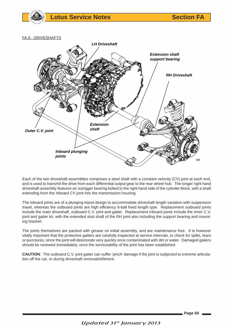
Page 60
Lotus Service Notes Section FA
FA.9 - DRIVESHAFTS
Each of the two driveshaft assemblies comprises a steel shaft with a constant velocity (CV) joint at each end, and is used to transmit the drive from each differential output gear to the rear wheel hub. The longer right hand driveshaft assembly features an outrigger bearing bolted to the right hand side of the cylinder block, with a shaft extending from the inboard CV joint into the transmission housing.
The inboard joints are of a plunging tripod design to accommodate driveshaft length variation with suspension travel, whereas the outboard joints are high efficiency 6-ball fixed length type. Replacement outboard joints include the main driveshaft, outboard C.V. joint and gaiter. Replacement inboard joints include the inner C.V. joint and gaiter kit, with the extended stub shaft of the RH joint also including the support bearing and mount-ing bracket.
The joints themselves are packed with grease on initial assembly, and are maintenance free. It is however vitally important that the protective gaiters are carefully inspected at service intervals, to check for splits, tears or punctures, since the joint will deteriorate very quickly once contaminated with dirt or water. Damaged gaiters should be renewed immediately, once the serviceability of the joint has been established.
cAutioN: The outboard C.V. joint gaiter can suffer 'pinch' damage if the joint is subjected to extreme articula-tion off the car, or during driveshaft removal/refitment.
LH Driveshaft
Outer C.V. joint
Inboard plungingjoints
Extension shaft
Extension shaftsupport bearing
RH Driveshaft
f170
Updated 31st January 2013

Page 61
Lotus Service Notes Section FA
Lh Driveshaft Assembly
rh Driveshaft Assembly
Clicking noises, torque reversal 'clonks', or shudder and vibration when accelerating are all possible symptoms of worn C.V. joints. It should not be possible to discern any free play in a joint by manual manipulation, but care must be taken not to confuse this with transmission backlash, which may be considerable. Any symptoms that could be due to worn driveshaft joint assemblies, should be investigated and rectified without delay, since safety considerations are always of paramount importance.
The inboard C.V. joint is equipped with a male splined spigot shaft which engages with the female splines of the differential output sun gear, with the LH shaft retained by a round section spring circlip on its end, and the RH shaft retained by the extension shaft support bearing. Each of the two transmission output oil seals runs on a machined shoulder on the C.V. joint spigot shaft, onto which is pressed a dust shield. The stub shaft of each outboard joint is splined into the wheel hub, and retained by a nut on the threaded end of the shaft.
Outboard joint Inboard plunging joint
f140
Extension shaft Inboard plunging joint Outboard joint
f141Extensionshaft bearing
Updated 31st January 2013
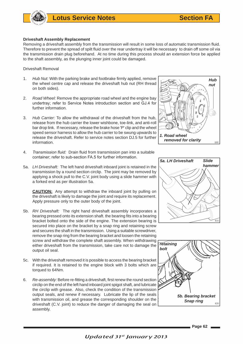
Page 62
Lotus Service Notes Section FA
Driveshaft Assembly replacementRemoving a driveshaft assembly from the transmission will result in some loss of automatic transmission fluid. Therefore to prevent the spread of spilt fluid over the rear undertray it will be necessary to drain off some oil via the transmission drain plug beforehand. At no time during this process should an extension force be applied to the shaft assembly, as the plunging inner joint could be damaged.
Driveshaft Removal
1. Hub Nut: With the parking brake and footbrake firmly applied, remove the wheel centre cap and release the driveshaft hub nut (RH thread on both sides).
2. Road Wheel: Remove the appropriate road wheel and the engine bay undertray; refer to Service Notes introduction section and GJ.4 for further information.
3. Hub Carrier: To allow the withdrawal of the driveshaft from the hub, release from the hub carrier the lower wishbone, toe-link, and anti-roll bar drop link. If necessary, release the brake hose 'P' clip and the wheel speed sensor harness to allow the hub carrier to be swung upwards to release the driveshaft. Refer to service notes section DJ.5 for further information.
4. Transmission fluid: Drain fluid from transmission pan into a suitable container; refer to sub-section FA.5 for further information.
5a. LH Driveshaft: The left hand driveshaft inboard joint is retained in the transmission by a round section circlip. The joint may be removed by applying a shock pull to the C.V. joint body using a slide hammer with a forked end as per illustration 5a.
cAutioN: Any attempt to withdraw the inboard joint by pulling on the driveshaft is likely to damage the joint and require its replacement. Apply pressure only to the outer body of the joint.
5b. RH Driveshaft: The right hand driveshaft assembly incorporates a bearing pressed onto its extension shaft. the bearing fits into a bearing bracket bolted onto the side of the engine. The extension bearing is secured into place on the bracket by a snap ring and retaining screw and secures the shaft in the transmission. Using a suitable screwdriver, remove the snap ring from the bearing bracket and loosen the retaining screw and withdraw the complete shaft assembly. When withdrawing either driveshaft from the transmission, take care not to damage the output oil seal.
5c. With the driveshaft removed it is possible to access the bearing bracket if required. It is retained to the engine block with 3 bolts which are torqued to 64Nm.
6. Re-assembly: Before re-fitting a driveshaft, first renew the round section circlip on the end of the left hand inboard joint spigot shaft, and lubricate the circlip with grease. Also, check the condition of the transmission output seals, and renew if necessary. Lubricate the lip of the seals with transmission oil, and grease the corresponding shoulder on the driveshaft (C.V. joint) to reduce the danger of damaging the seal on assembly.
Hub nut
1. Road wheel removed for clarity
j195
f172
Slidehammer
5a. LH Driveshaft
retaining bolt
5b. Bearing bracket Snap ring
f179
Updated 31st January 2013

Page 63
Lotus Service Notes Section FA
7. Driveshaft: Carefully insert the driveshaft into the transmission, with, on the left hand shaft, the two ends of the circlip positioned lowermost, and rotate the shaft if necessary to engage the splines. Press the inboard joint outer until a click indicates the engagement of the retaining circlip, if necessary tapping the joint outer body using a brass drift and hammer. Pull on the joint body to confirm its security. On the right hand shaft, fit a new snap ring on the extension shaft bearing and install a new securing screw (torque to 45 Nm).
8. Suspension: Fit the outer end of the shaft into the hub, and re-assemble the suspension links. Torque settings: Lower wishbone to hub carrier; 135 Nm. Toe-link to hub carrier; 135 Nm. ARB drop link;
38 Nm.
9. Hub Nut: Fit the hub nut and road wheel, apply the parking and footbrake, and tighten the hub nut to 300 Nm.
10. Lubricant: With the car on a level working surface, top up the transmission fluid; refer to sub section FA.5 for further information.
11. Wheel and Undertray: Refit the road wheel and undertray
Updated 31st January 2013

Page 64
Lotus Service Notes Section FA
FA.10 - TRANSMISSION REMOVAL/REPLACEMENT
The transmission may be separated from the engine only after removal of the complete powertrain from the car. See sub-section EJ.5 for main details but also refer to:
CD Lotus part number T000T1526F (Toyota ref. SC0264EA) Transmission > U660E AUTOMATIC TRANSAXLE > AUTOMATIC TRANSAXLE ASSEMBLY
Place a suitable container underneath the oil cooler sandwich plate area disconnect hoses from inlet and outlet pipes located at the side of the transmission; refer to sub-section FA.4 for further information.
Remove shift actuator and bracket to gain access to IPS harness connection located at the LH side of the transmission casing and unplug; refer to sub-section FA.3 for further information
Disconnect the harness multi-plug connector from the park/neutral switch and unbolt the harness at its ‘P’ clip connector.
IPSharnessconnector
f157
Park/neutral switch connector
'P' clip
f158