Lords View Draft Design Criteria...
27
Lords View Industrial Estate Architectural Design Criteria Administered by the Lords View Property Owners Association Reference No. 2009/H 16-04-2010
Transcript of Lords View Draft Design Criteria...

Lords View Industrial Estate
Architectural
Design Criteria Administered by the Lords View Property Owners Association
Reference No. 2009/H 16-04-2010

Page 2 of 27
CONTENTS
SECTION A – SITE DESIGN AND DEVELOPMENT CRITERIA ....................................................... 4
1. AIM OF THE DESIGN CRITERIA .................................................................................................................. 4
2. SITE DESCRIPTION..................................................................................................................................... 4
2.1. Location ................................................................................................................................ 4
2.2. Development Rights............................................................................................................. 4
2.3. Extent.................................................................................................................................... 4
2.4. Access ................................................................................................................................... 4
2.5. Topography .......................................................................................................................... 4
2.6. Geology................................................................................................................................. 4
3. DEVELOPER’S VISION ................................................................................................................................ 5
4. TOWNSHIP LAYOUT PRINCIPLES. .............................................................................................................. 6
5. STATUTARY DEVELOPMENT RIGHTS ......................................................................................................... 7
5.1. Land Use ............................................................................................................................... 7
5.2. Coverage............................................................................................................................... 7
5.3. F.A.R. (bulk factor) ............................................................................................................... 7
5.4. Height Restrictions ............................................................................................................... 7
5.5. Parking.................................................................................................................................. 7
5.6. Building Lines ....................................................................................................................... 7
5.7. Loading And Offloading ....................................................................................................... 8
5.8. Environmental Management Plan....................................................................................... 8
6. DESIGN CRITERIA FOR UTILIZATION OF SITES............................................................................................ 8
6.1. Site Development Categories .............................................................................................. 9
6.2. Boundary Classification...................................................................................................... 11
6.3. Site Planning Criteria.......................................................................................................... 14
7. SECURITY DESIGN CRITERIA .....................................................................................................................18
8. DEALING WITH PLATFORMS ....................................................................................................................18
9. DEALING WITH CONSOLIDATION .............................................................................................................19
9.1. Site Classification ............................................................................................................... 19
9.2. Boundary Conditions.......................................................................................................... 19
9.3. Platforms ............................................................................................................................ 19
SECTION B – ARCHITECTURAL DESIGN CRITERIA................................................................... 20
10. ARCHITECTURE ........................................................................................................................................20
10.1. Building Forms.................................................................................................................... 20
11. BUILDING HEIGHTS ..................................................................................................................................21
11.1. Office Buildings .................................................................................................................. 21
11.2. Industrial buildings and Warehouses ................................................................................ 21
12. MATERIALS ..............................................................................................................................................21
12.1. Roofs ................................................................................................................................... 21
12.2. Main Body .......................................................................................................................... 21
12.3. Plinths ................................................................................................................................. 21
12.4. Windows And Doors .......................................................................................................... 22

Page 3 of 27
12.5. Internal Roads And Parking Areas ..................................................................................... 22
13. PERIMETER ENCLOSURE...........................................................................................................................22
13.1. Visually Open Boundary Enclosures May Be One Of The Following: ............................... 22
13.2. Visually Closed Boundary Enclosures On Exposed Boundaries May Be One Of The
Following: ........................................................................................................................................... 22
13.3. Common Boundaries May Be One Of The Following: ...................................................... 22
14. EXTERNAL STRUCTURES...........................................................................................................................23
15. REFUSE ....................................................................................................................................................23
16. LANDSCAPING DESIGN CRITERIA .............................................................................................................23
17. CIVIL DESIGN DESIGN CRITERIA................................................................................................................23
17.1. Earthworks and Ground Stabilisation ............................................................................... 23
17.2. Stormwater Management ................................................................................................. 23
17.3. Roads and parking.............................................................................................................. 24
18. SIGNAGE..................................................................................................................................................24
18.1. Street Address .................................................................................................................... 24
18.2. Signage On Buildings.......................................................................................................... 25
19. SECURITY MEASURES...............................................................................................................................25
19.1. Site Perimeter Enclosure.................................................................................................... 25
19.2. Building Perimeter ............................................................................................................. 25
19.3. External Areas .................................................................................................................... 25
20. CONSTRUCTION .......................................................................................................................................26
20.1. Site Clearance And Stabilization........................................................................................ 26
20.2. Removal Of Rock ................................................................................................................ 26
The work shall be carried out in accordance with the Lords View Civil Design Criteria.................. 26
20.3. Earthworks ......................................................................................................................... 26
20.4. Site Establishment.............................................................................................................. 26
20.5. Access And Traffic Management ....................................................................................... 26
20.6. Noise And Disturbance ...................................................................................................... 26
21. DESIGN REVIEW PROCESS ........................................................................................................................26
22. SITE DEVELOPMENT PLANS (SDP) SUBMISSION REQUIREMENTS .............................................................26
22.1. Objects Of The SDP ............................................................................................................ 26
22.2. Requirements ..................................................................................................................... 26
22.3. Submission 26

Page 4 of 27
SECTION A – SITE DESIGN AND DEVELOPMENT CRITERIA
1. AIM OF THE DESIGN CRITERIA
The aim of the Design Criteria is to set out the objectives and the controls to manage physical development at
Lords View to achieve the desired overall functionality and estate character over time.
Compliance with the Design Criteria is a condition of subdivision. The Local Authority requires that building
plans must first be approved by the Lords View Property Owners Association (LVPOA) prior to the submission
of Scrutiny Plans to the Local Authority for the necessary building permits.
This document deals with the Site Design Criteria and the Architectural Design Criteria.
Collateral documents to be read with this document include the Conditions of Sale, Purchase Agreement,
Zoning Conditions, the Environmental Management Plan, the Civil Design Criteria, the Landscape Design
Criteria, and the Lords View Property Owners Association Constitution and Rules.
2. SITE DESCRIPTION
2.1. Location
Lords view is located mainly on the properties Klipfontein View Extension 5 and Chloorkop extensions 64, 66,
68 and 69. The site is located on the northern perimeter of Heartland on the highest land in the Metropolitan
area and enjoys magnificent views in all directions.
Accessibility is very high from all points in the northern Metropolitan area. The distance to the airport is within
13.2 km. The major north south arterial route to Pretoria passes 7 km to the west. The new Gautrain station is
situated approximately 7 km to the west. A large pool of skilled labour lives in the vicinity of the site.
2.2. Development Rights
The township has been rezoned for Industrial, commercial and office development. The General Plans have
been approved. An EIA has been concluded and an ROD has been issued with conditions of development.
2.3. Extent
There are approximately 63 sites within the currently approved estate. These may be developed in phases of
approximately 10 to 20 erven. The Design Criteria will apply to any other portions, accessible via the new
access road onto Allandale road, which may be incorporated into Lords View by the developer.
2.4. Access
A Traffic Impact Assessment has been conducted and a single multi-lane T-intersection has been approved
giving direct and exclusive access from Allandale Road. The existing east-west link provided by this route will
be supplemented by a new road from the south which will intersect with Allandale Road close to the site
2.5. Topography
The site is a former quarry that was mined to variable levels depending on the material quality. The excavation
left exposed shelves and outcrops of rock. Low areas in the north west quadrant are permanently flooded with
storm water run-off. Stockpiles of tailings are being removed and the topography will be reshaped to provide a
generally uniform shallow gradient on a phased basis. Exposed rock will be crushed on site and used to
stabilise embankments.
2.6. Geology

Page 5 of 27
The site is characterized by sheets of granite rock and weathered overlying granitic soils. Existing vegetation
stabilizes topsoil in areas less extensively mined. There is no underlying Dolomite.
3. DEVELOPER’S VISION
The rehabilitation of a quarry provides a unique opportunity to establish an industrial township based on
sustainable development principles. In the emerging world economy this is an important consideration for all
businesses engaged in trade and manufacturing. By adopting the appropriate strategies for developing the site
this goal can be achieved within the prevailing developed land price structure.
The following key sustainability elements have informed the development approach.
• Storm water attenuation on site in quarry dams
• Removal of alien vegetation for chipping and soil stabilization
• Introduction of wetland systems and swales for filtration of storm water run-off
• Greenbelt system established with indigenous flora and fauna.
• Removal of tailings for land fill stopping
• Development Design Criteria for sustainable construction and operations
• Electricity distribution will be handled by a private electricity distribution company.
The goal of the development Design Criteria is to ensure that businesses who establish at Lords View will
develop their properties to a consistent standard that sustains property values and enables ease of operation
for all users of the township. The Lords View Industrial Estate will offer the advantages of freehold title with
the benefits of a managed estate controlled by a Property Owners Association.

Page 6 of 27
Page 7 of 27
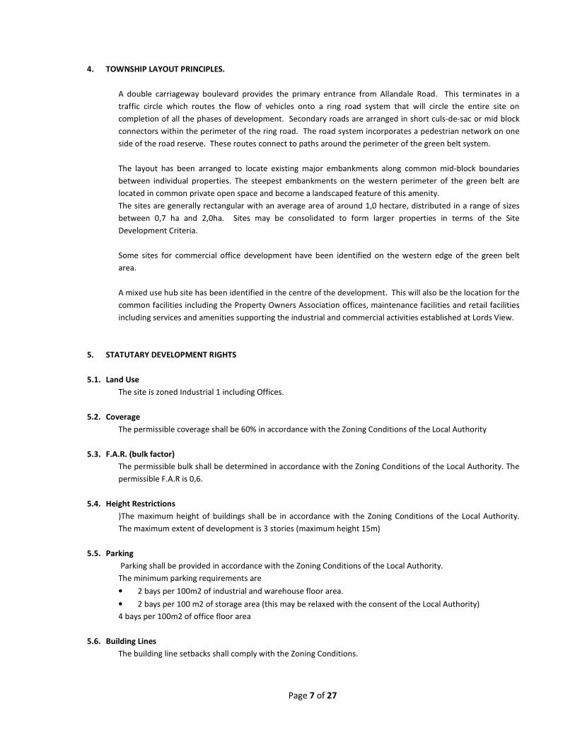
4. TOWNSHIP LAYOUT PRINCIPLES.
A double carriageway boulevard provides the primary entrance from Allandale Road. This terminates in a
traffic circle which routes the flow of vehicles onto a ring road system that will circle the entire site on
completion of all the phases of development. Secondary roads are arranged in short culs-de-sac or mid block
connectors within the perimeter of the ring road. The road system incorporates a pedestrian network on one
side of the road reserve. These routes connect to paths around the perimeter of the green belt system.
The layout has been arranged to locate existing major embankments along common mid-block boundaries
between individual properties. The steepest embankments on the western perimeter of the green belt are
located in common private open space and become a landscaped feature of this amenity.
The sites are generally rectangular with an average area of around 1,0 hectare, distributed in a range of sizes
between 0,7 ha and 2,0ha. Sites may be consolidated to form larger properties in terms of the Site
Development Criteria.
Some sites for commercial office development have been identified on the western edge of the green belt
area.
A mixed use hub site has been identified in the centre of the development. This will also be the location for the
common facilities including the Property Owners Association offices, maintenance facilities and retail facilities
including services and amenities supporting the industrial and commercial activities established at Lords View.
5. STATUTARY DEVELOPMENT RIGHTS
5.1. Land Use
The site is zoned Industrial 1 including Offices.
5.2. Coverage
The permissible coverage shall be 60% in accordance with the Zoning Conditions of the Local Authority
5.3. F.A.R. (bulk factor)
The permissible bulk shall be determined in accordance with the Zoning Conditions of the Local Authority. The
permissible F.A.R is 0,6.
5.4. Height Restrictions
)The maximum height of buildings shall be in accordance with the Zoning Conditions of the Local Authority.
The maximum extent of development is 3 stories (maximum height 15m)
5.5. Parking
Parking shall be provided in accordance with the Zoning Conditions of the Local Authority.
The minimum parking requirements are
• 2 bays per 100m2 of industrial and warehouse floor area.
• 2 bays per 100 m2 of storage area (this may be relaxed with the consent of the Local Authority)
4 bays per 100m2 of office floor area
5.6. Building Lines
The building line setbacks shall comply with the Zoning Conditions.

Page 8 of 27
The minimum statutory set back requirements are 5,0m meters on common boundaries and 6,0m from
internal street boundaries. Along the boundary with Allandale Road the minimum setback is 16,0m (which
may be relaxed to 10,0m subject to approval).
5.7. Loading And Offloading
All loading and offloading must be accommodated on individual sites. These activities are not permitted in the
common public spaces of streets and green belts.
5.8. Environmental Management Plan
Development of private sites must conform to the approved Environmental Management Plan and the
Ecological Management Plan
6. DESIGN CRITERIA FOR UTILIZATION OF SITES
The aim of these Design Criteria is to ensure the creation of positive enclosure of the public environment, to
gain the full benefit of the planned green space and to achieve a cohesive built image of the estate. The
controls aim to ensure a consistent approach to the internal arrangement and layout of sites.
The sites have been divided into four main categories which reflect the different neighbourhood requirements:
• High visibility sites – these are located closest to Allandale Road and require specific attention to visible
facades and boundary enclosures.
• Green edge sites – these are sites in the north western quadrant with boundaries directly onto the green
belt containing the storm water retention ponds and communal private open space.
• Typical internal sites – these sites are arranged in urban blocks fronting onto internal streets.
• Embankment sites – these sites incorporate a portion of a major level change embankment on their
boundaries.

Page 9 of 27

Page 10 of 27
6.1. Site Development Categories
6.1.1 Typical sites
All internal sites will have a primary street frontage. The aim is to locate the primary on-site parking and
landscaping adjacent to the designated primary street boundary with visually open fencing to create the sense
of a wide landscaped street environment.
Habitable space such as offices or labour intensive production areas must face towards the parking courts
and/or designated primary street frontages.
Service and loading yards should be set back out of direct site of the primary street frontages.
6.1.2 High visibility sites
The frontages of these sites towards Allandale Road and the entrance boulevard will be subject to specific
criteria to ensure that the entrance environment reflects the quality standards of the whole development. In
return the higher visibility presents the opportunity for bold signage and individual brand awareness. A
consistent scale of signage and façade design is required for these stands.
The same criteria applicable to typical sites will generally apply to High Visibility sites. In addition other street
boundaries with high visibility will be required to meet the same standards as the primary street approach
frontages.
The design of signage and building facades will be coordinated in terms of the specific criteria relating to the
orientation of these sites.
6.1.3 Green edge sites
The green belt and storm water dams are intended to be an amenity for all properties enjoying the Lords View
address. This area must be developed and maintained with a natural indigenous landscaped character.
Provision of paths and lighting by the developer will make this a pedestrian friendly environment with provision
for maintenance and security.
Sites directly adjacent to the green belt are required to treat the common boundary as a secondary public
frontage. Facades facing the green belt must be treated as for secondary street frontage conditions.
The layout has been adjusted to enable the front approaches to these sites to face towards the green belt. The
boundary treatments along the green must be visually open. Lighting across the boundary into the green belt
will be required. Provision for access to the green belt is required in specific locations.
6.1.4 Embankment sites
The major embankments are stabilized by the Developer. The subdivision has been arranged to ensure that
embankments on private property are located along the property boundaries. This area is included in the
F.A.R. calculation but cannot be built on. Maintenance of the embankment is the responsibility of the
individual Property Owner. Structural changes to the embankment may not be made without the consent of
the LVPOA and must be certified by a suitably qualified Engineer.

Page 11 of 27

Page 12 of 27
6.2. Boundary Classification
In order to establish a consistent common environment for the township the boundaries of all properties have
been classified into three categories. These categories are the basis for the site planning controls for each
individual property. The categories are:
• Primary Boundaries
• Secondary Boundaries
• Internal Boundaries
6.2.1 Primary boundaries
These generally define the streetscape or green belt and provide the approach frontage to each property. The
control of individual site layouts along these boundaries is intended to ensure a consistent public environment
lined by office facades, main entrances and parking courts, suitably landscaped and maintained.
Main facade treatment
• The main facades of habitable buildings (offices or labour intensive production areas) must face this
boundary.
• The main parking court must be situated adjacent to this boundary in a parallel layout or at right angles
with the boundary.
• A planting strip is to be provided along the full length of these boundaries (interrupted for access
driveways), extending into the property to a minimum distance of 2,0 meters from the front boundary.
• Main entrances and primary signage must face this boundary.
• Boundary enclosure and entrance gates along these boundaries must be visually open and conform to the
specifications permitted in the Design Criteria. Common side boundary enclosure shall match the front
enclosure design and be visually open to a distance back from these boundaries so as to line up with the
main façade or screen walls.
• No service yards and loading areas may be located facing these boundaries without visually closed screen
walls positioned on or behind the street building line
• The minimum set-back for buildings and solid boundary and screen walling parallel to these boundaries
shall be 6,0 meters.
• The LVPOA may, upon receipt of a written application or the submission of a site development plan, allow
the erection of a building in the building restriction area in the case of a corner erf, or if, as a result of the
topography of the property or the adjacent land or of the propinquity of buildings already erected on the
building restriction area or if adherence to the building line requirements would unreasonably hamper the
development of the property.
• Refuse rooms at the street boundary shall be screened as specified in the Design Criteria.

Page 13 of 27
Site Boundaries & Circulation
6.2.2 Secondary boundaries
These boundaries also define the streetscape but are not designated as the main approach frontage to the
individual properties. This typically occurs on a corner stand or where a property is situated between two
parallel street boundaries. These boundaries front common space and need to be finished to the same
standard as the Primary Boundaries. There is less effect on the internal planning of sites.
• Facades and signage facing these boundaries must be finished and maintained to the same standard as
those facing the Primary Boundaries.
• No service yards and loading areas may be located facing these boundaries without visually closed screen
walls positioned on or behind the building line.
• The minimum set-back for buildings and solid boundary and screen walling parallel to these boundaries
shall be 6,0 meters.
• Boundary enclosure along these boundaries may be visually closed provided the design conforms to the
specifications permitted in the Design Criteria.

Page 14 of 27
6.2.3 Internal boundaries
All properties are to be fully enclosed with suitable security walling.
• Common boundaries behind the set back lines associated with Primary and Secondary Boundaries must
be enclosed with solid walling for security and site stabilization to a minimum height of 2,0 meters in
accordance with the specifications in the Design Criteria.
• Buildings are to be set back a minimum distance of 5,0 meters from all internal boundaries.
• Boundary enclosure cutting across steep embankments must be designed by a qualified Engineer to
maintain the structural integrity of the embankment stabilisation.
6.3. Site Planning Criteria
Further to the conditions determined by the Boundary Enclosure Categories the following requirements apply
to the layout of individual sites:
6.3.1 Access and circulation
• A single two-way entrance driveway will be permitted across the Primary Boundary.
• Two one-way entrance driveways will be permitted across the Primary Boundary in the case of a one way
on-site circulation system.
• Gates may be set flush with the boundary provided that any gate shall be set back a minimum of 12,0
meters from the kerb line of the public access road.
• No entrance driveway will be permitted within 12,0 meters of an intersection.
• Internal roads and parking may extend over the building set back lines to any boundary.
Single entry – one-way Single entry – two-way Two one-way driveways
Entrance with swing gates, booms & gatehouse Entrance with sliding gate
Site Access and Circulation

Page 15 of 27
6.3.2 Parking
• Staff and visitors parking must be located in the main parking courtyards adjoining the Primary
Boundaries, generally in the configuration indicated and preferably on the lower side of the site, to allow
for permeable paving (described below).
• Additional parking may be located elsewhere on the site, along the side or rear boundaries.
• A maximum of one level of parking may be provided under buildings at ground level. Structured parking
facing the Primary Boundary shall be screened with façade walls in keeping with the character of the
adjoining accommodation.
• Basement parking may be provided at the discretion of the property owner.
Parking
6.3.3 Loading areas, service yards, and external plant installations.
• All routes and maneuvering spaces associated with loading areas for service vehicles must be located on
individual sites in accordance with these Design Criteria.
• These may be located along the sides or rear of the buildings
• They may not be located in front of the office facades.
• They may not be visible across the Primary or Secondary Boundaries.
• Loading yards facing Primary Boundaries must be visually screened as specified in the Design Criteria and
may not exceed 1/3 of the length of the Primary Boundary on any property.

Page 16 of 27
6.3.4 Refuse Rooms
• These shall be located within the property on the street boundary.
• They should be integrated with other structures on the street boundary including the entrance gateway or
electrical substation.
• Access from the street shall conform with the requirements of the Local Authority

Page 17 of 27
6.3.5 Electrical Sub-stations
These shall be located within the property at the intersection of a common side boundary and the street
boundary, generally not at the lowest point along the boundary to avoid stormwater run-off .
The siting, access, specification and reticulation of electrical substations shall conform to the Electrical Design
Criteria.
The enclosure and access gates for electrical substations shall be designed to match the street boundary
enclosure.
6.3.6 Building types
• Office buildings must be located adjacent to the main parking courtyard, street or green belt.
• Warehouse and industrial structures must be set back behind the main office facades.

Page 18 of 27
7. SECURITY DESIGN CRITERIA
All individual properties shall provide their own security. Perimeter security measures shall comply with the
Site Design Criteria.
• Physical security measures (e.g. spikes, barbs, electrified fencing) on Primary, Secondary and Connecting
boundaries must be integrated into the design of the perimeter enclosure to standards acceptable to the
LVPOA.
• Razor wire may not be introduced in visible locations on boundaries or structures.
• Security flood lighting must be mounted on buildings or external walling or fencing.
• Area lighting of parking areas and circulation routes may be pole mounted luminaires not exceeding 8,0
meters in height.
• Gatehouses must be positioned inside the boundary and integrated with the design of the boundary
enclosure. No boom may be located closer than 12,0 meters to the back of kerb line of the public access
road at the point of entry.
8. DEALING WITH PLATFORMS
The site is graded to shallow gradients over the greater portion of each phase by the Developer. Significant
changes in level have been arranged along specific boundaries. Certain streets also follow a steeper gradient
and the classification of boundaries and access has been arranged to ensure that access to properties is subject
to the least changes in level.
To reduce cut and fill between neighbouring properties and with the street, the following criteria must be
observed when determining finished levels on sites:
• Cut and fill must balance on each site. If this is not possible, substantiating information by a suitably
qualified Engineer must be submitted in order to obtain the special consent of the LVPOA for the removal
of material from an individual site.
• Large level changes must be avoided where it is possible to introduce several platforms between the
various buildings and usage areas on the site.
• In the case of level changes at the property boundary, embankments must be set back 1,0 meter from the
boundary line and not impact on neighouring properties. The design must be submitted for LVPOA
approval by a suitably qualified Engineer.
• Internal gradients must be kept shallow and avoid concentrating run-off of stormwater across any
boundary.

Page 19 of 27
9. DEALING WITH CONSOLIDATION
The intent of the Site Design Criteria,, to maintain a consistent standard and layout approach to the common
environment at Lords View, shall continue to apply when sites are consolidated, irrespective of the site
configuration resulting from the consolidation.
9.1. Site Classification
• The classification zones and the intentions and controls applicable to individual sites shall remain in place
and apply to the same portion of any consolidated group of sites.
9.2. Boundary Conditions
• The controls and site planning criteria associated with the demarcated Boundary Conditions shall remain
in place and apply to the same portions of any consolidated group of sites unless otherwise agreed with
the LVPOA due to the configuration of buildings and operations on the consolidated site.
• However the controls applicable to Internal Boundaries as defined in the Design Criteria, and specifically
in the case of building set-backs, shall not remain in force for previous common boundaries of sites
situated within the perimeter of a subsequently consolidated site.
9.3. Platforms
• The same criteria relating to platforming on individual sites shall apply to consolidated sites.

Page 20 of 27
SECTION B – ARCHITECTURAL DESIGN CRITERIA
10. ARCHITECTURE
10.1. Building Forms
The design of the buildings must be contemporary and minimalist, and respond to the climate using sustainable
design principles to reduce energy consumption in manufacture and throughout the life cycle of the building.
The following elements will be deployed to achieve this:
• Habitable spaces to be constructed in masonry. Plastered or face brick finishes may be used in
accordance with the Design Criteria.
• Roofs to habitable spaces are to be insulated.
• All roofs and metal wall cladding must be finished with light grey or white roofing material to reflect heat
and maintain a consistent character to Lords View.
• Windows to be protected from direct sunlight by canopies or shutters.
• Large glazed areas must use low heat transmission laminated glass. Highly reflective glass will not be
permitted.
• Ventilation and heat extraction through roofs is permitted. Low profile cowls that are integrated with the
roof must be used.
10.1.1 Office buildings and workshops
• The main body of the office building should be masonry wall architecture with punched window openings
with deep reveals.
• Where a curtain wall or floor to ceiling glazing is introduced into the façade, this should be recessed
deeply so no direct sunlight falls on this Façade between 10h00 and 14h00.
• A maximum of 50% of the façade will be allowed to be glazed in this manner.
• The entrance to the office building must face the parking court and be designed as a focal element of the
property
• Where the office building comprises a separate footprint, the roof must be separated from the roof of the
main industrial warehouse structure behind. In this case the office roof must be mono-pitched or low
pitched with an eaves overhang at the façade perimeter.

Page 21 of 27
• The main entrance must be treated as a feature on the office façade, providing shelter over the main
door.
10.1.2 Industrial and warehouse buildings
• The industrial building should be screened by the administrative building. The two components may be
joined or integrated provided that the Site Design Criteria are adhered to.
• The main body of the industrial building can be a sheet metal façade, however this should be articulated
by revealing structure or developing rhythm in the façade. Metal sheet cladding of facades facing Primary
Boundaries should not extend below the first floor level which should be expressed as a solid base
masonry structure finished to match the office building.
• Loading bays should be protected by overhanging canopies designed to tie in with the roof construction
and finish.
11. BUILDING HEIGHTS
The statutory height limits will be applied subject to the following additional controls.
11.1. Office Buildings
• Where offices are the secondary use on a site accommodating a larger industrial or warehouse building,
the height of the office building roof must be lower than the eaves height of the industrial or warehouse
buildings on the site.
11.2. Industrial buildings and Warehouses
• The maximum eaves height of an industrial or warehouse building shall not exceed 13,5 meters above
average finished ground level measured around the full perimeter of the industrial or warehouse building
footprint.
12. MATERIALS
12.1. Roofs
• Roofs may be profiled sheet metal finished in factory applied colours (white or light grey). Flat roofs may
be concrete or malthoid on timber surfaced with stone chip over suitable black or silver waterproofing.
• Roof profiles can accommodate various forms of monitor roof lights within the permitted height limits.
• Eaves and barge details must be crisp and angular and must match the roof colour. Bullnose profiles will
not be permitted.
• Exposed rainwater gutters and downpipes must match the roof colour.
12.2. Main Body
• Metal profiled cladding in factory applied colours to match the roof is permitted on warehouse and
industrial buildings. Habitable offices and workshops must be finished in white painted plaster or natural
face brick.
• Face bricks must match the Corobrick Bergendal Satin Light face brick.
• All suspended concrete slabs to be constructed using Echo Prestress hollow core slabs or similar approved
system.
12.3. Plinths
• These may be painted plaster in darker earth colours or the face brick specified above.

Page 22 of 27
12.4. Windows And Doors
• External windows, doors and glazed curtain walling frames shall be in steel or aluminium, finished in
black, white, light grey or natural anodized alumnium.
12.5. Internal Roads And Parking Areas
• The parking court must be surfaced with grey concrete pavers or with clay brick pavers to match the
Corobrick Cedarberg paver. Porous paving must be designed to provide stormwater filtration on site
before discharging into the common stomwater drainage system.
• Internal roads must be surfaced in pavers to match the parking courts. Roads bearing heavy traffic may
be surfaced in premix or concrete. Turning areas for heavy vehicles and loading yards may be constructed
with concrete surface beds.
• Only light metal framed white or grey fabric shade structures will be permitted over car embayments in
the parking.
13. PERIMETER ENCLOSURE
13.1. Visually Open Boundary Enclosures May Be One Of The Following:
• Vertical metal palisade fencing with steel columns not exceeding 2,4 meters in height, painted in black or
dark green.
• Vertical metal palisade fencing with masonry columns with a plastered and paint, or face brick finish to
match the main building façade not exceeding 2,4m in height.
13.2. Visually Closed Boundary Enclosures On Exposed Boundaries May Be One Of The Following:
• Masonry walls with piers on the internal face with plaster and paint, or face brick finish, to match the
main building façade not exceeding 2,4 meters in height.
• Echo concrete modular panel walling to match the park boundary, not exceeding 2,4m in height.
13.3. Common Boundaries May Be One Of The Following:
• Masonry walls with piers on the internal face with plaster and paint, or face brick finish, to match the
main building façade not exceeding 2,4 meters in height.
• Echo concrete modular panel walling to match the park boundary, not exceeding 2,4m in height.

Page 23 of 27
14. EXTERNAL STRUCTURES
All external buildings and light structures and shall be masonry structures to match the character and standard
of the main buildings on the site.
15. REFUSE
Refuse and waste material on site shall be housed in structures to the statutory standards.
16. LANDSCAPING DESIGN CRITERIA
Each individual site is required to add to the environmental quality of Lords View by contributing to the green
space and landscaping of the township. Plants must be selected from the plant list approved by the LVPOA.
Landscaped areas must be irrigated to the satisfaction of the LVPOA. Private landscaping must conform to the
approved Environmental Management Plan for Lords View.
The landscape design and implementation must conform to the Lords View Landscape Design Criteria.
16.1. Soft Planting
Where planting has already occurred across the area where access is to be taken, care must be taken not to
disturb more of the planting than is absolutely necessary. All planting adjoining the access ways is to be reinstated
if disturbed.
16.2. Pedestrian Paving
Where pedestrian paving has been installed or where it is intended to install pedestrian paving, coordination with
the landscape architect is essential so as to ensure that the aesthetic of the sidewalk is not deteriorated.
17. CIVIL DESIGN CRITERIA
17.1. Earthworks and Ground Stabilisation
The design and implementation of earthworks, embankments and retaining structures must conform to the
Lords View Civil Design Criteria.
17.2. Essential services
Service connection points and service kiosks have been offset from the boundary so as not to interfere with the
positioning of the ingress and egress from individual erven. Care must be taken to protect service connections
and kiosks and should it be necessary to have them moved, arrangements must be made with the Estate
Management for this work to be done.
Each individual property is connected to the water borne sewerage system serving the Development. The
position and depth of each connection is shown on the Record Drawings available from the Estate
Management.
Each individual property is provided with a standard 110mm water connection. Where a larger connection is
required, arrangements must be made with the Estate Management and the necessary application and fees
paid for such connections.

Page 24 of 27
17.3. Stormwater Management
The stormwater design and implementation must conform to the approved Lords View Environmental
Management Plan for Private Sites and the Lords View Civil Design Criteria.
The normal storm water system which connects to kerb inlets on the road kerb line is to intercept 1:5 and 1:25
year storm occurrences and convey them in an underground pipe network to large attenuation facilities within
the Development.
Clean storm water attenuation
It is a requirement that each property has porous paving or stormwater attenuation positioned under some
part of the paving on the site. The position of the connection point for the discharge of each property is
indicated on the Record Drawings available from Estate Management.
17.4. Roads and parking
The design and implementation of trafficable areas must conform to the Lords View Civil Design Criteria
Access through a median
Where access through the constructed median is approved b the Design Review Committee, after specific
written request and motivation, the Estate Management will make the necessary arrangements for the
opening to be constructed at the applicant’s expense.
Where no-mountable kerbs occur.
A bell mouth with kerb radii of not less than 5m needs to be constructed and the paving of the relevant
driveway needs to be taken right up to the edge of the surfacing of the road.
Where mountable kerbs occur.
The kerb is to remain in place and the paving of the relevant access is to be taken up to the back of the kerb.
18. SIGNAGE
• The objective of the signage Design Criteria is to allow individual corporate brand establishment in a
consistent manner throughout Lords View.
• Private brand signage may only be located on buildings on private properties and will not be provided in
the public environment.
• Directional signage based on street addresses is provided by the Developer and LVPOA as part of the
approved street furniture system.
• No third party advertising will be permitted at Lords View.
18.1. Street Address
• Each site shall be identified by a sign showing the street number at the entrance gate.
• This sign shall be mounted for good visibility on the boundary enclosure or gate post and conform to the
graphic standard for Lords View as defined by the LVPOA.
• Address signs shall use 200 mm high black lettering in Helvetica/Arial font, on a white background.

Page 25 of 27
18.2. Signage On Buildings
• Signage on buildings must be fully integrated with an architectural feature on the façade and may not
comprise more than 10% of any façade.
• The brand primary signage must face the Primary Boundary and reinforce the approach to the entrance.
• Signs may be located on any vertical elevation of the building, but not flat or sloping roof surfaces.
• Other than the street address sign, brand signage is not permitted on boundary enclosures.
• Painted signs directly on roof and wall materials are not permitted.
19. SECURITY MEASURES
Private security measures must be visually unobtrusive and environmentally and functionally compatible with
the private and common uses at Lords View. Details of physical security installations must be submitted to the
PVPOA for approval.
19.1. Site Perimeter Enclosure
All security measures at the boundary must conform to the specifications set out in the Design Criteria.
19.2. Building Perimeter
Security measures on the buildings must be fully integrated with the architectural design of the facades.
Burglar bars, must be integrated with small pane windows and frames set within wall reveals. Hinged or sliding
shutters may be mounted on facades. Security gates must be mounted within door frames set into wall reveals.
Roller mechanisms must be mounted behind or within the façade opening.
19.3. External Areas
Security measures on sites for human safety and to protect industrial operations shall conform to the
specifications in the Design Criteria for external walling, enclosure, security booths and lighting. External
security measures may not cause disturbance or risk to any neighbouring properties or the common
environment.

Page 26 of 27
20. CONSTRUCTION
20.1. Site Clearance And Stabilization
The work shall be carried out in accordance with the Lords View Civil Design Criteria.
20.2. Removal Of Rock
The work shall be carried out in accordance with the Lords View Civil Design Criteria
20.3. Earthworks
The work shall be carried out in accordance with the Lords View Civil Design Criteria
20.4. Site Establishment
Any builder’s site establishment camp and stockpile shall be contained on the individual property unless prior
written consent has been granted by the Property Owners Association to an alternative location.
20.5. Access And Traffic Management
The Property Owners Association may restrict access routes and impose other conditions governing the
movement of construction traffic from time to time to ensure the minimum disturbance and wear and tear to
the established township infrastructure and property owners.
20.6. Noise And Disturbance
The Lords View Property Owners Association may introduce conditions to control the noise and disturbance
resulting from the development of an individual property to ensure the minimum disturbance to the
established township and property owners.
21. DESIGN REVIEW PROCESS
The LVPOA will adjudicate each building plan submission strictly in accordance with these Design Criteria and
any other conditions that the LVPOA may be empowered to impose on the development of properties at Lords
View. The ultimate approving authority remains the relevant Local Authorities with jurisdiction over this area.
22. SITE DEVELOPMENT PLANS (SDP) SUBMISSION REQUIREMENTS
22.1. Objects Of The SDP
The SDP submission must patently address and illustrate in drawings and specification, all the conditions and
requirements of these Design Criteria, all Statutory conditions applicable to the site, the National Building
Regulations, the requirements of the Factories Act and other applicable legislation and any other conditions
that he the LVPOA may be empowered to impose.
22.2. Requirements
22.2..1. Site plan
The Site plan shall show the site boundaries, applicable set back lines, site levels, outline of all built structures,
external works including roads, parking, boundary treatments and external structures. Drawing shall be
prepared to a minimum scale of 1:20
22.2..2. Plans, sections and elevations and schedules

Page 27 of 27
These shall be prepared to a minimum scale of 1:100. Plans and sections must show all finished floor levels in
relation natural ground levels at the facades and at the site boundaries. Details of carriageway crossing levels
between street levels shall be shown. Properties abutting the green belt shall also show finished levels on site
in relation to the 50 and 100 year flood lines within the green belt. The eaves height of structures on
neighbouring properties shall be shown. All retaining walls shall be indicated with supporting information on
levels.
Elevations must indicate the finishes to be used.
Signage positions on facades must be indicated and the graphic layout and construction details of the signs are
to be submitted for the approval of the LVPOA.
22.2..3. Supporting illustrations
Submissions must include images of the adjoin properties and neighbouring streetscape. Illustrative renderings
are optional but where provided should show the site development in context with the surroundings.
22.2..4. Any necessary services and traffic plans
Civil Design information prepared by a qualified Engineer shall be submitted to the LVPOA in accordance with
the Civil Design Criteria.
22.2..5. Landscape plan
A landscape plan shall be submitted to the LVPOA, in accordance with the Landscape Design Criteria, for
approval.
22.2..6. Stormwater management plan
A Stormwater Management Plan prepared by a suitably qualified Engineer shall be submitted to the LVPOA, in
accordance with the Civil Design Criteria, for approval.
22.2..7. Electrical demand requirements
An Electrical Report prepared by a suitably qualified Engineer shall be submitted to the LVPOA, in accordance
with the Electrical Design Criteria, for approval.
22.2..8. Specialists
Any process deemed to have a high level of environmental impact or disturbance affecting neighbouring
property owners may require specialist input and the implementation of special development conditions at the
discretion of the Property Owners Association, within reasonable parameters.
Any supporting documentation relating to the accommodation of unique processes on individual sites must be
included in the submission.
22.3. Submission
22.3..1. Approval by the Lords View Property Owners Association
Applications are to be submitted directly to the designated office of the LVPOA.
22.3..2. Local Authority plan approval
Once the LVPOA has approved the plans for an individual site the Owner may forthwith submit the approved
plans to the relevant Local Authority for building plan approval.