Loop-O9550 SDH/SONET IMAP - dcbnet.com SDH/SONET IMAP Features y 5U height, full front access (ETSI)...
19
1 Preliminary Loop-O9550 SDH/SONET IMAP Features 5U height, full front access (ETSI) shelf ADM, TM, and cross-connect Single STM-1/4 (OC-3/12) optical ring uplinks · Up to four STM-1/4 (OC-3/12) aggregate lines that are software configurable · Non-blocking N x 64 Kbps for 252 E1 or 336 T1 for data and voice channel transmission for uplink site · Non-blocking N x 64 Kbps for maximum 64 E1 or 52 T1 for data and voice channel transmission for tributary site Tributary modules (see Table 1 next page) Power Modules: · DC Module: (-48Vdc, -24Vdc, -125Vdc) · Dual Power: (1+1) Protection SSM and CLK hold over function (SDH/SONET and E1/T1) Controller protection: · MSP (1+1) or SNCP for single controllers · MSP (1+1) and SNCP for dual controllers Per chassis supports single SDH or SONET Ring only A-law to μ-law conversion Alarm in/out, clock in/out Compatible to a SNMP based GUI network management system and supported by LoopView and Loop iNMS SSH V2 SNMP V1 and V3 RoHS compliance The Loop-O9550 SDH/SONET IMAP (Integrated Multi-Service Access Platform) is an economical STM-1/4 (OC-3/12) access multiplexer. It is designed to combine digital access interfaces, including TDM, IP, and voice interfaces into STM-1/4 (OC-3/12) optical lines for convenient transport and switching. This unit is a full cross-connect; one or more of the WAN ports can be used as a Drop & Insert function with fractional E1/T1 lines, which can be muxed into a full E1/T1 line. The O9550 provides two optical line signals at STM-1 (OC-3) or STM-4 (OC-12) with protection schemes including MSP (1+1) and SNCP protection in both ring and linear network topologies. Redundancy is available in dual CPU controllers and power supply options, making the O9550 an excellent fit for critical applications. The chassis does not need or contain fan cooling, though an external fan tray is available. The O9550 supports local control and diagnostics by using by using a VT-100 terminal connected to the console port. The O9550 also supports Ethernet, Telnet, SSH and SNMP so that it can also be controlled and diagnosed from remote locations. An in-band management channel with GUI is available. LED indicators for all plug-in cards are also available.
Transcript of Loop-O9550 SDH/SONET IMAP - dcbnet.com SDH/SONET IMAP Features y 5U height, full front access (ETSI)...

1
Preliminary
Loop-O9550 SDH/SONET IMAP
Features 5U height, full front access (ETSI) shelf ADM, TM, and cross-connect Single STM-1/4 (OC-3/12) optical ring uplinks · Up to four STM-1/4 (OC-3/12)
aggregate lines that are software configurable
· Non-blocking N x 64 Kbps for 252 E1 or 336 T1 for data and voice channel transmission for uplink site
· Non-blocking N x 64 Kbps for maximum 64 E1 or 52 T1 for data and voice channel transmission for tributary site
Tributary modules (see Table 1 next page) Power Modules: · DC Module: (-48Vdc, -24Vdc, -125Vdc)· Dual Power: (1+1) Protection
SSM and CLK hold over function (SDH/SONET and E1/T1)
Controller protection: · MSP (1+1) or SNCP for single
controllers · MSP (1+1) and SNCP for dual
controllers Per chassis supports single SDH or SONET
Ring only A-law to µ-law conversion Alarm in/out, clock in/out Compatible to a SNMP based GUI network
management system and supported by LoopView and Loop iNMS
SSH V2 SNMP V1 and V3 RoHS compliance
The Loop-O9550 SDH/SONET IMAP (Integrated Multi-Service Access Platform) is an economical STM-1/4 (OC-3/12) access multiplexer. It is designed to combine digital access interfaces, including TDM, IP, and voice interfaces into STM-1/4 (OC-3/12) optical lines for convenient transport and switching. This unit is a full cross-connect; one or more of the WAN ports can be used as a Drop & Insert function with fractional E1/T1 lines, which can be muxed into a full E1/T1 line. The O9550 provides two optical line signals at STM-1 (OC-3) or STM-4 (OC-12) with protection schemes including MSP (1+1) and SNCP protection in both ring and linear network topologies. Redundancy is available in dual CPU controllers and power supply options, making the O9550 an excellent fit for critical applications. The chassis does not need or contain fan cooling, though an external fan tray is available. The O9550 supports local control and diagnostics by using by using a VT-100 terminal connected to the console port. The O9550 also supports Ethernet, Telnet, SSH and SNMP so that it can also be controlled and diagnosed from remote locations. An in-band management channel with GUI is available. LED indicators for all plug-in cards are also available.

2
Loop-O9550 cards: The Mini-Slot Cards plug into the Mini-Slots of the O9550. The Single-Slot Cards plug into single slots, and the Dual-Slot Cards plugs into two adjacent single slots. Plug-in cards O9550 Mini-Slot 1-channel E1 (Single E1 interface) √
1-channel T1 (Single T1 interface) √ Mini Quad E1 (Four E1 interfaces) √ Fiber optical interface √
2-LAN port.64 WAN port Router-A √ 3-channel E1 √ 4-channel E1 √ 4-channel T1 √ 2-channel G.SHDSL (2 pairs) w/o line power √ 4-channel G.SHDSL (1 pair) w/o line power √ 8-channel G.703 card at 64 Kbps data rate √ 8-channel Dry Contact I/O type A/B √ 8-channel 2W/4W E&M √ 12-channel FXS √ 12-channel FXO √ 12-channel Magneto √ Conference card √ 1-channel low speed optical (C37.94) √ 4-channel low speed optical (C37.94) √ 8-channel RS232 with X.50 subrate √ 8-LAN-port/ 64-WAN-port Router-B √ 4-channel TDMoE √ 8-channel Data Bridge √
Single-Slot
1FOMA √ 24-channel FXS √ 24-channel FXO √ 6-channel X.21/V.11 √ 6-channel V.35 √ 6-channel V.36 √
Dual-Slot
6-channel EIA530/RS449 card √ Note: √ = Supported × = Not supported
* Future Option

3
Ordering Information Note: RoHS compliant units are identified by the letter G appearing immediately at the end of ordering code.
Model
(RoHS compliant) Description Note
Main Unit Loop-O9550-R-CGA-G 5U Rack chassis unit without CPU, power and plug-in
cards, applicable to use with MSP (1+1), SNCP ring With O9550-CGA
CPU Loop-O9550-R-CC4A-G CPU card with cross-connect unit and two STM-1/4
(OC-3/12) interfaces without SFP (mini-GBIC) optical modules (order two for redundancy) Single controller card with MSP 1+1or SNCP ring Dual controller cards with SNCP ring and MSP 1+1
One required for each chassis. Order two for redundancy. For opt option, please refer to the SFP optical brochure for detail information
Mini Plug-in Module (Select 1 to 4 cards from list below) Loop-O9550-R-E75-G 1-channel of E1plug-in card w/ 75 ohm Loop-O9550-R-E120-G 1-channel of E1 plug-in card w/ 120 ohm Loop-O9550-R-T1-G 1-channel T1 plug-in card Loop-O9550-R-M4E75-G Mini Quad E1 plug-in card
with 75 ohm Includes a three meter conversion cable (Loop-ACC-CAB-DB25M- 300-8BNCM)
Loop-O9550-R-M4E120-G Mini Quad E1 plug-in card with 120 ohm
Includes a three meter conversion cable (Loop-ACC-CAB-DB25M- 300-4RJ48M)
Loop-O9550-R-RTA-G 2-LAN ports/64 WAN port router/bridge plug-in card Loop-O9550-R-FOM-opt-G Fiber Optical plug-in card
For opt option, please refer to the table below for detail information
Single Slot Plug-in Module Loop-O9550-R-TDMoE-PPM-G
TDMoE card with 2 GbE combo interfaces and 2 Ethernet interfaces (10/100/1000BaseT) plug-in module Support G.823 Traffic
Loop-O9550-R-TDMoE-PPB-G
TDMoE card with 2 GbE combo interfaces and 2 Ethernet interfaces (10/100/1000BaseT) plug-in module Support G.823 Synchronization
Loop-O9550-R-4E1-cc-G 4-channel E1 plug-in card For cc option, please refer to the table below for detail information
Loop-O9550-R-4T1-G 4-channel T1 plug-in card Loop-O9550-R-2GH-G 2-channel G.SHDSL plug-in card (2 pair) Loop-O9550-R-4GH-G 4-channel G.SHDSL plug-in card (1 pair) Loop-O9550-R-8CD-G 8-channel G.703 plug-in card at 64 Kbps data rate Loop-O9550-R-8DC-G 8-channel dry contact plug-in card with maximum voltage
100 Vdc or 250 Vac
Loop-O9550-R-8DCB-G 8-channel dry contact type B plug-in card with maximum voltage 220 Vdc or 250 Vac
Loop-O9550-R-1C37-G 1- channel C37.94 plug-in card Loop-O9550-R-4C37-G 4- channel C37.94 plug-in card Loop-O9550-R-8RS232-RJ-G 8-port RS232 plug-in card with X.50 subrate multiplexing
scheme and X.54 encoding, with 8 RJ48 connectors for 8 RS232 Async ports
Loop-O9550-R-8RS232-DB-G 8-port RS232 plug-in card with X.50 subrate multiplexing scheme and X.54 encoding, with 2 RJ48 connectors and 2 DB44 connectors for Async and Sync ports
Two conversion cables are included (DB44 connector to two DB25 and one DB9 connector; (Loop-ACC-CAB-DB44M-100- 2DB25F-1DB09F-DB).
Loop-O9550-R-8DBRA-RJ-G 8-channel data bridge plug-in card, with 8 RJ48 connectors for 8 data bridge Async ports
Loop-O9550-R-8DBRA-DB-G 8-channel data bridge plug-in card, with 2 RJ48 connectors and 2DB44 connectors for 8 data bridge Async ports
Two conversion cables are included (DB44 connector to two DB25 and one DB9 connector; (Loop-ACC-CAB-DB44M-100- 2DB25F-1DB09F-DB).
Loop-O9550-R-RTB-G 8-LAN ports/64 WAN ports router/bridge plug-in card

4
Loop-O9550-R-1FOMA-opt-G 1FOMA Fiber Optical Interface with 1x9 optical port For opt option, please refer to the table below for detail information
Loop-O9550-R-CONF-G Conference plug-in card with two RS232 data ports, two FXS ports and two E&M ports
Loop-O9550-R-8EM-x-G 8-channel 2W/4W E&M plug-in card with 8 RJ45
For x option, please refer to the table below for detail information
Loop-O9550-R-12FXS-sn-pt-G
12-channel FXS plug-in card with 600/900 Impedance, Battery Reverse, Loop Start and PLAR. Without Ground Start and Metering Pulse. Used with 12 RJ11.
Loop-O9550-R-12FXS-P-sn-pt-G
12-channel FXS plug-in card with 600/900 Impedance, Battery Reverse, Loop Start, PLAR and [PLAR bit programmable]. Without Ground Start and Metering Pulse.Used with 12 RJ11.
Loop-O9550-R-12FXS-M-sn- pt-G
12-channel FXS plug-in card with 600/900 Impedance, Battery Reverse, Loop Start, PLAR and [Metering Pulse]. Used with 12 RJ11.
Loop-O9550-R-12FXS-MPP- sn-pt-G
12-channel FXS plug-in card with 600/900 Impedance, Battery Reverse, Loop Start, PLAR, [PLAR bit programmable] and [Metering Pulse]. Used with 12 RJ11.
Loop-O9550-R-12FXS-GS- sn-pt-G
12-channel FXS plug-in card with 600/900 Impedance, Battery Reverse, Loop Start, PLAR and [Ground Start]. Used with 12 RJ11.
Loop-O9550-R-12FXS-GM-sn-pt-G
12-channel FXS plug-in card with 600/900 Impedance, Battery Reverse, Loop Start, PLAR, [Ground Start] and [Metering Pulse]. Used with 12 RJ11.
Loop-O9550-R-12FXS-GMP- sn-pt-G
12-channel FXS plug-in card with 600/900 Impedance, Battery Reverse, Loop Start, PLAR, [PLAR bit programmable], [Ground Start] and [Metering Pulse]. Used with 12 RJ11.
12FXS-GMP includes all FXS card functions For sn option, please refer to the table below for detail information pt= power type. For pt option, please refer to the table below for detail information
Loop-O9550-R-12FXO-G 12-channel FXO plug-in card with 600/900 Impedance, Battery Reverse and Loop Start. Without Ground Start and Metering Pulse. Used with 12 RJ11.
Loop-O9550-R-12FXO-M-G 12-channel FXO plug-in card with 600/900 Impedance, Battery Reverse, Loop Start and [Metering Pulse]. Used with 12 RJ11.
Loop-O9550-R-12FXO-GS-G 12-channel FXO plug-in card with 600/900 Impedance, Battery Reverse, Loop Start and [Ground Start]. Used with 12 RJ11.
Loop-O9550-R-12FXO-GM-G
12-channel FXO plug-in card with 600/900 Impedance, Battery Reverse, Loop Start, [Ground Start] and [Metering Pulse]. Used with 12 RJ11.
12FXO-GM includes all FXO card functions
Loop-O9550-R-12MAG-A-1G-x -G
12-channel Magneto ring-one-time plug-in module w/ L1. GND
Loop-O9550-R-12MAG-A-12-x -G
12-channel Magneto ring-one-time plug-in module w/ L1, L2
Loop-O9550-R-12MAG-A-1G2-x -G
12-channel Magneto ring-one-time plug-in module w/ L1, L2, and L1. GND
Loop-O9550-R-12MAG-1G-x-G
12-channel Magneto plug-in module w/ L1. GND
Loop-O9550-R-12MAG-12-x-G
12-channel Magneto plug-in module w/ L1, L2
Loop-O9550-R-12MAG-1G2-x-G
12-channel Magneto plug-in module w/ L1, L2, and L1. GND
12MAG-A-1G2 includes all function of 12MAG-A cards. For x option, please refer to the table below for detail information
Dual Slot Plug-in Module
Loop-O9550-R-6X21A-G 6-channel X.21/V.11 plug-in card with DB15S connector Loop-O9550-R-6V35A-G 6-channel V.35 plug-in card with DB25S connector via
conversion cable to M34 (2M bits per channel)
Loop-O9550-R-6V36A-G 6-channel V.36 plug-in card with DB25 connector via conversion cable to DB37

5
Loop-O9550-R-6E530A-G 6-channel EIA530 plug-in card with DB25 connector Loop-O9550-R-6RS449A-G 6-channel EIA530/RS449 plug-in card with DB25
connector via conversion cable to DB37
Loop-O9550-R-24FXS-sn-pt-G
24-channel FXS plug-in card with 600/900 Impedance, Battery Reverse, Loop Start and PLAR. Without Ground Start and Metering Pulse
Loop-O9550-R-24FXS-P-sn-pt-G
24-channel FXS plug-in card with 600/900 Impedance, Battery Reverse, Loop Start, PLAR and [PLAR bit programmable]. Without Ground Start and Metering Pulse
Loop-O9550-R-24FXS-M- sn-pt-G
24-channel FXS plug-in card with 600/900 Impedance, Battery Reverse, Loop Start, PLAR and [Metering Pulse].
Loop-O9550-R-24FXS-MPP- sn-pt-G
24-channel FXS plug-in card with 600/900 Impedance, Battery Reverse, Loop Start, PLAR, [PLAR bit programmable] and [Metering Pulse].
Loop-O9550-R-24FXS-GS- sn-pt-G
24-channel FXS plug-in card with 600/900 Impedance, Battery Reverse, Loop Start, PLAR and [Ground Start].
Loop-O9550-R-24FXS-GM- sn-pt-G
24-channel FXS plug-in card e with 600/900 Impedance, Battery Reverse, Loop Start, PLAR, [Ground Start] and [Metering Pulse].
Loop-O9550-R-24FXS-GMP- sn-pt-G
24-channel FXS plug-in card with 600/900 Impedance, Battery Reverse, Loop Start, PLAR, [PLAR bit programmable], [Ground Start] and [Metering Pulse].
24FXS-GMP includes all FXS card functions. pt= power type For sn option, please refer to the table below for detail information For pt option, please refer to the table below for detail information
Loop-O9550-R-24FXO-G 24-channel FXO plug-in card with 600/900 Impedance, Battery Reverse and Loop Start. Without Ground Start and [Metering Pulse].
Loop-O9550-R-24FXO-M-G 24-channel FXO plug-in card with 600/900 Impedance, Battery Reverse, Loop Start and [Metering Pulse].
Loop-O9550-R-24FXO-GS-G 24-channel FXO plug-in card with 600/900 Impedance, Battery Reverse, Loop Start and [Ground Start].
Loop-O9550-R-24FXO-GM-G 24-channel FXO plug-in card with 600/900 Impedance, Battery Reverse, Loop Start, [Ground Start] and [Metering Pulse].
24FXO-GM includes all FXO card functions.

6
Accessories Power Module Loop-O9550-R-S5-G Single -48 Vdc (-36 to -75 Vdc) Power Module (150W)
Loop-O9550-R-SD125-G Single -125 Vdc (-40 to -150 Vdc) Power Module (100W) For shared redundancy, order 2 single
DC If the user orders -125 Vdc power module, the maximum number of cards allowed in slot 1 to 12 is: • Four 12-channel FXS • Nine 12-channel Magneto • Eleven 8-channel 2W/4W E&M • Two 4-channel G. SHDSL
(1 pair) with line power • Three 2-channel G. SHDSL (2
pairs) with line power There are no limitations for other plug-in cards in slot 1 to 12. There are no limitations for any plug-in cards in slot A to D. For power consumption details, please refer to O9550-A User’s Manual.
Loop-O9550-R-S524-G Single -24 Vdc (-18 to -36 Vdc) Power Module (150W) Cannot be used with MAG card. Mounting Ear
19”/23” ear mounts A pair of 19”/23” ear mounts is supplied as part of standard package. Note: For other sizes, please contact your nearest Loop sales representative.
User’s Manual Loop-O9550-R-UMA User’s Manual (optional, paper copy). A CD version of the
manual is already included as standard equipment. For O9550-CGA only
Power Cord(All power cord are RoHS compliant) Loop-ACC-PC-USA AC power cord for Taiwan/America Loop-ACC-PC-EU AC power cord for Europe Loop-ACC-PC-UK AC power cord for UK Loop-ACC-PC-AUS AC power cord for Australia Loop-ACC-PC-CH AC power cord for China Power Adaptor(All power adaptor are RoHS compliant) Loop-ACC-APA-240-G 240 Watt, AC (3.6A, auto sensing) to DC (+48 Vdc, 5A) adaptor
for USA
Loop-ACC-APE-240-G 240 Watt, AC (3.6A , auto sensing) to DC (+48 Vdc, 5A) adaptor for Europe
Loop-ACC-APU-240-G 240 Watt, AC (3.6A, auto sensing) to DC (+48 Vdc, 5A) adaptor for UK
Fan Tray Loop-O9550-FAN-G Fan tray Power supplied from rear of chassis.
If total power consumption of device and cards is more than 60 Watts, an additional fan tray is required. For power consumption and fan tray plan, please refer to O9550-A User’s Manual.
FXO Box Loop-O9550-FXO BOX Support FXO Interface Battery Feed Software Loop-O9550-ERING ULSR-PDH Ring software
Note: ULSR ring only support E1 framed mode. Used with 4E1, M4E75, M4E120, 1FOMA and FOM
Loop-O9550-TRING ULSR-PDH Ring software Note: ULSR ring only support T1 framed mode.
Used with 4T1
Conversion Cables(All conversion cables are RoHS compliant) Loop-ACC-CAB-DB25M-100-8BNCM
DB25/Male to eight BNC/Male cable; Length: 100 cm Used in Loop-O9550-M4E75 plug-in card
Loop-ACC-CAB-DB25M-300-8BNCM
DB25/Male to eight BNC/Male cable; Length: 300 cm Used in Loop-O9550-M4E75 plug-in card

7
Loop-ACC-CAB-DB25M-100-4RJ48M
DB25/Male to four RJ48C/Male cable; Length: 100 cm Used in Loop-O9550-M4E120 plug-in card
Loop-ACC-CAB-DB25M-300-4RJ48M
DB25/Male to four RJ48C/Male cable; Length: 300 cm Used in Loop-O9550-M4E120 plug-in card
Loop-ACC-CAB-DB44M-100-2DB25F-1DB09F-DB
DSUB-44 pin/Male to two DSUB-25 pin/Female- one DSBU-9 pin/Female (8P8C) plug, Length:100cm
Used in Loop-O9550-8RS232-DB, Loop-O9550-8DBRA-DB plug-in card
Loop-ACC-CAB-DB44M-100-2DB25F-1DB09F-TS
DSUB-44 pin/Male to two DSUB-25 pin/Female- one DSBU-9 pin/Female (8P8C) plug, Length:100cm
Used in Loop-O9550-TS plug-in card
Loop-ACC-CAB-DB25M-30-1M34F
DSUB-25pin/Male to M34/Female V.35 Conversion cable Length: 30 cm
Used in Loop-O9550-6V35A and Loop-O9550-1V35 plug-in cards
Loop-ACC-CAB-DB25M-30-1DB37F
DSUB-25pin/Male to DSUB-37/Female RS449 Conversion cable Length: 30 cm
Used in Loop-O9550-6V36A and Loop-O9550-6R449A plug-in cards
Y-Box(All Y-Box are RoHS compliant) Loop-VV-B-G 1 for 1 protection Y-Box with BNC connectors (4-E1) Used with 4E1 Loop-VV-R-G 1 for 1 protection Y-Box with RJ48C connectors (16-E1) Used with 4E1 Loop-VV-T-G 1 for 1 protection Y-Box with RJ48C connectors (16-T1) Used with 4T1 Blank Panels(All blank panels are RoHS compliant) 30.000333.A00-G Blank Panel for Power Supply Slot (flat) 30.000349.A00-G Blank Panel for Controller Slot (flat) 30.000335.A00-G Blank Panel for mini Slot A-D (flat) 30.000331.A00-G Blank Panel for Slot 1-12 (flat) 30.001028.A00-G Blank Panel for Power Slot (u-shape) 30.001029.A00-G Blank Panel for Controller (u-shape) 30.001030.A00-G Blank Panel for mini Slot A-D (u-shape) 30.001027.A00-G Blank Panel for Slot 1-12 (u-shape) SFP Optical Modules Please place your order using the 5-digit alphanumeric codes listed in the separate SFP Optical Module Brochure. For 4E1 card
Where cc is used to select connector: cc = Description Note
RJ RJ48C connector BNC BNC connector
For FOM and 1FOMA card
Where opt is used to select optical module type (All optical modules are RoHS compliant): opt = Description Note
SAA Single optical module with dual uni-directional fiber, 1310 nm, SC optical connector, 30 km - S1.1
SBB Single optical module with dual uni-directional fiber, 1310 nm, SC optical connector, 50 km - L1.1
SCC Single optical module with dual uni-directional fiber, 1310 nm, FC optical connector, 30 km - S1.1
SDD Single optical module with dual uni-directional fiber, 1550 nm, SC optical connector, 20 km - S1.2
SEE Single optical module with dual uni-directional fiber, 1550 nm, SC optical connector, 100 km - L1.2
Use dual fiber Units delivered ITU-T G.957 application code
SSM Single optical module with single bi-directional fiber (master), 1310 nm transmit and 1550 receive, SC optical connector, 30 km - S1.1/ S1.2
1310 nm from master to slave Order SSM to use with SSS Use 1 fiber ITU-T G.957 application code
SSS Single optical module with single bi-directional fiber (slave), 1310 nm receive and 1550 transmit, SC optical connector, 30 km - S1.1/ S1.2
1550 nm from slave to master Order SSS to use with SSM Use 1 fiber ITU-T G.957 application code
Note: For other special optical modules, please contact your nearest Loop sales representative.

8
For voice card(8-channel 2W/4W E&M):
Where x is used to select all of voice card signaling bits. If this option is not required, omit the x field in the ordering code. x = Description Note
E Follows ETSI signaling bits A Follows ANSI signaling bits R Reverse for ON-HOOK and OFF-HOOK signaling bits exchange
AR Follows ANSI signaling bits and reverse bit S Follows customer’s special bit or function assignment S4 Disable the function of the test button S5 Forcing all ports to be OFF-HOOK when an alarm occurs S6 Forcing all ports to be ON-HOOK when an alarm occurs AT Follows ANSI signaling bits w/ trunk condition OFF-HOOK
8EM
ST Follows customer's special bits assignment w/ trunk condition OFF-HOOK
Jumper selectable for all channels
Note: 1. For S (customer‘s special bit), please contact your nearest Loop sales representative. 2. If x is not selected from table above, the default setting for signaling bits is ETSI and for trunk condition is ON-HOOK. For 12/24-channel FXS card:
Where sn is used to select special function. If this option is not required, omit the sn field in the ordering code. sn = Description Note
sn = omit FXS Loop Feed = -48 Vdc with 25 mA current limit; enable alarm tone; ring generator to automatic (power saver) mode
S1 FXS Loop Feed = -48 Vdc with 35 mA current limit S4 Remove alarm tone S5 Double ring tone transmit
Note: For sn (special function), please contact your nearest Loop sales representative.
Where pt is used to select the following functions.
pt= Description Note
PWR complied with -48 Vdc(SD, S5, SDB), -125Vdc(SD125) and AC (SAB) power modules
PWRIE1613 complied with IEEE1613 standard, and with -48 Vdc(S5) power module For O9550-CHA only
24 complied used with -24 Vdc(S524) power module For Magneto Card:
Where x is used to select version type: x= Description Note 16 16 Hz ring generator 20 20 Hz ring generator 25 25 Hz ring generator 50 50 Hz ring generator
20 Hz is the general setting for all MAG cards. For special settings (16, 25, 50), please specify your need by filling in the x option.

9
LOOP-O9550 SDH/SONET IMAP Product Specifications Max. Number of Cross-connect Modules
4 STM-1/4 (OC-3/12) aggregate lines Network Line Interface - T1 Line Rate 1.544 Mbps ± 32ppm Output Signal DSX1w/0, -7.5, -15 dB LBO Line Code AMI or B8ZS Framing D4/ESF (selectable) Input Signal DSX-1 0 dB to -30 dB w/ALBO Connector RJ48C Network Line Interface - E1 Line Rate 2.048 Mbps ± 50 ppm Framing ITU G.704 Line Code AMI or HDB3 Connector BNC/RJ48C Input Signal ITU G.703 Electrical 75 ohm Coax/120 ohm twisted pair Output Signal ITU G.703 Jitter ITU G.823 Network Line Interface - Mini 4E1 Line Rate 2.048 Mbps ± 50 ppm Framing ITU G.704 Line Code AMI or HDB3 Connector DB25S Input Signal ITU G.703 Electrical 75 ohm Coax/120 ohm twisted pair Output Signal ITU G.703 Jitter ITU G.823 Network Line Interface - 4E1 Line Rate 2.048 Mbps ± 50 ppm Framing ITU G.704 Line Code AMI or HDB3 Connector BNC/RJ48C Input Signal ITU G.703 Electrical 75 ohm Coax/120 ohm twisted pair Output Signal ITU G.703 Jitter ITU G.823 Network Line Interface - 4T1 Line Rate 1.544 Mbps ± 32 ppm Output Signal DSX1w/0, -7.5, -15 dB LBO Line Code AMI or B8ZS Framing D4/ESF (selectable) Input Signal DSX-1 0 dB to -30 dB w/ALBO Connector RJ48C Router-A Interface Number of ports 2 LAN ports, Max. 64 WAN ports, Each WAN port has data rate n x 64K bps, 1≤ n ≤32 (≤ 4Mbps for total
of all 64 WAN ports Physical Interface 10/100 BaseT x 2 Connector RJ45 Routing protocol RIP-I, RIP-II, OSPF, Static Supporting Protocols PPP (IPCP/BCP), MLPPP, HDLC, Frame Relay, and Cisco compatible HDLC, NAT/NAPT, DHCP Diagnostic Ping, Trace route QoS Rate limit Router-B Interface Number of ports 8 LAN ports, Max. 64 WAN ports. Each WAN port has data rate n x 64K bps, 1≤ n ≤32 (≤ 8Mbps for total
of all 64 WAN ports Physical Interface 10/100 BaseT x 8 Connector RJ45 Routing protocol RIP-I, RIP-II, OSPF, Static Supporting Protocols PPP (IPCP/BCP), MLPPP, HDLC, Frame Relay, and Cisco compatible HDLC, NAT/NAPT, DHCP Diagnostic Ping, Trace route QoS Rate limit Fiber Optical Interface (FOM, 1FOM-A)
Source MLM Laser Line Code Scrambled NRZ
Wavelength 1310 ± 50 nm, 1550 ± 40 nm Detector Type PIN-FET
50 Km reach Protection Optional 1+1 APS
NOTE: Longer or shorter, 15 to 120Km, on special order. Optical Module Fiber Direction Wavelength (nm) Connector Distance (km)
SAA Dual uni-directional 1310 SC (Subscriber Connector) 30 SBB Dual uni-directional 1310 SC (Subscriber Connector) 50 SCC Dual uni-directional 1310 FC (Fiber Connector) 30 SDD Dual uni-directional 1550 SC (Subscriber Connector) 20 SEE Dual uni-directional 1550 SC (Subscriber Connector) 100 SSM Single bi-directional (master) 1310/1550 SC (Subscriber Connector) 30 SSS Single bi-directional (slave) 1550/1310 SC (Subscriber Connector) 30

10
NOTE: Other fiber optical options available on special order G.SHDSL Line Interface Number of ports 2 or 4 Line Rate for 4-channel G.shdsl n x 64Kbps (n= 3 to 31) Line Rate for 2-channel G.shdsl n x 64Kbps (n= 3 to 15) Line Code 16-TCPAM, full duplex with adaptive echo cancellation Connector RJ45 Electrical Unconditioned 19-26 AWG twisted pair Sealing current Max. 20 MA source current Clock Source From System, Line Diagnostic Test G.SHDSL Loopback: To-LINE, To-bus
BERT: QRSS DTE Interface (X.21) Data Port Up to six 6-port DTE X.21 card Data Rate 56 or 64 Kbps, n = 1 to 32 Connector DB15S DTE Interface (V.35) Data Port Up to six 6-port DTE V.35 card Data Rate 56 or 64 Kbps, n = 1 to 32 Connector DB25S (optional conversion cable DB25S to M34 connector) DTE Interface (V.36) Data Port Up to six 6-port DTE V.36 card Data Rate 56 or 64 Kbps, n = 1 to 32 Connector DB25S (optional conversion cable DB25S to DB37 connector) DTE Interface (EIA530/RS449) Data Port Up to six 6-port EIA530 DTE card Data Rate 56 or 64 Kbps, n = 1 to 32 Connector DB25S (optional conversion cable DB25S male to DB37 female connector for RS449) DTE Interface (RS232-X.50 mux. 8-port) Data Port Up to twelve 8-port RS232 cards MUX Maximum 5 subrate port per 64K bps
Mux mode 0.6K, 1.2K, 2.4K, 4.8K, 9.6K Asynchronous Independent mode 0.6K, 1.2K, 2.4K, 4.8K, 9.6K, 19.2K, 38.4K Mux mode 0.6K, 1.2K, 2.4K, 4.8K, 9.6K
Data Rate
Synchronous Independent mode 0.6K, 1.2K, 2.4K, 4.8K, 9.6K, 19.2K, 38.4K, 48K, 64K
Port Number Card Type 1 2 3 4 5 6 7 8 Eight RJ48 Async Note 1 Async Note 1 Async Async Note 1 Async Note 1 Async Async Async Two DB44 + Two RJ48 Async/Sync Async/Sync Async Async/Sync Async/Sync Async Async Async
Eight RJ48 (port 1 to port 8) Connector DB44 (port1,port2,port3), DB44 (port4,port5,port6), RJ48 (port7) and RJ48(port8)
Conversion Cable A three-into-one conversion cable adapts the DB44 connector to 3 connecters (one DB9S and two DB25S)
Electrical RS232 Interface, DCE
Note 1: Up to 19.2 Kbps achieved by oversampling at 64 Kbps DTE Interface (Data Bridge Card) Data Port Up to twelve 8-port data bridge card (each card supports up to 120 DS0 for data bridge) Feature 20 end points per multi-drop circuit to into a logical ended 56K or 64K channel
Per port supports bridge function to N remote Trib. Site (N=1~20) Data Rate Asynchronous Support to receive 1200 to 19200 bps asynchronous data via oversampling channelBridge function one port with one DS-0 to many (Maximum is 20 for remote Tributary data box ) 20 drops for each DS0 to remote Tributary data box and 8 ports RS232 shared the 128 channels.
RS232/RS422/RS485 data Interface Data Port 8 port UDTE card ASYNC Data Rate 200,300, 600, 1200, 2400, 4800, 9600, 19.2K, 38.4K, 57.6K, 115.2K, 128K bps by oversampling Data bit 5, 6, 7, 8 software configurable Stop bit 1, 1.5, 2 software configurable Start bit 0, 1 software configurable Connector RJ48C Interface DCE only
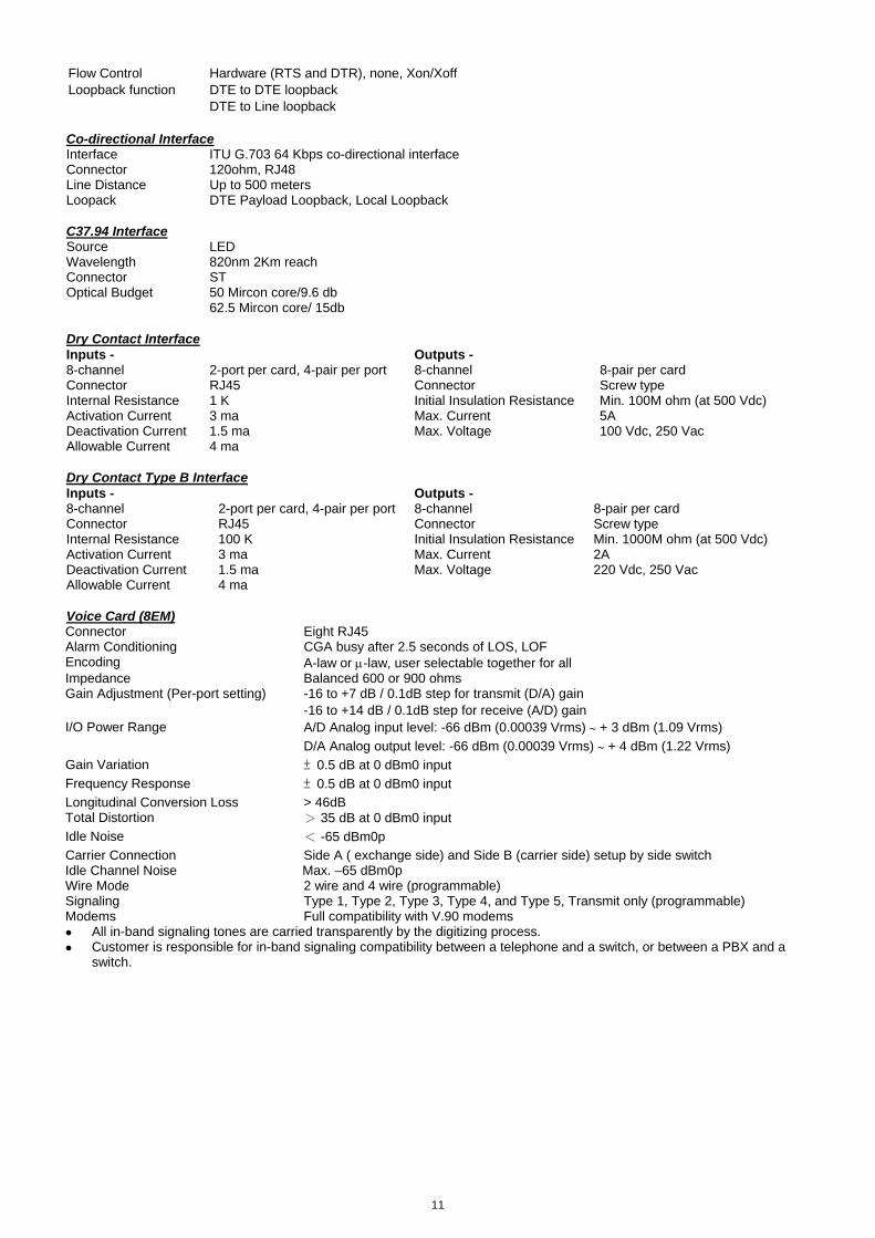
11
Flow Control Hardware (RTS and DTR), none, Xon/Xoff Loopback function DTE to DTE loopback DTE to Line loopback Co-directional Interface Interface ITU G.703 64 Kbps co-directional interface Connector 120ohm, RJ48 Line Distance Up to 500 meters Loopack DTE Payload Loopback, Local Loopback C37.94 Interface Source LED Wavelength 820nm 2Km reach Connector ST Optical Budget 50 Mircon core/9.6 db
62.5 Mircon core/ 15db Dry Contact Interface Inputs - Outputs - 8-channel 2-port per card, 4-pair per port 8-channel 8-pair per card Connector RJ45 Connector Screw type Internal Resistance 1 K Initial Insulation Resistance Min. 100M ohm (at 500 Vdc) Activation Current 3 ma Max. Current 5A Deactivation Current 1.5 ma Max. Voltage 100 Vdc, 250 Vac Allowable Current 4 ma Dry Contact Type B Interface Inputs - Outputs - 8-channel 2-port per card, 4-pair per port 8-channel 8-pair per card Connector RJ45 Connector Screw type Internal Resistance 100 K Initial Insulation Resistance Min. 1000M ohm (at 500 Vdc) Activation Current 3 ma Max. Current 2A Deactivation Current 1.5 ma Max. Voltage 220 Vdc, 250 Vac Allowable Current 4 ma Voice Card (8EM) Connector Eight RJ45 Alarm Conditioning CGA busy after 2.5 seconds of LOS, LOF Encoding A-law or μ-law, user selectable together for all Impedance Balanced 600 or 900 ohms Gain Adjustment (Per-port setting) -16 to +7 dB / 0.1dB step for transmit (D/A) gain
-16 to +14 dB / 0.1dB step for receive (A/D) gain I/O Power Range A/D Analog input level: -66 dBm (0.00039 Vrms) ~ + 3 dBm (1.09 Vrms)
D/A Analog output level: -66 dBm (0.00039 Vrms) ~ + 4 dBm (1.22 Vrms) Gain Variation ± 0.5 dB at 0 dBm0 input Frequency Response ± 0.5 dB at 0 dBm0 input Longitudinal Conversion Loss > 46dB Total Distortion > 35 dB at 0 dBm0 input Idle Noise < -65 dBm0p Carrier Connection Side A ( exchange side) and Side B (carrier side) setup by side switch Idle Channel Noise Max. –65 dBm0p Wire Mode 2 wire and 4 wire (programmable) Signaling Type 1, Type 2, Type 3, Type 4, and Type 5, Transmit only (programmable) Modems Full compatibility with V.90 modems
All in-band signaling tones are carried transparently by the digitizing process. Customer is responsible for in-band signaling compatibility between a telephone and a switch, or between a PBX and a
switch.

12
Voice Card 12 MAG (Magneto) Connector RJ11 x 12 Alarm Conditioning CGA busy after 2.5 seconds of LOS, LOF Encoding A-law or μ-law, user selectable together for all Impedance Balanced 600 or 900 ohms (for magneto telephone impedance ) Longitudinal Conversion Loss > 46dB Gain Adjustment -21 to +10 dB / 0.1dB step transmit & receive Signal/ Distortion > 25dB with 1004 Hz, 0dBm input Frequency Response - 0.25 to -1 dB from 300 to 3400 Hz, coincide with ITU-T G.712 Idle Channel Noise Max. –65 dBm0p Signaling Minimum Detectable Ringing Voltage
16 Vrms
Crank Detectable Across L1 & L2 Mode (Tip and Ring), L1 & GND Mode(Tip and GND) Crank Detected time Ringing Generation
Valid carnk: more than 250 ms Invalid crank: less than 160 ms Voltage: 76 Vrms (sine wave)
Frequency: 20Hz (with optional choices of 16, 25, 50 Hz) Ring duration Two optional modules are available for your choice:
1. 12MAG Normal operation: Ring duration depends on cranking time PLAR ON operation: when FXS pone off-hooked, the ring duration of the far-end magneto phone could be 0.5, 1.0, 2.0 or 4.0 sec 2. 12MAG-A Normal operation: Crank the phone for one time, and the ring duration of the far-end phone could be 0.7, 1.5 or 2.0 sec PLAR ON operation: when FXS phone off-hooked, the ring duration of the far-end magneto phone could be 0.7, 1.5 or 3.0 sec
Ringing Send Across L1 & L2 Mode (Tip and Ring), L1 & GND Mode(Tip and GND) Signaling Turn Magneto Phone crank (Ringing across Tip and Ring or Tip and Ground) Signaling Bit A,B,C,D Programable Signaling is carried transparently by the digitizing process. Use Magneto card default setting for communications between magneto telephones Use Magneto card PLAR mode setting for communications between a magneto telephone and a regular telephone

13
Conference Card
RS232 Interface Data Port 2-ports per card ASYNC Data Rate 300, 600, 1.2K, 2.4K, 4.8K, 9.6K, 19.2K SYNC not supported Connector Two DB9, DCE, female
FXS Voice Interface
Connector Two RJ11 Encoding G.723 Longitudinal Conversion Loss > 46dB Cross Talk Measure Max -70dBm0 Gain Adjustment transmit (D/A) gain 0, +6dB
receive (A/D) gain +6, 0, -6dB Signal/ Distortion > 25dB with 1004 Hz, 0dBm input Idle Channel Noise Max. –65 dBm0p Loop Resistance Max 1800 ohm FXS Loop Feed -48 Vdc with 25mA current limit per port
2 REN 20Hz 76 Vrms
FXS Ringing
2 sec on / 4 sec off for 1 min, or 1 sec on / 2 sec off for 30 sec (programmable)Signaling Loop Start, DTMF
E&M Voice Interface
Connector Two RJ45 Encoding G.723 Impedance Balanced 600 ohms Longitudinal Conversion Loss > 46dB Gain Adjustment transmit (D/A) gain 0, +6dB
receive (A/D) gain +6, 0, -6dB Signal/Distortion > 25dB with 1004 Hz, 0dBm input Idle Channel Noise Max. –65 dBm0p Carrier Connection Side A = exchange side, Side B = carrier side (Jumper selectable) Phone line power+12V Type P (Jumper enable) Operation mode Master, standard (Jumper selectable) Wire Mode 4 wire Signaling Type Type 1, Type 4, and Type 5 (Jumper selectable)
Single rainging for 5 sec only EM Ringing 2 sec on / 4 sec off for 1 min, or 1 sec on / 2 sec off for 30 sec (programmable)

14
Voice Card (12FXS, 12FXO, 24FXS, 24FXO) 12 FXS/FXO Connector Twelve RJ11 24 FXS/FXO Connector One RJ21X Female Alarm Conditioning CGA busy after 2.5 seconds of LOS, LOF Encoding A-law or μ-law, user selectable together for all AC Impedance Balanced 600 or 900 ohms (selectable together for all) Longitudinal Conversion Loss > 46dB Cross talk measure Max -70dBm0 Gain Adjustment -21 to +10 dB / 0.1dB step transmit & receive Signal/ Distortion > 25dB with 1004 Hz, 0dBm input Frequency Response - 0.25 to -1 dB from 300 to 3400 Hz, coincide with ITU-T G.712 Idle Channel Noise Max. –65 dBm0p Variation of Gain ±0.5dB FXO Ringing REN 0.5B (AC)
Detectable Ringing 25 Vrms Loop Resistance ≤ 1800 Ω DC Impedance (ON-HOOK) > 1M Ω DC Impedance (OFF-HOOK) 235 Ω @ 25mA feed 90 Ω @ 100mA feed FXS Loop Feed -48Vdc or -24Vdc with 25mA current limit per port
Jumper Selectable: 25mA, 30mA, 35mA FXS signalling Normal / Automatic Ring down FXS Ringing 1 REN at 5K meters per port
16.7Hz, 20Hz, 25Hz, 50Hz, user selectable for all ports 38 to 85 Vrms (sine wave), 76 Vrms for default Ring Voltage 2 sec on 4 sec off, or 1 sec on 2 sec off optional for PLAR Signaling Loop Start, DTMF, pulse, PLAR, Battery Reverse Optional Signaling (for special order)
Ground Start, Metering pulse (12 KHz, 16 KHz), and P( in PLAR mode, PLAR signalling bits are programmable.
Signaling Bit A,B,C,D Programable bit All in-band signaling tones are carried transparently by the digitizing process. Customer is responsible for in-band signaling compatibility between a telephone and a switch, or between a PBX and a switch. -24Vdc power is for FXS PCB version L and up

15
TDMoE
Combo Gigabit Ethernet(GbE) Interface Number of Ports 2 Speed 10/100/1000M bps Connector RJ45 for twisted pair GbE, LC for optical GbE, auto detection
Gigabit Ethernet(GbE) Interface
Number of Port 2
Speed 10/100/1000 BaseT
Connector RJ45
Ethernet Function
MDI/MDIX for 10/100/1000M BaseT auto-sensing Basic Features
Ping function contained ARP
Per port, programmable MAC hardware address learn limiting (max. MAC table 8192 (8k) entry)
Packet Delay Variation:
- Unframed T1: Up to 340 ms
- Framed T1: Up to 256 ms
- E1:up to 256 ms
- Framed T1 with CAS: Up to 192 ms
Packet Transparency Packet transparency support for all types of packet types including IEEE 802.1q VLAN and 802.1ad
(Q-in-Q)
QoS User configurable 802.1p CoS, ToS in out going IP frame
Ingress packet Rate limiting buckets per port for Ethernet port Traffic Control
Supporting Rate-based and Priority-based rate limiting for LAN port
Granularity:
a. From 64 Kbps to 1 Mbps in increments of 64 Kbps
b. From 1 Mbps to 100 Mbps in increments of 1 Mbps
c. From 100 Mbps to 1000 Mbps in increments of 10Mbps
Pause frame issued when the traffic exceeding the limited rate before packet dropped following
IEEE802.3X
Link Aggregation WAN support link aggregation
Jitter & Wander
PPM: per G.823 Traffic
PPB: per G.823 Synchronous Standard Compliance
IETF TDMoIP (RFC5087), SAToP (RFC4553), CESoPSN (RFC5086)
IEEE 802.1q, 802.1p, 802.1d, 802.3, 802.3u, 802.3x, 802.3z, 802.1s, 802.1w, 802.1AX

16
System Clock Clock Source Internal clock
4 aggregate lines clocks (STM-1/4 (OC-3/12)) External clocks: 2.048MHz or 2.048Mbps for STM-1/4, 1.544M bps for OC-3/12
Management Interface Console Electrical: RS232 Connector: DB9S (DCE) Protocol: Menu driven VT-100 SNMP SNMPv1, v3 (RFC1213, RFC2863, RFC1493) OSS interface 10/100BaseT FE (IEEE 802.3u ) Management channel Through DCC or 64Kbps channel for management Management protocol Router or bridge mode with HDLC / Ethernet type II Management function Telnet, SSH V2, RS232 console or GUI by management system Internet protocol IPv4 and IPv6(HDLC supported)
Alarm Input/Output Inputs Outputs Channel 3 Channel 2 (Major and Critical alarm)Internal Resistance 1K Fuse 3 (no, com, nc) Activation Current 3 ma Initial Insulation Resistance Min. 100M ohm (at 500Vdc)Deactivation Current 1.5 ma Maximum switching voltage 110 V DC, 125 V AC Allowable Current 4 ma
Diagnostics
CCA4 card Loopback Test Local loopback, payload loopback, line loopback BERT Test Optical interface Direction: to optical lines
E1/T1 card Loopback Test Local loopback, line loopback: BERT Test E1/T1 interface Direction: to optical lines, to tributary lines
Performance Monitor Performance Reports Performance Parameters: Error Block (EB), Background Block Error (BBE), Error Second(ES), Burst Error
Second (BES), Severe Error Second (SES), Unavailable Second(UAS)
System Alarm Alarm Cut Off, Power Loss/Uneqp, Fan Fail, Fan Module Uneqp, Overheat, TS Sync Loss, Logon and Logout, Optical Port Uneqp, Card In, Card Out, Card Type Mismatch, Card Port Number Mismatch, Card Fail, Card Registration, SNCP Switch, MSP Switch, Trib Protection Sync, Standby XCU Takeover, Standby Trib Takeover, XCU Sync, SFP Tx Fail, SFP Rx Fail, SFP Temperature, LS Protection, LS ID Mismatch
Line PI-LOS RS-LOF RS-TIM MS-SD MS-SF MS-AIS
MS-RDI MS-REI B1-BIP B2-BIP
Ho-Path AU-LOP AU-AIS HP-SD HP-SF HP-UNEQ HP-PLM HP-TIM HP-RED-P HP-RDI-S HP-RDI-C HP-LOM HP-REI
SDH
Lo-Path TU-LOP TU-AIS LP-SD LP-SF LP-UNEQ LP-PLM LP-TIM LP-RDI-P LP-RDI-S LP-RDI-C LP-REI LP-BIP
Line LOS-PI, LOF-S, TIM-S, SD-L , SF-L ,
AIS-L , RDI-L , REI-L UAS, B1-BIP, B2-BIP STS-Path LOP-P, AIS-P, SD-P, SF-P, UNEQ-P, PLM-P, TIM-P,
RDI-P-P, RDI-S-P, RDI-C-P, RDI-P-P, LOM-P, REI-P, B3-BIP-P
Alarm History Alarm History
SDH/SONET Line Alarm
SONET
VT-Path LOP-V, AIS-V, SD-V, SF-V, UNEQ-V, PLM-V, TIM-V, RDI-P-V, RDI-S-V, RDI-C-V, REI-V, BIP-V
Alarm Queue Contains up to 300 alarm records of latest alarm types, alarm severity, date, and time.

17
Physical /Electrical Dimensions 432.4 x 220 x 223.5 mm (W×H×D) Power Single/ Dual -48 Vdc: -36 to -75 Vdc, 150 Watts max.
Single/ Dual -24 Vdc: -18 to -36 Vdc, 150 Watts max Single/ Dual -125 Vdc: -40 to -150 Vdc, 100 Watts max
Temperature 0-55°C Humidity 0-95%RH (non-condensing) Mounting Desk-top stackable, 19” /23” rack mountable Line Power Supply Available only with DC power for G.SHDSL card only Power Consumption Max 110 Watts Certification O9550-A EN55022 Class A, EN50024, FCC Part 15 Class A, FCC Part 68, CS-03, IEC60950, UL60950 Compliance ITU G.664, G.703, G.704, G.706, G.707, G.711, G.712, G.732, G.736, G.747, G.775, G.783, G.806, G.823, G.826, O.151, V.11, V.28, V.54 , X.86. IETF SNMP v.3 (RFC2571~2575) Specifications for Loop-VV Y-BOX
LINE Connector BNC or RJ48C Port Number For Y-BOX with BNC connectors: 4 line ports For Y-BOX with RJ48C connectors: 16 line ports Protection For Y-BOX with BNC connectors: support 2 Quad E1 plug-in card, 4 active E1, 4 standby E1 For Y-BOX with RJ48C connectors: support 8 Quad E1 plug-in cards, 16 active E1, 16 standby E1 For Y-BOX with RJ48C connectors: support 8 Quad T1 plug-in cards, 16 active T1, 16 standby T1
Mechanical Height 44.5 mm/ 1.75 in Width 432 mm/ 17 in Depth 100 mm/ 3.9 in

18
Application Illustration:

19
ULSR Ring Application
Management PC
4E1
4E1 4E1
4E1
4E1
4E1 4E1
4E1
4E1
4E1
4E1
4E1
4E1
4E1
4E1
4E1
4E1
4E1 4E1
E1
Inband Mamnagement is set up byassigning1 DS0 (64K) for inband
management purposes on the TSltimeslot map of each AM 3440-A unit.
Clk: A/Internal
Clk: A/B Clk: A/B
Clk: A/B Clk: A/B
Note: ULSR ring does not suport E1 unframe mode. Users must use E1 frame mode to set up a ULSR ring.
Info www.dcbnet.com/contact.html
Data Comm for Business, Inc.2949 CR 1000 EDewey, IL 61840Voice 8004DCBNET (800.432.2638)Fax 217.897.1331
Web www.dcbnet.com