Long-term thermo-mechanical behaviour of energy piles in clay
32
HAL Id: hal-02879341 https://hal-enpc.archives-ouvertes.fr/hal-02879341 Submitted on 23 Jun 2020 HAL is a multi-disciplinary open access archive for the deposit and dissemination of sci- entific research documents, whether they are pub- lished or not. The documents may come from teaching and research institutions in France or abroad, or from public or private research centers. L’archive ouverte pluridisciplinaire HAL, est destinée au dépôt et à la diffusion de documents scientifiques de niveau recherche, publiés ou non, émanant des établissements d’enseignement et de recherche français ou étrangers, des laboratoires publics ou privés. Long-term thermo-mechanical behaviour of energy piles in clay van Tri Nguyen, Nanwangzi Wu, Yixiang Gan, Jean-Michel Pereira, Anh Minh Tang To cite this version: van Tri Nguyen, Nanwangzi Wu, Yixiang Gan, Jean-Michel Pereira, Anh Minh Tang. Long-term thermo-mechanical behaviour of energy piles in clay. Environmental Geotechnics, ICE-Publishing, In press, 10.1680/jenge.17.00106. hal-02879341
Transcript of Long-term thermo-mechanical behaviour of energy piles in clay
HAL Id: hal-02879341https://hal-enpc.archives-ouvertes.fr/hal-02879341
Submitted on 23 Jun 2020
HAL is a multi-disciplinary open accessarchive for the deposit and dissemination of sci-entific research documents, whether they are pub-lished or not. The documents may come fromteaching and research institutions in France orabroad, or from public or private research centers.
L’archive ouverte pluridisciplinaire HAL, estdestinée au dépôt et à la diffusion de documentsscientifiques de niveau recherche, publiés ou non,émanant des établissements d’enseignement et derecherche français ou étrangers, des laboratoirespublics ou privés.
Long-term thermo-mechanical behaviour of energy pilesin clay
van Tri Nguyen, Nanwangzi Wu, Yixiang Gan, Jean-Michel Pereira, AnhMinh Tang
To cite this version:van Tri Nguyen, Nanwangzi Wu, Yixiang Gan, Jean-Michel Pereira, Anh Minh Tang. Long-termthermo-mechanical behaviour of energy piles in clay. Environmental Geotechnics, ICE-Publishing, Inpress, �10.1680/jenge.17.00106�. �hal-02879341�

Long-term thermo-mechanical behaviour of energy pile in clay 1
V. T. NGUYEN 1, N. WU
2, Y. GAN
2, J. M. PEREIRA
1, A. M. TANG
1 2
1 Laboratoire Navier, UMR 8205, École des Ponts ParisTech, IFSTTAR, CNRS, UPE, France 3
2 School of Civil Engineering, The University of Sydney, NSW 2006, Australia 4
5
Corresponding author: 6
Dr. Anh Minh TANG 7
8
Ecole des Ponts ParisTech 9
Laboratoire Navier/Géotechnique (CERMES) 10
6-8 avenue Blaise Pascal 11
77455 MARNE-LA-VALLEE 12
France 13
Tel: +33.1.64.15.35.63 14
http://navier.enpc.fr 15
Email: [email protected] 16
17
18
ABSTRACT 19
In engineering practice, energy pile foundations are often designed for the lifetime of the 20
building. Thermal exchange between a pile and the surrounding soil depends on the annual 21
energy needs of the building, as heating mode in winter and cooling mode in summer. Thus, 22
energy pile foundations will undergo a heating-cooling cycle per year. In the present work, an 23
experimental method based on a small-scale pile model installed in saturated clay was used to 24
study the thermo-mechanical behaviour of energy pile under thermal cycles. 30 cycles were 25
applied (to represent a 30-year period if we neglect the daily cycles) while the pile head load 26
was maintained constant. Four tests were performed corresponding to pile head loads equal to 27
0, 20%, 40% and 60% of pile resistance. The results obtained show the increase of 28
irreversible pile head settlement with the thermal cycles. In order to better interpret the 29
experimental results, the finite element method is used to simulate numerically the 30
experiments. That allows highlighting the important role of pile thermal 31
contraction/expansion in the pile/soil interaction under thermo-mechanical loading. 32
KEYWORDS: energy pile, numerical modelling, physical modelling, saturated clay, thermal 33
cycles, thermo-mechanical behaviour. 34
35
INTRODUCTION 36
37
Pile foundations are used to erect a structure on an underground with poor load bearing 38
properties. The energy piles (also called “heat exchanger piles”) are the foundation piles that 39
are used also as heat exchangers. A system of heat exchanger pipes is embedded in such piles 40
allowing the exchanges of thermal energy between the ground and the building via a fluid 41
circulating in the pipes. This system combined with a heat pump allows extracting heat from 42
the soil in winter and re-injecting back heat to the soil in summer (Abuel-Naga et al., 2015; 43
de Santayanal et al., 2019). Thus, energy pile foundation is subjected to a heating-cooling 44
cycle per year, which reflects seasonal temperature variations. These annual thermal cycles 45
would then modify the soil/pile interaction from the thermo-mechanical point of view. In 46
spite of various studies on the thermo-mechanical behaviour of energy piles, few works have 47
investigated their long-term behaviour. Actually, to deal with this aspect, some studies 48
investigated the mechanical behaviour of energy piles subjected to numerous thermal cycles, 49
which represent the seasonal pile temperature variations (Ng et al., 2014; Pasten and 50
Santamarina, 2014; Suryatriyastuti et al., 2014; Di Donna and Laloui, 2015; Olgun et al., 51
2015; Saggu and Chakraborty, 2015; Ng et al., 2016; Bidarmaghz et al., 2016; Vieira and 52
Maranha, 2016; Nguyen et al., 2017). In these studies, numerical methods are usually used 53
and experimental methods are mainly based on physical modelling. 54
55
Among the numerical methods, the conventional load transfer method is the simplest one. 56
Suryatriyastuti et al. (2014) used this method, combined with additional mechanisms for 57
predicting degradation behaviour of pile-soil interface under thermal cycles, and investigated 58
the behaviour of free- and restraint-head pile in loose sand. The results show a ratcheting of 59
pile head settlement under a constant working load and a decrease in pile head force for the 60
restraint-head pile after 12 thermal cycles. Pasten and Santamarina (2014) developed a 61
modified one-dimensional load transfer model to predict the displacement of pile elements. 62
The results show that the axial force changes mainly in the middle of pile length when the 63
pile works under a heating phase. But in a cooling phase the axial force changes are 64
negligible. Besides, the irreversible settlement of pile reaches a plateau after several thermal 65
cycles. 66
Besides the load transfer method, the finite element method is also used to investigate long-67
term thermo-mechanical behaviour of energy piles. Saggu and Chakraborty (2015) 68
investigated the behaviour of a floating and end-bearing pile in loose and dense sand under 69
various thermal cycles by using the finite element method. The result shows an important 70
settlement of the pile after the first thermal cycle. A similar result can be found in the 71
numerical study of Olgun et al. (2015) where pile head displacement and axial stress were 72
investigated under three different climatic conditions for 30 years. After 30 annual thermal 73
cycles, even if the pile was progressively cooled, the axial stress along the pile tended to 74
increase. A decrease in axial stress was observed during heating. This was explained by the 75
difference in the thermal dilation between the pile and the soil during the thermal loading 76
process. Ng et al. (2016) studied the horizontal stress change of soil element close to the pile 77
when the pile is subjected to 50 heating-cooling cycles. The results show that the horizontal 78
stress along the pile depth decreased with thermal cycles. In addition, the irreversible 79
settlement of pile due to the decrease of the shaft resistance leads to the densification of soil 80
below the pile toe and thus the decrease of the rate of pile’s settlement. 81
Few studies have investigated the long-term thermo-mechanical behaviour of energy pile in 82
clay. Di Donna and Laloui (2015) have developed a numerical model to estimate the 83
additional displacement of pile and stress-strain state at the soil-pile interface. The result 84
indicates that the upper part of pile heaves in the heating phase and settles in the cooling 85
phase. The irreversible settlement of the pile is observed in the first cycle, but in the 86
following cycles the vertical displacement of the pile is almost reversible. A greater plastic 87
strain was obtained within the soil mass at points located close to the soil-pile interface. 88
Vieira and Maranha (2016) investigated the behaviour of a floating pile model in clay soil 89
under different constant static loads and seasonal temperature variations during five years 90
using the finite element method. The considered soil is saturated and normally consolidated. 91
The results indicate that when the pile works with a high factor of safety, its displacement is 92
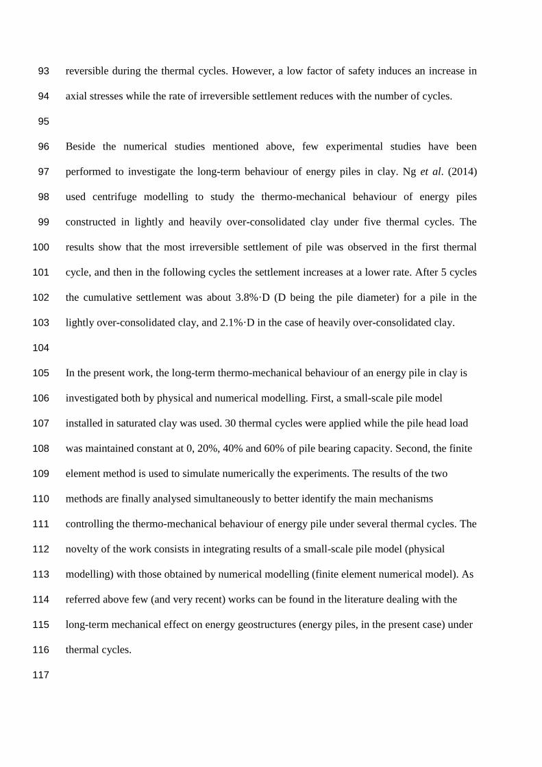
reversible during the thermal cycles. However, a low factor of safety induces an increase in 93
axial stresses while the rate of irreversible settlement reduces with the number of cycles. 94
95
Beside the numerical studies mentioned above, few experimental studies have been 96
performed to investigate the long-term behaviour of energy piles in clay. Ng et al. (2014) 97
used centrifuge modelling to study the thermo-mechanical behaviour of energy piles 98
constructed in lightly and heavily over-consolidated clay under five thermal cycles. The 99
results show that the most irreversible settlement of pile was observed in the first thermal 100
cycle, and then in the following cycles the settlement increases at a lower rate. After 5 cycles 101
the cumulative settlement was about 3.8%·D (D being the pile diameter) for a pile in the 102
lightly over-consolidated clay, and 2.1%·D in the case of heavily over-consolidated clay. 103
104
In the present work, the long-term thermo-mechanical behaviour of an energy pile in clay is 105
investigated both by physical and numerical modelling. First, a small-scale pile model 106
installed in saturated clay was used. 30 thermal cycles were applied while the pile head load 107
was maintained constant at 0, 20%, 40% and 60% of pile bearing capacity. Second, the finite 108
element method is used to simulate numerically the experiments. The results of the two 109
methods are finally analysed simultaneously to better identify the main mechanisms 110
controlling the thermo-mechanical behaviour of energy pile under several thermal cycles. The 111
novelty of the work consists in integrating results of a small-scale pile model (physical 112
modelling) with those obtained by numerical modelling (finite element numerical model). As 113
referred above few (and very recent) works can be found in the literature dealing with the 114
long-term mechanical effect on energy geostructures (energy piles, in the present case) under 115
thermal cycles. 116
117

PHYSICAL MODELING 118
The pile model is made of an aluminium tube with internal and external diameters of 18 mm 119
and 20 mm, respectively. The length of the tube is 800 mm and it is sealed at the bottom. Its 120
external surface was coated with sand to imitate the roughness of a full-scale bored pile. 600 121
mm of the pile was embedded in saturated clay (see Figure 1). 122
10
0
548 mm
60
0 m
m
A
Geotextile
Porous plastic
80
0 m
m
Tensiometer
Water
container
164 110
LVDT
30
0 m
m
S4S2 S3
S1
30
0 m
m
Force gauge Loading
S1: Temperature transducer inside the pileS2÷4: Temperature transducer distributed in soil
123
Figure 1. Experiment setup 124
125

The pile temperature is controlled by a metallic U-tube inserted inside it and connected to a 126
cryostat. A temperature sensor (accuracy equals ±0.01°C) is embedded inside the pile, at 300-127
mm depth, to monitor its temperature during the experiments. The axial load applied to the 128
pile head is controlled by deadweight (more details can be found in Yavari et al., 2014 on a 129
similar setup) and measured by a force sensor. The pile head displacement is measured by a 130
displacement sensor (LVDT) with an accuracy of ±0.001 mm. Temperature in soil is 131
measured by three sensors embedded at 300-mm depth and 20, 40, 80 mm from the pile axis. 132
133
Speswhite Kaolin clay was used in this study. It has a clay fraction of 30%, a liquid limit of 134
57%, a plastic limit of 33% and a particle density of 2.60 Mg/m3. Clay powder was mixed 135
with water by using a soil mixer to achieve a water content of 29%. It is then stored in a 136
sealed box for one month for moisture homogenization. Compaction was performed, by layer 137
of 50-mm thickness, using an electrical vibratory hammer. The soil mass used for the 138
compaction of each layer was controlled to obtain a dry density of 1.45 Mg/m3 (degree of 139
saturation equals 95% and void ratio equals 0.79). After the compaction of the first six layers, 140
the model pile was installed in place, and the remaining soil layers were completed. At the 141
vicinity of the pile model, a small metal hammer was used to avoid damaging the pile. 142
143
To control the quality of the compaction procedure, soil samples (20 mm in diameter) were 144
cored from the compacted soil mass for the determination of dry density and water content. 145
The created hole was refilled afterwards prior to the test with energy pile. Results show that 146
the dry density and the water content are relatively uniform with depth and they are close to 147
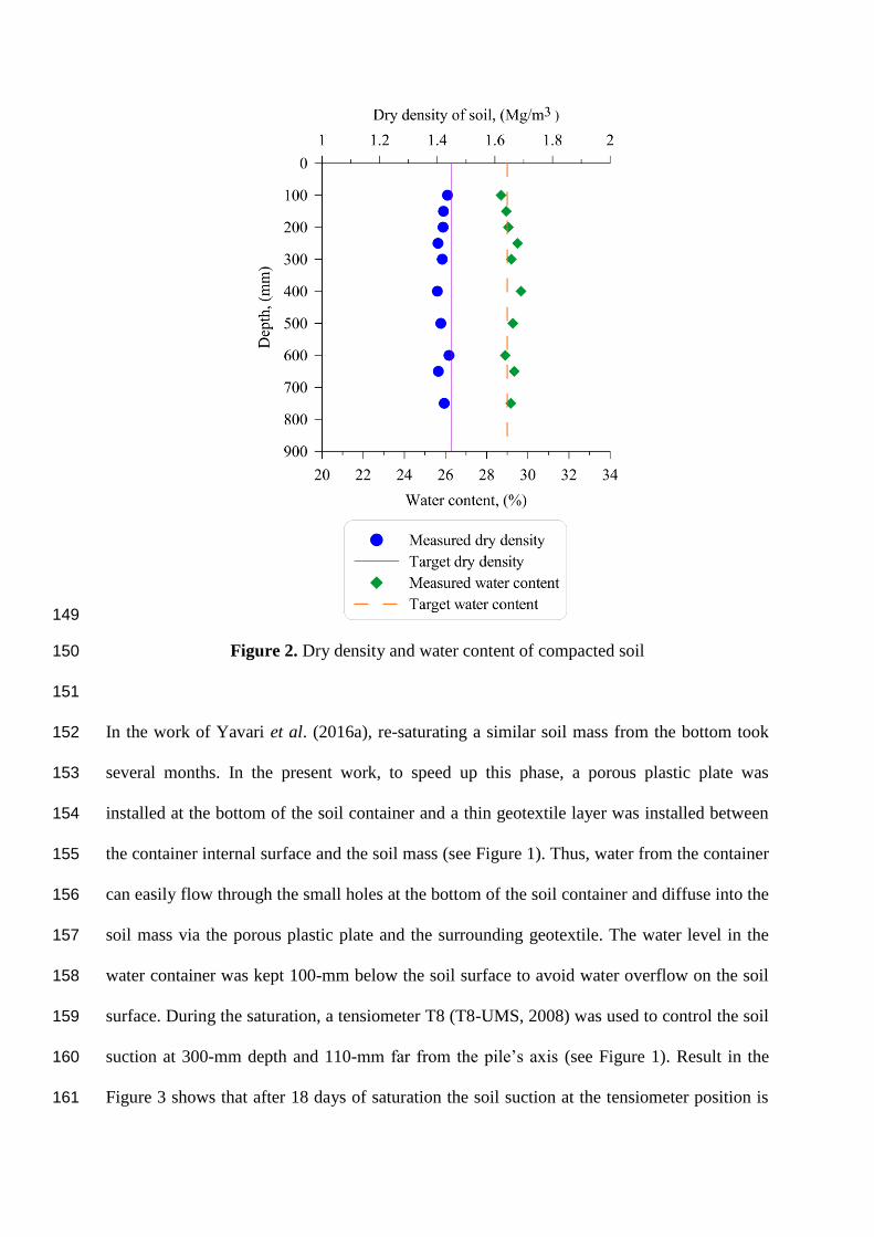
the target values (Figure 2). 148
149
Figure 2. Dry density and water content of compacted soil 150
151
In the work of Yavari et al. (2016a), re-saturating a similar soil mass from the bottom took 152
several months. In the present work, to speed up this phase, a porous plastic plate was 153
installed at the bottom of the soil container and a thin geotextile layer was installed between 154
the container internal surface and the soil mass (see Figure 1). Thus, water from the container 155
can easily flow through the small holes at the bottom of the soil container and diffuse into the 156
soil mass via the porous plastic plate and the surrounding geotextile. The water level in the 157
water container was kept 100-mm below the soil surface to avoid water overflow on the soil 158
surface. During the saturation, a tensiometer T8 (T8-UMS, 2008) was used to control the soil 159
suction at 300-mm depth and 110-mm far from the pile’s axis (see Figure 1). Result in the 160
Figure 3 shows that after 18 days of saturation the soil suction at the tensiometer position is 161

very close to zero. The tensiometer was then removed and the resulting hole was refilled to 162
avoid its influence on the thermo-mechanical behaviour of the pile. The saturation process 163
was kept for 45 days in total to ensure the full saturation of the soil mass. In should be noted 164
that, during the saturation, the soil container was covered on its surface to avoid water 165
evaporation and heat exchange. Moreover, the saturation system was maintained during the 166
subsequent thermo-mechanical experiment to ensure that the soil is always saturated. 167
168
169
170
Figure 3. Evolution of soil suction during the saturation process (measured by tensiometer) 171
172
Before conducting the experiment, temperature of soil and pile was kept at 20 C for one 173
week. This temperature is close to the room temperature during that period. After the 174
saturation process, the pile was initially subjected to a mechanical load (test A1) to determine 175
its ultimate bearing capacity. A series of load steps was applied to the pile head with 176
increments of 50 N, each loading step being maintained for one hour, following the French 177
Standard (Afnor, 1999). The results, shown in Figure 4, are similar to those obtained by 178
Yavari et al. (2016a). That confirms the repeatability of the applied experimental procedure. 179
180
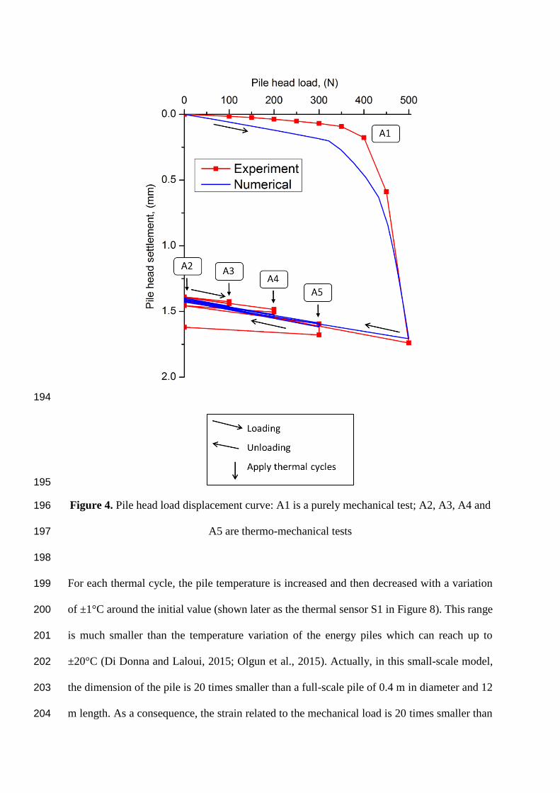
In the test A1, the pile was loaded up to 500 N, which corresponds also to the pile’s bearing 181
capacity. After this test, the pile head load was removed. In the test A2, 30 thermal cycles 182
were performed while no load was applied to the pile head. Afterward, the pile head was 183
loaded up to 20% of the pile’s capacity prior to the application of 30 thermal cycles (test A3 184
shown in Figure 4). At the end of these cycles, the pile head load was removed and then a 185
load corresponding to 40% of the pile’s capacity was applied. 30 thermal cycles were then 186
performed under this load (test A4). A similar procedure was applied for test A5 187
corresponding to 60% of pile’s capacity. This procedure is similar to that applied by Yavari et 188
al. (2016a) where only one thermal cycle was applied per load step. All the five tests were 189
performed on the same soil mass. The mechanical test (A1) was performed at first to identify 190
the pile’s capacity. That allowed better define the programme for the subsequent thermo-191
mechanical tests (A2-A5). Yavari et al. (2016a) found that loading the pile to its ultimate 192
bearing capacity and then unload it did not modify its behaviour during the subsequent tests. 193
194
195
Figure 4. Pile head load displacement curve: A1 is a purely mechanical test; A2, A3, A4 and 196
A5 are thermo-mechanical tests 197
198
For each thermal cycle, the pile temperature is increased and then decreased with a variation 199
of ±1°C around the initial value (shown later as the thermal sensor S1 in Figure 8). This range 200
is much smaller than the temperature variation of the energy piles which can reach up to 201
±20°C (Di Donna and Laloui, 2015; Olgun et al., 2015). Actually, in this small-scale model, 202
the dimension of the pile is 20 times smaller than a full-scale pile of 0.4 m in diameter and 12 203
m length. As a consequence, the strain related to the mechanical load is 20 times smaller than 204

that at the full scale (Laloui et al., 2006; Ng et al., 2014). For this reason, the temperature 205
variation was reduced 20 times in order to have a thermal strain of the pile 20 times smaller 206
than that at the full scale. Each thermal cycle is completed within 24 hours, which started 207
with a heating period of 4 hours, and followed by a cooling period of 4 hours, finally the 208
remaining time corresponded to active heating to return to the initial temperature. 209
210
NUMERICAL MODELING 211
Axisymmetric finite element model 212
The finite element analysis was performed by using the commercial FEA software, ABAQUS 213
V6.16. To model the physical experiment, two-dimensional axisymmetric model is 214
established (as shown in Figure 5) and fully coupled 4-node temperature-pore pressure-215
displacement element (CAX4PT) and 4-node bilinear displacement-temperature element 216
(CAX4T) are used for the regions of soil and pile, respectively. Soil is assumed fully 217
saturated throughout the loading cycles and the top 100 mm capillary zone in physical model 218
is ignored. Pore pressure at top surface of soil is opened to air but no heat flow escapes from 219
top surface. Circular hollow section aluminium pile is modelled by solid pile with the 220
equivalent mass density. Soil is modelled by the modified Cam-clay model and the pile is 221
described by linear-elasticity model. For contact properties, the friction coefficient at the soil-222
pile interface is assumed to be tan ϕ, where ϕ is the soil friction angle. Note that a relatively 223
large thermal conductance is chosen at pile-soil interface to reduce the interfacial thermal 224
contact resistance. Lateral pressure coefficient is assumed based on the Meyerhof correlation, 225
, by taking the pressure at 2/3 depth of pile for averaging pressure 226
along the pile to estimate , and OCR is approximately 160. The calculation of OCR is 227
based on the ratio of the historical maximum pressure and the current experienced pressure. 228
The former is calculated based on the Cam-Clay model parameters from Lv et al. (2017), for 229

NCL, i.e., 560 kPa with the experimentally measured void ratio of 0.79. As a result, =8 is 230
adopted for the numerical simulation and it is within a reasonable range since preparation of 231
physical model involves pre-compaction process. All parameters in simulation are 232
summarized in Table 1 and Table 2, and the constitutive parameters of soil can be referred to 233
Lv et al. (2017). Initial temperature for the entire numerical model is assumed 20C as the 234
case of the physical model. Bottom and side boundaries are set as the constant temperature of 235
20C. Deformation of soil is fully fixed at the bottom and only horizontally fixed at the side, 236
while the top surface is free to deform. Finite sliding formulation is used at soil-pile interface. 237
Temperature variation with time in physical experiment is deemed to be an input parameter to 238
investigate settlement occurring under the cyclic thermal loading condition. To simplify the 239
model, the entire pile is going to experience temperature variation uniformly instead of the 240
water circulation process in experiment. Thirty heating and cooling cycles are applied in 241
every thermal loading stage after the given mechanical load. One complete thermal cycle 242
includes four different thermal phases: initial, heating, cooling, and reheating, which will 243
induce settlement fluctuation. 244
Table 1. Parameters of pile and soil in numerical modelling 245
Parameters Pile
(CHS aluminium)
Clay
(Speswhite Kaolin Clay)
Constitutive model Linear-elastic Modified Cam-clay
Dry density (Mg/m3) 1.32 1.45
Volumetric weight at saturated
state (kN/m3)
N/A 18.53
Young’s modulus E (kPa) 1.3E7 N/A
Poisson’s ratio ѵ* 0.33 0.25
Slope of critical state line M* N/A 0.98
Slope of virgin consolidation line N/A 0.14

* Soil properties are adopted from Lv et al. (2017). 246
Table 2. Other relevant parameters in numerical modelling 247
Volumetric weight of water
(kN/m3)
9.81
Friction coefficient tanϕ 0.47
Interfacial thermal conductance
(W/C*m2)
500
Lateral earth coefficient, 8
248
λ*
Slope of swelling line κ* N/A 0.012
Initial void ratio e0* N/A 1.6
Void ratio after compaction e1 N/A 0.79
Friction angle ϕ* N/A 25
Permeability k (m/s)* N/A 1E-8
Thermal expansion (/C) 2.3E-5 1E-6
Thermal conductivity (W/mC) 237 1.5
Specific heat capacity (J/kgC) 9E2 1.269E3

249
Figure 5. Geometry and boundary conditions of the numerical model 250
251
Mesh sensitivity study 252
Five different mesh convergence analyses were performed to study mesh dependency of the 253
numerical model. For the pile, uniform 1 mm, 2 mm and 3 mm seed size are applied in the 254
pile region respectively with unchanged 1mm mesh size at soil side of soil-pile interface to 255
find appropriate pile mesh size. It is found that 2 mm mesh size for the pile was sufficient and 256
then, mesh sizes of 1 mm, 1.5 mm and 2 mm are applied into soil side of soil-pile interface 257
region which enables in total 5 different types of mesh size combinations. At the far end, 258
bottom and side of soil, the mesh seed size was set to a fixed 20 mm value for all simulations. 259
Here only the purely mechanical loading condition, A1, was considered for this mesh 260
convergence study, which was similar to Wehnert et al. (2004) work. In Figure 6, load and 261

settlement curves for different mesh size combinations are given. The mesh “Pile 2 mm, Soil 262
1 mm” is selected since it is above the threshold (i.e. Pile 2 mm, soil 1.5 mm) compared with 263
the experimental data for the pure mechanical loading. This finer mesh provides a better 264
confidence for the results from later thermo-mechanical analyses, while only slightly 265
increases the demand on computational resources. 266
267
Figure 6. Mesh dependency results (A1) 268
RESULTS 269
Mechanical behaviour of pile 270
Experiment result (Exp.) of test A1 is shown in Figure 4. This load-settlement curve is based 271
on the settlement value at the end of each load step. After loading to 500 N the pile is 272
unloaded and the irreversible settlement of pile head is about 1.42 mm. The relationship 273
between the axial load and the pile head settlement during the loading is almost linear when 274
the axial load is smaller than 350 N. For axial load higher than this value, pile head 275
settlement increases significantly with the increase of axial load. 276
277
The numerical result (Num.) gives a similar behaviour of pile by using the parameters of pile 278
and soil shown in Tables 1 and 2. Analysis on the plastic points shows that during the loading 279
path, when the axial load is lower than 350 N, only few plastic points can be observed at the 280
pile toe. Interfacial friction is approaching maximum shear stress. Loading above this value 281
induces development of plastic zones, and this phenomenon can be observed by the quick 282
increase of pile head settlement. 283
284
Thermo-mechanical behaviour of pile 285
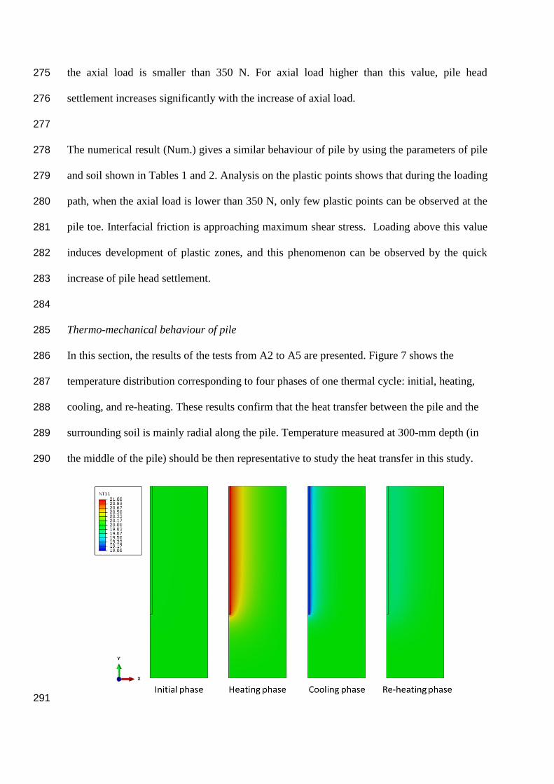
In this section, the results of the tests from A2 to A5 are presented. Figure 7 shows the 286
temperature distribution corresponding to four phases of one thermal cycle: initial, heating, 287
cooling, and re-heating. These results confirm that the heat transfer between the pile and the 288
surrounding soil is mainly radial along the pile. Temperature measured at 300-mm depth (in 289
the middle of the pile) should be then representative to study the heat transfer in this study. 290
291
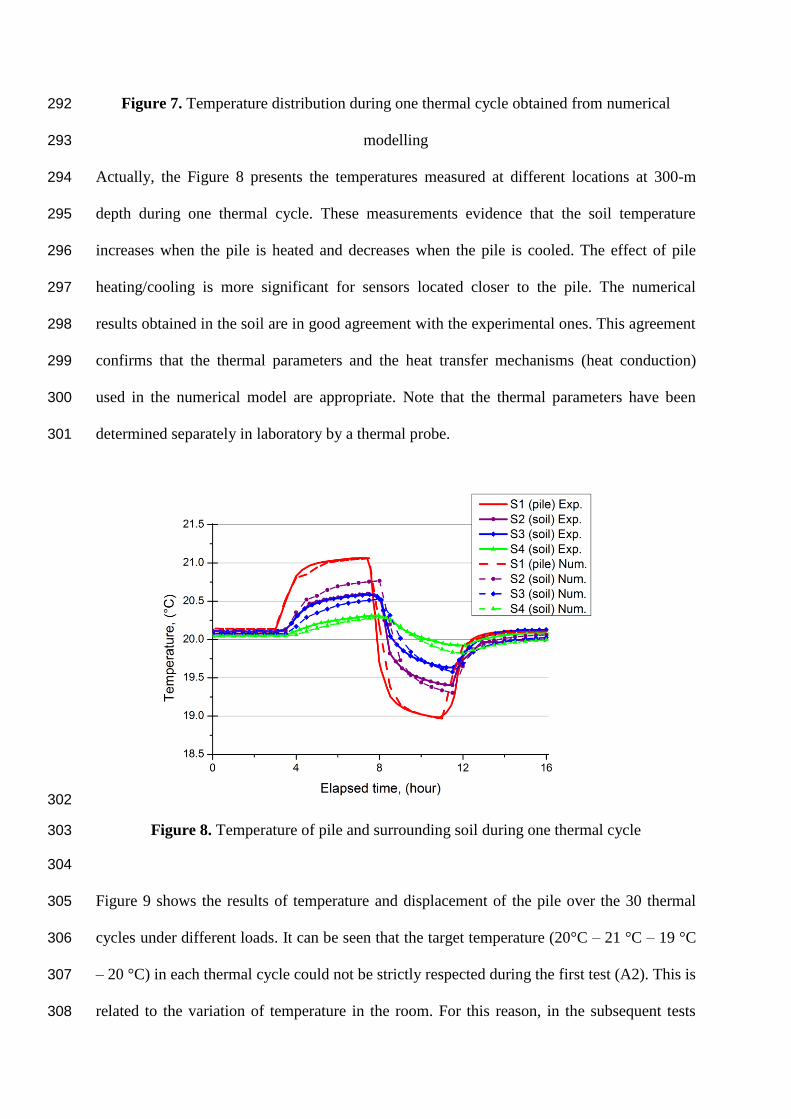
Figure 7. Temperature distribution during one thermal cycle obtained from numerical 292
modelling 293
Actually, the Figure 8 presents the temperatures measured at different locations at 300-m 294
depth during one thermal cycle. These measurements evidence that the soil temperature 295
increases when the pile is heated and decreases when the pile is cooled. The effect of pile 296
heating/cooling is more significant for sensors located closer to the pile. The numerical 297
results obtained in the soil are in good agreement with the experimental ones. This agreement 298
confirms that the thermal parameters and the heat transfer mechanisms (heat conduction) 299
used in the numerical model are appropriate. Note that the thermal parameters have been 300
determined separately in laboratory by a thermal probe. 301
302
Figure 8. Temperature of pile and surrounding soil during one thermal cycle 303
304
Figure 9 shows the results of temperature and displacement of the pile over the 30 thermal 305
cycles under different loads. It can be seen that the target temperature (20°C – 21 °C – 19 °C 306
– 20 °C) in each thermal cycle could not be strictly respected during the first test (A2). This is 307
related to the variation of temperature in the room. For this reason, in the subsequent tests 308
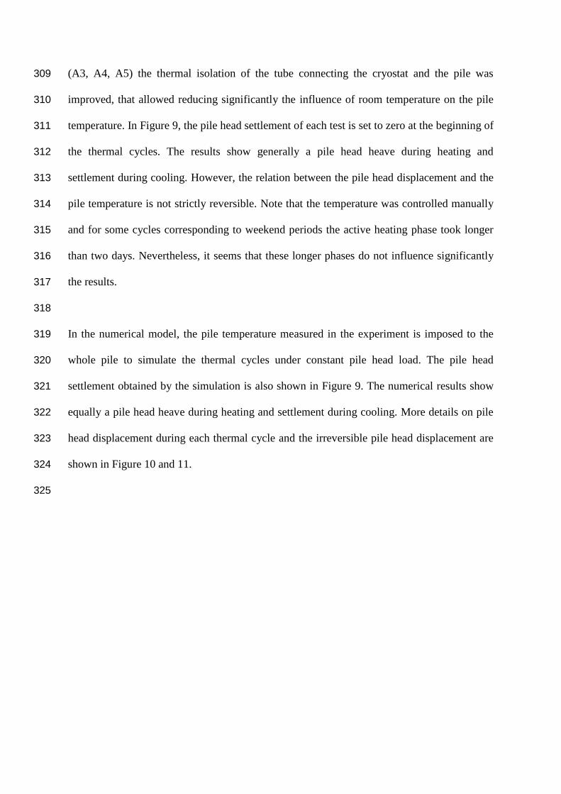
(A3, A4, A5) the thermal isolation of the tube connecting the cryostat and the pile was 309
improved, that allowed reducing significantly the influence of room temperature on the pile 310
temperature. In Figure 9, the pile head settlement of each test is set to zero at the beginning of 311
the thermal cycles. The results show generally a pile head heave during heating and 312
settlement during cooling. However, the relation between the pile head displacement and the 313
pile temperature is not strictly reversible. Note that the temperature was controlled manually 314
and for some cycles corresponding to weekend periods the active heating phase took longer 315
than two days. Nevertheless, it seems that these longer phases do not influence significantly 316
the results. 317
318
In the numerical model, the pile temperature measured in the experiment is imposed to the 319
whole pile to simulate the thermal cycles under constant pile head load. The pile head 320
settlement obtained by the simulation is also shown in Figure 9. The numerical results show 321
equally a pile head heave during heating and settlement during cooling. More details on pile 322
head displacement during each thermal cycle and the irreversible pile head displacement are 323
shown in Figure 10 and 11. 324
325
326
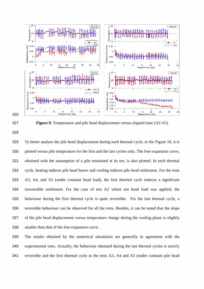
Figure 9. Temperature and pile head displacement versus elapsed time (A2-A5) 327
328
To better analyse the pile head displacement during each thermal cycle, in the Figure 10, it is 329
plotted versus pile temperature for the first and the last cycles only. The free expansion curve, 330
obtained with the assumption of a pile restrained at its toe, is also plotted. In each thermal 331
cycle, heating induces pile head heave and cooling induces pile head settlement. For the tests 332
A3, A4, and A5 (under constant head load), the first thermal cycle induces a significant 333
irreversible settlement. For the case of test A2 where not head load was applied, the 334
behaviour during the first thermal cycle is quite reversible. For the last thermal cycle, a 335
reversible behaviour can be observed for all the tests. Besides, it can be noted that the slope 336
of the pile head displacement versus temperature change during the cooling phase is slightly 337
smaller than that of the free expansion curve. 338
The results obtained by the numerical simulation are generally in agreement with the 339
experimental ones. Actually, the behaviour obtained during the last thermal cycles is strictly 340
reversible and the first thermal cycle in the tests A3, A4 and A5 (under constant pile head 341
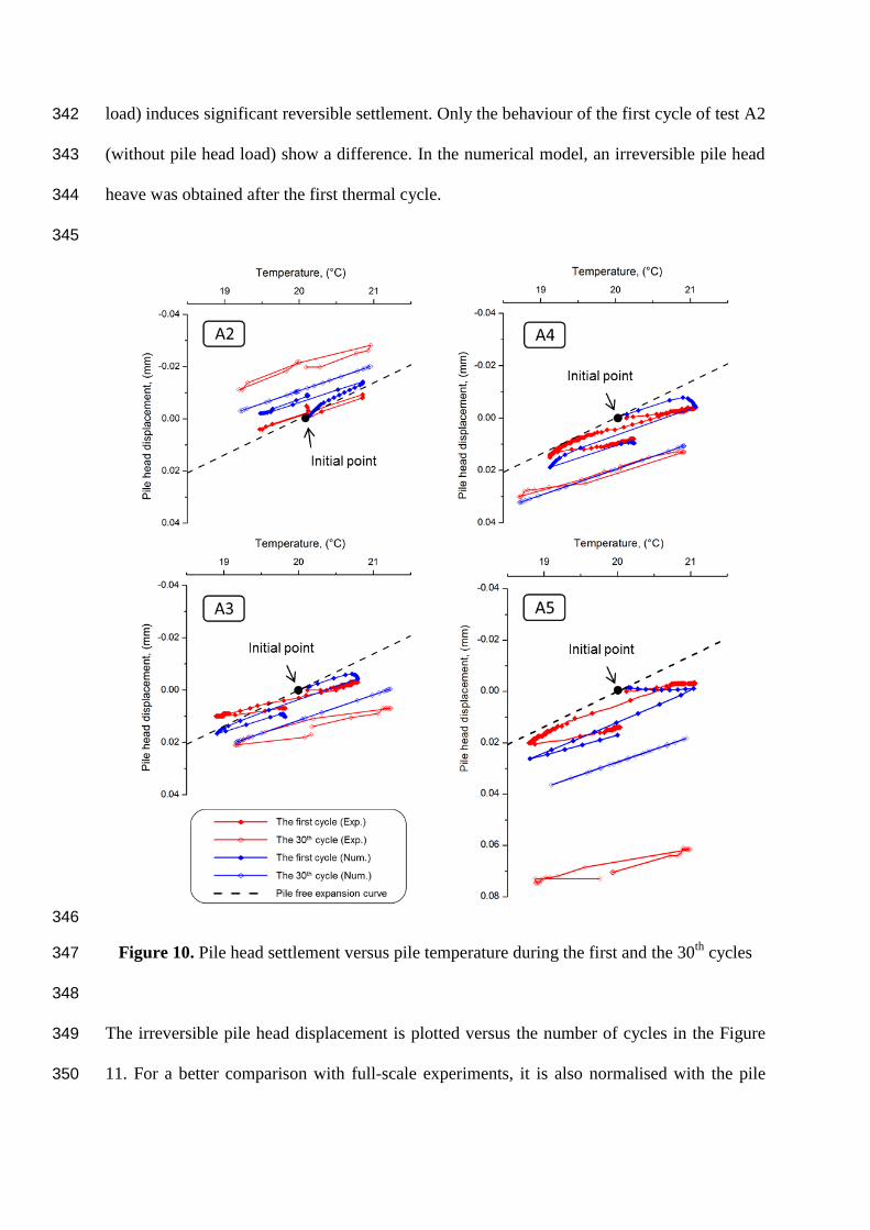
load) induces significant reversible settlement. Only the behaviour of the first cycle of test A2 342
(without pile head load) show a difference. In the numerical model, an irreversible pile head 343
heave was obtained after the first thermal cycle. 344
345
346
Figure 10. Pile head settlement versus pile temperature during the first and the 30th
cycles 347
348
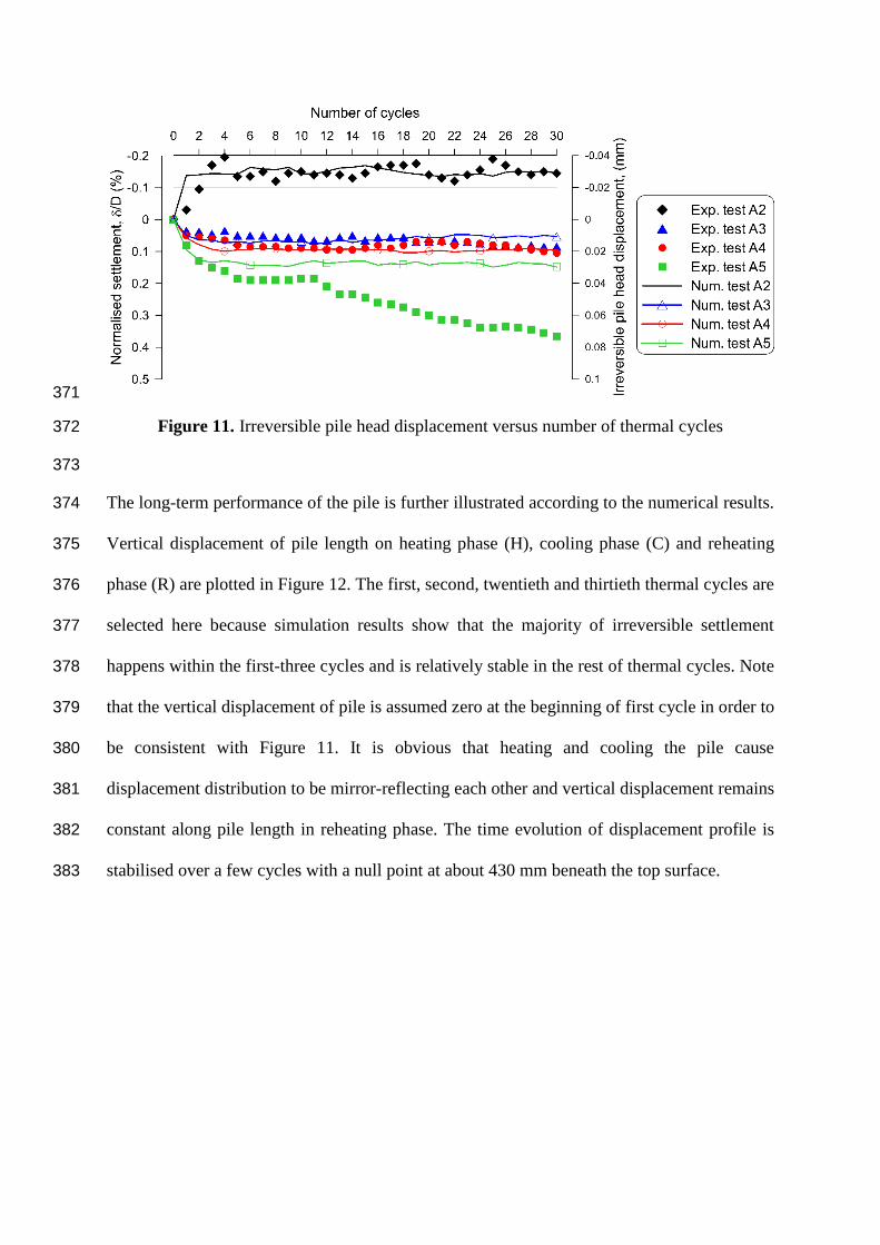
The irreversible pile head displacement is plotted versus the number of cycles in the Figure 349
11. For a better comparison with full-scale experiments, it is also normalised with the pile 350

diameter. For the test A2, the first cycle induces pile head heave up to 0.15% of pile diameter 351
with the numerical model. Afterward, the pile behaviour remains reversible during thermal 352
cycles. However, with the physical model, the first cycle induces only very small pile heave 353
(0.03% of pile diameter). But pile heave continues to increase during the subsequent cycles 354
and reaches 0.20% of pile diameter after four cycles. For the tests A3 and A4, the first 355
thermal cycles induce significant irreversible settlement. This latter become negligible for the 356
subsequent cycles. The behaviour of the pile in the test A5 is also similar to that of tests A3 357
and A4. However, after the tenth cycle, the irreversible settlement increases continuously 358
with the increase of the number of cycles. Besides, it can be noted that the irreversible 359
settlement depends on the pile head load; the higher the pile head load the higher the 360
irreversible settlement. For the test A5, the sudden increase of irreversible settlement from 361
the 10th
cycle should be related to some technical problems. The possible causes of problems 362
occurred could be: tilting of the pile at high cumulative settlement, failure of soil around the 363
pile toe, or other physico-chemical phenomena that occur in soil after a long period (several 364
months). 365
366
The results obtained by the numerical simulation are generally in good agreement with the 367
experimental ones. The only difference is related to the test A5 where the pile head 368
irreversible displacement remains constant event after the tenth cycle in the numerical 369
simulation. 370
371
Figure 11. Irreversible pile head displacement versus number of thermal cycles 372
373
The long-term performance of the pile is further illustrated according to the numerical results. 374
Vertical displacement of pile length on heating phase (H), cooling phase (C) and reheating 375
phase (R) are plotted in Figure 12. The first, second, twentieth and thirtieth thermal cycles are 376
selected here because simulation results show that the majority of irreversible settlement 377
happens within the first-three cycles and is relatively stable in the rest of thermal cycles. Note 378
that the vertical displacement of pile is assumed zero at the beginning of first cycle in order to 379
be consistent with Figure 11. It is obvious that heating and cooling the pile cause 380
displacement distribution to be mirror-reflecting each other and vertical displacement remains 381
constant along pile length in reheating phase. The time evolution of displacement profile is 382
stabilised over a few cycles with a null point at about 430 mm beneath the top surface. 383

384
Figure 12. Vertical displacement along the pile length (numerical results) 385
386
The total vertical stress along the pile length under different thermal cycles obtained from the 387
numerical simulation is presented in Figure 13. Only the results obtained from the first and 388
the last cycles are presented for clarity. Generally, heating the pile induces a slight increase of 389
vertical stress and cooling causes a decrease in vertical stress distribution along the pile 390
length. The behaviour obtained during the first cycle of test A2 is slightly different; heating 391
induces a decrease of vertical stress and cooling decreases again this latter. Besides, the 392
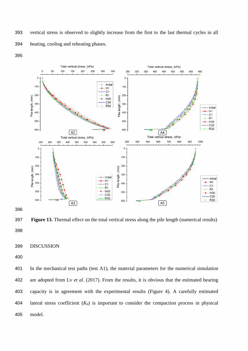
vertical stress is observed to slightly increase from the first to the last thermal cycles in all 393
heating, cooling and reheating phases. 394
395
396
Figure 13. Thermal effect on the total vertical stress along the pile length (numerical results) 397
398
DISCUSSION 399
400
In the mechanical test paths (test A1), the material parameters for the numerical simulation 401
are adopted from Lv et al. (2017). From the results, it is obvious that the estimated bearing 402
capacity is in agreement with the experimental results (Figure 4). A carefully estimated 403
lateral stress coefficient (K0) is important to consider the compaction process in physical 404
model. 405
406
In the test A2, the upward displacement of pile (as shown in Figure 9) during heating/cooling 407
cycles, observed on both physical and numerical models, can be explained by the stress state 408
shown in Figure 13. Actually, the test A2 starts after the mechanical unloading path of test 409
A1. At the end of the unloading path, the pile is still subjected to compressive stress (up to 410
300 kPa at its toe). Thermal cycles in test A2 induce thermal dilation/contraction of the pile. 411
This movement would release this compressive stress and heave the pile. The results shown 412
in Figure 13 evidence this stress release after thermal cycles. 413
414
In the subsequent tests (A3, A4, A5), irreversible settlement was observed during the first 415
thermal cycles. These results are in agreement with those observed by Ng et al. (2014) (using 416
centrifuge modelling) and Vieira & Maranha (2016) by using the finite element method. 417
However, only five thermal cycles were investigated in these works. Actually, the axial stress 418
profiles plotted in Figure 13 show that these thermal cycles increase the axial stress along the 419
pile. That means the thermal dilation/contraction of the pile facilitate the transmission of axial 420
pile head load to the pile toe. In the present works, both numerical and physical models show 421
that the pile settlement becomes reversible under thermal cycles at high number of cycles 422
(except for the test A5). 423
424
The numerical model shows behaviour similar to that obtained by physical model; the pile 425
settlement progressively achieves stable state due to densification process in each thermal 426
cycle. Especially the first thermal cycle shows good agreement with the experimental result 427
(Figure 10). The explanation of why numerical simulation is able to predict progressive 428
settlement owes to the use of the modified Cam-clay model as the constitutive model for soil. 429
The Cam-clay criterion follows the poro-plasticity rule that could more effectively simulate 430
densification process during thermal cyclic loads. Whereas Mohr-Coulomb model may not 431
well describe such soil behaviour (Yavari et al., 2014). Therefore, the present numerical 432
prediction of long-term thermal cyclic settlement of energy pile is able to predict 433
experimental data with relatively good agreement. 434
435
The results of Figure 10 show that the slope of the pile head displacement versus temperature 436
change during the cooling phase is slightly smaller than that of the free expansion curve. 437
Actually, similar tests on dry sand have shown that this slope is similar to the free expansion 438
curve (Kalantidou et al., 2012; Yavari et al., 2014). The behaviour observed in the present 439
work can be explained by the results shown in Figure 12. Actually, the null-point does not 440
locate at the pile toe but at 400 – 450 mm depth. For this reason, the pile head displacement 441
does not correspond to the free expansion of the whole pile length. 442
443
In the present work, the numerical model was able to reproduce correctly the thermo-444
mechanical behaviour of a small-scale energy pile under several thermal cycles. Note that the 445
range of the temperature variation in the physical model was limited to ±1 °C. This value is 446
much smaller than full-scale application (up to ±20 °C) in order to respect the scale effect. 447
Within this limited range of temperature variation, the soil parameters can be assumed to be 448
independent of temperature. However, for a higher temperature variation, the temperature 449
change can slightly modify the soil properties (Tang et al., 2008; Vega & McCartney, 2015; 450
Hong et al., 2016; Yavari et al., 2016b; Jacinto & Ledesma, 2017; Ghorbani et al., 2019). 451
The use of the present numerical model to predict the behaviour of real-scale energy 452
foundations should consider this aspect. 453
454
Results obtained in the present study would be helpful for studies on various types of thermo-455
active geostructures (Hoyos et al., 2015; Narsilio et al., 2017; Sanchez et al., 2017; Angelotti 456
and Sterpi, 2019; Baralis et al., 2019) 457
458
CONCLUSIONS 459
The long-term thermo-mechanical behaviour of energy pile is investigated in the present 460
work by using a small-scale model pile (physical modelling) and the finite element method 461
(numerical modelling). The following conclusions can be drawn: 462
Thermal cycles applied to the pile under constant pile head load induce stress 463
redistribution inside the pile. That can induce irreversible pile heave in the case 464
without pile head load and irreversible pile settlement in the case with pile head load. 465
The irreversible pile head settlement/heave is more important within the first thermal 466
cycles; it becomes negligible at high number of cycles. 467
The main mechanism that controls the soil/interaction during thermal cycles under 468
constant pile head load is the pile thermal contraction/dilation. The numerical model 469
can capture correctly the experimental result without considering the temperature 470
effect on soil’s parameters. 471
The preliminary results shown in this paper could warrant future numerical studies for the 472
serviceability design of geothermal energy piles. 473
474
ACKNOWLEDGEMENT 475
Dr. Gan acknowledges the financial support of Labex MMCD for his stay at Laboratoire 476
Navier. Labex MMCD benefits from a French government grant managed by ANR within the 477
frame of the national program Investments for the Future ANR-11-LABX-022-01. 478
479
REFERENCES 480
Abuel-Naga H, Raouf MIN, Raouf AMI, Nasser AG (2015) Energy piles: current state of 481
knowledge and design challenges, Environmental Geotechnics, 2(4), 195- 210. 482
AFNOR (1999) Essai statique de pieu isolé sous un effort axial, NF P 94-150-1, 28 pages. 483
Angelotti A and Sterpi D (2019). On the performance of energy walls by monitoring 484
assessment and numerical modelling: a case in Italy. Environmental Geotechnics, doi: 485
10.1680/jenge.18.00037. 486
Baralis M, Barla M, Bogusz W, Di Donna A, Ryzynski G & Zerun M (2019). Geothermal 487
potential of the NE extension Warsaw (Poland) metro tunnels. Environmental 488
Geotechnics, doi: 10.1680/jenge.18.00042. 489
Bidarmaghz A, Francisca FM, Makasis N and Narsilio GA (2016) Geothermal energy in 490
loess, Environmental Geotechnics, 3(4), 225 – 236, doi:10.1680/jenge.15.00025. 491
De Santayana FP, de Santiago C, de Groot M, Uchueguia J, Acros JL and Badenes B (2019). 492
Effect of thermal loads on pre-cast concrete thermopile in Valencia, Spain, 493
Environmental Geotechnics, doi: 10.1680/jenge.17.00103. 494
Di Donna A, and Laloui L (2015) Numerical analysis of the geotechnical behaviour of energy 495
piles, Int. J. Numer. Anal. Methods Geomech., 39(8), 861–888, doi:10.1002/nag.2341. 496
Ghorbani J, El-Zein A and Airey DW (2019) Thermo-elasto-plastic analysis of geosynthetic 497
clay liners exposed to thermal dehydration. Environmental Geotechnics, doi: 498
10.1680/jenge.17.00035. 499
Hoyos LR, DeJong JT, McCartney JS, Puppala AJ, Reddy KR & Zekkos D (2015) 500
Environmental geotechnics in the US region: a brief overview. Environmental 501
Geotechnics, 2(6), 319 – 325, doi: 10.1680/envgeo.14.00024. 502
Hong PY, Pereira JM, Cui YJ and Tang AM (2015) A two-surface thermomechanical model 503
for saturated clays. International Journal for Numerical and Analytical Methods in 504
Geomechanics, 40(7), 1059-1080, doi: 10.1002/nag.2474. 505
Jacinto AC and Ledesma A (2017). Thermo-hydro-mechanical analysis of a full-scale heating 506
test. Environmental Geotechnics, 4(2), 123 – 134, doi: 10.1680/jenge.15.00049. 507
Kalantidou A, Tang AM and Pereira JM (2012) Preliminary study on the mechanical 508
behaviour of heat exchanger pile in physical model. Géotechnique, 62(1), 1047-1051, 509
doi.org/10.1680/geot.11.T.013. 510
Laloui L, Nuth M and Vulliet L (2006) Experimental and numerical investigations of the 511
behaviour of a heat exchanger pile. International Journal for Numerical and Analytical 512
Methods in Geomechanics, 30(8) 763-781, doi: 10.1002/nag.499 513
Lv YR, Ng CWW, Lam SY, Liu HL and Ma LJ (2017) Geometric Effects on Piles in 514
Consolidating Ground: Centrifuge and Numerical Modeling. Journal of Geotechnical 515
and Geoenvironmental Engineering, 143(9), 04017040. 516
Narsilio GA, Sanchez M, Alvarellos J and Guimaraes L (2017) Editorial: XV Pan-American 517
Conference: selected papers on energy geotechnics. Environmental Geotechnics, 4(2), 518
67 – 69, doi: 10.1680/jenge.2017.4.2.67. 519
Ng, CWW, Shi C, Gunawan A, and Laloui L (2014) Centrifuge modelling of energy piles 520
subjected to heating and cooling cycles in clay, Géotechnique Letters, 4(4) 310–316, 521
doi:10.1680/geolett.14.00063. 522
Ng CWW, Ma QJ and Gunawan A (2016) Horizontal stress change of energy piles subjected 523
to thermal cycles in sand. Computers and Geotechnics, 78 (2016), 54–61, 524
doi:10.1016/j.compgeo.2016.05.003. 525
Nguyen VT, Tang AM and Pereira JM (2017) Long-term thermo-mechanical behavior of 526
energy pile in dry sand. Acta Geotechnica, 12(4), 729 – 737. 527
Olgun CG, Ozudogru TY, Abdelaziz SL and Senol A (2015) Long-term performance of heat 528
exchanger piles, Acta Geotechnica, 10(5), 553–569, doi:10.1007/s11440-014-0334-z. 529
Pasten C, Shin H, and Santamarina JC (2013) Long-Term Foundation Response to Repetitive 530
Loading, J. Geotech. Geoenvironmental Eng., 140(4), 4013036, 531
doi:10.1061/(ASCE)GT.1943-5606.0001052. 532
Pasten C, and Santamarina JC (2014) Thermally Induced Long-Term Displacement of 533
Thermoactive Piles, J. Geotech. Geoenvironmental Eng., 140(5), 6014003, 534
doi:10.1061/(ASCE)GT.1943-5606.0001092. 535
Saggu R, and Chakraborty T (2015) Cyclic Thermo-Mechanical Analysis of Energy Piles in 536
Sand. Geotechnical and Geoogical Engineering, 33(2), 321–342, doi:10.1007/s10706-537
014-9798-8. 538
Sanchez M, Falcao F, Mack M, Pereira JM, Narsilio GA and Guimaraes L (2017) Salient 539
comments from an expert panel on energy geotechnics. Environmental Geotechnics, 540
4(2), 135 – 142, doi: 10.1680/jenge.16.00008. 541
Suryatriyastuti ME, Mroueh H, and Burlon S (2014) A load transfer approach for studying 542
the cyclic behavior of thermo-active piles. Computers and Geotechnics, 55, 378–391, 543
doi:10.1016/j.compgeo.2013.09.021. 544
Tang AM, Cui YJ and Barnel N (2008) Thermo-mechanical behaviour of compacted swelling 545
clay. Géotechnique, 58(1) 45-54, doi: 10.1680/geot.2008.58.1.45 546
Vega A and McCartney JS (2015) Cyclic heating effects on thermal volume change of silt. 547
Environmental Geotechnics, 2(5), 257 – 268, 10.1680/envgeo.13.00022. 548

Vieira A and Maranha JR (2016) Thermoplastic Analysis of a Thermoactive Pile in a 549
Normally Consolidated Clay. International Journal of Geomechnics., 17(1) 4016030, 550
doi:10.1061/(ASCE)GM.1943-5622.0000666. 551
Yavari N, Tang AM, Pereira JM and Hassen G (2014) Experimental study on the mechanical 552
behaviour of a heat exchanger pile using physical modelling, Acta Geotechnica, 9(3), 553
385–398, doi:10.1007/s11440-014-0310-7. 554
Yavari N, Tang AM, Pereira JM and Hassen G (2016a), Mechanical behaviour of a small-555
scale energy pile in saturated clay, Géotechnique, 66(11), 878-887, 556
doi:10.1680/jgeot.15.T.026. 557
Yavari N, Tang AM, Pereira JM and Hassen G (2016b) Effect of temperature on the shear 558
strength of soils and soil/structure interface. Canadian Geotechnical Journal, 53(7), 559
1186-1194, doi:10.1139/cgj-2015-0355. 560
Wehnert M and Vermeer PA (2004) Numerical analyses of load tests on bored piles. 561
Numerical methods in geomechanics–NUMOG IX, 505-511. 562
563
564