Environmentally Adaptive Acoustic Sensing, Communication ...
DISTRIBUTION STATEMENT A. Approved for public release; distribution unlimited.
Long Range Acoustic Communication in Deep Water
H.C. Song and W.S. Hodgkiss Marine Physical Laboratory
Scripps Institution of oceanography La Jolla, CA 92093-0238
phone: (858) 534-0954/1798 fax: (858) 534-7641 email: [email protected] / [email protected]
Award number: N00014-12-1-0054 http://scrippsscholars.ucsd.edu/hcsong
LONG TERM GOALS
Develop and experimentally confirm robust self-adaptive algorithms for coherent communications between a source and a towed array at very long ranges in deep water.
OBJECTIVE
Experimentally confirm that robust coherent acoustic communication is feasible between a source and receiving array at speed and depth at long ranges in deep water with separations as long as 2000 km.
APPROACH
Acoustic communication at long range in the ocean is challenging due to the substantial propagation loss, multipath delay spread, and channel variability. Analysis of deep-water data collected as part of the ONR Acoustic Thermometry of Ocean Climate (ATOC) program has suggested that coherent acoustic communications is feasible at long ranges [1,2]. By treating the tomography signals (m-sequence transmissions) as BPSK communication signals, successful recovery of the sequence of bits has been demonstrated. One example is from the ATOC Acoustic Engineering Test (AET) in November 1994 where 1023-digit m-sequences were transmitted at a 75 Hz center frequency to a 20-element (700 m aperture) vertical array at approximately 3250 km range in the NE Pacific Ocean [1]. Either spatial diversity using the 20-element vertical array for a single transmission or temporal diversity provided by the dynamic ocean itself using a single receiver element and multiple (17) transmissions separated by 2 to 4 hours were successfully exploited to achieve an information rate of 37.5 bits/s.
Another example is from HIFT (Heard Island Feasibility Test) where a source moving at 3 knots near Heard Island transmitted 255-digit m-sequences (57 Hz) to a bottom-moored receiver at Ascension Island at a distance of about 9200 km [2]. A combination of spatial and temporal
1

Report Documentation Page Form ApprovedOMB No. 0704-0188
Public reporting burden for the collection of information is estimated to average 1 hour per response, including the time for reviewing instructions, searching existing data sources, gathering andmaintaining the data needed, and completing and reviewing the collection of information. Send comments regarding this burden estimate or any other aspect of this collection of information,including suggestions for reducing this burden, to Washington Headquarters Services, Directorate for Information Operations and Reports, 1215 Jefferson Davis Highway, Suite 1204, ArlingtonVA 22202-4302. Respondents should be aware that notwithstanding any other provision of law, no person shall be subject to a penalty for failing to comply with a collection of information if itdoes not display a currently valid OMB control number.
1. REPORT DATE 30 SEP 2014 2. REPORT TYPE
3. DATES COVERED 00-00-2014 to 00-00-2014
4. TITLE AND SUBTITLE Long Range Acoustic Communication in Deep Water
5a. CONTRACT NUMBER
5b. GRANT NUMBER
5c. PROGRAM ELEMENT NUMBER
6. AUTHOR(S) 5d. PROJECT NUMBER
5e. TASK NUMBER
5f. WORK UNIT NUMBER
7. PERFORMING ORGANIZATION NAME(S) AND ADDRESS(ES) University of California San Diego,Scripps Institution ofOceanography,9500 Gilman Drive,La Jolla,CA,92093
8. PERFORMING ORGANIZATIONREPORT NUMBER
9. SPONSORING/MONITORING AGENCY NAME(S) AND ADDRESS(ES) 10. SPONSOR/MONITOR’S ACRONYM(S)
11. SPONSOR/MONITOR’S REPORT NUMBER(S)
12. DISTRIBUTION/AVAILABILITY STATEMENT Approved for public release; distribution unlimited
13. SUPPLEMENTARY NOTES
14. ABSTRACT
15. SUBJECT TERMS
16. SECURITY CLASSIFICATION OF: 17. LIMITATION OF ABSTRACT Same as
Report (SAR)
18. NUMBEROF PAGES
6
19a. NAME OFRESPONSIBLE PERSON
a. REPORT unclassified
b. ABSTRACT unclassified
c. THIS PAGE unclassified
Standard Form 298 (Rev. 8-98) Prescribed by ANSI Std Z39-18
diversity referred to as synthetic aperture communications (SAC) were exploited to demonstrate the feasibility of global-scale acoustic telemetry.
WORK COMPLETED
While acoustic tomography or thermometry experiments have focused mostly on the open oceans, there were two experiments conducted in the Arctic: TAP (Transarctic Acoustic Propagation) in 1994 [3] and ACOUS (Arctic Climate Observation using Underwater Sound) in 1998-1999 [4-5]. The upward refracting propagation in the Arctic causes sound to be continually reflected and scattered from the ice with losses increasing with frequency. At 20 Hz, however, scattering losses were acceptable and there was no loss of coherence due to ice reflection.
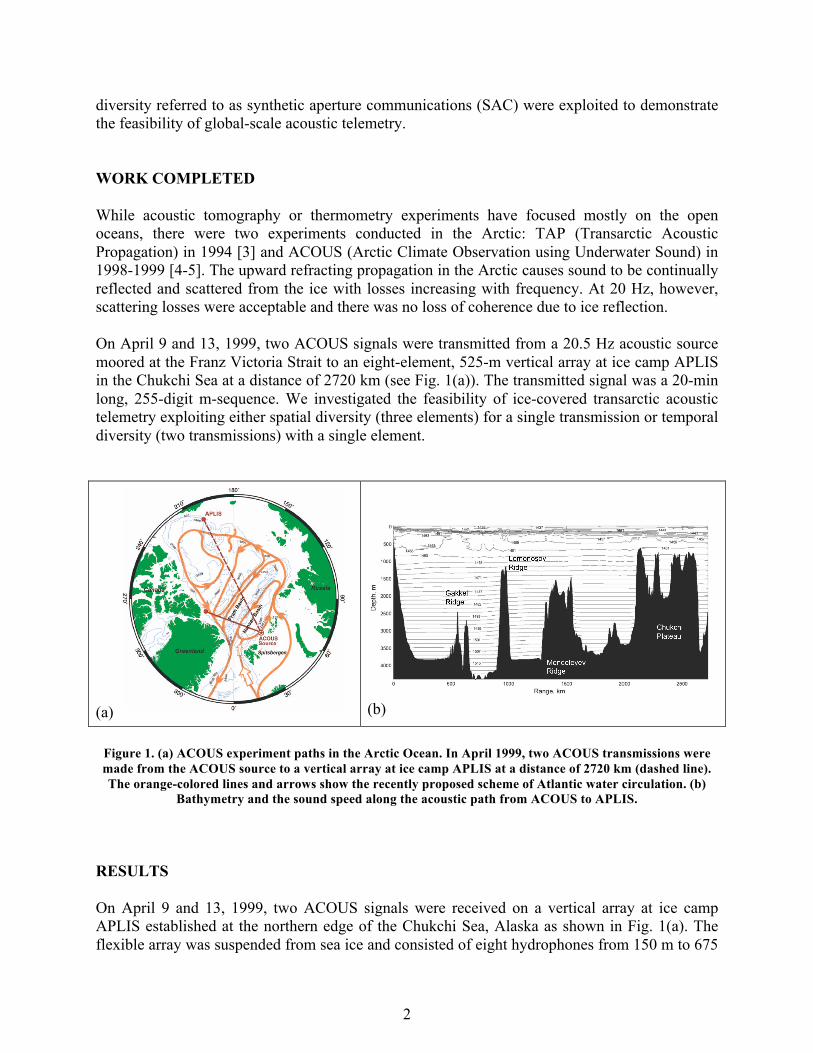
On April 9 and 13, 1999, two ACOUS signals were transmitted from a 20.5 Hz acoustic source moored at the Franz Victoria Strait to an eight-element, 525-m vertical array at ice camp APLIS in the Chukchi Sea at a distance of 2720 km (see Fig. 1(a)). The transmitted signal was a 20-min long, 255-digit m-sequence. We investigated the feasibility of ice-covered transarctic acoustic telemetry exploiting either spatial diversity (three elements) for a single transmission or temporal diversity (two transmissions) with a single element.
(a) (b)
Figure 1. (a) ACOUS experiment paths in the Arctic Ocean. In April 1999, two ACOUS transmissions were made from the ACOUS source to a vertical array at ice camp APLIS at a distance of 2720 km (dashed line). The orange-colored lines and arrows show the recently proposed scheme of Atlantic water circulation. (b)
Bathymetry and the sound speed along the acoustic path from ACOUS to APLIS.
RESULTS
On April 9 and 13, 1999, two ACOUS signals were received on a vertical array at ice camp APLIS established at the northern edge of the Chukchi Sea, Alaska as shown in Fig. 1(a). The flexible array was suspended from sea ice and consisted of eight hydrophones from 150 m to 675
2
m below the sea surface with element spacing of 75 m corresponding to the wavelength at the carrier frequency. The sound speed profile along the path to APLIS is shown in Fig. 1(b) along with the complex bathymetry. The two ridges (Lomonosov and Mendeleyev) do not rise above a depth of 1000 m, and therefore do not have significant impact of the low-order modes (1-4) at 20 Hz in the upward refracting Arctic acoustic channel. However, the seafloor topography in the region of the Chukchi Plateau is very uneven over which the depth was 600 m and thus the seafloor affected every mode of the ACOUS signal except for mode 1 which was confined to the upper 200 m. In April 1999, all regions along the ACOUS path to APLIS were almost entirely covered with sea ice.
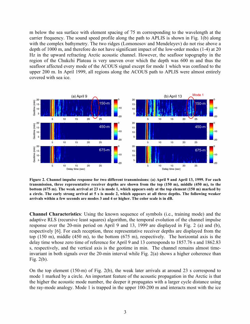
Figure 2. Channel impulse response for two different transmissions: (a) April 9 and April 13, 1999. For each transmission, three representative receiver depths are shown from the top (150 m), middle (450 m), to the bottom (675 m). The weak arrival at 23 s is mode 1, which appears only at the top element (150 m) marked by a circle. The early strong arrival at 5 s is mode 2, which appears at all three depths. The following weaker arrivals within a few seconds are modes 3 and 4 or higher. The color scale is in dB.
Channel Characteristics: Using the known sequence of symbols (i.e., training mode) and the adaptive RLS (recursive least squares) algorithm, the temporal evolution of the channel impulse response over the 20-min period on April 9 and 13, 1999 are displayed in Fig. 2 (a) and (b), respectively [6]. For each reception, three representative receiver depths are displayed from the top (150 m), middle (450 m), to the bottom (675 m), respectively. The horizontal axis is the delay time whose zero time of reference for April 9 and 13 corresponds to 1857.76 s and 1862.83 s, respectively, and the vertical axis is the geotime in min. The channel remains almost time-invariant in both signals over the 20-min interval while Fig. 2(a) shows a higher coherence than Fig. 2(b).
On the top element (150-m) of Fig. 2(b), the weak later arrivals at around 23 s correspond to mode 1 marked by a circle. An important feature of the acoustic propagation in the Arctic is that the higher the acoustic mode number, the deeper it propagates with a larger cycle distance using the ray-mode analogy. Mode 1 is trapped in the upper 100-200 m and interacts most with the ice
3

cover due to a short cycle distance. Therefore as it propagates, it loses more energy than higher-order modes over the 2700 km trans-Arctic path. Mode 1 is also visible in the top element of Fig. 2(a), but is much weaker.
On the other hand, the strong early arrivals at around 5 s that appear at all three depths in both signals are mode 2, which samples the upper 750 m and has less ice interaction and loss. Note that the dominant mode 2 is split in Fig. 2(a), indicating strong mode coupling due to the high-rise Chukchi Plateau shown in Fig. 1(b). The weaker arrivals following mode 2 within a few seconds are likely modes 3 and 4 or higher according to the analysis of mode filtering and modeling efforts presented in [5].
Communication Performance: On April 9, the input SNR at the APLIS array ranged from 2.9 dB to 4.2 dB for the bottom 5 elements (Chs 1-5) while the upper three elements (Chs 6-8) had SNRs below 0 dB. In particular, Ch 7 (225-m) has the lowest SNR which happens to be at the null of modes 2 and 3. For spatial diversity, we select two (Chs 2 and 4) or three (Chs 2, 4, and 5) elements with larger SNRs although the channels are not sufficiently different from each other due to few modes (2-3). The output SNR achieved with the three elements is 5.9 dB with a bit error rate (BER) of 0.8%, an almost 2 dB increase from the input SNRs. For the two-element case the output SNR decreases to 5 dB with BER of 2.4%. A fractionally-spaced DFE (2 samples per symbol) was applied to the feedforward filter, and the number of feedforward and feedback filter taps was 20 times the diversity order (2 or 3) and 10, respectively. The number of training symbols used for channel equalization was a single period of the m-sequence, i.e., NT=255 and the RLS forgetting factor was 0.998.
For temporal diversity, the two separate transmissions (April 9 and 13) are coherently processed using the single element at 450 m (Ch 4) displayed in the middle row of Fig.2. The performance in terms of output SNR is 6.1 dB with BER of 0.5%. It should be mentioned that for an individual reception alone, it was not possible to decode the symbols due to low SNRs (4.2 and 4.7 dB, respectively). The better performance with temporal diversity over spatial diversity is attributed to a combination of relatively higher input SNRs and more distinct diversity of the channels.
IMPACT/APPLICATIONS
Acoustic data communications is of broad interest for the retrieval of environmental data from in situ sensors, the exchange of data and control information between AUVs (autonomous undersea vehicles) and other off-board/distributed sensing systems and relay nodes (e.g. surface buoys), and submarine communications. In particular, acoustic communications with AUVs and gliders for data transmission and navigation in the Arctic would enable operations in ice-covered water providing additional valuable data. With the significant reduction of ice thickness and roughness in the Arctic today, it is expected that similar results can be achieved at long ranges at frequencies of 50-100 Hz, but this needs to be verified by new experiments.
4
PUBLICATIONS
1. H.C. Song, W.A. Kuperman, and W.S. Hodgkiss, “Basin-scale time reversal communications,” J. Acoust. Soc. Am. 125, 212-217, 2009 [published, refereed].
2. H.C. Song and M. Dzieciuch, “Feasibility of global-scale synthetic aperture communications (L),” J. Acoust. Soc. Am. 125, 8-10, 2009 [published, refereed].
3. P.N. Mikhalevsky, “Arctic acoustics,” in Encyclopedia of Ocean Sciences, edited by J.H. Steel, S.A. Thorp, and K.K. Turekian (Academic, London, 2011), pp. 53-61.
4. P.N. Mikhalevsky, A.N. Gavrilov, and A.B. Baggeroer, “The transarctic acoustic propagation experiment and climate monitoring in the Arctic,” IEEE J. Oceanic Eng. 24, 183-201 (1999).
5. A.N. Gavrilov and P.N. Mikhalevsky, “Low-frequency acoustic propagation loss in the Arctic ocean: Results of the Arctic climate observation using underwater sound experiment,” J. Acoust. Soc. Am. 119, 3694-3706 2006.
6. H.C. Song, P.N. Mikhalevely, and A.B. Baggeroer, “Transarctic acoustic telemetry (L),” J. Acoust. Soc. Am. 136, 1491-1494 (2014) [published, referred].
7. T. Shimura, Y. Watanabe, H. Ochi, and H.C. Song, “Long-range time reversal communication in deep water: Experimental results,” J. Acoust. Soc. Am. 132, EL49-EL53, 2012 [published, refereed].
8. T. Shimura, H. Ochi, and H.C. Song, "Experimental demonstration of multiuser communication in deep water using time reversal," J. Acoust. Soc. Am. 3223-3229, 2013 [published, referred].
9. K. Becker and J. Preston, “The ONR five octave research array (FORA) at Penn,” in Proc. IEEE OCEANS’03, 2607-2610, 2003.
10. H.C. Song, S. Cho, T. Kang, W.S. Hodgkiss, and J. Preston, “Long-range acoustic communication in deep water using a towed array,” J. Acoust. Soc. Am. 129, EL71-EL75, 2011 [published, refereed].
11. T. Kang, H.C. Song, and W.S. Hodgkiss, “Long-range multi-carrier acoustic communications in deep water with a towed horizontal array,” J. Acoust. Soc. Am. 131, 4665-4671, 2012 [published, refereed].
12. H.C. Song, “Acoustic communication in deep water exploiting multiple beams with a horizontal array,” J. Acoust. Soc. Am. 132, EL81-EL87, 2012 [published, refereed].
5

13. H.C. Song, W.S. Hodgkiss, “Diversity combining for long-range acoustic communication in deep water,” J. Acoust. Soc. Am. 132, EL68-EL73, 2012 [published, refereed].
14. Z. Liu, K. Yoo, T.C. Yang, S. Cho, H.C. Song, and D. Ensberg, "Long-range double differentially coded spread spectrum acoustic communications with a towed array," IEEE J. Oceanic Eng. 39 (3), 482-490 (2014) [published, referred].
15. H.C. Song, B.M. Howe, M.G. Brown, and R.K. Andrew, “Diversity-based acoustic communication with a glider in deep water (L),” J. Acoust. Soc. Am. 135, 1023-1026 (2014) [published, referred].
6