Long-Legged Hexapod Giacometti Robot Using Thin Soft ...
8
100 IEEE ROBOTICS AND AUTOMATION LETTERS, VOL. 3, NO. 1, JANUARY 2018 Long-Legged Hexapod Giacometti Robot Using Thin Soft McKibben Actuator Ahmad Athif Mohd Faudzi, Member, IEEE, Gen Endo, Member, IEEE, Shunichi Kurumaya, and Koichi Suzumori, Member, IEEE Abstract—This letter introduces a lightweight hexapod robot, Giacometti robot, made with long and narrow legs following the Alberto Giacometti’s sculpture conception. The goal is achieved by, first, using multiple links with thin and soft McKibben actuators, and second, choosing a leg design which is narrow in comparison to its body’s length and height, unlike conventional robot design. By such design characteristic, the leg will exhibit elastic deformations due to the low stiffness property of the thin link structure. Then, we model the leg structure and conduct the deflection analysis to confirm the capability of the leg to perform walking motion. The high force to weight ratio characteristics of the actuator provided the ability to drive the system, as shown by a static model and further validated experimentally. To compensate for the high elastic structural flexibility of the legs, two walking gaits namely customized Wave gait and Giacometti gait were introduced. The robot could walk successfully with both gaits at maximum speed of 0.005 and 0.05 m/s, respectively. It is envisaged that the lightweight Giacometti robot design can be very useful in legged robotic exploration. Index Terms—Giacometti structure, hexapod robot, legged lo- comotion, McKibben actuator, soft actuator. I. INTRODUCTION S INCE the time they introduced robots, researchers have developed robot’s performance with various sensory equipment in order to resolve many applied problems [1]–[6]. Although highly functional robots with qualified specification have been proposed, they have complicated control systems and heavy bodies. This causes technical problems related to safety in practical. For example, if a robot falls or hits something beyond its control, the damage to the robot and the surrounding would be very large. We have proposed a new concept robotics namely Giacometti robotics, which has the potential to solve these problems as the Manuscript received February 15, 2017; accepted June 20, 2017. Date of publication July 31, 2017; date of current version August 17, 2017. This letter was recommended for publication by Associate Editor C. Laschi and Editor Y. Sun upon evaluation of the reviewers’ comments. This work was supported by the JSPS KAKENHI under Grant 15K13907. (Corresponding author: Ahmad Athif Mohd Faudzi.) A. A. M. Faudzi is with the Faculty of Electrical Engineering, Universiti Teknologi Malaysia, Johor Bahru 81310, Malaysia, with the Centre for Artificial Intelligence and Robotics, Universiti Teknologi Malaysia International Campus, Kuala Lumpur 54100, Malaysia, and also with the Department of Mechanical Engineering, Tokyo Institute of Technology, Tokyo 152-8552, Japan (e-mail: [email protected]). G. Endo, S. Kurumaya, and K. Suzumori are with the Department of Me- chanical Engineering, Tokyo Institute of Technology, Tokyo 152-8552, Japan (e-mail: [email protected]; [email protected]; suzumori.k. [email protected]). Digital Object Identifier 10.1109/LRA.2017.2734244 Fig. 1. The Giacometti robot and its control system. design is very different from conventional robots [7]. This con- cept is inspired by the work of Alberto Giacometti, a Swiss sculpture who most of his artistic style of essential design is to remove flesh of the subject. Fig. 1 shows the proposed Hexapod Giacometti robot which aims for a large body structure with long legs but having lightweight and simple system for observa- tion purpose with minimal payload. Giacometti robotics aims to realize robots that are very light and simple, easy to handle, and essentially safe by emphasis on an essential function and less focus on the other functions. Other Giacometti robots includes 7 m-long Giacometti Arm, which uses helium-filled inflatable balloons that compensate for self-weight particularly developed in the feasibility of inspection [8]. From this design objective, our robot tries to reduce the weight of the robot by using soft and thin McKibben actuators and design small diameter leg size in comparison to its body’s length and height, which differs from the conventional robot design. Conventional design issues and principles for legged robots were presented by [6] where mechanical structure, leg design configuration, driving system and walking gait are among design procedures to consider. The Square-Cube Law [9] by Galileo (1564–1642) gives insight to the legged robot designer to decide the structural design [10]. From biomechanics point of view, the law mentioned that if allometric scaling were applied to an animal structure, its relative muscular strength would be severely reduced, since the cross section of its muscles would increase by the square of the scaling factor while its mass would increase by the cube of the scaling factor [11]. From this, robot designers understood that for bigger legged robots, the internal 2377-3766 © 2017 IEEE. Personal use is permitted, but republication/redistribution requires IEEE permission. See http://www.ieee.org/publications standards/publications/rights/index.html for more information. brought to you by CORE View metadata, citation and similar papers at core.ac.uk provided by Universiti Teknologi Malaysia Institutional Repository
Transcript of Long-Legged Hexapod Giacometti Robot Using Thin Soft ...

100 IEEE ROBOTICS AND AUTOMATION LETTERS, VOL. 3, NO. 1, JANUARY 2018
Long-Legged Hexapod Giacometti Robot Using ThinSoft McKibben Actuator
Ahmad Athif Mohd Faudzi, Member, IEEE, Gen Endo, Member, IEEE, Shunichi Kurumaya,and Koichi Suzumori, Member, IEEE
Abstract—This letter introduces a lightweight hexapod robot,Giacometti robot, made with long and narrow legs following theAlberto Giacometti’s sculpture conception. The goal is achievedby, first, using multiple links with thin and soft McKibbenactuators, and second, choosing a leg design which is narrow incomparison to its body’s length and height, unlike conventionalrobot design. By such design characteristic, the leg will exhibitelastic deformations due to the low stiffness property of the thinlink structure. Then, we model the leg structure and conduct thedeflection analysis to confirm the capability of the leg to performwalking motion. The high force to weight ratio characteristics ofthe actuator provided the ability to drive the system, as shown by astatic model and further validated experimentally. To compensatefor the high elastic structural flexibility of the legs, two walkinggaits namely customized Wave gait and Giacometti gait wereintroduced. The robot could walk successfully with both gaits atmaximum speed of 0.005 and 0.05 m/s, respectively. It is envisagedthat the lightweight Giacometti robot design can be very useful inlegged robotic exploration.
Index Terms—Giacometti structure, hexapod robot, legged lo-comotion, McKibben actuator, soft actuator.
I. INTRODUCTION
S INCE the time they introduced robots, researchers havedeveloped robot’s performance with various sensory
equipment in order to resolve many applied problems [1]–[6].Although highly functional robots with qualified specificationhave been proposed, they have complicated control systems andheavy bodies. This causes technical problems related to safetyin practical. For example, if a robot falls or hits somethingbeyond its control, the damage to the robot and the surroundingwould be very large.
We have proposed a new concept robotics namely Giacomettirobotics, which has the potential to solve these problems as the
Manuscript received February 15, 2017; accepted June 20, 2017. Date ofpublication July 31, 2017; date of current version August 17, 2017. This letterwas recommended for publication by Associate Editor C. Laschi and Editor Y.Sun upon evaluation of the reviewers’ comments. This work was supported bythe JSPS KAKENHI under Grant 15K13907. (Corresponding author: AhmadAthif Mohd Faudzi.)
A. A. M. Faudzi is with the Faculty of Electrical Engineering, UniversitiTeknologi Malaysia, Johor Bahru 81310, Malaysia, with the Centre for ArtificialIntelligence and Robotics, Universiti Teknologi Malaysia International Campus,Kuala Lumpur 54100, Malaysia, and also with the Department of MechanicalEngineering, Tokyo Institute of Technology, Tokyo 152-8552, Japan (e-mail:[email protected]).
G. Endo, S. Kurumaya, and K. Suzumori are with the Department of Me-chanical Engineering, Tokyo Institute of Technology, Tokyo 152-8552, Japan(e-mail: [email protected]; [email protected]; [email protected]).
Digital Object Identifier 10.1109/LRA.2017.2734244
Fig. 1. The Giacometti robot and its control system.
design is very different from conventional robots [7]. This con-cept is inspired by the work of Alberto Giacometti, a Swisssculpture who most of his artistic style of essential design is toremove flesh of the subject. Fig. 1 shows the proposed HexapodGiacometti robot which aims for a large body structure withlong legs but having lightweight and simple system for observa-tion purpose with minimal payload. Giacometti robotics aims torealize robots that are very light and simple, easy to handle, andessentially safe by emphasis on an essential function and lessfocus on the other functions. Other Giacometti robots includes7 m-long Giacometti Arm, which uses helium-filled inflatableballoons that compensate for self-weight particularly developedin the feasibility of inspection [8]. From this design objective,our robot tries to reduce the weight of the robot by using soft andthin McKibben actuators and design small diameter leg size incomparison to its body’s length and height, which differs fromthe conventional robot design.
Conventional design issues and principles for legged robotswere presented by [6] where mechanical structure, leg designconfiguration, driving system and walking gait are among designprocedures to consider. The Square-Cube Law [9] by Galileo(1564–1642) gives insight to the legged robot designer to decidethe structural design [10]. From biomechanics point of view,the law mentioned that if allometric scaling were applied toan animal structure, its relative muscular strength would beseverely reduced, since the cross section of its muscles wouldincrease by the square of the scaling factor while its mass wouldincrease by the cube of the scaling factor [11]. From this, robotdesigners understood that for bigger legged robots, the internal
2377-3766 © 2017 IEEE. Personal use is permitted, but republication/redistribution requires IEEE permission.See http://www.ieee.org/publications standards/publications/rights/index.html for more information.
brought to you by COREView metadata, citation and similar papers at core.ac.uk
provided by Universiti Teknologi Malaysia Institutional Repository

MOHD FAUDZI et al.: LONG-LEGGED HEXAPOD GIACOMETTI ROBOT USING THIN SOFT MCKIBBEN ACTUATOR 101
stresses grow linearly with scale and therefore the elements ofthe structures must be thick in proportion to the strength thusbigger diameter and rigid legs should be designed. Big robotslike Ambler with 2500 kg [4] and ATHLETE with 850 kg [5],have bigger structure and bigger leg diameter to support thebody, as they must carry proportionately higher weight. Theserobots may have advantage to negotiate larger steps and may bemore suitable for specific applications planetary exploration byAmbler and ATHLETE. Recently Ant-Roach, hexapod robothaving big structure and big leg diameter but having overallweight of only 32 kg was reported. It applies inflatable structuresusing polybag material controlled with pressurized air to makethe leg stiff [12]. On the other hand, thin legs architecture withsmall diameter was also proposed for legged robot. HexapodLunar rover from Institute of Automatics, Rome has straight legwith 2 DOF for each leg [13]. It consists of a hinge type rotaryjoint on its lateral axis and manipulates leg length by telescopicsliding structure at the knee joint making motion of the leg likethat of an articulated leg. The design can reduce the shear stressfor the leg and increase its rigidity.
Looking at the biological approach, a thin-legged insectwhich possesses non-proportional leg to body size like theGiacometti robot is the Opiliones, the animal commonly knownas “harvestman” [14]. Harvestman is known for its long andthin structure where the legs will have special characteristics ofelastic deformation from its low stiffness leg structure as one ofits attractive features. Previous work of R. Hodoshima and S.Hirose proposed ASURA I [15] and KUMO-I [16] respectivelywhich imitate the harvestman by having long slender rigid legsrelative to its body. Although the study proves that it is possiblefor smaller diameter of leg size to drive a bigger structure robot,it has limited motion and suffers from poor back drivability dueto its weight.
Therefore, Giacometti robot proposes to use lightweightstructure from the thin soft McKibben actuator as its drivingelements in antagonistic pairs and applies thin leg structure.The conventional McKibben muscle is bulky thus increases theoverall weight of other pneumatically driven robots such asPneupard [17] and AirBug [18]. As part of the Giacometticoncept of simplicity, the first stage evaluation does not ap-ply any sensor feedback reading unlike normal legged robots.The robot will fully rely on its mechanical body and leg struc-ture using simple control loop without much dependence on themain brain. A customized gait, namely Giacometti gait is spe-cially designed and proposed for the walking test. This conceptshows that there is an exception with the above Galileo Square-Cube Law as the leg diameter used in the design is relativelysmall.
The current study contributes to our knowledge by address-ing two issues; 1) new long-legged design concept, a shiftin paradigm from the Square-Cube Law with static analysisof leg model, 2) new walking gait with simple control sys-tem. The remainder of the letter is organized as follows. InSection II, the soft thin actuator characteristics are explained.The force and contraction ratio data of 4.0 mm actuator is pre-sented. Section III discusses robot design structure with the legmechanism and its static stress and curve analysis. Section IVexplains the system setup and discusses the customized Waveand Giacometti gait. The robot basic walking experiment usingboth gaits and other experiments are discussed in Section V.Finally, the letter concludes with a brief appraisal and futurerecommendation in Section VI.
Fig. 2. Contraction ratio (%) and contraction force at different input pressure(MPa).
II. THIN SOFT MCKIBBEN ACTUATOR
A. Actuator Characteristics
Soft actuators are presently gaining popularity in many robotsbecause of the advantages of high power-to-weight ratio, highcompliance, flexible structure, strong reliability for human useand low cost for manufacturing the actuators [19]. McKibbenactuator can generate high linearity in force [20] with low hys-teresis and dead zone at low pressure. Smaller diameter ofMcKibben actuator had been developed with many differentapplication [21]. We developed thin soft McKibben musclesfor mass production [22]. The muscles are light, small, andsuitable for simple systems [23]. The Giacometti robot applies4.0 mm McKibben actuators which will contract when beingpressurized with air. During contraction, the stiffness increasesand produces contraction force providing the robot motion. The4.0 mm silicone rubber tube is covered by 48 fibers of 0.22 mmTetron monofilament and braided with 18 degrees for optimumcontraction function of the actuator. Therefore, the overall outerdiameter of the actuator is 4.6 mm.
B. Force Characterization
The static characteristics of the McKibben muscles wereexperimentally obtained by changing the input pressure. Theactuators exhibit a contraction force proportional with thecontraction ratio. This is confirmed with force characterizationexperiments reported [24]. Fig. 2 shows the characteristics ofthe 4.0 mm actuator when pressurized from 0 MPa to 0.6 MPa.The static characteristics were investigated by measuring therelationship between the generated force and contraction ratiounder various pressure levels. The proposed operating pressurefor the Giacometti robot is between 0.3 to 0.4 MPa. The con-traction ratio of thin McKibben actuator is like some vertebraemuscle, which usually shortens by 25% or less [25]. The max-imum force of the actuator at 0.3 MPa and 0.4 MPa is around43 N and 65 N, respectively. Based on the contraction ratio andforce of the actuator, the leg mechanism design of the HexapodGiacometti is performed and will be describe in next section.
III. LEG MECHANISM AND ROBOT STRUCTURE
Insects normally have four main segments of coxa, femur,tibia and tarsus. Most of the length of insect leg is contributedby two long and nearly equally segments of femur and tibia.
102 IEEE ROBOTICS AND AUTOMATION LETTERS, VOL. 3, NO. 1, JANUARY 2018
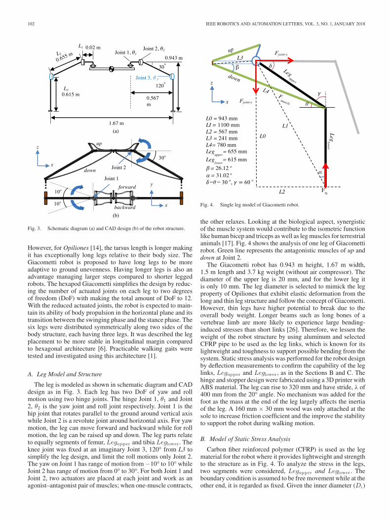
Fig. 3. Schematic diagram (a) and CAD design (b) of the robot structure.
However, for Opiliones [14], the tarsus length is longer makingit has exceptionally long legs relative to their body size. TheGiacometti robot is proposed to have long legs to be moreadaptive to ground unevenness. Having longer legs is also anadvantage managing larger steps compared to shorter leggedrobots. The hexapod Giacometti simplifies the design by reduc-ing the number of actuated joints on each leg to two degreesof freedom (DoF) with making the total amount of DoF to 12.With the reduced actuated joints, the robot is expected to main-tain its ability of body propulsion in the horizontal plane and itstransition between the swinging phase and the stance phase. Thesix legs were distributed symmetrically along two sides of thebody structure, each having three legs. It was described the legplacement to be more stable in longitudinal margin comparedto hexagonal architecture [6]. Practicable walking gaits weretested and investigated using this architecture [1].
A. Leg Model and Structure
The leg is modeled as shown in schematic diagram and CADdesign as in Fig. 3. Each leg has two DoF of yaw and rollmotion using two hinge joints. The hinge Joint 1, θ1 and Joint2, θ2 is the yaw joint and roll joint respectively. Joint 1 is thehip joint that rotates parallel to the ground around vertical axiswhile Joint 2 is a revolute joint around horizontal axis. For yawmotion, the leg can move forward and backward while for rollmotion, the leg can be raised up and down. The leg parts relateto equally segments of femur, Legupper and tibia Leglower . Theknee joint was fixed at an imaginary Joint 3, 120° from L3 tosimplify the leg design, and limit the roll motions only Joint 2.The yaw on Joint 1 has range of motion from −10° to 10°whileJoint 2 has range of motion from 0° to 30°. For both Joint 1 andJoint 2, two actuators are placed at each joint and work as anagonist–antagonist pair of muscles; when one-muscle contracts,
Fig. 4. Single leg model of Giacometti robot.
the other relaxes. Looking at the biological aspect, synergisticof the muscle system would contribute to the isometric functionlike human bicep and triceps as well as leg muscles for terrestrialanimals [17]. Fig. 4 shows the analysis of one leg of Giacomettirobot. Green line represents the antagonistic muscles of up anddown at Joint 2.
The Giacometti robot has 0.943 m height, 1.67 m width,1.5 m length and 3.7 kg weight (without air compressor). Thediameter of the upper leg is 20 mm, and for the lower leg itis only 10 mm. The leg diameter is selected to mimick the legproperty of Opiliones that exhibit elastic deformation from thelong and thin leg structure and follow the concept of Giacometti.However, thin legs have higher potential to break due to theoverall body weight. Longer beams such as long bones of avertebrae limb are more likely to experience large bending-induced stresses than short links [26]. Therefore, we lessen theweight of the robot structure by using aluminum and selectedCFRP pipe to be used as the leg links, which is known for itslightweight and toughness to support possible bending from thesystem. Static stress analysis was performed for the robot designby deflection measurements to confirm the capability of the leglinks, Legupper and Leglower , as in the Sections B and C. Thehinge and stopper design were fabricated using a 3D printer withABS material. The leg can rise to 320 mm and have stride, λ of400 mm from the 20° angle. No mechanism was added for thefoot as the mass at the end of the leg largely affects the inertiaof the leg. A 160 mm × 30 mm wood was only attached at thesole to increase friction coefficient and the improve the stabilityto support the robot during walking motion.
B. Model of Static Stress Analysis
Carbon fiber reinforced polymer (CFRP) is used as the legmaterial for the robot where it provides lightweight and strengthto the structure as in Fig. 4. To analyze the stress in the legs,two segments were considered, Legupper and Leglower . Theboundary condition is assumed to be free movement while at theother end, it is regarded as fixed. Given the inner diameter (Di)
MOHD FAUDZI et al.: LONG-LEGGED HEXAPOD GIACOMETTI ROBOT USING THIN SOFT MCKIBBEN ACTUATOR 103
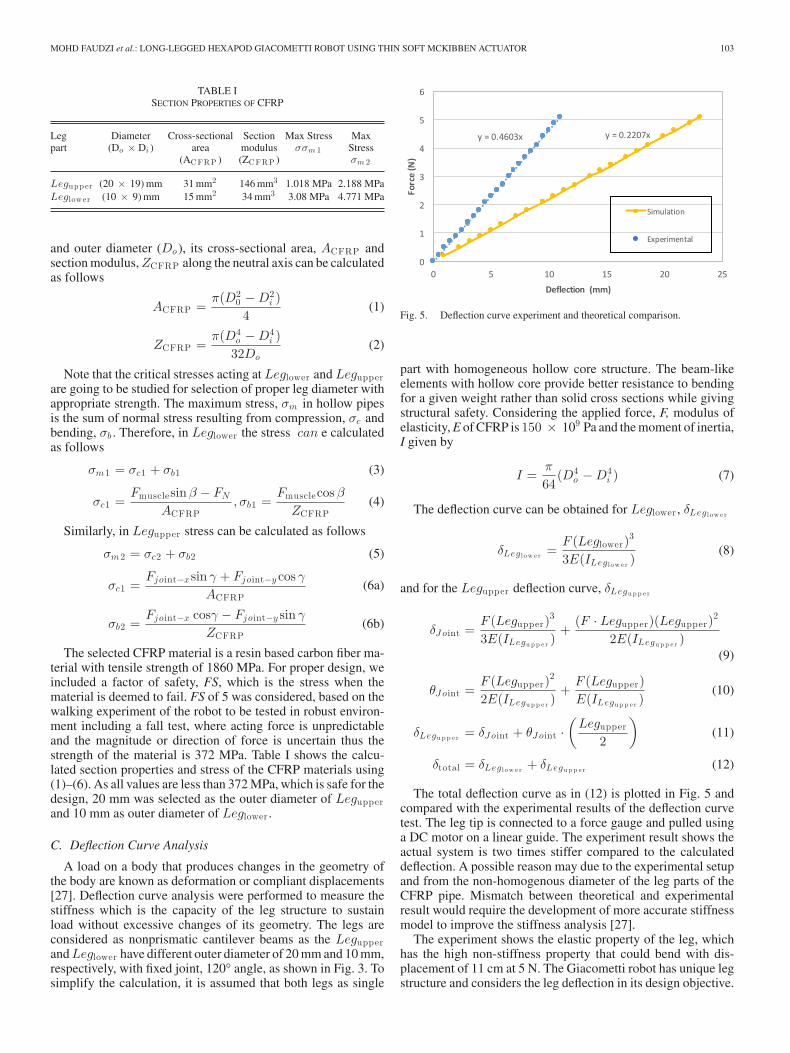
TABLE ISECTION PROPERTIES OF CFRP
Leg Diameter Cross-sectional Section Max Stress Maxpart (Do × Di ) area modulus σσm 1 Stress
(ACFRP ) (ZCFRP ) σm 2
Legupp er (20 × 19) mm 31 mm2 146 mm3 1.018 MPa 2.188 MPaLeglower (10 × 9) mm 15 mm2 34 mm3 3.08 MPa 4.771 MPa
and outer diameter (Do ), its cross-sectional area, ACFRP andsection modulus, ZCFRP along the neutral axis can be calculatedas follows
ACFRP =π(D2
0 − D2i )
4(1)
ZCFRP =π(D4
o − D4i )
32Do(2)
Note that the critical stresses acting at Leglower and Legupperare going to be studied for selection of proper leg diameter withappropriate strength. The maximum stress, σm in hollow pipesis the sum of normal stress resulting from compression, σc andbending, σb . Therefore, in Leglower the stress can e calculatedas follows
σm1 = σc1 + σb1 (3)
σc1 =Fmusclesin β − FN
ACFRP, σb1 =
Fmusclecos β
ZCFRP(4)
Similarly, in Legupper stress can be calculated as follows
σm2 = σc2 + σb2 (5)
σc1 =Fjoint−xsin γ + Fjoint−y cos γ
ACFRP(6a)
σb2 =Fjoint−x cosγ − Fjoint−y sin γ
ZCFRP(6b)
The selected CFRP material is a resin based carbon fiber ma-terial with tensile strength of 1860 MPa. For proper design, weincluded a factor of safety, FS, which is the stress when thematerial is deemed to fail. FS of 5 was considered, based on thewalking experiment of the robot to be tested in robust environ-ment including a fall test, where acting force is unpredictableand the magnitude or direction of force is uncertain thus thestrength of the material is 372 MPa. Table I shows the calcu-lated section properties and stress of the CFRP materials using(1)–(6). As all values are less than 372 MPa, which is safe for thedesign, 20 mm was selected as the outer diameter of Legupperand 10 mm as outer diameter of Leglower .
C. Deflection Curve Analysis
A load on a body that produces changes in the geometry ofthe body are known as deformation or compliant displacements[27]. Deflection curve analysis were performed to measure thestiffness which is the capacity of the leg structure to sustainload without excessive changes of its geometry. The legs areconsidered as nonprismatic cantilever beams as the Legupperand Leglower have different outer diameter of 20 mm and 10 mm,respectively, with fixed joint, 120° angle, as shown in Fig. 3. Tosimplify the calculation, it is assumed that both legs as single
Fig. 5. Deflection curve experiment and theoretical comparison.
part with homogeneous hollow core structure. The beam-likeelements with hollow core provide better resistance to bendingfor a given weight rather than solid cross sections while givingstructural safety. Considering the applied force, F, modulus ofelasticity, E of CFRP is 150 × 109 Pa and the moment of inertia,I given by
I =π
64(D4
o − D4i ) (7)
The deflection curve can be obtained for Leglower , δLeg l ow e r
δLeg l ow e r =F (Leglower)
3
3E(ILeg l ow e r )(8)
and for the Legupper deflection curve, δLegu p p e r
δJ oint =F (Legupper)
3
3E(ILegu p p e r )+
(F · Legupper)(Legupper)2
2E(ILegu p p e r )(9)
θJ oint =F (Legupper)
2
2E(ILegu p p e r )+
F (Legupper)E(ILegu p p e r )
(10)
δLegu p p e r = δJ oint + θJ oint ·(
Legupper
2
)(11)
δtotal = δLeg l ow e r + δLegu p p e r (12)
The total deflection curve as in (12) is plotted in Fig. 5 andcompared with the experimental results of the deflection curvetest. The leg tip is connected to a force gauge and pulled usinga DC motor on a linear guide. The experiment result shows theactual system is two times stiffer compared to the calculateddeflection. A possible reason may due to the experimental setupand from the non-homogenous diameter of the leg parts of theCFRP pipe. Mismatch between theoretical and experimentalresult would require the development of more accurate stiffnessmodel to improve the stiffness analysis [27].
The experiment shows the elastic property of the leg, whichhas the high non-stiffness property that could bend with dis-placement of 11 cm at 5 N. The Giacometti robot has unique legstructure and considers the leg deflection in its design objective.
104 IEEE ROBOTICS AND AUTOMATION LETTERS, VOL. 3, NO. 1, JANUARY 2018
D. Selection of Actuators Length
The actuators length for each part were decided based on ac-tuator characteristics of contraction ratio and force as discussedin Section II. Based on the characteristics experiment of the ac-tuator conducted in [24], it shows that the contraction ratio andforce are the same at any length of the actuator. However, thecontraction ratio changes at different pressure input e.g., 18.5%and 24% at 0.3 MPa and 0.35 MPa respectively.
The important aspect of the design is to ensure the robot can besupported with the contraction force of the muscles and possibleto locomote. Each leg has two degrees of freedom (DoF) ofroll and yaw, which requires 2 pairs of antagonistic muscles.First pair will perform roll motion of up and down, while theother pair executes yaw motion of forward and backward. Themuscles were named based on its function of up, down, forwardand backward. The pair of up and down muscles have differentlength however forward and backward muscles have the samelength. The actuators length is important to know the musclesactuation capability to drive with the amount of force needed.
The robot structure is designed to allow the Giacometti robotto support as much payload as possible by choosing the correctactuator’s length for stance position which applies the downmuscles. From Fig. 4, the moment equilibrium around the Joint2 is presented by (13)
Fmuscle =FN (sin α · L1)
(sin β · L3)(13)
where Fmuscle is the expected force required to support 1/3 ofthe whole payload of the system. Initially, it is considered thatthe robot will use minimum three legs for stance position. α isthe angle during stance position perpendicular with the rotationpoint. β is the angle between the platform and the muscle. δ isthe movements when the leg is raised up. Force exerted by thejoint can obtain by (14) and (15).
Fjoint−y = (Fmuscle · sin β) − FN = 18.01N (14)
Fjoint−x = (Fmuscle · cos β) = 63.93N (15)
The initial design specification of the Giacometti robot isexpected to support overall weight and payload up to 4 kg (40 N)which requires each leg to support at least FN = 13.33 N. Byinserting FN in (13), the required amount of Fmuscle needed is71.2 N. Based on the characteristics of the actuator in Fig. 2, themaximum contraction force at 0.3 MPa is only 43 N. Therefore,one link of actuator could not support the overall weight of thesystem. Adding more actuators in parallel [24] or increasing theoperating pressure can be a solution to provide FN .
Two links of the McKibben soft actuator that could supportacting force, FN of 86 N when operated at 0.3 MPa were added,thus supporting the Fmuscle = 71.2 N. At 0.4 MPa, the actuatorcould support up to 130 N giving higher own weight to payloadratio. The down muscle’s length, x = 804 mm is decided basedon 3% of its contraction ratio from L4 = 780 mm, which is theabsolute displacement for stance to produce the amount of forceneeded using (16)
x − 780x
= 3% (16)
The length for up muscle was decided based on the 30° angleof the leg to be raised. The length is also decided based onthe contraction ratio of the actuator. Finally, the length for yawmotion, forward and backward refers to the +10° and −10°
TABLE IISPECIFICATION OF ACTUATORS USED FOR GIACOMETTI ROBOT
Muscles Leg function Initial length After pressurized
Down x (2) Stance 804 mm 655 mmUp Swing 290 mm 235 mmForward Forward 165 mm 135 mmBackward Backward 165 mm 135 mm
and the actuator lengths are set accordingly. All four types ofactuator are tabulated in Table II, which shows different lengthof muscles used.
The robot uses 24 miniature on/off valves to control eachactuator contraction. Each leg will have five actuators to be con-trolled using 4 on/off valves. Note that stance position requirestwo link of parallel actuator. With the distributed control ap-plied, each muscle is pressure-controlled to follow the desiredphase for walking motions.
IV. CONTROL SYSTEM AND WALKING GAIT
A. Control System and Walking Gait
The Giacometti robot is controlled using Arduino Mega 2560.The system is powered by two sets of 6 V DC Li-On batteries.DC-DC converter is used to convert to 24 V to drive the KoganeiB005E1-PS on/off valves. The circuit is stacked together withthe battery and placed at the center of the robot body to maintainthe ZMP during the walking motion as in Fig. 1. Four valves areplaced at each leg to reduce the air loss and provide faster airsupply to the muscles. In the present design, the compressed airis supplied by an air compressor which is not on board, howeveron board installation of an air-tank is possible in the future.
Initial walking experiment was conducted using tripod gait.The whole-body structure can be supported with 3 legs duringstance phase as calculated in Section III in static position likethe Hexapedal creature e. g. Cockroach. However, due to thenon-proportional length of the leg to the body and the elasticitycharacteristics of the leg that deflects, three legs in tripod gaitcould not achieve stable walking for Giacometti structure. Theleg would bend and disturb the center of gravity making walkingmotion unstable to support during stance in dynamic motion. Itis concluded that tripod gait is not suitable for this robot becauseof the leg deformation property. Opiliones on the other hand,could walk properly using tripod gait with it long legs becauseof its optimized God-created structure supported by 6-8 legslocomotion.
B. Customized Wave Gait
Customized Wave gait considers 5 legs to support the bodyduring stance phase. It could adapt with the leg bending char-acteristics during the walking. The gait is designed so that, thevertical projection of center of gravity of the robot must bewithin the convex of the supporting polygon linked positions ofall supporting feet which represent by the dotted line in Fig. 6.The gait is divided into seven phases and will be repeated forthe walking motion. Phase 1 to phase 6 move each leg forwardand phase 7 moves all the legs backward to achieve the robot’sbody forward motion. Fig. 6 shows the leg sequence and walk-ing motion of the customized wave gait. The blue arrow shows

MOHD FAUDZI et al.: LONG-LEGGED HEXAPOD GIACOMETTI ROBOT USING THIN SOFT MCKIBBEN ACTUATOR 105
Fig. 6. Customized Wave gait walking pattern.
Fig. 7. Leg assignment for Giacometti gait (a) side view of one leg (b) topview.
the direction of robot motion. Five-leg support could achieveminimum requirement for the Giacometti robot walking mo-tion. This gait could achieve stable motion from to the numbersof supported legs during stance phase however the speed of thegait is slow as 7-step gait of walking phase could achieve onlyone stride length, λ. The stride length of the gait is the distanceby which the body of the robot is translated during completestep cycle.
C. Customized Giacometti Gait
Customized Giacometti gait is proposed to challenge the robotwith minimum four legs during stance phase in walking motion.This gait also ensures the vertical projection of center of gravityof the robot is within the convex of the supporting polygonlinked positions of all supporting feet. The gait is divided to sixphases for walking motion. This gait is characterized by twocondition in each step 1) two legs are in swing phase while theother four legs support the body structure in stance phase, 2) twolegs are in motion while the other four legs maintain the position.Fig. 7(a) shows the leg assignment for the Giacometti gait fromside view. ‘a’ and ‘f’ is the condition when the robot leg isin swing phase while ‘b’,‘c’,‘d’,‘e’ is condition during stancephase. The leg coordination of the Giacometti gait is shown inFig. 7(b) following the order of arrows from L1, L5, L3, L4, L2
TABLE IIISPECIFICATION OF GIACOMETTI GAIT LEG ASSIGNMENT
Phase L1 L5 L3 L4 L2 L6
Step 1 a f e d c bStep 2 b a f e d cStep 3 c b a f e dStep 4 d c b a f eStep 5 e d c b a fStep 6 F e d c b a
a = swing forward b, c = stance forward.d, e = stance backward f = swing backward.
Fig. 8. Giacometti gait walking pattern.
and L6. The order will be continuously repeated for the forwardmotion. The leg assignment for each step will be decided basedon condition from Table III. In step 1, L1 will perform ‘swingforward’ while L5 will perform ‘swing backward’ motion. Otherflow of leg coordination as in Fig. 7(b) were tested, however theproposed arrangement above gives the best stability for the legwalking motion.
Fig. 8 shows the coordination of the walking phases and itsleg sequence. In the first step of Step 1, L2, L3, L4 and L6are in stance position while L1 and L5 are in swing phase.On the other hand, two legs are in motion, L1 swings forwardand L4 performs a stance backward. The L4, which performsbackward motion while in stance position, will produce forwardbody motion of the robot. However, as the other three legs are incontact with the ground in stance state, it prevents the robot bodyfrom performing any forward motion. This forces the L4 to storethe elastic energy developed towards the surface by bending itsstructure. This phenomenon is possible as the leg has bendingstructure capability from the low stiffness property. The storedelastic energy at the leg tip will be converted the kinetic energy,which pushes the robot for forward motion in the next phase.This unique gait makes it possible for the Giacometti robot towalk supported by four legs by applying the advantage of elasticand low stiffness leg structure. This 6-step gait will be repeatedfor the robot walking locomotion.
V. EXPERIMENTS AND DISCUSSION
A. Walking Test
Walking experiments were conducted for both customizedWave and Giacometti gaits. The challenge for the robot is to

106 IEEE ROBOTICS AND AUTOMATION LETTERS, VOL. 3, NO. 1, JANUARY 2018
Fig. 9. Walking motion sequence using Giacometti gait at interval of 2 seconds.
Fig. 10. Walking locomotion of wave gait and Giacometti gait.
walk with its low stiffness leg structure due to small diameterleg size. Basic walking test was conducted on even terrain forboth gaits. Walking speed of Giacometti gait is 0.05 m/s whilewave gait speed is 10 times slower with 0.005 m/s. This is be-cause the wave gait requires 7 step to perform a single stride.Although the walking motion is slow compared to Giacomettigait, it gives maximum walking stability for Giacometti struc-ture. On the other hand, Giacometti gait is designed in such waythat it exploits structural flexibility of the legs. The Giacomettigait seems to be more practical with faster walking speed com-pared to wave gait. Fig. 9 shows walking motion sequence usingGiacometti gait on terrain irregularities of up to 4 cm and com-pensate it by distributing the additional force with its elastic legand its soft actuation system without additional sensors. Fig. 10shows the locomotion of the wave gait and Giacometti gait foreach step. The blue line represents the leg condition duringstance phase during actual experiment. For Giacometti gait, itis noticed that there is a slight delay in leg lifting due to up anddown antagonistic motion change. However, inversely this willgive more support for the robot in stance phase.
B. Leg Bending Characteristics in Giacometti Gait
As discussed in Section IV-C, in each step of Giacometti gait,two legs are in motion and the other legs maintain the position.The moving legs on stance position convert their kinetic energyto elastic strain energy from the deformation of leg and releaseit back in the next phase as kinetic energy. The other 3 legsaccommodate the bending of the active leg. Motion captureanalysis was performed for single leg to observe the leg bendingproperty as in Fig. 11. At t = 2.6 s and 11.3 s, the leg bendsat 88° and 77°, respectively, from the surface ground. Duringlifting, the leg releases stored energy and this is confirmed bythe increment of leg angle towards the surface. Due to the elasticeffect, the leg exhibit small oscillation marked in red circle inFig. 11. The stride of the leg was also confirmed, which is around400 mm and the height of the tip at 320 mm during the walkingexperiment.
Fig. 11. Motion capture analysis of the leg during walking.
Fig. 12. Giacometti gait walking speed at different frequency and pressureinput.
C. Frequency and Pressure
Further test was conducted for the Giacometti gait with differ-ent phase frequency and change the pressure input from 0.3 MPato 0.4 MPa as in Fig. 12. The test is conducted only on theGiacometti gait as the Wave gait is relatively stable with it 5legs during stance position. From the figure, it is understoodthat higher frequency can increase the walking speed. However,due to the soft actuator that requires time for contraction, toofast changes in each phase may result in unstable walking per-formance. The faster the muscle contracts, the less force it exertsuntil at the maximum possible rate of contraction, it exerts noforce at all [25]. The marked circle in Fig. 12 shows the robot canwalk for only a few steps and falls at 0.67 Hz and 0.3 MPa inputpressure. On the other hand, higher input pressure in driving theactuator may help the actuator, providing more reliable walkingmotion. From this study, it is understood that the muscle candeliver its maximum possible power output only, if its rate ofcontraction is optimal for its physiological properties.
MOHD FAUDZI et al.: LONG-LEGGED HEXAPOD GIACOMETTI ROBOT USING THIN SOFT MCKIBBEN ACTUATOR 107
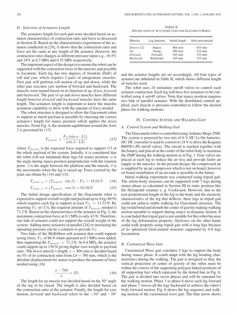
Fig. 13. Fall and recovery test (as in multimedia attachment).
D. Robustness Test
The robustness of the robot was assessed by performing falland recovery experiment from 1 m height stairs as in Fig. 13.The test would result in serious damage for conventional robot;however, the damage to Giacometti robot and its surroundingwas small. The robot is still able to perform basic walking afterminimal recovery during the drop test. This shows the advantageof lightweight property of the robot and the structure.
VI. CONCLUSION
In this letter, a new “Giacometti” concept of robotics wasproposed in which the leg structures are long, light and thin. Gi-acometti robot’s leg mechanism and its model using 4.0 mm softthin McKibben actuators were presented. The muscle lengthsfor stance, swing, forward and backward are based on robotdesign specification using the muscle’s contraction ratio andcontraction force characteristics. The prototype has success-fully demonstrated basic walking using customized Wave gaitand the Giacometti gait with minimum 4 legs to support itsmotion. This work indicated that although Giacometti robotstructure exhibits elastic deformation due to small diameterleg size, the customized Giacometti gait utilizes this structuralflexibility for a unique gait design for its walking capabilityon even and uneven surfaces. The walking gait was discussedwith some parameter changes to see the effect of frequencyand input pressure on the stability of walking motion. Finally,the robustness advantage of the robot was highlighted by al-lowing it to fall from 1 m height stairs. As an extension tothe work, it would be interesting to conduct detail complianceanalysis of the proposed structure and to study the dynamicsof the leg elasticity with more complex control for optimizedgait.
REFERENCES
[1] X. Ding, Z. Wang, A. Rovetta, and J. M. Zhu, “Locomotion analysis ofhexapod robot,” in Climbing and Walking Robots. Rijeka, Croatia: InTech,2010, p. 292.
[2] S. Kitano, “Study of mechanism and control of sprawling-type quadrupedrobot based on intermittent trot Gait,” Ph.D. dissertation, Dept. Mech.Eng., Tokyo Inst. Technol., Tokyo, Japan, 2016.
[3] H. Komatsu, G. Endo, R. Hodoshima, S. Hirose and E. F. Fukushima,“How to optimize the slope walking motion by the quadruped walkingrobot,” Adv. Robot., vol. 29, no. 23, pp. 1497–1509, 2015.
[4] E. P. Krotkov, R. Simmons, W. L. Whittaker, “Ambler: Performance of asix-legged planatery rover,” Acta Astonautica, vol. 35, no. 1, pp. 75–81,1995.
[5] B. H. Wilcox et al., “ATHLETE: A cargo handling and manipulation robotfor the moon,” J. Field Robot., vol. 24, no. 5, pp. 421–434, 2007.
[6] F. Tedeschi and G. Carbone, “Design issues for hexapod walking robots,”J. Robot., vol. 3, pp. 181–206, 2014.
[7] K. Suzumori, “New pneumatic artificial muscle realizing Giacomettirobotics and soft robotics,” in Proc. 6th Int. Conf. Manufact., Mach. DesignTribol., 2015, no. 15–204, pp. 4–5.
[8] M. Takeichi, K. Suzumori, G. Endo, and H. Nabae, “Development ofGiacometti arm with balloon body,” IEEE Robot. Autom., Lett., vol. 2,no. 2, pp. 951–957, Apr. 2017.
[9] G. Galilei, Discorsi e Dimostrazioni Matematiche Intorno a Due NuoveScienze. Amsterdam, Netherlands: Elsevier, 1638.
[10] S. Sakai, K. Osuka, and M. Umeda, “Global performance of agricul-tural robots,” in Proc. IEEE/RSJ Int. Conf. Intell. Robots Syst., 2004,pp. 461–466.
[11] S. M. Levin, “A different approach to the mechanics of the human pelvis:Tensegrity,” Movement, Stability and Low Back Pain, A. Vleeming et al.,Eds. Edinburgh, U.K.: Churchill Livingstone, London, 1997.
[12] http://spectrum.ieee.org/automaton/robotics/diy/inflatable-antroach-robot-is-big-enough-to-ride
[13] U. Mocci, N. Petternella, and S. Salinari, “Experiments with six-leggedwalking machines with fixed gait,” Inst. Autom., Rome Univ., Rome, Italy,Rep. 2-12, 1972.
[14] R. Pinto-da-Rocha, G. Machado, and G. Giribet, HARVESTMAN: TheBiology of Opiliones., Cambridge, MA, USA: Harvard Univ. Press, 2007.
[15] R. Hodoshima, S. Watanabe, Y. Nishiyama, A. Sakaki, Y. Ohura, and S.Kotosaka, “Development of ASURA I: harvestman-like hexapod walkingrobot—approach for Long-legged robot and leg mechanism design,” inProc. IEEE/RSJ Int. Conf. Intell. Robot. Syst., 2013, pp. 4669–4674.
[16] S. Hirose and K. Kato, Study on quadruped walking robot in Tokyoinstitute of technology—past, present and future,” in Proc. IEEE Int. Conf.Robot. Autom., 2000, pp. 1–6.
[17] S. Nakatsu, A. Rosendo, M. Shimizu, and K. Hosoda, “Realization ofthree-dimensional walking of a cheetah-modeled bio-inspired quadrupedrobot,” in Proc. IEEE Int. Conf. Robot. Biomimetics, 2014, pp. 779–784.
[18] T. Kerscher, J. Albiez, and K. Berns, “Joint control of the six-legged robotairbug driven by fluidic muscles,” in Proc. 3rd Int. Workshop Robot MotionControl, 2002, pp. 27–32.
[19] I. N. A. M. Nordin, M. R. M. Razif, A. A. M. Faudzi, E. Natarajan, K.Iwata, and K. Suzumori, “3-D finite-element analysis of fiber-reinforcedsoft bending”, in Proc. IEEE/ASME Int. Conf. Adv. Intell. Mechatronics,2013, pp. 128–133.
[20] A. A. M. Faudzi, N. H. Izzuddin, and K. Suzumori, “Modeling and forcecontrol of thin soft McKibben actuator,” Int. J. Autom. Technol., vol. 10,no. 4, pp. 487–493, 2016.
[21] Y. K. Lee and I. Shimoyama, “A multi-channel micro valve for micropneumatic artificial muscle,” in Proc. IEEE Int. Conf. Micro Electro Mech.Syst., 2002, pp. 702–705.
[22] M. Takaoka, K. Suzumori, S. Wakimoto, S. Iijima, and T. Tokumiya, “Fab-rication of thin McKibben artificial muscle with various design parametersand their experimental evaluations,” in Proc. 5th Int. Conf. Manuf. Mach.Design Tribiol., 2013, pp. 82.
[23] A. A. M. Faudzi, M. R. M. Razif, G. Endo, H. Nabae, and K. Suzumori,“Soft-amphibious robot using thin and soft Mckibben actuator,” in Proc.IEEE Int. Conf. Adv. Intell. Mechatronics, 2017, pp. 981–986.
[24] S. Kurumaya, K. Suzumori, H. Nabae, and S. Wakimoto, “Musculoskeletallower-limb robot driven by multifilament muscles,” Robomech J., vol. 3,no. 18, pp. 1–15, 2016.
[25] R. McNeill Alexender, Principles of Animal Locomotion, Princeton, NJ,USA: Princeton Univ. Press, 2003.
[26] A. A. Biewener, Animal Locomotion. London, U.K.: Oxford Univ. Press,2003.
[27] G. Carbone, “Stiffness analysis and experimental validation of roboticsystems,” Frontiers Mech. Eng., vol. 6, no. 2, pp. 182–196, 2011.