Long Ju Forming of Al 5182-O in a Servo Press at …...Forming of Al 5182-O in a Servo Press at Room...
7
Long Ju School of Mechanical Engineering, University of Science and Technology Beijing, 30 Xueyuan Road, Haidian, Beijing 100083, China e-mail: [email protected] Shrinivas Patil Aida-America Corporation, 7660 Center Point 70 Boulevard, Dayton, OH 45424 e-mail: [email protected] Jim Dykeman Honda R&D Americas, Inc., 21001 State Route 739, Raymond, OH 43067-9705 e-mail: [email protected] Taylan Altan 1 Center for Precision Forming, The Ohio State University, 339 Baker Systems, 1971 Neil Avenue, Columbus, OH 43210 e-mail: [email protected] Forming of Al 5182-O in a Servo Press at Room and Elevated Temperatures Aluminum alloys are increasingly used in automotive manufacturing to save weight. The drawability of Al 5182-O has been proven at room temperature (RT) and it is also shown that formability is further enhanced at elevated temperatures (ETs) in the range of 250–350 C. A cost effective application of ET forming of Al alloys can be achieved using heated blank and cold dies (HB–CD). In this study, the material behavior of Al 5182-O is characterized using tensile test and viscous bulge test at RT. The nonisothermal finite ele- ment model (FEM) of deep drawing is developed using the commercial software PAMSTAMP. Initially, deep drawing simulations and tests were carried out at RT using a 300 ton servo press, with a hydraulic cushion. The predictions with flow stress curves obtained from tensile and bulge tests were compared with experimental data. The effect of punch speed and temperature rise during forming at RT is investigated. The warm forming simulations were carried out by combining material data at ETs obtained from the literature. The coupled effects of sheet temperatures and punch speeds are investi- gated through the finite element analysis (FEA) to provide guidelines for ET stamping of Al 5182-O. [DOI: 10.1115/1.4030334] Keywords: warm forming, aluminum alloy, deep drawing, nonisothermal FEA 1 Introduction The use of aluminum alloys is increasing in automotive stamp- ing, because of aluminum’s low density and high strength to weight ratio. However, stamping of Al alloys presents new chal- lenges in obtaining good part definition and formability at RT. Recent studies have indicated the workability and formability can be increased considerably at ETs [1]. However, this process also has its own challenges, such as heating the blank, controlling the die temperature, lubrication, selection of the appropriate form- ing press, cycle time, and increased cost [2]. Considerable R&D has been conducted in North America in warm forming (around 250–400 C) of “soft” nonage hardenable 5xxx series alloys. Stud- ies covered: determination of material properties, lubrication, FEA, various forming methods such as super plastic forming, quick plastic forming (developed by GM), and development of warm forming cells [3,4]. In a major study conducted by USAMP (U.S. Automotive Materials Partnership), extensive investigations and prototype trials have been conducted in warm forming of Al 5xxx and 6xxx series alloys, mostly on 5754 and 5182. In all these studies, sheet material was formed at around 275 C while the dies were heated in some cases [5] and were kept at RT in most recent studies [4,6]. HB–CD stamping process, with blank heated only, can provide an efficient and economic approach to form Al alloys [7]. Servo presses, having the capability to enable infinitely variable and controllable ram speed and dwell at bottom dead center (BDC), offer a potential improvement in forming quality at both RT and ET [8]. The application of servo presses is continuously increasing in drawing, blanking, and warm forming processes [9]. By using servo presses, the drawability and productivity of deep drawn parts, such as door panels and fenders, were found to be improved with optimized punch speed profiles at RT [10–12]. Regarding to warm drawing of Al–Mg alloys, with specially designed slide motions in a servo press, the blank holder pressure and punch speed were found to have significant effects on heat transfer between interfaces and thickness distribution of the formed part [13]. A number of previous studies have focused on FE simulations of warm forming process by using isothermal and nonisothermal models. Kaya et al. [13] conducted cup drawing simulation of Al sheet forming at ET (25–300 C). The warm forming process of Al 5754-O was simulated using a nonisothermal FEM to study the complex interactions between material properties, temperature, and punch velocity (strain rate). Kim et al. [14] investigated ther- momechanically coupled FEM, which was performed for forming of Al rectangular cups at ETs. The effects of some major factors (i.e., forming speed, blank holder pressure, and friction condition) on forming performance were reviewed and discussed. Abedrabbo et al. [15] developed a temperature-dependent anisotropic material model for use in a coupled thermomechanical FEA of the pure stretch forming of Al 5182 and Al 5754. The failure locations of simulation results at RT and ET matched well with the experiments. The major conclusions of these studies were that (a) due to increased formability Al 5182-O could be successfully warm formed at about 250 C, (b) the cycle time for the operation could be kept to less than 15 s per part, and (c) most importantly, to reduce production costs, it is preferred to use nonheated dies, and provide quick transport of the heated blank from heater into the press, in the forming cell [2]. In this paper, based on previous material characterization and lubricant study, forming of Al 5182-O at both RT and ET is dis- cussed. The nonisothermal FE simulations are carried out using commercial software PAMSTAMP. Deep drawing experiments were performed at RT in a 300 ton servo press. The effects of forming speed at RT were evaluated and presented in detail. HB–CD warm forming was simulated with different blank temperatures and forming speeds. The thickness distribution along critical sec- tions in the formed part was predicted and compared with results at RT. 1 Corresponding author. Contributed by the Manufacturing Engineering Division of ASME for publication in the JOURNAL OF MANUFACTURING SCIENCE AND ENGINEERING. Manuscript received January 8, 2015; final manuscript received March 26, 2015; published online September 4, 2015. Assoc. Editor: Yannis Korkolis. Journal of Manufacturing Science and Engineering OCTOBER 2015, Vol. 137 / 051009-1 Copyright V C 2015 by ASME Downloaded From: http://manufacturingscience.asmedigitalcollection.asme.org/ on 11/20/2015 Terms of Use: http://www.asme.org/about-asme/terms-of-use
Transcript of Long Ju Forming of Al 5182-O in a Servo Press at …...Forming of Al 5182-O in a Servo Press at Room...

Long JuSchool of Mechanical Engineering,
University of Science and Technology Beijing,
30 Xueyuan Road,
Haidian, Beijing 100083, China
e-mail: [email protected]
Shrinivas PatilAida-America Corporation,
7660 Center Point 70 Boulevard,
Dayton, OH 45424
e-mail: [email protected]
Jim DykemanHonda R&D Americas, Inc.,
21001 State Route 739,
Raymond, OH 43067-9705
e-mail: [email protected]
Taylan Altan1
Center for Precision Forming,
The Ohio State University,
339 Baker Systems,
1971 Neil Avenue,
Columbus, OH 43210
e-mail: [email protected]
Forming of Al 5182-O in a ServoPress at Room and ElevatedTemperaturesAluminum alloys are increasingly used in automotive manufacturing to save weight. Thedrawability of Al 5182-O has been proven at room temperature (RT) and it is also shownthat formability is further enhanced at elevated temperatures (ETs) in the range of250–350 �C. A cost effective application of ET forming of Al alloys can be achieved usingheated blank and cold dies (HB–CD). In this study, the material behavior of Al 5182-O ischaracterized using tensile test and viscous bulge test at RT. The nonisothermal finite ele-ment model (FEM) of deep drawing is developed using the commercial softwarePAMSTAMP. Initially, deep drawing simulations and tests were carried out at RT using a300 ton servo press, with a hydraulic cushion. The predictions with flow stress curvesobtained from tensile and bulge tests were compared with experimental data. The effectof punch speed and temperature rise during forming at RT is investigated. The warmforming simulations were carried out by combining material data at ETs obtained fromthe literature. The coupled effects of sheet temperatures and punch speeds are investi-gated through the finite element analysis (FEA) to provide guidelines for ET stamping ofAl 5182-O. [DOI: 10.1115/1.4030334]
Keywords: warm forming, aluminum alloy, deep drawing, nonisothermal FEA
1 Introduction
The use of aluminum alloys is increasing in automotive stamp-ing, because of aluminum’s low density and high strength toweight ratio. However, stamping of Al alloys presents new chal-lenges in obtaining good part definition and formability at RT.
Recent studies have indicated the workability and formabilitycan be increased considerably at ETs [1]. However, this processalso has its own challenges, such as heating the blank, controllingthe die temperature, lubrication, selection of the appropriate form-ing press, cycle time, and increased cost [2]. Considerable R&Dhas been conducted in North America in warm forming (around250–400 �C) of “soft” nonage hardenable 5xxx series alloys. Stud-ies covered: determination of material properties, lubrication,FEA, various forming methods such as super plastic forming,quick plastic forming (developed by GM), and development ofwarm forming cells [3,4]. In a major study conducted by USAMP(U.S. Automotive Materials Partnership), extensive investigationsand prototype trials have been conducted in warm forming ofAl 5xxx and 6xxx series alloys, mostly on 5754 and 5182. In allthese studies, sheet material was formed at around 275 �C whilethe dies were heated in some cases [5] and were kept at RT inmost recent studies [4,6]. HB–CD stamping process, with blankheated only, can provide an efficient and economic approach toform Al alloys [7].
Servo presses, having the capability to enable infinitely variableand controllable ram speed and dwell at bottom dead center(BDC), offer a potential improvement in forming quality at bothRT and ET [8]. The application of servo presses is continuouslyincreasing in drawing, blanking, and warm forming processes [9].By using servo presses, the drawability and productivity of deepdrawn parts, such as door panels and fenders, were found to beimproved with optimized punch speed profiles at RT [10–12].
Regarding to warm drawing of Al–Mg alloys, with speciallydesigned slide motions in a servo press, the blank holder pressureand punch speed were found to have significant effects on heattransfer between interfaces and thickness distribution of theformed part [13].
A number of previous studies have focused on FE simulationsof warm forming process by using isothermal and nonisothermalmodels. Kaya et al. [13] conducted cup drawing simulation of Alsheet forming at ET (25–300 �C). The warm forming process ofAl 5754-O was simulated using a nonisothermal FEM to study thecomplex interactions between material properties, temperature,and punch velocity (strain rate). Kim et al. [14] investigated ther-momechanically coupled FEM, which was performed for formingof Al rectangular cups at ETs. The effects of some major factors(i.e., forming speed, blank holder pressure, and friction condition)on forming performance were reviewed and discussed. Abedrabboet al. [15] developed a temperature-dependent anisotropic materialmodel for use in a coupled thermomechanical FEA of the purestretch forming of Al 5182 and Al 5754. The failure locations ofsimulation results at RT and ET matched well with theexperiments.
The major conclusions of these studies were that (a) due toincreased formability Al 5182-O could be successfully warmformed at about 250 �C, (b) the cycle time for the operation couldbe kept to less than 15 s per part, and (c) most importantly, toreduce production costs, it is preferred to use nonheated dies, andprovide quick transport of the heated blank from heater into thepress, in the forming cell [2].
In this paper, based on previous material characterization andlubricant study, forming of Al 5182-O at both RT and ET is dis-cussed. The nonisothermal FE simulations are carried out usingcommercial software PAMSTAMP. Deep drawing experiments wereperformed at RT in a 300 ton servo press. The effects of formingspeed at RT were evaluated and presented in detail. HB–CDwarm forming was simulated with different blank temperaturesand forming speeds. The thickness distribution along critical sec-tions in the formed part was predicted and compared with resultsat RT.
1Corresponding author.Contributed by the Manufacturing Engineering Division of ASME for publication
in the JOURNAL OF MANUFACTURING SCIENCE AND ENGINEERING. Manuscript receivedJanuary 8, 2015; final manuscript received March 26, 2015; published onlineSeptember 4, 2015. Assoc. Editor: Yannis Korkolis.
Journal of Manufacturing Science and Engineering OCTOBER 2015, Vol. 137 / 051009-1Copyright VC 2015 by ASME
Downloaded From: http://manufacturingscience.asmedigitalcollection.asme.org/ on 11/20/2015 Terms of Use: http://www.asme.org/about-asme/terms-of-use

2 Al Alloy 5182-O Properties
Aluminum alloy 5182-O has an extensive application in auto-motive industry, due to its light weight and good drawability. Thechemical composition and tensile properties of Al 5182-O aregiven in Refs. [15,16].
2.1 Flow Stress at RT—Tensile Test/Bulge Test. The stand-ard uniaxial tensile test is the most widely used method to charac-terize the mechanical properties of engineering materials inindustry [17]. The material properties of Al 5182-O obtained fromtensile test are summarized in Table 1. However, for the FE simu-lation of actual sheet metal forming operations, the tensile test hastwo main limitations: (1) the true strain before instability andnecking is relatively small, and (2) the uniaxial stress state doesnot represent practical forming conditions. Viscous pressure bulge(VPB) test, developed at the Center of Precision Forming, pro-vides higher strain values under biaxial state of stress [18]. Theschematic of VPB test is shown in Fig. 1. The flow stress of thesheet material can be obtained by using inverse FEA, while meas-ured bulge pressure and bulge height are used as inputs. As shownin Fig. 2, with the VPB test, the flow stress of Al 5182-O could beobtained at true strain about 0.5, while tensile test data are avail-able only for strains of 0.2 and must be extrapolated to conductFE simulations.
2.2 Flow Stress at ETs, Effect of Strain Rate. The formabil-ity of Al 5182-O is improved with increasing temperature anddecreasing strain rate under warm forming conditions. The resultsof tensile tests show that temperature and strain rate have almostno effects on the flow stress at temperature range (25–100 �C)[7,15,19]. Thus, the power law can be applied to describe thehardening behavior at this temperature range
r ¼ Ken 25 �C < T � 100 �C (1)
As shown in Fig. 2, based on the bulge test result at RT, thestrength coefficient K and the strain-hardening exponent n are487.6 MPa and 0.263, respectively. However, the flow stress data
obtained from tensile test must be extrapolated to conduct FE sim-ulations. Only the plastic deformation of the data, shown in Fig. 2,can be used in the FE simulation. The elastic portion of the curveis subtracted for this purpose.
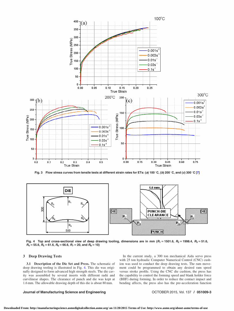
Zhang and Abu-Farha [7] proposed a phenomenological consti-tutive model to describe the plastic deformation of Al 5182-O,with a wide range of temperatures (25–300 �C) and strain rates(0.001–0.1 s�1), as shown in Fig. 3. At temperature range(100–300 �C), the constitutive model is expressed as follows:
r ¼ rpeak �ffiffiffiffiffiffiffiffiffi
aeb�ep
100 �C < T � 300 �C (2)
where a and b were obtained by curve fitting the tensile tests dataat different temperatures and strain rates. The peak stress rpeak isexpressed as a function of Zener–Hollomon factor z
a ¼ 141:14½lnðZÞ�2 � 6301:6 lnðZÞ þ 69623 (3)
b ¼ ð�0:0099T þ 1:5796Þ � ½lnð _eÞ�2 þ ð�0:0977T þ 14:844Þ� lnð _eÞ þ ð�0:1966T � 2:0188Þ (4)
lnðrpeakÞ ¼ �0:5285½lnðZÞ�2 þ 47:808 lnðZÞ � 744:47 (5)
and
Z ¼ _eeðQ=RTÞ (6)
The gas constant R is 8.31 J/mol K and the activation energy Q is142 kJ/mol.
Table 1 Material property of Al 5182-O from tensile test (con-ducted at Honda R&D)
Direction(deg)
Uniform elongation(%)
Yield stress(MPa)
Tensile stress(MPa)
Lankfordvalue
0 21.9 126.9 291.2 0.7145 22.7 121.3 279.8 1.0990 22.0 123.9 285.4 0.84
Fig. 1 Schematic of VPB test [18]: before forming and after forming
Fig. 2 Flow stress curves of Al 5182-O obtained from tensileand VPB tests at RT
051009-2 / Vol. 137, OCTOBER 2015 Transactions of the ASME
Downloaded From: http://manufacturingscience.asmedigitalcollection.asme.org/ on 11/20/2015 Terms of Use: http://www.asme.org/about-asme/terms-of-use
3 Deep Drawing Tests
3.1 Description of the Die Set and Press. The schematic ofdeep drawing tooling is illustrated in Fig. 4. This die was origi-nally designed to form advanced high strength steels. The die cav-ity was assembled by several inserts with different radii andcurvilinear shapes. The clearance of punch and die was kept at1.6 mm. The allowable drawing depth of this die is about 80 mm.
In the current study, a 300 ton mechanical Aida servo presswith 25 ton hydraulic Computer Numerical Control (CNC) cush-ion was used to conduct the deep drawing tests. The ram move-ment could be programmed to obtain any desired ram speedversus stroke profile. Using the CNC die cushion, the press hasthe capability to control the forming speed and blank holder force(BHF) during forming. In order to reduce the contact impact andbending affects, the press also has the pre-acceleration function
Fig. 3 Flow stress curves from tensile tests at different strain rates for ETs: (a) 100 �C, (b) 200 �C, and (c) 300 �C [7]
Fig. 4 Top and cross-sectional view of deep drawing tooling, dimensions are in mm (R1 5 1501.6, R2 5 1998.4, R3 5 51.6,R4 5 55.6, R5 5 61.6, R6 5 66.6, R7 5 20, and R8 5 10)
Journal of Manufacturing Science and Engineering OCTOBER 2015, Vol. 137 / 051009-3
Downloaded From: http://manufacturingscience.asmedigitalcollection.asme.org/ on 11/20/2015 Terms of Use: http://www.asme.org/about-asme/terms-of-use

with several levels (strong, medium, and weak). The data mea-surement system of the press can record positions, speeds, andload data for the punch and die cushion.
Two types of speed profiles are analyzed, including (1)mechanical crank motion (1 SPM, 10 SPM, and 18 SPM) and (2)constant speed during deformation (50 mm/s and 310 mm/s). Asseen in Fig. 5, the mechanical crank motion is a basic sine curve.However, for constant speed profile, the ram speed could not bekept constant during the whole forming stroke, because at a certainstroke position it is necessary for the slide to decelerate to the BDC.
3.2 Evaluation and Selection of Lubricants for RTForming. In a previous study, the performances of 14 lubricants,including oil based, water based, and dry film lubricants, wereevaluated by using cup drawing test. The Al 5182-O sheets wereavailable with two different surface textures, including mill finishand electrodischarge texturing (EDT). The performance of the
lubricants was determined by measuring (1) maximum applicableBHF for cup drawing without defects, and (2) the draw-in lengthor the flange perimeter of formed cups at each BHF. As illustratedin Fig. 6, it was found that dry film lubricants performed better indeep drawing of 5182-O with EDT surface texturing.
4 FEM of the Deep Drawing Operation
In order to understand the complex interactions between mate-rial behavior, friction conditions, and temperature effects on deepdrawing of Al alloys at both RT and ET, it is necessary to analyzethe process using a nonisothermal FEM. In the current study, thenonisothermal FEM was developed using commercial softwarePAMSTAMP, as illustrated in Fig. 7(a). The sheet, with 1.2 mm thick-ness, is designed with rectangular shape (720 mm� 500 mm) withchamfered corners, as shown in Fig. 7(b). Four-node shell ele-ments were used to simulate the deformation and heat transfer.The tools are considered as rigid bodies with 6 mm thermal thick-ness, to enable the calculation of temperature gradient. Initial tem-perature of the tools is assumed to be 25 �C, while the sheet willbe assumed to be heated to various initial temperatures rangingfrom 25 �C to 300 �C. In the FEM, Eqs. (1) and (2) are used todefine the flow stress at temperature ranges 25–100 �C and100–300 �C, respectively. The heat transfer coefficient (HTC)varying with contact pressure (Fig. 8) is applied between the con-tact interfaces [20]. The thermal–mechanical properties and simu-lation inputs are summarized in Table 2.
5 Results and Discussion
5.1 Validation of the FEMs at RT. Figure 9(a) shows thepart drawn to 75 mm under BHF 150 kN at a forming speed of18 SPM. In order to investigate the input flow stress curves on theaccuracy of FE predictions, the data obtained from tensile test andVBP test (Fig. 2) were used in the simulations, respectively. Theload–stroke curve and thinning distribution along the criticalselected corner section, obtained in experiments, were measuredand compared with predicted results.
As shown in Fig. 9(b), by using COF 0.1, the predictedload–stroke curves with tensile test data and VPB test data can
Fig. 5 Ram speed profiles with crank motion (1 SPM, 10 SPM,and 18 SPM) and nearly constant (50 mm/s and 310 mm/s)punch speed during deformation (Aida 300 ton servo press)
Fig. 6 Flange perimeters measured from formed cups with var-ious lubricants at BHF 16 ton
Fig. 7 (a) 3D FEM of deep drawing process and (b) blank dimensions (mm)
Fig. 8 Variation of HTC with contact pressure [20]
051009-4 / Vol. 137, OCTOBER 2015 Transactions of the ASME
Downloaded From: http://manufacturingscience.asmedigitalcollection.asme.org/ on 11/20/2015 Terms of Use: http://www.asme.org/about-asme/terms-of-use

both give a good match with the experimental result. As seen inFig. 10(b), more accurate thickness variation was predicted withVPB test data for COF 0.1.
5.2 Effect of Forming Speed at RT. Deep drawing testswere conducted at various punch speeds. The speed profiles areillustrated in Fig. 5. The sheet samples were precoated with dryfilm lubricant. The forming stroke was set to 60.8 mm and BHFwas 125 kN. The test results at 50 mm/s and 310 mm/s are shownin Fig. 11. Due to the convex shape and the smaller corner radius(R5 shown in Fig. 4), the cracks always initially occurred at thelower right corner (Fig. 11(a)). It was found that the part could beformed without cracks when applying a higher ram speed(310 mm/s), as shown in Fig. 11(b).
Figure 12 illustrates the punch load for various ram speedsmentioned above. It is seen that the load drop during deformation
Table 2 Input parameters of the nonisothermal FEMs
PropertyB¼ blank, D¼ dies, and P¼ press Description
B—flow stress curve Tensile/VPB test data at RT (Fig. 2)Tensile test data at ET (Fig. 3)
B—Young’s modulus (E) 70.6 GPaB—Poisson ratio (t) 0.341B—sheet temperature (Ts) 25/100/200/300 �CD—thermal conductivity (k) 130 W/m CD—specific heat capacity (C) 900 J/kg CD—coefficient of friction (COF) 0.08–0.12D—die temperature (Tt) 25 �CP—BHF Max. 250 kNP—stroke (s) Max. 80 mmP—ram speed (�) As shown in Fig. 5
Fig. 9 Test results and predicted punch force at RT: (a) formed part and (b) comparison of punch forcesbetween experiment and FEM
Fig. 10 Comparison of thickness variations: (a) selected corner sections A–D and (b) thinningvariations from experiment and FE simulations
Fig. 11 Results of deep drawing tests with a dry film lubricantunder different forming speeds at RT, stroke 60.8 mm: (a)50 mm/s, crack at lower right corner and (b) 310 mm/s, defectfree formed part
Fig. 12 Experimental and predicted load–stroke curves atforming speeds 50 mm/s and 310 mm/s
Journal of Manufacturing Science and Engineering OCTOBER 2015, Vol. 137 / 051009-5
Downloaded From: http://manufacturingscience.asmedigitalcollection.asme.org/ on 11/20/2015 Terms of Use: http://www.asme.org/about-asme/terms-of-use

is observed at forming speed of 50 mm/s, which indicates theoccurrence of fracture. In this case, the maximum draw depth isapproximately 53.6 mm at 50 mm/s punch speed. It is also seen inFig. 12 that the maximum punch load decreases with increasingforming speed. By using COF 0.12 and 0.1 in the FEM, the pre-dicted stroke–load curves show a good match with the experimen-tal results at 50 mm/s and 310 mm/s, respectively. It can be seenthat the friction condition in the contact interfaces may changewith different forming speeds at RT. This observation is subjectof ongoing study by the authors.
5.3 Prediction of Temperature Distribution During Formingat RT. During forming, plastic deformation and friction causetemperature increases in the part as well as at the die and punchsurface. The proposed nonisothermal FEM was able to predictthese temperature distributions. Figure 13 shows the predictednodal temperature distribution in the deformed part. The highertemperature is found around the die-shoulder corners, where mate-rial flows under high contact pressure and friction work. SectionsE–J (Fig. 13) are selected to evaluate the effect of forming speedon the temperature distributions. As illustrated in Fig. 14, thepunch maximum temperatures are 77.3 �C at 310 mm/s, 52 �C at50 mm/s, and 34.8 �C at 10 mm/s and they are at location I. In thedrawing tests, the temperature rise on the drawn part was moder-ate and probably not too severe to change the performance of thelubricant during the tests.
The highest temperatures 27 �C and 32 �C were predicted in thepunch and die, respectively, at forming speed of 310 mm/s. Thepeak temperature in the die occurred at the corner regions. How-ever, it was found that the location of peak temperature in thepunch moved from the corner to the wall with forming stroke. Itshould be noted, however, that the estimated temperatures are forone stroke operation only. Under production conditions, when
10–20 parts per minute are formed, the die temperatures will behigher.
5.4 Deep Drawing at ET Using HB–CD. Using the constitu-tive model proposed by Zhang and Abu-Farha [7], ET formingsimulations were carried out with heated 5182-O sheets at temper-atures 100 �C, 200 �C, and 300 �C, while the initial temperature ofthe tools is set to 25 �C (RT). Figure 15 shows the effect of sheetinitial temperature on the thinning distribution in the selected cor-ner with constant forming speed 310 mm/s. It can be noted thatthere was almost no difference in thinning distribution at 100 �Ccompared parts formed at RT (Fig. 10(b)) and the maximum thin-ning in the drawn part occurred around punch corner (location Bin Fig. 10(a)). However, at ET forming, as the heated blank con-tacts the cold punch, a lower temperature gradient was establishedin the deformed part around the punch corner, where the materialhas greater strain hardening than hotter wall area. From Fig. 15, itcan be seen that the maximum thinning values 12.8% and 15.4%at 200 �C and 300 �C, respectively, occurred on the wall (betweenB and C) instead of corner area.
Further simulations were carried out to evaluate the part qualityat different forming speeds 50 mm/s and 310 mm/s (initial blanktemperature 200 �C) under ET forming conditions. With a higherforming speed, the part is deformed under higher strain rate; thusthe material is stronger due to increased strain rate hardeningeffect. However, as illustrated in Fig. 16, it is found that moreuniform thickness distribution could be achieved at 50 mm/s.Figure 17 shows the predicted temperature distributions in thedeformed part at forming speeds 50 mm/s and 310 mm/s with thesame initial blank temperature (200 �C). The temperature decreaseis approximately 80 �C in the part corner regions when forming at50 mm/s. It should be noted that lower ram speed provided moretime for interface heat transfer between the heated sheet and thedies. As a result, the plastic behavior was locally affected by dif-ferent temperature gradient across the part during deformation.
Fig. 13 Estimated temperature distribution in the drawn part atforming speed 310 mm/s, stroke 5 60 mm
Fig. 14 Predicted temperature distributions in the drawn partalong the selected sections E–J (Fig. 13) at different formingspeeds, stroke 5 60 mm
Fig. 15 The effect of initial sheet temperature on the thinningdistribution in the part corner, forming speed 310 mm/s, punchstroke 75 mm (locations A, B, C, and D are shown in Fig. 10(a))
Fig. 16 The effect of forming speed on the thickness distribu-tion in the part corner, initial sheet temperature 200 �C, punchstroke 75 mm (simulation)
051009-6 / Vol. 137, OCTOBER 2015 Transactions of the ASME
Downloaded From: http://manufacturingscience.asmedigitalcollection.asme.org/ on 11/20/2015 Terms of Use: http://www.asme.org/about-asme/terms-of-use

Although forming at low speed is not efficient and leads to greaterheat loss, better part quality could be achieved by combinedeffects of sheet temperature and punch speed at ET forming con-dition. However, the variability in temperature and thickness dis-tributions in the manufactured parts could be obvious in stampingcycles. More investigations, such as lubrication, die temperaturecontrol in mass production, and process optimization, are neces-sary for the application of the proposed process under productionconditions.
6 Summary and Conclusions
The drawability of aluminum alloy 5182-O under cold andwarm conditions was discussed in detail. The material behavior ischaracterized using tensile test and viscous bulge test at RT. Byutilizing the 300 ton servo press, the deep drawing tests were con-ducted at different forming speeds at RT. The nonisothermal FEMwas developed to help analyze the drawing process at RT, includ-ing experiment design, model validation, friction investigation,and temperature prediction. In addition, a more detailed under-standing of the warm forming process (with sheet heated only)was provided by utilizing the nonisothermal simulation analysis.The effects of temperature and punch speed were investigated.Following conclusions can be drawn from this study:
(1) Regarding material testing methods, comparing to tensiletest, VPB test could provide a more accurate prediction ofthickness distribution across the critical corner section inthe drawn part. However, a good match in load–strokecurves could be achieved with both flow stress data byusing a proper coefficient of friction.
(2) The effect of forming speed on the part drawability is foundto be significant at RT. Results indicated that the better partquality could be achieved with a higher forming speed,which could also be considered in production for a moreefficient process. By using the nonisothermal FEM, thepeak temperature rise was predicted to be 73 �C in thedrawn part around die should at the highest forming speed310 mm/s. However, in the single stroke condition studiedhere, there was no significant temperature rise in the dieand punch.
(3) Temperature gradient is found to have a great effect on thethickness distribution of the drawn part under warm form-ing conditions. The maximum thinning was predicted tooccur in the wall when forming at 200 �C and 300 �C, whileit was found to be in the corner area under cold formingcondition (25–100 �C). The combined effects of tempera-ture and punch speed could help to obtain a better thicknessdistribution in the deformed part under warm formingconditions.
Acknowledgment
The authors would like to extend special thanks to the membercompanies of the Center of Precision Forming (CPF) that funded
this study. Special thanks are due to Shiloh Industries, Inc. (CliffHoschouer) and Honda Engineering (Dennis O’Connor) for sup-porting this project.
References[1] Toros, S., Ozturk, F., and Kacar, I., 2008, “Review of Warm Forming
of Aluminum–Magnesium Alloys,” J. Mater. Process. Technol., 207(1), pp.1–12.
[2] Billur, E., and Altan, T., 2013, “Warm Forming of Alloys in the Auto Industry,”Stamping J., pp. 20–25.
[3] Carsley, J., Krajewski, P., Schroth, J., and Lee, T., 2006, “Aluminum FormingTechnologies: Status and Research Opportunities,” New Developments in SheetMetal Forming International Conference, IFU, Stuttgart, Germany.
[4] Harrison, N. R., 2012, “Optimization of High-Volume Warm Forming forLightweight Sheet Alloys,” AMD 905, DOE-USAMP Cooperative AgreementNo. DE-FC26-020R22910.
[5] Friedman, P. A., 2009, “AMD 602 Final Report—Development of High-Volume Warm Forming of Low-Cost Magnesium Sheet,” DOE-USAMP Coop-erative Agreement No. DE-FC05-020R22910.
[6] Harrison, N. R., Ilinich, A., Friedman, P. A., Singh, J., and Verma, R., 2013,“Optimization of High-Volume Warm Forming for Lightweight Sheet,” SAETechnical Paper No. 2013-01-1170.
[7] Zhang, N., and Abu-Farha, F., 2015, “Characterizing and Modeling the Defor-mation of AA5182 for Hot Blank–Cold Die (HB-CD) Stamping,” 144th TMSAnnual Meeting and Exhibition (TMS 2015), Orlando, FL, Mar. 15–19, pp.315–320.
[8] Osakada, K., Mori, K., Altan, T., and Groche, P., 2011, “Mechanical ServoPress Technology for Metal Forming,” CIRP Ann.-Manuf. Technol., 60(2), pp.651–672.
[9] Altan, T., and Groseclose, A., 2009, “Servo-Drive Presses-Recent Devel-opments,” Umformtechnisches Kolloqium Darmstadt, 10.
[10] Hayashi, H., and Nishimura, H., 2009, “The Application of Servo PressMachine to Forming of Sheet Metals With Low Formability,” Ann. “DunareaJos” Univ. Galati Fasc. V: Technol. Mach. Build., pp. 3–10.
[11] Groche, P., and M€oller, N., 2012, “Tribological Investigation of Deep-DrawingProcesses Using Servo Presses,” ASME Paper No. MSEC2012-7292.
[12] Taoka, H., Mawari, H., Higashi, H., Ikehara, H., Hashimoto, M., and Kawano,Y., 2009, “Development of the World’s Fastest Servo Press Line forManufacturing Automotive Body Panels,” Mater. Process. Technol., 50(12), pp.33–38.
[13] Kaya, S., Spampinato, G., and Altan, T., 2008, “An Experimental Study onNonisothermal Deep Drawing Process Using Aluminum and MagnesiumAlloys,” ASME J. Manuf. Sci. Eng., 130(6), p. 061001.
[14] Kim, H. S., Koc, M., Ni, J., and Ghosh, A., 2006, “Finite Element Modelingand Analysis of Warm Forming of Aluminum Alloys—Validation ThroughComparisons With Experiments and Determination of a Failure Criterion,”ASME J. Manuf. Sci. Eng., 128(3), pp. 613–621.
[15] Abedrabbo, N., Pourboghrat, F., and Carsley, J., 2007, “Forming of AA5182-Oand AA5754-O at Elevated Temperatures Using Coupled Thermo-MechanicalFinite Element Models,” Int. J. Plast., 23(5), pp. 841–875.
[16] Li, J., Hu, S. J., Carsley, J. E., Lee, T. M., Hector, L. G., and Mishra, S., 2011,“Postanneal Mechanical Properties of Prestrained AA5182-O Sheets,” ASME J.Manuf. Sci. Eng., 133(6), p. 061007.
[17] Altan, T., and Tekkaya, A. E., eds., 2012, Sheet Metal Forming: Processes andApplications, ASM International, Materials Park, OH.
[18] Nasser, A., Yadav, A., Pathak, P., and Altan, T., 2010, “Determination ofthe Flow Stress of Five AHSS Sheet Materials (DP 600, DP 780, DP 780-CR,DP 780-HY and TRIP 780) Using the Uniaxial Tensile and the Biaxial Vis-cous Pressure Bulge (VPB) Tests,” J. Mater. Process. Technol., 210(3), pp.429–436.
[19] Picu, R. C., Vincze, G., Ozturk, F., Gracio, J. J., Barlat, F., and Maniatty, A.M., 2005, “Strain Rate Sensitivity of the Commercial Aluminum AlloyAA5182-O,” Mater. Sci. Eng., A, 390(1), pp. 334–343.
[20] Billur, E., 2013, “Fundamentals and Applications of Hot Stamping Technologyfor Producing Crash-Relevant Automotive Parts,” Ph.D. thesis, The Ohio StateUniversity, Columbus, OH.
Fig. 17 Temperature distribution in the part under forming speed: (a) 50 mm/s and (b) 310 mm/s,initial sheet temperature 200 �C, punch stroke 75 mm (simulation)
Journal of Manufacturing Science and Engineering OCTOBER 2015, Vol. 137 / 051009-7
Downloaded From: http://manufacturingscience.asmedigitalcollection.asme.org/ on 11/20/2015 Terms of Use: http://www.asme.org/about-asme/terms-of-use