
LogiCORE IP Convolutional Encoder v8 - Xilinx · Convolutional Encoder v8.0 4 PG026 January 18,...
23
LogiCORE IP Convolutional Encoder v8.0 Product Guide PG026 January 18, 2012
Transcript of LogiCORE IP Convolutional Encoder v8 - Xilinx · Convolutional Encoder v8.0 4 PG026 January 18,...

LogiCORE IP Convolutional Encoder v8.0Product Guide
PG026 January 18, 2012

Convolutional Encoder v8.0 www.xilinx.com 1PG026 January 18, 2012
Chapter 1: OverviewStandards Compliance . . . . . . . . . . . . . . . . . . . . . . . . . . . . . . . . . . . . . . . . . . . . . . . . . . . . . . . 4Performance . . . . . . . . . . . . . . . . . . . . . . . . . . . . . . . . . . . . . . . . . . . . . . . . . . . . . . . . . . . . . . . . . 4Resource Utilization. . . . . . . . . . . . . . . . . . . . . . . . . . . . . . . . . . . . . . . . . . . . . . . . . . . . . . . . . . 5
Chapter 2: Core InterfacesPort Descriptions. . . . . . . . . . . . . . . . . . . . . . . . . . . . . . . . . . . . . . . . . . . . . . . . . . . . . . . . . . . . . 6
Chapter 3: Customizing and Generating the CoreCORE Generator GUI and Parameters . . . . . . . . . . . . . . . . . . . . . . . . . . . . . . . . . . . . . . . 11Parameter Values in the XCO File . . . . . . . . . . . . . . . . . . . . . . . . . . . . . . . . . . . . . . . . . . . 13Output Generation . . . . . . . . . . . . . . . . . . . . . . . . . . . . . . . . . . . . . . . . . . . . . . . . . . . . . . . . . . 13
Chapter 4: Designing with the CorePuncturing . . . . . . . . . . . . . . . . . . . . . . . . . . . . . . . . . . . . . . . . . . . . . . . . . . . . . . . . . . . . . . . . . . 14AXI4-Stream Protocol . . . . . . . . . . . . . . . . . . . . . . . . . . . . . . . . . . . . . . . . . . . . . . . . . . . . . . . 15
Chapter 5: Detailed Example DesignDemonstration Test Bench . . . . . . . . . . . . . . . . . . . . . . . . . . . . . . . . . . . . . . . . . . . . . . . . . . 17System Generator for DSP Graphical User Interface . . . . . . . . . . . . . . . . . . . . . . . . . 18
Appendix 6: MigratingParameter Changes in the XCO File. . . . . . . . . . . . . . . . . . . . . . . . . . . . . . . . . . . . . . . . . . 19Port Changes . . . . . . . . . . . . . . . . . . . . . . . . . . . . . . . . . . . . . . . . . . . . . . . . . . . . . . . . . . . . . . . . 20
Appendix 7: Additional ResourcesXilinx Resources . . . . . . . . . . . . . . . . . . . . . . . . . . . . . . . . . . . . . . . . . . . . . . . . . . . . . . . . . . . . 21Solution Centers . . . . . . . . . . . . . . . . . . . . . . . . . . . . . . . . . . . . . . . . . . . . . . . . . . . . . . . . . . . . 21References . . . . . . . . . . . . . . . . . . . . . . . . . . . . . . . . . . . . . . . . . . . . . . . . . . . . . . . . . . . . . . . . . . 21Technical Support. . . . . . . . . . . . . . . . . . . . . . . . . . . . . . . . . . . . . . . . . . . . . . . . . . . . . . . . . . . 21Ordering Information . . . . . . . . . . . . . . . . . . . . . . . . . . . . . . . . . . . . . . . . . . . . . . . . . . . . . . . 22Revision History . . . . . . . . . . . . . . . . . . . . . . . . . . . . . . . . . . . . . . . . . . . . . . . . . . . . . . . . . . . . 22Notice of Disclaimer . . . . . . . . . . . . . . . . . . . . . . . . . . . . . . . . . . . . . . . . . . . . . . . . . . . . . . . . 22
Table of Contents

Convolutional Encoder v8.0 www.xilinx.com 3PG026 January 18, 2012 Product Specification
IntroductionThe Convolution Encoder core can be used in a widevariety of error correcting applications and is typicallyused in conjunction with the Viterbi Decoder [Ref 4].
Features• High-speed compact convolution encoder with
puncturing option
• Parameterizable constraint length from 3 to 9
• Parameterizable convolution codes
• Parameterizable puncture codes
• Puncturing rates from 2/3 to 12/23 available
• For use with Xilinx® CORE Generator™ Version 13.4
LogiCORE IP ConvolutionalEncoder v8.0
LogiCORE™ IP Facts Table
Core Specifics
Supported Device Family(1)
Virtex®-7, Kintex™-7, Artix™-7, Zynq™-7000,Virtex-6, Spartan®-6
Supported User Interfaces AXI4-Stream
Resources See Table 1-2.
Provided with Core
Design Files Product Guide
Example Design Not provided.
Test Bench See Demonstration Test Bench.
Constraints File N/A
Simulation Model
VHDL behavioral model in the xilinxcorelib libraryVHDL UNISIM structural model
Verilog UNISIM structural model
Supported S/W Driver(2) N/A
Tested Design Tools
Design Entry Tools
CORE Generator tool 13.4System Generator for DSP 13.4
Simulation(3)
Mentor Graphics ModelSimCadence Incisive Enterprise Simulator (IES)
Synopsys VCS and VCS MXISim
Synthesis Tools(3) N/A
Support
Provided by Xilinx @ www.xilinx.com/support
1. For a complete listing of supported devices, see the release notes for this core.
2. Standalone driver details can be found in the EDK or SDK directory (<install_directory>/doc/usenglish/xilinx_drivers.htm). Linux OS and driver support information is available from http://wiki.xilinx.com.
3. For the supported versions of the tools, see the ISE Design Suite 13: Release Notes Guide.

Convolutional Encoder v8.0 www.xilinx.com 4PG026 January 18, 2012 Product Specification
Chapter 1
Overview
The basic architecture of the Convolutional Encoder core is shown in Figure 1-1. The incoming data is brought into the constraint register a bit at a time, and the output bits are generated by modulo-2 addition of the required bits from the constraint register. The bits to be XOR’d are selected by the convolution codes as shown in Figure 1-1.
Convolution encoding is used to encode data prior to transmission over a channel. The received data is decoded by the classic Viterbi decoder. In a basic convolution encoder, two or three bits (depending on the encoder output rate) are transmitted over the channel for every input bit.
Standards ComplianceThe Convolution Encoder IP core adheres to the AMBA® AXI4-Stream standard [Ref 2].
Performance
LatencyFor this core, latency is defined as the number of rising clock edges from sampling S_DATA to the sampled value appearing on M_DATA. The latency varies with the puncture type and puncture rate. See Table 1-1 for some example latency figures.
X-Ref Target - Figure 1-1
Figure 1-1: Convolution Encoder Constraint Length 9

Convolutional Encoder v8.0 www.xilinx.com 5PG026 January 18, 2012 Product Specification
Chapter 1: Overview
ThroughputThe maximum raw data input rate in Mb/s can be calculated as Fmax(MHz) for non-punctured and dual decoder and Fmax(MHz) * n/m for the punctured non-dual decoder where n is the input rate and m is the output rate of the punctured core.
Resource UtilizationThe area of the core increases with the constraint length and the punctured input andoutput rates if the core is punctured. Some example configurations are shown in Table 1-2.
Table 1-1: Latency
Convolution Encoder Type Latency
Non Puncture 3
Punctured dual rate 3/4 15
Punctured non-dual rate 3/4 10
Table 1-2: Examples of Convolution Encoder Implementations on Spartan-6 FPGAs
Rate 1/2 Rate 3/4 Rate 5/6 Rate 12/23
Constraint Length 7 7 7 7
Xilinx Part XC6SLX45T XC6SLX45T XC6SLX45T XC6SLX45T
LUT/FF Pairs 25 61 67 128
Maximum Clock Frequency(1)(2) 374 374 359 320
Notes: 1. Area and maximum clock frequencies are provided as a guide. They can vary with new releases of the
Xilinx implementation tools.2. Maximum clock frequencies are shown in MHz for -2 parts. Clock frequency does not take jitter into
account and should be de-rated by an amount appropriate to the clock source jitter specification.

Convolutional Encoder v8.0 www.xilinx.com 6PG026 January 18, 2012
Chapter 2
Core Interfaces
This chapter provides detailed descriptions for each interface.
Port DescriptionsSymbols for the core with the AXI channels are shown in Figure 2-1 and Figure 2-2.
Table 2-1 summarizes the signal functions. They are described in more detail in the remain-der of this section. Timing diagrams for the signals are shown throughout this section.
X-Ref Target - Figure 2-1
Figure 2-1: Core AXI Channels
X-Ref Target - Figure 2-2
Figure 2-2: Core Schematic Symbol

Convolutional Encoder v8.0 www.xilinx.com 7PG026 January 18, 2012
Chapter 2: Core Interfaces
aclkenThe clock enable input (aclken) is an optional pin. When aclken is deasserted (low), all the other synchronous inputs are ignored, except aresetn, and the core remains in its current state. This pin should be used only if it is genuinely required because it has a high fan out within the core and can result in lower performance. aclken is a true clock enable and causes the entire core to freeze state when it is low.
An example of aclken operation is shown in Figure 2-3. In this case, the core ignores symbol D4 as input to the block, and the current m_axis_data_tdata value remains unchanged.
Table 2-1: Core Signal Pinout
Signal Direction Description
aclk Input Rising edge clock
aclken Input Active high clock enable (optional)
aresetn Input Active low synchronous clear (overrides aclken)
s_axis_data_tdata Input Input data
s_axis_data_tvalid Input tvalid for S_AXIS_DATA channel. See aclken for protocol.
s_axis_data_tlast InputMarks last symbol of input block. Only used to generate event outputs. Can be tied low or high if event outputs not used.
s_axis_data_tready Output
tready for S_AXIS_DATA. Indicates that the core is ready to accept data. Always high, except after a reset, in the non punctured and Dual Output core if there is not a tready on the output.
m_axis_data_tdata Output
tdata for the output data channel, convolutionally encoded data output in parallel for the non punctured and Dual Output case. Serial output for the punctured non-dual case.
m_axis_data_tvalid Output tvalid for M_AXIS_DATA channel
m_axis_data_tlast Outputtlast for the output data channel, indicates the last element in the punctured group.
m_axis_data_tready Inputtready for M_AXIS_DATA channel. Tie high if downstream slave is always able to accept data from M_AXIS_DATA
event_s_data_tlast_missing OutputFlags that s_axis_data_tlast was not asserted when expected. Leave unconnected if not required.
event_s_data_tlast_unexpected Output Flags that s_axis_data_tlast was asserted when not expected. Leave unconnected if not required.
All AXI4-Stream port names are lower case, but for ease of visualization, upper case is used in this document when referring to port name suffixes, such as tdata or tlast.

Convolutional Encoder v8.0 www.xilinx.com 8PG026 January 18, 2012
Chapter 2: Core Interfaces
aresetnThe synchronous reset (aresetn) input can be used to re-initialize the core at any time, regardless of the state of aclken. aresetn needs to be asserted low for at least two clock cycles to initialize the circuit. The core becomes ready for normal operation two cycles after aresetn goes high if aclken is high. The timing for the aresetn input is shown in Figure 2-4.
S_AXIS_DATA Channel
s_axis_data_tdata
Data to be processed is passed into the core on this port. To ease interoperability with byte-oriented buses, tdata is padded with zeros, for the convolutional encoder the bus is always 8 bits. The padding bits are ignored by the core and do not result in additional resource use. The structure is shown in Figure 2-5.
X-Ref Target - Figure 2-3
Figure 2-3: Clock Enable Timing
aclk
aclken
s_axis_data_tvalid
s_axis_data_tdata
m_axis_data_tdata
D0 D1 D2 D3 D4 D5 D6
X-Ref Target - Figure 2-4
Figure 2-4: Synchronous Reset Timing
aclk
aclken
aresetn
sclr_i
s_axis_data_tready
X-Ref Target - Figure 2-5
Figure 2-5: Input Channel TDATA Structure

Convolutional Encoder v8.0 www.xilinx.com 9PG026 January 18, 2012
Chapter 2: Core Interfaces
DATA_IN Field
This is the input bit for the incoming data. The width of the DATA_IN field is always 1.
s_axis_data_tlast
This input can be tied low or high if the event outputs (event_s_data_tlast_missing and event_s_data_tlast_unexpected) are not used. It is present purely to provide a check that the system and core are in sync with the applied puncturing. If the event outputs are used then s_axis_data_tlast must be asserted high when the last symbol of a punctured group is sampled on s_axis_data_tdata. The core maintains its own internal count of the symbols, so it knows when the last symbol is being sampled. If s_axis_data_tlast is not sampled high when the last input symbol is sampled then event_s_data_tlast_missing is asserted until the next input sample is taken. Similarly, if s_axis_data_tlast is sampled high when the core is not expecting it, event_s_data_tlast_unexpected is asserted until the next input sample is taken. If either of these events occurs then the system and the core are out of sync and the core, and possibly the system, should be reset.
Single-Channel Output
For the single-channel output, after n input bits (puncture input rate) have been received, the tready signal goes low for m-n (where m is the puncture output rate) clock periods. The m_axis_data_tvalid signal is used to indicate that valid output data is available which is output in a block of m bits (puncture output rate), as shown in Figure 2-8.
Dual-Channel Output
For the dual-channel punctured case, s_axis_data_tready is always high (unless aresetn has been asserted or back pressure has been applied). The dual channel puncturing works on two blocks of n bits of data. After 2n input bits have been received, where n is the punctured input rate, m symbols are output on m_axis_data_tdata (width 2) after a certain latency. The m_axis_data_tvalid signal indicates the valid outputs. The data is output in blocks of m symbols (width 2) and the m_axis_data_tvalid signal is high for m clock cycles and low for the next 2n-m. See Figure 2-7 for the 3/4 rate dual-channel punctured encoder.
M_AXIS_DATA Channel
m_axis_data_tdata
Uncoded data sampled on s_axis_data_tdata is encoded and output from the core on this port. All output data is padded with zeroes to fit a bit field which is always 8 bits. The structure is shown in Figure 2-6.X-Ref Target - Figure 2-6
Figure 2-6: Output Data Channel TDATA Structure

Convolutional Encoder v8.0 www.xilinx.com 10PG026 January 18, 2012
Chapter 2: Core Interfaces
DATA_OUT Field
This is the output field for the encoded bits. The width depends on the type of encoder. For the case of unpunctured data the width is equal to the output rate. For punctured data with serial output the width is 1 bit and for the dual channel encoder the output width is 2 bits. Corrected symbols start to appear a number of clock cycles after the first symbol is sampled on DATA_IN.
m_axis_data_tlast
This output is high when the last data_out of a punctured block is on m_axis_data_tdata. The port is not present on the non-punctured core. In the dual output case, m_axis_data_tlast is only asserted high when m output pairs have been output, this corresponds to 2n data inputs. This is shown in Figure 2-7. For the serial case the signal is asserted when m serial outputs have been output.This is shown in Figure 2-8.
X-Ref Target - Figure 2-7
Figure 2-7: Dual Output Timing for Rate 3/4 Puncturing
aclk
s_axis_data_tvalid
s_axis_data_tready
s_axis_data_tdata
s_axis_data_tlast
m_axis_data_tvalid
m_axis_data_tready
m_axis_data_tdata
m_axis_data_tlast
Di0 Di1 Di2 Di3 Di4 Di5 Di6 Di7
Do0 Do1 Do2 Do3
X-Ref Target - Figure 2-8
Figure 2-8: Serial Output Timing for Rate 3/4 Puncturing
aclk
s_axis_data_tvalid
s_axis_data_tready
s_axis_data_tdata
s_axis_data_tlast
m_axis_data_tvalid
m_axis_data_tready
m_axis_data_tdata
m_axis_data_tlast
Di0 Di1 Di2 Di3 Di4 Di5
Do0 Do1 Do2 Do3 Do4 Do5 Do6

Convolutional Encoder v8.0 www.xilinx.com 11PG026 January 18, 2012
Chapter 3
Customizing and Generating the Core
This chapter includes information on using Xilinx® tools to customize and generate the core.
CORE Generator GUI and ParametersFigure 3-1 illustrates the main CORE Generator™ screen. Each parameter is defined in thefollowing sections. To generate a core, click Generate.
Component NameThe component name is used as the base name of the output files generated for the core.Names must begin with a letter and must be composed from the following characters: a toz, 0 to 9 and “_”.
X-Ref Target - Figure 3-1
Figure 3-1: Convolution Encoder Graphical User Interface

Convolutional Encoder v8.0 www.xilinx.com 12PG026 January 18, 2012
Chapter 3: Customizing and Generating the Core
Data Rates and Puncturing
Punctured
This parameter determines whether the core is punctured.
Punctured Codes
The two puncture pattern codes used to remove bits from the encoded data prior to output.The length of each puncture code must be equal to the puncture input rate, and the totalnumber of bits set to 1 in the two codes must equal the puncture output rate (m) for thecodes to be valid. A 0 in any position indicates that the output bit from the encoder is nottransmitted. See Figure 4-1 for an example of a rate 3/4 punctured encoder. For the punc-turing case, the data can be output in a single bitstream or in the dual-channel mode wherethe data is output in parallel two bits at a time.
Convolution
Constraint Length
The length of the constraint register plus 1 in the encoder. This value can be in the range 3to 9, inclusive.
Convolution Codes
Convolution codes are used to generate the encoder outputs. For a punctured core, onlytwo are required, because the encoder internal to the punctured core is always rate 1/2.The codes can be entered in binary, octal or decimal and have length equal to the constraintlength.
Optional PinsCheck the boxes of the optional pins that are required. Select only pins that are genuinelyrequired, as each selected pin uses more FPGA resources and can result in aless-than-maximum operating frequency.
Not Punctured: Only the output rate can be modified. Its value can be integer values from 2 to 7, resulting in a rate 1/2 to rate 1/7 encoder.
Punctured: Both the input rate and output rate can be modified. The input value can range from 2 to 12, resulting in a rate n/m encoder where n is the input rate and n<m<2n.

Convolutional Encoder v8.0 www.xilinx.com 13PG026 January 18, 2012
Chapter 3: Customizing and Generating the Core
Parameter Values in the XCO File
Output GenerationSeveral files are produced when a core is generated, and customized instantiation templates for Verilog and VHDL design flows are provided in the.veo and .vho files, respectively. For detailed instructions, see the CORE Generator software documentation
Table 3-1: XCO File Parameter Values
Gui Name Default Value Valid Range XCO parameter
Component Name convolution_v8_0 component_name
Constraint Length 7 3 to 9 constraint_length
Convolution Code01111001
Number of bits must equalconstraint length
convolution_code0
Convolution Code1 1011011 convolution_code1
Convolution Code2 0000000 convolution_code2
Convolution Code3 0000000 convolution_code3
Convolution Code4 0000000 convolution_code4
Convolution Code5 0000000 convolution_code5
Convolution Code6 0000000 convolution_code6
Convolution Code Radix Binary Binary/Octal/Decimal convolution_code_radix
Dual Output false false/true dual_output
Input Rate 1 1 to 12 input_rate
Output Rate2
2 to 7 if not punctured(2xinput_rate)-1 if punctured
output_rate
Puncture Code0 0 Number of bits equals the input rate puncture_code0
Puncture Code1
0
Number of bits equals the input rate. Total number of non-zero bits summed for both puncture codes equals the output rate
puncture_code1
Punctured false false/true Punctured
TREADY true false/true tready
ACLKEN false false/true aclken
Convolutional Encoder v8.0 www.xilinx.com 14PG026 January 18, 2012
Chapter 4
Designing with the Core
This chapter includes guidelines and additional information to make designing with the core easier.
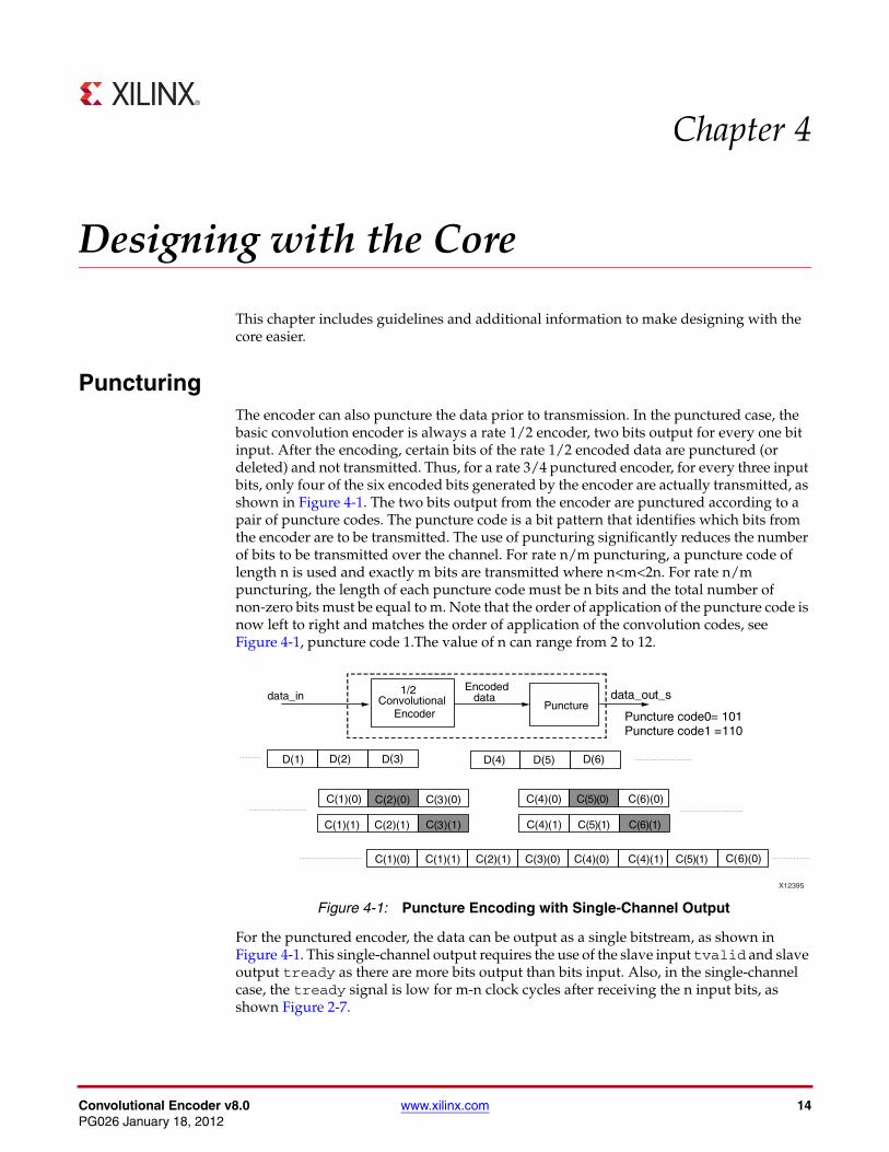
PuncturingThe encoder can also puncture the data prior to transmission. In the punctured case, the basic convolution encoder is always a rate 1/2 encoder, two bits output for every one bit input. After the encoding, certain bits of the rate 1/2 encoded data are punctured (or deleted) and not transmitted. Thus, for a rate 3/4 punctured encoder, for every three input bits, only four of the six encoded bits generated by the encoder are actually transmitted, as shown in Figure 4-1. The two bits output from the encoder are punctured according to a pair of puncture codes. The puncture code is a bit pattern that identifies which bits from the encoder are to be transmitted. The use of puncturing significantly reduces the number of bits to be transmitted over the channel. For rate n/m puncturing, a puncture code of length n is used and exactly m bits are transmitted where n<m<2n. For rate n/m puncturing, the length of each puncture code must be n bits and the total number of non-zero bits must be equal to m. Note that the order of application of the puncture code is now left to right and matches the order of application of the convolution codes, see Figure 4-1, puncture code 1.The value of n can range from 2 to 12.
For the punctured encoder, the data can be output as a single bitstream, as shown in Figure 4-1. This single-channel output requires the use of the slave input tvalid and slave output tready as there are more bits output than bits input. Also, in the single-channel case, the tready signal is low for m-n clock cycles after receiving the n input bits, as shown Figure 2-7.
X-Ref Target - Figure 4-1
Figure 4-1: Puncture Encoding with Single-Channel Output

Convolutional Encoder v8.0 www.xilinx.com 15PG026 January 18, 2012
Chapter 4: Designing with the Core
The data can also be output two bits at a time for the punctured encoder when the dual-channel output mode is selected, as shown in Figure 4-2. In this situation, there is less data output than input and the tready signal, if present, is only low if the master output data stream has been halted or the core reset. The master tvalid signal indicates when the output data is valid in both cases. For timing diagrams for the dual output case, see Figure 2-7.
AXI4-Stream ProtocolThe use of AXI4-Stream interfaces brings standardization and enhances interoperability of Xilinx® IP LogiCORE™ solutions. Other than general control signals such as aclk, aclken and aresetn, and event outputs, all inputs and outputs to the core are conveyed via AXI4-Stream channels. A channel consists of tvalid and tdata always, plus several optional ports and fields. In the Convolutional Encoder, the additional ports used are tready and tlast. Together, tvalid and tready perform a handshake to transfer a value, where the payload is tdata, and tlast. The payload is indeterminate when tvalid is deasserted.
The Convolutional Encoder operates on the values contained in the S_AXIS_DATA channel tdata fields and outputs the results in the tdata fields of the M_AXIS_DATA channel. The Convolutional Encoder core does not use input tlast as such, tlast is provided purely as a check that the core is in sync with the system and its use is optional. For further details on AXI4-Stream Interfaces see [Ref 1] and [Ref 2].
Basic HandshakeFigure 4-3 shows the transfer of data in an AXI4-Stream channel. tvalid is driven by the source (master) side of the channel and tready is driven by the receiver (slave). tvalid indicates that the value in the payload fields (tdata and tlast) is valid. tready indicates that the slave is ready to receive data. When both tvalid and tready are true in a cycle, a transfer occurs. The master and slave set tvalid and tready respectively for the next transfer appropriately.
X-Ref Target - Figure 4-2
Figure 4-2: Puncture Encoding with Dual-Channel Output
� �

Convolutional Encoder v8.0 www.xilinx.com 16PG026 January 18, 2012
Chapter 4: Designing with the Core
The full flow control of AXI4-Stream aids system design because the flow of data is self-regulating. Data loss is prevented by the presence of back pressure (tready), so that data is only propagated when the downstream datapath is ready to process it.
The core has one output channel: M_AXIS_DATA. If the output is prevented from off-loading data because m_axis_data_tready is low then data accumulates in the core. When the core’s internal buffers are full the core stops further operations. When the internal buffers fill, the tready (s_axis_data_tready) is deasserted to prevent further input. This is the normal action of back pressure.
X-Ref Target - Figure 4-3
Figure 4-3: Data Transfer in an AXI-Stream Channel
aclk
s_axis_data_tvalid
s_axis_data_tready
s_axis_data_tdata
s_axis_data_tlast
D0 D1 D2 D3 D4

Convolutional Encoder v8.0 www.xilinx.com 17PG026 January 18, 2012
Chapter 5
Detailed Example Design
Demonstration Test BenchWhen the core is generated using CORE Generator™, a demonstration test bench iscreated. This is a simple VHDL test bench that exercises the core.
The demonstration test bench source code is one VHDL file: <component_name>/demo_tb/tb_<component_name>.vhd in the CORE Generator output directory. Thesource code is comprehensively commented.
Using the Demonstration Test BenchThe demonstration test bench instantiates the generated Convolutional Encoder core.Either the behavioral model or the netlist can be simulated within the demonstration testbench.
• Behavioral model: Ensure that the CORE Generator project options are set to generate a behavioral model. After generation, this creates a behavioral model wrapper named <component_name>.vhd. Compile this file into the work library (see your simulator documentation for more information on how to do this).
• Netlist: If the CORE Generator project options were set to generate a structural model, a VHDL or Verilog netlist named <component_name>.vhd or <component_name>.v was generated. If this option was not set, generate a netlist using the netgen program, for example:
netgen -sim -ofmt vhdl <component_name>.ngc <component_name>_netlist.vhd
Compile the netlist into the work library (see your simulator documentation for moreinformation on how to do this). Then compile and simulate the demonstration test bench.View the test bench's signals in your simulator's waveform viewer to see the operations ofthe test bench.
The Demonstration Test Bench in DetailThe demonstration test bench performs the following tasks:
• Instantiates the core
• Generates a clock signal
• Drives the core's input signals to demonstrate core features
• Checks that the core's output signals obey AXI protocol rules (data values are not checked in order to keep the test bench simple)

Convolutional Encoder v8.0 www.xilinx.com 18PG026 January 18, 2012
Chapter 5: Detailed Example Design
• Provide signals showing the separate fields of AXI TDATA signals
The demonstration test bench drives the core input signals to demonstrate the features andmodes of operation of the core. The operations performed by the demonstration test benchare appropriate for the configuration of the generated core and are a subset of thefollowing operations:
1. An initial phase where the core is initialized and no operations are performed.
2. Drive random data into the core to demonstrate convolutional encoding.
3. Demonstrate the use of AXI handshaking signals tvalid and tready.
4. Demonstrate the effect of asserting aresetn.
5. If aclken is present: demonstrate the effect of toggling aclken.
Customizing the Demonstration Test BenchIt is possible to modify the demonstration test bench to use different source data. Sourcedata is generated randomly and driven into the core by the procedures of thes_data_stimuli process. The clock frequency of the core can be modified by changingthe CLOCK_PERIOD constant.
System Generator for DSP Graphical User InterfaceThe Convolutional Encoder core is available through Xilinx System Generator for DSP, adesign tool that enables the use of the model-based design environment Simulink® forFPGA design. The Convolutional Encoder core is one of the DSP building blocks providedin the Xilinx blockset for Simulink. The core can be found in the Xilinx Blockset in theCommunication section. The block is called “Convolutional Encoder 8.0." See the SystemGenerator User Manual for more information.
The controls in the System Generator GUI work identically to those in the CORE GeneratorGUI, although the layout has changed slightly. See CORE Generator GUI and Parameters,page 11.

Convolutional Encoder v8.0 www.xilinx.com 19PG026 January 18, 2012
Appendix 6
Migrating
This appendix describes migrating from older versions of the IP to the current IP release.
Parameter Changes in the XCO FileThe CORE Generator™ core update functionality can be used to update an existing XCO file from v7.0 to v8.0, but the update mechanism alone does not create a core compatible with v7.1. Table 6-1 shows the changes to XCO parameters from v7.0 to v8.0.
Table 6-1: XCO Parameter Changes from v7.0 to v8.0
Version 7.0 Version 8.0 Notes
component_name component_name Unchanged
constraint_length constraint_length Unchanged
convolution_code0 convolution_code0 Unchanged
convolution_code1 convolution_code1 Unchanged
convolution_code2 convolution_code2 Unchanged
convolution_code3 convolution_code3 Unchanged
convolution_code4 convolution_code4 Unchanged
convolution_code5 convolution_code5 Unchanged
convolution_code6 convolution_code6 Unchanged
convolution_code_radix Added in V8 for ease of use in entering convolutional codes.
dual_output dual_output Unchanged
input_rate input_rate Unchanged
output_rate output_rate Unchanged
puncture_code0 puncture_code0 Unchanged
puncture_code1 puncture_code1 Unchanged
tready Added in v8 for AXI control signal handshaking
ce aclken Renamed from ce to aclken for AXI standardization
fd_in Replaced with AXI control signals

Convolutional Encoder v8.0 www.xilinx.com 20PG026 January 18, 2012
Appendix 6: Migrating
Port Changes
nd Replaced with AXI control signals
rdy Replaced with AXI control signals
rfd Replaced with AXI control signals
rfdd Replaced with AXI control signals
synchronous_clear aresetn always present on core
Table 6-1: XCO Parameter Changes from v7.0 to v8.0 (Cont’d)
Version 7.0 Version 8.0 Notes
Table 6-2: Port Changes from v7.0 to v8.0
Version 7.0 Version 8.0 Notes
clk aclk Rename only
ce aclken Rename only
sclr aresetn Rename and change on sense (now active Low). Must now be asserted for at least 2 cycles
fd_in v8.0 does not require a pulse at the start of each block. s_axis_data_tvalid is used to detect this automatically.
nd s_axis_data_tvalid
rfd s_axis_data_tready
rffd Input data stream can be sampled when s_axis_data_tready is asserted
rdy m_axis_data_tvalid

Convolutional Encoder v8.0 www.xilinx.com 21PG026 January 18, 2012
Appendix 7
Additional Resources
Xilinx ResourcesFor support resources such as Answers, Documentation, Downloads, and Forums, see the Xilinx® Support website at:
http://www.xilinx.com/support.
For a glossary of technical terms used in Xilinx documentation, see:
http://www.xilinx.com/support/documentation/sw_manuals/glossary.pdf.
Solution CentersSee the Xilinx Solution Centers for support on devices, software tools, and intellectual property at all stages of the design cycle. Topics include design assistance, advisories, and troubleshooting tips.
References 1. Xilinx AXI Design Reference Guide (UG761)
2. AMBA 4 AXI4-Stream Protocol Version: 1.0 Specification
3. Synthesis and Simulation Design Guide (UG626)
4. Viterbi Decoder data sheet (PG027)
Technical SupportXilinx provides technical support at www.xilinx.com/support for this LogiCORE™ IP product when used as described in the product documentation. Xilinx cannot guarantee timing, functionality, or support of product if implemented in devices that are not defined in the documentation, if customized beyond that allowed in the product documentation, or if changes are made to any section of the design labeled DO NOT MODIFY.
See the IP Release Notes Guide (XTP025) for more information on this core. For each core, there is a master Answer Record that contains the Release Notes and Known Issues list for the core being used. The following information is listed for each version of the core:
• New Features
• Resolved Issues
• Known Issues

Convolutional Encoder v8.0 www.xilinx.com 22PG026 January 18, 2012
Appendix 7: Additional Resources
Ordering InformationContact your local Xilinx sales representative for pricing and availability on XilinxLogiCORE products and software.
Revision HistoryThe following table shows the revision history for this document.
Notice of DisclaimerThe information disclosed to you hereunder (the “Materials”) is provided solely for the selection and use of Xilinx products. To the maximum extent permitted by applicable law: (1) Materials are made available “AS IS” and with all faults, Xilinx hereby DISCLAIMS ALL WARRANTIES AND CONDITIONS, EXPRESS, IMPLIED, OR STATUTORY, INCLUDING BUT NOT LIMITED TO WARRANTIES OF MERCHANTABILITY, NON-INFRINGEMENT, OR FITNESS FOR ANY PARTICULAR PURPOSE; and (2) Xilinx shall not be liable (whether in contract or tort, including negligence, or under any other theory of liability) for any loss or damage of any kind or nature related to, arising under, or in connection with, the Materials (including your use of the Materials), including for any direct, indirect, special, incidental, or consequential loss or damage (including loss of data, profits, goodwill, or any type of loss or damage suffered as a result of any action brought by a third party) even if such damage or loss was reasonably foreseeable or Xilinx had been advised of the possibility of the same. Xilinx assumes no obligation to correct any errors contained in the Materials or to notify you of updates to the Materials or to product specifications. You may not reproduce, modify, distribute, or publicly display the Materials without prior written consent. Certain products are subject to the terms and conditions of the Limited Warranties which can be viewed at http://www.xilinx.com/warranty.htm; IP cores may be subject to warranty and support terms contained in a license issued to you by Xilinx. Xilinx products are not designed or intended to be fail-safe or for use in any application requiring fail-safe performance; you assume sole risk and liability for use of Xilinx products in Critical Applications: http://www.xilinx.com/warranty.htm#critapps.
© Copyright 2012 Xilinx, Inc. Xilinx, the Xilinx logo, Artix, ISE, Kintex, Spartan, Virtex, Zynq, and other designated brands included herein are trademarks of Xilinx in the United States and other countries. All other trademarks are the property of their respective owners.
Date Version Revision
1/18/12 1.0 Initial Xilinx release for AXI interfaces; previous non-AXI version of the data sheet is DS248.