Logic Engine User Manual - Computer Science · Logic Engine User Manual 4 1. ... The ED PLD Tool is...
93
Copyright ©2001 Indiana University Computer Science Department Logic Engine User Manual 1 Caleb Hess, Steven D. Johnson, Rob- ert W. Wehrmeister, Ingo Cyliax, Logic Engine User Manual Revised 2001
Transcript of Logic Engine User Manual - Computer Science · Logic Engine User Manual 4 1. ... The ED PLD Tool is...

Copyright ©2001 Indiana University Computer Science Department
Logic Engine User Manual 1
Caleb Hess, Steven D. Johnson, Rob-ert W. Wehrmeister, Ingo Cyliax,
Logic Engine User Manual
Revised 2001

Logic Engine User Manual 2
. . . . . . 8 . . . 9. . . .
. . .
. . . 14
. . . 19 . . . 20 . . . 21 . .
. . . 25
. . . 28 .
. . .
.
. . . 35
. . . 3. . . 40
1 Introduction . . . . . . . . . . . . . . . . . . . . . . . . . . . . . . . . . . . . . . . . . . . . . . . . . . . . . . . . . . . . . . . . 42 Installation . . . . . . . . . . . . . . . . . . . . . . . . . . . . . . . . . . . . . . . . . . . . . . . . . . . . . . . . . . . . . . . . . 6
2.1 Introduction. . . . . . . . . . . . . . . . . . . . . . . . . . . . . . . . . . . . . . . . . . . . . . . . . . . . . . . . . . . . . 62.2 Before Installation. . . . . . . . . . . . . . . . . . . . . . . . . . . . . . . . . . . . . . . . . . . . . . . . . . . .. . . . 62.3 Basic Installation. . . . . . . . . . . . . . . . . . . . . . . . . . . . . . . . . . . . . . . . . . . . . . . . . . . . . . . . . 72.4 Advanced Installation . . . . . . . . . . . . . . . . . . . . . . . . . . . . . . . . . . . . . . . . . . . . . . . . .. . 72.5 Starting Up the Logic Engine Software . . . . . . . . . . . . . . . . . . . . . . . . . . . . . . . . . . . 2.6 Installing Only the LE PI Library . . . . . . . . . . . . . . . . . . . . . . . . . . . . . . . . . . . . . . . . .2.7 Installing the LE Board. . . . . . . . . . . . . . . . . . . . . . . . . . . . . . . . . . . . . . . . . . . . . . . . . . 9
3 Using the Logic Engine Board . . . . . . . . . . . . . . . . . . . . . . . . . . . . . . . . . . . . . . . . . . . . . .123.1 Introduction. . . . . . . . . . . . . . . . . . . . . . . . . . . . . . . . . . . . . . . . . . . . . . . . . . . . . . . . . . . . 123.2 Tie Points . . . . . . . . . . . . . . . . . . . . . . . . . . . . . . . . . . . . . . . . . . . . . . . . . . . . . . . . . . . . . 123.3 Clock . . . . . . . . . . . . . . . . . . . . . . . . . . . . . . . . . . . . . . . . . . . . . . . . . . . . . . . . . . . . . . . . 123.4 Switches and Buttons . . . . . . . . . . . . . . . . . . . . . . . . . . . . . . . . . . . . . . . . . . . . . . . . . 123.5 LEDs . . . . . . . . . . . . . . . . . . . . . . . . . . . . . . . . . . . . . . . . . . . . . . . . . . . . . . . . . . . . . . . . . 143.7 Serial Port . . . . . . . . . . . . . . . . . . . . . . . . . . . . . . . . . . . . . . . . . . . . . . . . . . . . . . . . . . . . . 143.8 Placing Sockets in the Prototype Area . . . . . . . . . . . . . . . . . . . . . . . . . . . . . . . . . . . .
4 LE Panel . . . . . . . . . . . . . . . . . . . . . . . . . . . . . . . . . . . . . . . . . . . . . . . . . . . . . . . . . . . . . . . . . . 194.1 Introduction. . . . . . . . . . . . . . . . . . . . . . . . . . . . . . . . . . . . . . . . . . . . . . . . . . . . . . . . . . . . 194.2 How the LE Panel Tool Works. . . . . . . . . . . . . . . . . . . . . . . . . . . . . . . . . . . . . . . . . . 4.3 The LE Panel Tool upon Startup . . . . . . . . . . . . . . . . . . . . . . . . . . . . . . . . . . . . . . . .4.4 Status Field and Modes of Operation . . . . . . . . . . . . . . . . . . . . . . . . . . . . . . . . . . . . .4.5 Label and I/O Fields . . . . . . . . . . . . . . . . . . . . . . . . . . . . . . . . . . . . . . . . . . . . . . . . . .. . 224.6 Using Input Fields. . . . . . . . . . . . . . . . . . . . . . . . . . . . . . . . . . . . . . . . . . . . . . . . . . . . . . 244.7 Switch Fields. . . . . . . . . . . . . . . . . . . . . . . . . . . . . . . . . . . . . . . . . . . . . . . . . . . . . . . . . . . 244.8 File I/O . . . . . . . . . . . . . . . . . . . . . . . . . . . . . . . . . . . . . . . . . . . . . . . . . . . . . . . . . . . . . . . 254.9 Symbol Files . . . . . . . . . . . . . . . . . . . . . . . . . . . . . . . . . . . . . . . . . . . . . . . . . . . . . . . . . . . 254.10 Key Bindings and Menu Selections . . . . . . . . . . . . . . . . . . . . . . . . . . . . . . . . . . . . .
5 TERM . . . . . . . . . . . . . . . . . . . . . . . . . . . . . . . . . . . . . . . . . . . . . . . . . . . . . . . . . . . . . . . . . . . . 285.1 Introduction. . . . . . . . . . . . . . . . . . . . . . . . . . . . . . . . . . . . . . . . . . . . . . . . . . . . . . . . . . . . 285.2 Menus and Key Bindings . . . . . . . . . . . . . . . . . . . . . . . . . . . . . . . . . . . . . . . . . . . . . .
6 Common User Interface . . . . . . . . . . . . . . . . . . . . . . . . . . . . . . . . . . . . . . . . . . . . . . . . . . . . 306.1 Introduction. . . . . . . . . . . . . . . . . . . . . . . . . . . . . . . . . . . . . . . . . . . . . . . . . . . . . . . . . . . . 306.2 DESQview Interface . . . . . . . . . . . . . . . . . . . . . . . . . . . . . . . . . . . . . . . . . . . . . . . . . . 306.3 Menus . . . . . . . . . . . . . . . . . . . . . . . . . . . . . . . . . . . . . . . . . . . . . . . . . . . . . . . . . . . . . . . . 316.4 Dialog Boxes. . . . . . . . . . . . . . . . . . . . . . . . . . . . . . . . . . . . . . . . . . . . . . . . . . . . . . . . . . . 326.5 File I/O . . . . . . . . . . . . . . . . . . . . . . . . . . . . . . . . . . . . . . . . . . . . . . . . . . . . . . . . . . . . . . . 326.6 Tools Menu . . . . . . . . . . . . . . . . . . . . . . . . . . . . . . . . . . . . . . . . . . . . . . . . . . . . . . . . . . . . 346.7 Help System . . . . . . . . . . . . . . . . . . . . . . . . . . . . . . . . . . . . . . . . . . . . . . . . . . . . . . . . . . 356.8 Communication with the LE Board . . . . . . . . . . . . . . . . . . . . . . . . . . . . . . . . . . . . . .
4 ED PLD. . . . . . . . . . . . . . . . . . . . . . . . . . . . . . . . . . . . . . . . . . . . . . . . . . . . . . . . . . . . . . . . . . . 374.1 Introduction. . . . . . . . . . . . . . . . . . . . . . . . . . . . . . . . . . . . . . . . . . . . . . . . . . . . . . . . . . . . 374.2 Cypress PLD C 20G10 . . . . . . . . . . . . . . . . . . . . . . . . . . . . . . . . . . . . . . . . . . . . . . . .74.3 EDPLD Fuse Map Editor . . . . . . . . . . . . . . . . . . . . . . . . . . . . . . . . . . . . . . . . . . . . . .
Copyright ©2001 Indiana University Computer Science Department

Logic Engine User Manual 3
. . . 45. .
. . . . . . . . 57 . . . 61. 79
. . . . . . 80. . . 83 . . ..
4.4 File I/O . . . . . . . . . . . . . . . . . . . . . . . . . . . . . . . . . . . . . . . . . . . . . . . . . . . . . . . . . . . . . . . 414.5 EDPLD PLD Programmer . . . . . . . . . . . . . . . . . . . . . . . . . . . . . . . . . . . . . . . . . . . . . 4.6 Testing a 20G10 . . . . . . . . . . . . . . . . . . . . . . . . . . . . . . . . . . . . . . . . . . . . . . . . . . . . . . 454.7 Key Bindings . . . . . . . . . . . . . . . . . . . . . . . . . . . . . . . . . . . . . . . . . . . . . . . . . . . . . . .. . . 47
5 LE Assembler . . . . . . . . . . . . . . . . . . . . . . . . . . . . . . . . . . . . . . . . . . . . . . . . . . . . . . . . . . . . . . 505.1 Introduction. . . . . . . . . . . . . . . . . . . . . . . . . . . . . . . . . . . . . . . . . . . . . . . . . . . . . . . . . . . . 505.2 Editor. . . . . . . . . . . . . . . . . . . . . . . . . . . . . . . . . . . . . . . . . . . . . . . . . . . . . . . . . . . . . . . . . 505.3 LEASM Debugger . . . . . . . . . . . . . . . . . . . . . . . . . . . . . . . . . . . . . . . . . . . . . . . . . . . 535.4 A Design Example . . . . . . . . . . . . . . . . . . . . . . . . . . . . . . . . . . . . . . . . . . . . . . . . . . .. 545.5 Developing the Control Program . . . . . . . . . . . . . . . . . . . . . . . . . . . . . . . . . . . . . . . .5.6 The Micro Assembly Language . . . . . . . . . . . . . . . . . . . . . . . . . . . . . . . . . . . . . . . . .
I Logic Engine Programmer's Interface. . . . . . . . . . . . . . . . . . . . . . . . . . . . . . . . . . . . . . . . . A Introduction. . . . . . . . . . . . . . . . . . . . . . . . . . . . . . . . . . . . . . . . . . . . . . . . . . . . . . . . . . . . . 79B How the LEPI Works . . . . . . . . . . . . . . . . . . . . . . . . . . . . . . . . . . . . . . . . . . . . . . . . . . 79C Low Level Interface Routines. . . . . . . . . . . . . . . . . . . . . . . . . . . . . . . . . . . . . . . . . . . . D High Level Interface Routines . . . . . . . . . . . . . . . . . . . . . . . . . . . . . . . . . . . . . . . . . . . E Declaration File Syntax . . . . . . . . . . . . . . . . . . . . . . . . . . . . . . . . . . . . . . . . . . . . . . . . .. 84F Nomenclature. . . . . . . . . . . . . . . . . . . . . . . . . . . . . . . . . . . . . . . . . . . . . . . . . . . . . . . . . . . 87G Linking the Library . . . . . . . . . . . . . . . . . . . . . . . . . . . . . . . . . . . . . . . . . . . . . . . . . . . . . . 89
Copyright ©2001 Indiana University Computer Science Department

Logic Engine User Manual 4
g anof the
ford thistoolsrpose
Cins,e.ees
di--
ed
al I/
1. IntroductionThe Logic Engine consists of the Logic Engine Board and a set of software tools providininterface to the board. This manual describes the use of the software tools. A descriptionLogic Engine Board can be found in the Logic Engine Board Technical Reference Manual.
The Logic Engine Tool Set consists of four software tools, a library of routines which allowthe development of custom tools and an environment in which to run them. We have founset of tools to be extremely useful in our senior level digital design course. Some of thesewere designed with the course explicitly in mind, while others were designed as general putools. Below is a brief description of each tool:
All the tools, with the exception of the LE PI, were written to run in the DESQview1 environment.
LE Panel: The LE Panel tool is used to display information from the LE board on the Pscreen and to send information from the PC keyboard to the LE board. It is effect a virtual display which serves the same purpose as the lights, switcheand push buttons on the LE board, but which offers a more powerful interfacSignals wired to the lights, switches and push buttons of the LE board can bgrouped and displayed in a number of formats. Signals wired from the switchand push buttons can be controlled from the PC.
LE Asmb: The LE Asmb Tool is a microcode development system. It consists of a text etor, microcode assembler, downloader, and debugger, all in a unified environment. Features include:
- a source level debugger with single stepping and breakpoints.
- an emacs-like editor.
- viewing of object code.
- a rich micro-assembly language.
ED PLD: The ED PLD Tool is a PLD fuse map editor for use with the PLD burner on thLogic Engine Board. ED PLD also has the capability to read, burn, verify, antest PLDs. ED PLD supports only the PLD20G10 at this time.
LE Term: LE Term is a simple terminal emulator for use with designs that require seriO.
LE PI: The LE PI is a library of routines for use with the Microsoft Ca complier. Withthis library, users can develop specialized tools for use with their designs.
a.Microsoft C® is a trademark of Microsoft Corporation.
1. DESQview is a trademark of Quarterdeck Office Systems.
Copyright ©2001 Indiana University Computer Science Department

Logic Engine User Manual 5
fferslica-
They will not run unless DESQview is installed and running. The DESQview environment othree major features utilized by the Logic Engine tool set: the ability to switch between apptions, a standard way of dealing with windows and fields, and the ability to multitask.
Copyright ©2001 Indiana University Computer Science Department

Logic Engine User Manual 6
od, incedhavendedLogicESQ-talla-tallonly
ing
2. Installation
2.1. Introduction
There are two ways in which the Logic Engine software can be installed. The basic methwhich only the Logic Engine Tool set is available from within DESQview or the advanmethod, in which the Logic Engine Tool set is available along with other applications thatbeen set up for use with DESQview. If you are not currently using DESQview, it is recommethat the basic method be used. Later, when the full power of DESQview is desired, theEngine software can be reinstalled using the advanced method. If you are currently using Dview or wish to use all the power of DESQview immediately, use the advanced method of instion. If you wish to use only the LE PI tool to develop your own tools, you will not need to insDESQview or the Logic Engine software at all. See section 2.6 for the procedure to installthe LE PI tool.
2.2. Before Installation.
In order for the LE software tool set to run properly, your system should meet the followrequirements:
IBM Personal Computer or 100% compatibles
(386 class machine recommended)
640K Memory minimum
(1M to 4M recommended)
1 Floppy drive, 1 Hard drive with 1M available
Monochrome or Color monitor
(VGA Color monitor recommended)
Mouse
(Optional but highly recommended)
PC-DOS 2.0-3.3 or MS-DOS 2.0-3.3
DESQview version 2.01 or greater
All DESQview requirements
(see the DESQview manual)
Copyright ©2001 Indiana University Computer Science Department

Logic Engine User Manual 7
ion of
-
ter an.
hengine
pen
the.
view
DESQview must be installed before any of the software tools can be used (with the exceptthe LE PI tool.) To install DESQview, see the DESQview manual.
2.3. Basic Installation
Place the diskette labeledINSTALL in floppy driveA (other floppy drives can be used, simplyuse the appropriate drive letter instead ofA)TypeA: and press↵TypeTYPE README and press↵for any last minute instructions or modifications to the manualTypeINSTALL <dv> <le> and press↵,where:
- <dv> is the location where DESQview has been installed- <le> is the location where the LE software tools are to be installed- e.g.INSTALL C:\DV C:\LE ↵
If an error occurs during the installation, an appropriate error message will be displayed. Aferror, installation can be continued by correcting the problem and restarting the installation
During installation, messages will be displayed indicating the progress of the installation. Winstallation is complete, a message will be displayed indicating so. At this point the Logic Ensoftware is ready to run as described in section 2.5.
2.4. Advanced Installation
The advanced installation procedure will install the following programs into the DESQview OWindow menu with the key stokes listed below:
If any of these key strokes interfere with a program that is already installed in DESQview,advanced installation script (ADVANCE.BAT ) can be edited to make the appropriate changes
Performing the advanced installation procedure will create several new files in the DESQdirectory and modify the fileDESQVIEW.DVO . The old version of the fileDESQVIEW.DVOwill be stored in the fileDESQVIEW.OLD .
Program NameKey Stroke used to Open
Program
LE Panel PA
LE ASMB LE
ED PLD ED
TERM TR
Copyright ©2001 Indiana University Computer Science Department

Logic Engine User Manual 8
instal-gramtalled
plete,view
the
iews, onet it in
these but-
The advanced installation procedure is as follows:•Place the diskette labeledINSTALL in floppy driveA (other floppy drives can be used, simplyuse the appropriate drive letter instead ofA)•Follow the procedure for the basic installation (if this has not already been done)•TypeADVANCE <dv> <le> and press↵,where:
<dv> is the location where DESQview has been installed<le> is the location where the LE software tools have been installede.g.ADVANCE C:\DV C:\LE ↵
During the advanced installation, messages will be displayed indicating the progress of thelation. If there is a conflict between one of the programs being installed and another proalready installed, an error message will be displayed indicating that the program was not insand installation will proceed with the next program. Once the advanced installation is comthe programs will be available from the DESQview Open Window menu the next time DESQis started.
2.5. Starting Up the Logic Engine Software
After installing the Logic Engine Software, you should do the following:Add <le>/bin to thePATH environmental variable in autoexec.batAdd set LE=<le> to autoexec.bat,where:<le> is the location of the installed Logic Engine Soft-wareReboot
If the Logic Engine software was installed using only the basic method, you will be usingLogic Engine Menu to start up the Logic Engine tools. To start the Logic Engine Menu:TypeLE ↵This will start up DESQview and bring up a menu as illustrated in Fig. 1. DESQvshould not be running before the Logic Engine Menu is started. The menu has five selectionfor each of the Logic Engine tools and one for DOS. To start up one of these programs, selecone of three ways.
Type the two letters on the right side of the selection.eg. TypePA to select theLE Panel Tool.
Use the cursor keys to highlight the selection then press the Space Bar or Enter Key.Use the mouse to highlight the selection then press the left mouse button.
If the Logic Engine menu is ever obscured by other windows, it can be raised by movingmouse to a spot on the screen which is not occupied by a window and pressing the left mou
MENU˜˜˜˜˜˜˜¿‡ ‡‡LE Panel PA‡‡LE Asmb LE‡‡EDPld ED‡‡Term TR‡‡DOS DO‡˜˜˜˜˜˜˜˜˜˜˜
Copyright ©2001 Indiana University Computer Science Department

Logic Engine User Manual 9
ngineal for
thetwo
about
ust behe LEelow.)
itchesoving
ton.
If the Logic Engine software was installed using the advanced method, any of the Logic ETools can be started from the DESQview Open Window menu. See the DESQview manudetails about starting programs from the Open Window menu.
2.6. Installing Only the LE PI Library
If you desire to use only the LE PI library, it is possible to avoid installing DESQview andLogic Engine software. To be able to link your own programs to the LE PI library you needfiles off of theINSTALL diskette
\bin\lelib.lib
\include\lelib.h
These can be copied to a convenient location on your hard disk. See Chapter 8 for detailsusing these files.
2.7. Installing the LE Board
In order to operate the LE Board in a stand-alone fashion (no host PC), the power supply mconnected to the LE Board (see below) and plugged in and turned on. In order to operate tBoard with the host PC, the parallel connector must also be connected to the host (see bFig. 2 illustrates these connections.
There are three connectors located on the right side of the LE Board (board oriented with swface up and forward.) These connectors are, starting closest to the right most button and m
Copyright ©2001 Indiana University Computer Science Department

Logic Engine User Manual 10
away:
Parallel Connector:
This is a male DB25 (25 pin) connector. It is connected to the host PC'sparallel port (usually a female DB25 connector) via a male DB25/femaleDB25 parallel cable. This port is used for communication between thehost PC and the LE Board. If any of the LE software is used tocommunicate with the LE Board, this connection must be made.
Power Connector:
This is a 5 conductor, unisex, color coded connector. It is connected tothe power supply with an identical connector supplied with the powersupply. This connection provides +5V, ground, -12V, +12V and 'powergood' signals to the LE Board. The connection is made so that like col-ors of each connector match up. This connection must be made in orderto use the LE Board.
Serial Connector:
This is a female DB9 connector. It is connected to the host PC's serialport (usually a male DB25 connector, sometimes a male DB9 connector)via a female DB9/male DB25(DB9) serial cable. This undedicated portis used to provide a serial port between the LE Board and the host PC. Itis strictly for the designers use and is not used by any of the LE software.
Copyright ©2001 Indiana University Computer Science Department

Logic Engine User Manual 11
Copyright ©2001 Indiana University Computer Science Department

Logic Engine User Manual 12
s andswitchbits,
Figs.sed byand
ration.cornerman-e, yel-moder tiee fre-
ise, toy thehigh,
erated
ginethe
on the
3. Using the Logic Engine Board
3.1. Introduction
The Logic Engine Board has several features which aid in the testing and prototyping of chipsystems. The main features are: a general purpose prototyping area, a system clock, 32and button inputs, 128 LED's for display of outputs, a micro-sequencer with 40 commandand a serial port. The following sections describe how to use these features.
3.2. Tie Points
Fig. 1 illustrates the Logic Engine board with all the user tie points highlighted and labeled.2-4 are more detailed drawings of the board. The tie points are wire-wrap pins that can be usimply wiring from the user design in the prototype area to the tie point. Table 1 below, listsdescribes all the tie points on the board.
3.3. Clock
The clock supplied on the board is a variable rate clock with three selectable modes of opeEach mode can be selected using the three position toggle switch located in the lower leftof the board. The three positions are down: fast clock rate, up: slow clock rate, and middle:ual clock. The modes are also indicated by the lights above the switch: green: fast clock ratlow: slow clock rate and red: manual clock. The exact range of rates of the fast and slowcan be selected by wiring from tie points C1 (fast) and C2 (slow) to one of the clock divisopoints. This should already be set to some default configuration. In these two modes, thquency can be adjusted with the clock pot. To increase the frequency, turn the pot clockwdecrease, turn it counter clockwise. When the clock is in manual mode, it is controlled bpush button in the lower left corner of the board. When the button is depressed, the clock iswhen released, the clock is low.
There are six tie points (U0 - U5) on the board for access to the user clock. They are all genfrom the same signal run through separate buffers.
3.4. Switches and Buttons
There are 16 switch tie points (S0 - S15) and 16 button tie points (B0 - B15) on the Logic Enboard. All of the switches and 12 of the buttons can be controlled in manual mode fromswitches and buttons across the front of the board. The 16 switches on the board starting
Copyright ©2001 Indiana University Computer Science Department

Logic Engine User Manual 13
ht, areonedosi-on istion,
com-nts andftware
right, are connected to tie points S0 - S15. The 12 buttons on the board starting on the rigconnected to tie points B0 - B5 and B8 - B13. In manual mode, when a switch is posititoward the front of the board, the value on the correspoding tie point is low (0V). When ptioned away from the front of the board, the value is high (5V). In manual mode, when a buttin the up position, the value on the correspoding tie point is low (0V). When in the down posithe value is high (5V).
When in host mode, all 32 of the switch and button tie points can be controlled from the hostputer. In this case the switches and buttons on the board are disconnected from the tie poihave no effect on these signals. Refer to the proper chapter for information on how each sotool can control the switches and buttons.
Table 1: Tie Points
Function Tie Points InputOutput
Illustratedin Figure:
Description
Clock D0-D23 Output Fig. 2 Clock Divisor:
C1-C2 Input Fig. 2 Clock Selector:
U0-U5 Output Fig. 2 User Clock:
Switches S0-S15 Output Fig. 2 Switch Outputs:
Buttons B0-B15 Output Fig. 3 Button Outputs:
LED's L0-L127 Input Fig. 4 LED Inputs:
Micro-sequencer
P0-P39 Output Fig. 4 Pipeline Outputs:
PE.L Input Fig. 4 Pipeline Enable:
MAP0-MAP11
Input Fig. 4 Jump Map Inputs:
JMAP.L Output Fig. 4 Jump Map Enable:
CC.L Input Fig. 4 Condition Code:
Serial Port DTR Input Fig. 4
TD Input Fig. 4
RTS Input Fig. 4
RD Output Fig. 4
CD Output Fig. 4
DSR Output Fig. 4
CTS Output Fig. 4
Copyright ©2001 Indiana University Computer Science Department

Logic Engine User Manual 14
he sig-enceto theons.
ottomsolderin tod bot-
3.5. LEDs
There are 128 LED's that can be used to display signals. They are used by wire wrapping tnal to be displayed to one of the LED tie points (L0 - L128). The values of the LED's and hthe value of any signal wired to an LED can be read by software when in host mode. Referproper chapter for information on how each software tool can control the switches and butt
F. Microsequencer
3.7. Serial Port
3.8. Placing Sockets in the Prototype Area
The prototype area has a power grid on each side. The top side has a grid of 5V. And the bside has a grid of 0V. To place a socket in the prototype area, insert the socket, and make abridge from the Vcc pin to the grid on the top side and make a solder bridge from the GND pthe grid on the bottom side. Alternatively, you can use stake pins. Solder these to the top antom grids and wire wrap from these to the socket.
Copyright ©2001 Indiana University Computer Science Department

Logic Engine User Manual 15
Copyright ©2001 Indiana University Computer Science Department

Logic Engine User Manual 16
Copyright ©2001 Indiana University Computer Science Department

Logic Engine User Manual 17
Copyright ©2001 Indiana University Computer Science Department

Logic Engine User Manual 18
Copyright ©2001 Indiana University Computer Science Department

Logic Engine User Manual 19
Copyright ©2001 Indiana University Computer Science Department

Logic Engine User Manual 20
Copyright ©2001 Indiana University Computer Science Department

Logic Engine User Manual 21
Copyright ©2001 Indiana University Computer Science Department

Logic Engine User Manual 19
sendrvesffers aoardpush
e LEurrentdisplay
reacthis is
the
con-isplay.e dis-e speedrequestormant.f the
odenel.the
ld oflay theld, inrd, or
4. LE Panel
4.1. Introduction.
The LE Panel tool is used to display information from the LE board on the PC screen and toinformation from the PC keyboard to the LE board. It is in effect a virtual display which sethe same purpose as the lights, switches, and push buttons on the LE board, but which omore powerful interface. Signals wired to the lights, switches and push buttons of the LE bcan be grouped and displayed in a number of formats. Signals wired from the switches andbuttons can be controlled from the PC. This capability allows the user to interact with thboard entirely from the PC host. Displays can be constructed that are best suited to the cneeds of the design. And since the display is easily reconfigured, the user can change theas the need arises. Each configuration can be saved to disk to be retrieved at a later time.
4.2. How the LE Panel Tool Works
The LE Panel tool has two major tasks. The first is to take user input from the keyboard andto it. The second is to read information from the LE board and display it on the screen. Taccomplished by having one process for each task. Theuser input processtakes all input fromthe user, manages all the menus and windows and sends information to the LE board. Thepanelupdate processreads information from the LE board and displays it in the proper format inpanel window.
Thepanel update processcan operate in two modes: continuous update or user update. Intinuous update mode the panel update process is continuously running and updating the dThis gives the panel the feel of the light panel on the LE board since the signal values arplayed almost instantaneously. The rate at which the display can be updated depends on thand load of the host processor. In user update mode the user requests all updates. Eachcauses the panel update process to perform one update of the display and then become dAlthough this mode may not be very useful while debugging, it is handy to be able to turn ofpanel update process while doing other tasks on the computer.
The LE Panel tool can also control the operation of the clock on the LE board. When in run mthe clock is controlled from the LE board. Alternatively, the clock can be pulsed from the paThis will turn the clock off if it was in run mode and issue a single pulse of the clock. Whenclock is in run mode and running at a high rate, thepanel update processmay not be able to keepup with the changing signals and the values displayed may be invalid.
The main part of the LE panel display consists of 24 label field, I/O field pairs. The label fieeach pair is used to associate a name with a group of signals and the I/O field is used to dispgroup of signals in one of several formats. The I/O field can be configured to be an input fiewhich case it is used to display the value of a group of switches or buttons from the LE boa
Copyright ©2001 Indiana University Computer Science Department

Logic Engine User Manual 20
ard.ysicalof the
th behe PCmally,n takereg-
gisters
ped tone of
e LEAll ofthat is
ects ite LEto run
an output field, in which case it is used to display the value of a group of lights from the LE boInput fields can also be configured to accept input from the user, thus overriding the phswitches and buttons on the LE board. The user input is then sent to the LE board in placeswitches and buttons.
From the perspective of the host, the switches and buttons behave identically and will boreferred to as switches. Associated with each switch is a register which can be written by thost. The output of each switch is connected to the output of its corresponding register. Northe output of the register is disabled and the output of the switch is enabled. The PC host cacontrol of the switches by disabling the output of the switches and enabling the output of theisters. In addition to the 28 registers associated with the switches, there are 4 hidden rewhich are accessible from the PC host which do not have an associated switch or button.
In addition to the 24 label, I/O fields, the panel has 12 toggle input fields. Each can be mapone switch or button signal, creating a field that behaves like a toggle switch. Whenever othese fields is selected it toggles the value of the signal to which it is mapped.
All communication between the LE board and the PC host is done over the parallel port. Thboard contains numerous registers to store data or to control the behavior of the board.these registers can be written or read. The LE Panel tool assumes that it is the only processwriting to these registers, so when it puts the LE board in a certain mode of operation, it expto remain in that mode until otherwise instructed. If another process is also writing to thboard, the LE Panel tool can get confused about the state of the LE board. It is always bestonly one application that accesses the LE board at a time.
4.3. The LE Panel Tool upon Startu
Copyright ©2001 Indiana University Computer Science Department

Logic Engine User Manual 21
t cor-tle ofeverof the, LE
y therrenton-t auni-e LEfault.ctions
elds.
When the LE Panel tool is opened, a window similar to Fig. 1 should appear. In the upper lefner is the number assigned by DESQview to this window. To the right of the number is the tithe window. The LE Panel tool uses the window title to display the current file name. Whenthe current file name changes, for instance when a new configuration is loaded, the titlewindow will change. The configuration shown in Fig. 1 is simply an example. Upon startupPanel loads its initial configuration from the file "init.cfg".
Upon startup, the LE Panel tool first changes the current directory to the path indicated bHOME environmental variable. If the variable is not set or the path does not exist, the cudirectory will be the directory from which the LE Panel tool was started (initially set to "\le\cfig"). It then tries to load the file "init.cfg" from the current directory. If this file does not exisbell will sound. If after reading the mode of operation from "init.cfg" it is necessary to commcate with the LE board, it is first determined if the board is responding to requests. If so, thPanel is configured to that mode of operation. If not, the mode of operation is set to the deFor more information about configuration files and the various modes of operation, see se4.4 and 4.8.
The LE Panel window consists of five kinds of fields: Menu, Status, Label, I/O, and Switch fi
t.cfg˝˝˝˝˝˝˝˝˝˝˝˝˝˝˝˝˝˝˝˝˝˝˝˝˝˝˝˝˝˝˝˝˝˝˝˝˝˝˝˝˝˝˝˝˝˝˝˝˝˝˝˝˝˝˝˝˝˝˝˝l File(F1) Display(F2) Clock(F3) Tools(F4) HELP(F12) 11 Board Update
˜˜˜˜˜˜˜˜˜˜˜˜˜˜˜˜˜˜˜´˜˜˜˜˜˜˜˜˜˜˜˜˜˜˜˜˜˜˜˜˜˜˜˜˜´˜˜˜˜˜˜˜˜˜˜˜˜˜˜˜˜˜˜˜˜ 000 MA ‡ 0 LOAD-MA ‡ EXEC2 [000A] STA
˜˜˜˜˜˜˜˜˜˜˜˜˜˜˜˜˜˜˜¯˜˜˜˜˜˜˜˜˜˜˜˜˜˜˜˜˜˜˜˜˜˜˜˜˜¯˜˜˜˜˜˜˜˜˜˜˜˜˜˜˜˜˜˜˜˜ 0000 MEM ‡ 0 WRITE ‡ 100110 ALU
˜˜˜˜˜˜˜˜˜˜˜˜˜˜˜˜˜˜˜¯˜˜˜˜˜˜˜˜˜˜˜˜˜˜˜˜˜˜˜˜˜˜˜˜˜¯˜˜˜˜˜˜˜˜˜˜˜˜˜˜˜˜˜˜˜˜ 0000 MB ‡ 1 LOAD-MB ‡ 101 MUX
˜˜˜˜˜˜˜˜˜˜˜˜˜˜˜˜˜˜˜¯˜˜˜˜˜˜˜˜˜˜˜˜˜˜˜˜˜˜˜˜˜˜˜˜˜¯˜˜˜˜˜˜˜˜˜˜˜˜˜˜˜˜˜˜˜˜ 0000 PC ‡ 0 LOAD-PC ‡ 0 IE
˜˜˜˜˜˜˜˜˜˜˜˜˜˜˜˜˜˜˜¯˜˜˜˜˜˜˜˜˜˜˜˜˜˜˜˜˜˜˜˜˜˜˜˜˜¯˜˜˜˜˜˜˜˜˜˜˜˜˜˜˜˜˜˜˜˜ 0000 IR ‡ 1 LOAD-IR ‡ 0 HAL
˜˜˜˜˜˜˜˜˜˜˜˜˜˜˜˜˜˜˜¯˜˜˜˜˜˜˜˜˜˜˜˜˜˜˜˜˜˜˜˜˜˜˜˜˜¯˜˜˜˜˜˜˜˜˜˜˜˜˜˜˜˜˜˜˜˜ 0051 AC ‡ 00 ACS[0-1]‡ 0 CLO
˜˜˜˜˜˜˜˜˜˜˜˜˜˜˜˜˜˜˜¯˜˜˜˜˜˜˜˜˜˜˜˜˜˜˜˜˜˜˜˜˜˜˜˜˜¯˜˜˜˜˜˜˜˜˜˜˜˜˜˜˜˜˜˜˜˜ 0000 SW ‡ 0 LINK ‡
˜˜˜˜˜˜˜˜˜˜˜˜˜˜˜˜˜˜˜¯˜˜˜˜˜˜˜˜˜˜˜˜˜˜˜˜˜˜˜˜˜˜˜˜˜¯˜˜˜˜˜˜˜˜˜˜˜˜˜˜˜˜˜˜˜˜ 00 test ‡ ‡
˜˜˜˜˜˜˜˜˜˜˜˜˜˜˜˜˜˜˜`˜˜˜˜˜˜˜˜˜˜˜˜˜˜˜˜˜˜˜˜˜˜˜˜˜`˜˜˜˜˜˜˜˜˜˜˜˜˜˜˜˜˜˜˜˜ET CLEAR M-CLK CONT EXAM DEP MA-L MEM-L MB-L PC-L IR-L AC-˝˝˝˝˝˝˝˝˝˝˝˝˝˝˝˝˝˝˝˝˝˝˝˝˝˝˝˝˝˝˝˝˝˝˝˝˝˝˝˝˝˝˝˝˝˝˝˝˝˝˝˝˝˝˝˝˝˝˝˝˝˝˝˝˝ ‡
˜˜´˜˜˜˜˜˜ I/O Fields
Copyright ©2001 Indiana University Computer Science Department

Logic Engine User Manual 22
sts offrisk (*)tion.LE
the
on
eforeot, at from
t the
d canf up
cimal,
The purpose of each will be described in the following sections.
4.4. Status Field and Modes of Operation
The status field is located in the upper right of the LE Panel window. The status field consifour flags as illustrated in Fig. 2. TheFile Modified flag indicates whether the configuration othe panel has been modified since the last save or load. If the file has been modified an astewill be displayed for this flag. The remaining three flags indicate the current mode of operaThe Input Source flag indicates whether input to the LE board comes from the board or thePanel. If input comes from the LE Board,Board is displayed, otherwisePanel is displayed forthis flag. TheUpdate Statusflag indicates the status of the panel update process. Whenpanel update process is running,Update is displayed for this flag. TheClock Status flag indi-cates the status of the clock on the LE board. If the clock is running,Clock is displayed for thisflag.
There are five commands that change the mode of operation:Update Once, Update Continuous,Pulse Clock, Run Clock, andInput from Panel/Board . In addition, when a new configurationfile is loaded with theLoad File command, the mode of operation may change. For detailsthese commands see section 4.10.
To change the mode of operation, the LE Panel tool must communicate with the LE board. Bdoing this it first determines if the board is responding. If so, the command is executed. If nmessage to that effect is displayed and the mode of operation is changed to the default (inpuboard,panel update processstopped, clock stopped). To remove the displayed message, hiESC key.
4.5. Label and I/O Fields
The label and I/O fields are used to give a name and a view to a group of signals. An I/O fielbe configured to be an input or output field. An input field can be configured to display any oto 16 of the buttons or switches of the LE board. These can be displayed in either hexade
˝˝˝˝˝˝˝˝˝˝˝˝˝˝˝˝˝˝˝˝˝» LP(F12) 11/29/90” *Board Update Clock ” ˜˜˜˜˜˜˜˜˜˜˜˜˜˜˜˜˜˜˜˜˜” ‡ ‡ ‡ ‡ ‡ ‡ ‡ Clock Status ‡ ‡ Update Status ‡ Input Source File Modified
Copyright ©2001 Indiana University Computer Science Department

Logic Engine User Manual 23
ghtsmbol-are
. Thefieldf fiveincekeyfield.
gnals.not
lectedntly
sed tooctal,red
in thelds);mmasted bydingorder.uiva-
ed sig-ontainon the
gura-ition
most
decimal, octal, or binary. An output field can be configured to display any of up to 16 of the liof the LE board. These can be displayed in either hexadecimal, decimal, octal, binary, or syically. An I/O field that has been configured as an input field is highlighted while output fieldsnot.
When a label field is selected, a field definition dialog box as shown in Fig. 3 will be openeddialog box indicates the current configuration of this label, I/O field pair. From here the labeland its associated I/O field can be reconfigured. The field definition dialog box consists osections: the label, I/O, display, and signal definition sections along with the Done field. Sthis menu has a text input field, the TAB key is used to move between fields. Also, the ALTcan be used along with the capitalized letter of the select fields as a quick way to select aFor instance, ALT-H will select the Hex field even when the cursor is not over it.
The label definition field is used to assign a name of up to 8 characters to this group of siThis name will be displayed in the label field. The only limitation is that a comma (`,') canappear in the label.
The I/O definition section consists of 3 fields: off, input, and output. One of these can be seto configure the I/O field as either inactive, an input, or an output field. The field that is curreselected is highlighted.
The display definition section consists of 5 fields: hex, dec, oct, bin, and sym. These are uconfigure the contents of the I/O field to be displayed as either hexadecimal, decimal,binary, or symbolically. The field that is currently selected is highlighted. If the field is configuas an input field, the sym field configures the I/O field to be displayed as binary.
The signal definition section is used to define which signals are to be grouped and displayedI/O field. Signals are specified by their number (0-31 for input fields and 0-127 for output fiea group of signals is specified by a list of signal numbers or signal ranges separated by coand terminated with a semi-colon. A signal range is specified by two signal numbers separaa dash (`-'); it defines a list of signals beginning with the first signal number in the pair and enwith the second signal number of the pair. These can be in either increasing or decreasingFor instance, the signal groups: "12-5;", "12,11,10-7,6,5;", and "12,11,10,9,8,7,6,5;" are eqlent. Signal groups can consist of non-sequential signal numbers and can contain replicatnal numbers. For instance the signal group: "1,13,9,5-7,6,1;" is legal. Signal groups can cup to 16 signals. Chapter 9. describes how the lights, buttons, and switches are numberedLE board.
The Done field is used to accept the current configuration. If there are no errors in the confition the field definition menu is closed. If there are errors, a bell will sound and the field definmenu will remain open. At any time the ESC key can be used to abort the process.
A signal group is interpreted as a binary number with the most significant bit being the left
˝˝˝˝˝˝˝˝˝˝˝˝˝˝˝˝˝˝˝˝˝˝˝˝˝˝˝˝˝˝˝˝˝˝˝˝˝˝˝˝˝˝˝˝˝˝˝˝˝˝˝˝˝˝˝˝˝˝˝˝˝˝˝˝˝ Label: PC oFf Input Output Hex Dec oCt Bin Sym doNe Range: 37-48;
˝˝˝˝˝˝˝˝˝˝˝˝˝˝˝˝˝˝˝˝˝˝˝˝˝˝˝˝˝˝˝˝˝˝˝˝˝˝˝˝˝˝˝˝˝˝˝˝˝˝˝˝˝˝˝˝˝˝˝˝˝˝˝˝˝
Copyright ©2001 Indiana University Computer Science Department

Logic Engine User Manual 24
doneormatte is
eci-f theator, fol-e sig-cimal
er ises for
hen-ll will
ard isld in
ld willn bein theil an
se iserateeld-d asitioners tod toThe
signal in the group and the least significant bit being the rightmost. Whenever an update isthe value of all the signal groups are read from the LE board, converted to their appropriate fand displayed in the I/O field. The I/O field is not changed after reconfiguration until an updacompleted.
The value displayed in an I/O field is right justified in the field. In the case of hexadecimal, dmal, and octal formats, the letters `H', `D', and `O' are displayed in the leftmost position ofield respectively, to indicate the format of the display. In the case of binary format, no indicis displayed. In the case of a symbolic display, a symbol of up to 8 characters is displayedlowed by a four-digit hexadecimal number enclosed in brackets, representing the value of thnal group. If no symbol is mapped to the current value of the signal group, only the hexadevalue is displayed.
Upon closing a field definition menu configured as an output with symbolic display, the usprompted for the symbol map file name. Section 4.9 discusses how to create mapping filsymbolic display.
4.6. Using Input Fields
An I/O field that has been configured as an input field operates in two different modes. Winput is being taken from the LE board (board appears in the status field), the input field will display a value from the switches and buttons on the board. If the input field is selected a besound and nothing will happen. When input is being taken from the panel (panel appears in thestatus field), the switches and buttons are disabled and the switch register on the LE boenabled. The contents of this register is displayed in the input field. Selecting the input fiethis mode allows the user to modify the contents of the switch register. When selected, a fieappear directly below the input field with the current value being displayed. A new value caentered into this field and registered upon hitting the enter key. The new value is enteredformat that the field is configured to display. Note that the input field is not changed untupdate is completed.
4.7. Switch Fields
There are 12 switch fields located along the bottom of the LE Panel window. Each of theused to give a name to a single switch or button signal on the LE board. The Switch fields opin two modes. When input is being taken from the LE board, the switch fields operate in fidefinition mode. If a switch field is selected in this mode, a field definition menu is displayeillustrated in Fig. 4. This menu has three fields: the label definition field, the switch definfield, and the done field. The label definition field is used to give a name of up to 5 charactthis signal. The name will be displayed in the switch field. The switch definition field is usedefine the switch that this field will control. Switches are specified by their number (0-31).done field is used to accept the current field definition.
Copyright ©2001 Indiana University Computer Science Department

Logic Engine User Manual 25
ed, the. If aThe
y the
on iswithit wasis notinput
d File,nds. Ined; ifpted
ames.cheddis-t edi-he
al) fol-
lumnbined
When input is being taken from the panel, the switches and buttons on the board are disablswitch register on the LE board is enabled and the switch fields operate in toggle modeswitch field is selected in this mode, the value of the switch will be toggled on the LE board.current value of the switch does not get displayed in the switch field. If it is desired to displaswitch values, a label, I/O field can be used.
4.8. File I/O
Any configuration of the panel can be saved to a file for later retrieval. When a configuratisaved, the current configuration of all the label, I/O and switch fields is written to a file alongthe state of the status field. When a file is retrieved, the configuration is restored to the statein when saved. It may not be possible to restore the state of the status field if the LE boardresponding. In this case a message will be displayed and the mode of operation will be:source - board, panel update process - stopped, clock - stopped.
There are three commands that pertain to the saving and retrieval of configuration files: LoaSave File, and Save File As. See section 4.10. for details about these and other commaaddition, the Exit command will prompt the user whether to save a file that has been modifian output field has been reconfigured to display its value symbolically, the user will be promfor the name of the symbol file to be loaded.
4.9. Symbol Files
Symbol files are used to define a symbol map to map signal group values to symbolic nWhen an output field is configured to display its value symbolically, the symbol map is searfor the current value of the signal group. If found, the symbol corresponding to that value isplayed in the output field. Symbol files are simple text files that can be created using any textor. The first line of the file must contain the number (in decimal) of entries that follow. Tsubsequent lines contain one entry per line. Each entry consists of a value (in hexadecimlowed by its corresponding symbol of up to 8 characters.
4.10. Key Bindings and Menu Selections
Below is a table of all the commands and menu selections for the LE Panel tool. The first cois the key stroke for the command. The key strokes preceded by an `A-' refer to the key com
˝˝˝˝˝˝˝˝˝˝˝˝˝˝˝˝˝˝˝˝˝˝˝˝˝˝˝˝˝˝»” Label: CONT Switch: 4 Done”¨˝˝˝˝˝˝˝˝˝˝˝˝˝˝˝˝˝˝˝˝˝˝˝˝˝˝˝˝˝˝…
Copyright ©2001 Indiana University Computer Science Department

Logic Engine User Manual 26
TRLection.e LE
with the ALT key. The key strokes preceded by a `C-' refer to the key combined with the Ckey. The second column contains the title of the menu that contains this command as a selThe third column contains a description of the command. This table can be viewed within thPanel tool by selecting the help menu item or by hitting the F12 function key.
Copyright ©2001 Indiana University Computer Science Department

Logic Engine User Manual 27
hisenthe
tus
the
Ther-ca-
ed
ine to
ns.is-
ardsta-t
e of
Table 2:
KeyStroke
Menu Description
F1 - Activate File Menu.
F2 - Activate Display Menu.
F3 - Activate Clock Menu.
F4 - Activate Tools Menu.
F5 File Load File: The user is prompted for a configuration file to be loaded. Tfile will become the new current file. If the current configuration has bemodified since the last save, the user is prompted to save or abortchanges before loading the new file. The modification flag in the stafield is cleared after the new file is loaded.
F6 File Save File: The current configuration is saved into the current file andmodification flag in the status field is cleared.
A-F6 File Save File as: The current configuration is saved into a named file.user is prompted for a file name. If the file exists, it is overwritten, othewise it is created. The saved file becomes the current file. The modifition flag in the status field is cleared.
F7 File Clear Configuration: All fields of the current configuration are clearand the modification flag is set, the input source flag is set toboard, thepanel update process is stopped and the clock is stopped.
F8 Display Update Once: Request a single update from thepanel update process.This will cause the panel update process to be stopped if it is currentlycontinuous update mode. If the LE board is not responding, a messagthat effect will be displayed and no update will occur.
A-F8 Display Update Continuous: Put thepanel update processinto continuousupdate mode. If it is already in continuous update mode, nothing happeIf the LE board is not responding, a message to that effect will be dplayed and thepanel update process will be stopped.
C-F8 Display Input from Panel/Board: Toggle the source of input between the boand the panel. This also affects the behavior of the switch fields. Thetus field will reflect the current source of input. If the LE board is noresponding, a message to that effect will be displayed and the sourcinput will be set to board.
Copyright ©2001 Indiana University Computer Science Department

Logic Engine User Manual 28
thea
end-ut
. If
ce
F9 Clock Pulse Clock: Issue one pulse of the LE board clock. This will stopclock if it is currently in run mode. If the LE board is not responding,message to that effect will be displayed and no pulse will occur.
A-F9 Clock Run Clock: Put the LE board clock in run mode. The clock will run at thrate set by the controls on the LE board. If the LE board is not respoing, a message to that effect will be displayed and the clock will not be pin run mode.
F10 Tools LE Assembler: Start up an LE Assembler process in a new windowone is already running, make it the topmost window.
F11 Tools Terminal: Start up a terminal emulator process in a new window.
F12 - Help: Display this table in the help window.
ESC File Exit: Exit the LE Panel tool. If the configuration has been modified sinthe last save, the user is prompted to save or abort these changes.
Table 2:
Copyright ©2001 Indiana University Computer Science Department

Logic Engine User Manual 28
to theminal
of thecable
5. TERM
5.1. Introduction
The TERM tool was developed in order to have a simple terminal emulator that conformedCommon User Interface. It is intended to be used with Logic Engine designs that require terI/O. It does not however, have any direct connection with the Logic Engine.
Any other terminal emulator would work equally well if not better.
In order to use the TERM tool, a serial cable must be connected from the 9 pin serial portLogic Engine board to the serial port of the PC host. See Section 2.07 for details about thisand how to install it.
5.2. Menus and Key Bindings
Key
Stroke Menu Description
F1 - Activate File Menu.
F2 - Activate Baud Menu.
F3 - Activate Port Menu.
F4 - Activate Tools Menu.
F5 File Script File: Transmit named file.
F6 File Log File: Log all recieved characters to the named file.
ESC File Exit: Exit the TERM tool.
A-1 Baud 1200: Set the baud rate of the current port to 1200.
A-2 Baud 2400: Set the baud rate of the current port to 2400.
A-3 Baud 4800: Set the baud rate of the current port to 4800.
A-4 Baud 9600: Set the baud rate of the current port to 9600.
A-5 Baud 19200: Set the baud rate of the current port to 19200.
A-A Port Com 1: Set the current port to be COM1.
Copyright ©2001 Indiana University Computer Science Department

Logic Engine User Manual 29
A-B Port Com 2: Set the current port to be COM2.
F10 Tools LE Panel: Start up an LE Panel process in a new window.
A-F10 Tools LE Asmb: Start up an LE Asmb process in a new window.
F11 Tools EDPLD: Start up an EDPLD process in a new window.
A-F11 Tools TERM: Start up an EDPLD process in a new window.
C-F11 Tools DOS: Start up a DOS process in a new window.
F12 HELP Help: Display help information on the TERM tool.
Copyright ©2001 Indiana University Computer Science Department

Logic Engine User Manual 30
the
heitchulti-
sible, a, file I/
ssum-yed inly hitFig.
6. Common User Interface
6.1. Introduction
Several of the tools (LE Panel, LE ASMB, ED PLD, and TERM) were written to run in
DESQview1 environment. They will not run unless DESQview is installed and running. TDESQview environment offers three major features utilized by these tools: the ability to swbetween applications, a standard way of dealing with windows and fields, and the ability to mtask.
These tools also share a common philosophy towards the user interface. Wherever poscommon interface was used to accomplish similar tasks. This is most notable in the menusO, dialog boxes, and the DESQview interface.
6.2. DESQview Interface
After the tools have been installed, they can be started from the DESQview menu. This is aing the advanced installation procedure was used. The DESQview menu is usually displathe upper right hand corner of the screen but at times the menu will be hidden. If so, simpthe DESQview key (ALT-key) to redisplay the menu. The DESQview menu is illustrated in1.
1. DESQview is a trademark of Quarterdeck Office Systems.
DESQview Open Window O Switch Windows S Close Window C ˜˜˜˜˜˜˜˜˜˜˜˜˜˜˜˜˜˜˜˜˜˜ Rearrange R Zoom Z ˜˜˜˜˜˜˜˜˜˜˜˜˜˜˜˜˜˜˜˜˜˜ Mark M Transfer Scissors ˜˜˜˜˜˜˜˜˜˜˜˜˜˜˜˜˜˜˜˜˜˜ Help for DESQview ? Quit DESQview
Copyright ©2001 Indiana University Computer Science Department

Logic Engine User Manual 31
ee bar,
d hit-try is, a
mov-tails
oose,sed tolect the
t is toB keyis over.t cane keys.
LD,tools,pecial
fer-theti-the
associ-hen a
layedthe
To open a tool, first select theOpen Window item from the DESQview menu. This can be donby either moving the cursor over the item with the cursor keys or mouse and hitting the spacEnter key or left mouse button, or by simply typing the letterO. This will open up theOpen Win-dow menu. From here, a tool can be selected either by moving the cursor over the entry anting the space bar or the enter key or by typing the letters associated with the tool. If the ennot visible on this menu, thePage Downkey can be used to list more entries. Once selectedwindow will be opened for that tool.
DESQview also provides an interface for managing the windows. These functions include:ing, resizing, scrolling, closing and switching windows. See the DESQview manual for deabout these and other functions provided by the DESQview interface.
In various situations there will be a selection of fields presented from which the user must chor a field in which the user must enter text. In general, the cursor keys or the mouse can be umove between the fields and the space bar, Enter key or left mouse button can be used to sefield the cursor is over. The exception is in the case of a window that has a field in which texbe entered. In this case the TAB key moves the cursor to the next field and the Shifted TAmoves to the previous field. The space bar can be used to select the field that the cursorText is entered into fields by moving the cursor over the field and entering the text. The texbe edited using the left and right cursor keys, the end, home, insert, delete, and backspacAs a general rule the ESC key will cause the current activity to be aborted.
6.3. Menus
Each of the tools that conform to the Common User Interface (LE Panel, LE ASMB, ED Pand TERM) have a common menu interface. Across the top of the window of each of theseis a menu bar consisting of six fields. The first is the name of the application and has a sfunction described later. The next five are menu fields, the first labeledFile, the fourth and thefifth labeledTools andHELP respectively. The second and third menu fields are labeled difently for each tool. Each of the menu fields is associated with a function key shown parencally in each field. The date of the last modification of the tool is shown on the far right ofmenu bar.
The menus can be activated either by selecting them as described above or by pressing theated function key. For example, the Tools menu can be activated by pressing the F4 key. Wmenu is activated, a small pull-down menu containing a list of possible selections is dispbelow the menu title. The Display menu for the LE Panel tool is shown in Fig. 2. Displayed to
t.cfg˜˜˜˜˜˜˜˜˜˜˜˜˜˜˜˜˜˜˜˜˜˜˜˜˜˜˜˜˜˜˜˜˜˜˜˜˜˜˜˜˜˜˜˜˜˜˜˜˜˜˜˜˜˜˜˜˜˜˜˜˜F1) Display(F2) Clock(F3) Tools(F4) HELP(F12) Board Update Once: F8 O Update Continuous: A-F8 1 STATE Input From Panel/Board: C-F8 O 7777 WRITE 1 ALU 1
Copyright ©2001 Indiana University Computer Science Department

Logic Engine User Manual 32
efer toh theenu.menu
can berently used.
henright
This is
allfrom
hows a
right of each selection is an associated key stroke. The key strokes preceded by an `A-' rthe key combined with the ALT key. Those preceded by a `C-' refer to the key combined witCTRL key. This key stroke is used as a quick way to select an item without first selecting a mThey are not available when a menu is active. The actions that are performed when eachitem is selected are described in detail in the respective chapter for that tool. The ESC keyused to exit the menu without selecting an item. To activate another menu while one is curactive, the mouse, the left and right cursor keys, or the function keys for the menus can be
The first field of the menu bar which contains the name of the tool, is the icon field. Wselected, the window for the tool is reduced to the size of this field and positioned at the farof the screen. When selected again, the window is expanded to full size and repositioned.useful when you want to hide the window for a time without exiting the tool.
6.4. Dialog Boxes
At various times the user will be prompted for input with a dialog box. This is simply a smwindow that appears on top of the current window and has a selection of fields to chooseand/or a field in which to enter text. The fields can be selected as described above. Fig. 3 sfield definition dialog box from the LE Panel tool.
˝˝˝˝˝˝˝˝˝˝˝˝˝˝˝˝˝˝˝˝˝˝˝˝˝˝˝˝˝˝˝˝˝˝˝˝˝˝˝˝˝˝˝˝˝˝˝˝˝˝˝˝˝˝˝˝˝˝˝˝˝˝˝˝˝ Label: PC oFf Input Output Hex Dec oCt Bin Sym doNe Range: 37-48;
˝˝˝˝˝˝˝˝˝˝˝˝˝˝˝˝˝˝˝˝˝˝˝˝˝˝˝˝˝˝˝˝˝˝˝˝˝˝˝˝˝˝˝˝˝˝˝˝˝˝˝˝˝˝˝˝˝˝˝˝˝˝˝˝˝
Copyright ©2001 Indiana University Computer Science Department
Logic Engine User Manual 33
dialoga list,s: thelectr a filed intod theated
- then ofies orh list-the
.
newjuste ".."
ialog
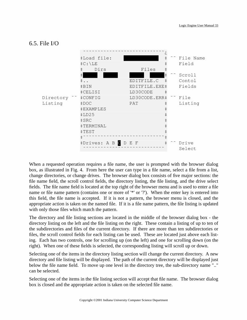
6.5. File I/O
When a requested operation requires a file name, the user is prompted with the browserbox, as illustrated in Fig. 4. From here the user can type in a file name, select a file fromchange directories, or change drives. The browser dialog box consists of five major sectionfile name field, the scroll control fields, the directory listing, the file listing, and the drive sefields. The file name field is located at the top right of the browser menu and is used to entename or file name pattern (contains one or more of '*' or '?'). When the enter key is enterethis field, the file name is accepted. If it is not a pattern, the browser menu is closed, anappropriate action is taken on the named file. If it is a file name pattern, the file listing is updwith only those files which match the pattern.
The directory and file listing sections are located in the middle of the browser dialog boxdirectory listing on the left and the file listing on the right. These contain a listing of up to tethe subdirectories and files of the current directory. If there are more than ten subdirectorfiles, the scroll control fields for each listing can be used. These are located just above eacing. Each has two controls, one for scrolling up (on the left) and one for scrolling down (onright). When one of these fields is selected, the corresponding listing will scroll up or down
Selecting one of the items in the directory listing section will change the current directory. Adirectory and file listing will be displayed. The path of the current directory will be displayedbelow the file name field. To move up one level in the directory tree, the sub-directory namcan be selected.
Selecting one of the items in the file listing section will accept that file name. The browser dbox is closed and the appropriate action is taken on the selected file name.
˜˜˜˜˜˜˜˜˜˜˜˜˜˜˜˜˜˜˜˜˜˜˜˜˜˜˜˜¿ ‡Load file: ‡ ˜˜ File Name ‡C:\LE ‡ Field ‡ Dirs Files ‡ ‡ ‡ ˜˜ Scroll ‡.. EDITFILE.C ‡ Contol ‡BIN EDITFILE.EXE‡ Fields ‡CELISI LD30CODE ‡ Directory ˜˜ ‡CONFIG LD30CODE.ERR‡ ˜˜ File Listing ‡DOC PAT ‡ Listing ‡EXAMPLES ‡ ‡LD25 ‡ ‡SRC ‡ ‡TERMINAL ‡ ‡TEST ‡ ‡˜˜˜˜˜˜˜˜˜˜˜˜˜˜˜˜˜˜˜˜˜˜˜˜˜˜˜˜‡ ‡Drives: A B C D E F ‡ ˜˜ Drive ˜˜˜˜˜˜˜˜˜˜˜˜˜˜˜˜˜˜˜˜˜˜˜˜˜˜˜˜ Select
Copyright ©2001 Indiana University Computer Science Department

Logic Engine User Manual 34
driverrent
nd thef thee I/O
move
LD,art upntical
The drive select fields are located at the bottom of the browser dialog box, labeled with theletters with the current drive highlighted. Selecting one of the drives will change the cudrive, update the directory and file listings, and update the path of the current directory.
The ESC key can be used to abort out of the browser with a null file name being accepted aappropriate action being performed for a null file (usually nothing). However, a change ocurrent directory or drive will take effect no matter how the browser is exited. Subsequent filwill be relative to the new current directory and drive.
There are several shortcuts available for the browser that allow the user to avoid having tothe cursor around a lot with the cursor keys or the mouse. They are listed below:
6.6. Tools Menu
Each of the tools that conform to the Common User Interface (LE Panel, LE ASMB, ED Pand TERM) have an identical tools menu. This menu consists of five selections used to stone of the tools or a DOS window. The key strokes associated with each selection are ide
Home Move the cursor to the File Name field
Page Up Scroll File Listing up
Page Down Scroll File Listing down
CTL-Page Up Scroll Directory Listing up
CTL-Page Down Scroll Directory Listing down
ALT-<n> Selects the <n>th item in the File Listing, where <n> isone of the numeric keys (1 representing the first item and0 representing the tenth item).
ALT-<c> Changes to the directory indicated by the letter <c>.Where <c> is one of the keys on the top row of the key-board starting with 'q' (representing the first item) andending with 'p' (representing the tenth item).
ALT-<c> Changes to the drive indicated by the letter <c>. Where<c> is one of the keys on the bottom row of the keyboardstarting with 'z' (representing drive A) and ending with'm' (representing drive G).
Copyright ©2001 Indiana University Computer Science Department

Logic Engine User Manual 35
LD,l tool.isplayh the
ialogialog
init.cfg˝˝˝˝˝˝˝˝˝˝˝˝˝˝˝˝˝˝˝˝»” LE Board is not responding ”¨˝˝˝˝˝˝˝˝˝˝˝˝˝˝˝˝˝˝˝˝˝˝˝˝˝˝˝˝…
within each tool. They are:
6.7. Help System
Each of the tools that conform to the Common User Interface (LE Panel, LE ASMB, ED Pand TERM) use a common help system. Fig. 5 shows the help dialog box for the LE PaneThe help dialog box consists of three fields across the top and a display area below. The darea contains a portion of the help information. The first two fields are used to scroll throughelp information and the third is used to close the help dialog box.
6.8. Communication with the LE Board
Most of the tools need to communicate with theLE Board at various times. In order to do this,the LE Board must be installed and turned on.Before any communication is attempted, thetool will first determine if the LE Board isactive, if so the communication will take place, if not the communication is aborted and a dbox as shown in Fig. 6, is displayed indicating that the LE Board is not responding. This d
F10 LE Panel
ALT-F10 LE ASMB
F11 ED PLD
ALT-F11 TERM
CTL-F11 DOS
P˝˝˝˝˝˝˝˝˝˝˝˝˝˝˝˝˝˝˝˝˝˝˝˝˝˝˝˝˝˝˝˝˝˝˝˝˝˝˝˝˝˝˝˝˝˝˝˝˝˝˝˝˝˝˝˝˝˝˝˝˝˝˝˝ CLOSE MENU DESCRIPTION ˜˜˜¯˜˜˜˜˜˜˜¯˜˜˜˜˜˜˜˜˜˜˜˜˜˜˜˜˜˜˜˜˜˜˜˜˜˜˜˜˜˜˜˜˜˜˜˜˜˜˜˜˜˜˜˜˜˜˜˜˜˜˜˜˜ ‡- ‡Activate File Menu. ˜˜˜¯˜˜˜˜˜˜˜¯˜˜˜˜˜˜˜˜˜˜˜˜˜˜˜˜˜˜˜˜˜˜˜˜˜˜˜˜˜˜˜˜˜˜˜˜˜˜˜˜˜˜˜˜˜˜˜˜˜˜˜˜˜ ‡- ‡Activate Display Menu. ˜˜˜¯˜˜˜˜˜˜˜¯˜˜˜˜˜˜˜˜˜˜˜˜˜˜˜˜˜˜˜˜˜˜˜˜˜˜˜˜˜˜˜˜˜˜˜˜˜˜˜˜˜˜˜˜˜˜˜˜˜˜˜˜˜ ‡- ‡Activate Clock Menu. ˜˜˜¯˜˜˜˜˜˜˜¯˜˜˜˜˜˜˜˜˜˜˜˜˜˜˜˜˜˜˜˜˜˜˜˜˜˜˜˜˜˜˜˜˜˜˜˜˜˜˜˜˜˜˜˜˜˜˜˜˜˜˜˜˜ ‡- ‡Activate Tools Menu. ˝˝˝˝˝˝˝˝˝˝˝˝˝˝˝˝˝˝˝˝˝˝˝˝˝˝˝˝˝˝˝˝˝˝˝˝˝˝˝˝˝˝˝˝˝˝˝˝˝˝˝˝˝˝˝˝˝˝˝˝˝˝˝˝˝
init.cfg˝˝˝˝˝˝˝˝˝˝˝˝˝˝˝˝˝˝˝˝»” LE Board is not responding ”¨˝˝˝˝˝˝˝˝˝˝˝˝˝˝˝˝˝˝˝˝˝˝˝˝˝˝˝˝…
Copyright ©2001 Indiana University Computer Science Department

Logic Engine User Manual 36
com-r dis-nicate
ing.tool toh thels are
ent itd EDwed tocase
ed it is
box can be closed by pressing the ESC key or the left mouse button. This will prevent mostmunication attempts when the board is not installed. However, if the board is turned off oconnected while the tool is running, the tool can get confused and may attempt to commuwith a non-functioning board. In this case it is possible for the tool to become hung.
Another problem that can arise while communcating with the LE Board is due to multitaskSince more than one tool can be running at the same time, it is possible for more than onebe commmunicating with the board. The system allows only one tool to communicate witboard at any one time. The problem can occur when the communications of several toointerweaved, such as:
1) tool A reads the state of the board
2) tool B changes the state of the board
3) tool A acts based on the state it read (which is now invalid)
The system does little to prevent this situation, so it is best to avoid it. It does attempt to previf tool A and tool B in the example above are the same tool. In the case of the LE ASMB anPLD tools, if subsequent instances of the tool are opened, the subseqent ones are not allocommunicate with the board. This is indicated by a bell when the window is opened. In theof the LE Panel tool, subseqent instances are not allowed. If a second instance is openimmediately closed and the first instance is raised to be the top window.
Copyright ©2001 Indiana University Computer Science Department

Logic Engine User Manual 37
testPLD
n bet termfuseutput
ctionalf thecon-
4. ED PLD
4.1. Introduction
The ED PLD Tool is a PLD fuse map editor with the capability to read, burn, verify, andPLDs using the PLD burner on the Logic Engine Board. ED PLD supports only the CypressC 20G10 at this time.
4.2. Cypress PLD C 20G10
The 20G10 is a 24 pin PLD with 12 input pins and 10 I/O pins. Each of the 10 output cells caconfigured as registered or combinational outputs, true high or true low outputs, and producor pin 13 output enable signals. The registered outputs are clocked by input pin 1. Thematrix consists of 44 signals (12 input, 10 output feedbacks, and their compliments). Each ocell has 9 product terms, 1 output enable term and 8 terms feeding an OR-gate. The funlogic diagram of the PLD C 20G10 is shown in Fig. 1 and the eight possible configurations ooutput cells are shown in Table 1 and Figs. 2-3. For more information on the PLD C 20G10,
Copyright ©2001 Indiana University Computer Science Department

Logic Engine User Manual 38
sult the data sheet.
Table 3:
Figure C2 C1 C0 Configuration
2A 0 0 0 Product Term OE Registered Active LOW
2B 0 0 1 Product Term OE Registered Active HIGH
3A 0 1 0 Product Term OE Combinational Active LOW
3B 0 1 1 Product Term OE Combinational Active HIGH
2C 1 0 0 Pin 13 OE Registered Active LOW
2D 1 0 1 Pin 13 OE Registered Active HIGH
3C 1 1 0 Pin 13 OE Combinational Active LOW
Copyright ©2001 Indiana University Computer Science Department

Logic Engine User Manual 39
Copyright ©2001 Indiana University Computer Science Department
Logic Engine User Manual 40
in thefiles
ed andn the
ndowf fourration
) anded indback
atrixcan be
inputbacks 1-3
on of
s willn each
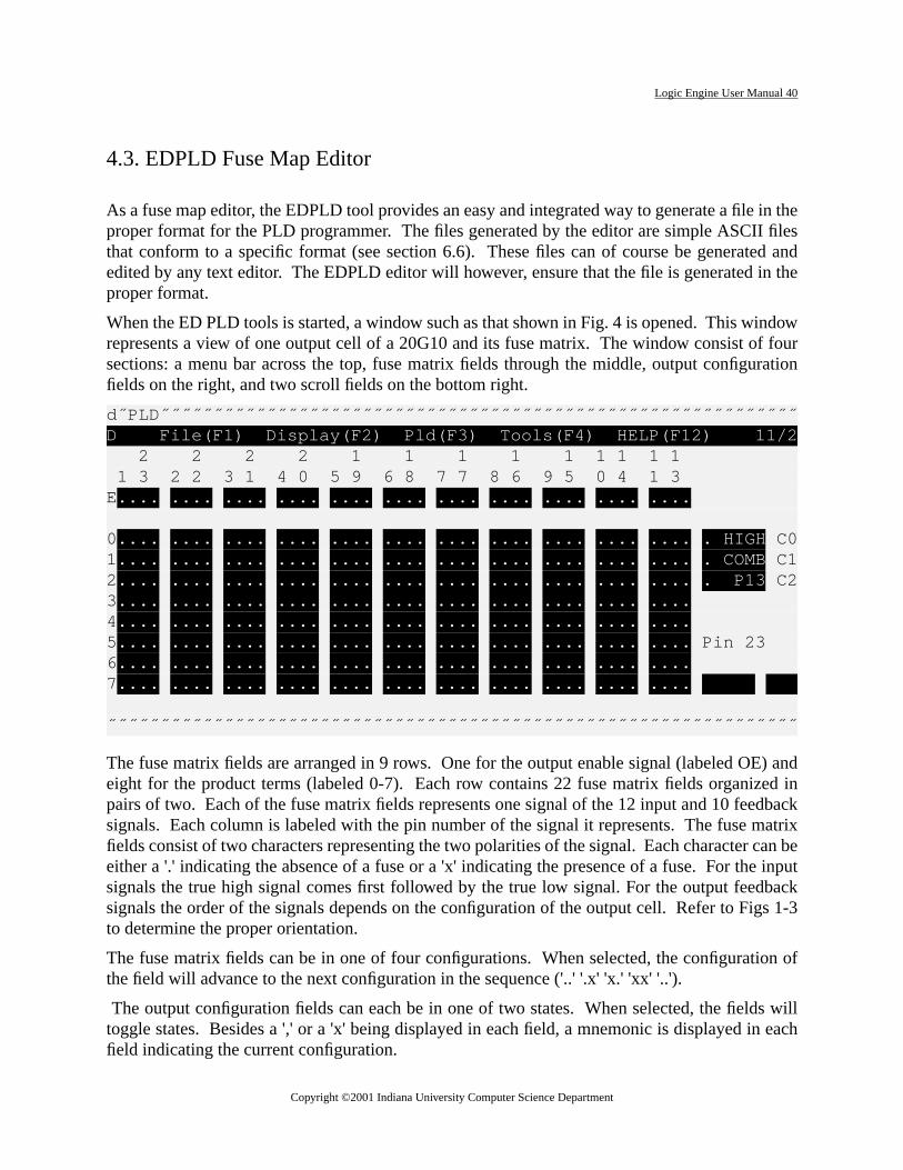
4.3. EDPLD Fuse Map Editor
As a fuse map editor, the EDPLD tool provides an easy and integrated way to generate a fileproper format for the PLD programmer. The files generated by the editor are simple ASCIIthat conform to a specific format (see section 6.6). These files can of course be generatedited by any text editor. The EDPLD editor will however, ensure that the file is generated iproper format.
When the ED PLD tools is started, a window such as that shown in Fig. 4 is opened. This wirepresents a view of one output cell of a 20G10 and its fuse matrix. The window consist osections: a menu bar across the top, fuse matrix fields through the middle, output configufields on the right, and two scroll fields on the bottom right.
The fuse matrix fields are arranged in 9 rows. One for the output enable signal (labeled OEeight for the product terms (labeled 0-7). Each row contains 22 fuse matrix fields organizpairs of two. Each of the fuse matrix fields represents one signal of the 12 input and 10 feesignals. Each column is labeled with the pin number of the signal it represents. The fuse mfields consist of two characters representing the two polarities of the signal. Each charactereither a '.' indicating the absence of a fuse or a 'x' indicating the presence of a fuse. For thesignals the true high signal comes first followed by the true low signal. For the output feedsignals the order of the signals depends on the configuration of the output cell. Refer to Figto determine the proper orientation.
The fuse matrix fields can be in one of four configurations. When selected, the configuratithe field will advance to the next configuration in the sequence ('..' '.x' 'x.' 'xx' '..').
The output configuration fields can each be in one of two states. When selected, the fieldtoggle states. Besides a ',' or a 'x' being displayed in each field, a mnemonic is displayed ifield indicating the current configuration.
d˝PLD˝˝˝˝˝˝˝˝˝˝˝˝˝˝˝˝˝˝˝˝˝˝˝˝˝˝˝˝˝˝˝˝˝˝˝˝˝˝˝˝˝˝˝˝˝˝˝˝˝˝˝˝˝˝˝˝˝˝˝˝D File(F1) Display(F2) Pld(F3) Tools(F4) HELP(F12) 11/2 2 2 2 2 1 1 1 1 1 1 1 1 1 1 3 2 2 3 1 4 0 5 9 6 8 7 7 8 6 9 5 0 4 1 3 E.... .... .... .... .... .... .... .... .... .... .... 0.... .... .... .... .... .... .... .... .... .... .... . HIGH C0 1.... .... .... .... .... .... .... .... .... .... .... . COMB C1 2.... .... .... .... .... .... .... .... .... .... .... . P13 C2 3.... .... .... .... .... .... .... .... .... .... .... 4.... .... .... .... .... .... .... .... .... .... .... 5.... .... .... .... .... .... .... .... .... .... .... Pin 23 6.... .... .... .... .... .... .... .... .... .... .... 7.... .... .... .... .... .... .... .... .... .... .... ˝˝˝˝˝˝˝˝˝˝˝˝˝˝˝˝˝˝˝˝˝˝˝˝˝˝˝˝˝˝˝˝˝˝˝˝˝˝˝˝˝˝˝˝˝˝˝˝˝˝˝˝˝˝˝˝˝˝˝˝˝˝˝˝˝
Copyright ©2001 Indiana University Computer Science Department

Logic Engine User Manual 41
num-
a file
singe ED
e filesap for-
s andis an
callyumber
Thef the
0-9).ourthf the
bits.es canextra
se bita fuse.
The two scroll fields are used to move the view to the next or previous output cell. The pinber of the current output cell is displayed above the scroll fields. ThePage UpandPage Downkeys can also be used for this function.
4.4. File I/O
The ED PLD software has several functions used to save and retrieve fuse maps.Save File-savesthe current fuse map into the current file. If there is no current file, the user is prompted forname. Save File As- saves the current fuse map into the named file andLoad File -loads thenamed file into the editor. Initially the current file is undefined. Each time a file is named, uany of these functions, that file becomes the current file and will be displayed as the title of thPLD window.
The files created by the ED PLD editor, called fuse map files, have a specific format. Thesare text files and can be edited using other text editors, but they must conform to the fuse mmat described below.
Each fuse map file consists of 10 configuration blocks which describe the product termarchitecture of each output cell. Fig. 5 is an example of one configuration block and Fig. 6example of a complete fuse map file.
Each configuration block consists of exactly 10 lines. The first line is a comment that typicontains the pin numbers corresponding to each column of the product terms and the pin nof the output cell. The second line contains the product term for the output enable signal.following 8 lines contain the product terms which feed the OR-gate of the output cell. Each oproduct term lines must contain in the first column, the number of the configuration block (The product term for the output enable signal must contain the letters 'OE' in the third and fcolumn. The remaining 8 product terms must contain in the fourth column, the number oproduct term (0-7).
Starting in column 5, each product term line contains a fuse pattern consisting of 44 fuseThese are typically arranged in 11 groups of 4 bits separated by a space, however, spacoccur throughout the line and are ignored. In addition, product terms 0, 1, and 2 contain anfuse bit beyond the 44 fuse bits which configure the architecture of the output cell. Each fuis either a `.' or a `x'. A `.' indicates the absence of a fuse and a `x' indicates the presence ofAny characters beyond the fuse bits are considered comments and are ignored.
1 23 2 22 3 21 4 20 5 19 6 18 7 17 8 16 9 15 1014 1113 PIN 23
0 OE x... .... .... .... .... .... .... .... .... .... ....
0 0 .... x... .... x... .x.. .x.. .x.. .x.. .xx. .x.. .x.x . H
0 1 .... x... .... x... .x.. .x.. .x.. .x.. .x.. .xx. .x.x . C
0 2 .... .x.. x... .... .... .... .... .... .... .... .... x P
0 3 .... .x.. x... .... .... .... .... .... .... .... ....
Copyright ©2001 Indiana University Computer Science Department

Logic Engine User Manual 42
t signalor thed byconfig-
ure thecribed
The product terms are arranged as a sequence of pairs of fuse bits, one pair for each inpuand output feedback signal. One fuse bit of each pair is for the true high and the other is ftrue low version of the signal. For the input signals the true high signal comes first followethe true low signal. For the output feedback signals the order of the signals depends on theuration of the output cell. Refer to Figs 1-3 to determine the proper orientation.
The three fuse bits beyond product terms 0, 1, and 2 (referred to as C0, C1, and C2) configarchitecture of the output cell. Each fuse bit controls one aspect of the configuration as desbelow:
C0 . : True High (H)
x : True Low (L)
C1 . : Combinational Output (C)
x : Registered Output (R)
C2 . : Output Enable source is pin 13 (C)
x : Output Enable source is product term (P)
Copyright ©2001 Indiana University Computer Science Department

Logic Engine User Manual 43
1 23 2 22 3 21 4 20 5 19 6 18 7 17 8 16 9 15 1014 1113 PIN 230 OE x... .... .... .... .... .... .... .... .... .... ....0 0 .... x... .... x... .x.. .x.. .x.. .x.. .xx. .x.. .x.x . H0 1 .... x... .... x... .x.. .x.. .x.. .x.. .x.. .xx. .x.x . C0 2 .... .x.. x... .... .... .... .... .... .... .... .... x P0 3 .... .x.. x... .... .... .... .... .... .... .... ....0 4 .... .x.. x... .... .... .... .... .... .... .... ....0 5 .... .x.. x... .... .... .... .... .... .... .... ....0 6 .... .x.. x... .... .... .... .... .... .... .... ....0 7 .... .x.. x... .... .... .... .... .... .... .... .... 1 23 2 22 3 21 4 20 5 19 6 18 7 17 8 16 9 15 1014 1113 PIN 221 OE x... .... .... .... .... .... .... .... .... .... ....1 0 .... x... .... x... .x.. .x.. .x.. .x.. .xx. .x.. .x.x . H1 1 .... x... .... x... .x.. .x.. .x.. .x.. .x.. .xx. .x.x . C1 2 .... .x.. x... .... .... .... .... .... .... .... .... x P1 3 .... .x.. x... .... .... .... .... .... .... .... ....1 4 .... .x.. x... .... .... .... .... .... .... .... ....1 5 .... .x.. x... .... .... .... .... .... .... .... ....1 6 .... .x.. x... .... .... .... .... .... .... .... ....1 7 .... .x.. x... .... .... .... .... .... .... .... .... 1 23 2 22 3 21 4 20 5 19 6 18 7 17 8 16 9 15 1014 1113 PIN 212 OE x... .... .... .... .... .... .... .... .... .... ....2 0 .... x... .... x... .x.. .x.. .x.. .x.. .x.. .x.. .xx. . H2 1 .... .x.. .x.. .... .... .... .... .... .... .... .... . C2 2 .... .x.. .x.. .... .... .... .... .... .... .... .... x P2 3 .... .x.. .x.. .... .... .... .... .... .... .... ....2 4 .... .x.. .x.. .... .... .... .... .... .... .... ....2 5 .... .x.. .x.. .... .... .... .... .... .... .... ....2 6 .... .x.. .x.. .... .... .... .... .... .... .... ....2 7 .... .x.. .x.. .... .... .... .... .... .... .... .... 1 23 2 22 3 21 4 20 5 19 6 18 7 17 8 16 9 15 1014 1113 PIN 203 OE x... .... .... .... .... .... .... .... .... .... ....3 0 .... x... .... x... .x.. .x.. .... .x.. ..x. .... ...x . H3 1 .... x... .... x... .x.. .x.. .... .x.. .... ..x. ...x . C3 2 .... x... .... x... .x.. .x.. .... .x.. .... .... x... x P3 3 .... x... .... x... .x.. .x.. .... .x.. .... x... ....3 4 .... x... .... x... .x.. .x.. .... .x.. x... .... ....3 5 .... x... .... x... .x.. .x.. x... .... .... .... ....3 6 .... x... .... x... .x.. .x.. x... .... .... .... ....3 7 .... x... .... x... .x.. .x.. x... .... .... .... .... 1 23 2 22 3 21 4 20 5 19 6 18 7 17 8 16 9 15 1014 1113 PIN 194 OE x... .... .... .... .... .... .... .... .... .... ....4 0 .... .... .... x... .x.. .... .x.. .... .xx. ...x ...x . H4 1 .... .... .... x... .x.. .... .x.. .... .x.. .... x... . C4 2 .... .... .... x... .x.. .... .x.. .... .x.. x... .... x P4 3 .... .... .... x... .x.. .... .x.. x... .... .... ....4 4 .... .... .... x... .x.. x... .... .... .... .... ....4 5 .... .x.. .... .... .... .... .... .... .... .... ....4 6 .... .x.. .... .... .... .... .... .... .... .... ....4 7 .... .x.. .... .... .... .... .... .... .... .... .... 1 23 2 22 3 21 4 20 5 19 6 18 7 17 8 16 9 15 1014 1113 PIN 185 OE x... .... .... .... .... .... .... .... .... .... ....5 0 .... x... .... x... .... .x.. .x.. .... .... .x.. x... . H5 1 .... x... .... x... .... .x.. .x.. .... x... .... .... . C5 2 .... x... .... x... .... .x.. .x.. x... .... .... .... x P5 3 .... x... .... x... x... .... .... .... .... .... ....5 4 .... x... .... x... x... .... .... .... .... .... ....5 5 .... x... .... x... x... .... .... .... .... .... ....5 6 .... x... .... x... x... .... .... .... .... .... ....5 7 .... x... .... x... x... .... .... .... .... .... .... 1 23 2 22 3 21 4 20 5 19 6 18 7 17 8 16 9 15 1014 1113 PIN 176 OE .... .... .... .... .... .... .... .... .... .... ....6 0 ..xx .... .... .... .... .... .... .... .... .... .... . H6 1 ..xx .... .... .... .... .... .... .... .... .... .... . C6 2 ..xx .... .... .... .... .... .... .... .... .... .... x P6 3 ..xx .... .... .... .... .... .... .... .... .... ....6 4 ..xx .... .... .... .... .... .... .... .... .... ....6 5 ..xx .... .... .... .... .... .... .... .... .... ....6 6 ..xx .... .... .... .... .... .... .... .... .... ....6 7 ..xx .... .... .... .... .... .... .... .... .... .... 1 23 2 22 3 21 4 20 5 19 6 18 7 17 8 16 9 15 1014 1113 PIN 167 OE .... .... .... .... .... .... .... .... .... .... ....7 0 .... .... .... .... .x.. .x.. .x.. .x.. .x.x .x.x .x.x x L7 1 .... .... .... .... .x.. .x.. .x.. .x.. .x.x .x.x .x.x . C7 2 .... .... .... .... .x.. .x.. .x.. .x.. .x.x .x.x .x.x x P7 3 .... .... .... .... .x.. .x.. .x.. .x.. .x.x .x.x .x.x7 4 .... .... .... .... .x.. .x.. .x.. .x.. .x.x .x.x .x.x7 5 .... .... .... .... .x.. .x.. .x.. .x.. .x.x .x.x .x.x7 6 .... .... .... .... .x.. .x.. .x.. .x.. .x.x .x.x .x.x7 7 .... .... .... .... .x.. .x.. .x.. .x.. .x.x .x.x .x.x 1 23 2 22 3 21 4 20 5 19 6 18 7 17 8 16 9 15 1014 1113 PIN 158 OE ..xx xxxx xxxx xxxx xxxx xxxx xxxx xxxx xxxx xxxx xxxx8 0 .... .... .... .... .... .... .... .... .... .... .... . H8 1 .... .... .... .... .... .... .... .... .... .... .... . C8 2 .... .... .... .... .... .... .... .... .... .... .... x P8 3 .... .... .... .... .... .... .... .... .... .... ....8 4 .... .... .... .... .... .... .... .... .... .... ....8 5 .... .... .... .... .... .... .... .... .... .... ....8 6 .... .... .... .... .... .... .... .... .... .... ....8 7 .... .... .... .... .... .... .... .... .... .... .... 1 23 2 22 3 21 4 20 5 19 6 18 7 17 8 16 9 15 1014 1113 PIN 149 OE ..xx xxxx xxxx xxxx xxxx xxxx xxxx xxxx xxxx xxxx xxxx
Copyright ©2001 Indiana University Computer Science Department

Logic Engine User Manual 44
ng the
. Tole-file,
rify-avail-wille zero
f leds.as theing ort therted or10 isalogmes-
ockettle isto thevice.This
s ofl bethe
r of
Alltain-
Beyond each of these three fuse bits there is typically a single character comment indicaticonfiguration of the output cell. These characters are given above in parenthesis.
Although the fuse map file format is rigid, creating and editing a fuse map file is quite easycreate a new file, simply enter thepld program and select option 2 (Save buffer) and specify a finame. This will save the initial empty buffer into the named file. To edit an existing fuse mapuse your favorite text editor in overstrike mode to alter the fuse bits.
4.5. EDPLD PLD Programmer
There are several functions available in the ED PLD editor for testing, programming, and veing a 20G10 in the programmer socket on the Logic Engine Board. These functions are allable under thePld menu and are described below in section 6.7. Each of these functionsprompt the user to insert a 20G10 into the programmer socket. The programmer socket is thinsertion force socket located near the center of the Logic Engine board below the bank oThe 20G10 should be oriented in the socket so that pin 1 is on the left (the same orientationother chips on the board.) The lever on the socket should be in the up position when insertremoving a chip and in the down position to lock a chip into the socket. It is important tha20G10 not be inserted until the prompt appears and at not time should a 20G10 be inseremoved when one of the leds surrounding the programmer socket is on. After the 20Ginserted, hit any key to proceed with the operation. Some of the functions will display diboxes indicating the sucess or failure of the operation. Hit any key to remove one of thesesages. TheTest Device function is a little more involved and is described in the next section.
4.6. Testing a 20G10
The EDPLD tool has the ability to apply a set of test vectors to a 20G10 in the programmer sand read the outputs of the 20G10. When theTest Devicefunction is selected, the user will firsbe prompted to supply the file name of a test vector file. The format of a test vector fidescribed below. After supplying the file name, the user is prompted to insert the 20G10 inprogramming socket. After the 20G10 is inserted, hit any key to begin the testing of the deAfter the device has been tested, a window will be displayed showing the results of the test.window can be scrolled using the cursor keys. The window can only display up to fifty lineinformation. If the information is longer than fifty lines, it will be truncated and a message wildisplayed at the bottom of the window so indicating. This window can be closed by hittingESC key. After the window is closed, a dialog box will be displayed indicating the numbeerrors that occured during testing.
The output of the testing can also be logged to a file. This can be done by use of theLog Filefunction under the file menu. This function will prompt the user for the name of the log file.subsequent output from testing will be sent to this file and no window will be displayed coning this information. Also, the information being sent to the log file will not be truncated.
Copyright ©2001 Indiana University Computer Science Department
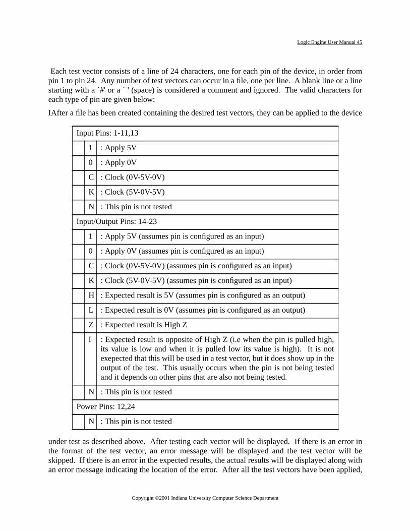
Logic Engine User Manual 45
r fromliners for
device
rror inill beg withplied,
Each test vector consists of a line of 24 characters, one for each pin of the device, in ordepin 1 to pin 24. Any number of test vectors can occur in a file, one per line. A blank line or astarting with a `#' or a ` ' (space) is considered a comment and ignored. The valid characteeach type of pin are given below:
IAfter a file has been created containing the desired test vectors, they can be applied to the
under test as described above. After testing each vector will be displayed. If there is an ethe format of the test vector, an error message will be displayed and the test vector wskipped. If there is an error in the expected results, the actual results will be displayed alonan error message indicating the location of the error. After all the test vectors have been ap
Input Pins: 1-11,13
1 : Apply 5V
0 : Apply 0V
C : Clock (0V-5V-0V)
K : Clock (5V-0V-5V)
N : This pin is not tested
Input/Output Pins: 14-23
1 : Apply 5V (assumes pin is configured as an input)
0 : Apply 0V (assumes pin is configured as an input)
C : Clock (0V-5V-0V) (assumes pin is configured as an input)
K : Clock (5V-0V-5V) (assumes pin is configured as an input)
H : Expected result is 5V (assumes pin is configured as an output)
L : Expected result is 0V (assumes pin is configured as an output)
Z : Expected result is High Z
I : Expected result is opposite of High Z (i.e when the pin is pulled high,its value is low and when it is pulled low its value is high). It is notexepected that this will be used in a test vector, but it does show up in theoutput of the test. This usually occurs when the pin is not being testedand it depends on other pins that are also not being tested.
N : This pin is not tested
Power Pins: 12,24
N : This pin is not tested
Copyright ©2001 Indiana University Computer Science Department

Logic Engine User Manual 46
is antors:
a message will be displayed indicating the total number of errors which occurred. Belowexample set of test vectors followed by an example output from running the set of test vecTest Vectors:
10000010000N0NNNNNNNNNHN10000001000N0NNNNNNNNNHN10000000100N0NNNNNNNNNHN10000000000N0NNNNpNNNNLN01111111111N1NNNNHHNNNZN
Output:VECTOR: 10000010000N0NNNNNNNNNHN : PassedVECTOR: 10000001000N0NNNNNNNNNHN : PassedVECTOR: 10000000100N0NNNNNNNNNHN : PassedERROR: Illegal character in vector: pVECTOR: 10000000000N0NNNNpNNNNLN : Skipped
VECTOR: 01111111111N1NNNNHHNNNZN : FailedRESULTS: 01111111111N1ZZZZZLLLZZNERRORS: ^^Test Completed with 3 Errors
4.7. Key Bindings
Copyright ©2001 Indiana University Computer Science Department

Logic Engine User Manual 47
ted
no
st
e).
ser
ketheis
merthe
erdif-sert
Table 4:
Key
Stroke Menu Description
F1 - Activate File menu.
F2 - Activate Display menu.
F3 - Activate Pld menu.
F4 - Activate Tools menu.
F12 - Activate Help menu.
F5 File Load File: Load a fuse map file into the buffer. The user is prompfor the file name. This file becomes the current file.
F6 File Save File: Save the current buffer into the current file. If there iscurrent file the user is prompted for the file name.
A-F6 File Save File As: Save the current buffer into the named file.
F7 File Log File: Name the file for logging output from the application of tevectors.
ESC File Exit:
Page Down Display Next Block: Move view to the next output cell.
Page Up Display Previous Block: Move view to the previous output cell.
DEL Display Clear Block: Set all fuses for this output cell to '.' (absence of a fus
A-B Pld Blank Test: Test for a blank device in the PLD Burner socket. The uis prompted to insert the device in the socket at the proper time.
A-P Pld Program Device: Program the device in the PLD Programmer socwith the contents of the buffer. The user is prompted to insert tdevice at the proper time. If the device is not blank, the userprompted whether to continue.
A-R Pld Read Device: Read the contents of the device in the PLD Programsocket into the buffer. The user is prompted to insert the device insocket at the proper time.
A-V Pld Verify Device: Read the contents of the device in the PLD Programmsocket and compare it to the contents of the buffer. The number offerences between the two is displayed. The user is prompted to inthe device in the socket at the proper time.
Copyright ©2001 Indiana University Computer Science Department

Logic Engine User Manual 48
ro-the
A-T Pld Test Device: Apply a set of test vectors to the device in the PLD Pgrammer socket. The user is prompted to insert the device insocket and for the name of the file containing the test vectors.
Table 4:
Copyright ©2001 Indiana University Computer Science Department

Logic Engine User Manual 49
Copyright ©2001 Indiana University Computer Science Department

Logic Engine User Manual 50
bler,
ullto beTable 1
pro-icroas-
, it canfromring
ssagersoron. If
cursored.down-
re are
uccess-objecth dis-
5. LE Assembler
5.1. Introduction
LEASM is a microcode developmenttool which consists of a text editor, microcode assemdownloader, and debugger, all in a unified environment. Features include:
• a source level debugger with single stepping and breakpoints.
• an emacs-like editor.
• viewing of object code.
• a rich micro-assembly language.
5.2. Editor
Built into the LEASM Tool is a simple text editor with emacs-like key bindings. It is not a ffeatured editor and as such is not intended to be used for large editing task. It is intendedused as a quick and easy way to make changes to source code during debugging sessions.lists the key bindings available in the editor
There are several functions built into the editor which allow for the assembly of microcodegrams. These are listed in Table 2. Section 5.6 describes the syntax and sematics of the msembly language.
Once a microassembly program has been loaded into the editor or created within the editorbe assembled using the Assemble/Load function. This will assemble the program startingthe top of the file, no matter where the cursor is currently located. If any errors occur duassembly, the cursor will be moved to the beginning of the offending line and an error mewill be displayed in the status region (see below). The Next-Error function will move the cuto the beginning of the line of the next error and display an error message in the status regino more errors exist, the cursor will be moved to the top of the file.
If there are no errors, the assembled code is downloaded to the Logic Engine Board and thewill be moved to the starting line of the microcode (location 0). This line will also be highlightIf the board is not present, a message will be displayed indicating that the code was notloaded and the cursor will be moved to the top of the file.
The status region is used to display various information about the status of the file. Thethree contexts in which different information is displayed. As mentioned above,
cursor is on has an assembly error, an error message is displayed. If the code has been sfully assembled and the cursor is on a line which contains a program statement, then thecode for that line is displayed. In all other cases, the status region contains three fields whic
Copyright ©2001 Indiana University Computer Science Department

Logic Engine User Manual 51
g indi-itor. Ifthisce thedis-
r of
tatusn. If
ittatus
withareubse-ed. To
wser
play the status of the Saved flag, Assembled flag, and the number of errors. The Saved flacates whether the file has been saved to disk since the last change made to the file in the edit has been saved, an asterisk (*) will be displayed, otherwise nothing will be displayed infield. The Assembled flag indicates whether the file has been successfully assembled sinlast change made to the file in the editor. If it has been assembled, an asterisk (*) will beplayed, otherwise nothing will be displayed in this field. The third field contains the numbeerrors that were detected during the last assembly.
The display of the status region is controlled by the Display Status function. Initially the sregion is not displayed. The Display Status function will toggle the display of the status regioit is currently being displayed, it will turn it off. If it is currently not being displayed it will turnon. Also, if any errors occur during assembly or if the Next Error function is used, the sregion will be displayed.
There are three functions which allow for the naming of various output files associatedassembly. These are: Listing File, Symbol Table File, and Error File. If any of the filesnamed, the appropriate information will be stored in the files after each assembly. Each squent assembly will overwrite contents of these files as long as name has not been changdisable the storing of the information, give the file a null name by hitting ESC when the bromenu is displayed.
Copyright ©2001 Indiana University Computer Science Department

Logic Engine User Manual 52
key meaning key meaning key meaning
^C-A beginning-of-line ^CX ^CS save-file ^A-Z scroll-down
^C-E end-of-line ^CX i insert-file ^C-N7 goto-beginning
^C-N down-line F-12 help ^C-N1 goto-end
^C-P up-line ^CX ^CC exit ^C-N2 end-of-window
^C-F forward-charac-ter ^A-F8 display 2910 ^C-N6 forward-word
^C-B backward-char-acter F5 next-error ^C-N4 backward-word
^C-L center-window F6 single step ^C-D delete-character
^C-V next-page ^A-F7 run with break-point ^C-H backward-delete-
character
^A-V previous-page ^C-F7 clear 2910 ^C-O open-line
^C-Z scroll-up F11 EDPld ^A-D kill-word
^A-< goto-beginning ^C-F11 DOS ^C-X^C-V visit-file
^A-> goto-end N7 beginning-of-line ^CX ^CW write-file
^CN8 beginning-of-window N1 end-of-line ^A-? display bindings
^A-F forward-word N2 down-line N0 overwrite-mode
^A-B backward-word N8 up-line F8 display status
^C-X g goto-line N6 forward-charac-ter ^A-F5 assemble/load
N. delete-character N4 backward-char-acter ^A-F6 run
Back-space
backward-delete-character N5 center-window ^C-F6 idle
^C-K kill-line N3 next-page F7 toggle break-point
^A-H backward-kill-word N9 previous-page F10 LEPanel
^A-F11 Term
Copyright ©2001 Indiana University Computer Science Department

Logic Engine User Manual 53
pro-
be run
5.3. LEASM Debugger
There are several functions built into the editor which allow for the debugging of microcodegrams. These are listed in Table 3.
Once a microassembly program has be successfully assembled and downloaded, it can
Function Key Description
Assemble/Load A-F5 Assemble the current file and downloadthe resulting object code if the LE Boardis present
Next-Error F5 Advance the cursor to the next assemblyerror and display an error message in the status region
Display Status F8 Toggle the display of the status region.
Listing FIle F9 Name the file for saving of listings of sub-sequent assemblie
Symbol Table File A-F9 Name the file for saving of the symboltable of subsequent assemblies
Error File C-F9 Name the file for saving of error messagesof subsequent assemblies
Function Key Description
Run ^A-F6 Put the 2910 into run mode. It willrun at the rate of the LE Boardclock.
Single Step F6 Execute one instruction of themicrocode.
Idle ^C-F6 Take the 2910 out of run mode.
Run Breakpoint ^A-F7 Put the 2910 into run mode andwait for a breakpoint.
Toggle Break-point
F7 Set/Clear a breakpoint for the cur-rent instruction.
Display 2910 ^A-F8 Toggle the display of the 2910window.
Clear 2910 ^C-F7 Reset the 2910.
Copyright ©2001 Indiana University Computer Science Department
Logic Engine User Manual 54
d, andfrom
am ise Idletruc-2910
cursord.
truc-If the
en thee LEd to
ele ink-uponbection
ging.ins
10 isdate
quitearethatwill
ths, etc)statusThethe
exible2910
from the LEASM environment. In the most simple case, the program can be started, stopperestarted. To start the program running, use the Run function. This will start the programthe current location (highlighted) and run at the rate of the LE board clock. When the progrrunning, there is no feedback to the software. To stop the program from running, use thfunction. This will stop the execution of the 2910 and update the current location to the instion where the program was stopped. The Clear 2910 function will reset the contents of theand thus reset the microprogram to be started at location 0.
The Single Step functions causes one microinstruction to be executed. After execution, thewill be relocated to the next instruction to be executed and this instruction will be highlighte
The Toggle Breakpoint function allows the user to set or clear a breakpoint on any microinstion. In order to set a breakpoint, the microcode must have been successfully assembled.code has been assembled, but the LE board is not responding, a bell will be sounded whToggle Breakpoint function is used, indicating that the breakpoint was not downloaded to thBoard. Breakpoints are used in conjunction with the Run/Breakpoint function which is useput the LE Board intorun with breakpoint mode. The Run/Breakpoint function is similar to thRun function with the exceptions that none of the other LEASM functions are available whirun with breakpoint mode. The board will stay in this mode until an instruction with a breapoint set is to be executed or the cancel field is selected in the dialog box that is displayedenteringrun with breakpoint mode. When the board leaves this mode, the dialog box willclosed, the cursor will be moved to the current microinstruction, and the current microinstruwill be highlighted.
The Display 2910 function allows the user to observe the contents of the 2910 while debugThis function will toggle the display of the 2910 window. When displayed, this window contathe values of theI andD inputs to the 2910 and the contents of thePC register,R register and theStack of the 2910. The values in this window are updated whenever the execution of the 29stopped as after an Idle, Single Step or Clear function. The window will not continuously upwhile the 2910 is running.
5.4. A Design Example
Modern control microprograms usually have complex responsibilities, and the code is oftencomplicated. We developed the LEASMB Microprogram Assembler with the hardwdesigner's needs in mind. We strove for simplicity and for a small set of powerful functionssupport structured design. Before describing the details of the LEASMB language, wepresent a design illustration to give the flavor of the language and its use.
Hardware designers separate a design problem into an architecture (the registers, data paand a control algorithm (for our purposes, a microprogram). The control program receivesinformation from the architecture, and delivers command information to the architecture.command information is contained in the microinstruction, along with information governingsequence of microinstructions. The microprogram assembler must give the designer a fland powerful language in which to express the command and sequencing information. The
Copyright ©2001 Indiana University Computer Science Department

Logic Engine User Manual 55
williarizeven
ared
ms.-ofi-ck
torn
sm,hnti-eg-e,-
trs
s
microprogram sequencer is at the core of Logic Engine control, and in this manual weassume that you are familiar with this chip. Even so, since we present this example to familyou with the style of the LEASMB assembler, not the 2910, you should have little difficulty eif you are not yet familiar with the 2910.
To eliminate unwanted detail, yet providereal design example, our model uses hardwaextracted from a larger design -- a high-speestack-oriented computer. Our microprograillustrates the control of a small set of taskrequired in the debugging of this hardwareFig. 1 shows the architecture for our illustration. We focus on the top three elementsthe main stack. The larger task involves varous movements of the data among these staelements, but our illustration will deal withtwo operations: (a) a load operation thapushes new external data onto the stack fdebugging purposes, and (b) a cyclic rotatioof the top three stack elements.
Each stack element (which may contain amany bits as necessary) receives its input froa multiplexer (actually, a set of multiplexersone for each bit, controlled identically). Eacdesired source for a given stack elemebecomes an input to that element's multplexer. For testing purposes, in addition to thstack elements, inputs include the switch reister on the display panel. We shall call thselect signals for the multiplexers M0, M1and M2, and we shall refer to the entire collection of multiplexer select signals as MUX-CTL. In the full design, each stack elemenrequires two control inputs; we call these paiof bits S0CTL, S1CTL, and S2CTL, and wecall the collection of stack element controlREGCTL.
M0
M1
M2
S3S2S1S0
S0S1S2S3
S2S1S0
SWR
S3
M
S0CTL
2
3
ELEMENT
4
2
U
STACK
2
5
ELEMENT0
XUM
6
6543
0
3210 MUX
X
0
1
STACK
S1CTL
2
S2CTL
2
1ELEMENT
STACK
3ELEMENT
STACK
S0
S3
S2
S1
Copyright ©2001 Indiana University Computer Science Department

Logic Engine User Manual 56
eee.nalr-itsdee-ert-i-r-
e
r.
o af thethatl the
To direct the actions of the 2910, thdesigner will usually need to make availablseveral status signals from the architecturThe 2910 sequencer accepts a single sigas a test input. 2910 instructions may interogate this signal and branch based onvalue. The designer of a microprogrammesystem faces the problem of extracting thdesired signal from the architecture and prsenting it to the sequencer at the proptime. Of the several mechanisms for selecing one signal from many, perhaps the easest and simplest is to construct a multiplexein the architecture. Since in each microinstruction we know which signal, if any, isrequired for testing, we may use some of thcommand bits in the microinstruction toserve as the select code for the multiplexeThe full design from which this example istaken requires about a dozen test inputs, s
16-input multiplexer with a four-bit select code is appropriate. Fig. 2 shows the structure otest input selection apparatus, centered around the test multiplexer INMUX. You will noticewe have decided to allocate the first four microinstruction command bits (bits 0-3) to controtest multiplexer. This is an arbitrary choice.
INSTRUCTION
.
..
2910
0 3
COMMANDS
LD.LTST.L
01234
4
microsequencer2910
20
DESIGNER’s ARCHITECTURE
DESIGNER’s TEST INPUT
Copyright ©2001 Indiana University Computer Science Department

Logic Engine User Manual 57
r
aret-
asn
are
fhe
-
ndc-e
fromcodeuses a
5.5. Developing the Control Program
The diagram to the left specifies the controlledesign for our example. If the LD button ispushed (and then released), the switchespushed onto the stack. Otherwise, if the TST buton is pushed, arotate operation (permuting thetop three stack items) is performed. The ASM hbeen designed with a microcode implementatioin mind: each state has a single test and thereno conditional outputs.
An LEASMB microprogram assembly has twoparts. In thedeclaration phase, we specify sym-bolic names for all variables and quantities ointerest, and we describe the structure of tmicroinstruction. Theprogram phase beginswith the directive PROG and contains the microcode itself, in symbolic form. A microinstructionhas a sequencer part, which drives the 2910 adetermines the address of the next microinstrution, and usually a command part, in which th
programmer specifies values for command signals that control the architecture.
The diagram to the left shows Fig. 3 shows a small portion of microcode created to load datathe Logic Engine display panel switch register and test the stack rotate operation. Thisincludes all the necessary declarations and microinstructions to support our example, andvariety of notations to illustrate features of the LEASMB microprogram assembler.
The SIZE directive specifies the number of command bits in themicroinstruction (23 in our example). Command bit fields aredefined with the COM directive. In Fig. 3, the definition of MUX-CTL provides the following information: MUXCTL is a field of 11bits, which we choose to refer to in our program with indices run-ning from 10 (for the leftmost bit) to 0. In the command bit areaof the microinstruction, MUXCTL occupies command bits 4 through14. Thus MUXCTL(10) occupies command bit 4 of the microinstruc-tion. We have chosen to describe the control in terms of logic(true or false), rather than in terms of voltages. In the defini-tion of MUXCTL, we specify that, for each bit, truth is to beimplemented as a high voltage (T=$7FF, hexadecimal 7FF). Fur-ther, we declare that, whenever any bit or bits of MUXCTL are notspecifically referenced in a particular microinstruction, thedefault values for the bits are true logic levels(D=%TTTTTTTTTTT).
TST
0
1
0
pushswitches
rotatestack
LOAD
TEST
ROT
LD
LD
TST
Copyright ©2001 Indiana University Computer Science Department

Logic Engine User Manual 58
icularfine
to 0,bethe
TL,
ulti-ence,c-
sign-the
ons.tions
fore, weembler
rationulti-dis-
tentsrmingD andn willeces-ce perulser"
but-ation
nd 004,thetions10to theould
In many instances, we wish to deal with the set of command signals that controls a partmultiplexer in Fig 1. For our convenience, with the next three lines of the program we dethree variables M0, M1, and M2. M0 is declared to be a field of three bits, numbered 2which is equivalent (EQU) to bits 9 to 7 of MUXCTL. M1 and M2 are declared similarly toequivalent to bits 6 to 4 and bits 3 to 2 of MUXCTL. With these definitions, we may refer tofield MUXCTL as a whole, or to subfields M0, M1, and M2, or to any bit in any of the fields.
In similar fashion, we declare the attributes of the collection of stack control signals REGCand a supporting symbol LOAD3.
In examining Fig. 1, you will see that, in order to select stack element S0 as the output of mplexer 1, we must supply the code 3 (binary %011) into the M1 select inputs. For conveniwe define a symbol M1S0 that will invoke (INV) the value 3 on the field M1. If in a microinstrution we wish to pass element S0 through multiplexer 1, we may simply write M1S0, thus asing the value 3 (%011) to the field M1 in the microinstruction. In the microcode in Fig. 3,instruction at location 002 illustrates this usage.
The definition of the symbol ROTATE shows how we may easily develop complex invocatiThe use of ROTATE in the instruction at location 005 invokes the previously-defined invocaM0S2, M1S0, and M2S1, and invokes the value LOAD3 in the command bits definedREGCTL. The advantage of such symbolic notations is that, when producing the microcoddo not need to be concerned about the detailed location and values of the signals; the asswill fill in the proper bits for us.
The declaration of the structures for the test input multiplexer appears at the end of the declaphase in Fig. 3. INMUX, a field of 4 bits, defines the position in the command bits of the mplexer controls. LD.L and TST.L describe values to be invoked upon the INMUX field, ascussed below.
The illustrative microprogram in Fig. 3 performs two debugging operations: loading the conof the display panel switch register into stack element S0 (and pushing the stack), and perfoa rotation of the top three elements of the stack. Two pushbuttons on the display panel, LTST, control the actions. When LD is pressed and released, the load and push operatiooccur; pressing and releasing TST will enable the rotate operation. For each button, it is nsary to assure that the microcode performing the loads and rotates will be executed only onbutton push. To accomplish this, the code at locations 000 and 001 performs a "single pfunction for the LD button [Winkel and Prosser,The Art of Digital Design, Prentice-Hall, Inc.,1980, Chapter 6]. The code at locations 003 and 004 performs a similar function for the TSTton. The "*" in the microinstruction operand fields means "value of the assembler's loccounter".
In the declaration phase, we have specified that a use of TST.L, such as at locations 003 ashould invoke the value 1 for command field INMUX; LEASMB will take care of generatingproper values for the test multiplexer select lines. Using information supplied in the declaraand in a given microinstruction, LEASMB will determine the logic level entering the 29sequencer's test signal input that should cause a jump, and will translate this logic level inproper voltage. For instance, the microinstruction at location 003 implies that a jump sh
Copyright ©2001 Indiana University Computer Science Department

Logic Engine User Manual 59
ST.Lr to
. Wepress
occur if TST.L is false. The definition of TST.L states that the input test signal selected by Thas truth represented as a low voltage (T=%L). Thus LEASMB will conclude that, in ordejump at location 003, the incoming test signal must be a high voltage level.With this informal description of the language, you should be able to follow the test programhope that you will appreciate how LEASMB can help define useful structures and supunwanted detail. In the next sections, the LEASMB language is presented in full.
Copyright ©2001 Indiana University Computer Science Department

Logic Engine User Manual 60
ID LEASMB_demo
* SAMPLE DECLARATIONS AND SAMPLE MICROCODE
SIZE 23; number of command bits MODE LOGIC
* COMMAND FIELD DECLARATIONS
MUXCTL(10:0) COM (4:14),T=$7FF,D=%TTTTTTTTTTTM0(2:0) EQU MUXCTL(9:7); mux 0 select signalsM1(2:0) EQU MUXCTL(6:4); mux 1 select signalsM2(1:0) EQU MUXCTL(3:2); mux 2 select signalsM0S2 INV M0=5; select reg S2 through mux 0M0SWR INV M0=0; select switch reg through mux 0M1S0 INV M1=3; select reg S0 through mux 1M2S1 INV M2=1; select reg S1 through mux 2REGCTL COM (15:22), T=%HHHHHHHH,D=%FFFFFFFFLOAD3 EQU %11111100; load S0,S1,S2ROTATE INV M0S2,M1S0,M2S1,REGCTL=LOAD3; rotate stack
* INPUT TEST MUX CONFIGURATION (2 input signals defined)
INMUX(3:0) COM (0:3),T=%HHHH,D=0LD.L INV INMUX=0,T=%LTST.L INV INMUX=1,T=%L
PROG
LOC XDDDI CCCC CC000 ORG 0000 BEGIN EQU *000 10033 0FFE 00 LOAD JUMP TEST IF LD.L=%F001 50013 0FFE 00 JUMP * IF LD.L=%T JUMP BEGIN;M0SWR,M1S0,M2S1,002 30003 086F F8 REGCTL=LOAD3; push switches onto stack003 10003 1FFE 00 TEST JUMP LOAD IF TST.L=%F004 50043 1FFE 00 JUMP * IF TST.L=%T005 30003 0D6F F8 ROT JUMP BEGIN;ROTATE; rotate top 3 stack elements
END
0 ERROR(S) DETECTED
Copyright ©2001 Indiana University Computer Science Department

Logic Engine User Manual 61
istinctbolic
with
mand
tageon thea pro-
anceORG
It ist may
e sub-with
5.6. The Micro Assembly Language
In the language description that follows,bold courier letters are used for concrete syntax.NAMES
Symbolic names in LEASMB may contain upper case or lower case letters, digits, "_", or ". ".The first character must be a letter. Names may be any length. Upper case letters are dfrom lower case letters. The following symbols are reserved, and must not be used as symnames:
SUBSCRIPTS
A subscript is one of the following forms:
<subscript> ::= ( <index>1 ) | ( <index>1 : < index>2 )
where <index>1 and <index>2 are expressions with numeric values. Subscripts are usedcommand variables and as command bit range specifiers.NAME TYPES
Depending on how it is defined, a name may represent a constant, a control poing, a comfield, or an invocatoin.l
A constant name(defined with the EQU statement) may be of type numeric constant, volconstant, or logic constant, governed by the type of the defining expression. Dependingcontext, a numeric constant may be treated as a number, a voltage value, a logic value, orgram label.
A program label, which names a location in the microcode, is usually defined by its appearin the label field of a microinstruction statement. It may also be defined using the EQU andstatements.
A command variabledescribes a field of contiguous command bits in the microinstruction.usually defined with the COM statement, but may also be defined with the EQU statement. Iappear as a subscripted or unsubscripted symbolic name:
<command variable>::= <name> | <name> <subscript>
The unsubscripted form implies a range of command bits, as determined by the context. Thscripted form with a single index refers to exactly one command bit; the subscripted formtwo indices refers to a range of command bits. Examples of command variable names are:
IF T F H L
X.REX(3:7)
PROD
Headload.L(2)
ALUCTL(5:0)
Copyright ©2001 Indiana University Computer Science Department
Logic Engine User Manual 62
theple
logic.
a "$"
um
e)am-
re-
MB
d bystrict
ted indis-avoidquan-
ill
An invocation variable describes a particular pattern to appear in specified command bits inmicroinstruction. It is defined with the INV statement or with the EQU statement, and is a simunsubscripted name.CONSTANTS
Constants may be numeric (expressed in decimal, hexadecimal, or binary), voltage, orThere is also one special program label constant.
A decimal numeric constant appears as a number between 0 and 65523. Example: 2544 .
A hexadecimal numeric constantappears as a number between 0 and FFFF, preceded bycharacter. Example:$4FA.
A binary numeric constant appears as a string of 1's and 0's, preceded by "%". The maximusable length of a binary constant is 16 bits. Example:%111010.
A voltage constantappears as a string of up to 16 "H" (for high voltage) or "L" (for low voltagcharacters, preceded by "%". Within LEASMB, "H" is maintained as a 1, and "L" as a 0. Exple: %HHLHLLL.
A logic constantappears as a string of up to 16 "T" (for true) or "F" (for false) characters, pceded by "%". Within LEASMB, "T" is maintained as a 1, and "F" as a 0. Example:%FTFFFFTTT.
An asterisk "*" in the operand field of a microinstruction means "current value of the LEASmicroinstruction location counter", and is of typeprogram label.EXPRESSIONS
Expressions may involve the arithmetic operators "+" (add) and "- " (subtract), and the logicaloperator "/ " (one's complement). Any numeric, voltage, or logic constant may be precede"/" to generate the logical complement of the constant. Expressions are evaluated inleft-to-right order, with no operator precedence. Grouping parentheses are not permitLEASMB. LEASMB maintains constants as 16-bit unsigned quantities. LEASMB does nottinguish between negative quantities and large positive quantities (greater than 32767). Tounwanted results, the programmer should arrange for all expressions to evaluate to positivetities.
LEASMB evaluates expressions involving arithmetic "+" and "-" as shown in Table 1.
From Table 1, we note the following:
(f) No operations are allowed on command variables or invocation variables.
(g) Voltage and logic types may not be mixed in an expression.
(h) A numeric type, if combined in an expression with an operand of another type, wtake that operand's type.
(i) Arithmetic is done in two's complement notation; "-" does not perform the logical(one's) complement function, which is performed by "/".
Copyright ©2001 Indiana University Computer Science Department

Logic Engine User Manual 63
1st operand Operator 2nd operand result
- + or - numeric numeric*
- + or - voltage voltage
- + or - logic logic
numeric + or - numeric numeric*
numeric + or - voltage voltage
numeric + or - logic logic
numeric + program label program*
numeric - program label (illegal)
voltage + or - numeric voltage
voltage + or - voltage voltage
voltage + or - logic (illegal)
voltage + or - program label (illegal)
logic + or - numeric logic
logic + or - voltage (illegal)
logic + or - logic logic
logic + or - program label (illegal)
program label + or - numeric program*
program label + or - voltage (illegal)
program label + or - logic (illegal)
program label + program label (illegal)
program label - program label numeric
*designates the most useful forms of expressions.The otherforms, although legal in LEASMB, have limited utility.
Copyright ©2001 Indiana University Computer Science Department

Logic Engine User Manual 64
con-
bolic
the
opera-a labelolic, whichumberd byour
ingCom-ed from
LEASMB PROGRAM STRUCTURE
Structure of the source program file
A program is contained in a DOS text file, usually prepared using a text editor. A programsists of a sequence of statements. The statements are partitioned into two phases: In thedeclara-tion phase, the programmer describes the structure of the microinstruction and declares symnames to describe components of the structure. In theprogram phase, which, if present, mustfollow the declaration phase, the programmer writes the microinstructions that will formobject code destined for the Logic Engine writable control store.
Structure of source program statements
Each statement must begin on a new line. Statements consist of three major fields: label,tion, and operand. Major fields are separated by one or more blanks. If a statement hasfield, it must begin in column 1; otherwise, column 1 must be blank. Within numeric or symbelements, no blanks should appear. Elements must be separated by suitable punctuationmay be one of the characters , ; = or blank. Elements may be preceded or followed by any nof blanks. With these provisos, the statement format is free-field. Although not requireLEASMB, you will usually wish to line up the operation fields, to improve the appearance of ylisting.
Comments
Comment lines, beginning with an asterisk "*" in column 1, may appear preceding or followany statement. They appear on the output listing, but are otherwise ignored by LEASMB.ments may also be included at the end of any statement. Such comments must be separatthe statement's major fields by a semicolon.LEASMB ASSEMBLY DIRECTIVES
Declaration segment
ID Specifies the program name
SIZE Specifies the number of command bits
MODE Specifies logic or voltage expression mode
COM Defines a command bit field
INV Defines a command assertion pattern
EQU Equates a symbol to a value
Program segment
PROG Marks start of program phase
Copyright ©2001 Indiana University Computer Science Department

Logic Engine User Manual 65
embly
ementears ine of
eger isEtate-
blyres theODE. In the
mand
a
DESCRIPTION OF LEASMB STATEMENTS
Each LEASMB assembly directive defines a statement of the same name, with the assdirective's mnemonic appearing in the operation code field of the statement.
ID statement:
The operand field is a symbolic name representing the name of the program. One ID statmay appear anywhere in the declaration phase. The program name in the ID statement appthe object file. If the program has no ID statement, then the object file will contain a namblanks.
SIZE statement:
The operand field is an expression that evaluates to an integer between 0 and 39. This intthe number ofcommand bits in the microinstructions to be created by LEASMB. The SIZstatement, if present, must appear prior to any COM, INV, or EQU statement. If no SIZE sment appears, LEASMB assumes that the number of command bits is 0.
MODE statement:
The operand field consists of the word "LOGIC" or the word "VOLTAGE". In several assemcontexts, numeric values may represent either logic or voltage values. This statement declamode for numeric values whose mode is not otherwise specified by the context. One Mstatement may appear anywhere in the declaration phase, and applies to the entire programabsence of a MODE statement, LEASMB uses a mode of LOGIC.
COM statement:
The COM statement allows the programmer to define the nature of a contiguous field of combits. The form is:
[<command variable>] ::= COM <command bit range>[,<voltage values>] [ ,<default val-ues>]
A label field is optional, and if present represents a simple or subscripted<command variable>.The operand field begins with<command bit range>, a subscript specifying a command bit or
ORG Specifies load location of object code
EQU Equates a symbol to a value
Either segment
END End of source program
TITLE Header title for listing
Copyright ©2001 Indiana University Computer Science Department

Logic Engine User Manual 66
t index.n, callsub-If thebe N,and
indexd indexed in
of 012with
sizes
pre-b) the
-egard-lues
es
son theumesalseny
he pro-state-
inaryExtraning
range of command bits. The values of the<command bit range>indices must be from 0 to 39,and if the subscript indicates a range, then the second index cannot be smaller than the firsThe range size of the <command bit field> must be no greater than 16. For this discussiothe size of the range N (N is 1 to 16). If the <command variable> in the label field is unscripted, then it is assumed to have a range of size N, with index values of 0 through N-1.<command variable> is subscripted, then the declared size of the subscript range mustagreeing with the range size of <command bit range>. The initial (leftmost) index of <commvariable> corresponds to the initial (leftmost) index of <command bit range>. Subsequentvalues of <command variable> may increase or decrease, depending on whether the seconis greater or less than the first index. All indices must be positive. Any symbols encounterthe operand field must have been previously defined.
Consider two illustrations:
VAR1 refers to command bits 4 through 9 (a range size of 6 bits). VAR1 has implied indicesthrough 5, with VAR1(0) corresponding to command bit 4. VAR2 refers to command bitsthrough 15 (4 bits), and has an explicitly stated range of 32 through 29 (decreasing),VAR2(32) corresponding to command bit 12, VAR2(31) to command bit 13, etc. The rangemust match.
Following the command bit range may appear up to two optional fields, in either order, eachceded by a comma. The fields specify (a) the default values for each command bit and (voltage values for assertion (truth) for each command bit.
<voltage values>for asserting each bit are specified by "T=" followed by an expression that evaluates to a numeric or voltage value. A numeric value is taken to be a voltage specification, rless of the MODE declaration. An alternative notation, for specifying the negation (false) vafor each bit, uses "F=" instead of "T=". If the <voltage values> field is absent, LEASMB assumthat assertion of each bit requires a high voltage.
<default values>are specified using the notation "D=" followed by an expression that evaluateto a numeric, voltage, or logic constant. If the expression is numeric, then the value takestype specified by the MODE statement. If <default values> is absent, then LEASMB assthat the default for each bit is a low voltage for VOLTAGE mode, and is the voltage for a flogic level for LOGIC mode. In a microinstruction, LEASMB will use the default values for acommand bits that are not specifically referenced.
The programmer should take care not to overlap<command bit range>s in COM declarations,since such overlap can cause ambiguities as to the correct default and voltage values. (Tgrammer can create alternative names for command bit fields and subfields with the EQUment.)
LEASMB views the value of the <default values> and <voltage values> expressions as bnumbers, and assigns the least significant bit to the rightmost bit of <command bit range>.significant bits on the left of those required to fill the field are discarded, but will cause a war
VAR1 COM (4:9)VAR2(32:29) COM (12:15)
Copyright ©2001 Indiana University Computer Science Department

Logic Engine User Manual 67
d use
criptedriptedriable.
truc-ceed-The
ed
message.
Here are some examples of command statements:
The effect of these definitions is summarized in the following table:
We recommend that you study the table carefully, so that you fully appreciate the power anof the notations at your disposal.
In using command variables in other statements, you may use a subscripted or unsubsform. An unsubscripted usage implies the entire defined range of the variable. In a subscusage, the specified range must be completely within the range defined for the command va
INV Statement
The INV statement is used to define an invocation variable which, when used in a microinstion, will cause a specified value to be imposed on specified command bits. This is an exingly powerful notation, and is the key to programming in a structured, disciplined manner.INV statement has this form:
<invocation variable>INV <specification list>[, <input truth value>]
Any symbols appearing in the operand field must be previously defined. The<invocation vari-able> is a simple, unsubscripted name. The<specification list>consists of one or more<specifi-cation>s, separated by commas. Each<specification> is one of the following forms:
The form<command bit range>implies that, when the invocation variable is used, the specifi
VAR3(6:0) COM (0:6),D=%1011100,T=%1110000
INPUTMUX(3:0) COM (11:14),D=%TTFF
REGLOAD COM (15:16),D=2,T=%LL
HALTFF.SET COM (10)
indices Commadbits
Mode VOLTAGE Mode LOGIC
truth default truth default
VAR3 6-0 0-6 HHHLLLL HLHHHLL HHHLLLL HLHLLHH
INPUTMUX 3-0 11-14 HHHH HHLL HHHH HHLL
REGLOAD 0-1 15-16 LL HL LL LH
HALTFF.SET 0 10 H L H L
<specification> ::= <command bit range><command variable><command bit range> = <code><command variable>= <code><invocation variable>
Copyright ©2001 Indiana University Computer Science Department

Logic Engine User Manual 68
eci-
esor
esor
ill
command bits will beasserted.
<command variable>may be subscripted or unsubscripted, and the form implies that the spfied command bits will beasserted. An unsubscripted<command variable>implies the entiredefined range for that variable.
<command bit range>=<code> implies that the specified command bits will receive the voltagspecified by<code>. <code> is an expression that evaluates to a numeric value (with logicvoltage mode implied by the MODE declaration), a logic value, or a voltage value.
<command variable>=<code> implies that the specified command bits will receive the voltagspecified by<code>. <code> is an expression that evaluates to a numeric value (with logicvoltage mode implied by the MODE declaration), a logic value, or a voltage value.
<invocation variable>implies that the invocation specified in the definition of that variable wbe performed.
Consider the following declarations:
The effect of the invocation statements is presented in the following table:
VAR4 COM (5:9),T=%HLHHL
VAR5 COM (10:13),T=%LLHH
COM (0:3),T=%HLHL
INV1 INV (6:8)
INV2 INV VAR4=%HHHLL
INV3 INV VAR4(0:4)
INV4 INV (0:3)=%1100
INV5 INV VAR5(1:3)=%TFT
INV6 INV INV1,VAR5=%0110,INV4
Invocationvariable
Command bitsaffected
VOLTAGE modecommand bits
LOGIC modecommand bits
INV1 6 to 8 LHH LHH
INV2 5 to 9 HHHLL HHHLL
INV3 5 to 9 HLHHL HLHHL
INV4 0 to 3 HHLL HLLH
INV5 11 to 13 LLH LLH
INV6 6 to 8 LHH LHH
10 to 13 LHHL HLHL
Copyright ©2001 Indiana University Computer Science Department

Logic Engine User Manual 69
state-
ptiongner'sevel-al to
l fromselec-lexer,ation
for
a
dition
the
om-e to
at a
jump8),
The programmer should take care not to refer to overlapping command bit ranges in an INVment, as LEASMB may produce unpredicted results.
<input truth value> in invocation statement:
The 2910 can accept one input signal for testing to help determine which 2910 instruction o-- pass or fail -- is executed. The Logic Engine requires that this signal appear on the DesiCondition Code input. Although invocations have quite general application in microcode dopment, frequently the designer will wish to use an invocation to select the particular signappear on Designer's Condition Code. The invoked code selects that particular signaamong the designer's collection of possible test input signals. The mechanism by which thetion occurs is the designer's responsibility; the selection apparatus may use a multipthree-state bus, or other method, controlled from the Logic Engine microcode with an invocvariable. Each potential input test signal has its own code.
With <input truth value>, LEASMB allows the programmer to specify the logic conventionthe particular invoked signal. <input truth value> has the form:
<input truth value> := T=<voltage expression> | F=<voltage expression>
where<voltage expression>evaluates to a numeric value (with implied VOLTAGE mode) orvoltage value. If<input truth value> is absent, LEASMB assumes aT=%H convention.
Note that the<input truth value>has no direct connection with the<code>; <input truth value>describes the logic convention for a signal that will presumably appear on designer's concode when the particular code is invoked in the specified command bits.
Examples of<input truth value>usage:
The first JUMP microinstruction requires a jump to location ABC if TESTSIG.a is false at
time of execution of the microinstruction. The definition of TESTSIG.a declares that the incing test signal has T=%L, so false is a high voltage. LEASMB will create proper object codinvoke TESTSIG.a (with voltages %LLHL on command bits 15 to 18), and will recognize thhigh voltage on Designer's Condition Code is required for the jump to occur.
In similar manner, the second JUMP microinstruction requires truth on TESTSIG.b for theto occur. LEASMB will invoke TESTSIG.b (with voltages %LLHH on command bits 15 to 1and will arrange for a high voltage on Designer's Condition Code to cause a jump.
0 to 3 HHLL HLLH
TESTSIG.a INV (15:18)=%LLHL,T=%L
TESTSIG.b INV (15:18)=%LLHH,T=%H
...
JUMP ABC IF TESTSIG.a=%F
JUMP XYZ IF TESTSIG.b=%T
Copyright ©2001 Indiana University Computer Science Department

Logic Engine User Manual 70
of bitr-level
ariable
r
licitlyis noter, with
lt-
pro-
These powerful LEASMB structures can free the programmer from many tedious detailspositions, codes, and voltage values, allowing the designer to concentrate fully on the higheaspects of the control program.
EQU Statement
The EQU statement allows the programmer to define values for names, and to equate vnames. For assigning values to names, the form of the statement is:
<name>EQU<expression>
Any symbols appearing in the expression must be previously defined. The<name> must be asimple, unsubscripted name. The<expression>must evaluate to a numeric, logic, voltage, oprogram label value, which will become the value and type of the specified<name>. Thus thisform of EQU can define<constant name>s and<program label>s.
For equating variable names, the form of the EQU statement is:
<variable> EQU <specifier>
Any symbols appearing in the operand field must be previously defined.<variable> may be asimple or subscripted name. The forms allowed for<specifier> and the type of the resulting<variable> are:
For a command variable definition, a subscript range on the defined variable may be expprovided, in which case the range size must match the range size of the specifier. If a rangespecified, then the defined command variable assumes the same range size as the specifiindices starting at 0. Invocation variables may not be subscripted.
Within thedefinition phaseof a source file, EQU may be used to define numeric, logic, or voage constants, and to create command and invocation variables.
Within theprogram phaseof a source file, EQU may be used to define numeric constants orgram labels.
The following statements contain illustrations of valid EQU statements:
<specifier> := <command bit range> produces a <command variable>
<command variable> produces a <command variable>
<invocation variable> produces an <invocation variable>
VAR10 COM(10:20)
INV10 INV VAR10=$1D
TURNON EQU %HLLHLACCLR EQU $10
SUB1(3:0) EQU VAR10(0:3); SUB1 is a 4-bit subfield of VAR10
SAME10 EQU INV10
...
CONT
Copyright ©2001 Indiana University Computer Science Department

Logic Engine User Manual 71
marksfield or
s theRG
SMBitsthe
orvail.
ase, ifr oper-
eachblankementLEthe list-option
bjectable
The
PROG statement:
The PROG statement must be the first statement in the program phase of the source file. Itthe end of the declaration phase and the beginning of the program phase. It has no labeloperand field.
ORG statement:
The ORG statement sets the LEASMB microinstruction location counter, and thus definewritable control store address of the next microinstruction in the program. The form of the Ostatement is:
[<program label>] ORG<expression>
The required operand field is an expression of type numeric constant or program label. LEAtruncates the value of the<expression>to 12 bits, and issues a warning message if significant bare lost. A label field is optional; if present, the symbolic name will be given the value ofoperand field expression, with type program label.
If ORG sets the location counter backwards, the programmer may (intentionallyunintentionally) overlay previous microinstructions. The last usage of an address will preLEASMB does not issue an error or warning message.
END statement:
The END statement is the last statement in the program. It marks the end of the program phany, or the end of the declaration phase if there is no program phase. It has no label field oand field.
TITLE statement:
The TITLE statement allows the programmer to specify a title that will appear at the head ofnew page after the occurrence of the TITLE statement. The title begins with the first non-character in the operand field, and may be up to 74 characters in length. The TITLE statmust be contained on one source line. A blank or void title will disable the titling feature. TITstatements may appear anywhere in the source program; they do not themselves appear ining, and do not cause a page eject. TITLE statements have effect only if the assembly pageis operating.THE MICROINSTRUCTION STATEMENT
Each microinstruction statement in the source program results in the production of one ocode microinstruction. LEASMB assigns microinstructions to consecutive locations in writcontrol store, starting with 0, unless directed otherwise with the ORG assembly directive.
ABC EQU *+2; ABC is location of CRTN instruction + 2
CRTN
Copyright ©2001 Indiana University Computer Science Department

Logic Engine User Manual 72
ust beg the
oseists of2910
gram
ne-
able
microinstruction statement has the form:
[<program label>] <sequencer field> [; <command list>]
If a comment appears at the end of a microinstruction statement, then a command list mpresent, even if it is null. Thus, if a comment is present, two semicolons appear, one markinstart of the (possibly null) command list, and the other marking the start of the comment.
The sequencer field
<sequencer field>allows the programmer to direct the activities of the 2910, the device whtask is to produce the address of the next microinstruction. The 2910 instruction set conssixteen basic operations, each with two options, "pass" and "fail", governed by the status ofinputs CCEN.L and CC.L. The LEASMB<sequencer field>provides the ability to exert com-plete control of the 2910. As you study this section, you may wish to refer to the sample prothat appears in section XXX.
The structure of<sequencer field> is:
<sequencer field> ::= <operation> [<D-field>] [IF <test condition>]
<operation> is one of the standard 2910 I-field mnemonics, or one of a set of alternative mmonics defined within LEASMB. Allowable forms are:
where the latter two forms will force the 2910 to execute its pass or fail option, respectively. T2 shows the 2910 I-field mnemonics recognized by LEASMB.
Table 2. 2910 Instructions.
<operation> ::= <I-field mnemonic><I-field mnemonic>,PASS
<I-field mnemonic>,FAIL
Copyright ©2001 Indiana University Computer Science Department

Logic Engine User Manual 73
bits; if
ail
The programmer may specify the contents of the 2910 D-field. The optional<D-field> is anexpression of type numeric constant or program label. The expression is truncated to 12significant bits are dropped, LEASMB issues a warning message. If<D-field> is absent,LEASMB inserts the value 0.
The optionalIF <test condition>field allows the programmer to control the choice of pass or foption within the 2910. Refer to the earlier discussion of the INV Statement.
I-field
value
Mnemonic Function
Standard 2910 mnemonics
$0 JZ Jump to location 0
$1 CJS Conditional jump to subroutine at PL address
$2 JMAP Jump to map address
$3 CJP Conditional jump to PL address
$4 PUSH Push with conditional load of counter
$5 JSRP Jump to subroutine at R address or at PL address
$6 CJV Conditional jump to vector address
$7 JRP Conditional jump to R address or PL address
$8 RFCT Repeat loop if counter is non-zero
$9 RPCT Jump to PL address if counter is non-zero
$A CRTN Conditional return from subroutine
$B CJPP Conditional jump to PL address and pop
$C LDCT Load counter and continue
$D LOOP Test end of loop
$E CONT Continue
$F TWB Three-way branch
Alternate forms supported be LEASMB
$3 JUMP Equivalent to CJP
Copyright ©2001 Indiana University Computer Science Department

Logic Engine User Manual 74
ge (Harn-
t a
will
ntobits 4rther,r truth.ill
mp to
L) toE to
optionis ars at
t in
tess and
<test condition>has one of these forms:
where <test input value> is an expression that evaluates to a one-bit numeric (1 or 0), voltaor L), or logic (T or F) constant. (Expression values larger than one bit are truncated, with a wing message.)
The purpose of<invocation variable> is to issue the proper command bit values to selecdesired test input signal from the designer's hardware.
<test input value>allows the programmer to specify the value of the test input signal thatcause the 2910 to execute its pass option. If the=<test input value>phrase is absent, thenLEASMB assumes the value T.
As an illustration, consider the following definitions and microinstruction statements:
The use of ACZERO in the CJP instruction invokes the value %1011 (= %TFTT = %HLHH) ocommand bits 4 through 7. The designer should arrange that this pattern in commandthrough 7 will cause a signal ACZERO to appear at the Designer's Condition Code input. Futhe declaration states that when this occurs, the incoming test signal uses a high voltage foIn the CJP instruction, the jump is to occur if ACZERO is false (a low voltage). LEASMB warrange that a low voltage delivered at the Designer's Condition Code input will cause the juoccur.
In the second example, the use of COMPARE causes the value %0010 (= %FFTF = %LLHappear on command bits 4 through 7, which we infer is going to cause a signal COMPARappear at the Designer's Condition Code input. The 2910 will execute a Return (the passfor CRTN) if this incoming signal is true. Since the definition of COMPARE states that truthlow voltage, LEASMB will arrange that the pass option will occur when a low voltage appeathe Designer's Condition Code input.
The IF <test condition>phrase will have no effect if used in a microinstruction statemenwhich the programmer has used the explicitPASSor FAIL form of <operation>. The simpleform <I-field mnemonic>without theIF <test condition>phrase will cause the 2910 to execuits pass option. The following table summarizes the programmer's control of the 2910's pafail options:
<test condition>::= <invocation variable><invocation variable>=<test input value>
ACZERO INV (4:7)=%1011,T=%H
COMPARE INV (4:7)=%0010,T=%L
...
CJP XYZ IF ACZERO = %F
CRTN IF COMPARE
Copyright ©2001 Indiana University Computer Science Department

Logic Engine User Manual 75
ose ofigner'sd by a
le.
eci-
ericage
lt-luelue.
ill
com-
and
The Microinstruction Command List
In the command list, the programmer specifies signal values for command bits. The purpthe entire microprogram is to deliver an orderly sequence of command bit values to the desarchitecture. <command list> consists of a list of <command specification>s, each separatecomma, where each <command specification> has one of these forms:
Note that these structures are equivalent to those permitted in defining an invocation variab
The form <command bit range> implies that the specified command bits will beasserted.
<command variable>may be subscripted or unsubscripted, and the form implies that the spfied command bits will beasserted.
<command bit range>=<field value> implies that the specified command bits will receive thvoltages specified by<field value>. <field value> is an expression that evaluates to a numevalue (with logic or voltage mode implied by the MODE declaration), a logic value, or a voltvalue.
<command variable>=<field value>implies that the specified command bits will receive the voages specified by<field value>. <field value> is an expression that evaluates to a numeric va(with logic or voltage mode implied by the MODE declaration), a logic value, or a voltage va
<invocation variable>implies that the invocation specified in the definition of that variable wbe performed.
In the object code for a microinstruction, all command bits not specifically addressed in amand specification will receive their default voltage values.STRUCTURE OF A LOGIC ENGINE OBJECT CODE MICROINSTRUCTION
An LEASMB microinstruction consists of a fixed-format sequencer field (20 bits) and a comm
Form Result
<I-field mnemonic> Pass
<I-field mnemonic>,PASS Pass
<I-field mnemonic>,FAIL Fail
<I-field mnemonic>...IF <test condition> Governed by Designer's Condition Code input
<command specification>::= <command bit range><command variable><command bit range>=<field value><command variable>=<field value><invocation variable>
Copyright ©2001 Indiana University Computer Science Department
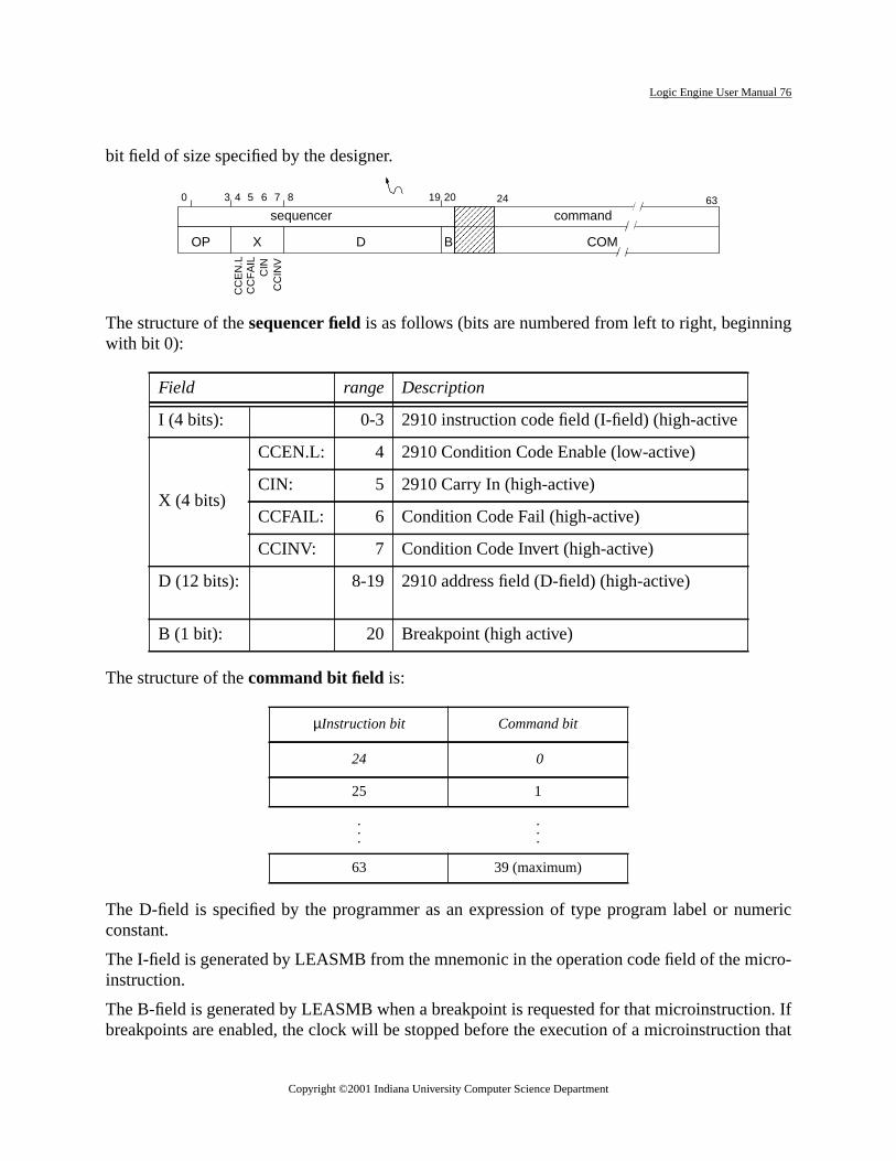
Logic Engine User Manual 76
g
meric
cro-
n. Ifn that
bit field of size specified by the designer.
The structure of thesequencer fieldis as follows (bits are numbered from left to right, beginninwith bit 0):
The structure of thecommand bit field is:
The D-field is specified by the programmer as an expression of type program label or nuconstant.
The I-field is generated by LEASMB from the mnemonic in the operation code field of the miinstruction.
The B-field is generated by LEASMB when a breakpoint is requested for that microinstructiobreakpoints are enabled, the clock will be stopped before the execution of a microinstructio
Field range Description
I (4 bits): 0-3 2910 instruction code field (I-field) (high-active
X (4 bits)
CCEN.L: 4 2910 Condition Code Enable (low-active)
CIN: 5 2910 Carry In (high-active)
CCFAIL: 6 Condition Code Fail (high-active)
CCINV: 7 Condition Code Invert (high-active)
D (12 bits): 8-19 2910 address field (D-field) (high-active)
B (1 bit): 20 Breakpoint (high active)
µInstruction bit Command bit
24 0
25 1
.
.
....
63 39 (maximum)
������
������sequencer
OP
4 20
command24
X
CC
INV
CIN
D B
0 3 19 635 6 7 8
CC
EN
.LC
CF
AIL
COM
Copyright ©2001 Indiana University Computer Science Department

Logic Engine User Manual 77
tax,gram-ithr with
FAIL.putif itstheitionns to
it to 1ify
ify a
it to 0inguc-
S orthenal
d by acon-Tolse).
true).n the
has this bit set.
The X-field
The bits in the X-field allow the programmer to exert, through the prescribed LEASMB syndetailed control over certain of the 2910 microprogram sequencer features. In normal proming, LEASMB will set the X-field bits automatically, and the programmer will not deal wthem. The use of the X-field is explained below. The discussion assumes you are familiathe operations of the 2910.
For each of its instructions, the 2910 sequencer provides two sub-operations, PASS andThe 2910 performs the PASS sub-operation if its CCEN.L input is high (false) or if its CC.L inis low (true). The 2910 performs the FAIL sub-operation under other conditions, namely,CCEN.L input is low (true) and its CC.L input is high (false). A designer may wish to controlchoice of sub-operation by forcing a PASS, forcing a FAIL, or allowing his Designer's CondCode input to determine the choice. The Logic Engine microinstruction provides the measelect each of these alternatives easily.
The designer may force the 2910 to select the PASS sub-operation by setting the CCEN.L b(false) in the microinstruction. (LEASMB performs this bit setting automatically if you specthe PASS option in the sequencer field of a symbolic microinstruction, or if you fail to specconditional clause.)
The designer may force the 2910 to select the FAIL sub-operation by setting the CCEN.L b(true) and the CCFAIL bit to 1 (true) in the microinstruction. (LEASMB performs this bit settautomatically if you specify the FAIL option in the sequencer field of a symbolic microinstrtion.)
The designer may allow his Designer's Condition Code signal to control the choice of PASFAIL sub-operation by setting the CCEN.L bit to 0 (true) and the CCFAIL bit to 0 (false) inmicroinstruction. (LEASMB performs this bit setting automatically if you specify the conditio"IF" clause in a symbolic microinstruction.)
Here is a summary of the bit values required to influence the choice of sub-operation:
The signal appearing on the Designer's Condition Code input may be low-active (assertelow voltage) or high-active (asserted by a high voltage). The Logic Engine microinstructiontains the CCINV bit to allow the programmer to specify which voltage polarity is in effect.specify that Designer's Condition Code is low-active, the designer may set CCINV to 0 (faTo specify that Designer's Condition Code is high-active, the designer may set CCINV to 1 ((LEASMB sets CCINV automatically, based on the declarations for the signal referenced i
CCEN.L CCFAIL
Force a PASS 1 (high, false) ---
Force a FAIL 0 (low, true) 1 (high, true)
Act on incoming Designer's Condition Code signal 0 (low, true) 0 (low, false)
Copyright ©2001 Indiana University Computer Science Department

Logic Engine User Manual 78
Code
illing is
lac-
esee
,
y
e.
m
.
.
"IF" clause of a symbolic microinstruction.)
In the Logic Engine, the logic equation governing the signal entering the 2910's Condition(CC.L) pin is
2910.CONDITION.CODE = (DESIGNER.CONDITION.CODExor CCINV) and CCFAIL
The CIN bit of the microinstruction connects directly to the 2910 CIN pin. Normally, this bit wbe a 1 (high, true), implying normal sequencing if a branch does not occur. Normal sequencinhibited if CIN is 0 (low, false). The programmer may override the normal value of CIN by ping a ‘/ ’ preceding the 2910 operation mnemonic..
2910 Signal Disposition
D (12 bits) Input. When PL.L is asserted, the Logic Engine pipeline register provides thbits. When PL.L is negated (i.e., when MAP.L or VECT.L is asserted), thdesigner's circuit must supply these bits.
I (4 bits) Input received from Logic Engine pipeline register.
CC.L Input received from Logic Engine. Derived from Designer's Condition CodeCCINV, and CCFAIL.
CCEN.L Input received from Logic Engine pipeline register.
CI Input received from Logic Engine pipeline register. Programmer may specifthe value through LEASMB.
RLD.L Input available at 2910 chip on Logic Engine board. Not used by Logic Engin
OE.L Input controlled exclusively by Logic Engine.
CP Input supplied exclusively by Logic Engine. Designer must supply the SysteClock from which CP is derived.
Y (12 bits) Output available on 60-pin flat-cable connector. Used by Logic Engine.
FULL.L Output available at 2910 chip on Logic Engine board. Used by Logic Engine
PL.L Output available at 2910 chip on Logic Engine board. Used by Logic Engine
MAP.L Output available on the 2910 PLD. Not used by Logic Engine.
VECT.L Output available on the 2910 PLD. Not used by Logic Engine.
Note: Directions are relative to the 2910.
Copyright ©2001 Indiana University Computer Science Department

Logic Engine User Manual 79
llowEPIe LEpow-LEPI
, the
e PCWithignaloard host.
e ref-e writ-ndingbled.ablinge are 4itch or
npute sig-
clocke LErd.
and 72itches,
I. Logic Engine Programmer's Interface
A. Introduction
The Logic Engine Programmer's Interface (LEPI) is a library of Microsoft C routines that athe user to monitor and control the LE board from the PC host. At the lowest level, the Lallows the user to read from the lights and write to the switches, buttons and pipeline of thboard. It can also control the clock on the LE board. At a higher level, the LEPI provides aerful way to name and invoke values onto groups of signals. Some of the many uses of theinclude, test vector generation, providing control signals to systems in lieu of microcodemigration of software simulations to hardware implementations and high level diagnostics.
B. How the LEPI Works
The LE board contains 128 lights, 16 toggle switches, 12 buttons and 40 bits of pipeline. Thhost has the ability to read from the lights and write to the switches, buttons and pipeline.this ability any signal that is wired to a light can be monitored by the PC host and any input sthat is wired to a switch, a button or the pipeline can be controlled by the PC host. The LE balso contains a clock which can be stopped, started and pulsed under the control of the PC
From the perspective of the host, the switches and buttons behave identically and will both bered to as switches in this document. Associated with each switch is a register which can bten by the PC host. The output of each switch is connected to the output of its corresporegister. Normally, the output of the register is disabled and the output of the switch is enaThe PC host can take control of the switches by disabling the output of the switches and enthe output of the registers. In addition to the 28 registers associated with the switches, therhidden registers which are accessible from the PC host which do not have an associated swbutton.
The pipeline is part of the microcontroller which is on the LE board and is used to control isignals to a design. The PC host can however, write directly to the pipeline to provide thesnals.
The PC host has the ability to stop a running clock, pulse a stopped clock, or start a stoppedby writing to the clocks control register. When the clock is stopped the clock controls on thboard are disabled. When the clock is running, its frequency is controlled from the LE boa
With these resources, the LE board has 128 parallel output signals which can be monitoredparallel input signals which can be controlled. Section 8.6 describes how to access the swbuttons and pipeline on the LE board.
Copyright ©2001 Indiana University Computer Science Department

Logic Engine User Manual 80
and
eons
s, but-al test
s notprop-
. This
entryhich
of
uppliedhes.
o theleast
C. Low Level Interface Routines
The low level interface includes routines to read the lights, write the switches and pipelinestop, start or pulse the clock. #include “/le/include/lelib.h”
#include “/le/include/lelib.h”
In order to use these routines, the file/<le>/include/lelib.h has to be included into the source filand the file/<le>/bin/lelib.lib has to be linked to the object files. See section 8.7 for instruction linking this library.
int initboard(void);
Configures the LE board so that the PC host can control the operation of the clock, switchetons and pipeline. It also determines on which port the board is attached and does a minimto determine if the board is functioning. If the board is present and functioninginitboard returns0 otherwise it returns a positive integer. If no board is found, it could mean that the board ipowered on, the interface cable is not connected properly or the LE board is not functioningerly. This function should be called before any of the LEPI functions are used.
void restoreboard(void);
Restores the LE board to a state in which the clock, switches and buttons are all enabledfunction should be called before exiting the user program.
void readlights(lights);
unsigned char *lights;
Reads the current value of all the lights. The values are stored in the user supplied arraylights.Each entry in the array holds eight bits representing the value of the lights. The first(lights[0]) contains lights 0-7, the second, lights 8-15 and so on up to the sixteenth entry wcontains lights 120-127. In each entry the lowest numbered light is the least significant bit.
int readlight(n);
int n;
Reads thenth 8-bit group of lights. Readlight(n) returns the value of the lightsn*8 throughn*8+7. The lowest numbered light is the least significant bit of the value returned. The valuencan range from 0 to 15. Ifn is outside this range, -1 is returned indicating an error.
void readswitches(switches);
unsigned char *switches;
Reads the current value of all the switches and buttons. The values are stored in the user sarrayswitches. Each entry in the array holds eight bits representing the value of the switcThe first entry (switches[0]) contains switches 0-7, the second, switches 8-15 and so on up tforth entry which contains switched 24-31. In each entry the lowest numbered switch is thesignificant bit.
Copyright ©2001 Indiana University Computer Science Department

Logic Engine User Manual 81
The
lds
31. In
i-
rstfifthignif-
after
int readswitch(n);
int n;
Reads thenth 8-bit group of switches.Readswitch(n) returns the value of the switchesn*8throughn*8+7. The lowest numbered switch is the least significant bit of the value returned.value ofn can range from 0 to 3. Ifn is outside this range, -1 is returned indicating an error.
void writeswitches(switches);
unsigned char *switches;
Writes the values in arrayswitchesto all the switches and buttons. Each entry in the array hoeight bits representing the value of the switches. The first entry (switches[0]) contains switches0-7, the second, switches 8-15 and so on up to the forth entry which contains switches 24-each entry the lowest numbered switch is the least significant bit.
int writeswitch(n,val);
int n;
unsigned char val;
Writes the valueval to thenth 8-bit group of switches.Writeswitch(n,val) writes the valuevalto the switchesn*8 throughn*8+7. The least significant bit ofval is written to the lowest num-bered switch. The value ofn can range from 0 to 3. Ifn is outside this range, -1 is returned indcating an error.
void writepipeline(pipe);
unsigned char *pipe;
Writes the values in arraypipe to the pipeline. Each entry in the array holds eight bits. The fientry (pipe[0]) contains bits 0-7 of the pipeline, the second, bits 8-15 and so on up to theentry which contains bits 32-39. In each entry the lowest numbered pipeline bit is the least sicant bit of the value.
int writepipe(n,val);
int n;
unsigned char val;
Writes the valueval to thenth 8-bit group of pipeline bits.Writepipe(n,val) writes the valuevalto the pipeline bitsn*8 throughn*8+7. The least significant bit ofval is written to the lowestnumbered pipeline bit. The value ofn can range from 0 to 4. Ifn is outside this range, -1 isreturned indicating an error.
void pulseclock(ticks);
int ticks;
Issuesticks number of clock pulses on the user clock. The clock is left in the stopped statethis function is called, so a value of 0 forticks will simply stop the clock.
void startclock(void);
Copyright ©2001 Indiana University Computer Science Department

pens.
tinered toutines:
Logic Engine User Manual 82
Puts the clock in the running state. If the clock was already in the running state, nothing hap
Fig. 1. is a small example of a C program that uses some of the low level routines. The routests one NAND gate (74ls00). It assumes that the inputs (pins 1 and 2) have been wiswitches 0 and 1 and the output (pin 3) has been wired to light 0. This example uses the roinitboard , restoreboard, writeswitch, andreadlight.
#include <stdio.h>#include “\le\include\lelib.h”
voidmain() { while(initboard()!=0) { /* initialize the board*/ fprintf(stderr,”LE Board not present or not functioning\n”); fprintf(stderr,”<Hit Enter key to continue>”); getchar(); } dotest();/* perform the test*/ restoreboard();/*restore the board*/ }
voiddotest() { static int expected[4] = {1,1,1,0}; /*Truth Table for 74ls00*/ int result; /*result of running test*/ int error; /*number of errors so far*/ unsigned char i; /*input value and loop index*/ error = 0; for(i=0;i<4;i++) { writeswitch(0,i);/*Present inputs to gate*/ result = readlight(0);/*Read output of gate*/ if(result != expected[i])
{ fprintf(stderr,”Error: Inputs: %d Result: %d Expected: %d\n”, i,result,!(i==3)); error++; } } fprintf(stderr,”The test completed with %d error(s)\n”,error);
}
Sample program using low-level LEPI routines
Copyright ©2001 Indiana University Computer Science Department

Logic Engine User Manual 83
e val-high
ationsdec-ith as can
s thehould
y theed
sem-
).
e
Thecates
. is
D. High Level Interface Routines
The high level interface includes routines to define field declarations and invocations, invokues onto the defined fields and read values from the defined fields. Table II. is a list of all thelevel routines available, including the signature and a description of each. The field declarand invocations are defined in a separate file. The syntax for this file is nearly identical to thelaration section of the LE Micro Assembly Language described in Chapter 5 of this manual wfew additions This file must be read by the user program before any of the high level routinebe used.
int initboard(void);
Besides initiating the board as described above in the low level routines, this routine initiatepipeline, switches and buttons to their default values as defined in the declaration file. It stherefore be called after callingdeclare.
int declare(filename);
char *filename;
Reads the named declaration file. This will construct an internal symbol table that is used binitboard , command, maskandreadval routines. The syntax of the declaration file is describin section XX. This routine should be called before theinitboard routine. The value returned isthe number of errors that occurred while parsing the declaration file.
int command(comlist[,arg]...);
char *comlist;
Thecommandroutine is used to assert values onto the defined field.Comlist is a string with thesame syntax as the command list portion of a microinstruction statement of the LE Micro Asbly Language as described in chapter 5 of this manual. In addition, thecomlist can contain for-mat specifications as in theprintf routine (See the Microsoft C Run-time Library ReferenceThe command routine asserts only the signals as defined incomlist. All other signals take ontheir default value. A negative value will be returned if a error occurred while parsingcomlistotherwise 0 will be returned.int mask(comlist[,arg]...);
char *comlist;
Themask routine is identical to thecommand routine with the exception that signals which arnot asserted as defined incomlist, remain at their current value.
int readval(field);
char *field;
The readval routine returns the value of the named field as defined in the declaration file.field argument is a string containing the name of the field to be read. A negative result indithat an error has occurred in parsingfield.
Fig. 2. is a small example of a C program that uses some of the high level routines and Fig. 3
Copyright ©2001 Indiana University Computer Science Department

Logic Engine User Manual 84
inputsutines:
modelure.s are
use ofuages, andFor a
the accompanying declaration file. The routine tests an ALU (74ls181). It assumes that theand outputs have been wired as defined in the declaration file. This example uses the rodeclare, initboard , restoreboard, command and readval. The testing algorithm used is topresent the device with all possible inputs, checking the outputs for each against a softwareof the device. The code for the software model (LS181 in fig. 2) is not shown in the figNotice that in the code of Fig. 2, there is no reference to light or switch numbers. All signalreferenced by name.
E. Declaration File Syntax
The declaration file is used to give logically names to a group of signals and to describe thethese signals. The syntax is similar to the declaration portion of the Micro Assembly Langdescribed in Chapter 5 of this manual with a few addtions to support the switches, buttonlights. The description of the syntax given here is only a subset of the complete syntax.complete description of the sytax, see Chapter 5.
The three basic directives used in the declaration file areCOM , LT , andSW. All of which havethe same syntax
A SW(0:3)B SW(4:7)S SW(8:11)M SW(12)C0 SW(13), T=%LF LT(8:12), T=%LHHHH
Copyright ©2001 Indiana University Computer Science Department

Logic Engine User Manual 85
#include <stdio.h>#include “lelib.h”
void main() { if(declare(“ls181.dec”)!=0) { fprintf(stderr,”Error: Declaration File\n”); exit(-1); } while(initboard()!=0) { fprintf(stderr,”LE Board not present or not functioning\n”); fprintf(stderr,”<Hit Enter key to continue> “); getchar(); } dotest(); restoreboard(); }
void dotest() { int a,b,s,m,c0,f,expected,errors;
errors = 0; for(s=0;s<16;s++){ fprintf(stderr,”Testing function %x for all possible inputs\n”,s); for(b=0;b<16;b++){ for(a=0;a<16;a++){ for(m=0;m<2;m++){ for(c0=0;c0<2;c0++){ command(“A=%d,B=%d,S=%d,M=%d,C0=%d”,a,b,s,m,c0); f = readval(“F”); expected = LS181f(a,b,s,m,c0);
if(f != expected){ fprintf(stderr, “Error: A=%x,B=%x,S=%x,M=%x,C0=%x->F=%x:Expected:%x\n” ,a,b,s,m,c0,f,expected); errors++; printf(“test>”);if(getchar()==’q’) exit(-1); } } } } } } fprintf(stderr,”The test completed with %d error(s)\n”,errors);}
Sample program using high-level LEPI routines
Copyright ©2001 Indiana University Computer Science Department

Logic Engine User Manual 86
se
<name> <dir> <range> [, <truth values>] [,<default values>
where]
TheCOM andSW directives both define input fields to the board. The name defined by thedirectives can be used incommand or mask statements. TheLT directives define output fieldsfrom the board. The name defined by these directives can be used inreadval statements.
<name> ::=
A string of any length containing, upper orlower case letters, numerals, "_", or ".".The first character must be a letter. Thisdefines the name of the field.
<dir> ::= COM, LT, orSW The directive defines the type of field.
<range> ::= ( n,m) n and m are integers and n is less than m.The range defines the signals in the field.
::= ( n)
<truth values> ::= T=<numeric value> The truth value defines the interpretationof the voltage of each signal in the field. Ifabsent, each signal is assumed to be truehigh.
::= T=<voltage value>
<default values> ::= D=<numeric value> The default value defines the value eachsignal gets when it is not asserted. Usedonly for COMandSWdirectives. If absent,the default for each signal will be a lowvoltage forVOLTAGE mode and a falsevalue forLOGIC mode. See the MODEdirective below.
::= D=<voltage value>
::= D=<logic value>
<numeric value> ::= [0-9]* decimal value
::= $[0-9a-fA -F]* hexadecimal value
::= %[01 ]* binary value
<voltage value> ::= %[HL]* high and low voltage values
<logic values> ::= %[TF]* true and false logic values
Copyright ©2001 Indiana University Computer Science Department

Logic Engine User Manual 87
iffer-how
ee the
t
-0
F. Nomenclature
The naming and numbering of the switches, lights, and pipeline for the software is slightly dent from that of the hardware and can be a point of confusion. The following tables describethey relate to each other. For exact location of these points on the Logic Engine board, sLogic Engine Board User Manual.:
Table 5: Switches
Type Switch
Switch
Switch
Switch
Hid-den
Push-But-ton
Push-But-ton
Hid-den
Push-But-ton
Push-But-ton
num-ber-ing
Soft-ware
31-28
27-24
23-20
19-16
15-14
13-12
11-8 7-6 5-4 3-0
Hardware
S15-S12
S11-S8
S7-S4
S3-S0
B15-B14
B13-B12
B11-B8
B7-B6
B5-B4
B3-B0
IC/pin
XX/20-17
XX/16-13
XX/20-17
XX/16-13
XX/20-19
XX/18-17
XX/16-13
XX/20-19
XX/18-17
XX/16-13
Table 6: Lights 127-64
Type Light Light Light Light Light Light Light Light
num-bering
Soft-ware
127-120
119-112
111-104
103-96 95-88 87-80 79-72 71-64
Hard-ware
L127-L120
L119-L112
L111-L104
L103-L96
L95-L88
L87-L80
L79-L72
L71-L64
IC/pin XX/2-9 XX/2-9 XX/2-9 XX/2-9 XX/2-9 XX/2-9 XX/2-9 XX/2-9
Table 7: Lights 0-63
Type Light Light Light Light Light Light Light Ligh
numbering
Soft-ware
63-56 55-48 47-40 39-32 31-24 23-16 15-8 7
Hard-ware
L63-L56
L55-L48
L47-L40
L39-L32
L31-L24
L23-L16
L15-L8 L7-L0
IC/pin XX/2-9 XX/2-9 XX/2-9 XX/2-9 XX/2-9 XX/2-9 XX/2-9 XX/2-9
Copyright ©2001 Indiana University Computer Science Department

Logic Engine User Manual 88
e
2
Table 8: Pipeline
Type Pipeline Pipeline Pipeline Pipeline Pipelin
numbering
Software 39-32 31-24 23-16 15-8 7-0
Hardware P39-P32 P31-P24 P23-P16 P15-P8 P7-P0
IC/pin XX/19-12 XX/19-12 XX/19-12 XX/19-12 XX/19-1
Copyright ©2001 Indiana University Computer Science Department

Logic Engine User Manual 89
odelcom-
G. Linking the Library
In order use the LE PI library, the source files must be compiled using the large memory mand then linked with the library as illustrated in the example below. For more details aboutpiling and linking see the Microsoft C Compiler User's Guide and Reference Manual.
Compile:cl /c /AL file1.ccl /c /AL file2.c
Link:link file1.obj file2.obj, prog.exe, prog.map, lelib.lib ;
Copyright ©2001 Indiana University Computer Science Department