Log book
26
THE UNIVERSITY OF MELBOURNE Constructing Environments Log Book Name : Trishya John Student ID Number: 699579
description
Constructing Environments A01 Interim Submission
Transcript of Log book

THE UNIVERSITY OF MELBOURNE
Constructing Environments
Log Book
Name : Trishya John
Student ID Number: 699579

1
Week 1 – Introduction to Construction
Knowledge maps
Loads on buildings (Ching, 2008)
Structural forces (Newton, 2014)

2
Materials (Newton, 2014)

3
Site Analysis
(Ching, 2008)

4
Theatre Session
We were introduced to the concept of loads on buildings in our first theatre session where we
were given a single sheet of blank A4 paper and tape and asked to build a structure that can
support a brick using only those materials. I formed a four point structure as shown below, which
I strengthened by folding repetitively. I was unable to test the structure at the lecture, so I
performed a test once I got back home by checking if the paper structure was able to support the
load of all my textbooks.
It was able to support my textbooks when the
thicker side of the structure made contact with
the ground, but not when the thinner side made
contact with the ground. One of the things that I was able to learn from this experience was that
it was crucial for a structure to have a very strong base in order to support an immense load. I
also realized that one of the reasons why my structure was successful was because the
symmetrical shape of it may have enabled an even distribution of the load of the textbooks
throughout the structure. These were some of the key elements that I tried to apply to our
structure that was built during the studio session.
Shape allows an even
distribution of the load of the
textbooks throughout the
structure
5
Studio Session
Construction procedure
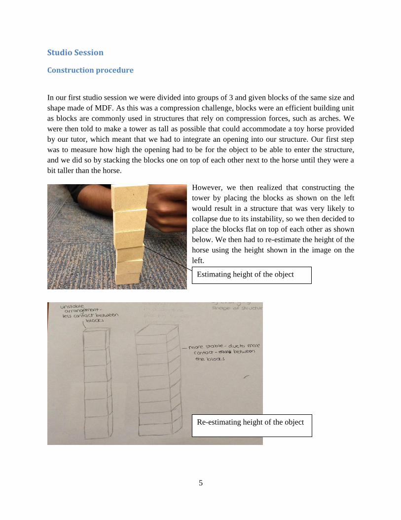
In our first studio session we were divided into groups of 3 and given blocks of the same size and
shape made of MDF. As this was a compression challenge, blocks were an efficient building unit
as blocks are commonly used in structures that rely on compression forces, such as arches. We
were then told to make a tower as tall as possible that could accommodate a toy horse provided
by our tutor, which meant that we had to integrate an opening into our structure. Our first step
was to measure how high the opening had to be for the object to be able to enter the structure,
and we did so by stacking the blocks one on top of each other next to the horse until they were a
bit taller than the horse.
However, we then realized that constructing the
tower by placing the blocks as shown on the left
would result in a structure that was very likely to
collapse due to its instability, so we then decided to
place the blocks flat on top of each other as shown
below. We then had to re-estimate the height of the
horse using the height shown in the image on the
left.
Estimating height of the object
Re-estimating height of the object

6
We then decided to slightly change the laying of the blocks and place them the conventional way
bricks were laid in a building instead of merely stacking them one on top of each other. This
would have been more stable than originally planned, as the load from a block will be transferred
to two bricks below it instead of just one and thus be spread out more evenly.
We then started to build the structure
as shown below. Our aim was to pack
the blocks as tightly as possible in the
first ten rows to create a stable base
and then decide on how to change the
way the blocks were laid once the
structure gained a reasonable height.
Packing the blocks tightly together will
result in more blocks being laid at the
base, which then increases the
compression forces, causing the blocks
to be compact. This is what will ensure
stability for the whole structure.
Original block laying technique Modified block laying technique
Foundation of the structure
Aimed height of the opening
7
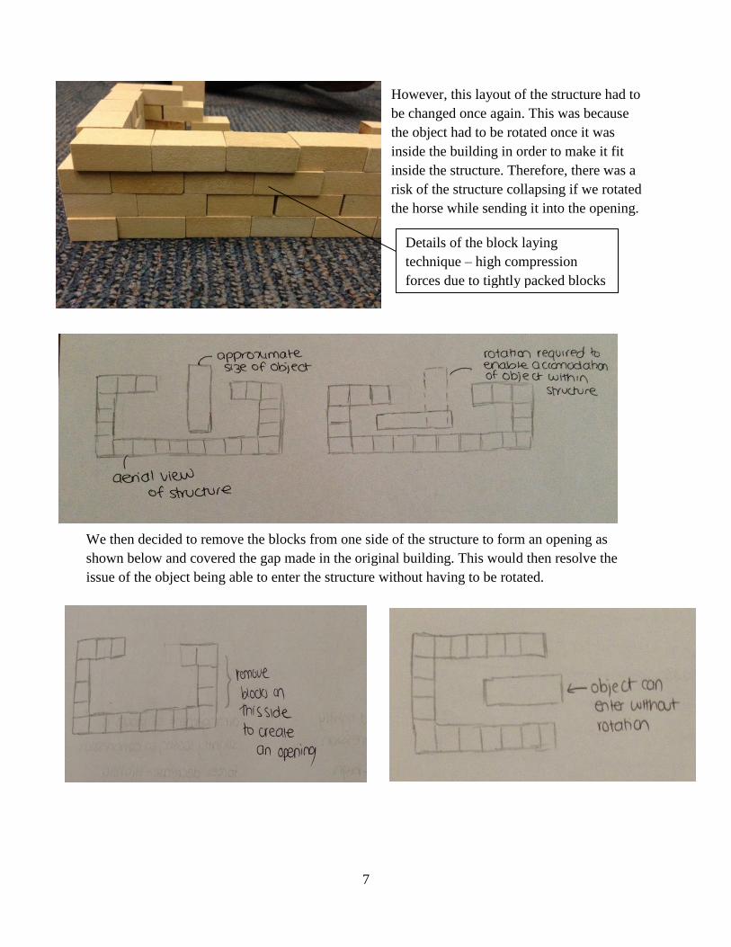
However, this layout of the structure had to
be changed once again. This was because
the object had to be rotated once it was
inside the building in order to make it fit
inside the structure. Therefore, there was a
risk of the structure collapsing if we rotated
the horse while sending it into the opening.
We then decided to remove the blocks from one side of the structure to form an opening as
shown below and covered the gap made in the original building. This would then resolve the
issue of the object being able to enter the structure without having to be rotated.
Details of the block laying
technique – high compression
forces due to tightly packed blocks
8
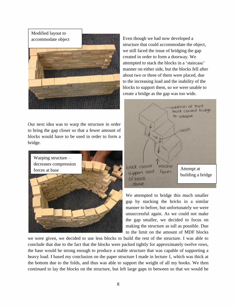
Even though we had now developed a
structure that could accommodate the object,
we still faced the issue of bridging the gap
created in order to form a doorway. We
attempted to stack the blocks in a ‘staircase’
manner on either side, but the blocks fell after
about two or three of them were placed, due
to the increasing load and the inability of the
blocks to support them, so we were unable to
create a bridge as the gap was too wide.
Our next idea was to warp the structure in order
to bring the gap closer so that a fewer amount of
blocks would have to be used in order to form a
bridge.
We attempted to bridge this much smaller
gap by stacking the bricks in a similar
manner to before, but unfortunately we were
unsuccessful again. As we could not make
the gap smaller, we decided to focus on
making the structure as tall as possible. Due
to the limit on the amount of MDF blocks
we were given, we decided to use less blocks to build the rest of the structure. I was able to
conclude that due to the fact that the blocks were packed tightly for approximately twelve rows,
the base would be strong enough to produce a stable structure that was capable of supporting a
heavy load. I based my conclusion on the paper structure I made in lecture 1, which was thick at
the bottom due to the folds, and thus was able to support the weight of all my books. We then
continued to lay the blocks on the structure, but left large gaps in between so that we would be
Attempt at
building a bridge
Modified layout to
accommodate object
Warping structure –
decreases compression
forces at base
9
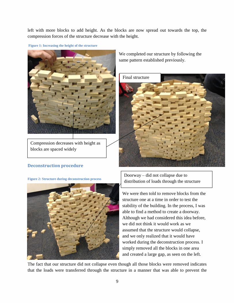
left with more blocks to add height. As the blocks are now spread out towards the top, the
compression forces of the structure decrease with the height.
Figure 1: Increasing the height of the structure
We completed our structure by following the
same pattern established previously.
Deconstruction procedure
Figure 2: Structure during deconstruction process
We were then told to remove blocks from the
structure one at a time in order to test the
stability of the building. In the process, I was
able to find a method to create a doorway.
Although we had considered this idea before,
we did not think it would work as we
assumed that the structure would collapse,
and we only realized that it would have
worked during the deconstruction process. I
simply removed all the blocks in one area
and created a large gap, as seen on the left.
The fact that our structure did not collapse even though all those blocks were removed indicates
that the loads were transferred through the structure in a manner that was able to prevent the
Compression decreases with height as
blocks are spaced widely
Final structure
Doorway – did not collapse due to
distribution of loads through the structure

10
structure from collapsing. It is possible that our structure may have been able to support a
heavier load, if it had remained in a rectangular shape. This final structure may have encountered
difficulties with doing so because warping the structure pushed the blocks out of proportion in
the base, which may have reduced the compression forces that would have been much stronger if
the blocks were packed tightly together.
Figure 3: Load path diagram of structure with a few blocks removed
Figure 4: Comparison of compression forces between original structure and warped structure

11
Comparison with other groups
This group had built a structure that was most
similar to ours in terms of the way they laid
the blocks, and the fact that they packed the
blocks tightly for the first few rows and
incorporated gaps in the higher rows. The
only differences were the shape of the
building and the fact that they had managed
to successfully integrate a doorway into their
structure.
This was another structure created by one of
the groups, which had a very different block
laying technique and shape compared to the
structures of the other groups. It seems as
though their technique of laying blocks,
although aesthetically appealing, may have
used a relatively larger amount of blocks
compared to the conventional brick laying
technique that all the other groups adapted.
Even though their structure was able to
accommodate the object, they too appeared
to be unsuccessful in bridging the gap.
Strong compression forces enabled
structure to support a load of over
5kg, which was done near the end
of the studio session
The blocks are packed tightly
together, which will increase the
compression forces in the structure

12
Although the block laying technique is not
very visible in this photograph, it appears
that they adopted a similar method to our
structure. However, it appears that they
might have encountered difficulties during
the construction process as they too were
unsuccessful in creating a doorway, and
were not able to create a tall structure. The
blocks appear to be packed tightly together
and they have followed this method to
create the entire structure, which means that
the compression forces will be high.
Week 2 – Structural Loads and Forces
Knowledge maps
Structural systems
(Newton, 2014)
Structural joints
(Newton, 2014)
13
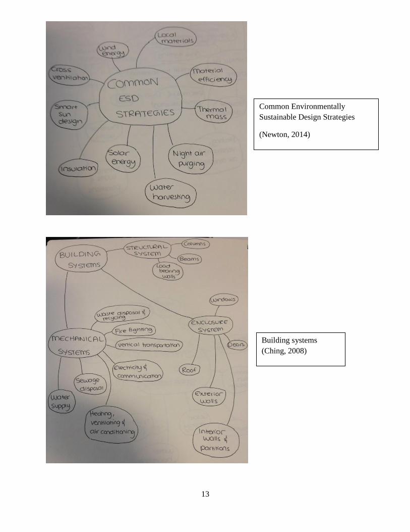
Common Environmentally
Sustainable Design Strategies
(Newton, 2014)
Building systems
(Ching, 2008)
14
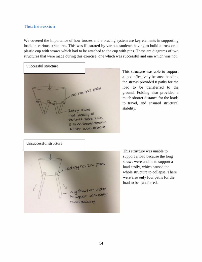
Theatre session
We covered the importance of how trusses and a bracing system are key elements in supporting
loads in various structures. This was illustrated by various students having to build a truss on a
plastic cup with straws which had to be attached to the cup with pins. These are diagrams of two
structures that were made during this exercise, one which was successful and one which was not.
This structure was able to support
a load effectively because bending
the straws provided 8 paths for the
load to be transferred to the
ground. Folding also provided a
much shorter distance for the loads
to travel, and ensured structural
stability.
This structure was unable to
support a load because the long
straws were unable to support a
load easily, which caused the
whole structure to collapse. There
were also only four paths for the
load to be transferred.
Successful structure
Unsuccessful structure

15
The unsuccessful structure can be improved by introducing a bracing system as shown in the
figure above. The system is in the shape of triangles, which is a difficult shape to distort, and
therefore adds more stability to the system. It also provides more paths for the loads to be
transferred to the ground.
The concepts illustrated in the lecture were useful for the frame challenge in the studio session,
as they illustrated the different ways in which long, thin members could be used to effectively
carry and transfer loads.
Studio session
Construction procedure
This week’s studio introduced the concept of a frame structure, and to illustrate this, we were
told to build a frame tower out of only 20 strips of cut balsa wood in groups of 3. The tower had
to be as tall as possible, and we were encouraged to experiment with different types of joints. We
were told that the towers would have a load placed on it once they were completed to see at
which points they fail. Balsa wood was an efficient material for this challenge as the strips were
light and had a low density, which are properties that would have been needed to make a frame
structure. In order to save strips of balsa wood, we decided to make the tower in the shape of a
triangle instead of a square or rectangle. We cut 3 pieces of wood, of 20cm each, and used them
to form an equilateral triangle for the base. Then, we joined three strips of wood to each of the
corners of the triangle.
How unsuccessful structure can be
improved

16
We then cut a second triangle with sides
measuring 20cm and joined it with the three
strips of wood that were stuck onto the first
triangle.
The strips of wood were joined together
by masking tape, which, in the context
of this structure, can be considered a
fixed joint. A fixed joint resists rotation
and translation in any direction, and
provides force and moment resistance
(Ching, 2008), and as the structure was
relatively stable with an additional
successive level, we decided to
continue using fixed joints.
Sketch of structure we
wanted
Foundation of
structure

17
However, as the structure began to increase in height, we
found that we had to add pins to the joints, thus creating pin
joints, along with the fixed joints, as strips of joined balsa
wood kept detaching, which suggested that just fixed joints
were not strong enough to hold the members together. We
joined the strips of wood with a pin, and then wrapped the
pin with masking tape.
Fixed joint
Details of fixed joint
Structure is stable but a
slight tilt can be observed
due to weak joints

18
Although we assumed that our
combination of pin and fixed joints
were strong enough to keep the
members in place, the tower began
to twist and lean as it increased in
height, possibly due to the
increasing load of the structure.
This was an indication that perhaps
the joints may have not been
efficient enough to transfer the
loads, possibly due to the way we
had attached the members. The
manner in which forces are
transferred from one structural
element to the next and how a
structural system performs depends
on the types of joints used, to a
large extent (Ching, 2008). The addition of the pin may have also caused the member to fold
backwards, based on the way we attached it, which may have also been a factor in causing the
structure to twist because the joints were not stable enough to transfer the loads.
The members were also
rectangular in shape, which
results in uneven distribution
of the load through the strips
of balsa wood. This would
have also been one of the
factors that caused the
torsion of the member,
resulting in the whole
structure twisting. If the
members were in the shape
of a square, there would have
been a more even
distribution of the load,
resulting in less torsion.
Details of pin joint
Load through individual members
19
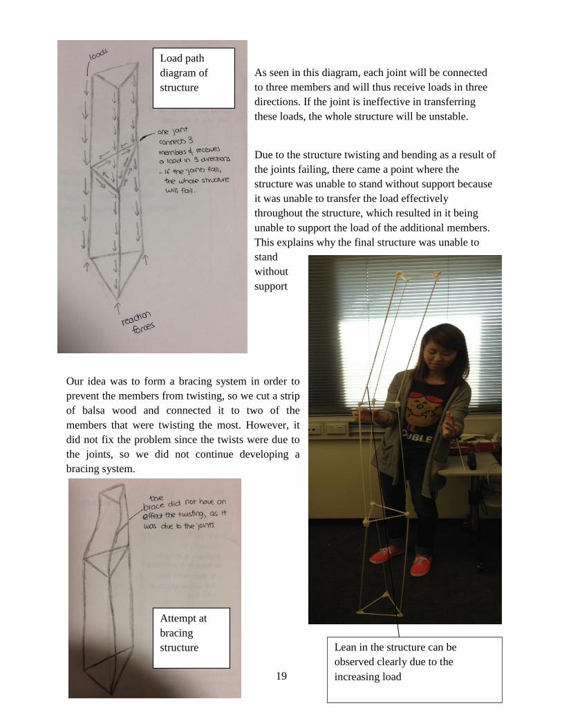
As seen in this diagram, each joint will be connected
to three members and will thus receive loads in three
directions. If the joint is ineffective in transferring
these loads, the whole structure will be unstable.
Due to the structure twisting and bending as a result of
the joints failing, there came a point where the
structure was unable to stand without support because
it was unable to transfer the load effectively
throughout the structure, which resulted in it being
unable to support the load of the additional members.
This explains why the final structure was unable to
stand
without
support
Our idea was to form a bracing system in order to
prevent the members from twisting, so we cut a strip
of balsa wood and connected it to two of the
members that were twisting the most. However, it
did not fix the problem since the twists were due to
the joints, so we did not continue developing a
bracing system.
Load path
diagram of
structure
Attempt at
bracing
structure Lean in the structure can be
observed clearly due to the
increasing load

20
We finally added 3 more members to the 3rd triangle (excluding triangle made for the base) and
joined them at the ends. These are images of the final structure which was, as seen below, unable
to stand without being supported.
Deconstruction procedure
The structures then had a load applied to them, in order to estimate at which points they started
to fail.
Figure 5: Deconstruction procedure
As seen in the picture, the structure was bending
at the joints when a load was applied. It was
mentioned before that the purpose of a fixed joint
was to prevent rotation of the members, but ours
failed to do so because we connected the
members incorrectly. This was why the structure
was bending at the joints.
Structure without a support
system
Point at which
structure was
unable to support
itself
Structure with a
support system
Bending occurring at the joints
when a load is applied – joint
should have resisted load

21
As the load increased, one of the members
that were joined at the second triangle
snapped at its mid-point. This was because
the increasing load was causing an increase
in the reaction force that was acting on the
member. The two forces met at the middle,
which then caused the structure to snap at
that point.
Load path diagram of a section of
structure during deconstruction
process
22
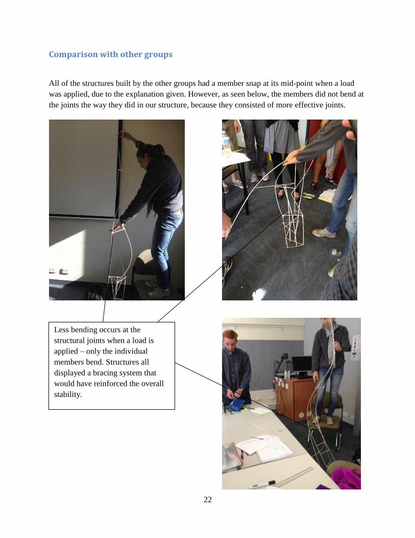
Comparison with other groups
All of the structures built by the other groups had a member snap at its mid-point when a load
was applied, due to the explanation given. However, as seen below, the members did not bend at
the joints the way they did in our structure, because they consisted of more effective joints.
Less bending occurs at the
structural joints when a load is
applied – only the individual
members bend. Structures all
displayed a bracing system that
would have reinforced the overall
stability.

23
Glossary of Terms (Ching, 2008)
Beam – rigid structural members designed to carry and transfer transverse loads across space to
supporting elements.
Brace - A diagonal tie that interconnects scaffold members (WebFinance Inc, 2014)
Carbon footprint – measure of the amount of greenhouse gases generated during the
fabrication, transportation and use of a particular product
Columns – rigid, relatively slender structural members designed primarily to support axial
compressive loads applied to the ends of the members
Collinear forces – occur along a straight line, the vector sum of which is the algebraic sum of
the magnitudes of the forces, acting along the same line of action
Compression forces – an external load pushing on a structural member, resulting on the
shortening of the material (Newton, 2014)
Concurrent forces – have lines of action intersecting at a common point, the vector sum of
which is equivalent to and produces the same effect on a rigid body as the application of the
vectors of the several forces
Dead loads – static loads acting vertically downward on a structure, comprising the self-weight
of the structure and weight of building elements fixtures and equipment firmly attached to it
Dynamic loads – loads that are applied suddenly to a structure, often with rapid changes in
magnitude and point of application
Fixed joint – maintains the angular relationship between the joined elements, restrains rotation
and translation in any direction, and provides both force and moment resistance.
Frame – an assembly of vertical and horizontal structural members (WebFinance Inc, 2014)
Impact loads – kinetic loads of short duration (moving vehicles, equipment and machinery)
Live loads – any moving or movable loads on a structure resulting from occupancy, collected
snow and water, or moving equipment
Load path – the route a load takes through a structural system to reach the ground
Masonry – building with units of various natural or manufactured products, usually with the use
of mortar as a bonding agent

24
Non-current forces – have lines of action that do not intersect at a common point, the vector
sum of which is a single force that would cause the same translation and rotation of a body as the
set of original forces
Occupancy loads – result from the weight of people, furniture, stored material and other similar
items in a building
Pin joints – allow rotation but resist translation in any direction
Point load– A concentrated load in a specific position on a structural member (WebFinance Inc,
2014)
Rain loads – accumulation of water on a roof because of its form, deflection, or the clogging of
its drainage system
Reaction force – equal and opposite forces that resist an applied force
Recyclability – potential for a product / material to be reused or transformed into a new product
Roller joints – allows rotation but resists translation in a direction perpendicular into or away
from their faces
Site analysis – the process of studying the contextual forces that influence how we might situate
a building, lay out and orient its spaces, shape and articulate its enclosure, and establish its
relationship to the landscape
Snow loads – created by the weight of snow accumulating on the roof
Static loads – loads that are applied slowly to a structure until it reaches its peak value without
fluctuating rapidly in magnitude or position
Stability – the measure of the ability of a structure to withstand overturning, sliding, buckling or
collapsing (WebFinance Inc, 2014)
Structural joints – connectors used to joint structural elements
Tension forces – external load pulling on a structural member, causing the material to elongate
(Newton, 2014)
Wind loads – forces exerted by the kinetic energy of a moving mass of air, assumed to come
from any horizontal direction

25
References Ching, F. D. (2008). Building Construction Illustrated (4th ed.). Hoboken, New Jersey : John
Wiley & Sons.
Newton, Claire (2014). Introduction To Materials. Constructing Environments.
Newton, Claire (2014). Basic Structural Forces. Constructing Environments
Newton, Claire (2014). Structural Systems and Forms. Constructing Environments
Newton, Claire (2014). ESD And Selecting Materials. Constructing Environments
Newton, Claire (2014). Structural Connections. Constructing Environments
WebFinance Inc. (2014). Dictionary of Construction.com. Retrieved March 15, 2014, from
http://www.dictionaryofconstruction.com/