LOCATING NEARBY CLOUD TO GROUND LIGHTNING FROM...
39
LOCATING NEARBY CLOUD TO GROUND LIGHTNING FROM MEASUREMENTS OF INDUCED VOLTAGES ON OVERHEAD CONDUCTOR'S ENDS ZURAIMY BIN ADZIS A thesis submitted in fulfilment of the requirements for the award of the degree of Doctor of Philosophy (Electrical Engineering) Faculty of Electrical Engineering Universiti Teknologi Malaysia APRIL 2012
Transcript of LOCATING NEARBY CLOUD TO GROUND LIGHTNING FROM...

LOCATING NEARBY CLOUD TO GROUND LIGHTNING FROM
MEASUREMENTS OF INDUCED VOLTAGES ON OVERHEAD
CONDUCTOR'S ENDS
ZURAIMY BIN ADZIS
A thesis submitted in fulfilment of the
requirements for the award of the degree of
Doctor of Philosophy (Electrical Engineering)
Faculty of Electrical Engineering
Universiti Teknologi Malaysia
APRIL 2012
iii
ACKNOWLEDGEMENT
First of all, I am greatly thankful to Allah SWT for giving me the opportunity to conduct this study and ideas that comes with it. I would like to express my gratitude and thanks to my supervisor, Associate Professor Dr. Zulkurnain Abdul Malek for giving his valuable time, advice and continuous encouragement towards the completion of my project from beginning till the end. His patience is a virtue.
Secondly, my appreciation goes to my family, who has been so tolerant and supporting me all these years. Thanks for their encouragement, love, and emotional support that they had given to me.
I also would like to extend my appreciation to everyone around me, those who taught me lessons in research and in life. This appreciation is also extended to those I have never met, but their knowledge is passed on to me through their publication, their contributions to whatever media available in the effort to promote knowledge. ‘Kudos’ to them and I wish to be able to contribute and have the impact to others just as they have done to me.

iv
ABSTRACT
The lightning locating methods are applied to large areas with an array of sensors that is connected to a central computer, using either Time of Arrival techniques or Magnetic Direction Finding techniques, or both. However, a relatively significant error would be present in the assessment of ground flash density for a much smaller area due to the weaknesses of the location accuracy for smaller areas. This thesis introduces an alternative method of locating nearby lightning, which maximized the benefits of the induced voltages at terminated ends of an overhead conductor. It utilises the time differences to peak (∆tp) and percentage differences of peak voltages (∆vp), between lightning induced voltages (LIV) at both ends. Research work includes field measurements of LIV on ends of a 210 meter overhead conductor and computations of the same. Computation using established electromagnetic mathematical model programmed in C++ in time domain is presented and discussed. Results were validated against other researchers’ work and measurements. A parametric study from the model with varying parameters in inducing voltage at both ends is also presented. Further analysis shows that ∆tp and ∆vp of the conductors were not significantly affected by the changes of the return stroke peak current, uniform finite ground conductivity, conductor’s intrinsic inductance and terminating resistances. The mathematical model was also extended to longer conductors (350 meter span ground wires and 5 mile distribution cable) by taking into account of the effects of finite ground conductivity and earth return current. The results thus support the applicability of the proposed method. It is also shown that measurement of the induced voltage at both ends of the overhead conductor, with particular attention to ∆tp and ∆vp enables the inference of nearby cloud to ground (CG) lightning location. The modelling work is currently limited to vertically aligned CG lightning, un-attenuated and undistorted lightning return stroke current through the lightning channel with a uniform velocity and interference free.

v
ABSTRAK
Kaedah mengesan lokasi kilat diaplikasikan untuk kawasan yang besar
dengan tatasusunan penderia yang bersambung kepada sebuah komputer pusat, mengguna pakai samada kaedah Waktu Ketibaan atau Pencari Arah Magnetik, atau kedua-duanya secara serentak. Namun ralat yang agak ketara wujud dalam penilaian ketumpatan kilat ke bumi untuk kawasan yang lebih kecil disebabkan kelemahan kejituan pengesan lokasi sistem tersebut untuk kawasan yang kecil. Tesis ini memperkenalkan kaedah lain dalam mengesan lokasi kilat berdekatan, memanfaatkan voltan teraruh pada hujung pengalir tergantung yang ditamatkan dengan perintang. Ia menggunakan perbezaan masa untuk memuncak (∆tp), dan peratusan perbezaan puncak voltan (∆vp) yang teraruh akibat kilat (LIV) di antara kedua-dua hujung pengalir tersebut. Kerja-kerja penyelidikan termasuk pengukuran tapak LIV pada pengalir tergantung sepanjang 210 meter dan juga pengiraan berbantu komputer untuk pengukuran tersebut. Pengiraan berbantu komputer menggunapakai model matematik elektromagnet yang diiktiraf, diaturcara menggunakan C++ dalam domain masa juga dibentang dan dibincangkan. Hasil keputusan dari pengaturcaraan dibanding dengan keputusan dan pengukuran dari penyelidik-penyelidik lain. Kajian parametrik dari model pengaturcaraan dengan parameter yang berbeza-beza dalam mengaruhkan voltan pada kedua-dua hujung pengalir juga dibentangkan. Analisa lanjut menunjukkan bahawa ∆tp dan ∆vp yang dicatatkan diantara kedua hujung pengalir tidak berubah secara ketara dengan perubahan arus puncak lejang kembali, keberaliran tanah terbatas yang seragam, kearuhan hakiki pengalir dan juga nilai rintangan penamatan. Kaedah ini juga dilanjutkan kepada pengalir yang lebih panjang (wayar bumi 350 meter pada sistem penghantaran elektrik dan juga wayar pengagihan sepanjang 5 batu) dengan mengambilkira kesan keberaliran tanah yang terbatas (bukan infiniti) dan arus pulang melalui bumi. Keputusannya memberangsangkan sekali gus menyokong kebolehgunaan kaedah baru ini. Juga ditunjukkan bahawa pengukuran voltan teraruh pada kedua-dua hujung pengalir tergantung dengan perhatian khusus kepada ∆tp dan ∆vp membenarkan anggaran lokasi kilat awan ke bumi (CG) yang berdekatan. Kerja permodelan ini terbatas kepada kilat CG yang menegak, arus kilat lejang kembalinya yang melalui saluran kilat tidak terlemah atau terherot dengan halaju yang seragam dan bebas gangguan.

vi
TABLE OF CONTENTS
CHAPTER TITLE PAGE
DECLARATION ii
ACKNOWLEDGEMENT iii
ABSTRACT iv
ABSTRAK v
TABLE OF CONTENTS vi
LIST OF TABLES viii
LIST OF FIGURES ix
LIST OF ABBREVIATIONS xvii
LIST OF APPENDICES xix
1 INTRODUCTION 1 1.1 Overview 1
1.2 Problem Statement 3
1.3 Objective 6
1.4 Scope 7
1.5 Contributions of the research 8
1.6 Structure of thesis 9
2 LITERATURE STUDY 11
2.1 Lightning phenomenon 11
2.2 Lightning induced voltages on ends of 14
overhead conductors
2.3 Lightning locating methods 20
2.4 Modeling of induced voltage on ends 31
of an overhead conductor

vii
3 METHODOLOGY 42
3.1 Introduction 42
3.2 Research flowchart 43 3.3 Experimental works 48
3.4 On-site measurement works 50
3.5 Mathematical modeling work 53
3.6 Flow of the calculation program 56
3.7 Summary 73
4 RESULTS 75
4.1 Introduction 75
4.2 Experimental results 76
4.3 On-site measurement results 81
4.4 Mathematical modeling results 83
4.5 Overall discussion 131
5 DISCUSSION 133
5.1 Introduction 133
5.2 Further discussion on the proposed method 133
5.2.1 Comparison of modeling result with 134
results of other established work
5.3 The originality of the proposed method 138
5.4 Discussions on shortfalls of the proposed method 140
5.5 Preliminary solutions for the shortfalls of the 146
proposed method
5.6 Summary 152
6 CONCLUSION AND RECOMMENDATIONS 154
6.1 Conclusion 154
6.2 Achievement of the objectives 156
6.3 Recommendations 157
REFERENCES 159
Appendices A-D 170-192

viii
LIST OF TABLES
TABLE NO TITLE PAGE
3.1 Parameter values set for the modeling of
telecommunication cable 68
3.2 Parameter values set for the modeling of the
ground wire of a 315kV transmission system 70
3.3 Parameter values set for the modeling of single
phase cable of an 11kV distribution system cable 72
4.1 Tabulation of measured peak amplitude
difference between both ends 79
4.2 Tabulation of measured difference of time to
peak 80
4.3 The parameters of the lightning current imposed
in the modeling exercise 84
5.1 Quantitative analysis of key parameters between
modeling and [25] 135
5.2 Quantitative analysis of amplitudes between
modeling and [25] 136
ix
LIST OF FIGURES
FIGURE NO TITLE PAGE NO
2.1 The polarities in pockets of thunderstorm cloud
with updrafts from [6] 12
2.2 Comparison between measurement on reduced-
scale model and simulation results 16
2.3 The shape of a 1.2/50µs lightning current 17
2.4 Adopted from Figure 1 of [25] 18
2.5 The FDTD coupling model from Agrawal [29] 19
2.6 A typical CG waveform recorded by DTF and its
accompanying table from [43] 23
2.7 Intersecting parabolas from 3 TOA sensors 24
2.8 Error regions from Sattari [45] 25
2.9 95% confidence regions from Hu [46] 25
2.10 Topographical distribution of location accuracy
from Hu [47]
26
2.11 Pictures of a crossed loop antenna 27
2.12 Detection efficiency curves for northern Ontario
network [48]
28
2.13 The geometry of the system modeled adopted
from [27]
32
3.1 Research methodology flowchart 44
3.2 The diagram of experiment setup 49
3.3 Photo of experiment setup 49
3.4 Location of current rod being tested 50
3.5
Cloud to ground lightning strike model adopted
for developing the localized lightning locating
system (LLLS) from [30]
51

x
3.6 The LLLS construction lay out from [2] 51
3.7 Plan view of cables for measurement from [2] 52
3.8 Flowchart of modeling main program 57
3.9 A partial diagram of the 32 segments of the
overhead conductor applied in the modeling 59
3.10 Flowchart of modeling subroutine ‘voltcal’ 60
3.11 Flowchart of modeling subroutine ‘eh’ and ‘ev’ 64
3.12 Flowchart of modeling subroutine ‘currg’ and
‘currg_i’ 66
3.13 The equivalent circuit of telecommunication
cable modeling 68
3.14 The equivalent circuit of ground wire modeling 70
3.15 The equivalent circuit of single distribution cable modeling
73
4.1(a) Waveform at End A for coordinate (150, 30) 77
4.1(b) Waveform at End A for coordinate (150,-30)
77
4.1(c) Waveform at End B for coordinate (150, 30)
77
4.1(d) Waveform at End B for coordinate (150, -30)
77
4.2(a) Location of the vertically aligned current in the reduced scale model set-up.
77
4.2 (b) & (c)
Induced voltage at End A with vertically aligned
current coordinate of (80, 30) for (b) and (100,
30) for (c) 78
4.2 (b) & (c)
Induced voltage at End A with vertically aligned
current coordinate of (150, 30) for (d) and (e) a
combined plot of (b), (c) and (d) 78
4.3 The difference in peak induced voltage, ∆Vp and the difference in time taken for induced voltage to peak, ∆tp between two locations
79
4.4 A snapshot and description of Figure 5.20 in [2] 81
4.5 The triangular ramp waveshape used in the modeling exercise
85
4.6 (a) & (b) Vertical and horizontal electric field calculated at a point away from the lightning source (0.5km, 1 km and 2km) with the parameters in
87

xi
the accompanying table
4.7 (a) & (b)
Vertical and horizontal electric fields calculated 500m away from the lightning source with varying heights of observation (2, 5, 8 and 10 meters) with parameters in accompanying table
89
4.8 (a) & (b)
Vertical and horizontal electric field calculated 500 m away from the lightning source with varying return stroke speed (50, 100, 200 and 300 m/µs) with parameters in accompanying table
90
4.9 (a) & (b)
Vertical electric field calculated 500m away from the lightning source with varying return stroke channel length (1 to 4km) with parameters in accompanying table
91
4.10
Coordinates showing the position of CG lightning return stroke positions in reference to the overhead conductor placed on the x-axis beginning from the origin
93
4.11 (a)
Induced voltages at center of overhead conductor calculated with varying y distances from the overhead conductor (1km, 2km and 5km) with parameters in accompanying table
95
4.11 (b)
Induced voltages at both ends of overhead conductor calculated with varying y distances from the overhead conductor (1km, 2km and 5km) and lightning return stroke aligned in parallel with the right end, and with parameters in accompanying table
96
4.12
Induced voltages at both ends of overhead conductor calculated with varying x distances from the overhead conductor (500m-center, 1km-at left end and 1.5km-500m further than left end) with parameters in accompanying table
97
4.13
Induced voltages at both ends of overhead conductor calculated with varying return stroke channel lengths with parameters in accompanying table
98
4.14
Induced voltages at both ends of overhead conductor calculated with varying return stroke peak current with parameters in accompanying table
99
4.15
Induced voltages at both ends of overhead conductor calculated with varying return stroke peak current and lightning return stroke off-center (x=1000, aligned with right end) with parameters in accompanying table
100

xii
4.16
Induced voltages at both ends of overhead conductor calculated with varying overhead conductor length with parameters in accompanying table
101
4.17
Induced voltages at both ends of overhead
conductor calculated with varying overhead
conductor height with parameters in 102
4.18
Induced voltages at both ends of overhead conductor calculated with varying lightning return stroke waveshapes with parameters in accompanying table
103
4.19
Induced voltages at both ends of overhead conductor calculated with varying lightning return stroke speeds with parameters in accompanying table
104
4.20
Induced voltages at both ends of overhead conductor calculated with varying conductor inductance per meter with parameters in accompanying table
105
4.21
Induced voltages at both ends of overhead conductor calculated with varying conductor capacitance per meter with parameters in accompanying table
107
4.22 Coordinates showing the location of the CG lightning location being investigated in the modeling
108
4.23
Peak amplitude of calculated induced voltages at the right end of the telecommunication cable with varying distances away from the face of the telecommunication cable
109
4.24
Peak amplitude of calculated induced voltages at the left end of the telecommunication cable with varying distances away from the face of the telecommunication cable
109
4.25
Start times from the instance of lightning return stroke of calculated induced voltages at the right end of the telecommunication cable with varying distances away from the face of the telecommunication cable
110
4.26 Start times from the instance of lightning return stroke of calculated induced voltages at the left end of the telecommunication cable with varying
111

xiii
distances away from the face of the telecommunication cable
4.27
Peak times from the instance of induced voltage of calculated induced voltages at the right end of the telecommunication cable with varying distances away from the face of the telecommunication cable
112
4.28
Peak times from the instance of induced voltage of calculated induced voltages at the left end of the telecommunication cable with varying distances away from the face of the telecommunication cable
113
4.29
Peak amplitudes difference of induced voltages between left and right end of the telecommunication cable with varying distances away from the face of the telecommunication cable
114
4.30
Start times difference of induced voltages between left and right end of the telecommunication cable with varying distances away from the face of the telecommunication cable
114
4.31
Peak times difference of induced voltages between left and right end of the telecommunication cable with varying distances away from the face of the telecommunication cable
115
4.32
Peak amplitude of calculated induced voltages at the left end of the ground wire with varying distances away from the face of the ground wire
118
4.33
Peak amplitude of calculated induced voltages at the right end of the ground wire with varying distances away from the face of the ground wire
118
4.34
Start times from the instance of lightning of calculated induced voltages at the left end of the ground wire with varying distances away from the face of the ground wire
119
4.35
Start times from the instance of lightning of calculated induced voltages at the right end of the ground wire with varying distances away from the face of the ground wire
119
4.36 Peak times from the start of calculated induced voltages at the right end of the ground wire with
120

xiv
varying distances away from the face of the ground wire
4.37
Peak times from the start of calculated induced voltages at the right end of the ground wire with varying distances away from the face of the ground wire
120
4.38
Peak times difference of induced voltages between left and right end of the ground wire with varying distances away from the face of the ground wire
121
4.39
Start times difference of induced voltages between left and right end of the ground wire with varying distances away from the face of the ground wire
121
4.40
Peak amplitudes difference of induced voltages between left and right end of the ground wire with varying distances away from the face of the ground wire
122
4.41
Peak amplitude of calculated induced voltages at the left end of the overhead distribution conductor with varying distances away from the face of the conductor
124
4.42
Peak amplitude of calculated induced voltages at the right end of the overhead distribution conductor with varying distances away from the face of the conductor
125
4.43
Start times from the instance of lightning of calculated induced voltages at the left end of the overhead distribution conductor with varying distances away from the face of the conductor
125
4.44
Start times from the instance of lightning of calculated induced voltages at the right end of the overhead distribution conductor with varying distances away from the face of the conductor
126
4.45
Peak times from the start of calculated induced voltages at the left end of the overhead distribution conductor with varying distances away from the face of the conductor
127
4.46
Peak times from the start of calculated induced voltages at the right end of the overhead distribution conductor with varying distances away from the face of the conductor
127

xv
4.47
Peak times difference of induced voltages between left and right end of the overhead distribution conductor with varying distances away from the face of the ground wire
128
4.48
Start times difference of induced voltages between left and right end of the overhead distribution conductor with varying distances away from the face of the ground wire
129
4.49
Peak amplitudes difference of induced voltages between left and right end of the overhead distribution conductor with varying distances away from the face of the ground wire
130
5.1 (a)
Induced voltages at both ends of an impedance matched 1km overhead conductor due to 10kA peak current ground lightning 50 meters away equidistant to both end with input parameters
135
5.1 (b)
Induced voltages calculated using vertical and horizontal electric fields with similar parameters to Fig. 2, from Figure 2(b) in [10]
135
5.2 The induced voltage as Figure 5.1(a) inclusive of the contribution of individual fields
136
5.3 Induced voltages measured (left) and estimated x=50m, y=137m by calculation (right)
137
5.4 Figure 1 of [86] 139
5.5 Figure 3 of [86] 139
5.6 A coordinate layout of a set-up to explain the symmetrical shortfalls of the proposed method
144
5.7
Induced voltages at both ends with different rise times, indicating the difference of voltage peaks and time to peak.
144
5.8 Induced voltage at both ends with strike location indicated below
145
5.9 Location of strike location with refeence to the overhead conductor
146
5.10 Proposed solution 1 148
5.11 Proposed solution 2 148
3.12 Proposed solution 3 149

xvi
5.13 A snapshot and description of Figure 4.16 in [2] 151

xvii
LIST OF ABBREVIATIONS/SYMBOLS
B - magnetic field
(CG) - Cloud to ground
Ā - vector potential
C - distributed capacitance
c - the speed of light
C++ - Programming language
Ẽ - electric field
EMTP - Electromagnetic Transient Program
Er - horizontal electric fields
Ey - The stray excitation function of horizontal electric field
Ez - vertical electric fields
F - Farad
FDTD - Finite Difference Time Domain
GPS - Global positioning system
H - Henry
I - Current
IMPACT - Improved Accuracy through Combined Technology
Ĵ - current density
L - distributed inductance
LDN - Lightning Detection Network
LIV - lightning induced voltage
LLLS - Local Lightning Location System
LLP - Lightning Location Protection
LLS - lightning locating systems
LPATS - Lightning Positioning and Tracking System

xviii
m - meter
MDF - Magnetic Direction Finding
MDM - Modified Dipole Method
MODELS - language of the alternative transient program (ATP) version
of EMTP, which is an enhancement to TACS
MTLE - Modified Transmission Line Exponential Model
MTTL - Modified Transmission Line Linear Model
NLDN - National Lightning Detection Network
R - Distance from source dipole to point of consideration
TL - Transmission Line Model
TLM - Total Lightning Mapping
TNBR - Tenaga Nasional Berhad Research
TOA - Time of Arrival
TOGA - Time-Of-Group-Arrival
TSL - Telecommunication Subscriber Lines
US - United States of America
UTM - Universiti Teknologi Malaysia
V - Voltage
VHF - Very high frequency
Vi - Incident voltage on ends of cable
WWLLN - World Wide Lightning Location Network
∆tp - Difference of the peak time between induced voltages at both
ends
∆vp - Difference of the peak amplitude between induced voltages at
both ends
φ - scalar potential
Ω - Ohm

xix
LIST OF APPENDICES
APPENDIX TITLE PAGE NO
A C++ codes for distribution system modeling 148
B Proposal of method presented at APSAEM10 158
C Proposal of method presented at ICHVE2010 164
D Proposal of method presented at ACED2010 168

CHAPTER 1
INTRODUCTION
1.1 Overview
Lightning activity in the United Kingdom, as reported by Lees have general
trends that can be observed, but with significant local variations [1]. The data is
gathered from a lightning location system employing magnetic direction finding
methods for the period 1989 to 1998. While in the tropics, they are usually diurnal
and occur mainly in the afternoon on land as shown by Hidayat [2], presenting the
results from the lightning location network observing the activity on Java Island.
The locating network in Java Island employs a combination of the time of arrival
and magnetic direction finding techniques with four stations.
Lightning location methods adopted in lightning location systems basically
depends on the Time of Arrival (TOA) and Magnetic Direction Finding (MDF).
The TOA utilizes the difference of arrival time of the fields to each sensor and
usually consist of three electric field sensors spaced widely apart for eliminating
disambiguates from crossing parabolas of only two sensors. MDF uses the crossed
loop antennas to determine the azimuth and elevation angles with reference to the
antenna. The different intensities of the signals received between the two crossed
loops are used to determine the azimuth and the elevation angle.
Both methods when combined gives better location accuracy and detection
ability of the lightning locating system. The modern detection system such as the
2
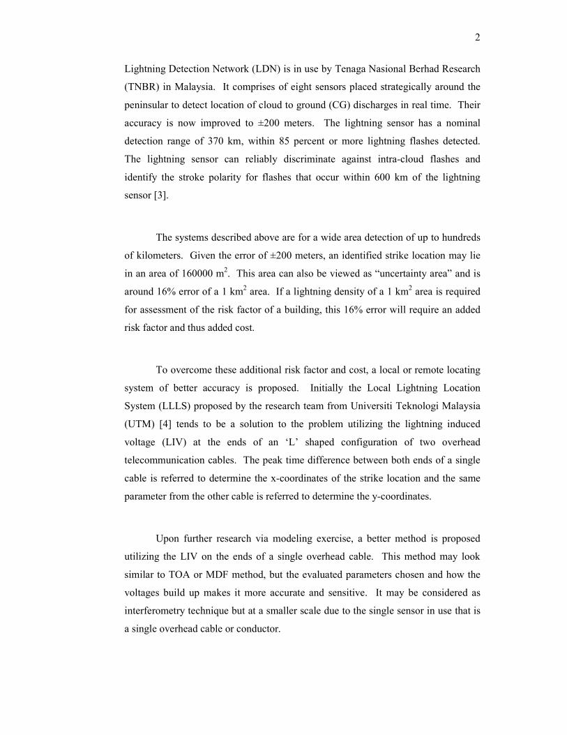
Lightning Detection Network (LDN) is in use by Tenaga Nasional Berhad Research
(TNBR) in Malaysia. It comprises of eight sensors placed strategically around the
peninsular to detect location of cloud to ground (CG) discharges in real time. Their
accuracy is now improved to ±200 meters. The lightning sensor has a nominal
detection range of 370 km, within 85 percent or more lightning flashes detected.
The lightning sensor can reliably discriminate against intra-cloud flashes and
identify the stroke polarity for flashes that occur within 600 km of the lightning
sensor [3].
The systems described above are for a wide area detection of up to hundreds
of kilometers. Given the error of ±200 meters, an identified strike location may lie
in an area of 160000 m2. This area can also be viewed as “uncertainty area” and is
around 16% error of a 1 km2 area. If a lightning density of a 1 km2 area is required
for assessment of the risk factor of a building, this 16% error will require an added
risk factor and thus added cost.
To overcome these additional risk factor and cost, a local or remote locating
system of better accuracy is proposed. Initially the Local Lightning Location
System (LLLS) proposed by the research team from Universiti Teknologi Malaysia
(UTM) [4] tends to be a solution to the problem utilizing the lightning induced
voltage (LIV) at the ends of an ‘L’ shaped configuration of two overhead
telecommunication cables. The peak time difference between both ends of a single
cable is referred to determine the x-coordinates of the strike location and the same
parameter from the other cable is referred to determine the y-coordinates.
Upon further research via modeling exercise, a better method is proposed
utilizing the LIV on the ends of a single overhead cable. This method may look
similar to TOA or MDF method, but the evaluated parameters chosen and how the
voltages build up makes it more accurate and sensitive. It may be considered as
interferometry technique but at a smaller scale due to the single sensor in use that is
a single overhead cable or conductor.
3
LIV on overhead conductors is of research interest due to their damaging
effects to electric systems since 1930’s. Though immune to LIV, high voltage
transmission systems are still exposed to threat from direct lightning. Even then
Gothberg and Brookes [5], had proposed a raw design of a wood and steel tower that
can withstand direct lightning stroke. The indirect effects of lightning are also in
interest of research until present.
Thottappillil [6] characterizes the total lightning electromagnetic pulse
environment from combined individual processes in lightning such as return strokes,
preliminary breakdown pulses, pulses associated with the leader process, K-changes
and M-changes, the isolated narrow bipolar pulses, and the pulse bursts. Srinivasan
[7] describes lightning as atmospheric electricity, its behavior and possibility to tap
energy. Although brief, the explanation on atmospheric electricity is exact, but the
possibility if tapping the energy from lightning is vaguely explained.
Distribution systems are vulnerable to nearby LIV and the present locating
system partially helps the preventive measures against their damaging effects due to
the location accuracy issue. Studies on the nearby LIV has been conducted for
example by Omidiora and Lehtonen [8] where experimental results of measured LIV
on overhead cables when lightning strikes a nearby tree, and in [9] whereby the
Supervisory, Control and Data Acquisition (SCADA) information is correlated to
the LLS data to automatically locate a fault on the line. They report the errors on
LA contribution on their study and suggest the need for LLS data of better resolution
to further improve the outcome of their study.

4
1.2 Problem Statement
The accuracy and sensitivity of large area lightning location systems are
acceptable for the large area in concern. For example, a study conducted for the
Guang Dong lightning location system (LLS) results in the median error of location
accuracy (LA) of approximately 1.32 km and overall detection efficiency (DE) of
approximately 86% [10]. Those data is for a coverage area of approximately
176,948 km2. Although small in percentage, that error may be significant if we are
considering the lightning risk for a building or a plant which may require LA of at
most 100 m for a 1 km2 area. If the data can be resolved further for study of the risk
factor, a better risk factor can be achieved. That information would result in a more
cost efficient lightning protection.
Many existing LLS are developed for covering large areas such as for a
country or large district. Data from existing LLS is available but LA for that much
smaller particular area is a concern. A solution for LA would be to have localized
LLS covering a smaller specific area for a period of time. Further existing LLS
uses a number of sensors either widely spaced, or vice versa when combined with
interferometry concept. When the accuracy of locating and detecting CG lightning
is of importance such as assessing the risk factor of a remote area, a better method
with improved accuracy and sensitivity would be of a much better choice.
The need to have a better resolution of the ground flash density (GFD) maps
is expressed by Kosmac [11], whereby the lightning threat in distribution networks
is evaluated. Large location accuracy of a LLS remains a problem for that research
and statistical method is employed to further improve the resolution of the LLS data
from the available coarse data.
It would be of better advantage if the LIV on distribution and transmission
cables is utilized to give information of approaching thunderstorm activity or exact
location of the CG lightning to assess the immunity of the distribution networks
against LIV. Furthermore, the LIV are available at terminated segments of the
5
networks and thus readily available. Introduction of localized LLS would be of
convenience in these types of studies.
A localized LLS would also be advantageous in an effort to evaluate the
existing wide area LLS such as in [12] by Aulia. An example whereby the recorded
and measured lightning striking the Canadian National Tower in Toronto is used to
evaluate the LA and DE of the North American Lightning Detection Network
(NALDN) which is presented in [13] by Lafkovici. Each strike to the tower would
be compared to the detected and located strike data of the NALDN. A localized
LLS described in the first paragraph would be suitable for this purpose as well and
the application is not restricted to towers only but further expanded across the
continent as the overhead cables spans throughout.
Paragraphs above describe the need for a local lightning locating system
(LLLS) that would be able to locate CG lightning of some acceptable resolution
within a particular area. The resulting data would be of better use in terms of
assessing the lightning risk factor of that particular area, contributive data for
research and even suitable for use in an effective early warning system. The
outcome of this research aims to cater the problems listed above, in proposing a
method that would be applicable for detecting lightning within a smaller area, with
acceptable LA and DE, and most importantly of a low cost set-up. The proposed
method would be applicable in systems of overhead conductor or conductors, with
minimal measurements at spaced terminations and time synchronized by a global
positioning system (GPS). The processing of the signals is in time domain thus
applicable for real time measurement.

6
1.3 Objective Recently, a study by the LLLS team had been done in order to achieve a
better design of lightning protection such as the effect of distance and height of a
Telecommunication Subscriber Lines (TSL) to lightning strike position [12]. From
thereon, the objectives of this research is as follows
(i) To propose a new method of locating CG lightning strike location from
the LIV at the ends of an overhead conductor terminated to ground by
referring to ∆tp and ∆vp between both ends of the overhead conductor.
∆tp is the difference of the peak time and estimates the x-coordinate of
the strike location, and ∆vp is the difference of the peak amplitude and
estimates the y-coordinate of the strike location in an x-y axis on the
ground from a plan view of the surrounding area.
(ii) To mathematically model the LIV at both ends of an overhead conductor
employing available established model and simulate the LIV for different
strike locations to show the relationship of ∆tp and ∆vp to the strike
location.
(iii) To further extend the mathematical modeling to existing overhead
conductor system i.e. telecommunication, distribution and transmission
systems.
(iv) To identify the weaknesses of the proposed method and find solutions to
overcome them.

7
1.4 Scope
Due to the vast area to be further assessed in the area of lightning and
response of an overhead conductor to its electromagnetic field, the research is
limited to
(i) The study of LIV due to the return stroke current of CG downward
negative lightning. A lightning flash consists of many processes
occurring in sequence and timeframes. The return stroke current is the
most intense of them and therefore chosen with expectance of better
sensitivity. Further the occurrence of the processes prior and after the
return stroke does not alter the quantities of the two parameters in
concern as they are spaced milliseconds apart and the LIV of each
process can be singularly identified.
(ii) The results are from a mathematical modeling exercise with a number of
assumptions as listed in Section 3.5.1 during the modeling stage.
Nonetheless, the assumptions adopted are acceptable within their
practical ranges in comparison to the techniques adopted in estimating
the peak LIV for purposes of insulation coordination.
(iii) The proposed method and their following modeling work are concerned
with only for conductors above ground. Underground cables are armored
and their sheaths are grounded thus a better model will be required.
(iv) The research does not analyze the error of the LA and the DE. It does
not consider the LIV from intra-cloud and inter-cloud discharges.
(v) The modeling results and the proposed method are analyzed for a flat
area without terrains, structures or vegetations that would alter the
propagation of the electromagnetic fields to the point of interest.
(vi) The overhead conductor is limited to a single overhead conductor
terminated to ground.

8
1.5 Contributions of the research
The contributions from the research are listed below. They are arranged
according to their importance and relevance.
(i) Proposal of a method to locate nearby lightning from simple analysis
of the voltages induced at both ends of a terminated overhead
conductor. The parameters ∆tp (peak time difference) and ∆vp (peak
amplitude difference) between the two synchronized measurements at
each terminated end is indicative of the lateral location of the CG
return stroke (with respect to the overhead conductor stretch) and the
distance away from the sides of the conductor respectively. The
method performs better in terms of LA and DE than a large area
network, for a given smaller area nearby the overhead conductor.
(ii) The development of a C++ based mathematical modeling program
which is robust to the parameters of the CG return stroke current,
overhead conductor, and of the surroundings such as the finite ground
conductivity. The modeling aims to calculate the LIV on overhead
conductors from dipoles of a vertically aligned upward CG return
stroke channel current.
(iii) The analysis of the modeling results that shows the relationship of the
CG strike location to ∆tp (peak time difference) and ∆vp (peak
amplitude difference) in supporting the proposed method.
(iv) Analysis of the shortfalls of the proposed method prevalent from the
results of the modeling exercise above. Amongst the shortfalls are
the ‘blind lines’ that exists exactly on the perpendicular axis bisecting
the overhead conductor at its center.
(v) Proposal of schemes of solution to overcome the shortfalls discussed
above which utilizes the set-up of different configurations of a pair of
overhead conductors.

9
1.6 Structure of the thesis
Chapter 2 details the related literature review of the research. They include
review on existing lightning locating systems, C++ codes, lightning electromagnetic
fields and their propagation through finite ground conductivity, coupling of fields to
line, and travelling waves on overhead conductor. The reviews are by no means
extensive but closely related to the research topics covered.
Chapter 3 spreads out the methodology and procedures adopted in obtaining
the experimental results, on-site measurement results and a detailed explanation on
the mathematical modeling exercise. Since the mathematical modeling is the result
of the author’s own effort from the basic engine from Sorwar [4], detailed but not
exhaustive C++ modeling flow is presented.
Chapter 4 presents the results of the experimental works, on-site
measurements, parametric evaluation of the mathematical modeling exercise and
existing overhead system modeling for telecommunication cable, ground wire of a
transmission system and a single phase distribution cable. Validation of the
mathematical modeling result is made by comparison with the on-site measurements
and other research modeling result which is established and compared with actual
site measurements. In this chapter, the approach of the proposed method is further
detailed based on the results generated.
Chapter 5 is devoted to discussing the outcome of the results in supporting
the proposed lightning locating method applied on existing overhead conductor
systems. Further evaluation reveals shortfalls of the proposed method. The
shortfalls are further discussed in an effort to explain the proposed solution schemes
to overcome those shortfalls. The proposed solutions have not been tested through
the mathematical modeling exercise but by geometrical comparison and utilizing the
TOA into the proposed method.

10
Chapter 6 concludes the contribution of the research and thesis with
suggestion of further works based on shortcomings of the assumptions adopted in
the mathematical modeling. A section is also devoted to possible usefulness of the
proposed method and its advantage compared to existing locating system.

REFERENCES
1. Lees, M.I.; , "Lightning activity in the UK," Lightning Protection of Wind
Turbines (Digest No: 1997/303), IEE Half-Day Colloquium on , vol., no.,
pp.2/1-2/3, 26 Nov 1997.
2. Hidayat, S.; Sirait, K.T.; Pakpahan, P.M.; Ishii, M.; Hojo, J.; , "Lightning
characteristics on Java Island, observed by lightning location network," High
Voltage Engineering, 1999. Eleventh International Symposium on (Conf.
Publ. No. 467) , vol.2, no., pp.192-195 vol.2, 1999.
3. Abdullah, N.; Yahaya, M.P.; Hudi, N.S.; , "Implementation and use of
lightning detection network in Malaysia," Power and Energy Conference,
2008. PECon 2008. IEEE 2nd International , vol., no., pp.383-386, 1-3 Dec.
2008.
4. Aulia. A new lightning location system using telecommunication overhead
lines. Thesis, (M. Eng). Universiti Teknologi Malaysia; 2009
5. Gothberg, A. W.; Brookes, A. S.; , "Lightning Protection for Transmission
Lines," American Institute of Electrical Engineers, Transactions of the ,
vol.56, no.1, pp.13-16, Jan. 1937.
6. Thottappillil, R.; , "Electromagnetic pulse environment of cloud-to-ground
lightning for EMC studies," Electromagnetic Compatibility, IEEE
Transactions on , vol.44, no.1, pp.203-213, Feb 2002.
7. Srinivasan, K.; Gu J.; , "Lightning as Atmospheric Electricity," Electrical
and Computer Engineering, 2006. CCECE '06. Canadian Conference on ,
vol., no., pp.2258-2261, May 2006.

161
8. Omidiora, M.A.; Lehtonen, M.; , "Experimental performance of induced
voltage on power line due to lightning discharge to nearby tree," Modern
Electric Power Systems (MEPS), 2010 Proceedings of the International
Symposium , vol., no., pp.1-5, 20-22 Sept. 2010.
9. Kosmac, J.; Djurica, V.; Babuder, M.; , "Automatic fault localization based
on lightning information," IEEE Power Engineering Society General
Meeting, 2006.
10. Chen, S.M.; Du, Y.; Fan, L.M.; He, H.M.; Zhong, D.Z.; , "Evaluation of the
Guang Dong lightning location system with transmission line fault data,"
Science, Measurement and Technology, IEE Proceedings - , vol.149, no.1,
pp.9-16, Jan 2002.
11. Kosmac, J.; Gasper, L.J.; Vladimir, D.; Zvonko, T.;, "Evaluation of lightning
threat in distribution networks," Electricity Distribution - Part 1, 2009.
CIRED 2009. 20th International Conference and Exhibition on , vol., no.,
pp.1-4, 8-11 June 2009.
12. Aulia; Abdul Malek, Z.; Adzis Z.; ,“The Surge Induced Voltage on a Small
scale Model of Telecommunication Subscriber Lines (TSL) in Different
Height and Distance: Experimental Approach”, Commet, UTM, 2008.
13. Lafkovici, A.; Hussein, A.M.; Janischewskyj, W.; Cummins, K.L.; ,
"Evaluation of the Performance Characteristics of the North American
Lightning Detection Network Based on Tall-Structure Lightning,"
Electromagnetic Compatibility, IEEE Transactions on , vol.50, no.3, pp.630-
641, Aug. 2008.
14. Md. Golam Sorwar Hossain. Analysis of induced surges on overhead
telecommunication subscriber line due to lightning return stroke. Thesis, (M.
Eng). Universiti Teknologi Malaysia. 1998.
15. Rakov, V. A., Uman, M.A. Lightning physics and effects. UK: Cambridge
University Press. (2003)

162
16. Stolzenburg, M., W. D. Rust, and T. C. Marshall, Electrical structure in
thunderstorm convective regions. 3. Synthesis, J. Geophys. Res.,
D103,14097-14108, 1998.
17. Cooray, V. The Lightning Flash, UK:IEE London, (2003)
18. M.A. Uman, D.K. McLain, and E.P. Krider. The Electromagnetic Radiation
from a Finite Antenna, Am. J. Phys., 43, 33-38 (1975).
19. Uman, M.A.; , "Natural lightning," Industrial and Commercial Power
Systems Technical Conference, 1993. Conference Record, Papers Presented
at the 1993 Annual Meeting , vol., no., pp.1-7, 2-6 May 1993.
20. Mo, F.; Jiang, J.; Huang, Y.; Wang, T.; , "Study the induced voltage caused
by lightning flash to overhead power lines tower," Power Electronics and
Motion Control Conference, 2009. IPEMC '09. IEEE 6th International , vol.,
no., pp.2521-2526, 17-20 May 2009.
21. Napolitano, F.; Paolone, M.; Borghetti, A.; Nucci, C.A.; Rachidi, F.; Rakov,
V.A.; Schoene, J.; Uman, M.A.; , "Interaction between grounding systems
and nearby lightning for the calculation of overvoltages in overhead
distribution lines," PowerTech, 2011 IEEE Trondheim , vol., no., pp.1-7, 19-
23 June 2011.
22. Kumar, U.; Hegde, V.; Shivanand, V.; , "Preliminary Studies on the
Characteristics of the Induced Currents in Simple Down Conductors Due to a
Nearby Lightning Strike," Electromagnetic Compatibility, IEEE
Transactions on , vol.48, no.4, pp.805-816, Nov. 2006.
23. Mousa, A.M.; Srivastava, K.D.; , "The implications of the electrogeometric
model regarding effect of height of structure on the median amplitude of
collected lightning strokes," Power Delivery, IEEE Transactions on , vol.4,
no.2, pp.1450-1460, Apr 1989.
24. Haigh, S.J.; Hardwick, C.J.; , "The determination of induced voltage due to
lightning with the aid of computer modelling," Lightning and EMC, IEE
Colloquium on , vol., no., pp.4/1-4/7, 30 Jan 1996.

163
25. Nucci, C.A. Rachidi, F. “On the contribution of the electromagnetic field
components in field-to-transmission line interaction “, Electromagnetic
Compatibility, IEEE Transactions on, Nov 1995, Volume: 37 Issue: 4,
page(s): 505 – 508.
26. Nucci, C.A.; , "The Lightning Induced Over-Voltage (LIOV) code," Power
Engineering Society Winter Meeting, 2000. IEEE , vol.4, no., pp.2417-2418
vol.4, 2000.
27. Paolone, M. Modeling of lightning induced voltages on distribution networks
for the solution of power quality problems, and relevant implementation in a
transient program. Thesis, (PhD). University of Bologna. (2001)
28. Dommel, H., Electromagnetic Transient Program Theory Book, Oregon:
Bonneville Power Administration. (1974)
29. A. K. Agrawal, H. J. Price, and S. H. Gurbaxani, “Transient response of
multiconductor transmission lines excited by a nonuniform electromagnetic
field,” IEEE Trans. Electromagn. Compat., vol. EMC-22, pp. 119–129, May
1980.
30. Ren, H.M.; Zhou, B.H.; Rakov, V.A.; Shi, L.H.; Gao, C.; Yang, J.H.; ,
"Analysis of Lightning-Induced Voltages on Overhead Lines Using a 2-D
FDTD Method and Agrawal Coupling Model," Electromagnetic
Compatibility, IEEE Transactions on , vol.50, no.3, pp.651-659, Aug. 2008.
31. Paolone, M.; Rachidi, F.; Borghetti, A.; Nucci, C.A.; Rubinstein, M.; Rakov,
V.A.; Uman, M.A.; , "Lightning Electromagnetic Field Coupling to
Overhead Lines: Theory, Numerical Simulations, and Experimental
Validation," Electromagnetic Compatibility, IEEE Transactions on , vol.51,
no.3, pp.532-547, Aug. 2009.
32. Peretto, L.; Rinaldi, P.; Sasdelli, R.; Tinarelli, R.; Fioravanti, A.; ,
"Implementation and Characterization of a System for the Evaluation of the
Starting Instant of Lightning-Induced Transients," Instrumentation and
Measurement, IEEE Transactions on , vol.56, no.5, pp.1955-1960, Oct.
2007.

164
33. Peretto, L.; Rinaldi, P.; Sasdelli, R.; Tinarelli, R.; , "A system for the
measurement of the starting instant of impulsive transients [power systems],"
Instrumentation and Measurement Technology Conference, 2004. IMTC 04.
Proceedings of the 21st IEEE , vol.2, no., pp. 1394- 1398 Vol.2, 18-20 May
2004.
34. Xie, Y.; Xue, Y.; Chen, J.; Wang, H.; Xue, F.; , "Extensions of power system
early-warning defense schemes by integrating wide area meteorological
information," Electric Utility Deregulation and Restructuring and Power
Technologies (DRPT), 2011 4th International Conference on , vol., no.,
pp.57-62, 6-9 July 2011.
35. Cummins, K.L.; Murphy, M.J.; , "An Overview of Lightning Locating
Systems: History, Techniques, and Data Uses, With an In-Depth Look at the
U.S. NLDN," Electromagnetic Compatibility, IEEE Transactions on , vol.51,
no.3, pp.499-518, Aug. 2009.
36. Cummins, K.L.; Krider, E.P.; Malone, M.D.; , "The US National Lightning
Detection NetworkTM and applications of cloud-to-ground lightning data by
electric power utilities," Electromagnetic Compatibility, IEEE Transactions
on , vol.40, no.4, pp.465-480, Nov 1998
37. Wu, Y.; Fan, C.; Li, Y.; Wang, B.; , "Design of Lightning Location System
Based on Photon and Infrasound Detection," Electronic Measurement and
Instruments, 2007. ICEMI '07. 8th International Conference on , vol., no.,
pp.1-603-1-606, Aug. 16 2007-July 18 2007.
38. Abidin, H.Z.; Ibrahim, R.; , "Thunderstorm day and ground flash density in
Malaysia," Power Engineering Conference, 2003. PECon 2003.
Proceedings. National , vol., no., pp. 217- 219, 15-16 Dec. 2003.
39. H. Ahmad, Kilat dan Perlindungan, Penerbitan UTM, 1998
40. M. P. Yahya, H. Ahmad and M. A. Alam, "Lightning Detection System in
Malaysia." National Technical Seminar on Standardisation and
Development of Lightning Protection Technologies -Malaysian Environment,
PetalingJaya, Malaysia, 1996.
165
41. Hu, M.; Huang, X.; , "Lightning activity analysis and risk evaluation of
transmission line," Quality, Reliability, Risk, Maintenance, and Safety
Engineering (ICQR2MSE), 2011 International Conference on , vol., no.,
pp.158-161, 17-19 June 2011.
42. Diendorfer, G.; Schulz, W.; , "Ground flash density and lightning exposure
of power transmission lines," Power Tech Conference Proceedings, 2003
IEEE Bologna , vol.3, no., pp. 3 pp. Vol.3, 23-26 June 2003.
43. Chen, S.M.; Du, Y.; Fan, L.M.; He, H.M.; Zhong, D.Z.; , "A lightning
location system in China: its performances and applications,"
Electromagnetic Compatibility, IEEE Transactions on , vol.44, no.4, pp.
555- 560, Nov 2002.
44. Wang, D.; Yuan, T.; Zhang, G.; Zhang, T.; , "Fast electric field change
pulses location technique," Electromagnetic Compatibility (APEMC), 2010
Asia-Pacific Symposium on , vol., no., pp.1158-1161, 12-16 April 2010.
45. Sattari, P.; Sheshyekani, K.; Hazrati, M.; Moini, R.; Sadeghi, S.H.H.; , "A
TDOA-based approach for locating cloud-to-ground lightning strokes, using
Taylor series expansion," Electromagnetic Compatibility, 2006. EMC-Zurich
2006. 17th International Zurich Symposium on , vol., no., pp.136-139, Feb.
27 2006-March 3 2006.
46. Hu, Z.X.; Wen, Y.P.; Zhao, W.G.; Zhu, H.P.; Liu, S.L.; , "Numerical
Simulation of Lightning Location Based on Monte Carlo Method,"
Management and Service Science, 2009. MASS '09. International Conference
on , vol., no., pp.1-4, 20-22 Sept. 2009.
47. Hu, Z.X.; Wen, Y.P.; Zhao, W.G.; Zhu, H.P.; , "Accuracy Analysis of the
TDOA Method in a Lightning Location System," Management and Service
Science, 2009. MASS '09. International Conference on , vol., no., pp.1-4, 20-
22 Sept. 2009.
48. Orville, R.; Songster, H.; , "The East Coast Lightning Detection Network,"
Power Delivery, IEEE Transactions on , vol.2, no.3, pp.899-907, July 1987.

166
49. Tatsumi, M.; Idogawa, T.; Nakamura, S.; Higashi, S.; Sezaki, A.; Uenishi,
K.; , "Lightning observation results by new LLS that uses LS8000 and
CP8000," Electromagnetic Compatibility (APEMC), 2010 Asia-Pacific
Symposium on , vol., no., pp.1150-1153, 12-16 April 2010.
50. Du, H.; Ma, H.; Zhang, Y.; , "A novel algorithm for real-time adaptive signal
detection in lightning location system," Information Science and Engineering
(ICISE), 2010 2nd International Conference on , vol., no., pp.1-4, 4-6 Dec.
2010.
51. Huang, Z.; Wang, X.; Chen, S.; Zhang, Y.; Dong, W.; Yin, Q.; , "Analysis
on the induced overvoltage generated by near triggered lightning in the AWS
power distribution system," Electromagnetic Compatibility (APEMC), 2010
Asia-Pacific Symposium on , vol., no., pp.1522-1525, 12-16 April 2010.
52. Silvino, J.L.; Mesquita, C.R.; Visacro, S.F.; , "Non-direct lightning current
measurement for lightning location systems calibration," Electronics Letters
, vol.39, no.6, pp. 504- 505, 20 March 2003.
53. Matsui, M.; Takano, N.; , "Evaluation of Lightning Location accuracy of
JLDN with a lightning video camera system," Electromagnetic Compatibility
(APEMC), 2010 Asia-Pacific Symposium on , vol., no., pp.1142-1145, 12-16
April 2010.
54. Abdul-Malek, Z.; Adzis, Z.; Aulia; Novizon; Abdullah, N.; , "Waveform and
location analyses of localised lightning locating system," High Voltage
Engineering and Application (ICHVE), 2010 International Conference on ,
vol., no., pp.132-135, 11-14 Oct. 2010.
55. Manoochehrnia, P.; Rachidi, F.; Rubinstein, M.; Schulz, W.; Diendorfer, G.;
, "Benford's Law and Its Application to Lightning Data," Electromagnetic
Compatibility, IEEE Transactions on , vol.52, no.4, pp.956-961, Nov. 2010.
56. Chowdhuri P., Li S., Yan P., ‘Review of research on lightning-induced
voltages on an overhead line’, Generation, Transmission and Distribution,
IEE Proceedings, Jan 2001, Volume: 148, Issue: 1 page(s) 91-95.
167
57. Kannu, P.D.; Thomas, M.J.; “Computation of lightning induced voltages on
telecommunication subscriber lines”, Electromagnetic Interference and
Compatibility. Proceedings of the International Conference on, 21-23 Feb.
2002 Page(s):79 - 83.
58. K Chrysanthou, C. Parente, M., ‘Data errors caused by surge voltages on
paired-conductor lines’, Power Delivery, IEEE Transactions, Jan 2001, Vol
16, Issue: 1, pp 131-137.
59. Kannu, P.D.; Thomas, M.J.; “Lightning induced voltages on multiconductor
power distribution line”, Generation, Transmission and Distribution, IEE
Proceedings-, Volume 152, Issue 6, 4 Nov. 2005 Page(s):855 - 863.
60. Galvan, A.; Cooray, V.; Scuka, V.;, “Interaction of electromagnetic fields
from cloud and ground lightning flashes with an artificial low-voltage power
installation”, Electromagnetic Compatibility, IEEE Transactions on’ Volume
41, Issue 3, Aug. 1999 Page(s):250 – 257.
61. Rakov, V.A.; Rachidi, F.; , "Overview of Recent Progress in Lightning
Research and Lightning Protection," Electromagnetic Compatibility, IEEE
Transactions on , vol.51, no.3, pp.428-442, Aug. 2009.
62. Hoidalen, H.K.; Sletbak, J.; Henriksen, T.; , "Ground effects on induced
voltages from nearby lightning," Electromagnetic Compatibility, IEEE
Transactions on , vol.39, no.4, pp.269-278, Nov 1997.
63. Paulino, J.O.S.; Barbosa, C.F.; Lopes, I.J.S.; do Couto Boaventura, W.; , "An
Approximate Formula for the Peak Value of Lightning-Induced Voltages in
Overhead Lines," Power Delivery, IEEE Transactions on , vol.25, no.2,
pp.843-851, April 2010.
64. Barbosa, C.F.; Paulino, J.O.S.; , "An Approximate Time-Domain Formula
for the Calculation of the Horizontal Electric Field from Lightning,"
Electromagnetic Compatibility, IEEE Transactions on , vol.49, no.3, pp.593-
601, Aug. 2007.

168
65. Baba, Y.; Rakov, V.A.; , "Voltages induced on an overhead wire by
lightning strikes to a nearby tall grounded object," Electromagnetic
Compatibility, IEEE Transactions on , vol.48, no.1, pp.212-224, Feb. 2006.
66. Rubinstein, M.; Uman,M. A.; “Methods for calculating the electromagnetic
fields from a know source distribution: Aplication to lightning,” IEEE
transaction on Electromagnetic Compatibility, vol. 31, May 1989.
67. Rubinstein, M.;, “An approximate formula for the calculation of the
horizontal electric field from lightning at close, intermediate, and long
range,” IEEE Trans. Electromagn. Compat., vol. 38, pp. 531–535, Aug.1996.
68. Uman, M. A.;, “Lightning return stroke electric and magnetic fields,” J.
Geophys. Res., vol. 90, pp. 6121–6130, 1985.
69. Rubinstein, M; Uman, M. A.;. “Methods for calculating the electromagnetic
fields from a know source distribution: Aplication to lightning,” IEEE
transaction on Electromagnetic Compatibility, vol. 31, May 1989.
70. Master, M.J.; Uman, M.A.; Beasley, W.H.; Darveniza, M.;, “Lightning
induced voltages on power lines:Experiment,” IEEE Trans. Power. App.
Syst., vol. 103,pp. 2519-2529, 1984.
71. Thottappillil, R.; Rakov, V.A.; “On the computation of electric fields from a
lightning discharge in time domain,” EMC. 2001 IEEE International
Symposium on, Volume 2, 13-17 Aug. 2001 Page(s):1030 - 1035 vol.2.
72. Nucci, C.A.; Rachidi, F.; Ianoz, M.; Mazzetti, C.; , "Comparison of two
coupling models for lightning-induced overvoltage calculations," Power
Delivery, IEEE Transactions on , vol.10, no.1, pp.330-339, Jan 1995.
73. Silveira, F.H.; Visacro, S.; , "On the Lightning-Induced Voltage Amplitude:
First Versus Subsequent Negative Strokes," Electromagnetic Compatibility,
IEEE Transactions on , vol.51, no.3, pp.741-747, Aug. 2009.
74. Sarkar, M.Z.I.; Ali, A.M.; , "Analysis of lightning induced electric field and
its components on and above the lossy earth's surface by modified dipole
technique," TENCON '02. Proceedings. 2002 IEEE Region 10 Conference on

169
Computers, Communications, Control and Power Engineering , vol.3, no.,
pp. 1893- 1896 vol.3, 28-31 Oct. 2002.
75. Siti Rabiatul Adawiyah, Lightning Location from induced voltages: An
experimental approach. Thesis (BEng) Universiti Teknologi Malaysia,
(2011)
76. Carson, J.R.;, “Wave propagation in overhead wires with ground return”
Bell Systems Tech. Journal, Vol. 5. Pp539-554, 1926.
77. Aulia; Malek, Z. A.; Adzis, Z.; Novizon;, A New Localised Lightning
Locating System Utilising Telecommunication Subscriber Line, 2ndIEEE
International Conference on Power and Energy (PECon 08), December 1-
3,2008, Johor Baharu, Malaysia
78. Taylor, C.; Satterwhite, R.; Harrison, C., Jr.; , "The response of a terminated
two-wire transmission line excited by a nonuniform electromagnetic field,"
Antennas and Propagation, IEEE Transactions on , vol.13, no.6, pp. 987-
989, Nov 1965.
79. Fink, D.G., Beaty, H.W., Standard Handbook for Electrical Engineers.
McGraw Hill Int. Edition. (2000:14th Ed)
80. Le Vine, D. M., L. Gesell, and M. Kao (1986), Radiation From Lightning
Return Strokes Over a Finitely Conducting Earth, J. Geophys. Res., 91(D11),
11,897–11,908.
81. Rakov, V.A.; Uman, M.A.; , "Review and evaluation of lightning return
stroke models including some aspects of their application," Electromagnetic
Compatibility, IEEE Transactions on , vol.40, no.4, pp.403-426, Nov 1998.
82. Hoidalen, H.K.; Sletbak, J.; Henriksen, T.; , "Ground effects on induced
voltages from nearby lightning," Electromagnetic Compatibility, IEEE
Transactions on , vol.39, no.4, pp.269-278, Nov 1997.
83. Rubinstein, M.; Romero, C.; Rachidi, F.; Rubinstein, A.; Vega, F.; , "A two-
station lightning location method based on a combination of difference of
time of arrival and amplitude attenuation," Electromagnetic Compatibility
170
(APEMC), 2010 Asia-Pacific Symposium on , vol., no., pp.1154-1157, 12-16
April 2010.
84. Hoidalen, H.K.; , "Analytical formulation of lightning-induced voltages on
multiconductor overhead lines above lossy ground," Electromagnetic
Compatibility, IEEE Transactions on , vol.45, no.1, pp. 92- 100, Feb 2003.
85. Ibrahim, W.I.; Ghazali, M.R.; Ghani, S.A.; Malek, Z.A.; , "Measurement of
vertical Electric fields from lightning flashes using parallel plate antenna,"
Electrical, Control and Computer Engineering (INECCE), 2011
International Conference on , vol., no., pp.466-471, 21-22 June 2011.
86. Rubinstein, M.; Romero, C.; Rachidi, F.; Rubinstein, A.; Vega, F.; , "A two-
station lightning location method based on a combination of difference of
time of arrival and amplitude attenuation," Electromagnetic Compatibility
(APEMC), 2010 Asia-Pacific Symposium on , vol., no., pp.1154-1157, 12-16
April 2010.